7. Level 2 Repair
7-1
Confidential and proprietary-the contents in this service guide subject to change without prior notice.
Distribution, transmission, or infringement of any content or data from this document without Samsung’s written authorization is strictly prohibited.
※ Caution
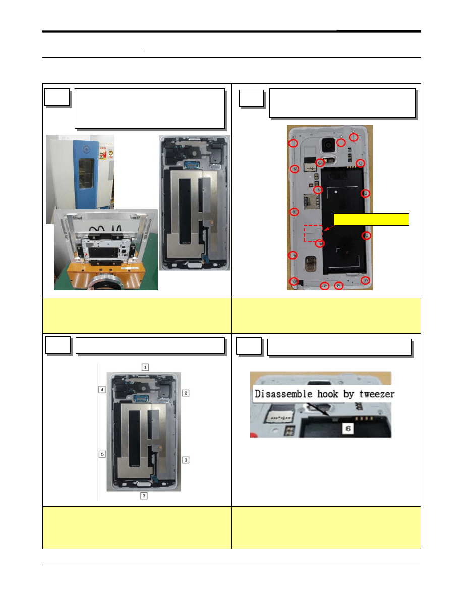
1) Displace the temperature chamber of 80℃
for 10 minute
2) Detach the OCTA using Vaccum jig
※ Caution
1) Be careful of scratch.
※ Caution
1) Disassemble rear case pushing BRAKCET
to outside
2) Be careful of bonding of SUS PLATE
※ Caution
1) Be careful of scratch.
1
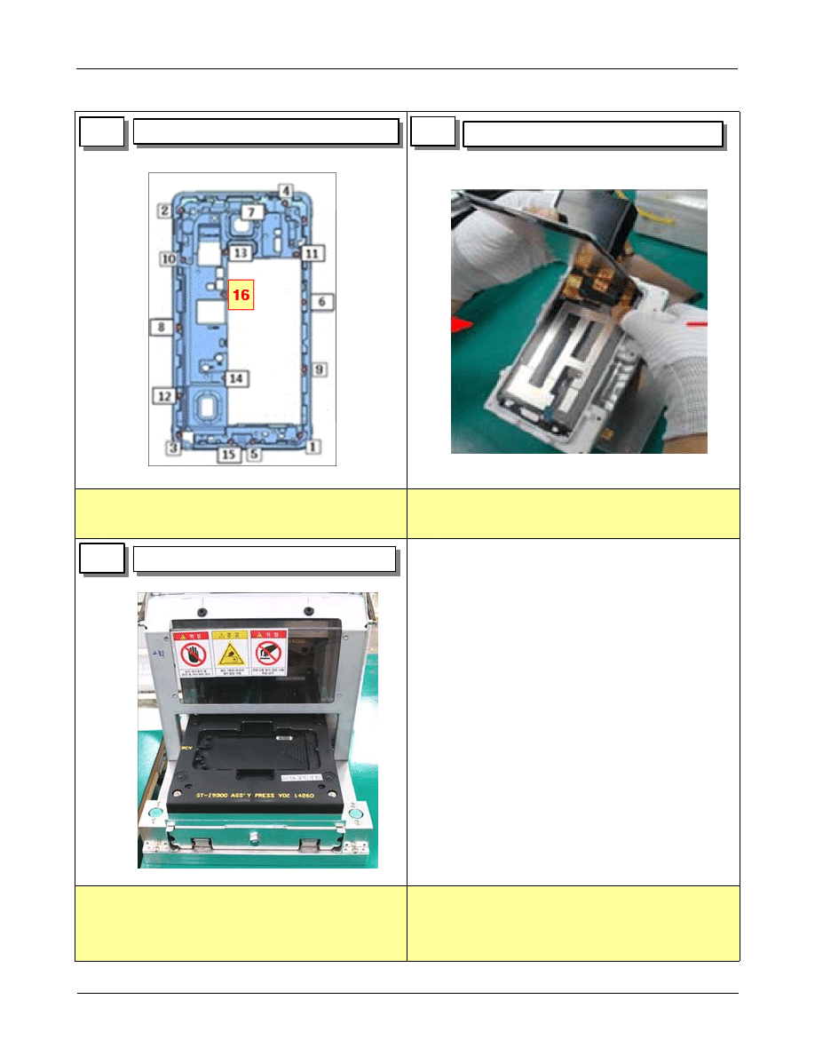
1) Displace the temperature chamber
of 80℃ for 10 minute
2) Detach the OCTA using Vaccum jig
2
1) Unscrew 16 points and disassemble
RF cap
3
1) Disassemble from side hook.
4
1) Disassemble inner hook of REAR.
Disassemble RF cap
7-1. Disassembly
Level 2 Repair
Distribution, transmission, or infringement of any content or data from this document without Samsung’s written authorization is strictly prohibited.
Confidential and proprietary-the contents in this service guide subject to change without prior notice.
7-2
※ Caution
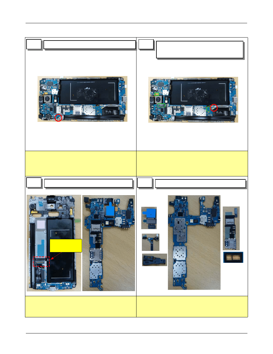
1) Be careful of scratch
※ Caution
1) Be careful of damage to the connectors and
coaxial cables.
※ Caution
1) Be careful of scratch
※ Caution
1) Be careful of scratch
2) Be careful of connector damage and FPCB
damage
5
6
1) Disassemble 3 connectors and 2
coaxial cables.
7
1) Seperate MAIN PBA, BRACKET.
8
1) Disassemble rest electronic material.
1) Unscrew 1 point
Disassemble
connector first
Level 2 Repair
Distribution, transmission, or infringement of any content or data from this document without Samsung’s written authorization is strictly prohibited.
Confidential and proprietary-the contents in this service guide subject to change without prior notice.
7-3
※ Caution
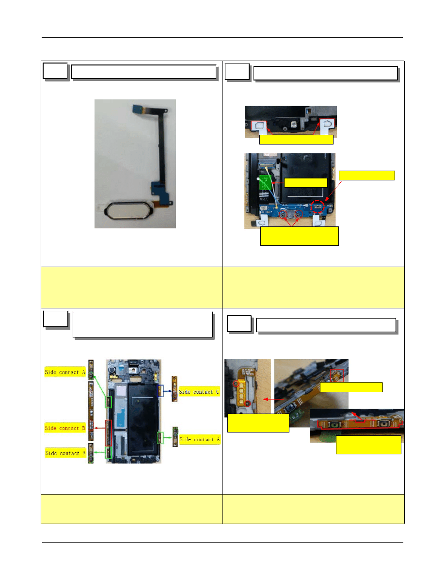
1) Be careful of connector damage and FPCB
damage
※ Caution
1) Be careful of connector damage and FPCB
damage
※ Caution
1) Be careful of connector and FPCB damage
※ Caution
1) Be careful of connector and FPCB damage
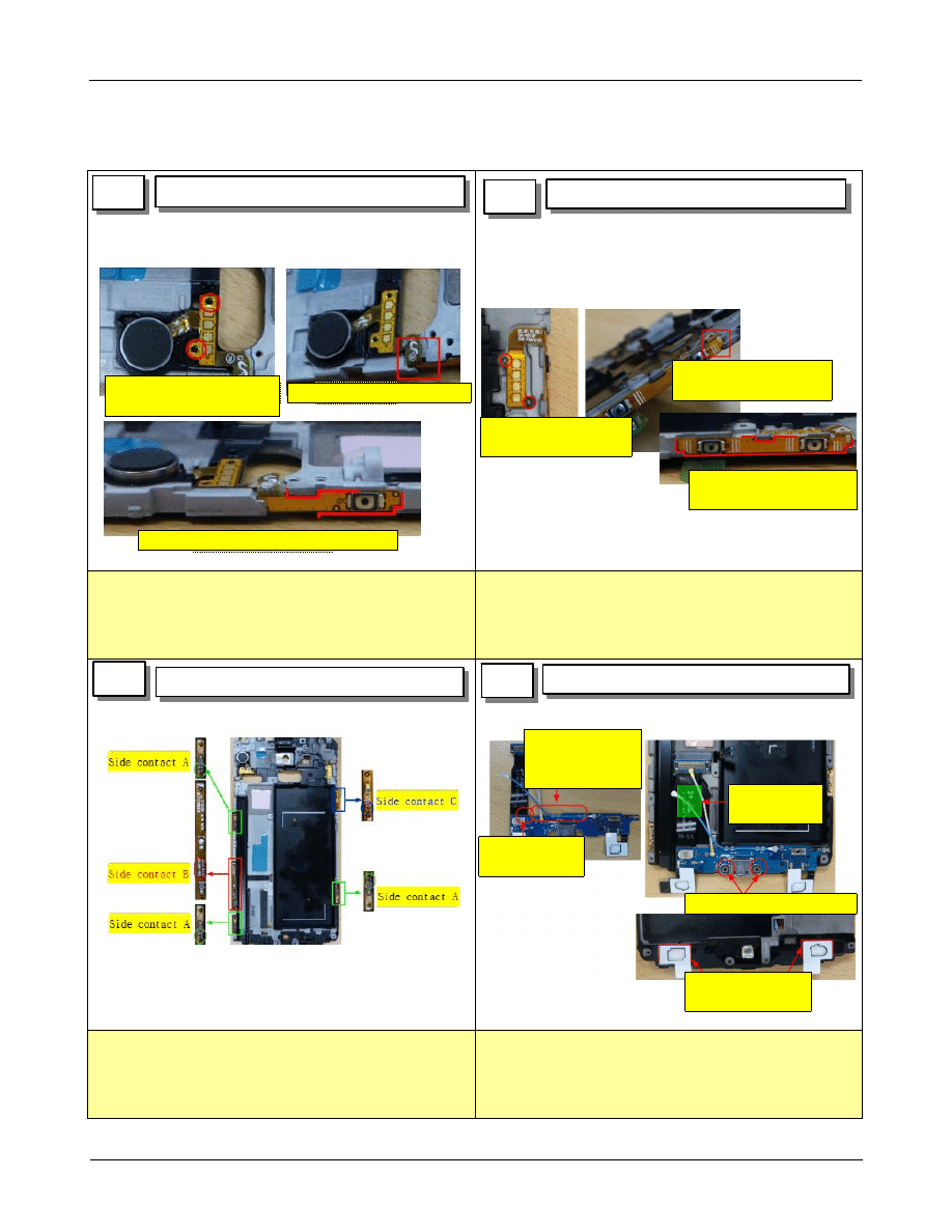
9
10
1) SUB PBA Disassemble
11
1) Disassemble SIDE contact FPCB 5
point
12
1) Volume key FPCB disassemble
1) HOME KEY Disassemble
1.disassemble volume
key first
2.disassemble hook
3.disassemble FPCB
from bracket
4.Disassemble (Be careful
not to damage it)
3.Detach FPCB
2.Disassemble touch key
1.unscrew 1 point
Level 2 Repair
Distribution, transmission, or infringement of any content or data from this document without Samsung’s written authorization is strictly prohibited.
Confidential and proprietary-the contents in this service guide subject to change without prior notice.
7-4
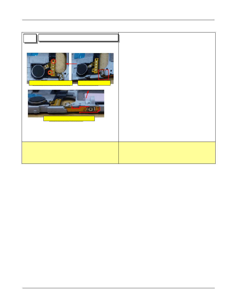
※ Caution
1) Be careful of connector and FPCB damage
13
1) disassemble motor
1.disassemble motor FPCB first
2.disassemble hook
3.disassemble from bracket
Level 2 Repair
Distribution, transmission, or infringement of any content or data from this document without Samsung’s written authorization is strictly prohibited.
Confidential and proprietary-the contents in this service guide subject to change without prior notice.
7-5
7-2. Assembly
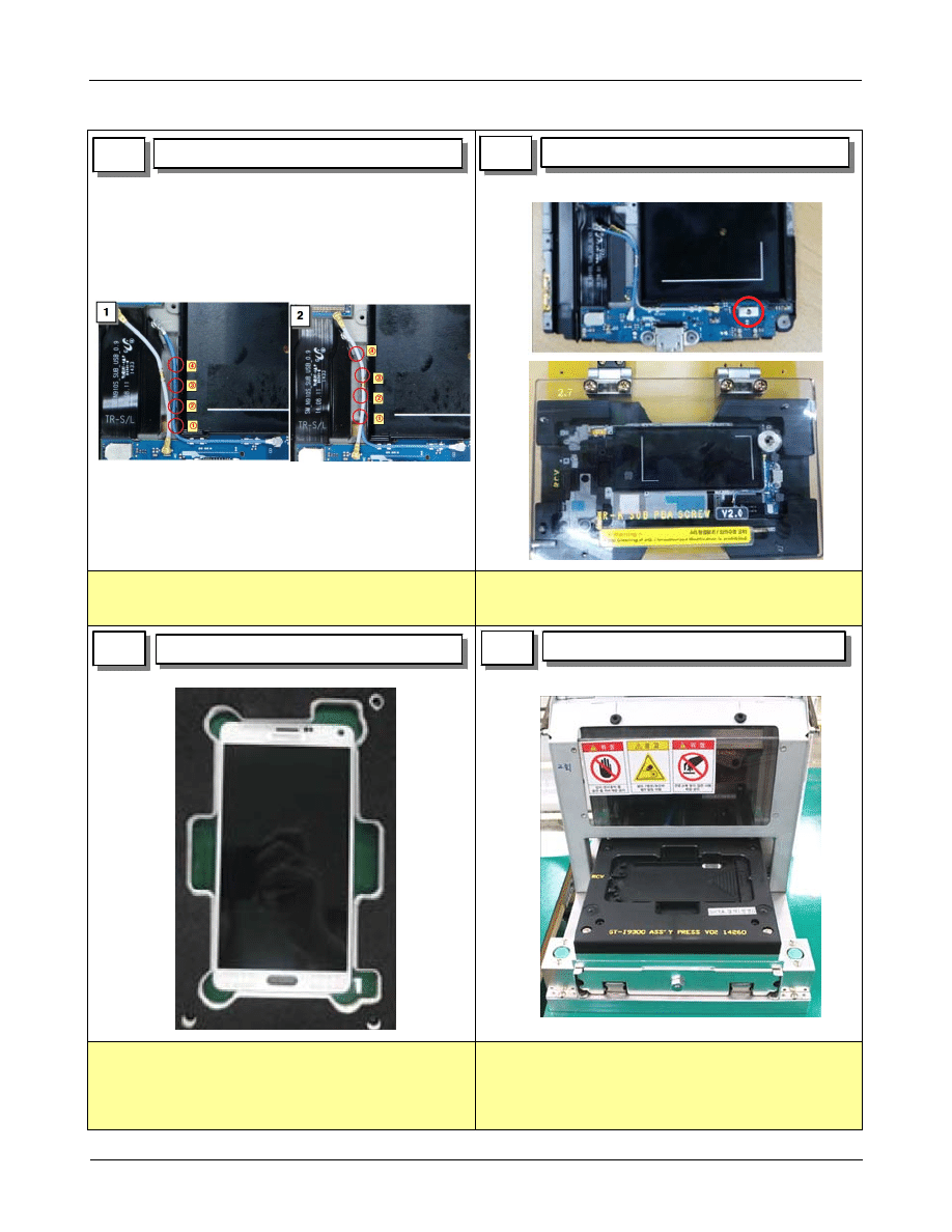
※ Caution
1) Be careful of FPCB tilt
※ Caution
1) Be careful of FPCB tilt
※ Caution
1) Be careful of reverse assembly
※ Caution
1) Be careful of TOUCH KEY LED damage
2) Be careful of TOUCH KEY LED damage
1
1) MOT FPCB assemble
2
1) volume key FPCB assemble
3
1) SIDE contact FPCB assembly
4
1) IF PBA assembly
1.attach motor following
guide hook.
2.insert FPCB through hole
3. attach FPCB following guide line
1.attach volume key
following guide hook.
2.attach FPCB following
guide home
3.attach FPCB following
guide line
attach KEY FPCB
following guide rib
attach following guide rib
press FPCB
to attach
Assemble white
RF cable
Assemble blue RF
cable and assemble
into the clip
Level 2 Repair
Distribution, transmission, or infringement of any content or data from this document without Samsung’s written authorization is strictly prohibited.
Confidential and proprietary-the contents in this service guide subject to change without prior notice.
7-6
※ Caution
1) Be careful not to be lifted up of FPCB
※ Caution
1) Check if screw is fully assembled.
※ Caution
1) Be careful of FPCB tilt
※ Caution
- press power : 5 ~ 6 kgf/cm
2
- press time : 4.7 sec
- be careful of damage
5
6
1) Screw 1 points
7
1) OCTA TAPE attach
1) OCTA press
1) Assemble RF cable
8
Level 2 Repair
Distribution, transmission, or infringement of any content or data from this document without Samsung’s written authorization is strictly prohibited.
Confidential and proprietary-the contents in this service guide subject to change without prior notice.
7-7
※ Caution
1) Be careful of FPCB tilt
※ Caution
1) Be careful of FPCB tilt
※ Caution
1) Be careful of connector pin damage
※ Caution
1) Be careful of FPCB tilt
9
10
1) DIGITIZER attach
1) OCTA CONN PORON attach
11
12
1) SENSOR BRACKET assemble
2) SENSOR assemble
1) Assemble camera
2) SIM/SD socket FPCB assemble
assemble hook
PUT following rib
and guide hole
assemble hook
PUT following rib and guide hole
assemble module
assemble connector
Be careful of
damage of pin
assemble connector
assemble connector
Attach FPCB following
guide hook
OK
NG
Check OCTA poron's TILT
Level 2 Repair
Distribution, transmission, or infringement of any content or data from this document without Samsung’s written authorization is strictly prohibited.
Confidential and proprietary-the contents in this service guide subject to change without prior notice.
7-8
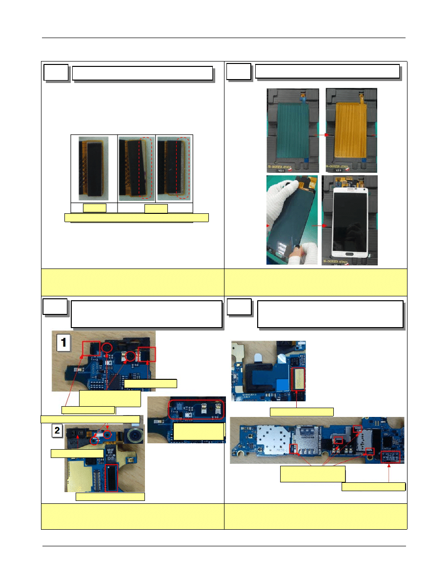
※ Caution
1) Be careful of connector damage and FPCB
damage.
2) Be careful of scratch
※ Caution
1) Be careful of connector damage and FPCB
damage.
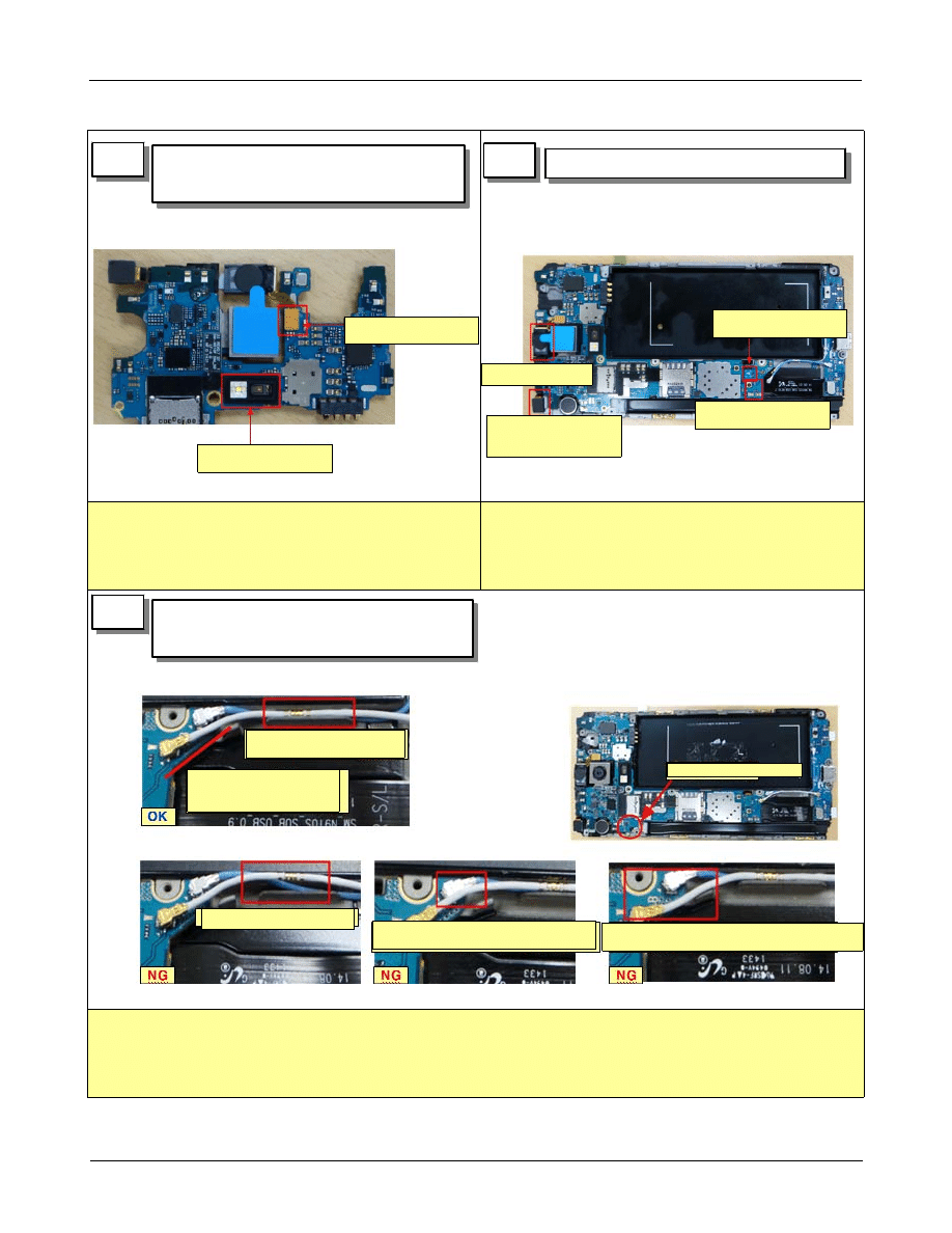
※ Caution
1) Be careful of
- cable coming up
- cable is lifted
13
14
1) PBA assemble
15
1) Assemble RF cable
2) PBA SCREW 1 point
1) HRM sensor rubber assembly
2) Assemble receiver connector
assemble receiver
connector
assemble HRM sensor
rubber
assemble home key
connector
assemble sub pba
connector
insert sub-cam
through bracket
hole
assemble receiver
and attach it
screw 1 point
there should be no
lift up of cable
white cable should be
inner side of PCB
cable coming up
white cable is overlapped on
blue cable
cable is outter side of PCB. it will
be overlapped on spk module too.
Level 2 Repair
Distribution, transmission, or infringement of any content or data from this document without Samsung’s written authorization is strictly prohibited.
Confidential and proprietary-the contents in this service guide subject to change without prior notice.
7-9
※ Caution
1) Be careful of scratch
※ Caution
1) Check if connector is fully assembled or not
※ Caution
- press power : 5 ~ 6 kgf/cm
2
- press time : 11.7 sec
- be careful not to damage
16
17
1) OCTA assemble
18
1) OCTA press
1) REAR SCREW 16 points
Wyszukiwarka
Podobne podstrony:
ARTICLE SUSPENSION STRUT FRONT DISASSEMBLE REASSEMBLE
Disassembly & Reassembly
ARTICLE SUSPENSION STRUT REAR DISASSEMBLE REASSEMBLE
Disassembly & Reassembly
7 Disassembly & Reassembly
Disassembly & Reassembly
NP R60FE0A SER SM EN 20080602190217734 05 Disassembly and Reassembly
ARTICLE TRANNY AUTO REASSEMBLE PART1
ARTICLE MANUAL TRANSAXLE DISASSMEBLY
2 3 4 LAB complete disassembly
ARTICLE TRANNY AUTO DISASSEMBLE PART2
ARTICLE ELECTRICAL ALTERNATOR DISASSEMBLY
ARTICLE TRANNY AUTO REASSEMBLE PART2
ARTICLE TRANNY AUTO DISASSEMBLE PART1
Kap Disassembly
ARTICLE TRANNY AUTO REASSEMBLE PART3
więcej podobnych podstron