
1
○
○
○
○
○
○
○
○
○
○
○
○
○
○
○
○
○
○
○
○
○
○
○
○
○
○
○
○
○
○
○
○
○
○
○
○
○
○
○
○
○
○
○
○
○
○
○
○
9
WAN Technologies
Terms you’ll need to understand:
✓ Integrated Services Digital Network (ISDN)
✓ Point-to-Point Protocol (PPP)
✓ Dial on Demand Routing (DDR)
✓ High-Level Data Link Control (HDLC)
✓ X.25
✓ Frame Relay
✓ Leased lines
✓ Asynchronous Transfer Mode (ATM)
Techniques you’ll need to master:
✓ Differentiating among wide area network services,
including ISDN, X.25, Frame Relay, ATM, and
leased-line protocols
✓ Recognizing key WAN terms for ISDN, Frame Relay, X.25,
ATM, and leased-line protocols
✓ Using common commands to view the status of
WAN links

2
○
○
○
○
○
○
○
○
○
○
○
○
○
○
○
○
○
○
○
○
○
○
○
○
○
○
○
○
○
○
○
○
○
○
○
○
○
○
○
○
Chapter 9
This chapter examines the methods used to transport data over wide area networks.
We will cover common WAN technologies, such as Frame Relay and ATM, and
how they are configured on Cisco routers.
Also, this chapter covers the following WAN-related CCIE blueprint objectives,
as laid out by the Cisco Systems CCIE program:
➤ Integrated Services Digital Network (ISDN)—Link Access Procedure on the
D channel (LAPD), Basic Rate Interface (BRI) framing, Primary Rate Interface
(PRI) framing, signaling, mapping, dialer map, interface types, B/D channels,
PPP Multilink
➤ X.25—Addressing, routing, Link Access Procedure Balanced (LAPB), error
control/recovery, windowing, signaling, mapping, Switched Virtual Circuit
(SVC)/Permanent Virtual Circuit (PVC), Protocol Translation
➤ Frame Relay—Local Management Interface (LMI), Data Link Connection
Identifier (DLCI), permanent virtual circuit (PVC), framing, traffic shaping,
Forward Explicit Congestion Notification (FECN), Backward Explicit
Congestion Notification (BECN), Committed Information Rate (CIR),
Discard Eligibility (DE), mapping, compression
➤ Asynchronous Transfer Mode (ATM)—SVC/PVC, ATM Adaptation Layer
(AAL), Service Specific Connection Oriented Protocol (SSCOP), User-
Network Interface (UNI), Network-Network Interface (NNI), Interim Local
Management Interface (ILMI), cell format, quality of service (QoS), RFC
1483, RFC 1577, Private Network-Network Interface (PNNI), Interim-
Interswitch Signaling Protocol (IISP), mapping
➤ Leased-line protocols—High-Level Data Link Control (HDLC), Point-To-
Point Protocol (PPP), async, modems, compression
➤ Dial on Demand Routing (DDR)—Short term WAN connections, dial backup
➤ Physical layer—Synchronization, Synchronous Optical Network (SONET),
T1, E1, encoding
As with other chapters in this book, additional information is provided for complete-
ness and in preparation for additional subjects as the CCIE program expands.
WAN Technologies
Wide area networks (WANs) provide connectivity across longer distances than
local area networks (LANs), and WANs are typically slower than LANs because
they provide connectivity over wider geographical distances. This chapter focuses
on the following topics:

3
○
○
○
○
○
○
○
○
○
○
○
○
○
○
○
○
○
○
○
○
○
○
○
○
○
○
○
○
○
○
○
○
○
○
○
○
○
○
○
○
WAN Technologies
➤ ISDN
➤ PPP
➤ X.25
➤ Frame Relay
➤ ATM
Due the to high cost of WANs, Cisco introduced Dial on Demand Routing (DDR)
to provide a WAN connectivity only when end user data is sent across to a remote
or central location. DDR is used to reduce the ongoing costs of having a dedicated
WAN circuit active all the time.
We will begin our discussion of WAN technologies by exploring Integrated Ser-
vices Digital Network (ISDN) first.
ISDN
Integrated Services Digital Network (ISDN) is a digital service that enables
network users to send and receive data, voice, and video transmissions over a
network. ISDN offers a variety of link speeds, ranging from 64Kbps to
2.048Mbps. Therefore, many small- and medium-sized companies find that
ISDN is a viable network solution.
Basic Rate and Primary Rate Interfaces
ISDN can be supplied by a carrier in two main forms—Basic Rate Interface
(BRI) and Primary Rate Interface (PRI). An ISDN BRI consists of two 64Kbps
services (B channels) and one 16Kbps signaling channel (D channel). An ISDN
PRI consists of 23 B or 30 B channels, depending on the country. In North
America and Japan, a PRI service consists of 23 B channels. In Europe and Aus-
tralia, a PRI service consists of 30 B channels. A signaling channel (or D chan-
nel) is used in a PRI service and is a dedicated 64Kbps channel.
Note: The effective throughput of a PRI service with 23 channels is 1.472Mbps
(23x64Kbps). With 30 B channels, the effective throughput is 1.920Mbps
(30x64Kbps). The International Telecommunications Union (ITU) defines the
standards for ISDN.
ISDN Framing and Frame Format
The ISDN Physical layer provides the ability to send outbound traffic and
receive inbound traffic by transmitting binary bits over the physical media. The
ISDN Data Link layer provides signaling, which ensures that data is sent and
received correctly.

4
○
○
○
○
○
○
○
○
○
○
○
○
○
○
○
○
○
○
○
○
○
○
○
○
○
○
○
○
○
○
○
○
○
○
○
○
○
○
○
○
Chapter 9
The signaling protocol used in ISDN is called the Link Access Procedure on the D
channel (LAPD). Figure 9.1 shows LAPD’s frame format.
The flag field in an LAPD frame (see Figure 9.1) is used to delimit the frame.
The frame control status field is a calculation used to determine whether any
errors have occurred during a frame’s delivery. If the error-checking calculation
result differs from the value in the original frame, an error is generated by the
network or router and sent to higher layers for retransmission.
Note: The LAPD frame format is similar to the High-Level Data Link Control
(HDLC), which is discussed later in this chapter. HDLC is used for point-to-point
connections.
Layer 3, the Network layer, of the ISDN model is used to provide call establishment,
call termination, and information transfer. Before we look at an example of
configuring ISDN on a Cisco router using a simple network design, you need
to understand leased line protocols so you can apply this knowledge to complex
scenarios, such as authentication techniques in Point-to-Point protocols (PPP).
Leased Line Protocols
A leased line is a service provided by a carrier that maintains a connection between
two remote networks separated by some geographical region. These remote sites
can range from SOHO (small office home office) to satellite corporate offices.
HDLC
High-Level Data Link Control (HDLC) is a WAN protocol encapsulation
method that allows point-to-point connections between two remote sites. Typically,
1
Flag
2
Address
1
Control
1
FCS
1
Flag
Variable Length
Data
SAPI
C/R
EA
TEI
EA
SAPI – Service Access Point Identifier
C/R – Command/Response
EA – Extended Access
TEI – Terminal Endpoint Identifier (all ones indicate a broadcast)
Field length in bytes
Figure 9.1
LAPD frame format.

5
○
○
○
○
○
○
○
○
○
○
○
○
○
○
○
○
○
○
○
○
○
○
○
○
○
○
○
○
○
○
○
○
○
○
○
○
○
○
○
○
WAN Technologies
HDLC is used in a leased-line setup. HDLC is a connectionless protocol that
relies on upper layers to recover any frames that have encountered errors across a
WAN link. Because HDLC is proprietary, you cannot use HDLC between a
Cisco router and another vendor. HDLC is the default encapsulation on Cisco
serial interfaces.
Cisco routers use HDLC encapsulation, which is proprietary. This proprietary
nature is due to the fact that Cisco added an address field in the HDLC frame,
which is not present in the HDLC standard, this field is used by Cisco devices to
indicate the type of payload (protocol). Cisco routers use the address field in an
HDLC frame to indicate a payload type, but other routers or manufacturers that
implement the HDLC standard do not use the address field.
Point-to-Point Protocol (PPP)
PPP was designed to transport user information between two WAN devices
(also referred to as point-to-point links). PPP was designed as an improvement
over Serial Line Internet Protocol (SLIP). SLIP provided basic IP connectivity.
When PPP encapsulation is configured on a Cisco WAN interface, the network
administrator can carry protocols such as IP and IPX as well as many others.
Cisco routers support PPP over asynchronous lines, High-Speed Serial Interfaces
(HSSI), ISDN lines, and synchronous serial ports. PPP has the added function
of allowing authentication to take place before any end user data is sent across
the link.
The following three phases occur in any PPP session:
1. Link Establishment—Link Control Program (LCP) packets are sent to con-
figure and test the link.
2. Authentication (optional)—After the link is established, authentication can
be used to ensure that link security is maintained.
3. Network layers—In this phase; Network Control Program (NCP) packets deter-
mine which protocols will be used across the PPP link. An interesting aspect
of PPP is that each protocol (IP, IPX, and so on) supported in this phase is
documented in a separate RFC that discusses how it operates over PPP.
LCP
Link Control Protocol (LCP) is used to establish, configure, and test the link
between two devices, such as Cisco routers. LCP provides the necessary negotiations
between end devices to activate the link. Once the link is activated, but no data
is flowing, the next phase of the PPP session can take place, authentication (if
configured) and the NCP.

6
○
○
○
○
○
○
○
○
○
○
○
○
○
○
○
○
○
○
○
○
○
○
○
○
○
○
○
○
○
○
○
○
○
○
○
○
○
○
○
○
Chapter 9
Authentication
PPP supports authentication via Password Authentication Protocol (PAP) and
Challenge Handshake Authentication Protocol (CHAP), with CHAP providing
a more secure method of authentication. CHAP passwords are encrypted and safe
from intruders because they are never actually transmitted on the wire. This
technique is known as shared secrets in that both devices know the secret (password),
but they never talk about it directly. PAP passwords are sent in clear text, which
means they are clearly visible on the wire.
NCP
PPP uses Network Control Program (NCP) packets to allow multiple protocol
types to transfer across WANs from point to point. IP Control Program (IPCP)
allows IP connectivity, and IPXCP allows IPX connectivity.
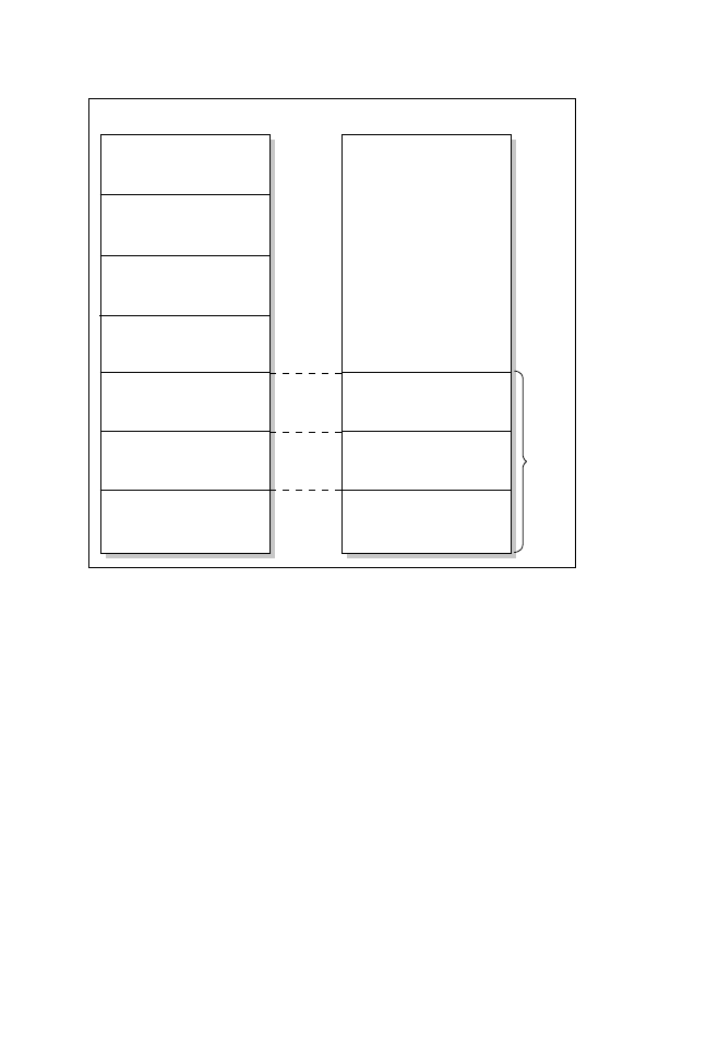
Figure 9.2 displays the PPP model compared to the OSI model.
PPP consists of three main components:
➤ High-Level Data Link Control (HDLC)—Provides for encapsulating datagrams
over PPP links.
➤ Link Control Protocol (LCP)—Establishes, configures, and tests a PPP link.
➤ Network Control Program (NCP)—Configures many different network layer
protocols.
Now that we’ve reviewed PPP basics, let’s configure a simple network imple-
mentation using PPP across an ISDN link.
Application
Presentation
Session
Transport
Network
Data Link
Physical
OSI Model
PPP
IPCP, IPXCP
Network Control Protocol (NCP)
Link Control Protocol (LCP)
Physical
PPP Model
Figure 9.2
The PPP model.

7
○
○
○
○
○
○
○
○
○
○
○
○
○
○
○
○
○
○
○
○
○
○
○
○
○
○
○
○
○
○
○
○
○
○
○
○
○
○
○
○
WAN Technologies
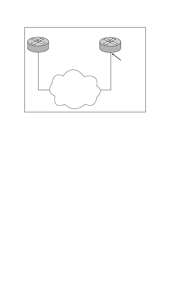
Configuring ISDN on a Cisco Router
Configuring ISDN on a Cisco router requires two main steps:
1. Identify the ISDN switch type in global configuration mode.
2. Configure the desired interface parameters.
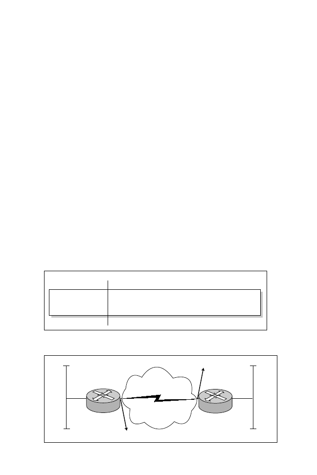
Figure 9.3 shows two Cisco routers connected via an ISDN BRI service. On
Cisco routers, a BRI service is indicated by the interface name of BRI. For PRI
services, the router identifies the service with either T1 (23 B channels) or E1
(For 30 B channels). In this example, router R1 will be configured using the BRI
port on the Cisco router to send user data as required across one B channel, and
the ISDN switch type is basic-net3. We will also be using CHAP authentication.
Listing 9.1 (which is truncated) displays the configuration for router R1.
Note: The BRI interface name is a combination of BRI along with the BRI interface
number (for example, BRI1, BRI2, and so on).
Listing 9.1
The show running-confiig command on R1.
R1#show running-config
version 12.0
hostname R1
enable password 7 1511021F0725
username R2 password cisco
! Define the isdn switch type with the following command
isdn switch-type basic-net3
interface Ethernet0
ip address 10.1.1.1 255.255.255.0
! BRI interfaces are names BRI on a Cisco router
interface BRI0
ip address 131.108.1.1 255.255.255.0
!We are using PPP and PPP authentication
encapsulation PPP
PPP authentication chap
dialer-group 1
dialer map ip 131.108.1.2 name R2 broadcast 0293353020
!
router rip
network 131.108.0.0
! Permit all IP traffic across B channel
dialer-list 1 protocol ip permit
!
line con 0
line vty 0 4
login
8
○
○
○
○
○
○
○
○
○
○
○
○
○
○
○
○
○
○
○
○
○
○
○
○
○
○
○
○
○
○
○
○
○
○
○
○
○
○
○
○
Chapter 9
In the configuration shown in Listing 9.1, the Point-to-Point Protocol is used to
run over the ISDN B-channel. The dialer-group 1 command is associated with the
dialer-list command, which identifies that all IP traffic across the link. This is also
known as defining interesting traffic. Interesting traffic is data that is important enough
to the end user to warrant bringing up the WAN connection. The IOS command
dialer map ip maps the next hop address to router R2 to the Sydney, Australia, ISDN
phone number 0293353020. The router in Listing 9.1 is configured with the broad-
cast routing protocol IP RIP. IP RIP sends all updates as IP broadcasts; hence, the
broadcast keyword used in the dialer map statement. Using IP RIP or any other
broadcast protocol ensures that the BRI link always remains active. Only IP based
traffic will activate the link, and while the link is active, any other protocol may be
carried across the WAN. You use the dialer-list command to advise the router what
protocol, can activate the link. For example, if you wanted to enable IPX to activate
the link (or interesting traffic), you would have to add the following command:
dialer-list 1 protocol ipx permit
Listing 9.2 displays a successful ping from router R1 to router R2 after PPP has
been configured.
Listing 9.2
The ping command on router R1.
R1#ping 131.108.1.2
Type escape sequence to abort.
Sending 5,100-byte ICMP Echos to 131.108.1.2,timeout is 2 seconds:
!!!!!
Success rate is 100 percent(5/5),round-trip min/avg/max=36/36/40ms
R1#
ISDN service provider
switch type is basic-net3
BRI0
131.108.1.1/24
BRI0
131.108.1.2/24
R1
R2
ISDN Number
0293353020
Figure 9.3
ISDN configuration example.

9
○
○
○
○
○
○
○
○
○
○
○
○
○
○
○
○
○
○
○
○
○
○
○
○
○
○
○
○
○
○
○
○
○
○
○
○
○
○
○
○
WAN Technologies
Table 9.1 displays some useful ISDN-related show and debug IOS commands.
PPP multilink is simply the ability to add more B channels together so
that bandwidth is increased from 64Kbps up to 30 B channels or
1.920Mbps.
Now that we have covered ISDN, let’s move onto a protocol that will
enable the least expensive method of allowing communication
between two remote sites, namely Dial on Demand Routing (DDR).
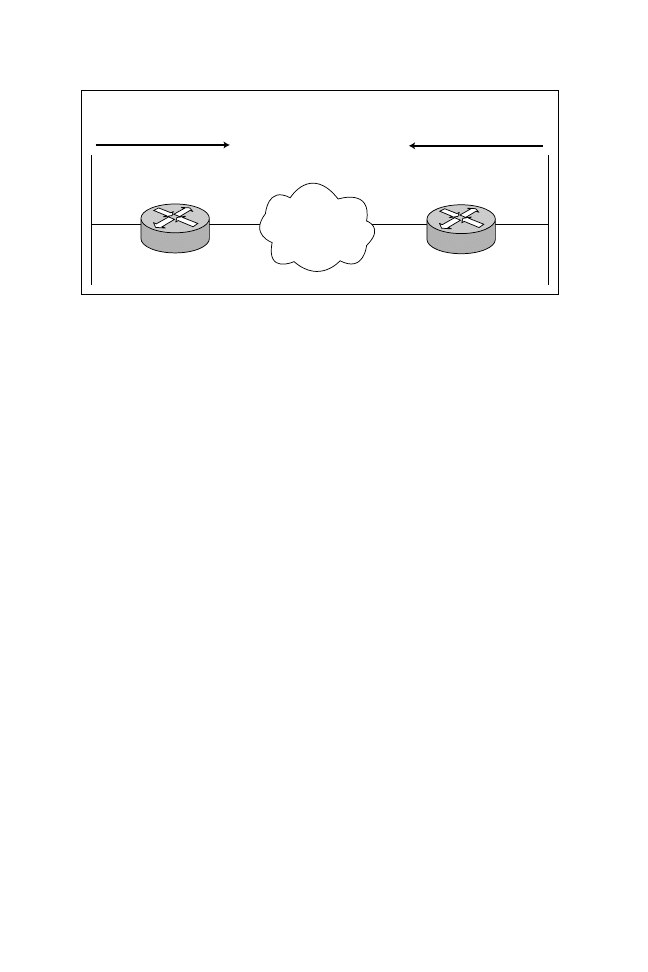
Dial on Demand Routing (DDR)
Dial on Demand Routing (DDR) enables routing information to be initiated
and closed as required by transmitting stations, such as PCs. A DDR link is only
operational when information exchange is required. Typically, DDR is deployed
as a backup connectivity solution in case the primary WAN link goes down.
DDR is used in environments with a low volume of traffic over an ISDN or
Public Switched Telephone Network (PSTN). DDR can also be used as a backup to
a dedicated leased-line service. Figure 9.4 displays a typical situation in which
DDR and dial backup might be used.
Figure 9.4 displays two Cisco routers (named Melanie and Ben) connected over an
ISDN or PSTN line (ISDN would require a BRI interface on the Cisco router, and
PSTN would require an external modem). The routers, Melanie or Ben, have only
low volume traffic to send. DDR can be used to maintain a link between to two
routers when required. This setup results in financial savings over a long period of
time. In general, the process of transferring data between two routers using DDR
goes like this:
1. Traffic defined as interesting arrives at the router forcing the router to acti-
vate the dial up interface in order to transmit the data properly.
Table 9.1
ISDN show and debug commands.
IOS Command
Description
show isdn interface
Displays information on a specific B channel.
show isdn
Displays information about memory, layer 2, and
layer 3 timers.
debug bri
Displays information about ISDN BRI routing activity.
debug isdn events
Displays information about user events that occur on
the interface.
debug isdn q921
Displays layer 2 access procedures.
debug isdn q931
Displays layer 3 information about call setup and call
termination.
10
○
○
○
○
○
○
○
○
○
○
○
○
○
○
○
○
○
○
○
○
○
○
○
○
○
○
○
○
○
○
○
○
○
○
○
○
○
○
○
○
Chapter 9
2. Before data can be transferred between the two routers, the routers must
activate the WAN connection and exchange routing information.
3. After routing information is exchanged, data can be transferred.
4. After the data transfer is complete, a configurable timeout option expires,
and the link disconnects.
As mentioned earlier, DDR can also be used to provide a backup option if a main
leased line goes down due to a carrier or router failure. Figure 9.4 displays a
network that contains a primary link and a backup ISDN link.
Note: Remember, an ISDN service is tariffed according to usage, so ISDN service is
typically only billed when active.
For illustrative purposes, let’s assume the leased line between the Melanie and Ben
routers has failed. Either the Melanie or the Ben routers can bring up the ISDN
service to maintain connectivity. When the leased line becomes active again, the
ISDN line can be brought down. Listing 9.3 displays a sample configuration on the
Melanie router to enable using dial backup.
Listing 9.3
Sample DDR backup configuration.
hostname Melanie
...
interface S0
ip address 1.1.1.1 255.255.255.0
backup interface bri0
backup delay 0 120
backup load 80 50
In the event that the link between the Ben and Melanie routers shown in Figure
9.4 fails, the configuration shown in Listing 9.3 will activate the backup link and
ensure network connectivity between the two sites.
ISDN or PSTN
Melanie
Ben
Low volume data
traffic to Router Ben
Low volume data
traffic to Router Melanie
Figure 9.4
Typical DDR and dial backup application.
11
○
○
○
○
○
○
○
○
○
○
○
○
○
○
○
○
○
○
○
○
○
○
○
○
○
○
○
○
○
○
○
○
○
○
○
○
○
○
○
○
WAN Technologies
In Listing 9.3, the backup interface bri0 command configures the router to use
the BRI0 or ISDN DDR link in case serial0 fails or goes down. The backup
delay 0 120 command tells the router to wait 0 seconds after the main leased line
has failed and before activating the backup connection and then to wait 120
seconds after the main WAN link has been restored before tearing down the
backup link.
Another useful purpose of DDR is to provide extra bandwidth for an
existing circuit in periods of high demand. The backup load 80 50 IOS
command brings up another WAN circuit if the load on an exiting line
reaches 80 percent and brings down the backup link when the existing
load reaches 50 percent.
X.25
X.25 is an international connection-oriented WAN protocol that was developed
in the 1970s to counter high error rates that were occurring across the physical
medium. These high error rates were due to the fact that truly reliable physical
media was not available until the 1980s. Early X.25 networks were designed to
compensate for the unreliable analog circuits with built-in features at layer 2 and
3 that provided error detection and correction. Because X.25 is connection-
orientated, it provides the same features offered by other connection-orientated
service, namely error control and recovery, windowing, and call setup and call
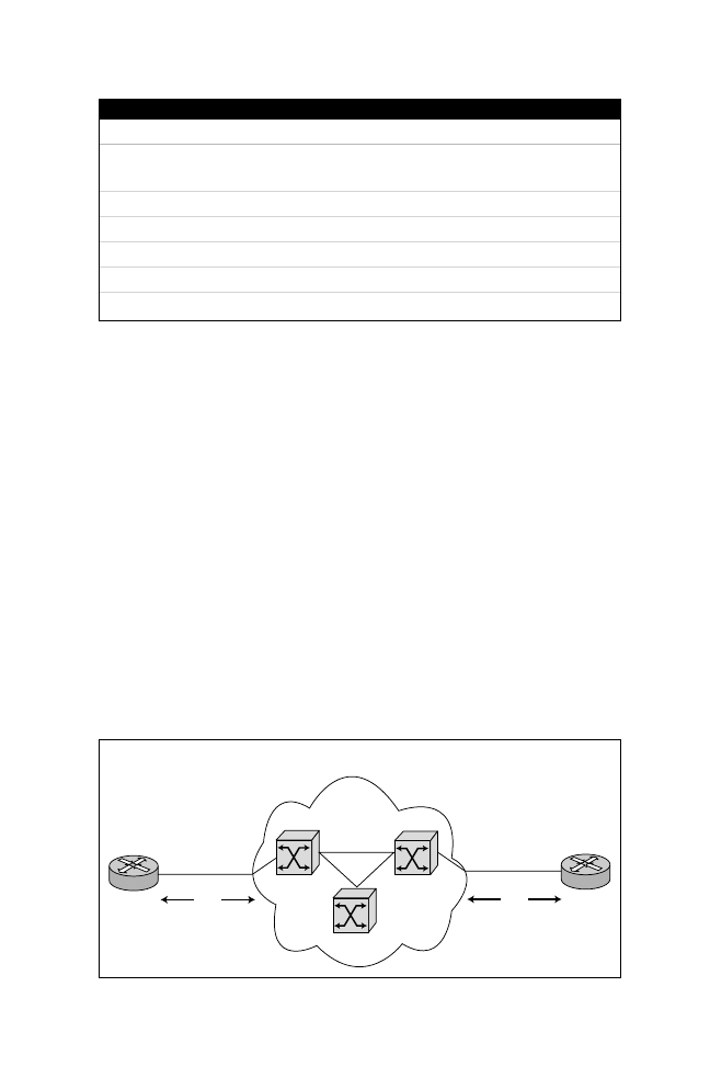
termination. Figure 9.5 shows some of the common elements used in X.25 networks,
and Figure 9.6 shows the X.25 model and how it compares to the OSI model.
A significant point to remember about X.25 is that X.25 was designed
to operate over unreliable physical media. Therefore, it implements
some advanced error checking techniques that allow frames to be
corrected by an X.25 device.
PSE or
PAD switches
X.25 Carrier PAD switches
San Jose
DTE
DCE
Sydney
DTE
DCE
Figure 9.5
X.25 example network.
12
○
○
○
○
○
○
○
○
○
○
○
○
○
○
○
○
○
○
○
○
○
○
○
○
○
○
○
○
○
○
○
○
○
○
○
○
○
○
○
○
Chapter 9
In Figure 9.5, the Cisco router running X.25 encapsulation on its serial interface
acts as the data terminal equipment (DTE). The carrier provides the X.25 switched
backbone or Packet Switching Exchange (PSE), also known as DTE. PSEs transfer
data across the carrier network to the end user network. The packet assembler/
dissembler (PAD) is used to compensate for devices such as PSEs that do not
implement the full functionality of X.25. The protocol running between the data
terminal equipment (DTE) and data communications equipment (DCE) is called
Link Access Procedure Balanced (LAPB). LAPB provides flow control between a
router and an X.25 network, for instance (layer 2 of the X.25 model). The link
between the routers shown in Figure 9.5 could be a service that is permanently
active, which is called a permanent virtual circuit (PVC). On the other hand, you
might want to save on costs by configuring a virtual circuit that is only active when
data traverses the link. This type of connection is known as a switched virtual circuit
(SVC). In addition to providing a cost savings, SVC connections enable service
providers to route around switch failures. As you can see in Figure 9.6, the
layer 3 protocol called Packet-Layer Protocol (PLP) provides addressing for
X.25 devices, and the Physical layer is concerned with how bits are transferred
across the physical wire.
Application
Presentation
Session
Transport
Network
Data Link
Physical
Normal services
provided by
OSI model example,
Telnet or routing
of IP over X.25
PLP
LAPB
X.21bis, RS-232, G-703
E
x
a
m
p
l
e
OSI Model
X.25 Model
X.25
Model
Figure 9.6
The X.25 model.
13
○
○
○
○
○
○
○
○
○
○
○
○
○
○
○
○
○
○
○
○
○
○
○
○
○
○
○
○
○
○
○
○
○
○
○
○
○
○
○
○
WAN Technologies
For example, X.21bis is a physical media specification that provides the electrical
and mechanical properties required for using X.25. Layer 2 of the X.25 model
provides LAPB. PLP manages the exchanges between the DTE and DCE.
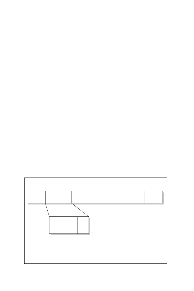
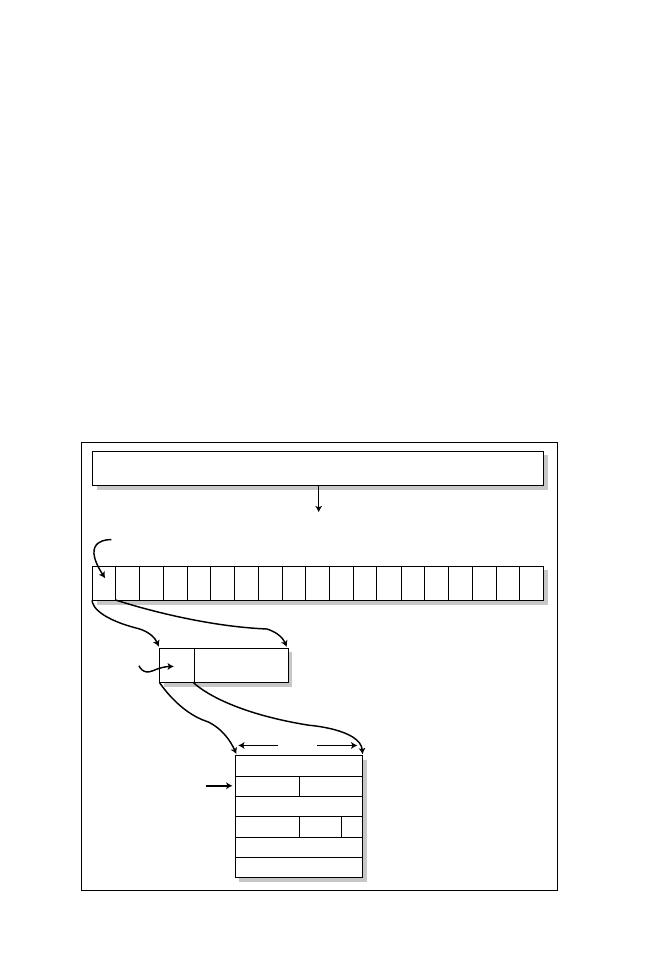
X.25 also has an address called an X.121 address that uniquely identifies each
switch or host. Figure 9.7 shows the format of an X.121 address.
As you can see in Figure 9.7, the X.121 address field includes the International
Data Number (IDN), which consists of two fields—the Data Network Identification
Code (DNIC) and the National Terminal Number (NTN).
Let’s now configure X.25 on a Cisco router in a typical IP environment.
Configuring X.25 on a Cisco Router
The steps required to configure a Cisco router for X.25 depend on the complex-
ity of the design. For a complete guide to configuring X.25, see the “Need to
Know More?” section at the end of this chapter. For the simple network shown in
Figure 9.8, the following steps are required:
1. Configure an X.25 interface.
2. Configure an X.121 address.
3. Map any required protocols, such as IP.
4. Configure any additional X.25 parameters, such as window sizes.
4 digits
DNIC
Up to 10 digits
NTN
Figure 9.7
X.121 address format.
X-25 Cloud
R1
R2
E0
S0
S0
131.108.3.0/50
131.108.1.129/25
131.108.1.1/25
E0
X-121 address is 222
X-121 address is 111
Figure 9.8
X.25 network.

14
○
○
○
○
○
○
○
○
○
○
○
○
○
○
○
○
○
○
○
○
○
○
○
○
○
○
○
○
○
○
○
○
○
○
○
○
○
○
○
○
Chapter 9
Note: Cisco IOS also permits X.25 protocol translation, as discussed in Chapter 10.
X.25 protocol translation enables you to carry X.25 traffic over an IP cloud, for
instance, or enables non-X.25 hosts to communicate to X.25 devices. The IOS
command to configure X.25 translation is translate X25 <x.121 address> tcp <ip
address>. Chapter 10 provides examples of translation commands, as well as a
typical network situation where translation may be applied.
In the network shown in Figure 9.8, you can see that router R1 has one PVC to
router R2. For this example, assume the X.25 carrier has supplied the X.25
address of 111 for R1 and 222 for R2, and IP will run across the X.25 link.
Listings 9.4 and 9.5 show the configurations for routers R1 and R2 on the
serial WAN connection, which will allow IP.
Listing 9.4
Configuring X.25 on router R1.
interface Serial0
ip address 131.108.3.1 255.255.255.252
encapsulation x25
x25 address 111
x25 map ip 131.108.3.2 222 broadcast
Listing 9.5
Configuring X.25 on router R2.
interface Serial0
ip address 131.108.3.2 255.255.255.252
encapsulation x25
x25 address 222
x25 map ip 131.108.3.1 111 broadcast
As you can see in Listings 9.4 and 9.5, the X.25 address is configured with the x25
address IOS command. Also, notice that the PVC in this example’s network happens
to be running over a broadcast link. Therefore, the next hop address must be mapped
using the x25 map ip <next hop address> <remote X.25 address> command. The
broadcast keyword is used to allow protocols such as RIP and IGRP to send and
received broadcast packets. Listing 9.6 shows a successful ping from routers R1
to R2.
Listing 9.6
Pinging across an X.25 link.
R1#ping 131.108.3.2
Type escape sequence to abort.
Sending 5,100-byte ICMP Echos to 131.108.3.2,timeout 2 seconds:
!!!!!
Table 9.2 shows some common X.25 show and debug commands.
15
○
○
○
○
○
○
○
○
○
○
○
○
○
○
○
○
○
○
○
○
○
○
○
○
○
○
○
○
○
○
○
○
○
○
○
○
○
○
○
○
WAN Technologies
Frame Relay
Frame Relay is a high-speed packet-switching WAN protocol that can support
data, audio, and video transmissions. It was primarily developed in response to
improvements made to networks’ physical medium. Frame Relay enables advanced
error checking techniques to be left to the higher layers, which means that Frame
Relay enables layer 2 (Data Link layer) information to be sent rapidly. Contrast this
with X.25, and you can see how speed advances were gained with Frame Relay.
A complete understanding of Frame Relay networks requires you to be familiar
with the technology’s terminology and topology. To help summarize Frame
Relay networks, Figure 9.9 displays a typical Frame Relay carrier design with a
number of Frame Relay switches set up to provide one or more PVCs between
two locations.
We will now describe some of the frequently used terms in a Frame Relay:
➤ Committed Information Rate—The rate at which a Frame Relay network agrees
to transfer information under normal conditions.
Table 9.2
The X.25 show and debug commands.
IOS Command
Description
show x25 map
Displays the X.25 maps in use. Both dynamic and static
mappings are shown.
show x25 vc
Displays X.25 PVCs or SVCs.
show x25 interface
Displays X.25 information on interfaces running X.25.
show cdp interface
Displays interfaces that are running CDP and their parameters.
debug x25 vc
Displays debug information in a virtual circuit setup.
debug x25 interface
Assists in troubleshooting X.25 interfaces.
DLCI
250
Frame relay carrier network switches
San Jose
Sydney
LMI
DLCI 100
LMI
DLCI 100
DLCI
201
DLCI
400
Figure 9.9
Frame Relay terms and topology.
16
○
○
○
○
○
○
○
○
○
○
○
○
○
○
○
○
○
○
○
○
○
○
○
○
○
○
○
○
○
○
○
○
○
○
○
○
○
○
○
○
Chapter 9
➤ Local Port Speed—The maximum speed at which your local interface on a
router can send information.
➤ Committed Burst Rate (B
c
)—The maximum amount of data that a Frame
Relay internetwork is committed to accept and transmit at the CIR.
➤ Excess Burst (B
e
)—The maximum bits a Frame Relay node will attempt to
transmit after the committed burst rate is exceeded.
We will now describe how the Data Link Connection Interface (DLCI) is used
by Frame Relay to identify where a particular frame is sent and how Forward
Explicit Congestion Notification (FECN) and Backward Explicit Congestion
Notification (FECN) messages are used to control congestion. We will also cover
the Discard Eligibility (DE) bit and how Frame Relay switches manage circuits
using Local Management Interface (LMI).
Data Link Connection Identifier (DLCI)
The Data Link Connection Identifier (DLCI) in a Frame Relay network defines
a permanent virtual circuit (PVC) or a switched virtual circuit (SVC). DLCI
values are assigned by the carrier and are only locally significant, because they are
used for mappings within a frame switch. In the example shown in Figure 9.9,
you can see one PVC between the San Jose and Sydney routers. Further, the local
DLCIs supplied by the carrier are 100 each because each Frame Switch can have
the complete range of DLCIs assigned to it. Throughout the carrier cloud, the
carrier determines how a DLCI changes from Frame Switch to Frame Switch..
Figure 9.10 shows how a DLCI is carried in a Frame Relay packet.
1
01111110
Flag
2 to 4
Address Field
Variable
Information Field
2
Frame Check
Sequence
1
01111110
Flag
DLCI FECN BECN DE EA
DLCI – Data Link Connection Identifier
FECN – Forward Explicit Congestion Notification
BECN – Backward Explicit Congestion Notification
DE – Discard Eligibility
EA – Address Field Extension
Field length in bytes
Figure 9.10
Frame Relay frame format (data).

17
○
○
○
○
○
○
○
○
○
○
○
○
○
○
○
○
○
○
○
○
○
○
○
○
○
○
○
○
○
○
○
○
○
○
○
○
○
○
○
○
WAN Technologies
Another feature of Frame Relay is that it implements some congestion control
mechanisms.
Congestion Control Mechanisms
As you can see in Figure 9.10, the address field contains congestion control
mechanisms used in Frame Relay networks. Namely, frame packets can take
advantage of Forward Explicit Congestion Notification (FECN), Backward
Explicit Congestion Notification (BECN), and Discard Eligibility (DE).
Forward Explicit Congestion Notification (FECN)
Forward Explicit Congestion Notification (FECN) is a flag that is used in Frame
Relay networks to control congestion by setting the flag in packets. The FECN
bit is set in the congestion control field in the Frame Relay packet (as shown
earlier in Figure 9.10).
Typically, a Frame Relay service provider will allow a device to burst to a higher rate
than the Committed Information Rate (CIR). The CIR is a rate that is sustainable,
but if the rate is above the CIR rate, FECNs may be used to indicate to a receiving
device that congestion was encountered along the transmission path coming into
the device (that is, forward). FECNs are typically used by the higher layers of the
Frame Relay protocol to slow down data transfer.
Frame Relay traffic shaping is an advanced form of congestion control.
Special queues can be set up to buffer data and send it in regulated
amounts. This results in a mechanism that avoids congestion prob-
lems. Traffic shaping is also used in ATM, which is discussed later in
this chapter.
Backward Explicit Congestion Notification (BECN)
Backward Explicit Congestion Notification (BECN) is also used in Frame Relay
networks to control congestion. The BECN bit is set by a Frame Relay switch
network (remember this device is configured by the carrier) to indicate to the
sending device that frames are traveling in the opposite direction of frames that
are encountering a congested path (that is, away from the device receiving them).
A Frame Relay frame with the BECN bit set in the control field (as shown in
Figure 9.10) is sent from a switch within the carrier’s network toward a router
that is sending a large amount of data. The router receiving this packet will
reduce the rate at which packets are sent out the interface. Remember, Frame
Relay uses frames, not packets.
Discard Eligibility (DE)
The Discard Eligibility (DE) bit is used to indicate which switch frames can be
discarded during periods of high-volume traffic. As with FECN and BECN,

18
○
○
○
○
○
○
○
○
○
○
○
○
○
○
○
○
○
○
○
○
○
○
○
○
○
○
○
○
○
○
○
○
○
○
○
○
○
○
○
○
Chapter 9
the higher layers of the OSI model, which are responsible for ensuring that the
discarded data is re-sent. For example, if FTP frames are discarded during high-
volume traffic congestion, any discarded frames will be re-sent by the source
device and not the Frame Relay network.
Frame Relay does not have any advanced error checking features.
Instead, it deploys a
cyclic redundancy check (CRC). CRC indicates
whether any errors have occurred. If any error has occurred, the
information is simply passed to the higher layers of the OSI model
for resolution.
In addition to providing congestion control mechanisms, Frame Relay also provides
enhanced management features via Local Management Interface (LMI) packets.
Let’s now discuss how a DLCI address is mapped to a Network layer address
using Inverse ARP.
Inverse ARP
Inverse ARP is a protocol within Frame Relay that maps the DLCI, layer 2,
address to the destination IP address, layer 3. This mapping is essential for the
proper operation of Frame Relay. In certain instances, such as when multipoint
subinterfaces are configured, manual mapping must occur. A multipoint interface
(also a software interface) is typically a connection from a central router to many
remote routers. It is sometimes referred to as a hub to spoke routers. This manual
mapping is done via the Frame Relay map command and it will be demonstrated
later in the chapter.
Note: To create a Frame Relay multipoint interface on a high speed serial interface,
you use the IOS command (in interface mode), interface serial <0-0> multipoint.
Local Management Interface (LMI)
Local Management Interface (LMI) is a set of management enhancements made
to Frame Relay. Specifically, LMI offers some advanced management features for
large Frame Relay networks. LMI allows global addressing for DLCIs, and LMI
virtual circuit status messages provide communication between devices in a Frame
Relay network. Further, LMI enables management frames to be sent periodically.
Figure 9.11 shows the LMI frame format.
You are not expected to memorize the LMI frame format, but you need
to be aware that there are two main frame formats in Frame Relay
networks, as illustrated in Figures 9.10 and 9.11.

19
○
○
○
○
○
○
○
○
○
○
○
○
○
○
○
○
○
○
○
○
○
○
○
○
○
○
○
○
○
○
○
○
○
○
○
○
○
○
○
○
WAN Technologies
Cisco routers support three forms of LMI types:
➤ ansi
➤ cisco
➤ q933a
Packet formats vary, although the default LMI type for Cisco routers is cisco.
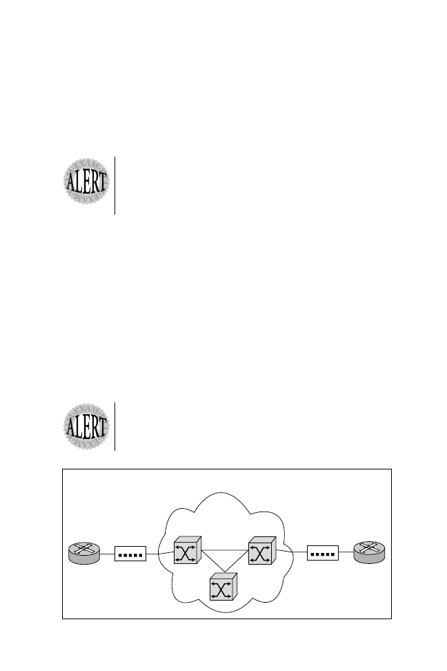
Configuring Frame Relay on Cisco Routers
The steps required to configure a Cisco router for Frame Relay depend on the
complexity of the design. For this example, assume that the simple network shown
in Figure 9.12 has one PVC between each remote site and the central router,
named Simon. Further, subinterfaces (Cisco IOS software interface) will be used
in this section’s configuration example. Basically, subinterfaces are treated by Cisco
IOS as point-to-point links; hence, each PVC requires an IP subnet address for
IP routing.
Note: For a complete guide to configuring Frame Relay networks, refer to the
resources listed in the “Need to Know More?” section at the end of this chapter.
The following steps are required to configure Frame Relay on Cisco routers:
1. Define Frame Relay encapsulation.
2. Define any subinterfaces required.
For our sample configuration, assume that the Frame Relay carrier has provided
us with two pairs of DLCIs. The first pair gives DLCI number 200 to Sharon
and DLCI number 100 to the central router Simon. The second pair gives DLCI
number 300 to Stimpy and DLCI number 400 to the central router Simon.
Listings 9.7 and 9.8 show the configuration setups for the PVCs between Simon,
Sharon, and Stimpy.
1
Flags
2
LMI
DLCI
1
Unnumbered
Information
Indicator
1
Flag
2
POS
Variable
Data
1
Protocol
Destination
1
Call
Reference
1
Nesting
Type
Field length in bytes
Figure 9.11
LMI frame format.
20
○
○
○
○
○
○
○
○
○
○
○
○
○
○
○
○
○
○
○
○
○
○
○
○
○
○
○
○
○
○
○
○
○
○
○
○
○
○
○
○
Chapter 9
Listing 9.7
Configuring Frame Relay on a central router (Simon).
Hostname Simon
...
interface serial 0
encapsulation frame-relay
serial 0.1 point-to-point
Description PVC to Sharon
ip address 131.108.1.1 255.255.255.0
frame-relay interface-dlci 100
interface serial 0.2 point-to-point
Description PVC to Simon
ip address 131.108.2.1 255.255.255.0
frame-relay interface-dlci 400
Listing 9.8
Configuring Frame Relay on remote routers (Sharon and Simon).
Hostname Sharon
...
interface serial 0
encapsulation frame-relay
Frame
Relay
Carrier
Network
Sharon
Stimpy
DLCI 200
DLCI 300
Simon
Local Management
Interface (LMI)
Local Management
Interface (LMI)
Local Management
Interface (LMI)
S0
S0.1 DLCI 100 to
Sharon
S0.2 DLCI 400 to
Stimpy
S0.1
S0.1
Figure 9.12
Frame Relay configuration example.

21
○
○
○
○
○
○
○
○
○
○
○
○
○
○
○
○
○
○
○
○
○
○
○
○
○
○
○
○
○
○
○
○
○
○
○
○
○
○
○
○
WAN Technologies
interface s0.1 point-to-point
Description PVC to Simon
ip address 131.108.1.2 255.255.255.0
frame-relay interface-dlci 200
Hostname Simon
interface serial 0
encapsulation frame-relay
serial 0.1 point-to-point
Description PVC to Simon
ip address 131.108.2.2 255.255.255.0
frame-relay interface-dlci 300
In Listings 9.7 and 9.8, note that DLCI values are locally significant, and using
the description field adds to network documentation for troubleshooting purposes.
If Cisco routers are not configured for subinterfaces, the Frame Relay
map command (or inverse-arp) is important for establishing connec-
tivity over a PVC or SVC. In most situations, Frame Relay inverse arp
will resolve the DLCI to Network layer address for you, but you might
have networks that are not fully meshed. The Frame Relay map
followed by the protocol type allows you to maintain connectivity from
the remote to central location and other remote routers by manually
forcing the mapping as previously discussed.
Table 9.3 lists some common Frame Relay show and debug commands.
Table 9.3
Frame Relay show and debug commands.
Command
Description
show interfaces <serial number>
Displays information about Frame Relay DLCIs and
the LMI operational statistics.
show frame-relay lmi
Displays information about local DLCIs and LMI.
show frame-relay map
Displays information about dynamic (inverse arp)
and statically (Frame Relay map) configured
mappings.
show frame-relay pvc
Displays information about local PVCs and their
DLCI values. Also provides other statistics, such as
FECN, BECN, and DE counts, which are helpful
when troubleshooting.
debug frame-relay lmi
Displays information about local LMI messages
sent and received by a router.
debug frame-relay packet
Displays information about all packets received and
sent by a router.

22
○
○
○
○
○
○
○
○
○
○
○
○
○
○
○
○
○
○
○
○
○
○
○
○
○
○
○
○
○
○
○
○
○
○
○
○
○
○
○
○
Chapter 9
Asynchronous Transfer Mode (ATM)
Asynchronous Transfer Mode (ATM) is a cell-based technology. A cell-based
technology is one that switches cells in hardware. Switching cells in hardware
rather than software means that ATM can achieve high rates of transmission
speeds, from a few Mbps to multi-gigabit speeds.
ATM cells are fixed in length of 53 bytes. This byte size came about due to a
compromise between voice and data experts. Voice experts wanted 32 bytes (ideal
size for voice sampling), and data experts wanted 64 bytes (ideal size for an network
packet). Therefore, to satisfy both sides, the following equation was devised:
32+64=96/2+5 bytes of header gave 53 bytes
As described in Chapter 3, ATM LANE enables legacy networks (such as
Ethernet) to run over ATM and take advantage of the very high bandwidth
speeds available. ATM can switch data, voice, and video.
Let’s now brush up on some ATM terminology.
ATM Terminology
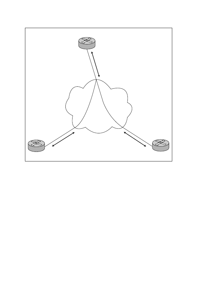
You need to be familiar with the basic details of ATM networks. Figure 9.12
shows a typical ATM environment. In Figure 9.13, three routers (Ren, Simon,
and Norin) are connected to a private ATM network that can consist of Cisco
ATM switches. The ATM connection types between the three routers can be
PVCs or SVCs. As mentioned earlier in this chapter, a PVC is a logical (not
physical) connection between to end points established by a network admin-
istrator. A PVC remains connected and must be torn down manually. An
SVC is a connection that is established prior to data transfer and is only
active for the duration of data transfer. When all end user data has been sent,
the virtual circuit is torn down. SVC requires signaling to set up and remove
virtual circuits (VCs).
ATM devices need to communicate with each other by using some form of signaling
so cells can be sent and received in a timely manner. The signaling used by ATM
devices is called the Interim-Interswitch Signaling Protocol (IISP). ATM devices can
use a number of connection types, including:
➤ Private User Network Interface (UNI)—A connection between private ATM
switches.
➤ Public User Network Interface (PUNI)—A connection between private and
public ATM switches.
➤ Broadband Inter-Carrier Interface (B-ICI)—A connection between public
switches. B-ICIC defines the protocols and procedures needed for establishing,
maintaining, and terminating virtual connections between public networks.
23
○
○
○
○
○
○
○
○
○
○
○
○
○
○
○
○
○
○
○
○
○
○
○
○
○
○
○
○
○
○
○
○
○
○
○
○
○
○
○
○
WAN Technologies
➤ Interim-Interswitch Signaling Protocol (IISP)—A static ATM routing protocol.
It is usually used as a means of interoperability between proprietary and non-
proprietary implementations of PNNI. IISP is formerly known as PNNI phase
0. IISP provides the routes for the purpose of exchanging signaling messages.
➤ Private Network-Network Interface (PNNI)—A specification that describes an
ATM virtual circuit routing protocol, as well as a signaling protocol between
ATM switches.
➤ Network-Network Interface (NNI)—ITU-T-specified standard interface
between nodes within the same network. An example is when the ATM
Forum distinguishes between two standards: one for private networks called
P-NNI and one for public networks known as public NNI.
Keep in mind that cell formats vary slightly for each type of connection (as
discussed later in this chapter). Other key ATM network elements you need to
be familiar with include:
➤ Interim Local Management Interface (ILMI)—Used between ATM devices,
which enables administrators to incorporate network-management capabilities
into an ATM UNI connection.
➤ Service Specific Connection Oriented Protocol (SSCOP)—A data link protocol
that guarantees the delivery of ATM signaling packets.
Ren
Norin
Private
NNI
Public
NNI
Other Carriers
B-ICI
Public UNI
Public ATM
Network typically
a Carriers Network
ILMI
Private
UNI
Private UNI
Public
UNI
Simon
Private
ATM Network
ILMI
Private
UNI
Figure 9.13
ATM terminology.

24
○
○
○
○
○
○
○
○
○
○
○
○
○
○
○
○
○
○
○
○
○
○
○
○
○
○
○
○
○
○
○
○
○
○
○
○
○
○
○
○
Chapter 9
➤ Interim-Interswitch Signaling Protocol (IISP)—An ATM signaling protocol
used for interswitch communication.
Before moving on to look at ATM quality of service (QoS) and ATM cell formats,
let’s briefly discuss the two RFCs that define how network data can be sent over
ATM networks—RFC 1483 and RFC 1577.
RFC 1483
RFC 1483 defines muliprotocol encapsulation over ATM. Namely, this RFC
defines the following two methods of carrying traffic over ATM:
➤ Single VC Protocol—One network protocol is carried over a virtual circuit.
➤ LLC/SNAP Encapsulation—Multiple protocols can be sent over a single vir-
tual circuit.
Unlike RFC 1577, RFC 1483 does not require an Address Resolution
Protocol (ARP) server. ATM devices maintain their own ARP tables,
which map IP addresses to ATM addresses.
RFC 1577
RFC 1577 defines how IP will be carried across an ATM circuit. An Address
Resolution Protocol (ARP) server maintains IP and ATM address mappings in
an ARP table. ATM devices will establish a circuit to the ARP server for any
address mapping required.
Quality Of Service (QoS)
ATM offers a number of service categories that can be used to maintain quality of
service between two end devices. Typically, a carrier will supply a service, and the
network administrator ensures that the limits (or quality of service) are not breached;
this is referred to as policing (otherwise, cells might be dropped by the carrier).
Policing is a method for the service provider to enforce QoS on their access port.
Services supplied by carriers fall into four main service categories:
➤ Available Bit Rate (ABR)—Allows traffic to be sent at the rate at which band-
width is available. Typically, ABR is used for bursty traffic, like data networks.
‰
Constant Bit Rate (CBR)—Guarantees that traffic will be sent in a con-
stant fashion. Typically, CBR is used in video or voice applications where cells
cannot be dropped without degradation. Cell loss and delay must be low to
mai0ntain video and voice quality.
➤ Unspecified Bit Rate (UBR)—Allows traffic to be sent as required but does
not guarantee delivery. Typically, UBR is used for data traffic.

25
○
○
○
○
○
○
○
○
○
○
○
○
○
○
○
○
○
○
○
○
○
○
○
○
○
○
○
○
○
○
○
○
○
○
○
○
○
○
○
○
WAN Technologies
➤ Variable Bit Rate (VBR)—Provides a limited amount of bandwidth. VBR is
useful for packet video and voice transmissions.
Some of the traffic parameters carriers can limit on a service include:
➤ Peak Cell Rate (PCR)—Maximum rate a connection can withstand without
losing cells.
➤ Sustainable Cell Rate (SCR)—The average ATM cell throughput permitted
by the carrier.
➤ Maximum Burst Size (MBS)—The maximum possible cell transmission rate.
➤ Minimum Cell Rate (MCR)—The minimum cell transmission rate that can
be maintained.
The next section briefly looks at the most common cell format used in data
network—AAL5.
ATM Cell Format
The most common cell format used in data networks is the ATM Adaptation
Layer 5 (AAL5) cell format. The ATM Adaptation layer is one of the lower
three layers of the ATM model (see Figure 9.14).
Convergence
Sublayer
Segmentation and
Preassembly Sublayer
Cell Header Creation
and Removal
VPI/VCI Transation
Flow Control
Physical Media
Examples
VTP, STP,
Fiber Coax
ATM Model
Higher layer
services,
such as LANE
and user services
ATM Adaption Layer
(ATM Cells Conversion)
ATM Layer
(Cell Relaying and Multiplexing)
Physical Layer
(Framing, Connection Types)
CS
SAR
Figure 9.14
ATM model.
26
○
○
○
○
○
○
○
○
○
○
○
○
○
○
○
○
○
○
○
○
○
○
○
○
○
○
○
○
○
○
○
○
○
○
○
○
○
○
○
○
Chapter 9
ATM adaptation is a process where data is received by an end device and then
cells are created for delivery across the ATM layer. The ATM layer then passes
the cells to the Physical layer where cells are switched at high rates. Figure 9.15
displays the AAL5 cell format.
Referring to the ATM cell format shown in Figure 9.15, the VPI/VCI pair is
used to indicate which PVC or SVC this ATM cell will be sent to.
The PT is used to indicate the payload type. One bit in the PT field is used to
indicate the last cell. ATM cells must be received in the order they are received so
that the end device can reassemble the packet or frame in the correct order. ATM
does not provide resources to renumber cells in the correct order in the event a cell
is transmitted out of order. ATM cannot reassemble cells that are sent out of order.
The CLP bit is used to indicate whether the cell can be dropped in peak periods.
The CLP bit is analogous to the DE bit in Frame Relay.
The HEC is a simple error checking mechanism used to check for errors in the
header fields only.
End User Data
Cells are
created by AAL5
Cells (48 bytes)
Cell header
5 bytes
Data
(48 bytes)
VPI
VCI
HEC
User data
VPI
VCI
VCI
PT
CLP
ATM header
(5 bytes)
8 bytes
(12 bits) VPI – Virtual Path Identifier
(16 bits) VCI – Virtual Channel Identifier
(3 bits)
PT – Payload Type
(1 bit)
CLP – Cell Loss Priority
(8 bits)
HEC – Header Error Control
Figure 9.15
ATM cell format

27
○
○
○
○
○
○
○
○
○
○
○
○
○
○
○
○
○
○
○
○
○
○
○
○
○
○
○
○
○
○
○
○
○
○
○
○
○
○
○
○
WAN Technologies
If a data packet has be broken into cells by the ATM Adaptation layer
and sent to the destination and one single cell has become corrupted,
the entire data packet must be re-sent by the higher network layers
(such as TCP).
Configuring ATM on Cisco Routers
The complexity of ATM presents a wide range of configuration options. The full
set of options is too large to present in this book. If you would like to study some
advanced ATM networking theory, refer to the references listed in the “Need to
Know More?” section at the end of this chapter.
Up to this point in the chapter, we’ve looked at some of the most common WAN
protocols and WAN services provided by carrier companies. Let’s now briefly
look at some terms you may encounter in the CCIE program.
Physical Layer Standards
You need to be aware of a number of standards. You are not expected to memorize
the full Physical layer standard, but you should understand some of the physical
standards you may come across and then describe a typical application. To help you
to prepare, here are some Physical layer related terms:
➤ Synchronization—Establishes timing information between a sender and a
receiver so that information flow can occur.
➤ Synchronous Optical Network (SONET)—Defines a high-speed (up to 10Gbps)
synchronous network specification that was developed by Bellcore and designed
to run on optical fiber. Examples include STS-1, which operates at 51.84 Mbps,
and STS-3c, which operates at 155.52Mbps. ATM can use SONET as the
Physical layer connection between switches.
➤ T1—Provides a link between two devices running at 1.544Mbps. T1 lines are
widely used in North America.
➤ E1—Provides a link that can send data at a rate of 2.048Mbps. E1 lines are
widely used in Europe and Australia.
➤ Encoding—Modifies information into a required transmission format.

28
○
○
○
○
○
○
○
○
○
○
○
○
○
○
○
○
○
○
○
○
○
○
○
○
○
○
○
○
○
○
○
○
○
○
○
○
○
○
○
○
Chapter 9
Practice Questions
Question 1
What IOS command will display the interface statistics on a BRI interface on
a Cisco 2503 router?
❍ a. show interfaces bri
❍ b. show interfaces ISDN
❍ c. show interfaces bri0
❍ d. show interfaces bri1
The correct answer is c. A Cisco 2503 router has one Ethernet interface, two
high-speed serial interfaces, and one BRI interface. The command used to view
the interface statistics on a Cisco ISDN B channel is show interface bri0. An-
swer a is incorrect, because this command does not indicate the 0 key digit. An-
swers b and d are incorrect, because they present invalid IOS commands.
Question 2
What services can be carried by an ISDN service?
❍ a. Voice
❍ b. Data
❍ c. Video
❍ d. All of the above
The correct answer is d. ISDN can support voice, data, and video. Answers a, b,
and c are incorrect, because ISDN carries all the services listed in the answers.

29
○
○
○
○
○
○
○
○
○
○
○
○
○
○
○
○
○
○
○
○
○
○
○
○
○
○
○
○
○
○
○
○
○
○
○
○
○
○
○
○
WAN Technologies
Question 3
What IOS command is required to set a serial interface on a Cisco router to
X.25 encapsulation? [Choose the two best answers]
❑ a. encap x25
❑ b. encapsulation x.25
❑ c. encapsulation x25
❑ d. interface x25
The correct answers are a and c. The set a Cisco router’s encapsulation to X.25,
the keyword in interface mode is encapsulation or encap, as shown in answers a
and c. Answer b is incorrect, because, when setting encapsulation to X.25, the
correct keyword is X25 and not X.25. Answer d is incorrect, because interface
x25 is an invalid IOS command.
Question 4
The dialer map ip 131.108.1.2 name R2 broadcast 0293353020 IOS com-
mand maps an IP address to a calling party number. What is the next hop
address in this configuration?
❍ a. 131.108.1.1
❍ b. 131.108.1.2
❍ c. 131.108.0.0
❍ d. Not enough information provided
The correct answer is b. The dialer map command is used to map the next hop IP
address to the ISDN phone number required to connect to that next hop. Answer
a is incorrect, because 131.108.1.1 is not the correct IP address configured in the
dialer-map command. Answers c is incorrect, because 131.108.0.0 is an invalid
next hop address or host address. Answer d is incorrect, because there is enough
information to answer the question correctly.

30
○
○
○
○
○
○
○
○
○
○
○
○
○
○
○
○
○
○
○
○
○
○
○
○
○
○
○
○
○
○
○
○
○
○
○
○
○
○
○
○
Chapter 9
Question 5
What is a FECN?
❍ a. Not used in Frame Relay.
❍ b. Used in ISDN only.
❍ c. A bit in a frame that informs a DTE receiving the frame that
congestion was experienced in the path from source to destination.
❍ d. A bit in a frame traveling in the opposite direction of frames
encountering a congested path.
The correct answer is c. Forward Explicit Congestion Notification (FECN) is
used in a Frame Relay environment to inform the DTE receiving the frame that
congestion was experienced. Answers a and b are incorrect, because FECNs are
used in Frame Relay environments. Answer d is incorrect, because it describes
Backward Explicit Congestion Notification (BECN).
Question 6
A DDR circuit is typically used in what type of network situation?
❍ a. When data must be sent continually.
❍ b. When data must be sent on average every 90 seconds.
❍ c. When data must be sent as required but the WAN link remains idle
when no data is sent.
❍ d. Can only be used with IP data
The correct answer is c. Dial on Demand Routing (DDR) is used to send data over
a WAN line only when necessary. When no data is sent across the WAN link (or it
is idle), the circuit is closed to save on usage costs. Answer a is incorrect, because
data that must be sent consistently should be sent across a leased line that is active
all the time. Answer b is incorrect, because DDR is used whenever transmission is
required by user, not every 90 seconds. Answer d is incorrect, because DDR can be
used with other network protocols such as IPX, DECnet, and AppleTalk.

31
○
○
○
○
○
○
○
○
○
○
○
○
○
○
○
○
○
○
○
○
○
○
○
○
○
○
○
○
○
○
○
○
○
○
○
○
○
○
○
○
WAN Technologies
Question 7
How long are ATM cells?
❍ a. 53 bits
❍ b. 53 bytes
❍ c. 48 bits
❍ d. 48 bytes
❍ e. 5 bytes
The correct answer is b. An ATM cells is 53 bytes in length. Answers a, c, d, and
e are incorrect, because they provide incorrect sizes.
Question 8
Which of the following are valid X.121 addresses? [Choose the two best
answers]
❑ a. 00c0-6789-1234
❑ b. 121
❑ c. 121. 00c0-6789-1234
❑ d. 123456
The correct answers are b and d. An X.121 address can be any digit in length if
supported by the X.25 switches. Answers a and c are incorrect, because an X.121
address is made up numeric numbers and do not include dashes or periods.
Question 9
Frame-Relay Inverse ARP maps what to what?
❍ a. IP to a MAC address
❍ b. MAC address to an IP address
❍ c. DLCI value to a Network layer address
❍ d. There is no such process in Frame Relay
The correct answer is c. Frame Relay inverse ARP is used to map a Local DLCI
value to a Network Address. Answer a is incorrect, because MAC addresses are

32
○
○
○
○
○
○
○
○
○
○
○
○
○
○
○
○
○
○
○
○
○
○
○
○
○
○
○
○
○
○
○
○
○
○
○
○
○
○
○
○
Chapter 9
not used to map to a DLCI address in a Frame Relay network. Answer b is
incorrect, because the process of mapping a MAC address to an IP address is IP
ARP. Answer d is incorrect because Inverse ARP is used in Frame Relay net-
works to ensure network layer connectivity.
Question 10
What is X.25’s most important feature?
❍ a. Poor physical cabling means X.25 cannot be used.
❍ b. X.25 is not an international standard.
❍ c. X.25 provides a connection-orientated service.
❍ d. Provides no error checking techniques.
The correct answer is c. X.25 was designed to provide connection-oriented ser-
vices because of the poor standard and the quality of physical cabling. By guaran-
teeing data across a network, X.25 become widely used in the 1970s and 1980s.
Answers a is incorrect, because X.25 is designed to run over poor cabling systems.
Answer b is incorrect, as X.25 is a recognized international standard. Answer d is
incorrect, because X.25 provides not only error checking techniques but also
windowing, flow control, and data recovery.
Question 11
You are running HDLC encapsulation between two Cisco routers (R1 and
R2) over a Wide Area Link. Host 1 resides on R1 and Host 2 resides on R2. A
frame is sent from Host 1 to Host 2, and an error occurs on the WAN link
between the two Cisco routers. What device will retransmit the frame?
❍ a. R1
❍ b. R2
❍ c. Host 1
❍ d. Host 2
The correct answer is c. HDLC does not provide a connection-oriented service.
Any frames lost or corrupted during delivery must be retransmitted by the origi-
nating device. When Host 1 sends a packet and an error occurs across the WAN,
the Cisco routers will not retry transmission, but Host 1 will eventually retry
when there is no response or reply from Host 2. This leaves answers a, b and c as
incorrect choices.

33
○
○
○
○
○
○
○
○
○
○
○
○
○
○
○
○
○
○
○
○
○
○
○
○
○
○
○
○
○
○
○
○
○
○
○
○
○
○
○
○
WAN Technologies
Question 12
What encapsulation method is used on the following interface?
ATM5/0 is up, line protocol is up
Hardware is ENHANCED ATM PA
Description Simon's router to SanJose
MTU 1500 bytes, sub MTU 1500,
BW 4500 Kbit, DLY 200 usec,
reliability 255/255, txload 45/255,
rxload 41/255
Encapsulation ATM, loopback not set
Keepalive not supported
Encapsulation(s): AAL5
4096 maximum active VCs, 2 current VCCs
VC idle disconnect time: 300 seconds
0 carrier transitions
Last input 00:00:00, output 00
...
❍ a. ATM
❍ b. PPP
❍ c. Frame-relay
❍ d. Not enough data
The correct answer is a. The display shown in the question clearly identifies the
interface to be an ATM hardware interface with the line, Hardware is EN-
HANCED ATM PA and the other giveaway is the line, Encapsulation ATM.
This question is designed not to test your ability to read, but your familiarity with
IOS output displays. You should be able to recognize any WAN or LAN inter-
face display. Answers b, c and d are therefore incorrect.

34
○
○
○
○
○
○
○
○
○
○
○
○
○
○
○
○
○
○
○
○
○
○
○
○
○
○
○
○
○
○
○
○
○
○
○
○
○
○
○
○
Chapter 9
Need to Know More?
Chappell, Laura. Advanced Cisco Router Configuration (ACRC).
Macmillan Publishing Company, Indianapolis, IN, 1998. ISBN 1-
57870-074-4. Part 4 of the book details WAN connectivity and in-
cludes some quality examples.
Cisco IOS 12.0 Wide Area Networking. Cisco Press, Indianapolis, IN,
1999. ISBN 1-57870-158-9. This book provides all the configurable
options available with Cisco IOS. Each chapter provides a brief intro-
duction followed by all the IOS command options. The book is an
excellent resource on the WAN technologies available on Cisco rout-
ers. Chapters 1 and 2 concentrate on ATM, followed by Chapter 3
and 4 that cover Frame Relay configurations. X.25 is covered in Chap-
ters 7 and 8. The content is also available on the Cisco documentation
CD or online on Cisco documentation home page www.cisco.com/
univercd/home/home.htm.
Wyszukiwarka
Podobne podstrony:
433 8C03 6D5LOD4KUALBGAZYU2BPHU Nieznany
433 8C06 IUPZAHYZLTJ5FVC5ASSTC7 Nieznany
433 8C08 CCONPVVGMRFKY3H2SV6MLO Nieznany
433 8C02 JQVRRLWPBK322K7TFJA45L Nieznany
433 8C05 CWJ323BUNESSWSM7ARIJUO Nieznany
433 8C10 3FPMCIVQISRE4NQU7HR5KM Nieznany (2)
433 8C04 NMVY43YFSQAYQTRGRSPPKV Nieznany
433 8C07 DQEIPY2FHEXNFWINPZ4QPR Nieznany
KPG 433 12 id 249386 Nieznany
4 kanaly Remote Control UHF 433 Nieznany (2)
Gor±czka o nieznanej etiologii
02 VIC 10 Days Cumulative A D O Nieznany (2)
Abolicja podatkowa id 50334 Nieznany (2)
45 sekundowa prezentacja w 4 ro Nieznany (2)
4 LIDER MENEDZER id 37733 Nieznany (2)
Mechanika Plynow Lab, Sitka Pro Nieznany
więcej podobnych podstron