
1
○
○
○
○
○
○
○
○
○
○
○
○
○
○
○
○
○
○
○
○
○
○
○
○
○
○
○
○
○
○
○
○
○
○
○
○
○
○
○
○
○
○
○
○
○
○
○
○
7
Networking and
Desktop Protocols
Terms you’ll need to understand:
✓ Internetwork Packet Exchange (IPX)
✓ Routing Information Protocol (RIP)
✓ NetWare Link State Protocol (NLSP)
✓ Enhanced Interior Gateway Routing Protocol (EIGRP)
✓ AppleTalk
✓ Routing Table Maintenance Protocol (RTMP)
✓ AppleTalk EIGRP
✓ DECnet
✓ OSI
✓ NetBIOS
✓ NetBEUI
✓ Windows Internet Naming Service (WINS)
✓ Dynamic Host Configuration Protocol (DHCP)
Techniques you’ll need to master:
✓ Describing how desktop protocols function
✓ Explaining the routing mechanisms for desktop protocols
✓ Managing and configuring desktop support on
Cisco routers
✓ Explaining how Windows clients browse a network

2
○
○
○
○
○
○
○
○
○
○
○
○
○
○
○
○
○
○
○
○
○
○
○
○
○
○
○
○
○
○
○
○
○
○
○
○
○
○
○
○
Chapter 7
This chapter describes some of the more commonly used desktop protocols, with
an emphasis on topics covered in the CCIE Routing and Switching exam. The
following CCIE blueprint objectives, as defined by the Cisco Systems CCIE
program, are covered:
➤ Internetwork Packet Exchange (IPX)—NetWare Link Services Protocol
(NLSP), IPX RIP, IPX Service Advertising Protocol (SAP), IPX EIGRP,
Sequenced Packet Exchange (SPX), Network Control Protocol (NCP),
IPXWAN, IPX addressing, get nearest server (GNS) requests, Novell Direc-
tory Services (routing and mechanisms), access lists
➤ AppleTalk—Routing Table Maintenance Protocol (RTMP), AppleTalk Up-
date-Based Routing Protocol (AURP), AppleTalk EIGRP, Datagram Deliv-
ery Protocol (DDP), Zone Information Protocol (ZIP), Name Binding
Protocol (NBP), addressing (phases 1 and 2), access lists
➤ DECnet/OSI—Addressing, access lists
➤ Windows NT—NetBIOS, browsing, domain controller (such as WINS), ac-
cess lists
As with other chapters in this book, additional information is provided for complete-
ness and in preparation for additional subjects as the CCIE program expands.
Internetwork Packet Exchange (IPX)
Novell released IPX in 1980. IPX was very popular, but it was primarily designed
for local area networks (LANs). The IPX protocol is based on service advertise-
ments, called service access point (SAP). When Cisco routers are deployed in IPX
networks, they offer increased capabilities that are not usually available. For ex-
ample, Cisco routers can forward specific IPX broadcasts that allow serverless
IPX LANs to function normally. In this chapter, we will discuss the role of Cisco
routers and operation of IPX in greater detail.
IPX servers and printers send out SAPs (which are broadcast frames), and Cisco
routers listen for the SAPs and install them into a SAP table. For example, when
a PC, running IPX attempts to connect to a server, it sends out a request called a
get nearest server (GNS) request. If there are any local servers, they respond to the
PC’s GNS request. If there are no IPX servers on the local network, the Cisco
router responds instead. The client PC then makes a direct connection request to
the local or remote server through the Cisco router.
Keep in mind that GNS requests are sent as broadcast frames, and excessive
broadcasts reduce bandwidth for end users. Later in this chapter, we’ll examine
how to manage GNS requests and SAPs.

3
○
○
○
○
○
○
○
○
○
○
○
○
○
○
○
○
○
○
○
○
○
○
○
○
○
○
○
○
○
○
○
○
○
○
○
○
○
○
○
○
Networking and Desktop Protocols
NetWare Protocol Suite
At this point, let’s take a look at the NetWare protocol suite (shown in Figure 7.1)
and how Novell’s implementation of a proprietary protocol relates to the OSI
model. As you can see in Figure 7.1, the Novell protocol suite provides applica-
tion services through NetBIOS, the NetWare shell determines whether the ap-
plication requires network services. The routing protocol used by Novell by default
is IPX RIP Let’s discuss each layer and associated protocols of the IPX model.
Application Layer (NCP)
The higher layers of IPX (layers 5 through 7) provide end users with the ability to
view files on servers. NetWare Core Protocol (NCP) is used to send and receive
files, send print jobs, and provide security. These are just some of NCP’s major
functions that are performed by the Application layer of the IPX protocol suite.
The service access point application protocol rests on top of IPX and is used to
advertise IPX services, such as file servers and printers. SAPs are sent as broad-
casts, so if you have a lot of servers and printers, you can significantly increase
your broadcast traffic. SAP services are identified in the IPX packet. For ex-
ample, the file server SAP has a type code 4, and printers have a type code 7. A
complete list of all the SAP codes is available on Novell’s Web site (search for the
keyword SAP on www.novell.com).
Application
Presentation
Session
Transport
Network
Data Link
Physical
IPX Protocol Suite
NetBIOS,
NetWare
shell
SPX
Routing Protocol,
IPX RIP, NLSP
EIGRP
IPX
Ethernet, Token Ring, FDDI,
Frame Relay, PPP, and more
OSI Model
Applications such as Network
Control Protocol (NCP) and
Service Access Point (SAP)
Figure 7.1
NetWare protocol suite.

4
○
○
○
○
○
○
○
○
○
○
○
○
○
○
○
○
○
○
○
○
○
○
○
○
○
○
○
○
○
○
○
○
○
○
○
○
○
○
○
○
Chapter 7
Transport Layer (SPX)
The Transport layer uses the Sequenced Packet Exchange (SPX) protocol in the IPX
model. SPX provides reliable services and is connection-orientated. SPX is simi-
lar to TCP because of its ability to provide reliable connection-oriented services.
Network Layer (IPX)
The IPX Network layer provides each device with a unique network layer address
used to reach local and remote networks. IPX is connectionless. Like any routable
protocol, there must be some form of addressing. IPX addressing is unique in that
it provides for almost three times as many possible addresses as IP addressing.
An IPX address is made up of 80 bits. The first 32 bits identify the network, and
the next 48 bits are taken from the MAC address. Together, these create an IPX
address. Having all these SAPs and addresses is a benefit of IPX, however, the
next question is how does IPX route all this across the wide area network (WAN)?
To populate the IPX routing table so that routers can route IPX traffic across the
WAN, Cisco routers can use the following protocols:
➤ IPX RIP—IPX Routing Information Protocol
➤ IPX NLSP—IPX NetWare Link State Protocols
➤ IPX EIGRP—IPX Enhanced Interior Gateway Routing Protocol
NLSP is the latest implementation used to address the concerns of IPX RIP,
such as poor convergence times and hop count limits. IPX RIP supports a maxi-
mum hop count of only 15 hops, whereas IPX NLSP supports up to 127 hops.
Therefore, IPX NLSP is more scalable because the increased hop count allows
for a greater network diameter. NLSP is a link-state protocol, which means an
administrator can take advantage of all the qualities of link-state protocols as
opposed to distance-vector protocols. These qualities include faster convergence
after a network change and NLSP’s support for hierarchical network design, which
allows for networking devices to be grouped into areas and domains. There is no
need to use an Address Resolution Protocol (ARP), because the node address is
taken from the unique MAC address.
Note: The node portion of an IPX address (the last 48 bits) on a serial interface is
taken from a LAN interface, because serial interfaces do not have a MAC address.
This portion of the IPX address is taken from the first active Ethernet, Token Ring,
and then FDDI interfaces.
Data Link and Physical Layer
The Data Link and Physical layers are designed to provide physical connectivity
at an electrical level, that is the Physical layer, and they provide a reliable transit
of data across the Physical layer, that is the Data Link layer. IPX can run over

5
○
○
○
○
○
○
○
○
○
○
○
○
○
○
○
○
○
○
○
○
○
○
○
○
○
○
○
○
○
○
○
○
○
○
○
○
○
○
○
○
Networking and Desktop Protocols
many LAN technologies, such as Ethernet and Token Ring. Further, IPX can run
over wide area networks, such as Frame Relay and Point-to-Point Protocol (PPP).
Let’s now look at how IPX is routed and configured on a Cisco router using the
three available options—IPX RIP, IPX NLSP, and IPX EIGRP.
Routing Information Protocol (RIP)
The Routing Information Protocol designed for IPX is a distance-vector protocol
that uses hop counts and ticks as the metric. Remember, a tick is a measure of delay
on an interface. IPX RIP will load balance if the hops and tick count are the same.
Let’s examine the configuration tasks on a Cisco router and the available show
commands used to monitor and verify proper operation of IPX. By default, Cisco
IOS runs IPX RIP unless configured otherwise. To enable IPX RIP routing, you
simply type the following command in global mode:
ipx routing
Like IP, you then configure network addressing on the interface that will run
IPX. This is completed with the following IOS command:
ipx network <network number> encapsulation <encapsulation type>
IPX RIP supports a number of encapsulation types. Table 7.1 shows the options
available on Cisco routers.
If no encapsulation is entered when you configure a Cisco router interface for
IPX, novell-ether for Ethernet and sap for Token Ring are the encapsulation
types set by default.
The main features of IPX RIP are that it’s a distance-vector protocol,
and the metric is based on ticks and hop counts. The maximum hop
count is 15. IPX RIP periodically sends out updates every 60 seconds.
Do not confuse this interval with the IP RIP update interval, which is
30 seconds.
Table 7.1
Cisco encapsulation options.
Media
Cisco Name
Novell Name
Ethernet
novell-ether
Ethernet_802.3
sap
Ethernet_802.2
arpa
Ethernet_II
snap
Ethernet_Snap
Token Ring
sap
Token-Ring
snap
Token-Ring_Snap
6
○
○
○
○
○
○
○
○
○
○
○
○
○
○
○
○
○
○
○
○
○
○
○
○
○
○
○
○
○
○
○
○
○
○
○
○
○
○
○
○
Chapter 7
IPX RIP Configuration Task List
Now, let’s examine the configuration of a simple IPX network using IPX RIP.
Later in this chapter, we’ll use the same network to demonstrate using NLSP
and EIGRP to route IPX.
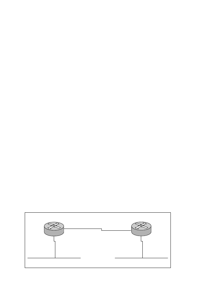
As you can see in Figure 7.2, there are two routers—R1 and R2. Both routers
have a local IPX segment. In this section, you’ll apply the default encapsulation
on all segments to novell-ether (which means that no additional configuration is
required because novell-ether is the default). Listing 7.1 displays the configura-
tion required on both routers.
Listing 7.1
IPX configuration on routers R1 and R2.
hostname R1
ipx routing 0000.0c75.d97e
interface Ethernet0
ipx network 1
interface Serial0
ipx network BAD
....
hostname R2
ipx routing 0000.0c8e.774b
interface Ethernet0
ipx network 2
interface Serial0
ipx network BAD
....
Note: In Listing 7.1, notice that the IPX network number on the serial link is the
same. If the network numbers were different, the two routers would not share IPX
routing information.
Listing 7.2 shows the IPX routing table on router R1 by using the command
show ipx route.
IPX Network 1
E0
IPX Network 2
S0
E0
S0
IPX Network BAD
R1
R2
Figure 7.2
A simple IPX network configuration task.

7
○
○
○
○
○
○
○
○
○
○
○
○
○
○
○
○
○
○
○
○
○
○
○
○
○
○
○
○
○
○
○
○
○
○
○
○
○
○
○
○
Networking and Desktop Protocols
Listing 7.2
The show ipx route command on the R1.
R1#sh ipx route
Codes: C - Connected primary network,c-Connected secondary network
S - Static, F - Floating static, L - Local (internal),
R - RIP, E - EIGRP, N - NLSP, X - External, A - Aggregate
s - seconds, u - uses
3 Total IPX routes. Up to 1 parallel paths and 16 hops allowed.
C 1 (NOVELL-ETHER), Et0
C BAD (HDLC), Se2
R 2 [07/01] via BAD.0000.0c8e.774b, 4s, Se0
As you can see in Listing 7.2, the IPX routing table is very similar to an IP
routing table. The table displays, which IPX networks, are reachable locally (C)
and remotely (R). The network highlighted in Listing 7.2 has been discovered
dynamically using the IPX RIP (indicated by the letter R) protocol. The delay
and hop count is described in square brackets [07/01], where 07 is the delay, 01 is
the hop count. The next hop address is indicated as BAD.0000.0c8e.774b via
Serial 0 (Se0). On R1 in Listing 7.2, you can see that the remote IPX network
number 2 is reachable via the serial 0 interface. Notice also that the network was
sourced by the IPX RIP protocol, because this network is designated with the R
on the left side.
Let’s look at some useful show commands that describe the state of IPX. Listing
7.3 displays the configuration parameters on an interface by using the show ipx
interface <interface number> command.
Listing 7.3
The show ipx interface command.
R1# show ipx interface Ethernet 0
Ethernet0 is up, line protocol is up
IPX address is 1.0000.0c75.d97e, NOVELL-ETHER [up]
Delay of this IPX network, in ticks is 1 throughput 0 link delay 0
IPXWAN processing not enabled on this interface.
IPX SAP update interval is 1 minute(s)
IPX type 20 propagation packet forwarding is disabled
Incoming access list is not set
Outgoing access list is not set
IPX helper access list is not set
SAP GNS processing enabled,delay 0ms,output filter list is not set
SAP Input filter list is not set
SAP Output filter list is not set
SAP Router filter list is not set
Input filter list is not set
Output filter list is not set
Router filter list is not set
NetBIOS Input host access list is not set
NetBIOS Input bytes access list is not set

8
○
○
○
○
○
○
○
○
○
○
○
○
○
○
○
○
○
○
○
○
○
○
○
○
○
○
○
○
○
○
○
○
○
○
○
○
○
○
○
○
Chapter 7
NetBIOS Output host access list is not set
NetBIOS Output bytes access list is not set
Updates each 60 seconds, aging multiples RIP: 3 SAP: 3
SAP interpacket delay is 55 ms, maximum size is 480 bytes
RIP interpacket delay is 55 ms, maximum size is 432 bytes
IPX accounting is disabled
IPX fast switching is configured (enabled)
RIP packets received 14415, RIP packets sent 42177
SAP packets received 0, SAP packets sent 7
The output shown in Listing 7.3 displays a wealth of information. From this
display, you can see that the encapsulation is Novell-Ether and the network number
is 1. You can also see that IPX is sending updates every 60 seconds.
Now, let’s use the show ipx server command to see which SAPs are available on
the Cisco router named R1, as shown in Listing 7.4.
Listing 7.4
The show ipx server command.
R1#show ipx server
Codes: S - Static, P - Periodic, E - EIGRP, N - NLSP,
H - Holddown, + = detail
2 Total IPX Servers
Table ordering is based on routing and server info
Type Name Net Address Port Route Hops Itf
P 4 server1 2.0000.0000.0001:0451 7/01 2 Se0
P 7 printer1 2.0000.0000.0001:0451 7/01 2 Se0
The SAP table shown in Listing 7.4 lists all the SAPs collected by router R1.
Listing 7.4 describes two services available, namely a server called server1 and a
printer named printer1. As you can see in the table, the services are reachable
through serial 0 with a hop count of 2.
Finally, here are a number of commands that you can use to troubleshoot IPX
RIP (including the commands mentioned earlier in this section):
➤ debug ipx routing—Displays information about IPX routing packets.
➤ debug ipx sap activity—Provides detailed output of SAP packets, including
displays of services in SAP packets.
➤ ipx maximum paths <number>—Defines the maximum allowed paths for load
balancing. The default is set to 1, which means there is no load balancing.
➤ show ipx interface—Describes the IPX interface configuration.
➤ show ipx route—Displays the IPX routing table.
➤ show ipx server—Displays the SAPs seen by the router.
➤ show ipx traffic—Displays IPX statistics.

9
○
○
○
○
○
○
○
○
○
○
○
○
○
○
○
○
○
○
○
○
○
○
○
○
○
○
○
○
○
○
○
○
○
○
○
○
○
○
○
○
Networking and Desktop Protocols
NetWare Link State Protocol (NLSP)
Instead of using a distance-vector protocol to route IPX and have all the associ-
ated problems (such as convergence time and full routing updates), you can use
NLSP to carry network information so that remote networks can be visible to
each other by populating an IPX routing table. NLSP provides the ability to
propagate IPX networks without the need to send periodic updates. NLSP pro-
vides a number of advantages over IPX RIP, including:
➤ No periodic updates are sent. Updates are sent only when a change occurs.
The whole link-state database is exchanged at a predefined interval. The de-
fault is 2 hours on a Cisco router.
➤ NLSP uses a better metric than hops and ticks; instead, NLSP is based on
cost. The cost-based approach provides the administrator with the ability to
define preferred links by assigning differing costs.
➤ The maximum NLSP hop count is 127, compared to 15 with IPX RIP.
➤ Like any link-state protocol, convergence is much faster.
NetWare Link State Protocol uses hello packets to discover new IPX-speaking
routers. Further, NLSP is backward compatible with IPX RIP. Let’s take a look
at the tasks involved in configuring NLSP on a Cisco router.
Configuring NLSP
To configure NLSP on a Cisco router, you need to define an internal network
number by using the ipx internal-network network-number IOS command. The
internal network number must be unique across the network. After you assign
the number, you start NLSP by executing the ipx router nlsp command.
Note: As mentioned earlier, Cisco routers use IPX RIP to send updates by default, if
IPX routing is configured. Therefore, you must disable all IPX RIP networks that
will use NLSP; otherwise, both NLSP and IPX RIP will be used to advertise the
network. To start NLSP on an interface, use the ipx nlsp enable command.
Let’s revisit the network shown earlier in the chapter in Figure 7.2. In this sec-
tion, you’ll change the IPX routing protocol to NLSP and disable IPX RIP. List-
ings 7.5 and 7.6 display the configurations required for routers R1 and R2.
Listing 7.5
Enabling NLSP and disabling IPX RIP on router R1.
hostname R1
ipx routing 0000.0c75.d97e
ipx internal-network 10
interface Ethernet0
ip address 10.1.9.1 255.255.255.0
ipx network 1
ipx nlsp enable

10
○
○
○
○
○
○
○
○
○
○
○
○
○
○
○
○
○
○
○
○
○
○
○
○
○
○
○
○
○
○
○
○
○
○
○
○
○
○
○
○
Chapter 7
! This command enables IPX NLSP on E0
interface Serial0
ipx network BAD
ipx nlsp enable
! Enable NLSP with the following command. The area command defines
! which networks are in NLSP. A value of 0 indicates to place all
! networks in NLSP
ipx router nlsp
area-address 0 0
!
! IPX RIP is disabled with the following command.
no ipx router rip
.....
Listing 7.6
Enabling NLSP and disabling IPX RIP on router R2.
hostname R2
ipx routing 0000.0c8e.774b
ipx internal-network 20
interface Ethernet0
ipx network 2
ipx nlsp enable
!
interface Serial0
ipx network BAD
ipx nlsp enable
! Enable NLSP with the following command. The area command defines
! which networks are in NLSP. A value of 0 indicates to place all
! network in NLSP.
ipx router nlsp
area-address 0 0
!
! IPX RIP is disabled with the following command.
no ipx router rip
....
As you can see in Listings 7.5 and 7.6, the no ipx router rip command disables
the IPX RIP process.
Note: Typically on a WAN interface, IPXWAN is used. IPXWAN is a connection
startup protocol that can be used between different router vendors. To enable
IPXWAN, you must first remove any ipx network statements and then add ipx
ipxwan.
NLSP is a link-state protocol, and you have a number of useful IOS commands
that you can use to tell you what is happening in a NLSP environment using
Cisco routers. To begin, let’s look at the IPX routing table shown in Listing 7.7.

11
○
○
○
○
○
○
○
○
○
○
○
○
○
○
○
○
○
○
○
○
○
○
○
○
○
○
○
○
○
○
○
○
○
○
○
○
○
○
○
○
Networking and Desktop Protocols
Listing 7.7
The show ipx route command with NLSP enabled.
R1#sh ipx route
Codes: C - Connected primary network,c-Connected secondary network
S - Static, F - Floating static, L - Local (internal), W - IPXWAN
R - RIP, E - EIGRP, N - NLSP, X - External, A - Aggregate
s - seconds, u - uses
5 Total IPX routes. Up to 1 parallel paths and 16 hops allowed.
L 10 is the internal network
C 1 (NOVELL-ETHER), Et0
C BAD (HDLC), Se2
N 2 [45][05/01] via 20.0000.0000.0001, 250s, Se0
N 20 [45][06/01] via 20.0000.0000.0001, 250s, Se0
As you can see in Listing 7.7, there is a route from R2 via N (NLSP). As with any
routing table the newly acquired network is listed first followed by the ticks/
hops, and finally the next hop address.
You can also use an IOS command to view NLSP neighbor information, as dis-
played in Listing 7.8.
Listing 7.8
The show ipx nlsp neighbors command on R1.
R1#show ipx nlsp neighbors
NLSP Level-1 Neighbors: Tag Identifier = notag
System Id Interface State Holdtime Priority Circuit Id
R2 Se0 Up 44 0 01
The display in Listing 7.8 details which other NLSP routers are adjacent to R1.
In the case of R1, it is adjacent to router R2. From R1’s point-of-view once more,
the SAP table shown in Listing 7.9 tells you that NLSP discovered a server and
printer.
Listing 7.9
The show ipx route command on R1.
R1#sh ipx route
5 Total IPX routes. Up to 1 parallel paths and 16 hops allowed.
L 10 is the internal network
C 1 (NOVELL-ETHER), Et0
C BAD (HDLC), Se2
N 2 [45][05/01] via 20.0000.0000.0001, 65s, Se2
N 20 [45][06/01] via 20.0000.0000.0001, 65s, Se2
In Listing 7.9, the N designator on the left indicates NLSP advertised services.
In effect, these services will not be advertised again unless they are unavailable.
This saves bandwidth on the serial link between routers R1 and R2, thereby
saving bandwidth for end users to use to send data.

12
○
○
○
○
○
○
○
○
○
○
○
○
○
○
○
○
○
○
○
○
○
○
○
○
○
○
○
○
○
○
○
○
○
○
○
○
○
○
○
○
Chapter 7
As with IPX RIP, NLSP has a number of commands that you can use to monitor
and troubleshoot NLSP, such as (including the commands mentioned earlier in
this section):
➤ show ipx nslp database—Displays the link-state database.
➤ show ipx nlsp neigbors—Displays NLSP speaking routers.
➤ show ipx nslp spf-log—Displays how many times the SPF algorithm has been
initiated due to a change in network availability.
➤ show ipx route—Displays any remote networks and the next hop address.
➤ show ipx server—Displays any SAPs received on an IPX interface such as
servers and printers.
Now, let’s complete our IPX routing protocols discussion by looking at the Cisco
proprietary method of advertised IPX networks—using EIGRP.
Enhanced Interior Gateway Routing Protocol (EIGRP)
You can implement Cisco’s proprietary method of routing IPX by using EIGRP.
Chapter 6 discusses EIGRP in detail in relation to IP routing. IPX EIGRP is
used to route IPX. EIGRP can also route AppleTalk, which is discussed later in
this chapter. To begin the IPX EIGRP discussion, let’s first look at the tasks
required to configure EIGRP for IPX.
Cisco IOS will automatically redistribute IPX if you are using IPX RIP or
IPX EIGRP on the same router likewise if you are using IPX RIP and
NLSP. You must manually configure redistribution between NLSP and
IPX EIGRP.
Configuring IPX EIGRP
To enable IPX EIGRP, you must apply the following command:
ipx router eigrp <AS>
Next, you apply the network that you want to advertise using IPX EIGRP. To
illustrate, let’s modify the configuration shown earlier in this chapter in Figure 7.2
to use EIGRP. Listings 7.10 and 7.11 show the new configurations for routers
R1 and R2 after enabling EIGRP.
Listing 7.10
Enabling EIGRP and disabling IPX RIP on router R1.
hostname R1
ipx routing 0000.0c75.d97e
!

13
○
○
○
○
○
○
○
○
○
○
○
○
○
○
○
○
○
○
○
○
○
○
○
○
○
○
○
○
○
○
○
○
○
○
○
○
○
○
○
○
Networking and Desktop Protocols
interface Ethernet0
ipx network 1
!
interface Serial0
ipx network BAD
! Enable IPX EIGRP in AS 1
ipx router eigrp 1
network 1
network BAD
! Disable IPX RIP
no ipx router rip
....
Listing 7.11
Enabling EIGRP and disabling IPX RIP on router R2.
hostname R2
ipx routing 0000.0c8e.774b
!
interface Ethernet0
ipx network 2
!
interface Serial0
ipx network BAD
ipx router eigrp 1
network 2
network BAD
no ipx router rip
....
The autonomous system number used here is set to 1. The autonomous system
number identifies a group of routers under the same administrator that will share
information with each other. Therefore, routers in the same autonomous system
number, 1 in this example, will share IPX routing information.
Let’s examine the new IPX routing table after EIGRP is enabled on router R1
(shown in Listing 7.12).
Listing 7.12
The show ipx route command after enabling EIGRP.
R1#sh ipx route
Codes:C - Connected primary network,c -Connected secondary network
S - Static, F - Floating static,L-Local (internal),W-IPXWAN
R - RIP, E - EIGRP, N - NLSP, X - External, A - Aggregate
s - seconds, u - uses
3 Total IPX routes. Up to 1 parallel paths and 16 hops allowed.
C 1 (NOVELL-ETHER), Et0
C BAD (HDLC), Se0
E 2 [22798336/0] via BAD.0000.0c8e.774b, age 00:03:16,
5u, Se0

14
○
○
○
○
○
○
○
○
○
○
○
○
○
○
○
○
○
○
○
○
○
○
○
○
○
○
○
○
○
○
○
○
○
○
○
○
○
○
○
○
Chapter 7
As you can see in Listing 7.12, IPX network 2 is reachable via IPX EIGRP (E).
The SAP table will display that the server and printer are advertised by EIGRP.
Notice that the metric displayed in Listing 7.13 is a cost value based on the
EIGRP metric calculation.
Listing 7.13
The show ipx server command after enabling EIGRP.
R1#sh ipx server
Codes: S - Static, P - Periodic, E - EIGRP, N - NLSP, H - Holddown
2 Total IPX Servers
Table ordering is based on routing and server info
Type Name Net Address Port Route Hops Itf
E 4 server1 2.0000.0000.0001:0451 22798336/00 2 Se2
E 7 printer1 2.0000.0000.0001:0451 22798336/00 2 Se2
As with IPX RIP and IPX NLSP, IPX EIGRP has a number of commands that
you can use to maintain your IPX network. Some commonly used commands are
listed here (including the commands mentioned earlier in this section):
➤ show ipx eigrp interface—Displays which interfaces are running IPX EIGRP
and if there is a peer on that interface.
➤ show ipx eigrp neighbor—Displays neighbors.
➤ show ipx eigrp topology—Details specific information about how IPX net-
works have been acquired.
➤ show ipx route—Displays the contents of the IPX routing table.
➤ show ipx server—Lists the services available as announced via SAPs.
Now that we have defined the three available methods to route IPX using Cisco
IOS commands, it’s time for us to examine how you can use access lists to man-
age traffic sent by IPX devices.
In addition to using access lists, you can send IPX traffic over an IP
backbone using a tunnel interface. This can help reduce IPX WAN-
based traffic and provide more bandwidth for user data based traffic.
IPX and Access Lists
In the first portion of this chapter, we discussed how IPX is broadcast intensive.
We also discussed ways to use Cisco’s propriety routing protocol (IPX EIGRP)
to reduce broadcasts. Another way to conserve bandwidth is to use access lists.
Access lists can help you manage IPX traffic. The access list numbers that are
available for use with IPX are:

15
○
○
○
○
○
○
○
○
○
○
○
○
○
○
○
○
○
○
○
○
○
○
○
○
○
○
○
○
○
○
○
○
○
○
○
○
○
○
○
○
Networking and Desktop Protocols
➤ Standard IPX filters—Ranges from decimal 800 through 899
➤ Extended IPX filters—Ranges from decimal 900 through 999
➤ SAP filters—1000 through 1099; SAP filters are also used to limit GNS re-
quests
Note: Cisco IOS allows you to modify other parameters that limit the way IPX sends
and receives updates. For example, you can change the default IPX SAP update
interval (ipx sap-interval <seconds>) and IPX RIP update interval (ipx update-
time <seconds>). This is one of the ways that you can limit IPX traffic without using
ACLs or SAP filters.
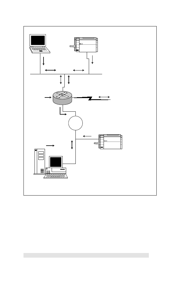
The best way to illustrate access lists is to look at an example for each filter type.
For this example, refer to Figure 7.3. Notice the figure displays the direction of
SAP updates, IPX routing updates, and GNS requests. Further, you can see in
the figure that both routers have a loopback interface (a software interface) run-
ning IPX.
Standard IPX Filters
The first step when applying a standard IPX filter is to reinstall IPX RIP as the
preferred method of routing IPX. To accomplish this, you reissue the ipx router
rip IOS command.
After enabling IPX RIP with the ipx router rip command, we need to create an
access list to stop the network from installing router R2 in router R1’s IPX routing
table. For this task, you simply use a standard access list, as shown in Listing 7.14.
Listing 7.14
IPX Access list example.
interface serial0
ipx input-network filter 800
! Applies access list to
incoming RIP updates
access-list 800 deny 2.ffff.ffff.ffff
! Stops rip updates
learned from IPX network 2
access-list 800 permit -1
!Permits all other networks
The number -1 in the access list indicates to match all networks. Next, you apply
the access list with the ipx input-network-filter 800 interface command. This
command filters incoming IPX RIP updates. You can also filter outgoing net-
work filters by using the ipx output-network-filter <800-899> command. After
executing the preceding commands, router R1 will not have network 2 in its
routing table, as shown in Listing 7.15.
16
○
○
○
○
○
○
○
○
○
○
○
○
○
○
○
○
○
○
○
○
○
○
○
○
○
○
○
○
○
○
○
○
○
○
○
○
○
○
○
○
Chapter 7
Listing 7.15
The show ip route command after filtering network 2 as show
in Listing 7.14.
R1#sh ipx route
4 Total IPX routes. Up to 1 parallel paths and 16 hops allowed.
C 1 (NOVELL-ETHER), Et0
C 3 (UNKNOWN), Lo0
C BAD (HDLC), Se0
R 4 [07/01] via BAD.0000.0c8e.774b, 39s, Se0
Token
Ring
Sends SAP
IPX
RIP
Sends SAP
Tok0
Router
Listens to SAPs
Sends and listens to
IPX Routing updates (IPX RIP)
Send
GNS queries
IPX RIP
SAP
E0
Serial0
Printer
Printer
Client PC
Server
(Also listens for GNS queries
and replies to them)
Figure 7.3
Using access lists and GNS filters to manage IPX traffic.

17
○
○
○
○
○
○
○
○
○
○
○
○
○
○
○
○
○
○
○
○
○
○
○
○
○
○
○
○
○
○
○
○
○
○
○
○
○
○
○
○
Networking and Desktop Protocols
As you can see in Listing 7.15, the network filter stops network 2 and allows all
others, such as the Network 4 loopback interface via the next hop address
BAD.0000.0c8e.774b.
Extended IPX Filters
Extended IPX access list can be applied to both source and destination addresses.
Extended IPX filters range from decimal 900 through 999. Quality examples on
extended IPX access-lists can be found in the IOS documentation CD or at the
following Web site:
http://cco/univercd/cc/td/doc/product/software/ios112/112cg_cr/6rbook/
6ripx.htm#xtocid204644
SAP Filters
Let’s now examine how you can use a SAP filter to stop the printer from being
advertised to IPX network 1. Let’s say that because there is no need to send print
jobs over the WAN, you want to reduce the SAP traffic by placing a filter on
router R2 to stop the printer from being advertised. Placing the filter on R2 will
mean that the SAP does not get broadcast over the WAN. The IOS syntax used
to create a SAP filter is:
ipx output-sap-filter <access list number>
A SAP filter can also be applied on inbound traffic by using the following command:
ipx input-sap-filter <access list number>
Listing 7.16 shows an example of denying a printer from being advertised. List-
ing 7.17 shows the SAP table before a SAP filter is applied.
Listing 7.16
An access list 1000 example of using a SAP filter to stop the
printer from being advertised.
interface serial0
ipx output-sap-filter 1000
access-list 1000 deny -1 7 .
1 Denies all printer advertises
(Type code is 7)
access-list 1000 permit FFFFFFFF 4
! Permits all IPX servers
! (Type code is 4)

18
○
○
○
○
○
○
○
○
○
○
○
○
○
○
○
○
○
○
○
○
○
○
○
○
○
○
○
○
○
○
○
○
○
○
○
○
○
○
○
○
Chapter 7
Listing 7.17
Router R1’s SAP table before applying a SAP filter.
R1#sh ipx server
Codes: S - Static, P - Periodic, E - EIGRP, N - NLSP, H – Holddown
1 Total IPX Servers
Type Name Net Address Port Route Hops Itf
P 7 server 2.0000.2314.0002:0451 7/01 2 Se0
P 4 server1 2.0000.0000.0001:0451 7/01 2 Se0
If you examine router R1’s SAP table, you’ll notice that only the file server is
present and all print services have been removed, as shown in Listing 7.18.
Listing 7.18
Router R1’s SAP table after applying a SAP filter.
R1#sh ipx server
Codes: S - Static, P - Periodic, E - EIGRP, N - NLSP, H – Holddown
1 Total IPX Servers
Type Name Net Address Port Route Hops Itf
P 4 server1 2.0000.0000.0001:0451 7/01 2 Se0
Finally, you can specify what you want a router to do with GNS requests. The
interface command to apply a GNS filter is:
ipx output-gns-filter <1000-1099>
Listing 7.19 displays a SAP filter configuration that will stop a Cisco router
from allowing GNS requests to a network 2 server that has the 0800.4000.1527
node address.
Listing 7.19
An access list 1000 example of denying GNS requests from
being sent to a network 2 server.
interface Ethernet 0
ipx network 1
ipx output-gns-filter 1000
access-list 1000 deny 2.0800.4000.1527
access-list 1000 permit -1
In Listing 7.19, the access list will stop GNS requests from being forwarded to
the network address 2 and IPX node address of 0800.4000.1527. All other re-
quests will be forwarded by the access-list 1000 permit –1 command. Table 7.2
summarizes the main points about filtering IPX traffic on Cisco routers.
You should memorize the three main access lists ranges used to
manage IPX networks. These ranges are list 800 through 899, 900
through 999, and 1000 through1099, respectively.

19
○
○
○
○
○
○
○
○
○
○
○
○
○
○
○
○
○
○
○
○
○
○
○
○
○
○
○
○
○
○
○
○
○
○
○
○
○
○
○
○
Networking and Desktop Protocols
We will now discuss how Cisco routers can support another proprietary protocol
that was used heavily in the 1980s, namely AppleTalk. AppleTalk is still com-
mon in today’s networks.
AppleTalk
AppleTalk is a routable protocol that provides access to servers and printers. You
can use the Routing Table Maintenance Protocol (RTMP) or Cisco’s EIGRP with
AppleTalk. Keep in mind that AppleTalk stations will not recognize EIGRP
updates. Therefore, EIGRP is typically used on WANs, while RTMP is imple-
mented on LANs.
RTMP is a distance-vector protocol. Cisco’s implementation using
EIGRP will not propagate any new AppleTalk networks unless a
network event or change occurs.
AppleTalk is designed to be a plug-and-play technology, which means that its
implementation requires little work for end users. But, while AppleTalk is easy
on end users, it’s more complex and time consuming on the router administrator.
For general reference, Figure 7.4 displays the AppleTalk protocol model com-
pared to the OSI model.
As you can see in Figure 7.4, many functions are performed at various layers of
the model. The lower layers—namely Ethertalk, LocalTalk, TokenTalk, and
FDDITalk—are methods used to access different media. For example, Ethertalk
is used by AppleTalk to send packets over Ethernet. The following summarizes
the main protocols found in an AppleTalk network:
➤ Datagram Delivery Protocol (DDP)—DDP is a connectionless datagram ser-
vice independent of the media type. This means that AppleTalk can support
Ethernet, Token Ring, and FDDI for example.
➤ Name Binding Protocol (NBP)—NBP provides name-to-address association,
similar to DNS in IP networks.
Table 7.2
Managing IPX traffic summary.
Access List Type
Range
Interface Commands
Standard
800 through 899
ipx input-network-filter;
ipx output-network-filter
Extended
900 through 999
ipx input-network-filter;
ipx output-network-filter
SAP/GNS
1000 through 1099
ipx input-sap-filter;
ipx output-gns-filter

20
○
○
○
○
○
○
○
○
○
○
○
○
○
○
○
○
○
○
○
○
○
○
○
○
○
○
○
○
○
○
○
○
○
○
○
○
○
○
○
○
Chapter 7
➤ Zone Information Protocol (ZIP)—ZIP provides a means of maintaining zone
name mappings to network numbers. This reduces broadcasts in large
AppleTalk networks.
When AppleTalk was originally released as an alternative protocol to IP and
IPX, you could only have 127 servers and 127 host devices per segment. The
original AppleTalk version is known as AppleTalk Phase 1. When the AppleTalk
designers soon become aware that AppleTalk Phase 1 was not scalable, they re-
leased AppleTalk Phase 2, which could support up to 253 devices with multiple
networks allowable per segment. Another benefit of Phase 2 is that it does not
limit the number of servers or end devices. Cisco routers support both modes.
Nonextended (AppleTalk Phase 1) networks allow 127 hosts and 127
servers per network, and
extended (AppleTalk Phase 2) networks allow
a total of 253 devices. With extended networks, you can assign a range
of network numbers, called a
cable range in Cisco terminology.
AppleTalk Addresses
Every routable protocol address contains a network address. AppleTalk addresses
are made up of a network and host portion. Further, AppleTalk addresses contain
Application
Presentation
Session
Transport
Network
Data Link
Physical
AppleTalk Model
OSI Model
Zone Information
Protocol
(ZIP)
Printer Access
Protocol
(PAP)
AppleTalk
Filtering Protocol
(AFP)
Routing Table
Maintenance
Protocol (RTMP)
Name Binding
Protocol
(NBP)
Datagram
Delivery
Protocol (DDP)
AppleTalk
Resolution
Protocol (AARP)
Ethertalk, LocalTalk,
TokenTalk, FDDITalk
IEEE802.3, 802.5, FDDI
AppleTalk
Upgrade Routing
Protocol (AURP)
Figure 7.4
The AppleTalk protocol suite.

21
○
○
○
○
○
○
○
○
○
○
○
○
○
○
○
○
○
○
○
○
○
○
○
○
○
○
○
○
○
○
○
○
○
○
○
○
○
○
○
○
Networking and Desktop Protocols
a socket number that is similar to a TCP/IP port. A device may contain more
than one socket. The AppleTalk address format uses the following syntax:
Network (16 bits) Node (8 bits) Socket (8 bits)
Most textbooks describe the AppleTalk address as 24 bits because the socket
address is always unique.
AppleTalk Address Resolution Protocol (AARP) provides layer 3 network
addresses in association with the Physical layer (layer 2) addresses.
AARP’s equivalent in TCP/IP is the Address Resolution Protocol or IP
ARP. The show AppleTalk arp command translates AppleTalk ad-
dresses to physical addresses. Remember, devices still need to access
a medium at layer 2, because AppleTalk nodes require the destination
MAC address to send frames to allow communication over the LAN
protocol, such as Ethernet or Token Ring.
Now, let’s discuss AppleTalk’s native routing protocol RTMP and then follow
with an example.
Routing Table Maintenance Protocol (RTMP)
RTMP broadcasts the entire routing table every 10 seconds. Similar to previous
discussions in this chapter regarding broadcasts and distance-vector protocols,
you should be cautious when using RTMP in large AppleTalk network because
RTMP sends out updates every 10 seconds and is a distance vector protocol.
The RTMP metric is hops. The maximum hops allowable with RTMP is 15.
The
AppleTalk Update-Based Routing Protocol (AURP) is a Transport
layer protocol that allows AppleTalk networks to be transported across
your IP network. AURP enables you to transport AppleTalk packets
across your IP network without the need to enable RTMP across your
WAN. This can help you to avoid RTMP’s high number of routing table
broadcasts.
Configuring AppleTalk with RTMP
To enable AppleTalk routing, the following steps are required:
1. Enable AppleTalk routing.
2. Set interfaces to run AppleTalk by issuing the network range and a zone name.
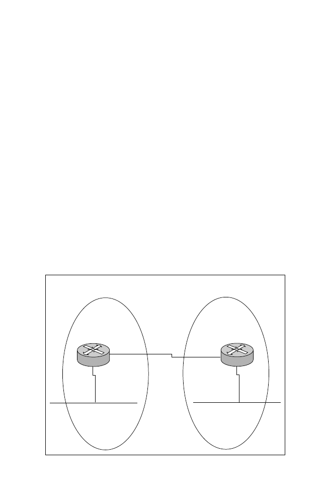
Figure 7.5 illustrates a simple AppleTalk network and the associated ranges on
the LAN and WAN. Let’s configure the two routers for AppleTalk. In this ex-
ample, router R1’s Ethernet segment will have a network range of 1-1, and router

22
○
○
○
○
○
○
○
○
○
○
○
○
○
○
○
○
○
○
○
○
○
○
○
○
○
○
○
○
○
○
○
○
○
○
○
○
○
○
○
○
Chapter 7
2 will have a cable range of 2-2. The WAN link will have a cable range of 3-3.
Listings 7.20 and 7.21 provide the configuration on routers R1 and R2.
Listing 7.20
R1 configuration with AppleTalk enabled.
hostname R1
appletalk routing
! notice the router has its own AppleTalk address of 1.110
interface Ethernet0
appletalk cable-range 1-1 1.110
! The cable range defines the start and end range (1-1) for
! the cable range and the 1.110 defines the node address
! assigned by Cisco router IOS or can be manually entered.
appletalk zone R1
!
interface Serial0
appletalk cable-range 3-3 3.11
appletalk zone WAN
....
Listing 7.21
R2 configuration with AppleTalk enabled.
hostname R2
appletalk routing
interface Ethernet0
appletalk cable-range 2-2 2.230
appletalk zone R2
!
interface Serial0
appletalk cable-range 3-3 3.245
appletalk zone WAN
....
AppleTalk
Cable Range 1-1
Zone R1
E0
AppleTalk
Cable Range 2-2
Zone R2
S0
E0
S0
Cable Range 3-3
Zone WAN
R1
R2
Figure 7.5
AppleTalk example.

23
○
○
○
○
○
○
○
○
○
○
○
○
○
○
○
○
○
○
○
○
○
○
○
○
○
○
○
○
○
○
○
○
○
○
○
○
○
○
○
○
Networking and Desktop Protocols
Listing 7.22 displays R1’s AppleTalk routing table.
Listing 7.22
The show appletalk route command on R1.
R1#sh apple route
Codes: R - RTMP derived, E - EIGRP derived, C-connected, A-AURP
S - static P - proxy
3 routes in internet
The first zone listed for each entry is its default (primary) zone
C Net 1-1 directly connected, Ethernet0, zone R1
R Net 2-2 [1/G] via 3.245, 3 sec, Serial0, zone R2
C Net 3-3 directly connected, Serial0, zone WAN
As you can see in Listing 7.22, there is one remotely learned network
from serial 0, which is the network 2-2. The router discovered the
network via RTMP, and this will be broadcast by R2 every 10 seconds.
This broadcast activity might be fine for a small network, but numerous
broadcasts could use up too much bandwidth on large networks. An
alternative routing protocol to RTMP is AppleTalk EIGRP.
AppleTalk Enhanced Interior Gateway Routing
Protocol (EIGRP)
Cisco’s EIGRP supports AppleTalk networks and provides better routing capa-
bilities across WANs than distance-vector protocols. Unfortunately, you cannot
use AppleTalk EIGRP on end devices, because AppleTalk end stations do not
support EIGRP. Therefore, RTMP must still be used on LANs. Even with that
limitation, there is still a significant amount to be gained by using EIGRP.
AppleTalk EIGRP reduces bandwidth requirements because this is a hybrid pro-
tocol, sending updates only when configuration changes occur.
Let’s look at the tasks required to configure AppleTalk EIGRP routing protocol
and then follow with an example.
Configuring AppleTalk EIGRP
To enable AppleTalk EIGRP, you need to complete the following tasks:
1. Enable AppleTalk EIGRP (appletalk routing eigrp <router-id>).
2. Enable EIGRP on the WAN interface only (appletalk protocol eigrp).
Now, let’s configure a simple AppleTalk network to use RTMP on the local
LANs and EIGRP across the WAN. Listings 7.23 and 7.24 detail the new con-
figurations on R1 and R2 using AppleTalk EIGRP across the serial 0 interface.

24
○
○
○
○
○
○
○
○
○
○
○
○
○
○
○
○
○
○
○
○
○
○
○
○
○
○
○
○
○
○
○
○
○
○
○
○
○
○
○
○
Chapter 7
Listing 7.23
R1 configuration with AppleTalk EIGRP enabled.
Hostname R1
appletalk routing eigrp 1
interface Serial0
appletalk cable-range 3-3 3.11
! The cable range defines the start and end range for the cable
! range and the 3.11 defines the node address assigned to the
! Cisco routers interface.
appletalk zone WAN
appletalk protocol eigrp
no appletalk routing protocol rtmp
Listing 7.24
R2 configuration with AppleTalk EIGRP enabled.
Hostname R2
appletalk routing eigrp 2
interface Serial0
appletalk cable-range 3-3 3.11
appletalk zone WAN
appletalk protocol eigrp
no appletalk routing protocol rtmp
As you can see in the preceding listings, the configuration stops AppleTalk RTMP
(with the command no appletalk routing rtmp on serial 0) updates and enables
the more efficient EIGRP. The router ID must be unique across each router.
Note: It is permissible (maybe even advisable, depending on circumstances) to run
more than one protocol.
Listing 7.25 shows R1’s new routing table, which indicates the remote network
2-2 is reachable via EIGRP (E).
Listing 7.25
The show appletalk command showing R1’s routing table after
enabling EIGRP.
R1#sh apple route
Codes: R - RTMP derived, E - EIGRP derived, C - connected,
A - AURP, S - static, P - proxy
3 routes in internet
C Net 1-1 directly connected, Ethernet0, zone R1
E Net 2-2 [1/G] via 3.245, 554 sec, Serial2, zone R2
C Net 3-3 directly connected, Serial2, zone WAN
The router ID, which is identified by the command appletalk routing
eigrp <router ID>, must be unique to each router. If two routers use
the same router ID, Cisco IOS will not start AppleTalk EIGRP.

25
○
○
○
○
○
○
○
○
○
○
○
○
○
○
○
○
○
○
○
○
○
○
○
○
○
○
○
○
○
○
○
○
○
○
○
○
○
○
○
○
Networking and Desktop Protocols
Managing AppleTalk Traffic with Access Lists
AppleTalk access-lists are used on Cisco routers to manage the services that are
available to end users and to increase performance across a wide area network. To
manage AppleTalk traffic with access lists, you apply the range 600 through 699.
There are four available filtering options:
➤ GetZoneList filter—Filters Zone Information Protocol (ZIP) information lo-
cally between a router and hosts.
➤ ZIP reply filter—Hides zone information between routers only.
➤ Distribute list—Controls RTMP broadcasts between routers.
➤ NBP filter—Controls services and reduces traffic on congested links.
You apply the preceding access lists to the interface with the following interface
commands:
➤ GetZoneList filter—AppleTalk getzonelist-filter <600-699>
➤ ZIP reply filter—AppleTalk zip-reply-filter <600-699>
➤ Distribute list—AppleTalk distribute-list <600-699> {in|out}
➤ NBP filter—Access-group <600-699>
Let’s now discuss the DECnet proprietary protocol developed by the Digital
Corporation. DECnet is a routing protocol that is widely used in Digital net-
working environments.
DECnet
DECnet is a routable proprietary protocol developed by Digital that operates at
layer 3 of the OSI model. DECnet networks are grouped together in areas to
reduce traffic. Similar to OSPF, DECnet nodes elect a designated router (DR) to
maintain a broadcast network, such as Ethernet. End devices use the DECnet
DR to send packets to unknown destinations.
DECnet is commonly referred to as Phase IV, or the latest release version is
called Phase V or Open System Interconnect (OSI) Phase V.
To set the priority of a router to make it eligible to become a DR, you
use the DECnet router-priority <0-127> command. The highest
priority “wins.” If there is a tie, the device with the highest node
address becomes the DR. The default priority is 64.
DECnet is a routing protocol that uses cost as the metric. The administrator
assigns the cost, although local entries have a cost value of 0. On a Cisco router,

26
○
○
○
○
○
○
○
○
○
○
○
○
○
○
○
○
○
○
○
○
○
○
○
○
○
○
○
○
○
○
○
○
○
○
○
○
○
○
○
○
Chapter 7
the cost is assigned by using the DECnet cost <value> IOS command. The key
features of DECnet are:
➤ The nodes are placed in areas.
➤ Hello packets are used to discover new devices.
➤ Broadcasts are suppressed.
➤ Routing updates occur every 40 seconds.
➤ The metric used is cost.
As with other routable protocols, a DECnet address is made up of a network and
host portion. With DECnet, the network portion describes the host’s area, and
the host portion identifies the end device. Routers in one area are called level 1
routers, while routers in two or more areas are called level 1/2 routers. Level 1/2
routers can communicate with both level 1 and level 2 routers. Level 1 routers
talk to end stations and level 1 routers within their area. Level 2 routers talk to
level 1 routers in their area and level 2 routers in different areas. End devices and
both level 1 and level 2 routers use the hello protocol to discover each other.
Note: Level 1 routers perform routing within an area. Level 2 routers perform level
1 functions as well as level 2 functions, which include routing between areas.
Let’s examine the DECnet address format. A DECnet address uses the follow-
ing syntax:
area (6 bits) node (10 bits)
The assignment of only 6 bits to the area portion means that the range of pos-
sible area assignments goes from 1 through 63.
In earlier versions of DECnet, a way to accommodate Ethernet was developed
by using the modified MAC address calculate form the DECnet node address.
Therefore, DECnet does not require a node-to-MAC address translation, be-
cause the modified MAC address overrides the burned-in address (BIA). The
node address is calculated as follows:
1. Start with an address AA-00-04-00 for all DECnet nodes.
2. Assign a DECnet address, and convert it to binary.
3. Swap the first 8 bits with the second 8 bits.
4. Convert to hexadecimal, and append to the originating address (AA-00-04-00).
To further illustrate, let’s determine the local MAC address that will be used by a
DECnet Phase IV device. For this example, let’s say that you have a device with
the DECnet address of 7.10.
27
○
○
○
○
○
○
○
○
○
○
○
○
○
○
○
○
○
○
○
○
○
○
○
○
○
○
○
○
○
○
○
○
○
○
○
○
○
○
○
○
Networking and Desktop Protocols
The first 8 bytes are AA-00-04-00. The last two bytes are calculated by convert-
ing 7.10 to binary, which is 00000111.00001010. Then, you swap the two bytes
in binary to become 00001010.00001111, which is the equivalent of 0A1C in
hexadecimal. Next, you combine the first 8 bytes with the hexadecimal number.
Therefore, the MAC address used by the DECnet node is AA-00-04-00-0A-
1C. This is not the DECnet address, which is of the form x.y (16 bits and 7.10 in
the previous example), but the address that will be used at layer 2. The MAC
address is used to send to remote stations and because the layer 2 MAC address
is derived from the network address (in the example shown previously, the DECnet
address 7.10 is calculated in the NIC software as the layer 2 address AA-00-04-
00-0A-1C). Hence, there is no requirement for an ARP protocol as the MAC
address can be derived from the DECnet address.
Configuring DECnet on Cisco Routers
The following steps are required to enable DECnet routing on a Cisco router:
1. Enable DECnet routing, and assign a DECnet address.
2. Specify a level 1 or level 2 router.
3. Assign costs to interfaces that will run DECnet.
To further clarify, let’s configure the network shown in Figure 7.6 for DECnet
routing. In this example, router R1 will be placed in area 1 with a node address of
E0
S0
E0
S0
R1 (1-1)
R2 (2-2)
DECnet
Area 1
DECnet
Area 2
Figure 7.6
Simple DECnet network.

28
○
○
○
○
○
○
○
○
○
○
○
○
○
○
○
○
○
○
○
○
○
○
○
○
○
○
○
○
○
○
○
○
○
○
○
○
○
○
○
○
Chapter 7
1.1, and router R2 will be placed in area 2 with the node address of 2.2. Listings
7.26 and 7.27 display the configurations required to accomplish DECnet con-
nectivity between routers R1 and R2.
Listing 7.26
R1 configured with DECnet connectivity.
hostname R1
DECnet routing 1.1
! Starts DECnet routing,DECnet address 1.1
DECnet node-type area
! Specifies level 2 router
interface Ethernet0
DECnet cost 10
interface Serial0
DECnet cost 10
....
Listing 7.27
R2 configured with DECnet connectivity.
hostname R2
DECnet routing 2.1
DECnet node-type area
interface Ethernet0
DECnet cost 10
interface Serial0
DECnet cost 10
....
Listing 7.28 shows the routing table for router R1 after enabling DECnet.
Listing 7.28
The show DECnet route command on router R1.
R1>sh DECnet route
Area Cost Hops Next Hop to Node Expires Prio
*1 0 0 (Local) -> 1.1
*2 10 1 Serial0 -> 2.1 36 64 A+
Node Cost Hops Next Hop to Node Expires Prio
*(Area) 0 0 (Local) -> 1.1
*1.1 0 0 (Local) -> 1.1
To enable a router to be a level 1 DECnet router, you must use the
DECnet routing DECnet route iv-prime <DECnet address>
command.
As you can see in Listing 7.28, the remote DECnet node 2.1 (router R2) is
reachable via serial 0 (next hop address). The Cost indicates the assigned cost to
reach a DECnet network or interface enabled for DECnet on a Cisco router.
The Hops field indicates the number of hops necessary to reach the remote network.

29
○
○
○
○
○
○
○
○
○
○
○
○
○
○
○
○
○
○
○
○
○
○
○
○
○
○
○
○
○
○
○
○
○
○
○
○
○
○
○
○
Networking and Desktop Protocols
The Expires field indicates how long (in seconds) before the entry will expire if a
route is not received. The Prio field designates the priority. Following the priority
value, the A+ indicates that the DECnet node is part of another area. (Level 2
adjacency, level 1 adjacency is displayed as V in a DECnet routing table on a
Cisco router).
DECnet chooses the path with the lowest cost when attempting to
reach a remote destination.
Table 7.3 summarizes some useful DECnet commands.
DECnet Phase V
DECnet Phase V is the newest version of DECnet, and the addressing scheme
follows the scheme described in Chapter 6. DECnet Phase V addresses use the
following syntax:
Domain Area System ID SELGOSIP format
Phase IV and Phase V networks can coexist. Phase V enables more nodes to exist
(it supports 10
28
nodes). Further, the routing protocol has been enhanced to in-
clude the state of adjacent links to provide groundwork for future routing schemes.
The key features of DECnet Phase V are:
➤ Supports more nodes than DECnet Phase IV
➤ Supports naming services
➤ Supports electronic messaging (email)
Managing DECnet Traffic with Access Lists
To manage DECnet traffic, you can place filters on end nodes based on a source
or destination DECnet address. Filters on routing updates can also be performed.
Table 7.3
Summary of DECnet commands.
Command
Description
show DECnet route
Displays DECnet routing table
show DECnet neighbors
Displays DECnet adjacencies
show DECnet interface
Displays interface configuration and status
show DECnet traffic
Displays DECnet traffic statistics
debug DECnet routing
Displays routing table transactions and updates
debug DECnet adjacencies
Displays packets sent to neighboring routers

30
○
○
○
○
○
○
○
○
○
○
○
○
○
○
○
○
○
○
○
○
○
○
○
○
○
○
○
○
○
○
○
○
○
○
○
○
○
○
○
○
Chapter 7
Access lists ranging from 300 through 399 are used to filter DECnet traffic. To
use an access list, you first define an access list and then apply it to the appropri-
ate interface. To illustrate, let’s consider a simple access list that will permit all
DECnet nodes ranging from areas 1 and 2, as shown in Listing 7.29.
Listing 7.29
An access list that permits all DECnet nodes ranging from areas
1 and 2.
interface E0
DECnet access-group 300
access-list 300 permit 1.0 0.1023 0.0 63.1023
access-list 300 permit 2.0 0.1023 63.1023
The access list configured in Listing 7.29 permits nodes from areas 1 and 2. The
mask used in this case is 0.1023, which means that a 0 must match the area 1 and
a mask of 1023 means we ignore all host addresses. In Listing 7.29, 63 and 1023
are used as “don’t care bits” in a DECnet access-list. Remember, DECnet ad-
dressing consists of 10 bits for the node address and 6 bits for the area. 63 in
binary is 111111, and 1023 in binary is 1111111111. A 1 is used in an access list
to indicate bits you don’t care to match. By default, a DECnet access list like all
Cisco access-lists denies all networks not explicitly permitted.
The equivalent of using a mask of 63.1023 in DECnet is the keyword
any for an IP access list.
Windows NT and NetBIOS
This section briefly covers Windows NT and two networking protocols used by
Windows PCs, namely NetBEUI and NetBIOS. We’ll begin by briefly covering
Windows NT.
Windows NT allows clients and servers to be grouped into domains or workgroups.
A domain is typically a large group of devices under a common administration. A
workgroup usually describes a smaller group of Windows devices or any logical
collection of computers. A domain is managed by a primary domain controller
(PDC), which is a Windows-based server that stores and controls security and user
account information for an entire domain. Each domain must have at least one
PDC. A workgroup is defined as a logical connection. A backup domain control-
ler (BDC) maintains a copy of the database in the event the PDC is unavailable.
Let’s cover another protocol developed by IBM, namely NetBEUI and NetBIOS.
NetBEUI was first developed by IBM in the mid-1980s to provide an interface
for applications that were currently using NetBIOS (Network Basic Input/Output
31
○
○
○
○
○
○
○
○
○
○
○
○
○
○
○
○
○
○
○
○
○
○
○
○
○
○
○
○
○
○
○
○
○
○
○
○
○
○
○
○
Networking and Desktop Protocols
System). NetBEUI is not routable and must be bridged in cases where networks
are not locally reachable. NetBEUI was also designed for earlier versions of Win-
dows, namely Windows 3.1 and MS-DOS based clients.
NetBIOS is a Session layer protocol that is used to allow communication be-
tween domains or workgroups. NetBIOS provides the following functions:
➤ Authentication
➤ Connection management
➤ Error control
➤ File sharing
➤ Flow control
➤ Full-duplex transmissions
➤ Name resolution
➤ Print sharing
➤ Session management
Figure 7.7 displays the NetBIOS model.
Application
Presentation
Session
Transport
Network
Data Link
Physical
NetBIOS NetBEUI Model
OSI Model
NetBIOS Interface
NetBIOS Applications, such as Server
MessageBlock (SMB), which is
used for file transfer, for example
TCP
IPX
IP
NetBEUI
802.3
Ethernet
802.5
Token Ring
Figure 7.7
The NetBIOS model.

32
○
○
○
○
○
○
○
○
○
○
○
○
○
○
○
○
○
○
○
○
○
○
○
○
○
○
○
○
○
○
○
○
○
○
○
○
○
○
○
○
Chapter 7
As you can see in Figure 7.7, NetBIOS can operate over three protocols—
NetBEUI (non-routable), IPX (routable), and TCP/IP (routable).
NetBIOS over IPX is called
NWLink, and NetBIOS over TCP/IP is
called
NetBT.
We’ll now move on and discuss how Windows devices can find network resources
by browsing and using Windows name resolution.
Browsing and Windows Names Resolution
Windows NT’s browsing service, called Network Neighborhood, provides end us-
ers with a list of all devices available in their network. Before a user’s PC can
browse the network or Network Neighborhood, the Windows-based PC must
register its name periodically by sending a broadcast to the master browser. The
master browser contains a list of all devices available on the network. This ser-
vice, called browsing, is supported by three methods—NetBEUI, NWLink, and
NetBT. In addition to accessing the Network Neighborhood services, Windows
devices require name resolution so that network names can be translated to pro-
tocol addresses, either IP or IPX.
Networking administrators have four options for name resolution, which are simi-
lar to the Domain Name System (DNS) provided by TCP/IP. These four name
resolution options for Windows NT network administrators are:
➤ Broadcasts—This method enables end stations to broadcast their names to a
designated master browser (typically a Windows NT server). The master
browser collects the names of available devices and maintains a list. The list is
then sent to all devices that request it. This allows communication between
servers and clients.
➤ LMhosts file—This simple method enables local PCs to maintain a static list
of all computers available in the network. The file typically contains the name
and protocol addresses of all servers available in the domain. For large net-
works, the file might become too large and unusable, so a service called Win-
dows Internet Naming Services (WINS) was developed (as described in the
next item in this list).
➤ Windows Internet Naming Services (WINS)—WINS was developed so Win-
dows network administrators could avoid coping with a large amount of broad-
casts or statically defined lists. WINS allows client PCs to dynamically register
and request name resolution by a specific server running the WINS services.
Instead of sending broadcasts, the client sends unicasts. WINS typically runs

33
○
○
○
○
○
○
○
○
○
○
○
○
○
○
○
○
○
○
○
○
○
○
○
○
○
○
○
○
○
○
○
○
○
○
○
○
○
○
○
○
Networking and Desktop Protocols
on a Windows NT server and has an IP address. Clients are statically or
dynamically configured to use the server’s IP address.
➤ Dynamic Host Configuration Protocol (DHCP)—In large networks (which con-
tain thousands of PCs), a static IP address configuration can become time
consuming. Therefore, DHCP was developed to dynamically allocate IP ad-
dresses as well as many other parameters, such as subnet masks, gateways, and
WINS server addresses. When you use DHCP, a Windows client sends out a
broadcast for an IP address, and the DHCP server (a Windows NT server or
compatible device) provides all the necessary TCP/IP information. The cli-
ent then registers its names with the WINS server so browsing can take place.
Note: You can control a Windows environment by using access lists. Depending on
the protocol you are using, you can apply IP access lists or IPX access lists to control
traffic. You can also control DHCP broadcasts by using the ip helper-address <ip
address of DHCP server> command. By default, a router will drop all layer 3
broadcasts, and the preceding command will enable you to change the broadcast to a
unicast. The ip helper-address command is used to get DHCP requests from one
layer 3 segment that doesn’t have a DHCP server to a Layer 3 segment that does
contain a DHCP server.
Scaling Issues in Windows NT
In larger Windows environments, you can have many domains. Windows NT
allows information sharing between domains with the use of trusted domains. A
trusted domain is used to grant or deny access to clients without having to man-
age each user individually. Each domain can exchange information and form a
relationship called a trust relationship. Based on these trust relationships, end us-
ers from each domain can be allowed or denied access. Creating trust relation-
ships allows secure data to flow between different domains and ensure adequate
security for data files and application files in any Windows based network.
Windows NT supports several domain models, including:
➤ Single domain—A model used in small networks.
➤ Master domain—A master domain is trusted by all remote domains, but the
master does not trust the remote domains.
➤ Multiple master domains—A model used in very large networks where the
master domain is trusted by other master domains, which in turn trust smaller
domains.

34
○
○
○
○
○
○
○
○
○
○
○
○
○
○
○
○
○
○
○
○
○
○
○
○
○
○
○
○
○
○
○
○
○
○
○
○
○
○
○
○
Chapter 7
Practice Questions
Question 1
Where in the OSI model does IPX routing occur?
❍ a. Layer 1
❍ b. Layer 2
❍ c. Layer 3
❍ d. Layer 4
❍ e. Layer 7
The correct answer is c. IPX routing occurs at the Network layer (layer 3) like all
routing protocols. Answers a, b, d, and e are incorrect, because layer 1 is the
Physical layer, layer 2 is the Data Link layer, layer 4 is the Transport layer, and
layer 7 is the Application layer.
Question 2
What protocol is used by IPX at the Transport layer in the IPX model?
❍ a. EIGRP IPX
❍ b. IPX
❍ c. UPX
❍ d. SPX
The correct answer is d. SPX is the protocol used at the Transport layer in the
IPX model. Answers a and b are incorrect, because EIGRP IPX and IPX are
layer 3 protocols. Answer c is incorrect, because UPX is an invalid protocol.

35
○
○
○
○
○
○
○
○
○
○
○
○
○
○
○
○
○
○
○
○
○
○
○
○
○
○
○
○
○
○
○
○
○
○
○
○
○
○
○
○
Networking and Desktop Protocols
Question 3
What access list range is used to filter GNS requests?
❍ a. 100 through 199
❍ b. 1 through 99
❍ c. 800 through 899
❍ d. 1000 through 1099
❍ e. 900 through 999
The correct answer is d. IPX access lists ranging from 1000 through 1099 are
used to filter get nearest server (GNS) requests. GNS requests are sent by IPX
end stations to request a connection to an IPX server. Answer a is incorrect,
because 100 through 199 is an IP extended access list range. Answer b is incor-
rect, because the range 1 through 99 is used by a standard IP access list. Answers
c and e are incorrect, because the ranges 800 through 899 and 900 through 999
are used for filtering IPX networks.
Question 4
Which of the following is a valid IPX address?
❍ a. 00000001
❍ b. 1.4000.2399.70cd
❍ c. 4000.2399.70cd
❍ d. ffff.ffff.ffff.ffff
The correct answer is b. An IPX address is made up of 32 bits describing the
network portion and 48 bits describing the node portion, such as 1.4000.2399.70cd
in answer b. Answer a is incorrect, because, while 00000001 is a valid network
address, it doesn’t include the node address. Answer c is incorrect, because only
the node portion of the address is valid. Answer d is incorrect, because
ffff.ffff.ffff.ffff is a broadcast address and cannot be used as a local IPX address.

36
○
○
○
○
○
○
○
○
○
○
○
○
○
○
○
○
○
○
○
○
○
○
○
○
○
○
○
○
○
○
○
○
○
○
○
○
○
○
○
○
Chapter 7
Question 5
What metric is used by IPX RIP? [Choose the two best answers]
❑ a. Bandwidth
❑ b. MTU
❑ c. Ticks
❑ d. Hops
❑ e. None of the above
The correct answers are c and d. IPX uses both ticks (a measure of delay) and hop
count as a metric. Answers a and b are incorrect, because bandwidth and MTUs
are not taken into account by IPX RIP. Answer e is incorrect, because the correct
options are provided.
Question 6
When the ipx routing command is issued on a Cisco router, what IPX rout-
ing protocol is used by default?
❍ a. IP RIP
❍ b. IPX RIP
❍ c. IPX EIGRP
❍ d. NLSP
The correct answer is b. By default, when IPX routing is started on a Cisco router,
IPX RIP will be the routing protocol. Answer a is incorrect, because IP RIP is
used by IP, not IPX. Answer c is incorrect, because you must configure a Cisco
router to use IPX EIGRP; IPX EIGRP is not the default. Answer d is incorrect,
because you must configure a Cisco router to use NLSP; NLSP is not the default.
Question 7
How many bits are used to describe an IPX node address?
❍ a. 80
❍ b. 32
❍ c. 48
❍ d. 16

37
○
○
○
○
○
○
○
○
○
○
○
○
○
○
○
○
○
○
○
○
○
○
○
○
○
○
○
○
○
○
○
○
○
○
○
○
○
○
○
○
Networking and Desktop Protocols
The correct answer is c. An IPX address is made up of a node address and net-
work address. An IPX node address is taken from the MAC address, which is 48
bits in length. The network address is 32. The question specifically asks for the
node address, making answer c correct. Answers a, b, and d are incorrect, because
node addresses are 48 bits.
Question 8
How many bits are used to describe an AppleTalk address?
❍ a. 16
❍ b. 24
❍ c. 32
❍ d. 48
The correct answer is c. An AppleTalk address is made up of a network portion
(16 bits), a host portion (8 bits), and a socket portion (8 bits), which totals 32 bits.
Answers a, b, and d are incorrect, because AppleTalk addresses are 32 bits.
Question 9
What is AppleTalk’s native routing protocol?
❍ a. RIP
❍ b. RTA
❍ c. RTMP
❍ d. EIGRP
The correct answer is c. AppleTalk’s native routing protocol is the Routing Table
Maintenance Protocol (RTMP). Answer a is incorrect, because RIP is used by IP
and IPX. Answer b is incorrect, because RTA is an invalid routing protocol. An-
swer d is incorrect, because EIGRP is Cisco’s proprietary protocol that enables
networks to route AppleTalk across a WAN.

38
○
○
○
○
○
○
○
○
○
○
○
○
○
○
○
○
○
○
○
○
○
○
○
○
○
○
○
○
○
○
○
○
○
○
○
○
○
○
○
○
Chapter 7
Question 10
What is RTMP’s maximum hop count?
❍ a. 10
❍ b. 15
❍ c. 16
❍ d. 255
The correct answer is b. RTMP’s maximum hop count for routing AppleTalk is
15. This is because only 4 bits are reserved for hop counts in the routing update
packet. Answers a, c, and d are incorrect, because 15 hops is the correct answer.
Question 11
What access list range is used to manage AppleTalk traffic?
❍ a. 1 through 99
❍ b. 100 through 199
❍ c. 600 through 699
❍ d. 100 through 1000
The correct answer is c. AppleTalk access lists range from 600 through 699. An-
swers a and b are incorrect, because, while the ranges aren’t used to manage
AppleTalk traffic, they are used to filter IP traffic. Answer d is incorrect, because
it is an invalid access list range.
Question 12
What IOS command is used to set the DECnet priority to 200 on an Ethernet
interface?
❍ a. Decnet priority 200
❍ b. Decnet router-priority 200
❍ c. Decnet 200
❍ d. The priority value must be between 0-127

39
○
○
○
○
○
○
○
○
○
○
○
○
○
○
○
○
○
○
○
○
○
○
○
○
○
○
○
○
○
○
○
○
○
○
○
○
○
○
○
○
Networking and Desktop Protocols
The correct answer is d. The DECnet priority is a value from 0 through 127. The
IOS syntax to set the priority is decnet router-priority <0-127>. Answers a, b,
and c are incorrect, because they display commands with incorrect syntax.
Question 13
How many bits are used to describe a DECnet address?
❍ a. 32
❍ b. 24
❍ c. 12
❍ d. 16
The correct answer is d. A DECnet address is made up of 16 bits—the first 6 bits
are used to describe an area, and the last 10 bits are used to describe the node
address. Answers a, b, and c are incorrect, because 16 bits is the correct answer.
Question 14
Which of the following services provided by a Windows NT Server will allo-
cate parameters such as an IP address and a default gateway?
❍ a. WINS
❍ b. DHCP
❍ c. LMhosts
❍ d. Master browser
The correct answer is b. DHCP provides an IP address and a default gateway
address to devices requesting it. Answer a is incorrect, because WINS is used to
provide name resolution. Answer c is incorrect, because LMhosts uses a file to
provide static name resolution. Answer d is incorrect, because the master browser
contains a list of available services in a Windows environment.

40
○
○
○
○
○
○
○
○
○
○
○
○
○
○
○
○
○
○
○
○
○
○
○
○
○
○
○
○
○
○
○
○
○
○
○
○
○
○
○
○
Chapter 7
Question 15
Which of the following protocols is not routable in a Windows environment?
❍ a. IP
❍ b. IPX
❍ c. NetBEUI
The correct answer is c. NetBEUI is a layer 2 protocol that must be bridged
because it has no network layer addressing. Answers a and b are incorrect, be-
cause IP and IPX are routable protocols.

41
○
○
○
○
○
○
○
○
○
○
○
○
○
○
○
○
○
○
○
○
○
○
○
○
○
○
○
○
○
○
○
○
○
○
○
○
○
○
○
○
Networking and Desktop Protocols
Need To Know More?
Advanced Cisco Router Configuration (ACRC). Macmillan Publishing
Company, Indianapolis, IN, 1998. ISBN 1-57870-074-4. Chapter 4
describes how you can manage IPX traffic, and Appendix B describes
filtering AppleTalk traffic.
Chappell, Laura: Introduction to Cisco Router Configuration Course
(ICRC). Macmillan Publishing Company, Indianapolis, IN, 1998. 1-
57870-076-0. Chapters 11 and 12 provide an excellent introduction
into IPX and AppleTalk configuring and monitoring capabilities on
Cisco IOS routers. Appendix B provides an excellent description of
DECnet.
The Cisco Documentation, CD-ROM has detailed explanations about
configuring and monitoring IPX, AppleTalk, and DECnet.
www.openvms.digital.com/openvms/brochures/DECnetplus/
index.html provides excellent documentation on DECnet capabilities
for all types of platforms.

Wyszukiwarka
Podobne podstrony:
433 8C03 6D5LOD4KUALBGAZYU2BPHU Nieznany
433 8C06 IUPZAHYZLTJ5FVC5ASSTC7 Nieznany
433 8C08 CCONPVVGMRFKY3H2SV6MLO Nieznany
433 8C09 XQQ4BS6NLYEERPUAIKQR75 Nieznany (2)
433 8C02 JQVRRLWPBK322K7TFJA45L Nieznany
433 8C05 CWJ323BUNESSWSM7ARIJUO Nieznany
433 8C10 3FPMCIVQISRE4NQU7HR5KM Nieznany (2)
433 8C04 NMVY43YFSQAYQTRGRSPPKV Nieznany
KPG 433 12 id 249386 Nieznany
4 kanaly Remote Control UHF 433 Nieznany (2)
Gor±czka o nieznanej etiologii
02 VIC 10 Days Cumulative A D O Nieznany (2)
Abolicja podatkowa id 50334 Nieznany (2)
45 sekundowa prezentacja w 4 ro Nieznany (2)
4 LIDER MENEDZER id 37733 Nieznany (2)
Mechanika Plynow Lab, Sitka Pro Nieznany
więcej podobnych podstron