
1
○
○
○
○
○
○
○
○
○
○
○
○
○
○
○
○
○
○
○
○
○
○
○
○
○
○
○
○
○
○
○
○
○
○
○
○
○
○
○
○
○
○
○
○
○
○
○
○
5
TCP/IP Networking
Terms you’ll need to understand:
✓ Subnet mask
✓ Subnetting
✓ Classless Interdomain Routing (CIDR)
✓ Transmission Control Protocol/Internet Protocol (TCP/IP)
✓ Address Resolution Protocol (ARP)
✓ Reverse Address Resolution Protocol (RARP)
✓ Hot Standby Routing Protocol (HSRP)
✓ Telnet
✓ Ping
✓ File Transfer Protocol (FTP)
Techniques you’ll need to master:
✓ Describing IP address classes
✓ Identifying TCP/IP functions
✓ Identifying the use of Network Address Translation (NAT)
✓ Explaining TCP/IP application services

2
○
○
○
○
○
○
○
○
○
○
○
○
○
○
○
○
○
○
○
○
○
○
○
○
○
○
○
○
○
○
○
○
○
○
○
○
○
○
○
○
Chapter 5
This chapter delves into many of the commonly confused topics within the world
of internetworking. Mastery of these topics is essential for CCIE candidates;
these technologies will serve you well in your daily activities. We begin with the
most common protocol, TCP/IP, and we’ll use it as the base for our more ad-
vanced discussions throughout this chapter and the remainder of the book.
The following CCIE blueprint objectives as laid out by the Cisco Systems CCIE
program are covered in this chapter:
➤ Addressing—Classless Interdomain Routing (CIDR), subnetting, Address
Resolution Protocol (ARP), Network Address Translation (NAT), Hot
Standby Router Protocol (HSRP)
➤ Services—Domain Name System (DNS), Bootstrap Protocol (BOOTP),
Dynamic Host Configuration Protocol (DHCP), Internet Control Message
Protocol (ICMP)
➤ Applications—Telnet, File Transfer Protocol (FTP), Trivial File Transfer
Protocol (TFTP)
➤ Access Lists—Standard access lists and extended access lists, including where
and how to place and design them
As with other chapters in this book, we have provided additional information in
this chapter for both completeness and in preparation for additional subjects as
the CCIE program expands. This will allow you to use this book as a reference
source throughout the CCIE certification process and beyond.
TCP/IP Overview
Transmission Control Protocol/Internet Protocol (TCP/IP) is by far the most
popular networking protocol in use today. The Internet links many different hard-
ware types, and TCP/IP enables the various hardware types to communicate
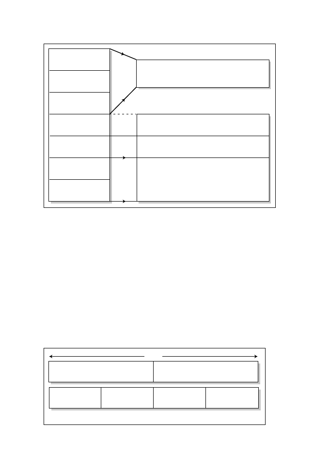
effectively with each other. Figure 5.1 shows the TCP/IP protocol suite and how
it maps to the seven-layer OSI model.
When using TCP/IP in the OSI model, the Transport layer (TCP or UDP)
provides connection orientation (TCP) or connectionless services (UDP), and
the Network layer (IP) provides best-effort delivery (connectionless). The next
section describes what makes up an IP address and the associated addressing
schemes available. Later in this chapter, we’ll take a closer look at TCP’s functions.
The Internet Protocol (IP) was described by Jon Postel in RFC 791 in
September 1981. The following URL provides you with some of the
most common RFC’s are available: www.cisco.com/warp/customer/
459/index.shtml.
3
○
○
○
○
○
○
○
○
○
○
○
○
○
○
○
○
○
○
○
○
○
○
○
○
○
○
○
○
○
○
○
○
○
○
○
○
○
○
○
○
TCP/IP Networking
IP Addressing Review
The network layer addressing used by IP is a field 32 bits in length and repre-
sented in a dotted decimal format, such as 10.99.34.50. IP addresses have three
defined portions: a network portion, a host portion, and a subnet mask. A subnet
mask (also a 32-bit field) is used to identify and distinguish between the network
and host portions, as discussed later in this chapter. Figure 5.2 demonstrates a
typical network address, using a Class A IP address.
In Figure 5.2, the number 10 represents a network portion, and the numbers
99.34.50 represent the host portion. Together, these two portions form the IP
address, which is 32 bits in length.
Application
Presentation
Session
Transport
Network
Data Link
Physical
Telnet File Transfer
BOOTP, DHCP,
Protocol (FTP)
TFTP, NTP
Ethernet
T/Ring
FDDI
(802.3)
(802.5)
(ANSI X3T9.5)
ATM
TCP provides connection-oriented delivery
UDP provides connectionless delivery
OSPF, RIP, IGEP/EIGRP, BGP
ICMP
Figure 5.1
OSI-TCP/IP model.
Network
Host
10
99
34
50
8 bits
8 bits
8 bits
8 bits
32 bits
Figure 5.2
A typical IP address.

4
○
○
○
○
○
○
○
○
○
○
○
○
○
○
○
○
○
○
○
○
○
○
○
○
○
○
○
○
○
○
○
○
○
○
○
○
○
○
○
○
Chapter 5
The original RFC classified IP addressing into five main classes. Table 5.1 lists
the RFC’s IP address classes. Using the table, you can see that the IP address
shown in Figure 5.2 is a Class A address.
The address range 127.0.0.0 is reserved for loopback devices. For ex-
ample when you read the Cisco documentation CD-ROM on your PC,
the address used is 127.0.0.1 to indicate the local CD-ROM drive. Class
D addresses are reserved for Multicast groups. The address
255.255.255.255 is reserved for broadcasts.
By applying a default mask, as shown in Table 5.1, to an IP address, the IP model
is known as the classful model. IP routing protocols that use Table 5.1’s defini-
tions are referred to as classful routing protocols (for example, RIP v1). This is
contrasted with routing protocols that use a mask other than the default. These
types of routing protocols are known as classless routing protocols (for example,
OSPF). Class D addressing is reserved for multicast groups. For example, the
Cisco IP routing protocol Enhanced Interior Gateway Routing Protocol (EIGRP)
sends multicast hello packets to the multicast address 224.0.0.10. Class E ad-
dressing is reserved for future use.
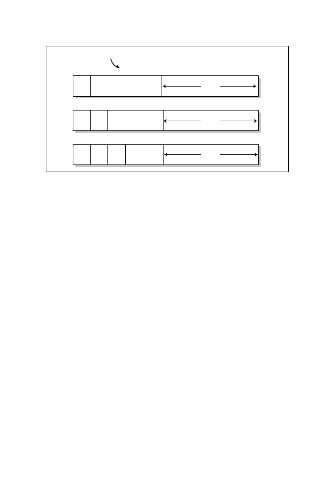
A simple way to observe an IP address’s class is to look at the first couple of bits
in the IP address’s first octet. The value contained within the first few bits will
tell you what class of IP address you are working with:
➤ 0—Class A network
➤ 10—Class B networks
➤ 110—Class C networks
➤ 1110—Class D networks
➤ 11110—Class E networks
You can clearly see how the bit pattern indicates the class of the IP address, as
shown in Figure 5.3.
Table 5.1
IP address classes.
Address Class
Range
Default Subnet Mask
Class A
1 through 126
255.0.0.0
Class B
128 through 191
255.255.0.0
Class C
192 through 223
255.255.255.0
Class D
224 through 239
255.255.255.240
Class E
240 through 255
Reserved
5
○
○
○
○
○
○
○
○
○
○
○
○
○
○
○
○
○
○
○
○
○
○
○
○
○
○
○
○
○
○
○
○
○
○
○
○
○
○
○
○
TCP/IP Networking
Note: A Cisco router will apply the longest match rule when deciding where an an IP
packet will be sent. Consider the case in which a router can have two or more
different next hop addresses for the same network. The router will choose the next hop
that has the longest mask that matches the destination network. This is called the
longest match rule.
Due to the rapid growth of hosts on the Internet or intranets (not public net-
works), it was soon evident to the Internet community that IP addressing would
eventually be depleted. Therefore, to allow for the continued expansion of the
Internet, subnetting was implemented to allow IP administrators to maximize
the use of an IP address space.
Subnetting
Subnetting allows the network or IP address administrator to maximize the use
of an IP address space within the network. A subnet mask borrows bits from an
IP address’s host portion and uses the bits to define new networks. If subnetting
is implemented, IP addresses have three sections:
➤ Network
➤ Subnet (new)
➤ Host Address
Note: All IP addresses have a mask associated with them, either implied (default) or
defined. There are three address representations: dotted decimal, bitcount, and
hexadecimal.
The subnet or network defines the arbitrary segmentation performed by the network
administrator. The subnet allows the creation of a hierarchical routing network.
Network
Host
Class A
Class B
Class C
0
Network
0
Network
0
1
1
1
Host
1
1
1
1
1
1
21
14
7
Bits required
24 bits
16 bits
8 bits
1-126
128-191
192-223
Ranges
Host
Figure 5.3
Bit patterns for Class A, Class B, and Class C addressing.

6
○
○
○
○
○
○
○
○
○
○
○
○
○
○
○
○
○
○
○
○
○
○
○
○
○
○
○
○
○
○
○
○
○
○
○
○
○
○
○
○
Chapter 5
A subnet mask is a 32-bit decimal number that is used to identify a network and
its host addresses. Subnet masks can be the classful kind, as shown earlier in
Table 5.1.
Class A, B, and C network addressing schemes are not much use in today’s com-
plex Internetworks unless you extend the mask or use variable length subnetting
to avoid wasting IP address space. The phrase variable length subnet mask (VLSM)
refers to the fact one network can be configured with different subnet masks. For
example, a network could be configured to have one mask that allows only two
hosts and another mask that can be extended to allow 512 hosts. VLSM ensures
that IP addressing is not wasted. Think of a serial line that contains two routers.
Why assign a Class C address for two nodes? Instead, you could assign an ad-
dress (subnet) that contains only two hosts; the mask 255.255.255.252 can be
used to accomplish this.
To determine the number of hosts or subnets available on a network, you need to
examine the IP addresses in binary. To determine the number of hosts or subnets
you can assign to a network, you apply the formula 2
n
-2, where n equals the
number of borrowed bits. Why are two subnets subtracted? Because one address
is reserved to identify the subnet and the other is used to send broadcasts (bits
that are set to all 0s or all 1s are used for broadcasts). Determining how many
hosts or subnets you can assign to a network is best explained with examples.
Let’s assume the subnet mask 255.255.255.240 has been applied to your net-
work. How many subnets are available when assigning the subnet address of
131.108.1.0?
Looking at the subnet mask, you can interpret the 240 as 11110000 in binary.
Hence, 4 bits have been borrowed from the host portion of the IP address to
form a subnet. Therefore, the subnet mask formula would be 2
4
-2, which equates
to 14 subnets (2*2*2*2=16-2=14). Why do we take away 2 subnets? The reason is
that they are used to represent the subnet and the broadcast address. Bits that are
set to all 0s are the network (wire address) and all 1s are used for broadcasts. This
can be shown in the following:
131.108.1.0 255.255.255.240
In this subnet and subnet mask, note that:
➤ Network address
131.108.1.0
➤ First usable host address
131.108.1.1
➤ Last usable host address
131.108.1.14
➤ Directed Broadcast address
131.108.1.15
➤ Broadcast address
255.255.255.255

7
○
○
○
○
○
○
○
○
○
○
○
○
○
○
○
○
○
○
○
○
○
○
○
○
○
○
○
○
○
○
○
○
○
○
○
○
○
○
○
○
TCP/IP Networking
Similarly, consider the mask 255.255.255.192. How many end nodes could re-
side on the network? Note that 192 in binary is 11000000. Hence, two bits have
been borrowed, so the end nodes can use the last six bits. The formula would be
2
6
-2, which equates to 62 hosts.
Note: When using a 26-bit subnet mask, you need to use the ip subnet command to
access all of the subnets that the mask allows!
It is vital that you have a good understanding of how an IP address’
network and host portion is calculated. You should be able to calculate
the number of hosts on a network using any IP addressing scheme.
For additional review, let’s look at a couple more examples of how to calculate the
host and subnet portion of any given class of address.
Given the host address of 131.108.1.93/24, what is the subnet and broadcast address?
You need to know what a network address such as 131.108.1.0/24
means. In this example, the address is the equivalent of the network
131.108.1.0 with a subnet mask of 255.255.255.0, or 24 bits of
subnetting.
The notation 131.108.1.93/24 means that the subnet mask uses 24 bits, or the
equivalent of a subnet mask represented as 255.255.255.0 in dotted format. There-
fore, 131.108.1.93/24 is the same as 131.108.1.93 255.255.255.0. In binary,
131.108.1.93 is:
10000011.01101100.00000001.01011101
And the mask, 255.255.255.0 in binary is:
11111111.11111111.11111111.00000000
Performing a logical AND operation on the host address and subnet mask will
provide you with the subnet mask, which has been derived as 255.255.255.0, or a
Class C address. To determine the subnet, you must perform a logical AND
function on the host. Logical AND means that 1 and 1 equates to 1 only. The
remaining options are 0 AND 0 is 0, 0 AND 1 is 0. The logical AND operation
provides the following:
10000011.01101100.00000001.01011101 IP ADDRESS
11111111.11111111.11111111.00000000 Subnet Mask
EQUALS NETWORK
10000011.01101100.0000001.0000000

8
○
○
○
○
○
○
○
○
○
○
○
○
○
○
○
○
○
○
○
○
○
○
○
○
○
○
○
○
○
○
○
○
○
○
○
○
○
○
○
○
Chapter 5
10000011.01101100.0000001.0000000 is a 131.108.1.0 subnet address. To de-
termine the broadcast address, you need the decimal equivalent of all one bits
(11111111), which is 255; hence, the broadcast address of a 131.108.1.0 subnet is
131.108.1.255.
Finally, let’s look at a Class A host address of 10.99.34.50. Using a Class C mask,
what is the network portion and how many hosts can reside on this network?
The logical AND function is performed once more. A Class C mask is
255.255.255.0 when represented in decimal format. Therefore, 10.99.34.50 and
255.255.255.0 in binary is
00001010.01100011.00100010.00110010
11111111.11111111.11111111.00000000
A logical AND between the address and mask yields:
00001010.01100011.00100010.00000000
00001010.01100011.00100010.00000000 indicates a subnet of 10.99.34.0. The
number of hosts available on a Class C mask is 2
8
-2, or 254 hosts, because 2
addresses are used to identify the subnet and the directed broadcast address. A
directed broadcast address is sent to all hosts on the subnet only. (10.99.34.0 is
the subnet and 10.99.34.255 is a directed broadcast address for all users on the
local subnet.)
Table 5.2 provides a useful guide that can help you to prepare for the exam. Table 5.2
displays the decimal value and binary value of a subnet number followed by the
number of available subnets. The number of hosts that can reside on each subnet
follows.
Note: Try some subnet examples on your own and then compare them to a subnet
calculator freely available on the Internet. Cisco’s Web site (www.cisco.com/
techtools/ip_addr.html) has a subnet calculator.
Table 5.2
Common subnets.
Decimal
Subnets
Hosts
252 (11111100)
64 subnets
2 hosts
248 (11111000)
32 subnets
6 hosts
240 (11110000)
16 subnets
14 hosts
224 (11100000)
8 subnets
30 hosts
192 (11000000)
4 subnets
62 hosts
128 (10000000)
2 subnets
126 hosts

9
○
○
○
○
○
○
○
○
○
○
○
○
○
○
○
○
○
○
○
○
○
○
○
○
○
○
○
○
○
○
○
○
○
○
○
○
○
○
○
○
TCP/IP Networking
Now that we’ve covered the IP addressing and the formats that are used to repre-
sent IP addresses, let’s move on to a more advanced IP routing concept—Class-
less Interdomain Routing (CIDR).
Classless Interdomain Routing (CIDR)
In the past few years, the expansion of the Internet has been phenomenal. Cur-
rently, the Internet uses more than 70,000 routes. From 1994 through 1996 the
routing table was increased from around 20,000 entries to more than 42,000.
How can network administrators reduce the large routing table size? Each rout-
ing entry requires memory and a table lookup by the router each time a packet is
required to reach a destination. Reducing memory requirements and the time it
takes to send a packet to the destination provides faster response times for pack-
ets to travel around the Internet.
Classless Interdomain Routing (CIDR) helps to reduce the number of routing
table entries and memory requirements. CIDR helps to conserve resources, be-
cause it removes the limitation of using the default mask (which wastes IP ad-
dress space) and leaves the addressing up the IP designer. CIDR is used by routers
to group networks together in order to reduce routing table size and memory
requirements. CIDR is typically represented with the network number/bits used in
the mask, such as 131.108.1.0/24, or the equivalent of 131.108.1.0 255.255.255.0.
Now that we’ve covered CIDR and the purpose of CIDR, let’s move on to how
devices such as PCs map layer 2 addresses to layer 3 addresses using Address
Resolution Protocol (ARP) and Reverse Resolution Protocol (RARP).
ARP and RARP
Address Resolution Protocol (ARP) and Reverse Resolution Protocol (RARP)
carry out important functions in the TCP/IP model, which allows devices to
communicate at layer 2 of the OSI model. Remember, all frames are sent to a valid
MAC address. So, before one IP host can communicate with another, the source
device must have an identified layer 2 address to traverse the physical medium or
use broadcast frames to locate resources on any particular physical media.
ARP is used when a source device needs to know the destination’s layer 2 MAC
address to allow communication between two devices. ARP is a layer 2 frame
sent as a broadcast frame with a known IP address requesting the destination’s
MAC address. For example, you might Telnet to a local router with a known IP
address, such as 131.108.1.99. Your PC does not have a layer 2 address or MAC
address to send the frame to, so ARP obtains the MAC address. For example,
ARP is used between a Client PC and a Cisco router for the Telnet application
protocol. In contrast, RARP is used when a source device knows a destination’s
10
○
○
○
○
○
○
○
○
○
○
○
○
○
○
○
○
○
○
○
○
○
○
○
○
○
○
○
○
○
○
○
○
○
○
○
○
○
○
○
○
Chapter 5
MAC address but the IP address is unknown. RARP obtains the unknown IP
address. Typically, RARP is used with diskless workstations where the worksta-
tions send out requests for IP addresses with a known local MAC address.
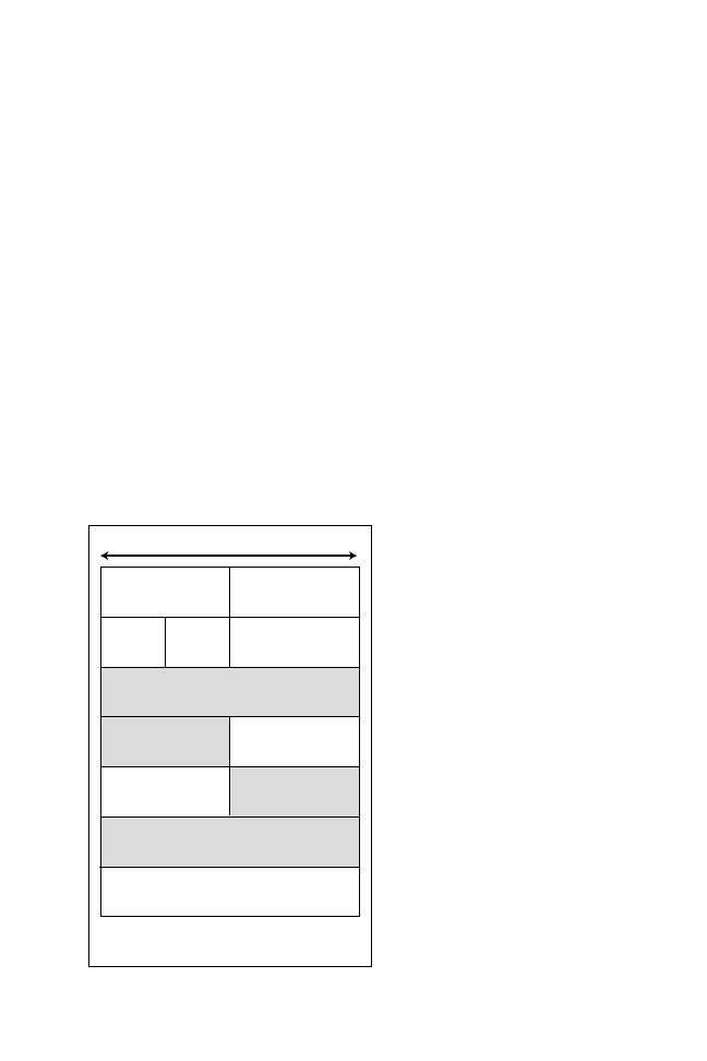
Figure 5.4 shows the ARP/RARP frame format. The function of each field in an
ARP and RARP frame is described as follows:
➤ Hardware Type—Specifies the hardware in use. For example, this value is set
to 1 for Ethernet or 6 for IEEE 802 networks.
➤ Protocol—Indicates the protocols in use. For example, 0800 is used to indicate IP.
➤ Length of Hardware Address—Indicates the length of layer 2 addresses, 48 bits.
➤ Length of Protocol Address—Defines length of protocol addresses. For example,
for IP this field is set to 4 bytes (32 bits).
➤ Operation Code—Defines whether the frame is an ARP or RARP. 1 is an
ARP request, 2 is an ARP reply, 3 is a RARP request, and 4 is a RARP reply.
➤ Sender Hardware Address—Identifies the sender’s layer 2 MAC address (48 bits).
➤ Sender Protocol Address—Identifies the sender’s IP address (32 bits).
Target Hardware Address
Target Protocol Address
Hardware
Type
32 bits
Protocol
Operation Code
Length of
Protocol
Address
Length of
Hardware
Address
Sender Hardware Address
Sender Hardware
Address
Sender Protocol
Address
Sender Protocol
Address
Target Hardware
Address
Note: Hardware addresses are 48 bits (32 + 16)
and protocol address are 32 bits in length.
Figure 5.4
ARP/RARP frame format.

11
○
○
○
○
○
○
○
○
○
○
○
○
○
○
○
○
○
○
○
○
○
○
○
○
○
○
○
○
○
○
○
○
○
○
○
○
○
○
○
○
TCP/IP Networking
➤ Target Hardware Address—Specifies a destination’s address. In an ARP re-
quest, this field is set to a broadcast of FF-FF-FF-FF-FF-FF (48 bits).
➤ Target Protocol Address—Specifies a destination’s layer 3 address (32 bits).
The ARP and RARP protocol will provide IP-aware devices with valuable informa-
tion needed to successfully send data across a network, regardless of hardware types.
You should ask yourself what MAC address will a local device use to
send an IP packet to a remote station, which may have many routers in
between. Most commonly, a local device will use the local gateway or
the local router’s MAC address.
To display the IP ARP table on a router, you issue the IOS show ip arp com-
mand, as shown in Listing 5.1.
Listing 5.1
The show ip arp command.
R1>sh ip arp
Protocol Address Age (min)Hardware Addr Type Interface
Internet 10.1.1.1 - 0000.0c3b.ed6d ARPA Ethernet0
Internet 10.1.1.5 - 0000.0c3b.ed6d ARPA Ethernet0
Internet 137.10.16.3 1 0000.0c07.ac00 ARPA Ethernet0
Internet 137.10.16.2 - 0000.0c3b.ed6d ARPA Ethernet0
Internet 137.10.17.1 - 0000.30dc.b736 SNAP TokenRing0
Internet 137.10.16.4 12 0060.2f53.5cff ARPA Ethernet0
Listing 5.1 provides the IP address and the associated MAC address used to
reach a device. To clear the ARP cache on a Cisco router, you use the clear arp
command.
Note: If your router is configured for other routable protocols, such as AppleTalk, the
show arp command will also display AppleTalk ARP entries. To display only IP
ARP entries, use the show ip arp command.
Remember, there is also another type of ARP used in Frame Relay networks—
Proxy ARP. Proxy ARP maps the DLCI to the remote IP address, essentially a
layer 2 to layer 3 mapping in Frame Relay. We will now look at how a network
can use Network Address Translation (NAT) to connect to the Internet, even
though the network does not have a registered address.
Network Address Translation (NAT)
To reduce the impact of network address depletion due to the rapid growth of the
Internet, many large IP networks needed the ability to retain their current ad-
dressing scheme yet be able access the Internet. This can be accomplished with
Network Address Translation (NAT) defined in RFC 1631.

12
○
○
○
○
○
○
○
○
○
○
○
○
○
○
○
○
○
○
○
○
○
○
○
○
○
○
○
○
○
○
○
○
○
○
○
○
○
○
○
○
Chapter 5
The implementation of NAT by the Cisco IOS supports most of the appli-
cations we have discussed so far, including Domain Name System and
File Transfer Protocol. The common applications supported on Cisco
routers running NAT include the following:
➤ Routing table updates (OSPF, RIP, and so on)
➤ HTTP, DNS zone transfers, TFTP, BOOTP, telnet, SNMP, finger, NTP,
NFS, rlogin, rsh, rcp
➤ ICMP, FTP (including PORT and PASV commands), NetBIOS over TCP/IP.
The following URL provides a full list of supported applications:
www.cisco.com/cpropart/sync-src/ccstcp/cc/cisco/mkt/ios/nat/prodlit/
792_pp.htm#xtocid11070
NAT is a standard defined in RFC 1631. Cisco devices started supporting NAT
in IOS versions 11.2 and higher. NAT grants the ability to retain a network’s
original IP addressing scheme while translating that scheme to valid Internet IP
addresses. Thus the layer 3 address is changed when the packet is sent out to the
Internet and vice versa.
NAT Terminology
To clarify this discussion and to fully prepare for the exam, you should review
some of the terminology used in a NAT environment. You need to understand a
number of terms when using NAT, most notably:
➤ Inside Local Address—An IP address assigned to a host on the internal network
and is not being advertised to the Internet. This address is generally assigned
by a local administrator. This address is not a legitimate Internet address.
➤ Inside Global Address—A registered IP address as assigned by InterNIC.
➤ Outside Local Address—The IP address of an outside host of the network that
is being translated.
➤ Outside Global Address—The IP address assigned to a host on the outside of
the network that is being translated.
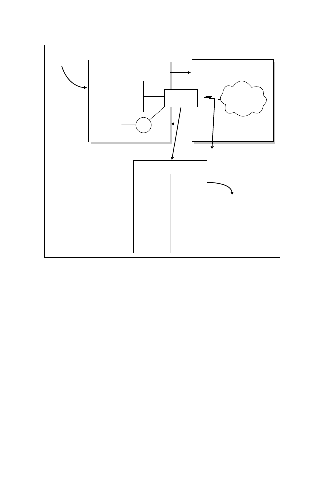
NAT Operation on Cisco Routers
When a packet leaves an inside network, NAT translates the inside address to a
unique InterNIC address for use on the outside network, as shown in Figure 5.5.
The router in Figure 5.5 will be configured for an address translation and will
maintain a NAT table. When the packet returns from the outside network, the
NAT router will again perform an address translation from the valid InterNIC
address to a local inside address.
13
○
○
○
○
○
○
○
○
○
○
○
○
○
○
○
○
○
○
○
○
○
○
○
○
○
○
○
○
○
○
○
○
○
○
○
○
○
○
○
○
TCP/IP Networking
Let’s look at the steps required to configure NAT on a Cisco router. The basic
configuration tasks are as follows:
1. Determine the network addresses to be translated.
2. Configure inside network with the IOS ip nat inside command.
3. Configure the outside network with the IOS ip nat outside command.
4. Define a pool of addresses that will be translated with the following
IOS command:
ip nat pool <pool-name> <start ip address> <end ip address>
<mask>
5. Define the addresses that will be allowed to access the Internet with the
following IOS command:
ip nat inside source list <access list number> pool <pool name>
Inside local
IP addresses
Inside Network
Outside Network
Cisco Router
R1
10.99.34.5
PC
10.99.35.5
PC
Ethernet
TR1
Internet
Hosts
S0
E0
Inside global IP address
assigned by InterNIC,
131.108.1.1/24
NAT Table
Inside
Address
10.99.34.5
10.99.35.5
|
|
|
|
Outside
Address
192.108.1.1
192.108.1.2
|
|
|
|
InterNIC has assigned
you the address
192.108.1.0 to
192.108.1-254/24
(This pool of NAT
addresses is CCIE.)
Figure 5.5
NAT overview.

14
○
○
○
○
○
○
○
○
○
○
○
○
○
○
○
○
○
○
○
○
○
○
○
○
○
○
○
○
○
○
○
○
○
○
○
○
○
○
○
○
Chapter 5
Now, for a more specific illustration, let’s configure NAT on Router R1 in Figure 5.5,
the NAT pool name is going to be CCIE (you can use any name). Let’s assume
that InterNIC has assigned you the Class C address of 192.108.1.0/24. Your
service provider has also supplied you the unique address 131.108.1.1/24 to use
on your serial connection. Listing 5.2 provides a sample NAT configuration for
this setup. The listing assumes that your setup has an IP routing protocol that
advertises the 131.108.1.0/24 and 192.108.1.0/24 IP networks.
Listing 5.2
Sample NAT configuration.
hostname R1
ip nat pool CCIE 192.108.1.1 192.108.1.254 netmask 255.255.255.0
ip nat inside source 1 pool CCIE
interface e0
ip address 10.99.34.1 255.255.255.0
ip nat inside
interface tokenring0
ip address 10.99.35.1 255.255.255.0
ip nat inside
interface serial 0
ip address 131.108.1.1 255.255.255.0
ip address 192.108.1.1 255.255.255.0 secondary
ip nat outside
access-list 1 permit 10.99.34.0 0.0.0.255
access-list 1 permit 10.99.35.0 0.0.0.255
Listing 5.2’s configuration will translate the inside addresses 10.99.34.0/24 and
10.99.35.0/24 into the globally unique addresses in the range 192.108.1.1—
192.108.1.254/24.
Monitoring NAT
To monitor the operation of NAT, you can use the following commands:
show ip nat translation [verbose]
show ip nat statistics
The show ip nat translation command displays the current active transaction.
The show ip nat statistics command displays NAT statistics, such as how many
translations are currently taking place.
NAT can also support many other advanced features, such as TCP load distribu-
tion. See the “Need to Know More Section” at the end of this chapter for addi-
tional sources of information.
15
○
○
○
○
○
○
○
○
○
○
○
○
○
○
○
○
○
○
○
○
○
○
○
○
○
○
○
○
○
○
○
○
○
○
○
○
○
○
○
○
TCP/IP Networking
Note: TCP load distribution is typically used in large IP networks that have server
farms. A server farm contains two or more servers that are typically critical to a high
end users. You might want to distribute network TCP traffic across many servers but
only use one IP address. TCP load distribution will ensure all servers are equally
loaded. TCP load distribution is sometimes referred to as Port Address Translation
(PAT). PAT basically uses the same IP address, but different port addresses.
Hot Standby Router Protocol (HSRP)
HSRP is a protocol that allows networks to provide a virtual default gateway.
Through HSRP you create a virtual default gateway address that is shared by
multiple routers.
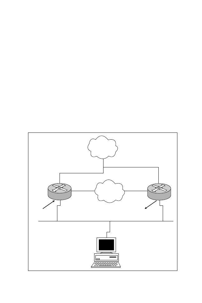
To illustrate how HSRP can provide default gateway support, refer to Figure 5.6.
In Figure 5.6, you can see a network with two local routers configured with an
Ethernet interface address of 131.108.1.1/24 for Router R1 and 131.108.1.2/24
for Router R2. Notice that both routers share a common Ethernet network. All
IP Backbone
R1
R2
S0
S0
131.108.1.1/24
131.108.1.2/24
Default gateway 131.108.1.100
(for all hosts on this network)
131.108.1.100
HSRP
131.108.1.0/24
IO
IO
Figure 5.6
Example without HSRP.
16
○
○
○
○
○
○
○
○
○
○
○
○
○
○
○
○
○
○
○
○
○
○
○
○
○
○
○
○
○
○
○
○
○
○
○
○
○
○
○
○
Chapter 5
devices in Figure 5.6 have been configured with a default gateway pointing to
Router R1. If Router R1 goes down or the Ethernet interface becomes faulty, all
the devices must be manually reconfigured to use the second default gateway
(Router R2 Ethernet address). HSRP enables the network administrator to elect
one of the two routers to act as the default gateway. If the elected router goes
down, the second router assumes the IP default gateway. The IOS command
under the Ethernet interface, standby track <interface of WAN> will allow the
router to monitor the WAN link. If the WAN link continuously fails past a thresh-
old, the HSRP default router will decrease its priority to allow a more reliable
WAN connection to provide a gateway. For example in Figure 5.6, if the link on
R1 to the WAN fails past a threshold then R2 will assume the HSRP address to
provide a faster connection to the IP backbone network.
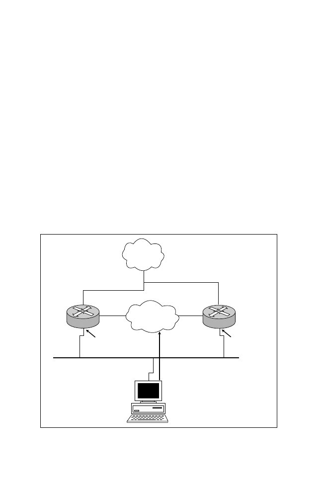
As shown in Figure 5.6, having redundant routers is helpful, but hosts can get
confused because they are typically only allowed one default gateway. When us-
ing HSRP, as shown in Figure 5.7, both routers retain their unique Ethernet
addresses. However, HSRP allows them to share a virtual address. This virtual
address is assigned to each host as its default gateway. In the event of a router
failure, the other will assume control of the virtual address.
IP Backbone
R1
R2
S0
S0
131.108.1.1/24
131.108.1.2/24
Default gateway 131.108.1.100
Default gateway MAC Address is
00-C0-0C-C1-AC-01
E0 MAC Address
(physical)
00-D0-97-D9-8000
E0 MAC Address (physical)
00-D0-97-D9-7000
Virtual MAC Address
00-00-0C-07-AC-01
Figure 5.7
Example Using HSRP.

17
○
○
○
○
○
○
○
○
○
○
○
○
○
○
○
○
○
○
○
○
○
○
○
○
○
○
○
○
○
○
○
○
○
○
○
○
○
○
○
○
TCP/IP Networking
Configuring HSRP
You can configure certain HSRP parameters to elect a default gateway router and
monitor routers’ WAN links. To illustrate, let’s configure HSRP on Routers R1
and R2 shown in Figure 5.6. Let’s make Router R1 the default gateway, because
the link on Router R2 is occasionally prone to WAN problems. All PCs on the
network are configured to use the default IP gateway 131.108.1.100/24. Listing 5.3
displays the configuration for Routers R1 and R2.
Listing 5.3
HSRP configuration on R1 and R2.
Hostname R1
interface Ethernet0
ip address 131.108.1.1 255.255.255.0
standby priority 120
!Highest priority wins
standby preempt
standby ip 131.108.1.100
!HSRP address used by local devices
standby track Serial0
! Monitor serial 0 for failures
Hostname R2
ip address 131.108.1.2 255.255.255.0
standby priority 110
standby preempt
standby ip 131.108.1.100
standby track Serial0
In Listing 5.3, Router R1 will be the active default gateway, because it has the
higher priority. If Router R1 fails, Router R2 will assume the virtual IP address of
131.108.1.100.
Monitoring HSRP
To monitor HSRP settings, you can use the show standby command. The show
standby command displays a router’s state and which router is active. Listing 5.4
displays the output from the show standby command.
Listing 5.4
The show standby command.
Ethernet0 - Group 0
Local state is Active, priority 120, may preempt
Hellotime 3 holdtime 10
Next hello sent in 00:00:01.108
Hot standby IP address is 131.108.1.100 configured
Active router is local
Standby router is 131.108.1.2 expires in 00:00:08
Tracking interface states for 1 interface, 1 up:
Up Serial0

18
○
○
○
○
○
○
○
○
○
○
○
○
○
○
○
○
○
○
○
○
○
○
○
○
○
○
○
○
○
○
○
○
○
○
○
○
○
○
○
○
Chapter 5
Listing 5.4 is taken from Router R1, and it displays R1’s local state as active. This
means that Router R1 has assumed the role of the default gateway. Other valid
router states are speak (negotiating who will become the default gateway, highest
priority will win) and standby (backup router).
Theoretically, end users will not see any significant network outage if one of the
routers or interfaces becomes unreachable. The ARP protocol will resolve the
new Virtual MAC address and hosts will start to use R2 as the default gateway.
HSRP is supported over Token Ring and ATM LANE (IOS 11.2+)
networks.
Now that we’ve reviewed some of the functions of the IP layers and how you can
provide a resilient network, let’s look at a typical Transport Control Program
session running over the IP layer, including how a typical TCP session is started
and terminated.
Transport Control Protocol (TCP)
TCP runs over IP and provides guaranteed delivery of packets to their destina-
tion. Let’s examine how this protocol behaves in a typical network connection
(Chapter 2 covers the TCP segment format in detail). With interactive TCP
data flow, the flags are vital.
Using TCP Flags
The flag fields in a TCP segment contain important details regarding how net-
work devices, such as how routers or other devices, should handle the TCP seg-
ment or UDP datagram. Table 5.3 presents the 6 bits in a TCP segment that are
commonly referred to as flags.
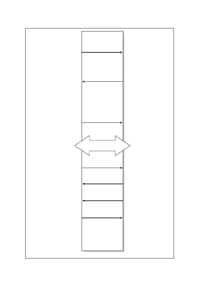
Now, let’s examine a typical Telnet connection startup, data transfer, and session
closure between a PC and a Cisco router. Figure 5.8 shows a typical TCP session.
Reviewing a typical TCP session will help you to see how TCP flags are set and
changed as a session is started and shut down.
The steps in a TCP Telnet session are:
1. A PC sends a request with the SYN bit sent to 1. The destination port
number will be 23 (Telnet). The PC will also place an initial sequence num-
ber (such as, 14810532) in the segment; this is a random number generated
by the PC.

19
○
○
○
○
○
○
○
○
○
○
○
○
○
○
○
○
○
○
○
○
○
○
○
○
○
○
○
○
○
○
○
○
○
○
○
○
○
○
○
○
TCP/IP Networking
2. The router responds with its own sequence number (such as, 3646349618)
and acknowledges (ACK) the segment sent by the PC.
3. The PC sends a segment that acknowledges (ACK) the routers reply.
Note: The first 3 steps are commonly known as the TCP three-way handshake.
4. Data is transferred.
5. The PC completes the data transfer and closes the Telnet session by sending
a TCP segment with the FIN flag set to 1.
6. The router acknowledges (ACK) the request with an acknowledgement.
7. At this stage, the session is still open and the router could send data (this is
known as TCP half close), but it usually doesn’t send data. Instead, the router
usually sends a segment with the FIN bit set to 1.
8. The PC acknowledges the request routers FIN request, and the Telnet ses-
sion is closed.
You need to know the TCP process and how packets are sequenced
and acknowledged. TCP acknowledgements specify the next expected
segment from a sender. A TCP session requires three segments to start
and four to shut down.
You can see in Figure 5.8 that whenever a device requests a TCP session, the
SYN bit is set to 1. If you are concerned about unauthorized users from the
Internet, then you should not allow sessions to initiate (originate) from the Internet.
In other words, do not only allow Telnet sessions (or any other for that matter)
that have the SYN set to 1 from outside of your network.
Table 5.3
Flags in a TCP segment.
Flag
Function
URG (U)
(Urgent) Informs the other station that urgent data is being carried.
The receiver will decide what do with the data.
ACK (A)
(Acknowledge) Specifies a number to use to synchronize segment
flows between devices.
PSH (P)
(Push) Informs the end station to send data to the Application layer
immediately.
RST (R)
(Reset) Resets an existing connection.
SYN (S)
(Synchronize) Initiates a connection, commonly known as
established.
FIN (F)
(Finished) Indicates that the sender is finished sending data and
terminates the session.
20
○
○
○
○
○
○
○
○
○
○
○
○
○
○
○
○
○
○
○
○
○
○
○
○
○
○
○
○
○
○
○
○
○
○
○
○
○
○
○
○
Chapter 5
Step 1
PC requests a Telnet session.
Flags U A P R S F
0 0 0 0 1 0
Destination Port is 23 or Telnet.
Inital sequence is 14810532.
Ack set to 0.
Step 3
Flags U A P R S F
0 1 0 0 0 0
Sequence is 14810533.
Ack 364639619.
Step 5
Flags U A P R S F
0 1 1 0 0 1
Step 8
PC acknowledges request.
Step 6
PC acknowledges request.
Step 7
Router also tears down
connection.
Flags U A P R S F
0 1 1 0 0 1
Step 2
Router responds with its
own sequence number, and
acknowledges the segment
by increasing the PC
sequence number by one.
Flags U A P R S F
0 1 0 0 0 0
Source port is 23.
Ack is 14810533.
Its own sequence is
3646349618.
Connection
Request (SYN)
Connection
Reply (ACK and SYN)
PC acknowledges
Router (ACK)
Data Flow
PC tears down
session (FIN)
(ACK)
(ACK)
PC
Router
(FIN)
Note: It takes 3 TCP
segments to open
a telnet session
and 4 TCP segments
to close it.
Step 4
Figure 5.8
A typical TCP session.

21
○
○
○
○
○
○
○
○
○
○
○
○
○
○
○
○
○
○
○
○
○
○
○
○
○
○
○
○
○
○
○
○
○
○
○
○
○
○
○
○
TCP/IP Networking
Other TCP Functions
TCP is a vast topic and it is impossible to cover it in one chapter (entire books
have been written about TCP). Table 5.4 summarizes some of the main func-
tions of TCP. For further study, see the “Need to Know More” section for some
TCP resources.
Let’s now discuss some of the application services provided by TCP/IP, includ-
ing how TCP/IP users can access remote devices, how diskless workstation can
boot over an IP network, and how name resolution can be handled.
TCP/IP Services
The TCP/IP protocol provides a number of services that allow users to connect
to local or remote hosts. Specifically, these services include:
➤ Domain Name System (DNS)
➤ Bootstrap Protocol (BOOTP)
➤ Dynamic Host Configuration Protocol (DHCP)
➤ Internet Control Message Protocol (ICMP)
The following sections cover each of these services along with the IOS com-
mands used to implement them on Cisco routers.
Table 5.4
Other TCP functions.
Function Name
Description
TCP Half Close
Allows one station to receive data, even though it has
completed data transfer.
Simultaneous Open
Specifies the state when two stations simultaneous try to
connect to each other. TCP detects this event and shuts down
one of the sessions.
Simultaneous Close
Specifies the event when two stations close at the same time.
TCP handles this situation.
Slow Start
Monitors the rate at which segments are sent and acknowl-
edged to make sure no segments are lost in intermediate parts
of the network. The window size is gradually increased; hence,
the name
slow start.
Nagle Algorithm
States that only one TCP connection can have only one
outstanding packet to be acknowledged at any time. The Nagle
algorithm is turned off by default on a Cisco router. To turn it on,
apply the service Nagle command.

22
○
○
○
○
○
○
○
○
○
○
○
○
○
○
○
○
○
○
○
○
○
○
○
○
○
○
○
○
○
○
○
○
○
○
○
○
○
○
○
○
Chapter 5
DNS
In a large IP environment, network users need an easier way to connect to hosts
without having to remember 32 bit IP addresses—that’s where the Domain Name
System (DNS) comes into play. DNS provides a service that allows users to use a
host’s “name” in place of an IP address in order to connect to hosts. When DNS
services are running the host’s name is used to request its IP address from a DNS
server (a host running the DNS service) and do the translation for the user trans-
parently. In other words the user never sees this request and host to IP address
translation. The client simply connects to a host name, and a DNS server does
the translation.
To illustrate, let’s look at the following Cisco router command that provides a
host lookup for users connected via the console or virtual ports (note a router will
not provide DNS server responses to client devices such as PC’s or Unix hosts):
ip host Router2 131.108.1.2
Using the preceding command, the router will automatically translate the name
Router2 to the IP address of 131.108.1.2 when requested. The host name is used
in place of the IP address. This is the basic function of DNS. DNS runs over
UDP and uses port number 53.
Bootstrap Protocol (BOOTP)
BOOTP provides the ability to for diskless PCs to download their operating
system across the network. The use of BOOTP is becoming increasingly uncom-
mon in today’s modern network, however this aging technology is still required
to be part of a CCIE’s knowledge.
By default, Cisco routers do not forward broadcasts. BOOTP requests are sent as
layer 2 broadcasts; hence, by default, BOOTP requests will be dropped by a Cisco
router. BOOTP can be supported across routers using the IOS interface con-
figuration command ip helper-address <address of bootp server>. BOOTP runs
over UDP using port 67 on the server and 68 on a client. When the helper ad-
dress is configured, Cisco routers forward data on the following ports:
➤ TFTP requests port 69
➤ DNS queries port 53
➤ Time requests port 37
➤ NetBIOS name service port 137
➤ NetBIOS datagram service port 137

23
○
○
○
○
○
○
○
○
○
○
○
○
○
○
○
○
○
○
○
○
○
○
○
○
○
○
○
○
○
○
○
○
○
○
○
○
○
○
○
○
TCP/IP Networking
➤ BOOTP 68 (to server)
➤ TACAS port 49
To forward a specific port, you use the syntax ip forward-protocol {udp [port]}.
Dynamic Host Configuration Protocol (DHCP)
Dynamic Host Configuration Protocol (DHCP) enables TCP/IP clients to re-
quest certain parameters, such as their IP address, mask, and default gateway
from a server offering the DHCP service. DHCP reduces the common scalability
issues of configuring every single host on a network with an IP address. DHCP
is an extension of the BOOTP protocol.
To use DHCP, a TCP/IP client sends out a broadcast to request its IP address,
and the DHCP server (a device running DHCP, such as a Windows NT server)
replies with the requested parameters, such as the default gateway and subnet
mask. If a DHCP server does not exist on the local network, you can configure a
Cisco router to relay these broadcasts. By default, a broadcast will not be for-
warded by a router. However, the IOS ip helper-address <server ip address> com-
mand will relay the broadcast to a specified unicast address, the DHCP server (as
discussed in the preceding section).
Internet Control Message Protocol (ICMP)
The Internet Control Message Protocol (ICMP) provides a number of useful
services that are supported by the TCP/IP protocol, including ping requests and
replies. Ping requests and replies enable an administrator to test connectivity
with a remote device.
ICMP also provides feedback control in the form of messages to end devices.
ICMP is described by RFC 792. Be aware that ICMP runs over IP, which means
that there is no guarantee of delivery (because IP is a connectionless protocol).
Listing 5.5 provides a sample ping command in which an administrator wishes
to see if a remote device is reachable by sending the remote device a ping request
from a Cisco router. By default a Cisco router will send out a series of five ICMP
requests whenever the ping command is issued.
Listing 5.5
The ping command.
R2>ping 131.108.1.1
Type escape sequence to abort.
Sending 5, 100-byte ICMP Echos to 131.108.1.1,
!!!!!
Success rate is 100 percent (5/5),
R2>

24
○
○
○
○
○
○
○
○
○
○
○
○
○
○
○
○
○
○
○
○
○
○
○
○
○
○
○
○
○
○
○
○
○
○
○
○
○
○
○
○
Chapter 5
The exclamation point (!) indicates a successful reply. The ping command can
also advise you that the end device is not reachable via a special code character, as
depicted in Table 5.5.
There are three other common applications that use TCP/IP, namely Telnet, File
Transfer Protocol (FTP), and Trivial File Transfer Protocol (TFTP). These ser-
vices use well-known TCP ports, as follows:
➤ Telnet—TCP port 23
➤ File Transfer Protocol—TCP ports 20 and 21
Trivial File Transfer Protocol or (TFTP) runs over IP/UDP and uses port num-
ber 69.
Telnet
Telnet runs over TCP and provides the ability to connect to and manage remote
devices. When you connect from one router to another, you are using the Telnet
protocol, which uses port number 23 in the TCP header. TCP is connection-
orientated protocol, hence telnet is an application that guarantees a reliable ser-
vice to the end user.
FTP
The File Transfer Protocol (FTP) allows users to transfer files from one host to
another. Two ports are required for FTP—one port is used to open the connec-
tion (port 21) and the other port is used to transfer data (20). FTP runs over
TCP and is connection oriented.
TFTP
The Trivial File Transfer Protocol (TFTP) allows users to send files without the
extra overhead of TCP. TFTP runs over UDP. There is no guarantee of data
Table 5.5
Possible IOS codes when using the ping command.
Code
Description
!
Each exclamation point indicates the receipt of a reply.
.
Each period indicates the network server timed out while waiting
for a reply.
U
Destination unreachable.
N
Network unreachable.
P
Protocol unreachable.
Q
Source quench.
M
Could not fragment.
?
Unknown packet type.

25
○
○
○
○
○
○
○
○
○
○
○
○
○
○
○
○
○
○
○
○
○
○
○
○
○
○
○
○
○
○
○
○
○
○
○
○
○
○
○
○
TCP/IP Networking
delivery, and the Application layer is responsible for resending any lost frames.
When you copy an image from a TFTP server to a local router, you can use
TFTP. TFTP uses port 69 in the IP header.
Be aware of common port numbers and the connection methods used
by Telnet, FTP, and TFTP.
Let’s make sure you have absorbed all this information in your quest to become a
CCIE by testing you with some challenging practice questions about TCP/IP.

26
○
○
○
○
○
○
○
○
○
○
○
○
○
○
○
○
○
○
○
○
○
○
○
○
○
○
○
○
○
○
○
○
○
○
○
○
○
○
○
○
Chapter 5
Practice Questions
Question 1
What is the default priority when using HSRP on a Cisco router?
❍ a. 10
❍ b. 110
❍ c. 100
❍ d. Must be configured
The correct answer is c. The default priority used on Cisco routers is 100. You
can override this by using the IOS standby priority <1-255> command. Answers
a and b are incorrect, because, while they can be set manually, they are not the default.
Answer d is incorrect, because default parameters do not need to be configured.
Question 2
View the following display:
Ethernet0 - Group 0
Local state is Active,priority120,maypreempt
Hellotime 3 holdtime 10
Next hello sent in 00:00:01.108
Hot standby IP address is 131.108.1.100
Active router is local
Standby router is 131.108.1.2
Tracking interface states for 1 interface:
Up Serial0
What is the HSRP state of this router, priority, and the HSRP address?
❍ a. Standby,120,may preempt
❍ b. Active,120,131.108.1.2
❍ c. Active,100,131.131.108.1.100
❍ d. Active,120,131.108.1.100

27
○
○
○
○
○
○
○
○
○
○
○
○
○
○
○
○
○
○
○
○
○
○
○
○
○
○
○
○
○
○
○
○
○
○
○
○
○
○
○
○
TCP/IP Networking
The correct answer is d. The display shows that the state of the router is Active
(Local state is Active), the priority is set to 120 (priority120), and the HSRP
address is 131.108.1.100 (Hot Standby IP address is 131.108.1.100). Answer a is
incorrect, because the standby IP address is not supplied. Answer b is incorrect,
because the standby address is not 131.108.1.2. Answer c is incorrect, because
the IP address is invalid.
Question 3
What is the destination port number used in a TFTP file transfer?
❍ a. 23
❍ b. 69
❍ c. 21
❍ d. 161
The correct answer is b. TFTP uses the well-known port of 69. Answer a incor-
rect, because port 23 is used by Telnet. Answer c is incorrect, because port 21 is
used by FTP. Answer d is incorrect, because SNMP uses UDP port 161.
Question 4
You send a ping request from your local router, and the reply you receive is
the message U. What does this mean?
❍ a. The end device is unreachable.
❍ b. The end device could not fragment your request.
❍ c. The end device is not configured for IPX.
❍ d. Both answers b and c are true.
The correct answer is a. Cisco routers use several symbols to abbreviate various
conditions. U is used to notify the administrator that the end device is unreach-
able. Answer b is incorrect; the symbol M would be returned by the router if the
packet could not be fragmented. Answer c is incorrect, because the option is an
invalid error code used by the router—it is possible to send ping requests to IPX
devices. Answer d is incorrect because b and c are false. Earlier in the chapter,
Table 5.3 describes a full list of possible codes returned by a Cisco router.

28
○
○
○
○
○
○
○
○
○
○
○
○
○
○
○
○
○
○
○
○
○
○
○
○
○
○
○
○
○
○
○
○
○
○
○
○
○
○
○
○
Chapter 5
Question 5
Which of the following services is connection orientated? [Choose the two
best answers]
❑ a. FTP
❑ b. Telnet
❑ c. TFTP
❑ d. IP
The correct answers are a and b. FTP and Telnet run over TCP, which is connec-
tion orientated. Answers c and d are incorrect, because TFTP and IP are
connectionless services.
Question 6
What service is used to translate names to IP address?
❍ a. NAT
❍ b. DMZ
❍ c. DNS
❍ d. DHCP
The correct answer is c. The Domain Name Service (DNS) is used to translate
names to IP addresses. Answer a is incorrect; NAT is used for address translation
at layer 3. Answer b is incorrect, because DMZ, or demilitarized zone, is not part
of NAT’s terminology. Answer d is incorrect, because DHCP is used for IP ad-
dress leases.
Question 7
What well-known TCP port does Telnet use?
❍ a. 21
❍ b. 23
❍ c. 99
❍ d. 20

29
○
○
○
○
○
○
○
○
○
○
○
○
○
○
○
○
○
○
○
○
○
○
○
○
○
○
○
○
○
○
○
○
○
○
○
○
○
○
○
○
TCP/IP Networking
The correct answer is b. Telnet uses port 23. Answers a and d are incorrect, be-
cause FTP (not Telnet) uses ports 20 and 21. Answer c is incorrect, because 99 is
not a common port number used by TCP.
Question 8
What is the subnet and broadcast address for the following device with an
IP address of 131.108.1.16/27?
❍ a. subnet is 131.108.1.0 and broadcast I 131.108.1.0
❍ b. subnet is 131.108.1.0 and broadcast is 131.108.1.31
❍ c. subnet is 131.108.1.1 and broadcast is 131.108.1.30
❍ d. Not enough data supplied
The correct answer is b. 131.108.1.16/27 is the equivalent of 131.108.1.16/
255.255.255.224. The decimal 224 in binary is 11100000, so you have 5 bits for
hosts minus 2 for broadcasts. Therefore, the range of addresses total 30 or from
131.108.1.1 to 131.108.1.30. The broadcast address is 31 or, in binary, the last six
bits are 111111. Answer a is incorrect; the subnet is correct, but the broadcast
address is not 131.108.1.0. Answer c is incorrect, because 131.108.1.1 is a host
address and not a subnet address. Answer d is incorrect, because enough infor-
mation is provided to satisfy the question.
Question 9
You require an IP network that has, at most, 62 hosts. What subnet mask
will accomplish this requirement?
❍ a. 255.255.255.0
❍ b. 255.255.255.224
❍ c. 255.255.192.0
❍ d. 255.255.255.192
The correct answer is d. The number of hosts available can be deduced by solving
the value of n (the number of bits) to satisfy the equation 2
n
-2=62. That value is 6,
because 2
6
-2=64-2=62 hosts. Hence, the mask requires 2 bits from the host por-
tion, or 11000000 (192). The subnet mask that will allow this is 255.255.255.192.
Answer a is incorrect, because it will allow 254 hosts. Answer b is incorrect; it will
allow 30 hosts. Answer c is incorrect; it will allow 16,382 hosts.

30
○
○
○
○
○
○
○
○
○
○
○
○
○
○
○
○
○
○
○
○
○
○
○
○
○
○
○
○
○
○
○
○
○
○
○
○
○
○
○
○
Chapter 5
Question 10
In what fields does the IP checksum calculate the checksum value?
❍ a. Data only
❍ b. Header and data
❍ c. Header only
❍ d. Not used in an IP packet
The correct answer is c. The checksum in the IP header only checks the IP header
information. The data is not checked. Upper layers, such as TCP, will need to
support this function when required. The TCP segment checks both the header
and data fields. Answers a and b are incorrect, because the data is not checked.
Answer d is incorrect, because there is a checksum performed on the IP header.
Question 11
How many hosts are available on a Class B network?
❍ a. 254
❍ b. 16,382
❍ c. 65,534
❍ d. 16,777.214
❍ e. More information required
The correct answer is c. The default mask on a Class B network is 255.255.0.0.
Hence, 16 bits are available for hosts. 2
16
=65,536 minus 2 host addresses for broad-
casts leaves 65,534 hosts. Answer a is incorrect; more than 254 hosts can reside
on a Class B network. Answer b is incorrect; 16,382 does not satisfy any class of
address (that is, class A, B, C, D, or E). Answer d is incorrect, because the num-
ber 16,777,214 represents the number of hosts available with a Class A address.
Answer e is incorrect, because enough information is provided so that you can
deduce that answer c is correct.
Note: You will not permitted to use calculators during the exam. You should know the
number of hosts available in each network class.

31
○
○
○
○
○
○
○
○
○
○
○
○
○
○
○
○
○
○
○
○
○
○
○
○
○
○
○
○
○
○
○
○
○
○
○
○
○
○
○
○
TCP/IP Networking
Question 12
What versions of IOS support NAT? [Choose the two best answers]
❍ a. 10.3
❍ b. 11.0
❍ c. 11.1
❍ d. 11.2
❍ e. 12.0
The correct answers are d and e. Network address translation was first supported
in 11.2 and subsequently will be supported in version 12.0. Answers a, b, and c
are incorrect, because NAT is not backward compatible.
Question 13
You are using NAT to translate your local addressing to a unique address on
the Internet. What IOS command will place a network on the inside?
❍ a. ip nat-inside
❍ b. inside nat
❍ c. ip nat inside
❍ d. ip inside nat
The correct answer is c. The correct syntax is ip nat inside. Beware of similar
questions on the examination where the dash is placed in the incorrect position.
Answers a, c, and d are incorrect, because they are not the correct command
syntax needed to configure NAT.

32
○
○
○
○
○
○
○
○
○
○
○
○
○
○
○
○
○
○
○
○
○
○
○
○
○
○
○
○
○
○
○
○
○
○
○
○
○
○
○
○
Chapter 5
Question 14
Your local users who run BOOTP are complaining that they can no longer
obtain their operating systems since the BOOTP server was moved off their
local segment. The server now resides on the network 131.108.99.0/24
with a host address of 131.108.99.100/24. What IOS command will for-
ward not only BOOTP requests but other requests, such as DHCP?
❍ a. ip forward udp 68
❍ b. ip helper address 131.108.99.100
❍ c. ip helper-address 131.108.99.1
❍ d. ip helper-address 131.108.100.99
❍ e. ip helper-address 131.108.99.100
The correct answer is e. The correct syntax to forward BOOTP requests across a
router is ip helper-address 131.108.99.100. Answer a is incorrect; this command
will only forward BOOTP requests and not DHCP. Answer b is incorrect, be-
cause the dash is missing between the helper and address keywords. Answer c is
incorrect, because this command will send the requests to another host, which is
not the BOOTP server. Answer d is incorrect, because the command is config-
ured for the wrong network (131.108.100.99).
Question 15
Your local users who run BOOTP are complaining that they can no longer
obtain their operating systems since the BOOTP server was moved off their
local segment. You do not know the host address of the server but you know
the server resides on the same network, 131.108.99.0/24. What IOS com-
mand will still allow BOOTP stations to load their operating system?
❍ a. ip forward udp all
❍ b. ip helper address 131.108.99.100
❍ c. ip helper-address 131.108.99.255
❍ d. ip helper-address 131.108.100.99
❍ e. ip helper-address 131.108.99.100
The correct answer is c. Answer c will send all requests to the network where the
server resides, but it will be to the address 131.108.99.255, which is the broadcast
address for the network. So, all devices will check to see if they can respond to

33
○
○
○
○
○
○
○
○
○
○
○
○
○
○
○
○
○
○
○
○
○
○
○
○
○
○
○
○
○
○
○
○
○
○
○
○
○
○
○
○
TCP/IP Networking
this frame. Of course, only the BOOTP server will recognize the frames and act
on them accordingly. Answer a is incorrect, because it is an invalid IOS com-
mand. Answers b, d, and e are incorrect, because you do not know the specific IP
address and the answers specify a specific host, which might not be the BOOTP
server. This question really tests your network addressing knowledge.

34
○
○
○
○
○
○
○
○
○
○
○
○
○
○
○
○
○
○
○
○
○
○
○
○
○
○
○
○
○
○
○
○
○
○
○
○
○
○
○
○
Chapter 5
Need to Know More?
Cisco IOS 12.0 Solutions for Network Protocols, Volume I. Cisco Press,
Indianapolis, IN, 1999. ISBN 1-57870-154-6. Part I of the book ex-
plains some of the services provided by IP and how to configure them
with Cisco IOS. NAT examples can be found in the Network Proto-
cols Configuration Guide on the documentation CD or on the Cisco
documentation home page at www.cisco.com/univercd/home/
home.htm.
Stevens, Richard W. TCP/IP Illustrated, Volume I. Addison-Wesley,
Reading, MA, 1994. ISBN 0-201-63346-9. Chapters 3, 4, and 5 pro-
vide an excellent description of IP, ARP, and RARP. This is followed
by TCP interactive data flow in Chapter 19. This book also provides a
detailed description of TCP/IP with quality frame formats and de-
scriptions.
Cisco Connection CD. The IP services command reference has many
helpful example displays for you to browse through and study.
www.diginet.com provides an excellent TCP/IP study guide. The
Diginet guide details all the fields in an IP and TCP frame for easy
reference. There is a nominal fee for this protocol guide, but it’s well
worth the investment.
www.nai.com is the Web site for network protocol analyzers. This site
has an OSI protocol map that displays were each protocol fits in the
OSI model.
Wyszukiwarka
Podobne podstrony:
433 8C03 6D5LOD4KUALBGAZYU2BPHU Nieznany
433 8C06 IUPZAHYZLTJ5FVC5ASSTC7 Nieznany
433 8C08 CCONPVVGMRFKY3H2SV6MLO Nieznany
433 8C09 XQQ4BS6NLYEERPUAIKQR75 Nieznany (2)
433 8C02 JQVRRLWPBK322K7TFJA45L Nieznany
433 8C10 3FPMCIVQISRE4NQU7HR5KM Nieznany (2)
433 8C04 NMVY43YFSQAYQTRGRSPPKV Nieznany
433 8C07 DQEIPY2FHEXNFWINPZ4QPR Nieznany
KPG 433 12 id 249386 Nieznany
4 kanaly Remote Control UHF 433 Nieznany (2)
Gor±czka o nieznanej etiologii
02 VIC 10 Days Cumulative A D O Nieznany (2)
Abolicja podatkowa id 50334 Nieznany (2)
45 sekundowa prezentacja w 4 ro Nieznany (2)
4 LIDER MENEDZER id 37733 Nieznany (2)
Mechanika Plynow Lab, Sitka Pro Nieznany
więcej podobnych podstron