An optional thermal protection module is avail-
able on request. This will monitor the
temperature of the windings and prevent
overheating.
the standard thermal
protection comprises :
m
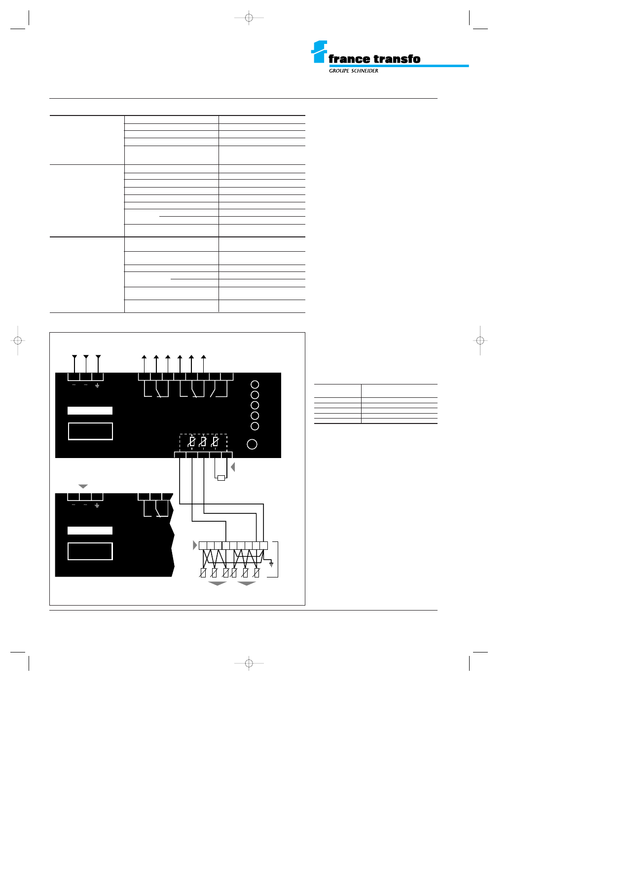
2 PTC sensors assemblies, each one
comprising three positive temperature
coefficient thermistors connected in series.
The first one gives an alarm signal at 150°C
(alarm 1), the second an alarm signal at 160°C
(alarm 2).
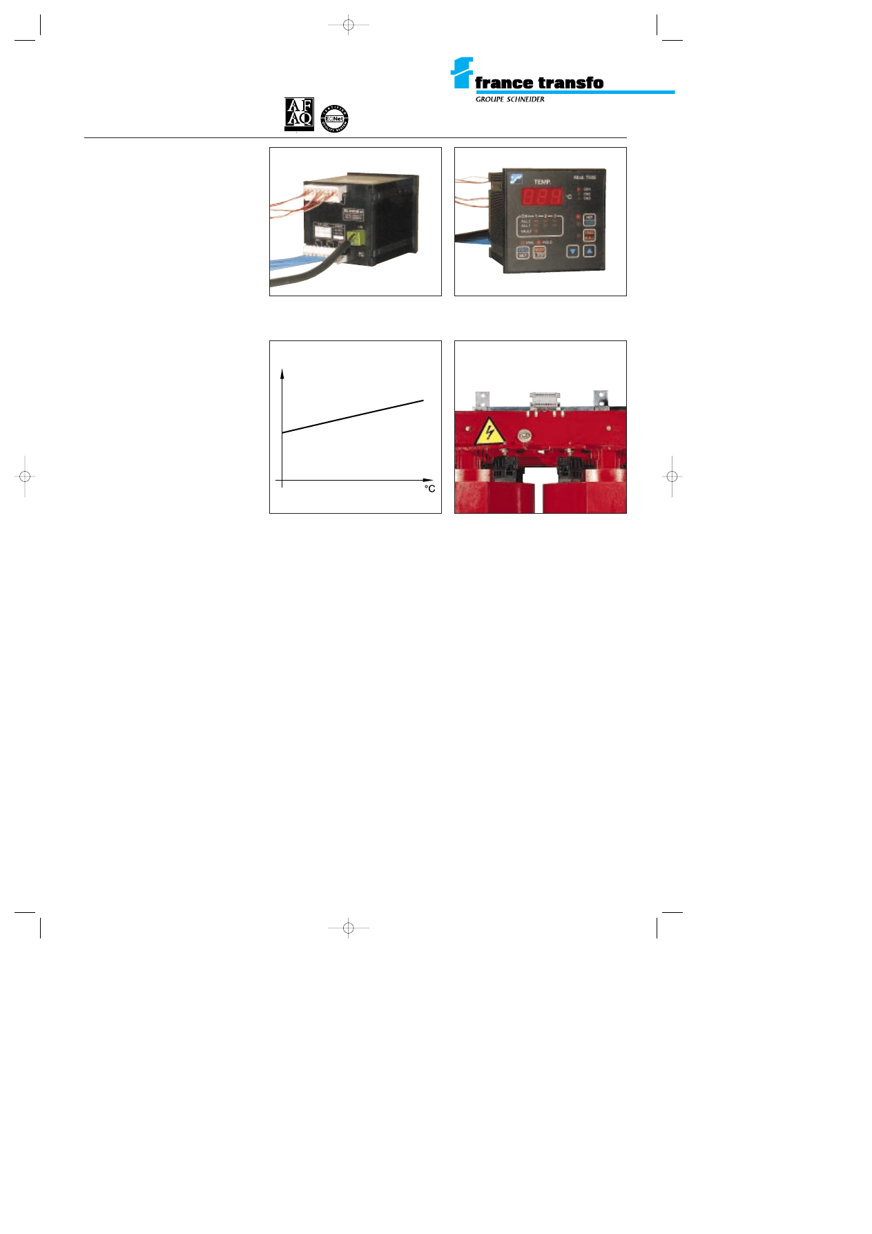
The PTC sensor abruptly changes its resistance
value at its operating temperature threshold.
This is preset during manufacture and not
adjustable. The rapid increase in resistance of
the sensors at their operating temperature is
detected by the Z electronic converter, to
which they are connected. Sensors, one for
alarm 1 and one for alarm 2 per phase are
located in tubes between the magnetic core
and the LV winding and can be withdrawn and
replaced should this ever be necessary.
m
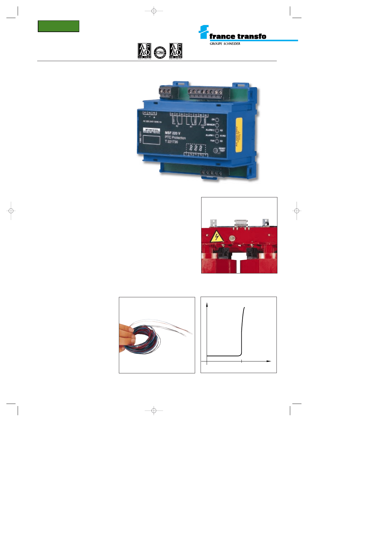
1 A Z electronic converter with
3 independent metering circuits.
Two of these circuits respectively control the
variation in resistance between the 2 PTC
sensor units. When the temperature reaches
150° C (or 160° C), information from Alarm 1 (or
Alarm 2) is respectively processed by the
2 independent output relays equipped with a
changeover switch contact; the position of
these two relays is signalled by 2 red coloured
LED’s.
The third metering circuit is shunted by an
external or enclosure mounted resistance R; it
can control a 3
rd
PTC sensor unit at 140° C as
long as this resistance is eliminated. In this
case (“Forced Air” option on request), the FAN
information is processed by a 3
rd
independent
output relay equipped with a closing contact;
the position of this relay is signalled by a yellow
LED.
In case of the failure of one of these 3 probe
circuits (breaking or short-circuit), a red
coloured LED marked SENSOR flashes,
together with that of the incriminating circuit.
A green coloured LED signals the presence of
voltage to the enclosure.
m
a terminal board with plug-in connectors
in order to connect the PTC sensors to the
electronic converter.
The PTC sensors are supplied connected to
the terminal board fixed on the upper core
clamp of the transformer.
HV/LV distribution transformers
TRIHAL cast resin transformers
thermal protection by PTC sensors
normal
temperature
W
resistance
¡
C
0
k
PTC sensors
Z electronic converter
terminal-board with plug-in connectors
connecting the PTC sensor and the Z
electronic converter
characteristic curve diagram of a PTC sensor
GEa105g 22/07/98 9:51 Page 1
HV/LV distribution transformers
TRIHAL cast resin transformers
thermal protection by PTC sensors
N°
Ident. TV
A
: FR 78 357801109 • Edition France T
ransfo - Limited company - Social capital 10 280 000 FRF - RCS Metz B 357 801 1
09 • Printed in France • Composition and illustrations: COREDIT • 07/98
connection diagram
of the Z thermal protection module
(usual case of utilization)
Shown unenergized
power supply
Monitoring circuits have to be supplied from an
auxiliary supply (standard: AC 220 to 240 V). If no
suitable supply is available they may be supplied
from the transformers secondary voltage.
installation
Z converter should never be installed on the
transformer or inside its metal enclosure
due to the limit on operating temperature
(see table opposite).
m
it can be installed in the low voltage switch-
board or on a wall in a vertical or horizontal
position (see table opposite for fixing details).
m
it is advised, especially for an installation in
a low voltage switchboard, to keep a minimal
clearance of 2 cm to other equipment or heat
sources and to ensure adequate ventilation.
Take care also to the highest voltage
according to insulation voltage.
m
connections :
The PTC sensors are supplied connected to the
terminal board fixed on the upper core clamp of
the transformer. The wiring from to the terminal
board of the electronic converter is not supplied
by France Transfo (see chart opposite).
the following guidelines in connection
wiring should be followed :
- maximum length
of connection : ........................ 40 metres
- minimum conductor area :...... 0.5 sq mm
- screened cables should be used if wiring
passes near power conductors.
- terminal tightening : 0.5 Nm max.
- no fixings should be made on the
transformer.
- the following minimum clearances to live
conductors must be maintained:
Z converter technical data
monitoring circuits
supply voltage
(1)
AC 230 V*
tolerance voltage
– 15 % to + 10 %
frequency
48 to 62 Hz
input
< 5 VA
maximum resistance of a
PTC sensors circuit before
< 1500 W
operation of the converter
output contacts :
maximum switching voltage
AC 415 V
alarm 1 and alarm 2
maximum switching current
5 A
switching power
AC 2000 VA (ohmic load)
continuous rated current
AC 2 A
rated service current
AC 2 A under 400 V
advised above fuse
4 A rapid
contact life mechanical
3 x 10
7
operations
electrical
10
5
operations
contacts load reduction ratio
0.50 max
with power factor = 0.30
Z electronic
admissible ambient
0°C to + 55° C
converter
temperatures range
dimensions
90 x 105 x 60 mm
(H x L x P)
weight
250 g
protection index
terminal board
IP 20
protective housing
IP 20
maximum capacity on a terminal
1 x 2.5 mm
2
rigid
connection
fixing
either on a DIN 35 mm rail
or with M4 screw
TRIHAL
transformer
3 monitoring
circuit shunted
by resistor (on
request, 140
¡ C
PTC sensors for
fan).
AC 220-240V 50/60 Hz
ON
SENSOR
ALARM 2
ALARM 1
FAN
RESET
TEST
K0
K0/K0
K2
T
T
T2
K2
A1
A2
PE
24
21
22
14
11
12
08
05
K1
K0
T1
T0
1085 1211
Alarm 2
Alarm 1
Fan/Al1
Schwäb.Hall / Germany
MSF 220 V
PTC Protection
T 221736
ZIEHL
supply of
monitoring
circuits
Alarm 2
160
¡ C
Alarm 1
150
¡ C
rd
terminal
board
3 PTC
sensors
Alarm 2
3 PTC
sensors
Alarm 1
1
2
3
4
5
6
7
8
9
R
Mind the polarity,
in DC !
AC/DC 24-240V 50/60 Hz
K2
A1
(–)
(+)
A2
PE
24
21
1085 1203
Alarm 2
Schwäb.Hall / Germany
MSF 220 VU
PTC Protection
T 221735
ZIEHL
22
(1) must be specified at the order
* standard version. Other voltage on request: AC/DC 24 to 240 V, tolerance ± 15 %.
Due to the evolution of standards and materials, the present
document will bind us only after confirmation from our technical
department.
France Transfo
BP 10140
F 57281 Maizières-lès-Metz Cedex
tel. (+33) 03 87 70 57 57 - fax (+33) 03 87 51 10 16
Ref : GEa 105 g
system highest
minimum clearance
voltage (kV)
(mm)
7.2
270
12
450
17.5
450
24
450
36
650
GEa105g 22/07/98 9:51 Page 2
An optional thermal protection module is avail-
able on request for Trihal cast resin transformers.
This will monitor the temperature of the windings
and prevent overheating.
the standard, T thermal
protection module comprises:
m
PT 100 sensors
The main feature of the PT 100 is that it gives
the temperature in real time progressively from
0°C to 200°C -see the graph opposite
(accuracy +/- 0,5 %, i.e. on the measurement
scale +/-1 deg.).
The temperature is monitored and displayed by
a digital thermometer. The 3 sensors, each
comprising one white and two red wires, are
located in tubes between the magnetic core
and the LV winding, on each phase. So they
can be withdrawn and replaced as and when
necessary.
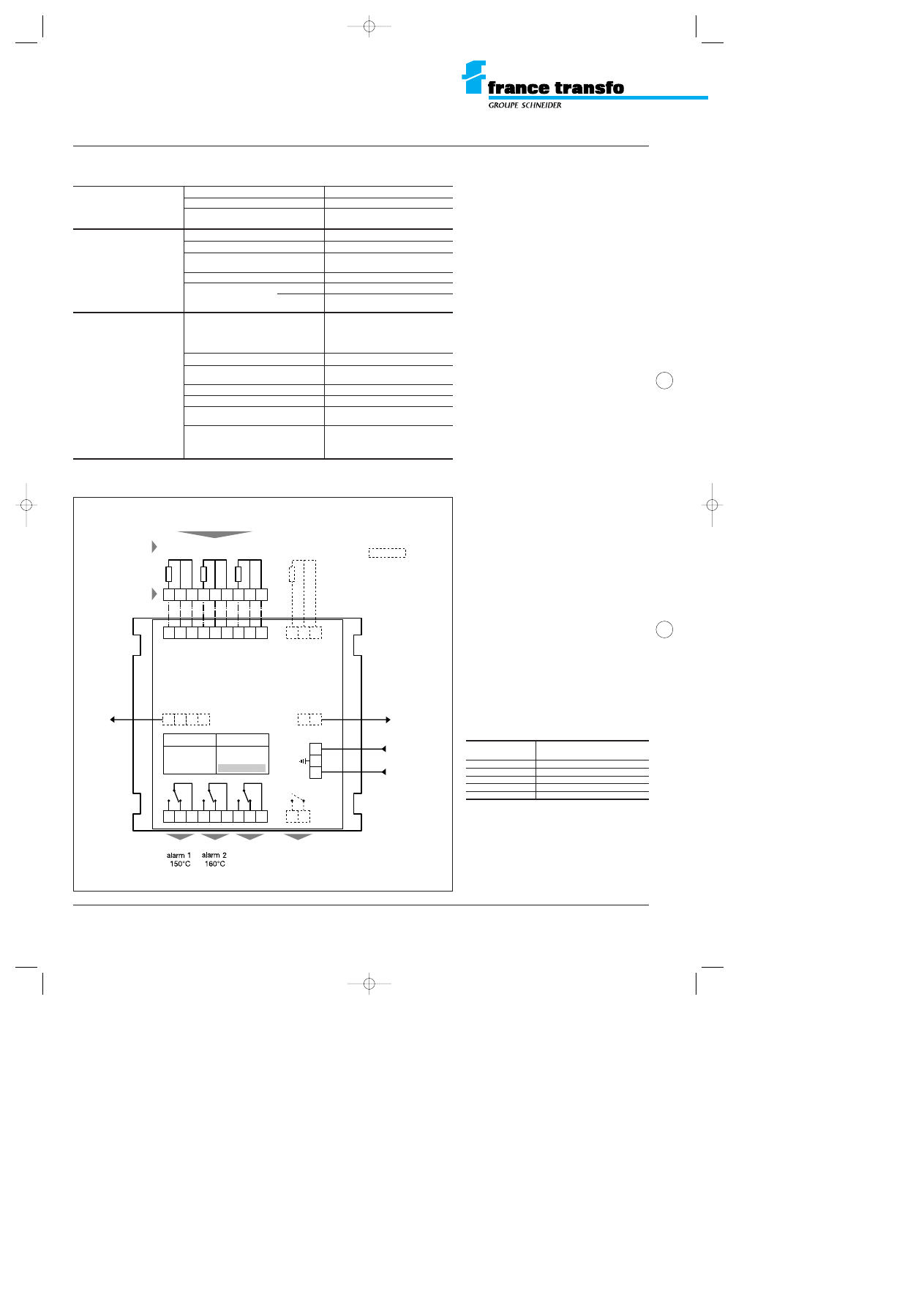
m
1 T digital thermometer, featuring three
independent circuits.
Two of the circuits monitor the temperature read
by the PT 100 sensors, one for alarm 1 and one
for alarm 2.
When the temperature reaches 150 °C (or
160 °C) alarm 1 (or alarm 2) information is
processed by two independent output relays
fitted with change-over switches. The status of
these relays is displayed by two red coloured
diodes (LED).
The third circuit monitors for sensor faults or
breaks in power supply. The corresponding relay
(FAULT), which is independent and fitted with
change-over switches, is instantly switched on
when power is connected to the device.
Its status is also displayed by a red coloured
diode.
The T digital thermometer is delivered with full
instructions for installation and use.
m
1 terminal block to connect the PT 100
sensors to the T digital thermometer.
The block is equipped with a plug-in connector.
The PT 100 sensors are delivered pre-connec-
ted to the terminal block attached to the upper
part of the transformer.
options
The following extras can be fitted to the
T thermal protection module:
m
1 additional sensor to be placed on the
transformer or in the local vicinity.
m
ventilation system control
- 1st ventilation (1st relay)
- 2nd ventilation (2nd relay): external to the
transformer.
m
1 analog output with serial RS 232/485/
INTRS/4-20 mA for the hottest channel.
HV/LV distribution transformers
Trihal cast resin transformers
T thermal protection module
with PT 100 sensors
T digital thermometer
terminal block connecting the T digital
thermometer to the PT 100 sensors
characteristic temperature curve given
by a PT 100 sensor
connections to the T digital thermometer
A F A Q N 1 9 9 0 / 1 1 3 b
I S O 9 0 0 1
temperature
W
resistance
k
GEa.106 b 22/07/98 14:56 Page 1
HV/LV distribution transformers
Trihal cast resin transformers
T thermal protection module
with PT 100 sensors
power supply
Monitoring circuits have to be supplied from an
auxiliary supply (standard: 24 to 220 V AC/DC).
If no suitable supply is available they may be
supplied from the transformer’s secondary
side. To avoid the “FAULT” relay tripping, it is
fitted with a time delay.
Warning: when the device is supplied directly
from the transformer’s secondary side, it is
necessary to protect it from possible over-
voltages that could damage the electronic
circuit. We recommend to use our surge-limiter
PT 73-120 or PT 73-220 (220 V CA).
installation
The T thermometer should never be installed
on the transformer or inside its metal
enclosure due to its operating temperature
limits (see table opposite).
m
it can be installed in the low voltage switch-
board (or on a wall) either horizontally or vertical-
ly (see table opposite for fixing details).
m
it is recommended, especially for an install-
ation in an LV switchboard, to retain a mini-
mum clearance to other equipment (take into
account the highest voltage) or heat sources
and ensure adequate ventilation. Take care
also to the highest voltage according to the
insulation distances.
m
connections:
PT 100 sensors are to be connected to the T
digital thermometer between the connecting
terminal attached to the transformer and the T
digital thermometer’s plug-in connector.
It is not supplied by France Transfo.
See diagram opposite.
Warning: since the transformer is of thermal
class F, the T digital thermometer must be
programmed with a maximum temperature of
150 °C for alarm 1 (L1) and 160 °C for alarm 2
(L2). France Transfo is in no way liable for any
damage to the transformer should these
maximum temperatures not be complied with.
The following conditions must be complied
with
- use screened and braided cables
(20 twists/meter)
- minimum conductor cross-section: 1 mm
2
- wiring should not pass near power circuits
- maximum length of connection: 300 m
- minimum clearances to live parts: see above.
- wiring should not be attached to any live part
of the transformer
- the LV panel should be earthed.
T digital thermometer - technical data
conformity with standards IMQ - VDE - UL - CEE
monitoring circuits
supply voltage
(1)
24 V to 220 V AC/DC
frequency
50-60 Hz AC/DC
power consumption
10 VA AC/DC (40 VA pick up)
output contacts:
maximum switching voltage
250 V AC
alarm 1 and alarm 2
maximum switching current
5 A (resistive circuit)
rated continuous /
2 A at 220 V AC/DC
service current
recommended upstream fuse rating 3 A
contact life
mechanical
2 x 10
7
operations
electrical
5 x 10
5
h/85°C
T digital thermometer
operating conditions
admissible ambient
– 20° C to + 60° C
temperature range
max. ambient humidity
90% RH (non condensable)
dimensions
96 x 96 x 130 mm
(H x L x P)
weight
520 g
casing protection index
IP 54 self extinguishing
maximum capacity
2.5 mm
2
on a terminal connection
fixing
locating recess 92 x 92 mm,
suppliance of two pressure clips
on the rear side.
N°
ident. TV
A
: FR 78 357801109 • Edition France T
ransfo – Limited company - Social capital 10 280 000 FRF – RCS Metz B 357 801 1
09 • Printed in France • Composition and illustrations: COREDIT • 10/96
S.N. /DATE
POWER
24-220 V
AC / DC
1
2
3
4
70 71
72
73
13 14
15
16 17
18 19 20
21
22 23
24
50
51
5
6
7
8
9
10 11
42
41
40
1
2
3
4
5
6
7
8
9
A
CH1
B
CH2
C
CH3
CH4
T - 935
terminal block
mounted on
the transformer
transformer
columns
PT100 sensors mounted
on the transformer
OPTIONS
not included
in the standard
“France Transfo” offer
FAN 2
secondary
ventilation
(external to
the transformer)
24-220 V
AC/DC
power supply
ALL 1
ALL 2
FAULT
FAN 1
sensor
fault
monitor
primary
ventilation
4-20 mA
output
white
red
red
Due to the evolution of standards and materials, the present
document is only binding subject to confirmation by our
technical department.
France Transfo
BP 10140
F 57281 Maizières-lès-Metz Cedex
tel. (+33) 03 87 70 57 57 - fax (+33) 03 87 51 10 16
Ref : GEa.106 b
(1) universal supply irrespective of polarity.
connection diagram
for the T digital thermometer
insulation
minimum clearance
(kV)
(mm)
7,2
270
12
450
17,5
450
24
450
36
650
advised by France Transfo
GEa.106 b 22/07/98 14:56 Page 2
Document Outline
Wyszukiwarka
Podobne podstrony:
10 TRIHAL HV LV TRANSFOR INSULATION
10 TRIHAL TECHN MANUAL
2 regulacja napiecia modelu transformator zaczepy, aaa, studia 22.10.2014, Materiały od Piotra cukro
L 10 Linear transformations I
1 2 Transformacja pl rynku medialnego 9 16 10
LV, HV Lebensmittelverschwendung
Transformator telekomunikacyjny [lab] 1999 10 19 (2)
10 Transformacja ustrojowa w Polsce po 1989roku
10 Wielka Globalna transformacja
Transformator telekomunikacyjny [lab] 1999 10 19
Transfigurations 6 10
11 HV HV POWER OIL TRANSFO
10 22 TRANSFORM THE SENTENCES
Transformator telekomunikacyjny [lab] 1999 10 19 (3)
6822 Protecting your data with Windows 10 BitLocker
więcej podobnych podstron