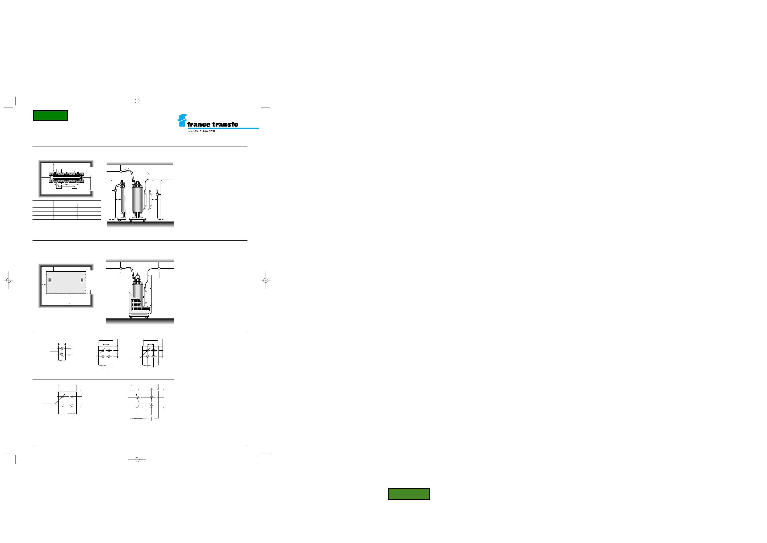
connections
The contrator must ensure that cables and busbars are adequately supported to prevent mechanical stresses from being imposed on the transformer terminals, busbars or bushings.
200 mm
500 mm (2)
200 mm
200 mm
LV
HV
HV
n
LV
cable support
cable support
minimum clearances required
HV and LV connection
HV/LV distribution transformers
TRIHAL cast resin transformers
160 to 3150 kVA
insulation level
< 24 kV - low voltage 400 V
X
X
X (1)
X
120
mini
cable support
HV
LV
n
120
mini
insulation
dimensions X (mm)
(kV)
full wall
grid wall
7.2
90
300
12
120
300
17.5 - 24
220
300
minimum clearances required
HV and LV standard connection
The contrator must ensure that cables and busbars are adequately
supported to prevent mechanical stresses from being imposed on
the transformer terminals, busbars or bushings.
(2) 500 mm. for an access to tapping on the HV side,
but 200 mm. minimum.
(1) Don’t take into account the access to tapping on the HV side.
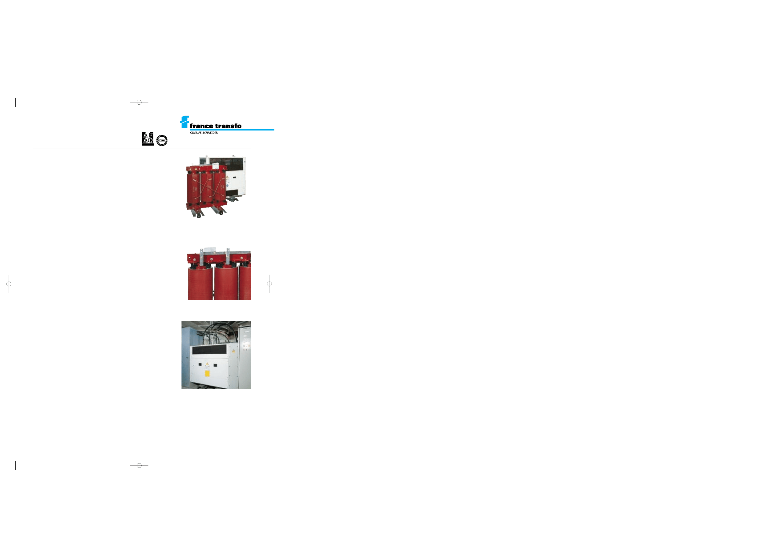
TRIHAL transformers without
enclosure housing (IP00)
The winding resin coating and the plug-in
connectors don’t ensure any protection against
touch when the transformer is energized.
TRIHAL transformers with
IP31 metal enclosure
LV terminations
40
Ø 14
15
33
33
80
4 x Ø 14
23,5
33
50
100
4 x Ø 14
25
50
80
40
160
4 x Ø 16
35
50
33
70
4 x Ø 14
23,5
33
160 to 500 kVA*
thickness 5
630 to 800 kVA*
thickness 6
1000 to 1250 kVA*
thickness 10
1600 kVA*
thickness 12
2000 kVA*
thickness 10
*Valables pour 400 et 410 V en aluminium.
GEa.26 e 23/07/98 8:30 Page 1
<< Back
HV/LV distribution transformers
TRIHAL cast resin transformers
160 to 3150 kVA
insulation level
< 24 kV - low voltage 400V
France Transfo
B.P. 10140
F 57281 Maizières-lès-Metz cedex
tel. (33) 87 70 57 57
telex 860 418 F
fax (33) 03 87 51 10 16
Due to the evolution of standards and materials, the present
document will bind us only after confirmation from technical
department.
Edition France Transfo
Conception: COREDIT
04/97 - printed in France
ref. GEa.26 e
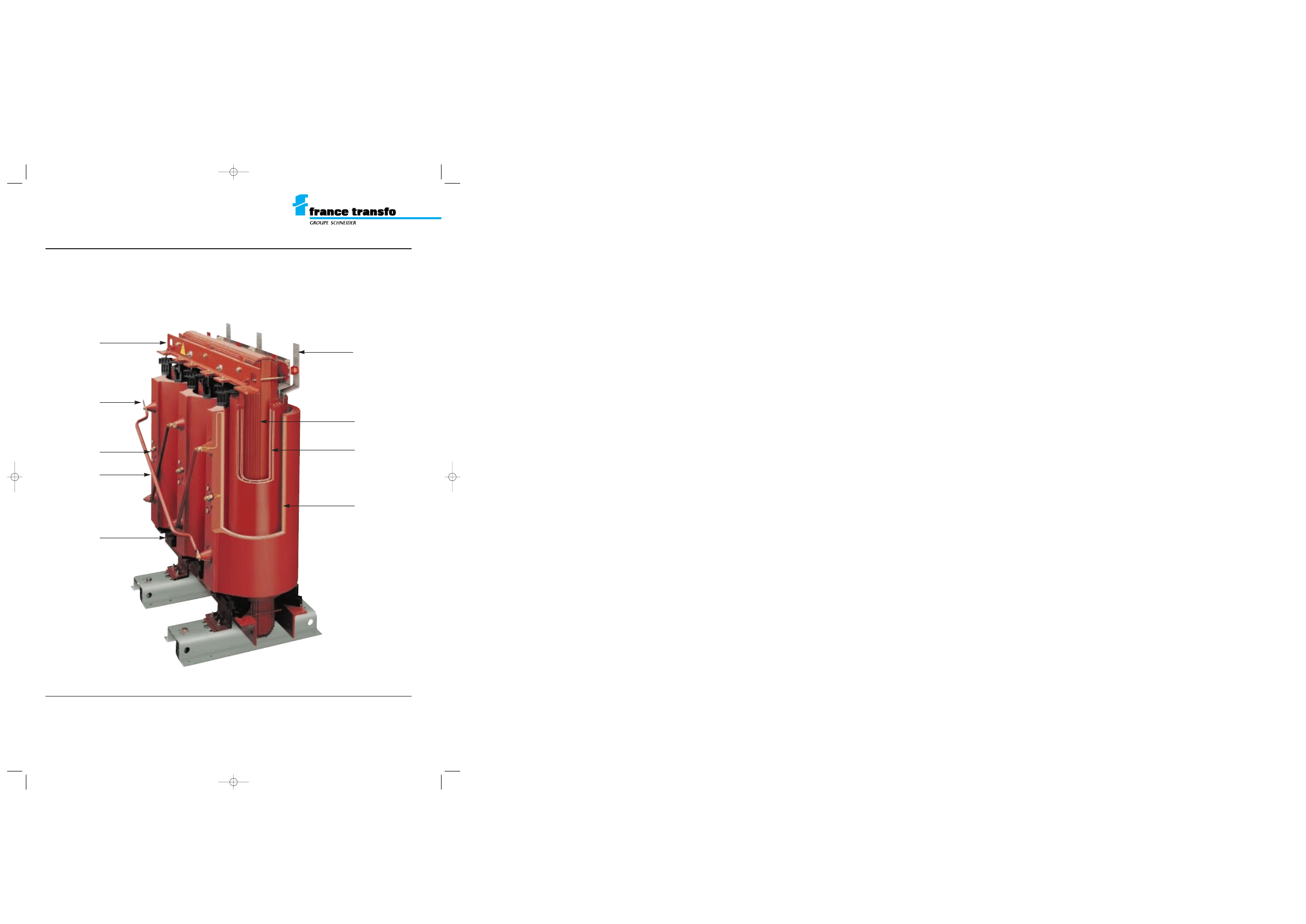
lifting hole
HV winding
HV connection
terminal
tappings
connection bar
earthing terminal
LV winding
magnetic core
LV connection
terminal
GEa.26 e 23/07/98 8:30 Page 2
HV/LV distribution transformers
TRIHAL cast resin transformers
160 to 3150 kVA
insulation level
< 24 kV - low voltage 400 V
description
This range comprises transformers in accord-
ance with the following specifications :
m
50 Hz three-phase transformers for indoor
installation (outdoor installation or other
frequency on request);
m
cast resin dry type;
m
thermal class F;
m
ambient
< 40°C, altitude < 1000m
(1)
;
m
natural air cooling type AN;
m
LV winding usually made of aluminium sheet
(insulated strip for low ratings). The core and LV
windings assembly is given an additional
protective coating of alkyd resin;
m
HV winding manufactured from insulated
round wire or rectangular strip;
m
HV winding is vacuum cast in epoxy
resin
(2)
efficiently fireproofed with trihydrat-
ed alumina ;
TRIHAL transformers can be supplied:
m
without enclosure (IP00).
The installer must ensure that access to the live
core and windings is prevented
(3)
;
m
with IP31 metal enclosure.
It prevents direct contact with live components.
standards
These transformers are in accordance with
standards:
m
IEC 76-1 à 76-5;
m
IEC 726 (1982);
m
CENELEC (European Committee for Electro-
technical standardization) harmonization
documents HD 538-1 S1:1992 and HD 464 S1:
1988 / A2: 1991 /A3:1992 concerning dry type
transformers.
standard equipment
TRIHAL without enclosure (IP00):
m
4 flat bi-directional rollers;
m
4 lifting holes;
m
haulage holes on the underbase;
m
2 earthing points;
m
1 rating plate (on HV side);
m
1 warning label “electricity danger ”;
m
HV voltage variation by off circuit tapping
links ;
m
HV connection bars for connection from
above ;
m
LV pre-drilled terminations on above ;
m
1 routine test certificate and 1 instruction
leaflet for installation commissioning and
maintenance;
TRIHAL with IP31 metal enclosure:
m
TRIHAL without enclosure (IP00) as above;
m
IP31 integral metal enclosure (except the
bottom: IP21):
M
with standard anti corrosion protection;
M
lifting lugs for transformer and enclosure
assembly ;
M
access to tappings on the HV side by
removing a bolted panel which is fitted with
handles, warning label, rating plate and a
visible braid for earthing ;
M
blanked off holes provided for fitting Ronis
ELP1 or alternatively Profalux P1 locks on the
HV tapping access panel ;
M
2 gland plates, one on the HV and one on the
LV side. These may be removed and drilled to
take cable glands which are not supplied ;
M
1 flap door in the base on the HV side to
permit HV cable entry. Connection made to top
of delta bars.
options
The following fittings can be provide:
m
1 thermal protection module comprising
6 PTC thermostatic sensors (2 per phase)
connected to a terminal board with a plug-in
connector and an electronic converter with 2
contacts (alarm 1 and alarm 2) supplied
separately;
m
3 HV plug-in connectors (HN 52 S 61) may
be used as follows:
M
fixed on a mounting plate from the upper
core clamp (TRIHAL IP00);
M
fixed on top of the transformer enclosure on
the HV side (TRIHAL IP 31);
m
straight or elbow connectors can also be
supplied. Please state cable characteristics;
m
additional LV terminal plates (tinned copper);
m
1 locking device to secure plug-in bushings
(without lock and indiscriminitely suitable for a
Ronis EPL11AP, ELP1, ELP2 or Profalux P1,
P2, V1, V21 lock mounting);
m
forced cooling by fans to give an AF rating
of 140 %.
Nota : These options are those usually
specified and many alternatives can be
provided on request.
(1) Please state when ambient > 40°C or altitude > 1000 m.
(2) a casting system developped and patented by France
Transfo.
(3) when the transformer is energized, the winding resin coa-
ting and the heat shrinkable protection of the HV connection
bars do not ensure any protection against touch.
250 kVA (IP00) 20 kV/400 V +
400 kVA (IP31) 20 kV/400 V
630 kVA - 20 kV/400 V
A F A Q N 1 9 9 0 / 1 1 3 b
I S O 9 0 0 1
LV pre-drilled terminations
GEa.26 e 23/07/98 8:31 Page 3
rated power (kVA)
(1) (
*
)
160
(2)
250
315
(2)
400
500
(2)
630
800
1000
1250
1600
2000
2500
3150
rated primary voltage
(1)
20 kV
rated insulation level
(3)
24 kV
frequency
(1)
50 Hz
maximum ambient temperature
40°C
secondary voltage at no load
(1)
400 V
HV tapping range (off-circuit)
(1)
± 2.5 %
vector group
Dyn 11 (delta, star neutral brought out)
losses
no load losses
650
880
1030
1200
1400
1650
2000
2300
2800
3100
4000
5000
6300
(W)
at 75°C
2300
3300
4000
4800
5700
6800
8200
9600
11500 14000 17500
20000
23000
load losses
at 120°C
2700
3800
4600
5500
6500
7800
9400 11000
13100 16000 20000
23000
26000
rated impedance voltage (%)
6
6
6
6
6
6
6
6
6
6
6
6
7
no-load current (%)
2.3
2
1.8
1.5
1.5
1.3
1.3
1.2
1.2
1.2
1.1
1
1
switching current
Ie/In (peak value)
10.5
10.5
10
10
10
10
10
10
10
10
9.5
9.5
9.5
time constant
0.13
0.18
0.20
0.25
0.25
0.26
0.30
0.30
0.35
0.4
0.4
0.5
0.6
noise level
(4)
acoustic power L
WA
62
65
67
68
69
70
72
73
75
76
78
81
81
dB(A)
acoustic pressure L
PA
at 1 metre
50
53
55
56
56
57
59
59
61
62
63
66
65
rated power (kVA)
(1) (
*
)
160
(2)
250
315
(2)
400
500
(2)
630
800
1000
1250
1600
2000
2500
3150
rated primary voltage
(1)
5 to 12 kV (dual voltage on request)
rated insulation level
(3)
7.2 kV for 5.5 kV - 12 kV for 10 kV
frequency
(1)
50 Hz
maximum ambient temperature
40°C
secondary voltage at no load
(1)
400 V between phases, 231 V phase to neutral
HV tapping range (off-circuit)
(1)
± 2.5 %
vector group
Dyn 11 or Dyn 5 (delta, star neutral brought out)
losses
no-load losses
610
820
950
1150
1300
1500
1700
2000
2500
2800
3500
4300
5500
(W)
at 75°C
2300
3100
3600
4300
5200
6400
7700
8800
10500 12300 14900
18300
22000
load losses
at 120°C
2700
3500
4100
4900
6000
7300
8800 10000
12000 14000 17000
21000
25000
rated impedance voltage (%)
4
4
4
4
4
4
6
6
6
6
6
6
7
no-load current (%)
2.3
2.
1.8
1.5
1.5
1.3
1.3
1.2
1.2
1.2
1.1
1
1
switching current
Ie/In (peak value)
13.5
13
13
13
13
12
9
9
9
9
9.5
8.5
8.5
time constant
0.13
0.18
0.20
0.25
0.25
0.26
0.30
0.34
0.35
0.42
0.4
0.5
0.6
noise level
(4)
acoustic power L
WA
62
65
67
68
69
70
72
73
75
76
77
81
81
dB(A)
acoustic pressure L
PA
at 1 metre
50
53
55
55
56
57
59
59
61
61
61
65
65
HV/LV distribution transformers
TRIHAL cast resin transformers
160 to 3150 kVA
insulation level
< 24 kV - low voltage 400 V
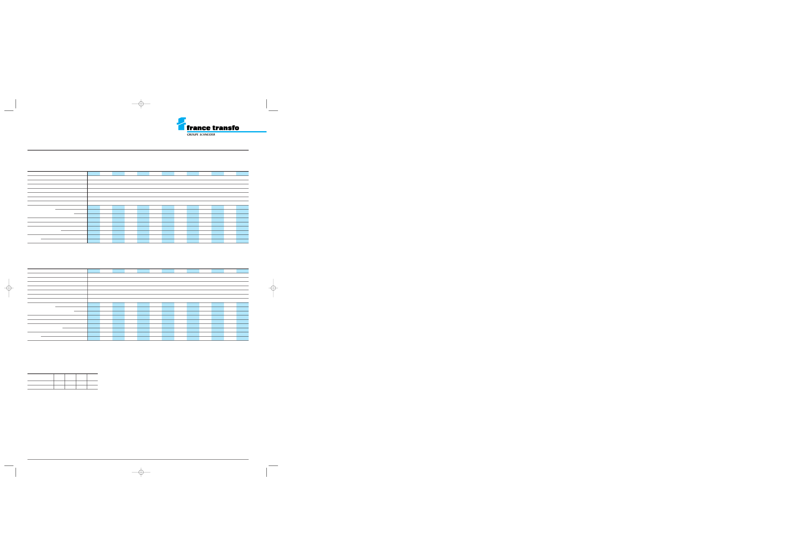
insulation level : 7.2 kV and 12 kV
electrical characteristics
insulation level : 17.5 kV and 24 kV
(
*
)
the rated power is defined by natural air cooling (AN).
Should there be particular constraints, it may be increased by
40 % by forced cooling addition (AF). Please consult us.
(1) other possibilities upon request, consult us.
(2) non standard ratings available on request.
(3) reminder of insulation levels :
(4) according to CEI 551
rated insulation
7.2
12
17.5
24
level (kV)
kV r.m.s. 50 Hz - 1 mn
20
28
38
50
kV B.I.L. 1.2/50 µs
60
75
95
125
GEa.26 e 23/07/98 8:31 Page 4
rated power (kVA)
(1) (
*
)
160 250
315
400
500 630
800
1000
1250
1600
2000
2500
3150
dimensions
(mm)
A
990
1070
1160
1230
1260
1340
1380
1520
1590
1710
1900
2150
2200
B
665
680
795
795
795
800
810
945
945
945
1195
1195
1195
C
1330
1370
1410
1400
1600
1630
1610
1670
1830
1940
2250
2350
2600
D
520
520
670
670
670
670
670
820
820
820
1070
1070
1070
E
650
650
800
800
800
800
800
950
950
950
1200
1200
1200
H
170
160
210
200
200
180
180
230
220
200
230
230
300
I
350
360
380
390
390
410
410
430
440
460
460
470
460
J
330
360
390
410
420
450
460
500
530
570
630
640
690
L
200
210
230
230
240
250
260
280
280
250
280
280
380
M
860
900
940
920
1050
1070
1110
1180
1440
1540
1700
1750
1750
weights
(kg)
770
950
1150
1360
1580
1820
1880
2360
2710
3400
4800
5800
7300
HV/LV distribution transformers
TRIHAL cast resin transformers
160 to 3150 kVA
insulation level
< 24 kV - low voltage 400 V
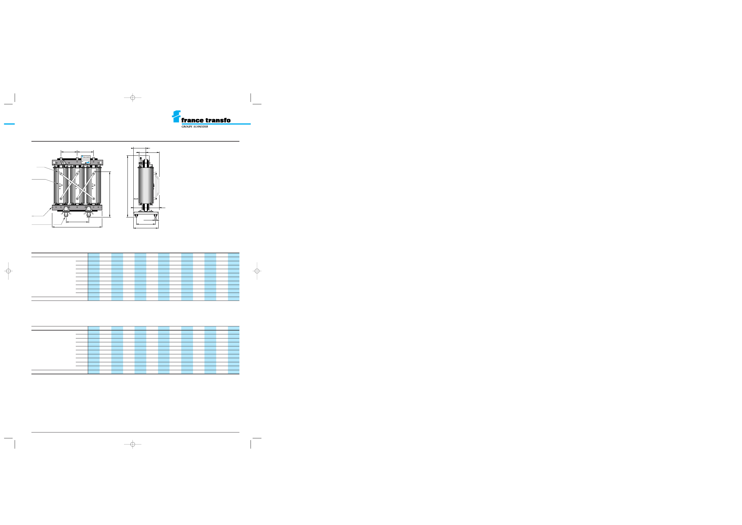
dimensions and weights
TRIHAL transformers without
enclosure housing (IP00)
7.2 to 24 kV / 400 V
Dimensions and weights indicated in the table
below are provided as an example for primary
single voltage transformers 7.2 to 24kV / 400V.
They apply to transformers with electrical
characteristics shown in the previous table.
For other voltages, impedance voltages and
dual-voltages, weights and dimensions are
different (consult us).
D
M
C
E
D
I
A
earthing
terminal
tapping
links
J
J
L
E/2
B
Ø 125
(200)
40
(70)
H
Ø 13
Groupe Merlin Gerin · Usine d’Ennery (Moselle) France
insulation level : 7.2 kV and 12 kV - low voltage 400 V
rated power (kVA)
(1) (
*
)
160 250
315
400
500 630
800
1000
1250
1600
2000
2500
3150
dimensions
(mm)
A
1070
1140
1170
1230
1300
1340
1400
1560
1610
1700
1950
2030
2200
B
680
690
795
795
795
800
805
945
945
945
1195
1195
1195
C
1320
1350
1510
1490
1580
1690
1720
1920
2030
2170
2380
2440
2600
D
520
520
670
670
670
670
670
820
820
820
1070
1070
1070
E
650
650
800
800
800
800
800
950
950
950
1200
1200
1200
H
160
150
220
210
190
190
180
230
220
210
290
290
300
I
360
370
370
380
400
400
410
430
440
460
450
460
460
J
360
380
390
410
440
450
470
510
530
560
630
640
690
L
180
180
190
200
210
210
220
250
250
260
310
320
380
M
890
930
1090
1070
1110
1210
1240
1410
1510
1650
1770
1750
1750
weights
(kg)
780
950
1140
1290
1520
1730
1990
2480
2810
3430
4720
5980
7300
insulation level : 17.5 kV and 24 kV - low voltage 400 V
In brackets, dimensions from 1000 up to 3150 kVA.
GEa.26 e 23/07/98 8:31 Page 5
HV/LV distribution transformers
TRIHAL cast resin transformers
160 to 3150 kVA
insulation level
< 24 kV - low voltage 400 V
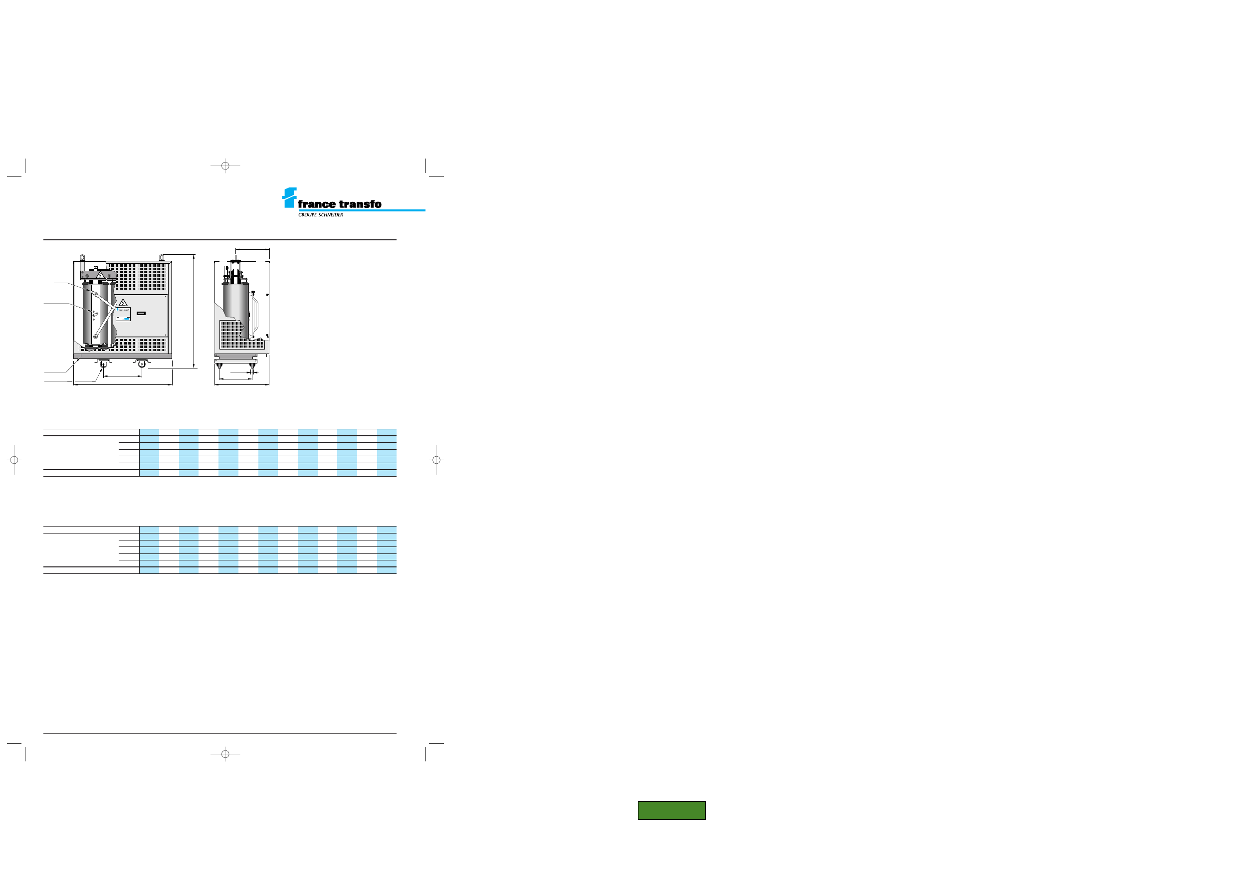
dimensions and weights
TRIHAL transformers with IP31
metal enclosure
7.2 to 24 kV / 400 V
D
C
B
D
I
A
earthing
terminal
Ø 125
(200)
40
(70)
Ø 13
tapping
links
nº 217840
Groupe Merlin Gerin · Usine d’Ennery (Moselle) France
Dimensions and weights indicated in the table
below are provided as an example for primary
single voltage transformers 7.2 to 24kV / 400V.
They apply to transformers with electrical
characteristics shown in the previous table.
For other voltages, impedance voltages and
dual-voltages, weights and dimensions are
different (consult us).
insulation level
<
12 kV - low voltage 400 V
insulation level
<
24 kV - low voltage 400 V
In brackets, dimensions from 1000 up to 3150 kVA.
rated power (kVA)
(1) (
*
)
160 250
315
400
500 630
800
1000
1250
1600
2000
2500
3150
dimensions
(mm)
A
1390
1480
1530
1550
1570
1620
1650
1880
1820
2080
2200
2550
2450
B
875
895
920
945
955
975
935
1020
1020
1040
1300
1300
1350
C
1680
1750
1760
1780
1840
2000
1920
2050
2150
2360
2850
3000
2900
D
520
520
670
670
670
670
670
820
820
820
1070
1070
1070
I
520
530
550
560
560
580
580
650
630
640
700
710
850
weights
(kg)
960
1150
1360
1580
1810
2060
2120
2620
2990
3750
5340
6340
7900
rated power (kVA)
(1) (
*
)
160 250
315
400
500 630
800
1000
1250
1600
2000
2500
3150
dimensions
(mm)
A
1380
1430
1530
1530
1540
1560
1600
1710
1760
1860
2100
2120
2450
B
850
865
875
890
910
920
935
1020
1020
1030
1265
1265
1350
C
1560
1590
1750
1730
1820
1930
1960
2160
2270
2410
2660
2710
2900
D
520
520
670
670
670
670
670
820
820
820
1070
1070
1070
I
530
540
550
560
570
570
580
650
640
630
710
820
850
weights
(kg)
960
1140
1340
1500
1740
1960
2230
2740
3080
3760
5200
6510
7900
GEa.26 e 23/07/98 8:31 Page 6
<< Back
Document Outline
Wyszukiwarka
Podobne podstrony:
10 TRIHAL HV LV TRANSFOR PTC PROTECTION
10 TRIHAL TECHN MANUAL
2 regulacja napiecia modelu transformator zaczepy, aaa, studia 22.10.2014, Materiały od Piotra cukro
L 10 Linear transformations I
1 2 Transformacja pl rynku medialnego 9 16 10
LV, HV Lebensmittelverschwendung
Transformator telekomunikacyjny [lab] 1999 10 19 (2)
10 Transformacja ustrojowa w Polsce po 1989roku
10 Wielka Globalna transformacja
Transformator telekomunikacyjny [lab] 1999 10 19
Transfigurations 6 10
11 HV HV POWER OIL TRANSFO
10 22 TRANSFORM THE SENTENCES
Transformator telekomunikacyjny [lab] 1999 10 19 (3)
Egzamin ósmoklasisty Transformacje 1 10 UPDATED Engly
więcej podobnych podstron