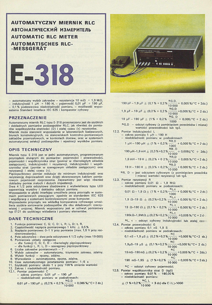
A U T O M A T Y C Z N Y M IE R N IK R LC
ABTOMATMHECKHM H
3
MEPHTEJlb
A U T O M A T IC R LC M ETER
A U T O M A T IS C H E S R L C -
-M E S S G E R A T
E-318
— autom atyczny w yb ó r zakresów - rezystancja 10 m i i > 1,9 M il ,
— indukcyjność 1 (iH + 190 H, — pojemność 0,01 pF + 190 p.F,
— 0,1 % podstaw owa niedokładność pomiaru, - m ożliwość w y p o
sażenia Standard Interface IEC 625 i komparator cyfrow y
P R Z E Z N A C Z E N IE
Autom atyczny miernik RLC typu E-318 przeznaczony jest do szybkich
i dokładnych pom iarów podzespołów RLC, jak również do pom ia
rów współczynnika stratności (D ) i stałej czasu (
t
) rezystorów.
M iernik może stanow ić wyposażenie w laboratoriach badawczych,
biurach konstrukcyjnych, na stanowiskach kontrolno-pom iarow ych
zakładów przem ysłowych, w kontrolach dostaw, oraz w systemach
automatycznej selekcji podzespołów i rejestracji w y n ik ó w pomiaru.
O P IS T E C H N IC Z N Y
M iernik typu E-318 jest w pełni automatycznym, programowanym
przyrządem służącym do pom iarów : pojemności i przewodności,
pojemności i współczynnika strat (pom iar w rów noległym układzie
zastępczym), indukcyjności i rezystancji, indukcyjności i w s p ó ł
czynnika strat (pomiar w szeregowym układzie zastępczym) oraz
rezystancji i stałej czasu (
t
).
Pięciopunktow y pomiar redukuje do minim um indukcyjność oraz
rezystancję doprowadzeń oraz dzięki ekranowanym kablom pom ia
row ym pojemność rozproszenia. Zapewniony jest w ięc również
dokładny pomiar małych i dużych impedancji.
Dwa 4 1 /2 pola odczytow e zbudowane z w yśw ietlaczy typu LED
zapewniają w yraźny i dokładny odczyt pomiaru.
Wyposażenie w płytki interfejsu um ożliwia pracę przyrządu w syste
mach pom iarowych pracującym zgodnie ze standardem IEC 625
i współpracę z systemami kontrolow anym i przez komputer.
Wyposażenie przyrządu w e w kładkę komparatora cyfrow ego um oż
liw ia szybkie sortow anie podzespołów dla obu składow ych: rzeczy
w istej i urojonej. M iernik wyposażony jest w uchw yt pom iarow y
ty p E121 do szybkiego wkładania i pomiaru elementów.
DANE T E C H N IC Z N E
1. Funkcje pom iarowe: C, G; C, D; L, R; L, D;
t ,
R.
2. Częstotliwość napięcia pom iarowego 1 kHz ± 0,5%
3. Napięcie pom iarowe: 0—1 V przy pomiarze (max. 1,5 V przy roz-
rów now ażeniu).
4. Role odczytow e - dw a pola odczytow e 4 1 /2 cyfry (m ax 19 000)
5. Pomiarowe układy zastępcze
- dla fun kcji C, G; C, D - rów noległy pięciopunktow y
- dla fu n k cji L, R; L, D - szeregowy pięciopunktow y
6. Liczba zakresów pom iarowych - 7
7. W ybór zakresów - automatyczny, trzymanie zakresu, zdalny.
8. W ybór fun kcji - ręczny, zdalny.
9. W yzwalanie - automatyczne, ręczne, zdalne.
10. Czas autom atycznego powtarzania pom iaru: 1 -5 s
11. Szybkość pomiaru: około 1 s przy 100% zmianie wartości
12. Zakres i niedokładność pomiaru.
12.1.
Pomiar pojemności C
- zakres pom iaru: 0,01 pF - 190 nF
— niedokładność pomiaru w podzakresach:
NG.D
0,01 pF - 1 9 0 pF ± (0,2 % + 0,2 % —
+ 0,005 % /°C + 2 dz.)
1 0 0 0 0
NG.D.
190 pF - 1,9 nF ± (0,1 % + 0,2 % --------- + 0,005 % /°C + 2dz.)
10
000
NG.D
1,9
jiF — 19 (jF ± (0,2 % + 0,2 % -------+ 0,00 5 % /°C + 2 dz.)
10 000
NG. D
19 nF - 190 uF
±
(1 % + 0 , 2 % ----------+ 0,0 0 5 /°C + 2 dz.)
1000
NG,D - odczyt cyfrow y (z pominięciem przecinków i miana)
wartości przewodności lub tgS.
12.2. Pomiar indukcyjności L
- zakres pomiaru 1 pH - 190 H
- niedokładność pomiaru w podzakresach
NR.D
1 pH - 190 pH ± (1 % + 0,2 % --------- + 0,005 % /°C + 2 dz.)
1000
N R .D
190 p H - 1 ,9 mH ± (0,3 % +0,2 % ------ + 0,005$/°C + 2dz.)
10 000
NR.D
1.9 mH — 19 H ± (0,2% + 0 2 % --------- + 0,005 % /°C + 2 dz.)
10 000
NR.D
19 H - 1 9 0 H ± (0,3 % + 0,2 %
— + 0,005 % /°C + 2 dz.)
10
000
'
NR, D - jest odczytem cyfrow ym (z pom inięciem przecinka
i miana) wartości rezystancji lub t g 8.
12.3. Pomiar rezystancji R
- zakres pomiaru 0,01 i ł - 1,9 M i ł
- niedokładność pomiaru w podzakresach:
NL.t
0,01 i l - 1 , 9 i i ± (1 % + 0 ,2 % ---------- + 0,005 % /°C + 2d z.)
1000
'
N L,t
1.9 f i- 1 9 n
±
( 0 ,2 % + 0 ,2 % ---------- + 0,005 % /°C + 2 dz.)
10
000
N L t
19 f i - 1 90 n ± (0,1 % + 0,2 % ---------- + 0,005 % /°C + 2 dz.1
10 000
NL.r
19 0 k Q -1 ,9 M f i ± (0,2 % +0,2 %
+ 0,005 % /°C + 2 d
10 000
NL,
t
- odczyt cyfrow y indukcyjności lu b stałej cza-
12.4. Pomiar przewodności G
- zakres pomiaru 0,1 nS 1,9 S
- niedokładność pomiaru w podzakresach:
NC
0,1 n S - 1 , 9 p S ± (0 ,2 % + 0 ,2 % --------- +0,005 % /°C + 2 dz.)
10 000
NC
1 ,9 p S -1 9 pS ± (0,1 % +0,2 %---------- + 0,005 % /°C + 2 dz.)
10 000
NC
19 m S -1 90 mS ± (0,2 % + 0,2 % ----------+ 0,005 % /°C + 2dz.)
10 000
NC
190 m S-1,9S ± (1 % +0,2% ----------+ 0,005 % /°C + 2d z.)
1 0 0 0 0
NC - odczyt cyfrow y pojemności.
12.5. Pomiar współczynnika strat D (tgS)
- rekres pomiaru 0,01
%
- 190,00%
- niedokładność pom iaru:
NC, L
± (1 % + 0,2% ---------- + 3 dz) dla C i L > 1 0 0 0
10 000
12.6. Pomiar stałej czasu x
— zakres pomiaru od -1 9 0 ,0 0 do + 190 ,00 pS (dla R > 100)
- niedokładność pomiaru:
NR
± (1 % + 0 ,2 %
;— +3dz.) dla R > 1 0 0 0
10 000
13. Zasilanie 220 V ± 10%, 50 Hz, 70 VA
14. W ymiary: 4 3 8 * 1 4 0 x 3 5 0 mm
15. Masa: ok. 10 kg
W Y P O S A Ż E N IE D O D A T K O W E
(sprzedawane na dodatkow e zam ówienie za oddzielną opłatą)
1. Interfejs IEC 625
Pracę w systemie IEC 625 zapewniają 3 dodatkow e płytki (ZO,
ZN, ZOZ) wkładane do wnętrza przyrządu.
Funkcje interfejsowe: AH 1, L3, RL1 DC1, DT1, T5, SH1, SR1.
2. Komparator cyfrow y: Zbudow any z czterech pięciosegm ento-
w ych nastaw ników (po dwa dla każdego pola odczytow ego)
w form ie w kładki do M iernika E-318.
Ustawiana górna i dolna granica komparacji.
Zakres komparacji: 00 0 0 0 -1 9 9 9 9
Szybkość komparacji 5 ms.
Informacja św ietlna: HI, GO, LO na płycie przedniej.
Sygnał TTL na gnieździe komparatora na płycie tylnej przyrządu.
Sygnał poprzez gniazdo interfejsu.
— aBTOMaTHHecKUH Bbi6op ;0tana30HB, — conpoTm neH H e 10
m
O
m
— 1,9 M O
m
, — HimyKTHBHOCTb 1 n r — 190 F , —- eMKOCTb 0,1 n<l>
— 190 p<I>, — 0,1 % ocuoBiia* riorpeiiiKOCTb h3m cpchhh, — bo3Mo-
3
KHOCTb
060
pyfl
0
B araw cTaHflapTHbrM HHTep(})eiicoM IE C 625 h iUKjipo-
BblM CpaBHHBaiOIUHM yCTpOiiCTBOM
H A 3 H A H E H H E
ABTOMaTHHecKHii H
3
MepHTenb R L C n m a E-318 npeflHa
3
Ha<ieH
nnn
CKopocTHbix k TOHKbix H3MepeHHii noA rpynn R L C , a TaioKe a a a
m -
MepeHiw K03(J)(j)!mHenTa noTepb (D ) h nocTOHimoii BpeMeHH (x) pe-
3H CTO PO B.
H3MepHTeJIb
M O K C T npH M eH A TbC A B HCCJICAOBaTeJIbCKJIX
J ia G o p a T O p H H X , KOHCTpyKTOpCKHX 6 lO p O , H a K O H T pO A bH O -H 3M epH T eA b-
H b ix C T e im a x , n p o M b i n i n e n H b i x rip e ;in p K « T H H X , n p H tc o H T p o jie n p o f l y x -
m m , a
T a o c e
b
CHcreMax
a
b t
o M A T H n e c K o ro A cn eH H fl H a r p y n n t i
h
pe-
rHCTpauKK pe
3
yjibTaTOB H3MepeHHii.
K P A T K O E T E X H H H E C K O E O F L H C A H H E
H
3
MepHTejib Tjraa E -318 npcflCTaBJiaeT c o
6
ofl noAHOCTbio aBTOMaTH
3
H-
poBaHHbifl nporpaMMHpyeMbiii npH
6
o p , npeanasH aiennbifi
jxnn
H3-
MepeHHS eMKOCTH H npOBOAHMOCTH, eMKOCTK H K034>(J>HUHeHTa n o
Tepb (H3MepeHne
b
n ap an jicjib n o m M ep sram n x uen«x), HimyKTHBiio-
CTR K COnpOTHBAeHJtH, HHAyKTHBHOCTH H K03<}><l)HUHeHTa nOTepb
(K3MepeHne
b
n
0
cn e/i
0
BaTeJTbH
0
k3m cps«oujkx u en ax ), a TaKJKe co-
npOTHBJiCHHH H ITOCTOJlHHOii BpeMeHH (x). nHTHAHana30HH0e H3Me-
peHHe c b c a h t
n o
MHHHMyMa HHijyKTKBuocTb h conpoTu& neim e n p o -
bo ak h , a
Qnaronapn
aKpaHHpoBaHHbiM mMepHTejibUbiM Ka
6
ejiaM —
h eMKOCTb p acccan u a. rapaH T H poaano T ao c e tom ho raM epeim e
n o jin o ro conpoTHBJieHHii
6
o/ibuiKx h Majibix b c jio th h .
JJpa. 4,5 Ta6jio OTCMCTa CKOHCTpynpoBaHbi H3 npoeicropoB Tima L E D
H
06
ecneMHBai
0
T HeTKKft H TOHHblft OTCHeT H3MepeKKfi.
HajiHHHe Ta6iio HHTep<j>eiica n03B0Jw er Hcn0Jib30BaTb n p n 6 o p
b
ro -
MepHTejibKbix cKCTeMax, h to cooTBeTCTByer Tpe
6
oBaHHiLM cTatmapTa
IE C 625, a TaKHce npiiMeHCimsi e ro
b
coneTaHHH c cHcreM&MH', pa6 o -
TaiOIHHMJi HOA KOHTpOACM KOMnblOTepOB.
06opyflOBaHHc n p n
6
o p a BKAaAbmiaMW
n H c j> p o B o ro
xoM napaTopa
n o 3 B o /i iic T n p o K 3 B o ;jH T b
C K o p o c T H y ro c o p r a p o B K y
n o a y s A O B
nnn
o
6
eifx
c o c T a B .ia io iH H X — A CHCTBHTejibHO ii H
m k h m o
S .
H
3
MepHTenb cHa
6
*ceH H
3
MepHTeJibHbiM Aep*aTejieM rw na E121 a a a
6
bICTpOii BCTaBKH H H3MepeHHSt SJieMeHTOB.
T E X H M H E C K M E ^ A H H B I E
1. H
3
Mep?!eMbie (J)yHKHHK: C , G ; C, D ; L, R , L, D ; x, R .
2.
H acro T a H3MepseMoro HanpjDKeHHs: 1
sFu ±
0 ,5 %
3. M3MepHTenbHoe Harrpsr/KeHKe: 0— 1 B npH KiMepeHRH (Mane.
1,5 B npw
6
ajiaHCHpoBaHiw)
4. IloJie OTCHera — ABa noAH OTcneTa Ha 4 1/2 nmjipbi (MaKC. 19000)
5. M
3
Mepnre;ibRbie
3
aMeHfliomHe cxeMbi:
—
nun
(JjyHKUHK C, G ; C , D — napaA jieiibnaa naT nno
3
HunoHnas!
— A
ah
((¡yHKHHH L ,R ;L D — nocjieAOBare.ibiiaa iWTHn03Hmi0HHaa
6 . KOAHHeCTBO K 3M epH T eA bH bIX A H a r ia 3 0 H 0 B —
7
7. Bbi6op AManaiOHa — aBTOMaTittecKHii, yAep>fCKBaHHe Aiianasona
AHCTaHUHOHHbl ft
8
.
Bbi6op
(jjyHKHHH
—
pyMHott, AHCTaauHOHKbiti
9.
O T K Jiio 'ie H H e — aB T O M aT H M ecK o e, p y H H o e , A H C T a n n H o n n o e
10.
BpcMsi aBTOMaTHsecKOro
i i o b t o p c k h h
HiNtepenHa:
1
—
5
c
11
. CKopocTb inMepcHHa:
okoac
1
c npw
100
% H3MepemtH 3Ha>ieHHS
12. IlpeACA
h
norpeuiHQCTb H3MepeHHa:
12.1. MTMCpeKlIC eMKOCTK C
— npeAeA K3Mepenn«: 0,01 nO — 190 p<t>
— n o r p e u i H O C T b H 3 M c p cH H 3 :
n g
.D.
0,01 nO— 190 nO ± (0,2% + 0,2% -------- + 0,005 %/°C-l-2 dz.)
10 000
NG.D.
190 nO— 1,9
± (0,1 % + 0 ,2 % --------- + 0,005 %/°C + 2 dz.)
10000
NG.D.
1.9 n<D— 19 pO ± (0,2% + 0,2% -(-0,005 %/°C’ + 2 dz.)
10000
NG.D.
19 n<D— 190
± (1% + 0 ,2 % ---------- + 0 ,0 0 5 %/°C + 2dz.)
1000
N G.D. —
UH(|)pOBOñ OTCHCT (C nponyCKaHHCM 3aiWTbIX H TK-
Tpa) BeAHMHHbl npOBOAHMOCTH HAH tg 5,
12.2. MsMepeHHe HHAyKTKBHOCTH L:
— npeACAbi H3MepeHHH 1 pH — 190 H
— norpeniHOCTb H3MepcHHü:
NR.D
1 pH — 190 pH ± (1 % + 0,2%
[0Q0
+ 0,005 % /°C+ 2dz.)
N R.D .
190 pH — 1,9
m
H ± (0,3 % + 0 ,2 % --------- +0,005% /°C + 2 dz.)
10000
1.9
m
H — 19 H ± (0,2% + 0 ,2 %
^ + 0,005 %/°C + 2 dz.)
10000
N R.D .
19 H — 190 H ± (0,3% + 0 ,2 % ---------+0,005 %/°C + 2 dz.)
10000
NR.D. — ABAHeTCfl LW(j)poBbiM OTCHCTOM (c nponycKaHHeM
3anaTOÍÍ H THTpa) BeAHHHHbl COnpOTHBJlCHKH HAH
tg
6
12.3.
M3MepeHHe conpoTHBAenHH R:
— npeaeAbi H3Mcpetwii: 0,02 O
m
— 1,9 MO
m
— norpeuiHOCTb H3MepenHW:
NL.x
0,01 O
m
— 1,9 O
m
± (1 % + 0 ,2 % y ooo + 0 ,0 0 5 % /°C +2 dz.)
NL.x.
1.9 O
m
— 19 O
m
± (0,2% + 0,2% — — + 0,005 % /°C +2 dz.)
10000
NL.x.
19 Om — 190 Om ± (0,1 % + 0 ,2 % ---------+ 0 ,0 0 5 % /°C +2 dz.)
10000
190
k
O
m
— 1,9 MO
m
± (0,2 % +0,2 %
NL.x.
+ 0,005 %/°C + 2d z.)
10000
N L.X. ---
UH<)>pOBOfi OTCHCT HHAyKTHBHOCTH HAH IIOCTOHKHOÜ
BpeMetui
12.4. M3MepeHHe npOBOAHMOCTH G:
— npeAeAbi H3MepeHHfl: 0,1 nS — 1,9 S
— norpeuiHOCTb
H3MepeiiHH:
NC
0,1 nS — 1,9 pS ± (0,2% + 0,2% -------- + 0 ,0 0 5 %/°C + 2 d z .)
10000
NC
1,9
pS — 19 pS ± (0,1 % + 0,2% j ^ - “ + 0,005% /oC + 2 dz.)
NC
19 mS — 190 mS ±
(0,2% + 0,2%-------- + 0,005% /°C +2 dz.)
10000
NC
190 mS — 1,9 S ± (1 % + 0 ,2 % --------- + 0,005 % /°C +2 dz.)
10000
Nc --- Ll.H(J)pOBOM OTCHeT eMKOCTH
12.5. Ü3MepeHHe K03(j)(J)KUHeHTa noTepb D (tg 5)
— npeAeAbi roMepenHfi: 0,01 %— 190,00%
— n o r p e n i H O C T b H 3 M c p e n n ii :
NC.L
± (1 % + 0 ,2 % --------- + 3 dz.) AJiA C H L > 1000
10000
12.6. M3McpeHHe nocTO«HH0H
bpcmckh
x
:
— npeAeAbi H3MepeHHñ — 190,0 + + 190,00 ps (
aaa
R > 100)
— n o r p e u i H O C T b
H3Mepeiuift:
N R
± (1 % +0,2 % --------- + 3 dz.) AAA R > 1000
10000
13.
mu-aróte:
220 B ± 10%, 50 Tu, 70 B.A.
14. ra6apHTHbie paaMepbi: 4 3 8 x 1 4 0 x 3 5 0
mm
15. Macca:
ok
. 10
kt
nPHCITOCOBJlEHH.q, nOCTABJISIEMblE
n o CnEL(3AKA3y 3A /lO riO JIH M TEJlbH yiO n J U T y
1. .MHTepc{)e{ic IEC 625
Pa6oTy
b
CHCTeMe IEC-625 o6ecne>oiBaK>T 3 nAacmrocH (ZO, ZN,
ZOZ) BKAaALiBaeMbie BHyrpb npii6opa.
<l>yHKUHH HHTep<J)eííca: AH1, L3, RL1, D C I, D T I, T5, SH I, SRI.
2. U,H(J)poBoe cpaBHitBajomee ycrpoficTBo:
CMOHTHpoBaHo H3 HeTbipex MTHcerMeHTHbix KoppcKTopoB (no
ABa Ha icaxAOe noAe OTcneTa) b cfiopMe BKnaAbnueñ
k
H3MepHTeAio
E-318.
yCTaHaBJIHBaiOTCi! BepXHHM H HH3KHKÖ npCflCJIbl CpaBHHBaHHH.
ripeflejibi cpaBHKBanHH:
00000— 19999
ClCOpOCTb CpaBKHBaHHS:
5 MC
OrrowecKaH
HH<j>opMauHsr.
H I, GO, LO
Ha n ep c/w eft nanejiH.
Curran TTL Ha ruesAC cpannifBaioiucro ycrpoficTBa Ha 3aaneii
naHe/iH n p n 6 o p a .
CnrHaJi
— nepc3 rHC3flo HHTcp<j>eiica.
- autom atic range selection, - resistance 10 m il - 1.9 M i l
- inductance 1 pH — 190 H, - capacitance 0.01 pF - 190 pF,
- 0.1 % basic accuracy o f measurement, - it can be equipped
w ith the Standard Interface IEC 625 and w ith the digital comparator
A P P L IC A T IO N
The autom atic RLC meter type E-318 is designed for fast and precise
measurements o f RLC com ponent parameters, loss factor (D ) and t i
me constant (x) fo r resistors.
The meter is intended to be used in research laboratories, design o ffi-
cies, control stands in factories, incom m ing inspections and fo r auto
matic systems o f com ponent selection and measurement result re
cording.
T E C H N IC A L D E S C R IP T IO N
The meter type E-318 is a fu ll autom atic programmable instrument
designed for measurements of: capacitance and conductance, capa
citance and loss factor (measurements in parellel substitutional cir
cu it), inductance and resistance, inductance and loss factor (measu
rements in series substitutional circu it) as w e ll as resistance and tim e
constant (x).
F ive-point measurement minimizes influence o f inductance and re
sistance o f wires and, due to screened measuring cables - stray ca
pacitance. In this w ay precise measurements of lo w and high im pe
dance are provided.
Tw o 4 1 /2 d ig it displays on the base of LEDs guarantee clear and
precise digita l readout o f measuring results.
The instrum ent is equipped w ith interface modules enabling opera
tion in measuring systems according to IEC 625 standard and coope
ration w ith com puter-controlled systems.
The meter is equipped w ith a digital comparator m odule w h at ena
bles fast sorting of com ponents for both actual and imaginary com
ponents.
The meter type E-318 is equipped w ith a measuring holder type E-121
for fast inserting and measuring of elements.
T E C H N IC A L D A T A
1. Measuring functions: C, G; C, D; L, R; L, D; x, R
2. Measuring voltage frequency: 1 kHz ± 0.5%
3. Measuring voltage: 0 +1 V when measurements (1.5 V when
unbalancing)
4. Displays - tw o 4 1 /2 d ig it displays (19 000 max.)
5. Measuring substitutional circuits
fo r functions: C, G; C, D - parallel five -p o in t one
- fo r functions: L, R; L, D - series fiv e -p o in t one
6. Number o f measuring ranges: 7
7. Range selection - automatic, range holding, remote
8. Function selection - manual, remote
9. Gating - autom atic, manual, remote
10. Time fo r autom atic repeatibility o f measurement: 1 to 5 sec
11. Measuring tim e: 1 sec., app. at 100% change o f value
12. Range and accuracy o f measurement
12.1. Capacitance C measurement
- measuring range: 0.01 pF to 190 pF
- accuracy:
NG,D
0.01 p F -1 9 0 pF ± (0 .2 % + 0 .2 % ---------- +0.005 % /°C + 2d iv.)
10 000
NG.D
190 pF -1.9 pF ± (0.1 % +0.2% ---------- + 0.005 % /°C + 2 div.)
10 000
NG.D
1.9 p F -1 9 p F ± (0.2 % +0.2 % -------- + 0.005 % /°C + 2 div.)
10 000
NG.D
19 p F -1 9 0 pF
±
(1 % + 0 .2 % ---------- + 0 .0 0 5 % /°C + 2 div.)
1000
N G .D - digital readout (decimal points and units are o m it
ted) o f conductance or tan 8 measuring results.
12.2. Inductance L measurement
- measuring range 1 pH to 190 H
- accuracy:
NR.D
1 p H -1 9 0 pH + (1 % + 0.2% -
+ 0.005 % /°C + 2 div.)
1000
NR.D
130 u H -1 .9 mH
±
( 0 .3 % + 0 .2 % ---------+ 0 .0 0 5 % /°C + 2 div.)
10 000
NR.D
1.9 m H -1 9 H ± (0.2% + 0 .2 % ---------- + 0.005 % /°C + 2 div.)
10 000
NR.D
19 H - 190 H ± (0 .3 % + 0 .2 % ---------- + 0.005 % /°C + 2 div.)
10
000
N R, D — digital readout (decim al po in t and unit are om m it-
ted) o f resistance and tan 8 measuring results.
12.3. Resistance R measurement
- measuring range 0.01 f l to 1.9 M i l
- accuracy:
NL, x
0.01 0 - 1 .9 O ± (1 % + 0 .2 % ---------- + 0.005 % /°C + 2 div.)
1000
NL,
x
1.9 0 - 1 9 O ± (0 .2 % + 0 .2 % — -'o + 0.005 % /°C + 2 div.)
NL,
x
19 0 - 1 9 0 O ± (0.1 % + 0.2% ---------- + 0.005 % /°C + 2 div.)
10
000
NL,
x
190 k O - 1 .9 M O ± (0.2 % +0.2 % ---------- + 0.00 5 % /°C + 2 div.)
1 0 0 0 0
NL,
x
— digital readout o f inductance or tim e constant
measuring results.
12.4. Conductance G measurement
- measuring range 0.1 nS — 1.9 S
- accuracy:
NC
0.1 n S -1 .9 pS ± (0 .2 % + 0 .2 % i- ^ ^ + 0.005 % /°C + 2 div.)
NC
1.9 p S -1 9 pS ± (0.1 % + 0 . 2 % ~ —
+ 0.005 % /°C + 2 div.)
NC
19 m S -19 0 mS ± (0 .2 + 0 .2 % — —
+ 0 .0 0 5 % /°C + 2 div.)
10 000
NC
190 m S -1.9 S ± (1 % + 0.2% — — - + 0.005 % /°C + 2 div.)
10 000
NC - digital readout of capacitance.
12.5. Loss factor of dielectrics D (tan 8) measurement
- measuring range 0.01% to 190.00%
- accuracy
NC,L
± (1 % + 0 .2 % ----------- + 3 div.) fo r C and L > 1000
1 0 0 0 0
12.6. Time constant x measurement
- measuring range - 1 90.00 to + 190 .00 ps fo r R > 100
- accuracy:
NR
± ( 1 % + 0.2% ---------- + 3 div.) fo r R > 1 0 0 0
10 000
13. Power supply:
220 V ± 1 0 % , 50 Hz, 70 VA
14. Dimensions: 4 3 8 x 1 4 0 x 3 5 0 mm
15. W eight: 10 kg, approx.
E X T R A E Q U IP M E N T
(to separate order, sold fo r separate charge).
1. In te rfa c e IE C 625
Three additional board (ZO, ZN, ZOZ) inserted to the instrum ent
provide operation in IEC 625 system.
Interface functions: A H 1, L3, RL1, DC1 DT1, T5, SH1, SR1.
2. D ig ita l c o m p a ra to r
B uilt on the base of fou r five-segm ent setting units (every tw o
for each display) in form of the insert adapted fo r the meter type
E-318. Set high and lo w lim it fo r comparator.
Comparison range: 00 0 0 0 -1 9 9 9 9
Comparator operating tim e: 5 msec.
Light signalling: HI, GO, LO on the front panel.
TTL signal on the comparator socket on the rear panel o f the in
strument. Signal available through the interface socket.
— automatische Bereichsauswahl, — Resistanz von 10 m O bis 1,9
M O , - Ind uktivität von 1 pH bis 190 H, - Kapazität von 0,01 pF
bis 190 pF - Grundmessgenauigkeit 0,1% - es besteht die
M öglichkeit das Gerät m it Standard-Interface IEC 625 und D igital
komparator auszustatten.
B E S T I M M U N G
Das automatische RLC-Messgerät Typ E-318 ist für schnelle und
genaue Messungen der RLC-Elemente, sow ie des Verlustfaktors
(D) und de rzeitko nstan te (x) von Resistoren bestimmt. Dieses Gerät
kann in Forschungslabors, Konstruktionsbüros, an Kontroll- und
Prüfständen der Industriebetriebe, bei der Lieferungskontrolle und
automatischen Selektion der Elemente, sow ie bei der Registrierung
der Messergebnisse A nw endung finden.
T E C H N IS C H E B E S C H R E IB U N G
Das Gerät stellt eine vollautom atische, programmierte Anlage, dar
w elche zu folgenden Messungen ausgenutzt werden kann: Kapa-
zitäts- und Leitfähigkeitsmessung, Kapazitäts- und Verlustfaktor
messung (in der Parallel-Ersatzschaltung), Induktivitäts- und Re
sistanzmessung, Induktivitäts- und Verlustfaktormessung (in der
Reihen-Ersatzschaltung), sow ie Resistanz- und Zeitkonstanten
messung (x). Die Fünfpunktmessung reduziert die Induktivität und
die Resistanz der Zuleitungen bis zu einem M inim um , und - dank
den abgeschirmten Messkabeln - die Zerstreuungskapazität.
A u f diese Weise w ird auch die genaue Messung der kleinen und
grossen Impedanzen gesichert. Zw ei 4 und V
2
LED-Displays garan
tieren deutliche und genaue Ablesbarkeit des (Messergebnisses.
Die Ausstattung des Gerätes m it Interface-Platinen erm öglicht die
Zusammenarbeit m it Messsystemen im IEC 625 - Standard und m it
Schaltungen, welche von einem Computer kontroliert werden.
Die Vervollständigung des Gerätes m it einer Einschub-Einheit, und
zwar m it dem Digitalkom parator, erm öglicht eine schnelle Sortierung
der Elemente für beide Komponenten —reelle und scheinbare (W irk-
und B lindw ert). Das Gerät ist m it einer Messklemme Typ E121
ausgestattet, w elche den schnellen Anschluss und schnelle Messung
der Elemente erm öglicht.
T E C H N IS C H E D A T E N
1. M essfunktionen: C, G; C, D; L( R; L, D; x R
2. Frequenz der Messspannung 1 kHz ± 0 ;5 %
3. Messspannung
0-1 V während der Messung,
und max. 1,5 V im G leichgewicht,
4. Anzeigefeld
zw ei LEDS-Anzeigefelder 4 und
l/ 2
Einheiten (maximal 19 000)
5. Mess-Ersatzschaltungen
- fü r Funktion C, G; C, D Parallel-Fünfpunktschaltung
- fü r Funktion L,R; L,D
R eihen-Fünfpunktschaltung
6. Zahl der Messbereiche
7
7. A usw ahl der Messbereiche
automatisch, fern, Anhalten des
Bereiches
8. Ausw ahl der Funktion
von Hand oder fern
9. Auslösung
automatisch, von Hand,
fern
10. Zeitdauer der autom ati
schen M esswiederholung
1 -5 s
11. M essgeschwindigkeit
ca. 1 s bei 100% Wertänderung
12. Bereich und M essgenauigkeit:
12.1. Kapazitätsmessung (C)
- Messbereich
0,01 pF - 190 pF
- Messgenauigkeit:
NG,D
0,01 p F -1 9 0 pF ± (0,2 % + 0 , 2 % ^ - ^ + 0 ,0 0 5 % /°C + 2 Digit)
NG,D
190 p F -1 ,9 uF ± (0 ,1 % + 0 ,2 % --------- + 0,005 % /°C + 2 Digit)
10
000
NG,D
1.9 n F -1 9 nF ± ( 0 ,2 % + 0 , 2 % ----------+ 0 ,0 0 5 % /°C + 2 Digit)
10
000
NG,D
10 nF—190 nF
± ( 1 % +0,2 % iQ o o + 0,005 % /°C + 2 Digit)
NG,D — Digitalanzeige (ohne Kommas und Benennung) des
Leitwertes oder tg 8
12.2. Induktivitätsm essung (L)
- Messbereich
1 nH - 910 H
- Messgenauigkeit:
NR,D
1 nH -1 9 0 nH ± (1 % +0,2 % —------- + 0 ,0 0 5 % /° C + 2 Digit)
1000
NR,D
190 n H -1 ,9 mH ± (0 ,3 % + 0 ,2 % ---------- + 0,005 % /°C + 2 D igit)
10
000
NR,D
1.9 mH — 19 H ± (0 ,2 % + 0 ,2 % ---------- + 0 ,0 0 5 % /°C + 2 Digit)
10 000
NR,D
1 9 H - 1 9 0 H ± ( 0 ,3 % + 0 ,2 % ---------- + 0,005 % /°C + 2 D ig it)
10 000
NR, D - Digitalanzeige (ohne Kommas und Benennung) des
Resistanzwertes oder tg 8.
12.3. Resistanzmessung (R)
— Messbereich
0,01 f t - 1,9 M f t
— Messgenauigkeit:
NL.x
0,01 f t- 1 ,9 f t ± (1 % + 2,0%
iq o o
+0,005 % /°C + 2 Digit)
NL,x
1.9 f t - 19 f t ± (0 ,2 % + 0 ,2 % ---------- + 0 ,0 0 5 % /°C + 2 Digit)
10 000
NL,x
19 f t- 1 9 0 f t ± (0,1 % + 0 ,2 % ---------- + 0,00 5 % /°C + 2 D igit)
10 000
NL,x
190 k f t - 1 ,9 M f t ± ( 0 ,2 % + 0,2% ---------- + 0 ,0 0 5 % /°C + 2 Digit)
10 000
NL,x - Digitalanzeige der Ind uktivität oder der Zeitkonstante.
12.4. Leitfähigkeitsmessung (G)
— Messbereich
0,1 nS - 1,9 S
- M essgenauigkeit:
NC
0,1 nS - 1,9 nS ± (0,2 % +0,2 %---------- +0,005 % /°C + 2 Digit)
1 0 0 0 0
NC
1.9 nS - 19 nS ± (0,1 % +0,2 %---------- +0,005 % /°C + 2 D igit)
10 000
NC
19 m S -1 90 mS ± (0,2 % +0,2 %---------- + 0,00 5 % /°C + 2 D igit)
10 000
NC
190 mS - 1,9 S ± 1 % +0,2% ---------- +0,005 % /°C + 2 D igit)
10 000
NG
- Digitalanzeige der Kapazität.
12.5. Verlustfaktormessung (D ) (tg 8)
- Messbereich
0,01% — 190,00%
- Messgenauigkeit:
± (
1
%+
0
'
2
%^
L
o +3Digit)
fü r C und L > 1000
12.6. Zeitkonstantenmessung (x)
— Messbereich
(-1 9 0 ,0 0 )
+ (+ 1 9 0 ,0 0 )
ns
für
R > 100
- Messgenauigkeit:
NR
± (1 % +0,2 % ----------- + 3 Digit)
10 000
fü r R > 1000
13.
Speisung
220 V ± 10%, 50 Hz
Leistungsaufnahme
70 VA
14.
Abmessungen
4 3 8 x 1 4 0 x 3 r 0 mm
15.
G ew icht
ca. 10 kg
Z U S Ä T Z L IC H E A U S R Ü S T U N G
(nur auf Sonderbestellung und gegen separate Zahlung)
1. In te rfa c e IE C 625
Die A rbeit im IEC 625 - System sichern 3 zusätzliche Printplatten
(ZO, ZN, ZOZ), die in das Innere des Gerätegehäuses eingeschoben
werden, Interface-Funktionen: AH 1, L3, RL1, DC1, DT1, T5, SH1,
SR1.
2. D ig ita lk o m p a ra to r
Digitalkom parator besteht aus 4 fünfsegm entigen Codierschalter
(je zwei fü r jedes Anzeigefeld), die in Form einer Einschubeinheit
gestaltet wurden. Obere und untere Komparationsgrenze ist einstell
bar. Komparationsbereich: 0 0 0 0 0 -1 9 9 9 9
Kom parationsgeschwindigkeit 5 ms.
Inform ationsleuchte: H l/ GO, LO auf der Frontplatte.
TTL-Signal in der Komparatorfassung auf der hinteren Platte des
Gerätes. Das Signal selbst über Interface-Fassung.
P ro d u c e n t,
MsroioBriTejii,,
M a n u fa c tu re r, H e rs te lle r:
P R Z E D S IĘ B IO R S T W O A U T O M A T Y K I
I A P A R A T U R Y P O M IA R O W E J
" M E R A T R O N IK "
7 0 -3 4 2 S zczecin , A l. B o h a te ró w W a rs z a w y 42 - P o lska
T e le fo n C e n tra li: 430-51
T e le fo n D ziału Z b y tu : 352-BO
T e le x : 042-2131
E k s p o rte r, 3KcnopTep, E xp o rter, E x p o rte u r:
me
T
r
§
ńex
Spzo°
—
V
—
P R Z E D S IĘ B IO R S T W O H A N D L U Z A G R A N IC Z N E G O
M y s ia 2, 0 0 -9 5 0 W a rs z a w a , P o ls k a , nonuua, P o land , Poien
T e le fo n , Tt»«4>OH, P h on e, F e rn s p re c h e r: 21 -01 7
Wyszukiwarka
Podobne podstrony:
23 299 318 Optimizing Microstructure for High Toughness Cold Work Steels
318
MPLP 318;319 17.07.;29.07.2011
281 318
Księga 1. Proces, ART 318 KPC, 2007
1 (318)
plik (318)
NHV 100 200 3 2900 to ta id 318 Nieznany
4 zarzadzanie jakoscia test 2009 2010 318
bmw 318
Marody M Wymiary życia społecznego s 419 437, 318 341
318 SC DS400 C MERCEDES S KLASSE A 06 XX
318
318 choroby genetyczne czlowiek Nieznany
318
318 i 319, Uczelnia, Administracja publiczna, Jan Boć 'Administracja publiczna'
318
318 wstęp teoretyczny 15
SHSBC 318 ARC BREAKS AND THE COMM CYCLE
więcej podobnych podstron