1
INTRODUCTION
GENERAL
This section has the description and repair procedures
for the lift truck frame and connected parts. Included in
this section are the frame, counterweight, fenders, hood,
hydraulic and fuel tanks, radiator and operator compart-
ment. The instructions for removal and installation of
the engine are included in this section.
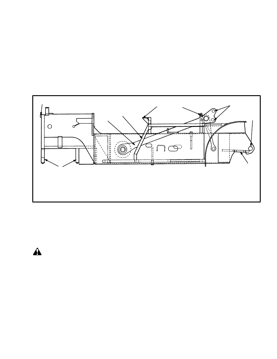
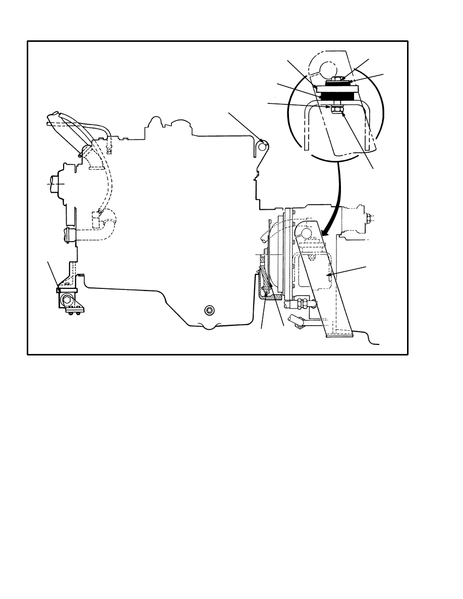
DESCRIPTION (See FIGURE 1.)
The frame is a one piece weldment and has mounts for
the counterweight and fenders, engine, transmission,
axles, hydraulic and fuel tanks, operator’s compartment
and other parts.
FIGURE 1. FRAME
1. COUNTERWEIGHT MOUNT
2. TENSION BAR
3. LADDER
4. OPERATOR COMPARTMENT MOUNT
12720
1
2
3
4
4
5
6
7
8
5. TILT CYLINDER MOUNT
6. MAST MOUNT
7. DRIVE AXLE MOUNT
8. STEERING AXLE MOUNT
REPAIRS
COUNTERWEIGHT
WARNING
The counterweight is very heavy. Make sure that the
lifting devices and lift truck have the capacity to lift
7 000 kg (15 450 lb).
Make sure no one gets under the parts being moved.
Removal (See FIGURE 2.)
1. Remove the ballast cover from the frame.
2. Put the forks of another lift truck under the counter-
weight. Fasten a nylon lifting sling around the counter-
weight and attach the sling to the carriage or load back-
rest of the lift truck.
3. Remove the two bolts that hold the counterweight to
the frame. Raise the counterweight approximately 150
mm (six inches). Carefully remove the counterweight
from the frame and lower it to the floor.
Installation (See FIGURE 2.)
1. Put the forks of a lift truck under the counterweight.
Fasten a nylon lifting sling around the counterweight
and attach the sling to the carriage or load backrest of the
lift truck.
2. Install the counterweight on the frame. Install the
bolts, washers and nuts. Tighten the nuts to 814 N.m
(600 lbf ft).
2
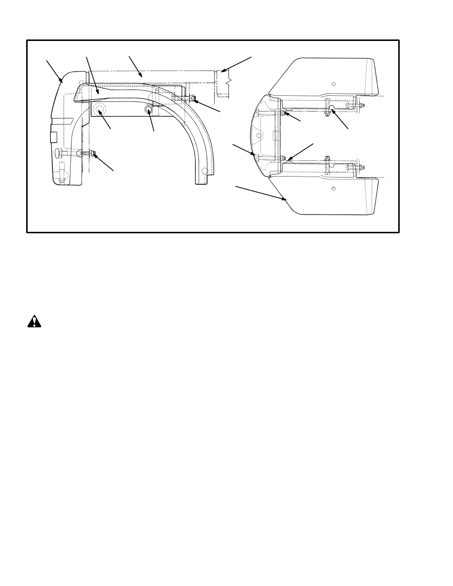
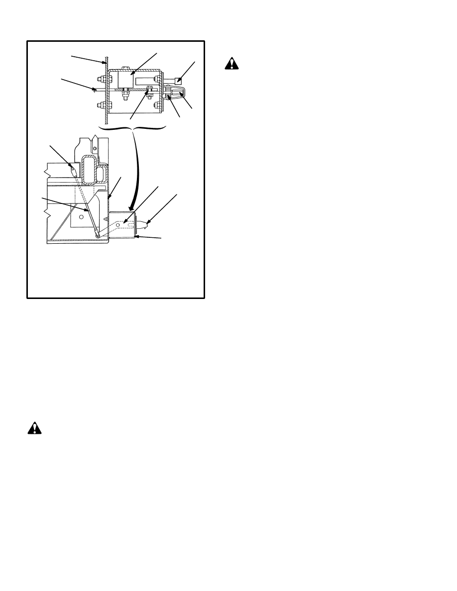
FIGURE 2. COUNTERWEIGHT MOUNTS
1. COUNTERWEIGHT
2. FENDER
3. FENDER DOWEL
4. NUT AND BOLT
5. BALLAST COVER
6. HOOD
7. SLOT
1
2
3
4
4
4
6
5
3
4
2
1
12403
7
FENDERS
Removal (See FIGURE 2.)
WARNING
The fenders are part of the lift truck counterweight
system and are very heavy. Make sure any lifting de-
vices have the capacity to lift 1750 kg (3860 lb).
1. Remove the ballast cover from the frame.
2. Fasten a chain or cable around the middle of the fend-
er. Put the chain or cable through the slot (7) in the fend-
er.
3. Operate the lifting device just enough to give support
to the fender. Remove the nuts, washers and bolts that
hold the fender to the frame.
4. Carefully lift the fender away from the frame and
lower it to the floor.
Installation (See FIGURE 2.)
1. Fasten a chain or cable around the middle of the fend-
er. Make sure the chain or cable is in the slot (7) on the
side of the fender.
2. Raise the fender to the lift truck. Align the tapered
dowels (3) of the fender with the holes in the frame. Do
not disconnect the chain sling.
3. Install the bolts, washers and nuts. Tighten the nuts to
814 N.m (600 lbf ft).
HOOD (See FIGURE 3.)
The hood can be removed from the frame. Disconnect
the exhaust system at the flexible tube connection. (See
FIGURE 8.) Disconnect the air filter at the rubber elbow
connection and the hose from the air restriction indica-
tor. (See FIGURE 7.)
To remove the hood, remove the three nuts and
capscrews at the front and the three nuts and capscrews
at the rear of the hood assembly. Lift the hood from the
frame.
During installation, align the hood as necessary. Make
sure the clamps for the air intake tubes are tight. Air
leaks can cause engine damage.
To remove the ballast cover, remove the four capscrews
that hold it to the frame. Lift the cover away from the
frame.
3
FIGURE 3. HOOD ASSEMBLY
4. AIR FILTER CONNECTION
5. HOOD LATCH
6. HANDLE
7. LATCH FOR TILT CAB
8. GAS SPRING
1
1
3
4
5
6
7
1. BALLAST COVER
2. HOOD
3. EXHAUST COVER
8
12730
HYDRAULIC TANK
The hydraulic tank is installed on the right side of the lift
truck frame.
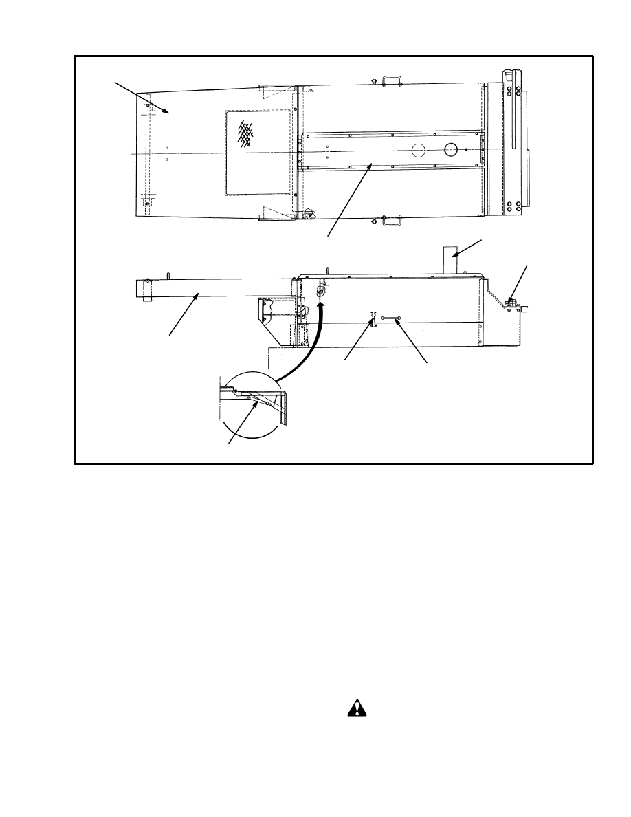
Removal (See FIGURE 4.)
1. Lower the mast completely. Disconnect the three re-
turn lines at the side of the hydraulic tank. Put caps on
the open lines.
2. Put a drain pan under the tank and remove the plug to
drain the tank. (The hydraulic tank holds 325 litres/ 86
gallons of oil.) Disconnect the two supply lines to the
hydraulic pumps. Put caps on the open lines.
3. Remove the three capscrews that hold the base of the
hydraulic tank to the frame. Remove the access door
from the hinges on the tank.
4. Carefully pull the hydraulic tank from the side of the
lift truck. Remove the top of the hydraulic filter(s) if
necessary for clearance.
5. Remove the filter assemblies from the tank. Remove
the back–pressure valve from the tank. Remove the cov-
er and breathers from the top of the tank.
Repairs
SMALL LEAKS
Use the following procedures to repair small leaks:
1. Use steam to clean the area around the leak. Remove
all paint and dirt around the leak.
WARNING
Do not use tools that can make sparks, heat or static
electricity. The vapors in the tank can cause an ex-
plosion.
4
FIGURE 4. HYDRAULIC TANK
1. FILTER ASSEMBLY
2. BACK PRESSURE VALVE
3. RETURN LINE
4. SUPPLY TO TANDEM PUMP
5. SUPPLY TO SINGLE PUMP
6. RETURN LINE FROM BRAKE SYSTEM
7. COVER PLATE
12741
1
2
3
4
5
6
7
2. Apply Loctite 290 to the leak. Follow the instructions
of the manufacturer.
LARGE LEAKS
1. Use one of the procedures described under Cleaning
to clean and prepare the tank for repairs.
2. Use acceptable welding practices to repair the tank.
See the American National Standard Safety in Welding
and Cutting ANSI Z49.1–1973.
Cleaning
WARNING
Special procedures must be followed when large
leaks or other repairs need welding or cutting. All
work must be done by authorized personnel. If the
tank is cleaned inside of a building, make sure there
is enough ventilation. See the following manuals for
additional information:
. “Safe Practices For Welding And Cutting Contain-
ers That Have Held Combustibles” by the American
Welding Society, A6.0–65.
. “Safety In Welding and Cutting”, American Na-
tional Standard, ANSI Z 49.1 – 1973.
When cleaning the tank, do not use solutions that make
dangerous gases at normal temperatures or when
heated. Wear device for the protection of the eyes. Pro-
tect the body from burns.
When cleaning with steam, use a hose with a minimum
diameter of 19 mm (0.75 inch). Control the pressure of
the steam by a valve installed at the nozzle of the hose. If
a metal nozzle is used, it must be made of a material that
does not make sparks. Make an electrical connection be-
tween the nozzle and the tank. Connect a ground wire to
the tank to prevent static electricity.
Steam Method of Cleaning
Use the following procedure to clean the tank with
steam:
1. Remove all the parts from the tank. Install the drain
plug.
2. Fill the tank 1/4 full with a solution of water and so-
dium bicarbonate or sodium carbonate. Mix 0.5 kg (1 lb)
per 4 litres (1 gal) of water.
3. Mix the solution in the tank using compressed air.
Make sure all the surfaces on the inside of the tank are
flushed with the solution. Drain the tank.
4. Put steam into the tank until the tank does not have
odors and the metal is hot. Steam vapors must come
from all the openings.
5. Flush the inside of the tank with boiling water. Make
sure all the loose material is removed from the inside of
the tank.
6. Make an inspection of the inside of the tank. If it is not
clean, repeat steps 4 and 5 and make another inspection.
When making inspections, use light that is approved for
locations with flammable vapors.
7. Put plugs in all the openings in the tank. Wait 15 min-
utes, then remove the inlet and outlet plugs. Test a sam-
ple of the vapor with a special indicator for gas vapors. If
the amount of flammable vapors is above the lower
flammable limit, repeat the cleaning procedures.
5
Chemical Solution Method of Cleaning
If the tank cannot be cleaned with steam, use the follow-
ing procedure:
1. Mix a solution of water and trisodium phosphate or a
cleaning compound with an alkali base. Follow the in-
structions given by the manufacturer.
2. Fill the tank with the cleaning solution. Use com-
pressed air to mix the solution in the tank.
3. Drain the tank. Flush the inside of the tank with hot
(boiling) water. Make sure all the cleaning compound is
removed.
4. Make an inspection of the inside of the tank. If the
tank is not clean, repeat steps 1 to 3. Make another in-
spection of the tank. When making inspections, use a
light that is approved for locations with flammable va-
pors.
5. Check the tank for flammable vapors using special in-
dicator for gas vapors. If the amount of flammable va-
pors is not below the lower flammable limit, repeat the
cleaning procedures.
Other Methods Of Preparation For Repair
If nitrogen gas or carbon dioxide gas is available, pre-
pare the tank for welding using these gases. See the
manual Safe Practices For Welding and Cutting Con-
tainers That Have Held Combustibles by the American
Welding Society, A6.0–65. If these gases are not avail-
able, another method using water can be used as fol-
lows:
1. Fill the tank with water to just below the point where
the work will be done. Make sure the space above the
level of the water has a vent.
2. Use acceptable welding practices to repair the tank.
See the American National Standard Safety In Welding
And Cutting ANSI Z 49.1–1973.
Installation
1. Use a lifting device to move the hydraulic tank next to
the frame. Push the hydraulic tank into position in the
frame. Install the three capscrews and washers that hold
the hydraulic tank to the frame.
2. Connect the three return lines to the tank.
3. Install the back–pressure valve and adapter in the
tank. Connect the two supply lines for the pumps to the
fittings on the tank.
4. Install the hydraulic filter assemblies in the tank. In-
stall the cover and breathers on top of the tank. Install the
access door on the hinges of the tank.
5. Fill the hydraulic tank to the correct level with the oil
specified in the maintenance table. See the section PE-
RIODIC MAINTENANCE, 8000 SRM 487.
FUEL TANK
The fuel tank is installed between the frame rails, behind
the mast.
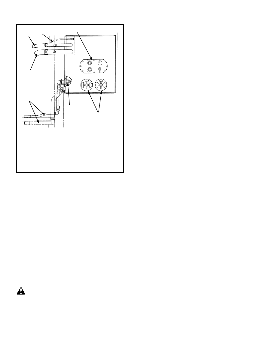
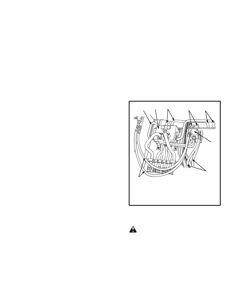
FIGURE 5. CONNECTIONS AT THE
MANIFOLD BLOCKS
1. HYDRAULIC MANIFOLD BLOCK
2. TILT CYLINDER MANIFOLD
3. LINES TO LIFT CYLINDERS
4. LINES TO TILT CYLINDERS
5. LINES TO BRAKE SYSTEM
1
2
3
5
4
3
3
4
12738
Removal (See FIGURE 5.)
WARNING
If the fuel is drained from the fuel tank, put the fuel
in a can or barrel that has a sealed cap.
1. Lower the mast completely. Put a drain pan under the
fuel tank. Remove the drain plug to drain the fuel from
the tank. Disconnect the fuel lines at the tank. Put caps
on the open lines.
2. Disconnect and remove the hydraulic lines to the
manifold blocks for the lift cylinders and tilt cylinders.

6
Put tags for identification on the lines. Put caps on the
open lines. Remove the manifold blocks from the tank.
3. Disconnect and remove the brake lines that are on top
of the fuel tank. Put tags for identification on the lines.
Put caps on the open lines.
4. Remove the capscrews that hold the filler tube to the
tank. Loosen the filler tube from the tank.
5. Connect a lifting device to the tank. Remove the four
capscrews that hold the tank to the frame. Lift the tank
from the frame.
Repairs
Repair the fuel tank as described in the repair proce-
dures for the hydraulic tank.
WARNING
Do not use tools that can make sparks, heat or static
electricity. The vapors in the tank can cause an ex-
plosion.
Installation (See FIGURE 5.)
1. Put the tank in position on the frame. Install the cap-
screws to hold the tank to the frame.
2. Use a new gasket and install the filler tube on the tank.
3. Connect the fuel lines to the tank and filler tube.
4. Install the manifold blocks for the lift and tilt cylin-
ders on the top of the fuel tank. Connect the lines to the
manifold blocks.
5. Install and connect the brake lines that fit over the fuel
tank.
RADIATOR
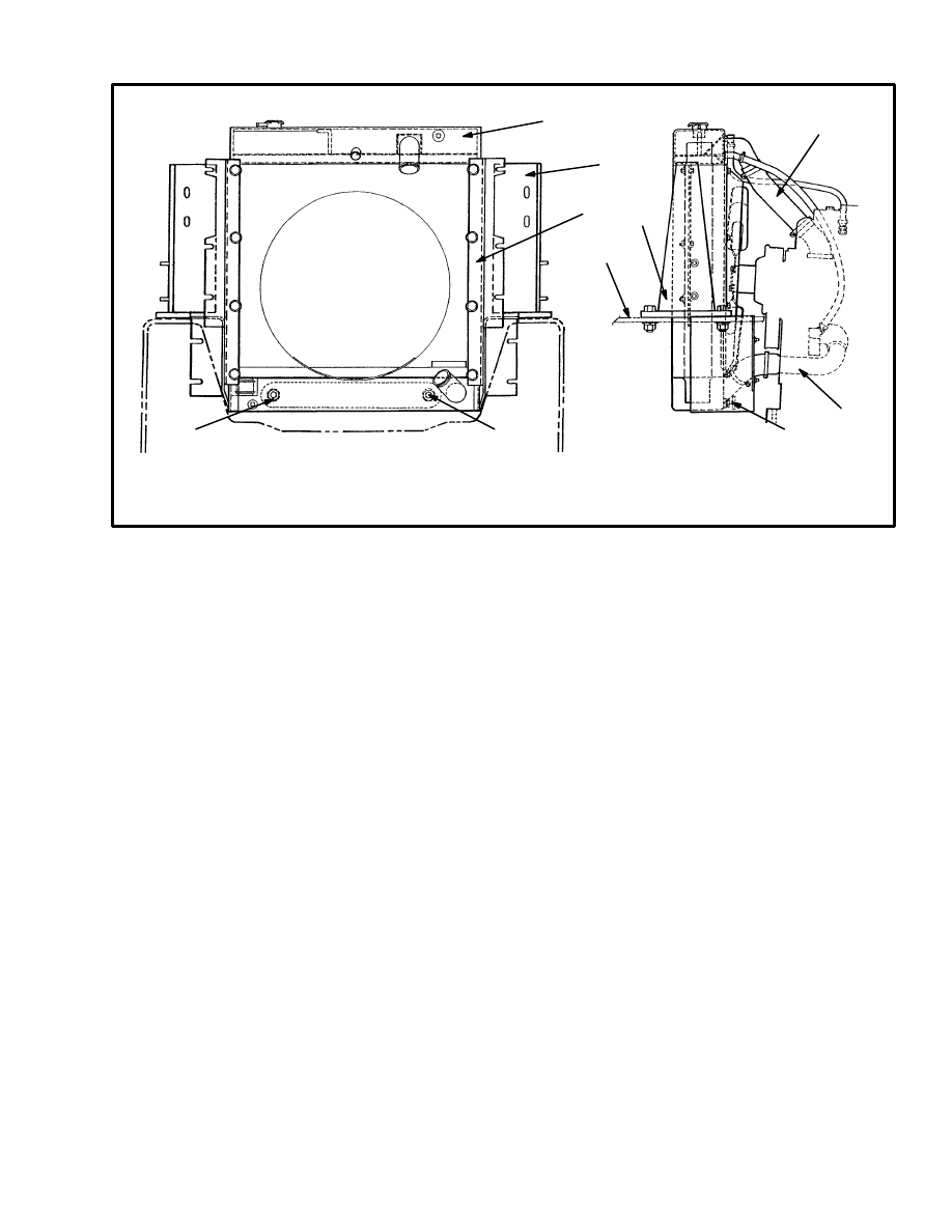
Removal (See FIGURE 6.)
1. Remove the ballast cover.
2. Disconnect the air filter intake elbow and air restric-
tion indicator hose from under the center hood panel.
Disconnect the exhaust system between the muffler ex-
haust pipe and the exhaust swivel connection. Remove
the hood assembly. Remove the ballast cover.
3. Remove the fan from the engine.
4. Disconnect the transmission oil lines at the bottom of
the radiator. Disconnect the coolant hoses at the radiator.
5. Remove the bracket for the transmission oil filter at
the radiator bracket.
6. Remove the bolts that hold the radiator bracket to the
frame. Remove the radiator and bracket. Remove the ra-
diator from the brackets.
Installation (See FIGURE 6.)
1. Install the brackets on the radiator. Install the radiator
and brackets in the frame. Install the bolts for the brack-
ets.
7
FIGURE 6. RADIATOR
4. PORTS FOR TRANSMISSION
OIL COOLER
5. TOP HOSE
1
2
2
3
4
4
6
5
7
8
12725
1. RADIATOR
2. BRACKET
3. RADIATOR MOUNT
6. FRAME OF LIFT TRUCK
7. BOTTOM HOSE
8. DRAIN VALVE
2. Install the fan on the engine.
3. Connect the coolant hoses to the radiator. Connect the
transmission oil lines to the bottom of the radiator.
4. Attach a lifting device and sling and install the hood
assembly. Align the hood as necessary. Install the rubber
elbow to the pre–cleaner tube and small hose to the air
restriction indicator connections under the center hood
panel. Make sure the clamps for the air intake tubes are
tight. Air leaks can cause engine damage. Connect the
muffler to the exhaust pipe at the flexible tube connec-
tion. Install the ballast cover.
5. Fill the cooling system with coolant after the engine
installation is complete. See the section PERIODIC
MAINTENANCE, 8000 SRM 487.
ENGINE
Removal (See FIGURE 9.)
NOTE: The engine can be removed with or without the
transmission. The following procedures are for the re-
moval of the engine only.
1. Disconnect the cables at the battery. (Remove the
ground cable first.)
2. Disconnect the air filter intake elbow and air restric-
tion indicator hose from under the center hood panel.
Disconnect the exhaust system at the flexible tube con-
nection. (See FIGURE 8.) Remove the hood assembly.
3. Drain the coolant from the cooling system. Discon-
nect the hoses at the radiator. Remove the radiator. (See
FIGURE 6.)
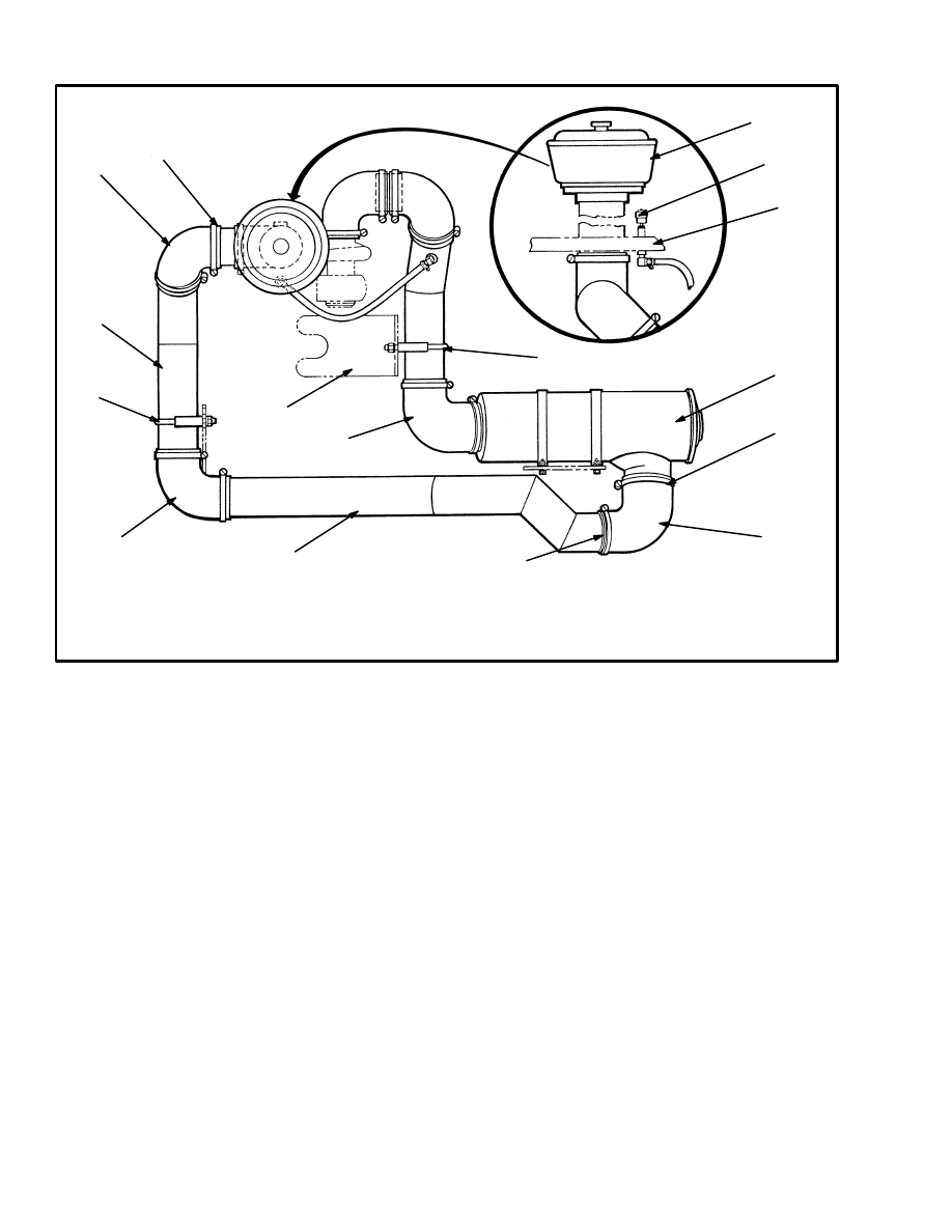
4. Remove the tubes between the engine and air filter.
(See FIGURE 7.)
5. Disconnect the exhaust system. Remove the pipe at
the turbocharger.
6. Disconnect fuel lines at the fuel injection pump and
the fuel pump. Disconnect the throttle linkage.
8
6. BRACKET
7. HOSE
8. PRE–CLEANER
9. AIR RESTRICTION INDICATOR
10. HOOD
FIGURE 7. AIR FILTER ARRANGEMENT
1. AIR FILTER
2. HOSE CLAMP
3. RUBBER ELBOW
4. TUBE
5. CLAMP
1
2
3
4
3
5
4
3
2
2
6
3
8
9
10
5
12723
9
12722
FIGURE 8. EXHAUST SYSTEM
1. EXHAUST STACK
2. RAIN CAP
3. CLAMP
4. EXHAUST COVER
5. MUFFLER
2
3
3
4
5
6
7
8
3
6. TURBOCHARGER
7. EXHAUST TUBE
8. BRACKET
9. FLEXIBLE TUBE
10. CLAMP
9
10
1
7. Disconnect wires and wiring harnesses at the engine.
Disconnect the heater hoses at the engine.
8. Disconnect the transmission dipstick tube from the
engine.
9. Connect a lifting device to the engine. Make sure the
lifting device has a capacity of at least 680 kg (1500 lb)
(engine only).
10. Remove the plug in the flywheel housing. Remove
the capscrews that hold the drive plate to the flywheel.
Remove the capscrews that hold the torque converter
housing to the flywheel housing.
11. Remove the capscrews that hold the mount at the fan
end of the engine to the frame.
12. Carefully lift the engine from the frame. Make sure
all the connections have been removed. Make sure the
torque converter stays with the engine and does not fall.
Installation (See FIGURE 9.)
1. Connect a lifting device to the engine. Make sure the
lifting device has a capacity of at least 680 kg (1500 lb).
2. Lubricate the pilot bushing in the flywheel with mul-
ti–purpose grease. Make sure the torque converter stays
in the transmission. Install the engine to the transmis-
sion, making sure the flywheel is aligned with the torque
converter. Install the capscrews that hold the torque con-
verter housing to the flywheel housing.
3. Install the bolt for the front engine mount. Remove the
lifting device.
4. Install the capscrews and washers that hold the drive
plate to the flywheel. Tighten the capscrews to 36 N.m
(26 lbf ft). Install the plug in the flywheel housing.
5. Install the radiator. Connect the coolant hoses and
transmission oil lines to the radiator. Connect the oil line
at the top of the torque converter.
6. Connect the heater hoses, wiring harnesses, wires and
throttle linkage to the engine. Connect the transmission
dipstick tube to the engine.
7. Connect the fuel lines at the fuel injection pump and
the fuel pump.
10
12728
1. ENGINE MOUNT
2. LIFTING EYE
3. ENGINE FLYWHEEL
4. DRIVE PLATE
5. TRANSMISSION MOUNT
1
5
6. BOLT
7. WASHER
8. RUBBER MOUNT
9. MOUNT BRACKET
10. WASHER
11. NUT
2
3
4
6
7
9
8
10
11
FIGURE 9. ENGINE INSTALLATION
8. Install the air filter and connecting tubes. Make sure
the clamps for the air intake tubes are tight. Air leaks can
cause engine damage.
9. Attach a lifting device and sling and install the hood
assembly. Install the rubber elbow to the pre–cleaner
tube and the small hose to the air restriction indicator.
Connect the muffler to the exhaust system at the flexible
tube connection.
10. Connect the battery cables to the battery. Fill cooling
system with coolant. Check all oil levels. Start the en-
gine and check for leaks and correct operation.
OPERATOR COMPARTMENT AND CAB
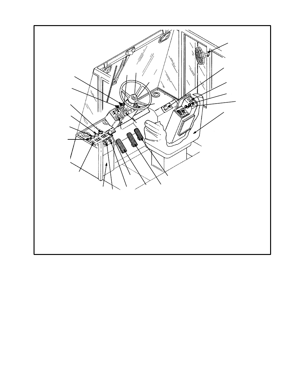
General (See FIGURE 10.)
The operator compartment includes the hydraulic con-
trol levers, steering wheel, instrument panel, transmis-
sion and brake system controls, attachment controls and
the seat. The overhead guard is built into the operator
compartment. The cab has doors, windows, window
wipers, fan and a heater system.
The operator compartment is installed on a platform and
support base above the main frames members. On lift
trucks with the tilt cab, the support platform is hinged
and can tilt forward, toward the mast. Stairways and
steps on both sides of the lift truck give access to the op-
erator platform.
The operator compartment can be installed in the center
of the frame or to the left side of the lift truck.The opera-
tor compartment is a separate module from the frame of
the lift truck and can be removed as a complete unit. On
lift trucks with the tilt cab, the operator compartment
can be removed with or without the support platform.
11
6. PARKING BRAKE
INDICATOR LIGHT
7. FUSE PANEL
8. SWITCHES,
LEFT TO RIGHT:
OPTIONAL
REAR WIPER
TOP WIPER
FRONT WIPER
LIGHT
LIGHT
LIGHT
1
2
3
4
5
6
7
8
9
10
11
12
13
14
1. ACCELERATOR PEDAL
2. BRAKE PEDAL
3. INCHING/BRAKE PEDAL
4. PARKING BRAKE KNOB
5. LOW BRAKE PRESSURE
INDICATOR LIGHT
15
16
17
18
19
20
21
22
23
24
25
26
17. HOUR METER
18. FUEL GAUGE
19. KEY SWITCH
20. WARNING INDICATORS:
ALTERNATOR
ENGINE OIL PRESSURE
TRANS. OIL PRESSURE
TRANS. OIL TEMP.
21. FAN
22. HEATER CONTROLS
23. ATTACHMENT CONTROLS
24. TILT CONTROL LEVER
25. LIFT/LOWER CONTROL LEVER
26. SEAT
9. TRANS. OIL TEMP. GAUGE
10. TRANS. OIL PRESS. GAUGE
11. VOLTMETER
12. ENGINE OIL PRESS. GAUGE
13. TWIST LOCK CONTROL
14. COOLANT TEMP. GAUGE
15. RANGE LEVER
16. DIRECTION LEVER
FIGURE 10. OPERATOR COMPARTMENT AND CAB
Removal
(See FIGURE 11. and FIGURE 22.)
NOTE: If the operator compartment/cab needs repair or
replacement, remove it using the following procedures.
1. Remove the doors from the cab. Remove the cap-
screws for the floor plates. Remove the center floor plate
and seat.
2. Remove the panel from the hydraulic control console.
Put tags for identification on the hydraulic lines. Dis-
connect the hydraulic lines at the control valves. Dis-
connect the wiring harness at the switches. Remove the
floor plate and console.
3. Put tags for identification on the hydraulic lines. Dis-
connect the hydraulic lines at the steering control unit.
4. Disconnect the hydraulic lines at the parking brake
valve. Disconnect the hydraulic lines at the brake pedal
valves or move the floor plate and pedals out of the way.
If necessary, disconnect the throttle cable at the acceler-
ator pedal.
12
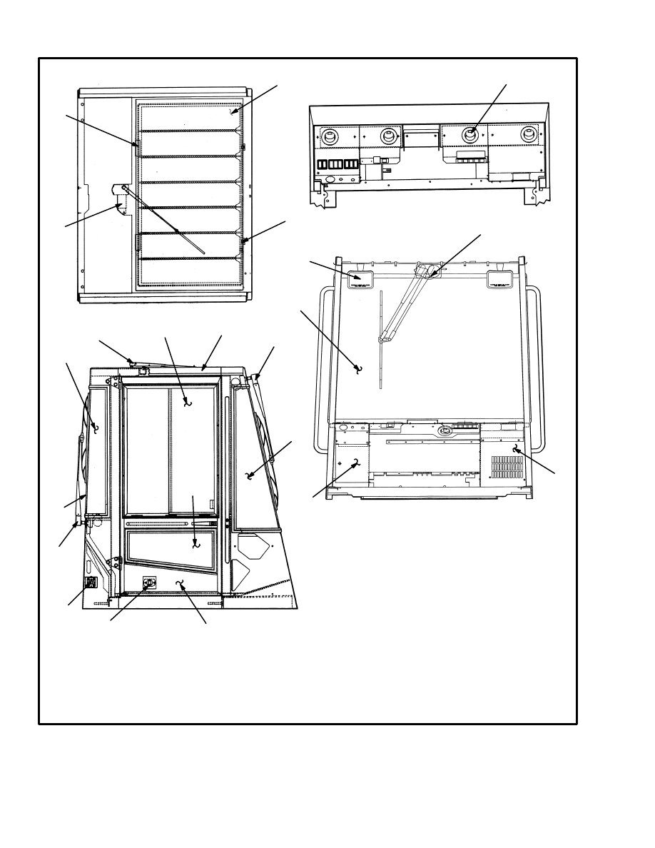
1. WINDOW RETAINER
2. TOP WINDOW
3. WINDOW CLAMP
4. TOP WIPER MOTOR
5. DEFROSTER VENT
6. TOP WIPER ARM
1
2
3
4
5
6
8
7
9
10
11
12
13
14
15
16
17
18
19
20
21
22
7. SIDE WINDOW
8. CAB FRAME
9. FRONT WIPER ARM
10. FRONT QUARTER WINDOW
11. LOWER DOOR WINDOW
12. REAR QUARTER WINDOW
13. REAR WINDOW
14. REAR WIPER
15. DOOR RETAINER LATCH
16. DOOR RETAINER
17. DOOR
18. AIR VENT
19. FUSE PANEL
20. FRONT WINDOW
21. MIRROR
22. FRONT WIPER MOTOR
12507
FIGURE 11. OPERATOR COMPARTMENT AND CAB ASSEMBLY
5. Disconnect the wiring from the fuse panel at the en-
gine, transmission and other components.
6. Disconnect the hoses at the heater core and the heater
valve. Disconnect the wiring harness at the heater.
13
7. Remove the bolts and nuts that hold the operator com-
partment to the frame mounts. For tilt cabs, remove the
bolts and nuts between the operator compartment and
the cab platform.
WARNING
Make sure that the lifting device has the capacity to
lift a minimum of 454 kg (1000 lb).
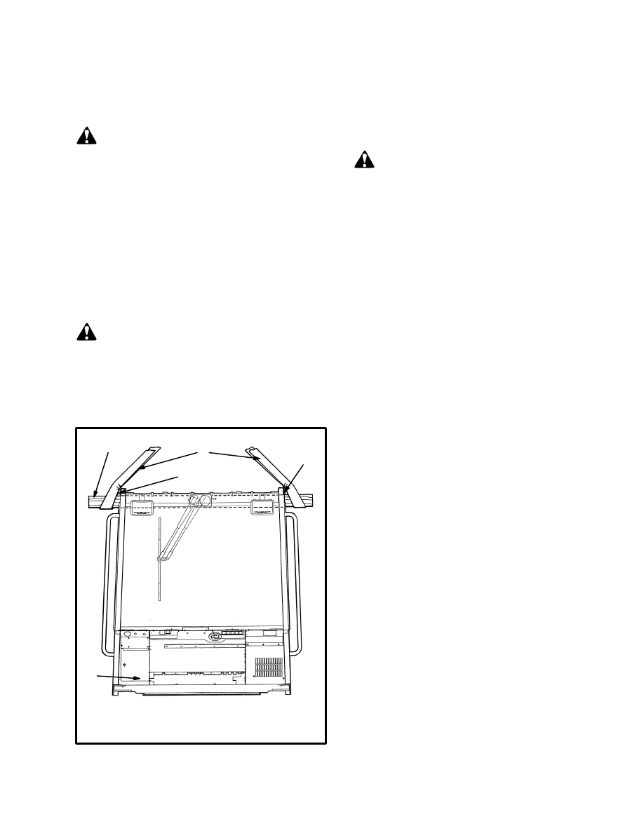
8. See FIGURE 12. Connect a lifting device to a
spreader bar that is through the door openings at the top
of the operator compartment (under the overhead guard
structure). Put material that will be a cushion at the top
of the door openings to prevent damage. Carefully lift
the cab away from the lift truck. Set the cab assembly in
a storage area and put blocks under the unit to give it sta-
bility.
CAUTION
Make sure all hydraulic lines, brake lines, electrical
wires and other hoses and attachments are not dam-
aged.
1. SPREADER BAR
2. SLING
2
3
12468
FIGURE 12. MOVE THE CAB
1
4
4
3. CAB
4. CUSHION
Installation
(See FIGURE 11. and FIGURE 22.)
NOTE: If the operator compartment/cab was removed
for repair or replacement, install it using the following
procedures.
WARNING
Make sure that the lifting device has the capacity to
lift a minimum of 454 kg (1000 lb).
1. See FIGURE 12. Connect a lifting device to a
spreader bar that is through the door openings at the top
of the operator compartment (under the overhead guard
tubes). Put material that will be a cushion at the top of
the door openings to prevent damage. Install the opera-
tor compartment on the mounts. Install the rubber
mounts, washers, nuts and bolts for the mounts.
2. Connect the hydraulic lines to the steering control
unit.
3. Install the floor plate with the brake pedals. If neces-
sary, connect the hydraulic lines. Connect the throttle
cable. Connect the hydraulic lines to the parking brake
valve.
4. Connect the hydraulic lines for the control valves at
the hydraulic console. Make sure the lines are connected
to the correct ports.
5. Connect the wiring and wires at the fuse panel and
other components in the operator compartment.
6. Connect the hoses at the heater core and the heater
valve.
7. Install the floor plates and the seat.
8. Install the doors.
9. Operate the brakes, steering and hydraulic system and
check for leaks and correct operation.
Repairs
GAUGES AND SWITCHES
1. The gauges and switches on the cowl are fastened to
removable panels. Disconnect the wiring harnesses and
remove the screws that hold the panels to the instrument
panel. The electrical wiring diagrams are in the section
DIAGRAMS, 8000 SRM 488. These diagrams will
help identify the wiring harnesses and components.
14
2. See the section INSTRUMENT PANEL INDICA-
TORS AND SENDERS, 2200 SRM 143 to replace the
gauges
3. The rocker switches are replaced by pressing in on the
flexible tabs at the back side to release the switch assem-
bly from the instrument panel. The replacement switch
is installed from the top side of the instrument panel and
pressed in until the tabs on the switch lock in the opening
for the switch.
1. THREADED TUBE
2. MOTOR
3. GEAR ASSEMBLY
4. WIRE HARNESS
1
2
3
2
1
3
4
12510
FIGURE 13. WINDOW WIPERS
4. Remove the remote control valves as described in the
section THE HYDRAULIC SYSTEM, 1900 SRM
492.
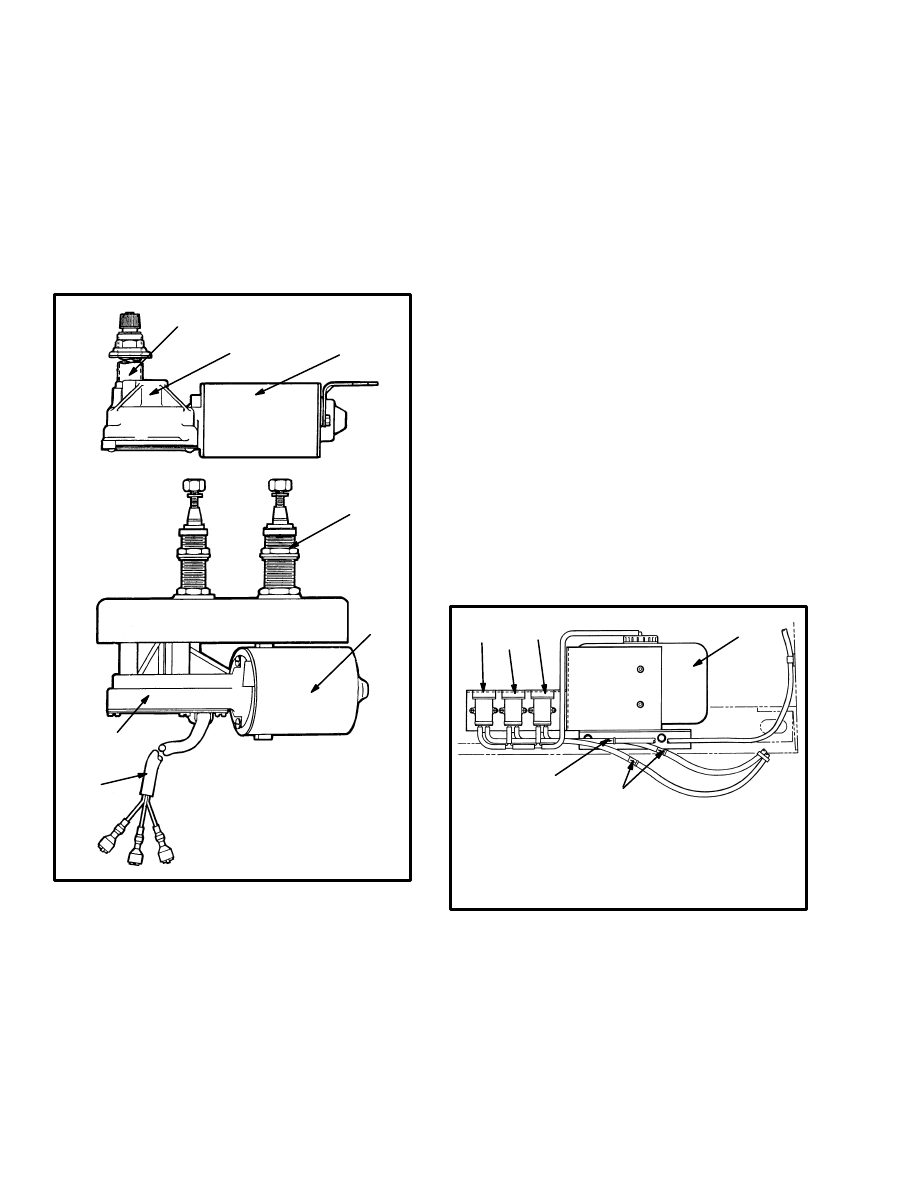
WINDOW WIPERS (See FIGURE 13.)
Three window wiper motor assemblies are installed in
the operator compartment. The front window motor as-
sembly has two wiper arms connected to a single wiper
blade. The rear window and the top (overhead) window
have wiper motor assemblies that have one wiper arm
attached to a single wiper blade.
Replace the single arm unit as follows:
a. To replace this motor assembly, first remove the
arm (or arms) and the blade from the outside. Re-
move the nut and washers from the threaded shaft
tube that passes through the metal frame of the
operator compartment.
b. Remove the one mount screw from the single arm
wiper motor, disconnect the electrical wire and
remove from the operator compartment.
c. When you install the wiper motor be sure to con-
nect the electrical wires first.
Replace the double arm unit as follows:
a. To replace this motor assembly, first remove the
arms and the blade from the outside. Remove the
nuts and washers from the two threaded shaft
tubes that passes through the metal frame of the
operator compartment.
b. Disconnect the electrical wires and remove the
wiper motor from the front window.
FIGURE 14. WINDOW WASHERS
1. FRONT WASHER MOTOR/PUMP
2. TOP WASHER MOTOR/PUMP
3. REAR WASHER MOTOR/PUMP
4. CHECK VALVE
5. RESERVOIR
1
2
3
5
4
4
12743
Window Washer Motor/Pumps
(See FIGURE 14.)
Three window washer motor/pump assemblies, and a
water reservoir are installed just below and at the right
rear part of the operator compartment. When cleaning or
replacing any of the hoses, make sure the check valves
are installed so that the arrows are toward the nozzles.
15
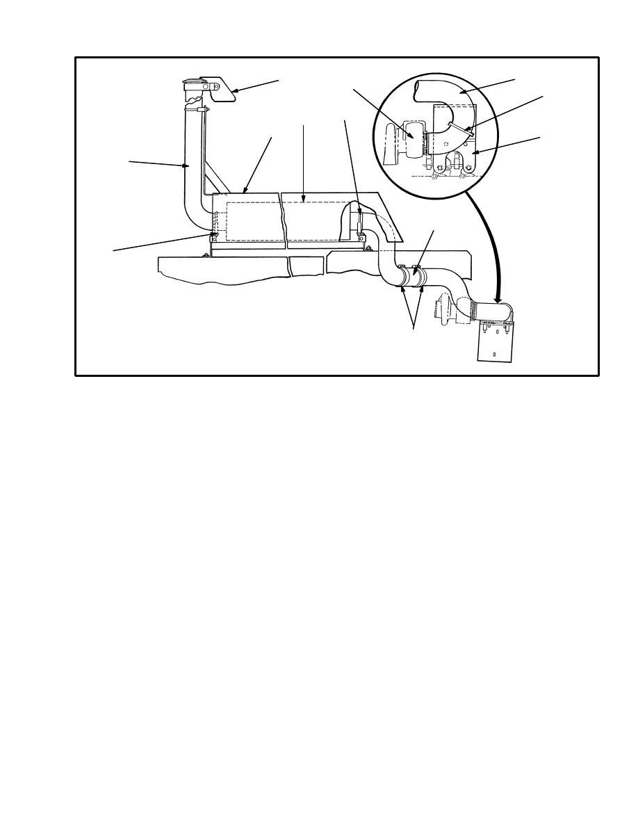
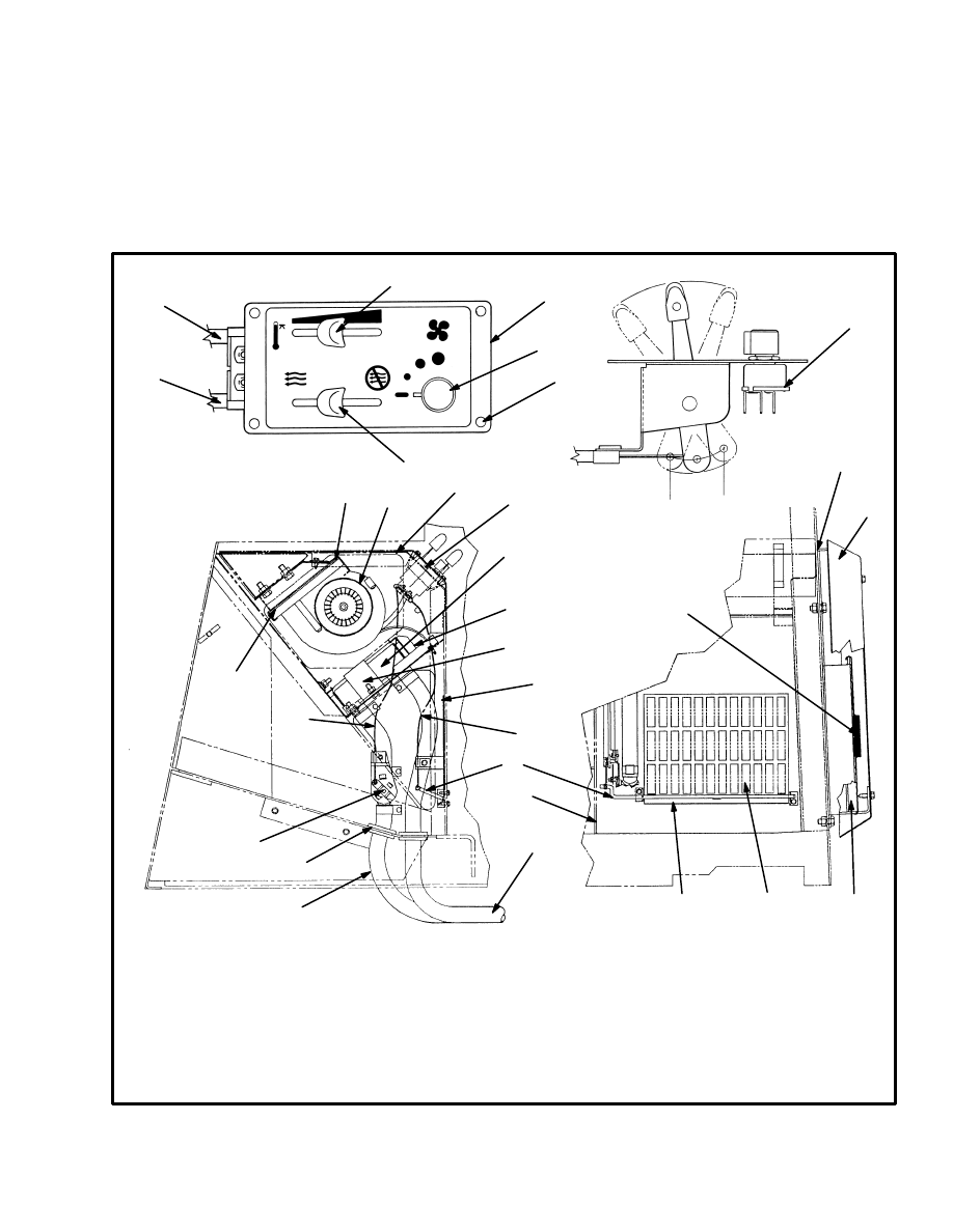
Heater Assembly
REMOVAL (See FIGURE 15.)
Heater Control Panel Assembly:
1. Remove the right–hand access panel (22) and discon-
nect the control cables from the damper rod (10) and the
heater valve (14).
2. Remove the four screws (26) from the face plate (4).
Disconnect the blower electrical harness from the
blower control switch (23) and remove the heater con-
trol panel (4) and cable assemblies (9 and 15).
1. RETAINER
2. BLOWER ASSEMBLY
3. COVER
4. CONTROL ASSEMBLY
5. HEATER CORE
6. SUPPORT PLATE
7. CLAMP
8. DAMPER PLATE
9. DAMPER CONTROL CABLE
10. DAMPER ROD
11. HEATER HOSE (RETURN)
12. HEATER HOSE (SUPPLY)
13. HOSE GROMMET
14. HEATER VALVE
15. HEAT CONTROL CABLE
16. BLOWER GASKET
17. ADHESIVE SEALANT
18. INTAKE COVER
9
15
24
4
23
26
25
23
1
2
3
4
16
12
13
14
5
6
7
11
10
9
8
19. SPRING
20. FILTER
21. VENTS
22. ACCESS PANEL, RH
23. BLOWER CONTROL SW.
24. HEAT CONTROL LEVER
25. DAMPER CONTROL LEVER
26. SCREW (4)
22
21
20
8
19
18
17
12511
12384
FIGURE 15. HEATER SYSTEM
15
16
Blower and Core Assemblies:
1. Remove the right–hand access panel (22) and discon-
nect the control cables from the damper rod (10) and the
heater valve (14).
2. Remove the sheet metal screws and the cover panel
(3) from the cowl. Disconnect the blower electrical har-
ness from the blower control switch (23) as the cover
panel is removed.
3. Disconnect the blower harness from the electrical
harness and disconnect the ground wire. Remove the
two screws that fasten the blower retainer over the base
of the blower assembly (at the top). Pivot the blower as-
sembly downward and then position the assembly so
that is can be lifted out of the cowl area.
4. The heater core can be removed by disconnecting the
heater hoses (through the right–hand access panel). Re-
move the capscrews and clamp (7) that fasten the core to
the support panel. Remove the heater core.
INSTALLATION
See FIGURE 15. Install the heater assembly in the re-
verse order of removal.
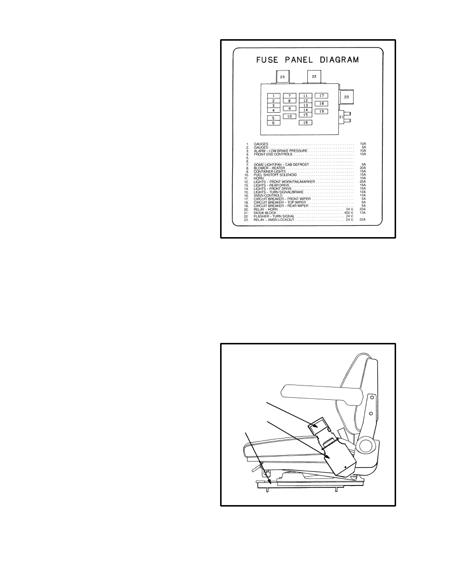
Fuse Panel (See FIGURE 16.)
The fuse panel with the fuses for the window wipers,
lights, fan and heater system is inside the operator com-
partment. This fuse panel is behind a door at the front of
the left instrument console.
The fuse panel can be pulled away or removed from the
mount by loosening two capscrews, then sliding the
panel upward and out. See the section DIAGRAMS,
8000 SRM 488 for the electrical wiring of the operator
compartment.
12384
FIGURE 16. FUSE PANEL
Operator Restraint System
(See FIGURE 17. and FIGURE 18.)
The seat belt, seat and mounting are all part of the opera-
tor restraint system. Each part must be inspected to
make sure the attachment points are fastened correctly
and that the part operates correctly and is in good condi-
tion.
FIGURE 17. CHECK THE SEAT
11157
1. SEAT BELT RETRACTOR
2. SEAT BELT LATCH
3. SEAT RAIL
2
3
1
The seat belt must fasten correctly. Make sure the seat
belt can be pulled from the retractor and retracts
17
smoothly and is not worn or damaged. If the seat belt can
not be pulled from the retractor assembly, remove the
screw that keeps the cover on the retractor assembly.
Push the bar to release the spool. Straighten the belt so
that it pulls out and retracts smoothly. The seat belt must
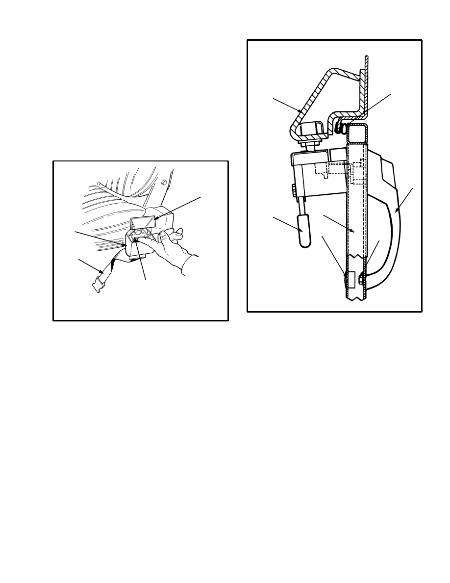
latch securely. (See FIGURE 18.)
Make sure the seat rails are fastened correctly at the at-
tachment points. The seat must lock in position on the
seat rails, but the seat must slide freely when it it un-
locked.
1. COVER OPEN
2. SEAT BELT RETRACTOR
11806
3. SEAT BELT
4. BAR
FIGURE 18. RELEASE A JAMMED SEAT BELT
1
2
3
4
Door Handle Assembly (See FIGURE 19.)
The door handle assemblies are made up of three com-
ponents; an outside handle with lock, an inside lever
type handle and latch mechanism and a striker.
The outside door handle is fastened to the door by a
capscrew and washer installed through an access hole
from the inside of the door. The inside door handle is fas-
tened to the door by two capscrews and washers. This
handle assembly has a latch mechanism that contacts the
striker. The striker is installed on the forward door post
by two capscrews and washers.
4. DOOR
5. INSIDE DOOR
HANDLE
6. CAB FRAME
7. DOOR SEAL
1
2
3
4
5
6
7
1. OUTSIDE DOOR HANDLE
2. CAPSCREW
3. PLUG
12505
FIGURE 19. DOOR HANDLE ASSEMBLY
Door Retainer Assemblies
(See FIGURE 20.)
The door retainer assembly will lock the door in the full
open position. A latch mechanism is mounted behind
the doors on each side of the operator compartment.
This latch contacts the retainer plate on the door when
the door is in the fully open position and is pressed into
the retainer.
A door release handle and link assembly is located just
inside the door at the lower hinge area. This handle and
link assembly will operate a crank inside the bracket on
the outside of the cab. The door (if open and locked in
position) will release when the handle is pulled.
18
1. DOOR RELEASE
2. ROD
3. SIDE OF CAB
4. CRANK
5. DOOR RETAINER
1
3
2
4
5
6
3
4
7
5
8
9
10
6. LATCH
7. SPACER
8. LATCH
9. SPRING
10. SPACER
12505
FIGURE 20. DOOR RETAINER ASSEMBLY
Window Replacement (See FIGURE 21.)
The front, rear and lower door windows can be replaced
as separate units. These windows are held in their open-
ings by a rubber seal. The slider windows and frames in
the doors must be replaced as a complete unit. The top
window is a single piece of material with no frame and is
fastened by clamps and adhesive.
WARNING
All windows installed in the cab are made of special
material, not regular glass. All new windows must
be made of the correct material and thickness as the
windows furnished with the lift truck. See TABLE 1
for correct material for each window.
FRONT AND REAR WINDOWS
The glass in the front and rear window assemblies is
laminated at the connecting edges by silicone sealant.
Use the following procedure to replace the windows.
1. Install the rubber seal in in window opening.
CAUTION
When installing the glass, use glass installation tools
with edges that are not sharp to help avoid breaking
the glass. Use these tools between the glass and the
rubber seal.
2. Install the two side panels of glass into the groove in
the rubber seal. The main panel is installed last.
NOTE: Make sure the glass is dry, clean and free of
grease.
3. Install the spacers (8), one midway vertically at the
edges of the side and main window panels. This proce-
dure will make sure there is even space between the pan-
els before and after the silicone sealant is applied.
4. Install the main glass panel into the groove in the bot-
tom of the rubber seal.
5. When the glass is in the groove, the rubber seal will
initially hold the glass away from the edges of the side
quarter panels. Place the palms of both hands, one at
either side of the window panel and press evenly toward
the operator compartment. The panel will go into place.
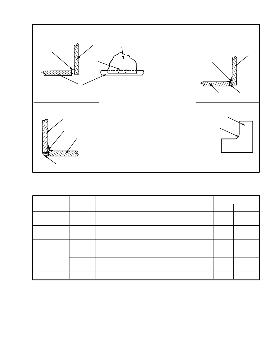
6. Put masking tape on the inside corners where the two
panels of glass come together. Apply the correct amount
of silicone sealant to make a good seal with no holes.
Make a template to fit around the outside corner of the
windows. (See FIGURE 21.). Use the template to re-
move all excess silicone sealant from the window pan-
els.
LOWER DOOR WINDOWS
These windows are installed into the window openings
with the use of the same type rubber seal described for
the front and rear window installations.
UPPER DOOR (SLIDER) WINDOWS
1. Use a hand drill with a 4 mm (5/32 in) bit to remove
the rivets that hold the window frames to the door frame
assembly. Use a chisel and a punch if necessary to com-
pletely remove the rivets.
NOTE: The windows are installed at the factory with a
silicone sealant on all seams and window trim. Remove
all old silicone sealant.
19
USE TAPE AT INSIDE OF CORNER OF
WINDOW DURING APPLICATION OF
SILICONE ADHESIVE. REMOVE TAPE
WHEN DRY.
REAR WINDOW
FRONT WINDOW
IMMEDIATELY REMOVE EXCESS
SILICONE ADHESIVE WITH A TEMPLATE.
RADIUS = 4 mm (0.16 in)
*
**
Cut spacer (PN 3767840) in half. Insert half of the spacer
between the main and quarter glass on each side, mid-
way between top and bottom. Adjust the quarter window
to obtain even space between the two glass panels.
FIGURE 21. REPLACEMENT OF WINDOWS
1. APPLY SILICONE ADHESIVE
2. GLASS MUST BE DRY, CLEAN
AND FREE OF GREASE
3. FRONT WINDOW
4. FRONT QUARTER WINDOW
1
9
5
6
8
3
4
8
3
9
**
1
4
*
3
7
**
*
5. REAR WINDOW
6. REAR QUARTER
WINDOW
7. TEMPLATE
8. SPACER
9. TAPE
12508
TABLE 1. MATERIAL SPECIFICATIONS FOR CAB WINDOWS
THICKNESS
FRONT, MAIN
TINTED LAMINATED SAFETY GLASS
mm
inches
per ANSI Z26.1 AS1 REQUIREMENTS
REAR, MAIN
TINTED LAMINATED or TEMPERED
SAFETY GLASS per ANSI Z26.1 AS2 REQUIREMENTS
DOORS
TINTED TEMPERED SAFETY GLASS
TOP
TINTED LEXAN MR 5004–310351
5.9–7.5
FRONT, QTR.
1301371
1301373
1301372
1301374
1311302
1311303
TINTED LAMINATED or TEMPERED
SAFETY GLASS per ANSI Z26.1 AS2 REQUIREMENTS
REAR, QTR.
UPPER RH
UPPER LH
LOWER, R/L
1301375
5.6–6.8
5.6–6.8
5.6–6.2
3.0
0.12
333908
0.23–0.29
0.22–0.27
0.22–0.25
0.22–0.27
per ANSI Z26.1 AS2 REQUIREMENTS
LOCATION
OF WINDOW
HYSTER
PART NO.
MATERIAL
SPECIFICATION
TOP WINDOW
Remove the two screws and window clamps, then lift
out the window.
Use the silicone sealant on the top of the cross bar on the
overhead assembly. Install the top window under the
two clips at the rear. Lower the window onto the adhe-
sive and fasten it at the front with the two window
clamps and screws.
2. Have a dealer for Hyster lift trucks, or a qualified
glass supplier replace any damaged window or frame
parts. Be sure that the material and the thickness of the
window parts are correct. (See TABLE 1.)
20
3. Align the window frame with the upper opening in the
door frame. Use a drill to make new holes for the fasten-
ers, if new window frames are used. Apply silicone
sealant (Hyster part no. 280472) to the mounting sur-
faces for the window frames. Fasten the window to the
door frame with rivets (or capscrews, washers and lock
nuts).
1. PUMP
2. PORT (RAISE)
3. PORT (LOWER)
1
1
2
3
4
3
2
7
5
6
6
8
13
11
14
15
4
9
9
8
10
16
5
11
10
13
10
12
14
11
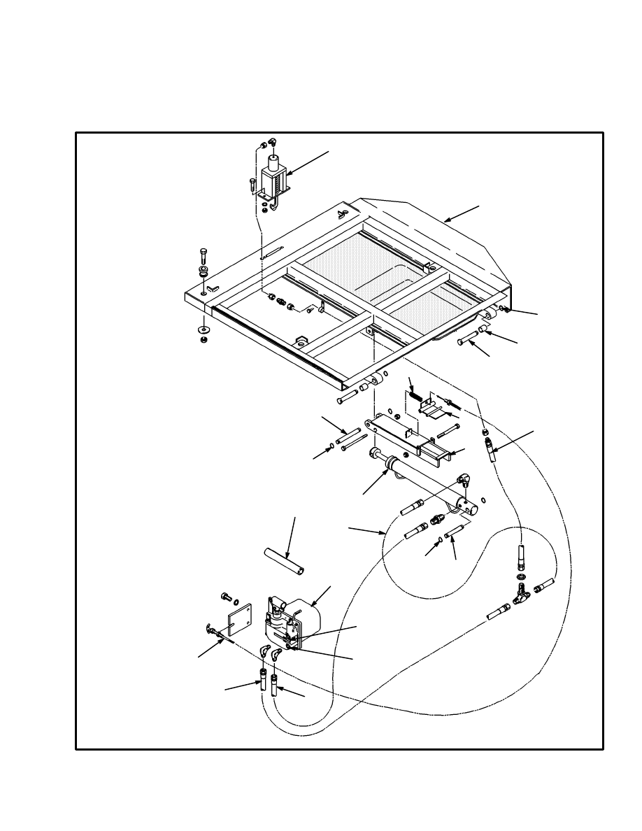
FIGURE 22. TILT CAB ARRANGEMENT
4. CYLINDER
5. CABLE FOR CAB SUPPORT
6. HOSE (RAISE)
7. HOSE (LOWER)
8. HOSE
(LATCH RELEASE)
9. LATCH CYLINDER
10. SNAP RING
11. PIN
12. BUSHING
13. LIFT TRUCK FRAME
14. CAB PLATFORM
15. CAB SUPPORT
16. SPRING
21
TILT CAB
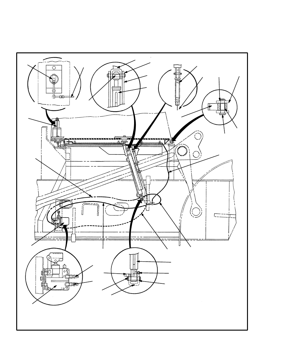
General (See FIGURE 22., FIGURE 23.)
The tilt cab arrangement uses a hand operated pump and
a hydraulic cylinder to raise and lower the cab. A hy-
draulic latch, also operated by the pump, releases the
hook that holds the cab platform to the lift truck frame.
1. PUMP
2. PORT (RAISE)
3. PORT (LOWER)
4. CYLINDER
5. CABLE FOR CAB SUPPORT
6. HOSE (RAISE)
7. HOSE (LOWER)
8. HOSE (LATCH RELEASE)
9. LATCH CYLINDER
10. SNAP RING
11. PIN
12. BUSHING
13. HANDLE
14. CAB PLATFORM
15. CAB SUPPORT
16. SPRING
FIGURE 23. TILT CAB ARRANGEMENT
1
5
6
7
2
3
8
6
11
12
10
9
11
10
11
10
13
16
4
14
15

22
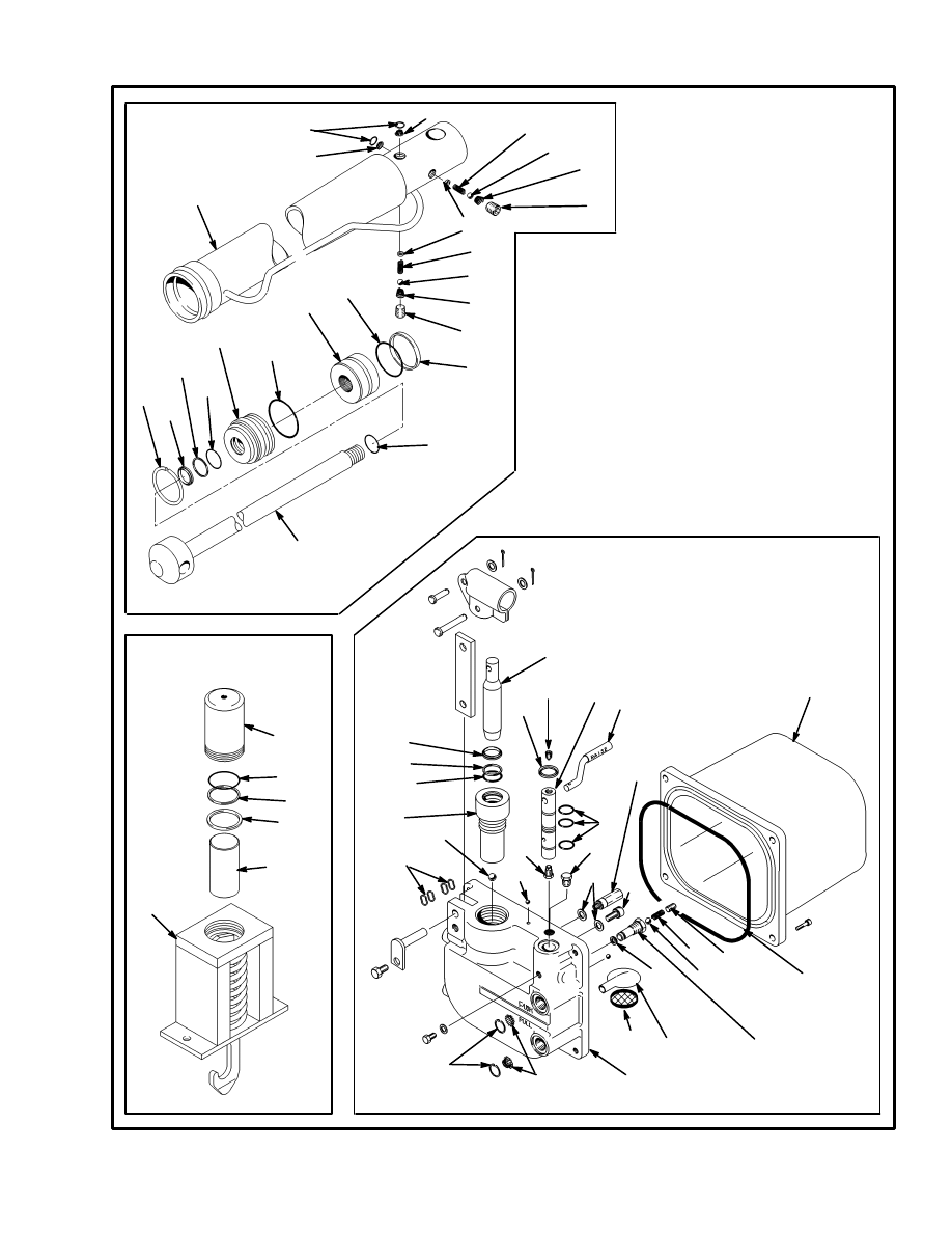
Repairs (See FIGURE 22., FIGURE 23. and
FIGURE 24.)
WARNING
Make sure the cab support is engaged before you
place any part of your body under the raised cab.
Make sure no one is under the cab when lowering the
cab.
TILT CYLINDER
(See FIGURE 22., FIGURE 23. and FIGURE 24.)
1. Raise the cab. Connect a safety chain between a hand
rail on the cab and a crossmember on the mast. The safe-
ty chain must hold the cab in the raised position when
the tilt cylinder is removed.
2. Remove the pins at the ends of the tilt cylinder. Re-
move the pin for the cable at the cab platform.
3. Disconnect the hydraulic lines at the tilt cylinder. Put
tags on the lines for identification.
4. Disassemble the tilt cylinder assembly and repair as
necessary.
5. Install the tilt cylinder in the correct position. Make
sure the cab support is installed correctly. Install the pins
and snap rings for the tilt cylinder and cable.
6. Connect the hydraulic lines to the tilt cylinder.
7. Operate pump in the RAISE position. Make sure the
cab support is in the correct position then remove the
safety chain. Lower the cab and raise it again to check
for leaks and correct operation.
LATCH (See FIGURE 23. and FIGURE 24.)
1. Remove the access panel at the back of the operator’s
compartment. Disconnect the hydraulic line at the latch.
2. Remove the capscrews that hold the latch to the cab
platform.
3. Disassemble and repair the latch as necessary.
4. Install the latch and connect the hydraulic line. Oper-
ate the pump to make sure the latch opens and closes
correctly.
PUMP (See FIGURE 23. and FIGURE 24.)
1. Disconnect the hydraulic lines at the pump. Put tags
on the lines for identification.
2. Remove the capscrews that hold the pump to the
mount.
3. Disassemble and repair the pump as necessary.
4. Install the pump and connect the hydraulic lines. Op-
erate the pump to make sure the cab raises and lowers
correctly.
23
1. CYLINDER SHELL
2. RETAINING RING
3. SCREEN
4. LOCK SCREW
5. SPRING
6. BALL
7. PLUG
8. WIPER
9. BACK–UP RING
10. O–RING
11. GLAND
12. PISTON
FIGURE 24. PARTS FOR THE TILT CAB
1
2
3
4
5
6
5
7
2
8
9
10
11
10
12
10
10
13
14
15
16
17
10
9
8
18
19
10
10
2
3
3
LATCH ASSEMBLY
TILT CYLINDER
PUMP ASSEMBLY
8
9
10
17
20
21
6
6
7
5
7
22
23
24
7
25
6
27
26
25
28
29
13. SEAL
14. ROD
15. LATCH
16. PISTON
17. CYLINDER
18. PUMP
RESERVOIR
19. PUMP BODY
20. SPOOL
21. PLUNGER
22. SET SCREW
23. LEVER
24. RELIEF VALVE
25. GASKET
26. OUTLET
27. INLET
28. ORIFICE
29. WAVE WASHER
7
5
5
6
3
13

24
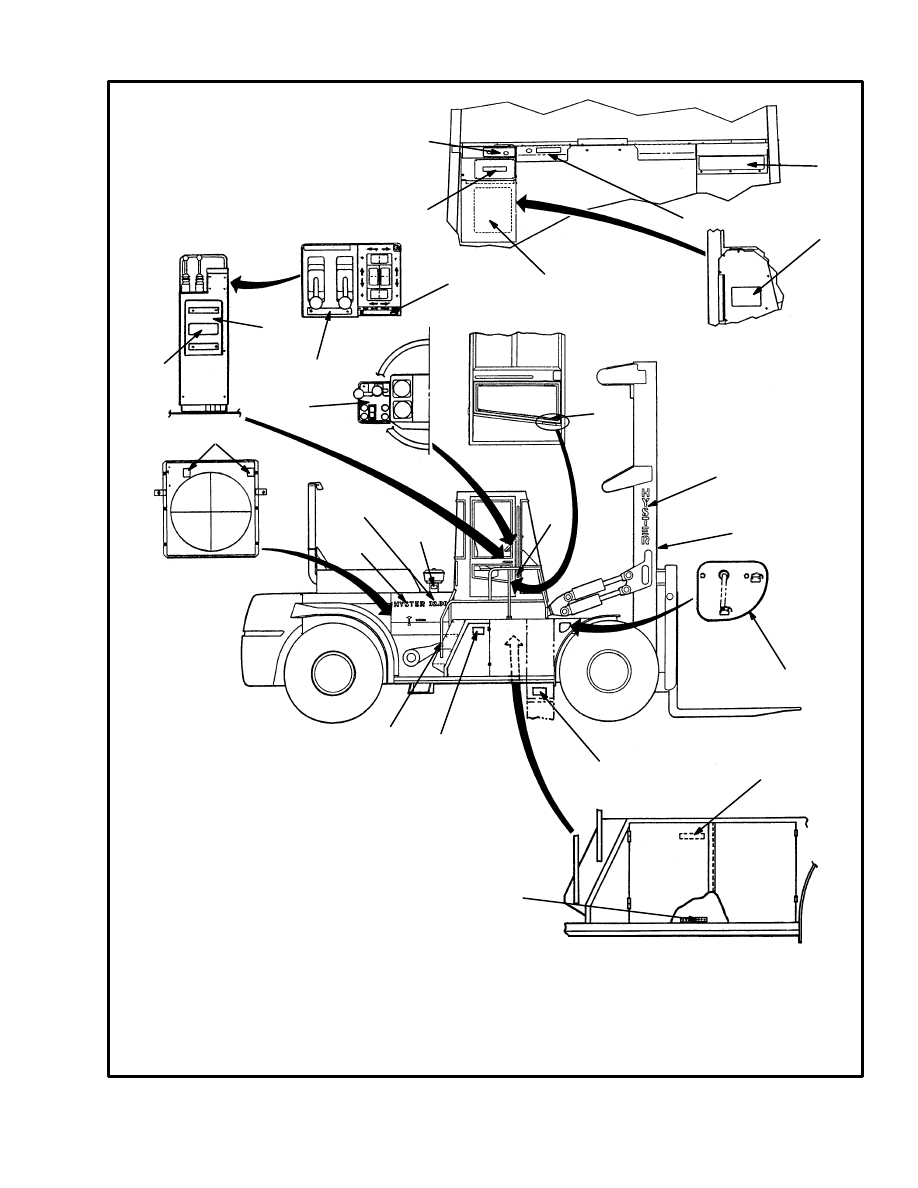
LABEL REPLACEMENT
(See FIGURE 25.)
WARNING
If labels that have warnings or cautions are dam-
aged, they must be replaced.
If a mast of a different size or an accessory carriage is
installed, the capacity rating can change. Changes in the
size of drive tires can change the capacity rating. See a
dealer for Hyster lift trucks for a replacement name-
plate. The nameplate information is a safety item and
must be correct.
1. Make sure the surface is dry and has no oil or grease.
Do not use solvent on new paint. Clean the surface of old
paint using a cleaning solvent.
2. Remove the paper from the back of the label. Do not
touch the adhesive surface.
3. Carefully hold the label in the correct position above
the surface. The label cannot be moved after it touches
the surface. Put the label on the surface. Make sure all air
is removed from under the label and the corners and
edges are tight.
If the labels or information plates are missing or dam-
aged, they must be replaced.
25
FIGURE 25. LABEL POSITIONS
12718
7. MAST CONTROL
8. ATTACHMENT CONTROL
9. CASE FOR OPERATING MANUAL
10. REPLACE OPERATING MANUAL
11. TRANSMISSION CONTROL AND
TWIST LOCK OPERATION
12. FAN WARNING
13. DOOR RELEASE
14. MODEL LABEL
15. MODEL SIZE
16. DIESEL STARTING AID
17. NO RIDERS
18. MAST LABEL
19. MAST SAFETY
20a. BATTERY DISCONNECT SWITCH
H20.00–32.00F (H440–700F)
20b. BATTERY DISCONNECT SWITCH
H440–700FS
1
2
3
4
5
6
7
8
9
10
11
12
13
14
15
16
18
19
17
20a
1. PARKING BRAKE AND
HYDRAULIC PRESSURE
2. PARKING BRAKE WARNING
3. WARNING FOR SAFETY
4. NAMEPLATE TAG
5. FUSE PANEL
6. PATENT PLATE
21a
21b
22
22
LEFT SIDE OF LIFT TRUCK
20b
21a. TILT CAB OPERATION LABEL
H20.00–32.00F (H440–700F)
21b. TILT CAB OPERATION LABEL
H440–700FS
22. HYDRAULIC TEST PORT LABEL
Document Outline
- INTRODUCTION
- REPAIRS
Wyszukiwarka
Podobne podstrony:
897390 0100SRM0449 (05 2004) UK EN
897104 0100SRM0322 (05 2004) UK EN
897506 4000SRM0521 (05 2004) UK EN
1596602 0100SRM1200 (07 2005) UK EN
897067 1400SRM0285 (05 2004) UK EN
897457 8000SRM0488 (03 1992) UK EN
1510466 1800SRM0985 (05 2005) UK EN
1580505 0700SRM1123 (05 2005) UK EN
1482603 0100SRM0793 (03 2000) UK EN
910460 1600SRM0258 (05 2004) UK EN
897066 0100SRM0284 (10 2002) UK EN
1580506 0900SRM1124 (05 2005) UK EN
897433 1800SRM0472 (04 1992) UK EN
1566270 0100SRM1118 (08 2004) UK EN
więcej podobnych podstron