COOLING SYSTEM
H3.50-5.50XM (H70-120XM) [K005, L005]
PART NO. 1466271
700 SRM 740
SAFETY PRECAUTIONS
MAINTENANCE AND REPAIR
• When lifting parts or assemblies, make sure all slings, chains, or cables are correctly
fastened, and that the load being lifted is balanced. Make sure the crane, cables, and
chains have the capacity to support the weight of the load.
• Do not lift heavy parts by hand, use a lifting mechanism.
• Wear safety glasses.
• DISCONNECT THE BATTERY CONNECTOR before doing any maintenance or repair
on electric lift trucks. Disconnect the battery ground cable on internal combustion lift
trucks.
• Always use correct blocks to prevent the unit from rolling or falling. See HOW TO PUT
THE LIFT TRUCK ON BLOCKS in the Operating Manual or the Periodic Mainte-
nance section.
• Keep the unit clean and the working area clean and orderly.
• Use the correct tools for the job.
• Keep the tools clean and in good condition.
• Always use HYSTER APPROVED parts when making repairs. Replacement parts
must meet or exceed the specifications of the original equipment manufacturer.
• Make sure all nuts, bolts, snap rings, and other fastening devices are removed before
using force to remove parts.
• Always fasten a DO NOT OPERATE tag to the controls of the unit when making repairs,
or if the unit needs repairs.
• Be sure to follow the WARNING and CAUTION notes in the instructions.
• Gasoline, Liquid Petroleum Gas (LPG), Compressed Natural Gas (CNG), and Diesel fuel
are flammable. Be sure to follow the necessary safety precautions when handling these
fuels and when working on these fuel systems.
• Batteries generate flammable gas when they are being charged. Keep fire and sparks
away from the area. Make sure the area is well ventilated.
NOTE:
The following symbols and words indicate safety information in this
manual:
WARNING
Indicates a condition that can cause immediate death or injury!
CAUTION
Indicates a condition that can cause property damage!
Cooling System
Table of Contents
TABLE OF CONTENTS
General ...............................................................................................................................................................
Description .........................................................................................................................................................
Radiator..........................................................................................................................................................
Radiator Cap ..................................................................................................................................................
Thermostat.....................................................................................................................................................
Water Pump ...................................................................................................................................................
Fan and Fan Shroud......................................................................................................................................
Drive Shaft .....................................................................................................................................................
Cooling System Checks......................................................................................................................................
Exhaust Leaks into Cooling System .............................................................................................................
Radiator Repair..................................................................................................................................................
Checks ............................................................................................................................................................
Clean ..............................................................................................................................................................
Cooling System ..............................................................................................................................................
Drain ..........................................................................................................................................................
Fill ..............................................................................................................................................................
Water Pump Repair ...........................................................................................................................................
Checks ............................................................................................................................................................
Thermostat Repair .............................................................................................................................................
Checks ............................................................................................................................................................
Fan Assembly Repair.........................................................................................................................................
Remove ...........................................................................................................................................................
Inspect ............................................................................................................................................................
Install .............................................................................................................................................................
Fan Belt Repair..................................................................................................................................................
Remove ...........................................................................................................................................................
Install .............................................................................................................................................................
Drive Shaft Repair .............................................................................................................................................
Remove ...........................................................................................................................................................
Install .............................................................................................................................................................
Troubleshooting..................................................................................................................................................
This section is for the following models:
H3.50-5.50XM (H70-120XM) [K005, L005]
©2004 HYSTER COMPANY
i

"THE
QUALITY
KEEPERS"
HYSTER
APPROVED
PARTS
700 SRM 740
Description
General
This section contains a description and repair in-
structions for the cooling system. Troubleshooting
procedures are also included in this section.
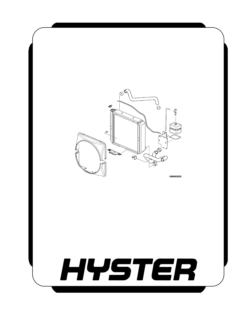
The cooling system has the following parts: radiator,
auxiliary coolant reservoir, water pump, thermostat,
fan, and a fan shroud.
Description
The purpose of the cooling system is to control the op-
erating temperature of the engine and transmission.
A centrifugal water pump circulates coolant through
passages in the engine block and radiator. A ther-
mostat is installed in the water outlet fitting on the
engine. As the coolant flows through the radiator,
the fan moves air through the radiator to help cool
the system.
The coolant is a mixture of water and antifreeze. The
antifreeze prevents the coolant from freezing in cold
weather, thereby preventing damage to the engine
and radiator. The antifreeze also prevents rust and
lubricates the water pump.
RADIATOR
The radiator is the heat exchanger for the cooling sys-
tem. The fan causes air to flow through the radiator
and reduces the temperature of the coolant. The aux-
iliary coolant reservoir is connected to the radiator by
a hose. As the engine gets hot, the coolant expands.
During expansion, coolant moves from the radiator
to the reservoir. When the engine stops, the coolant
becomes cool and contracts. Coolant in the reservoir
flows back into the radiator. In this way, the radiator
is kept filled with coolant during normal operation.
The radiator also acts as an oil cooler. Oil from the
transmission flows through a second set of coils in
the radiator tank to help control oil temperature.
RADIATOR CAP
The radiator cap is a pressure-vent type that lets the
pressure in the cooling system increase to 103 kPa
(15 psi). The pressure in the system prevents va-
por from forming in the coolant flowing to the water
pump. This action maintains the efficiency of the wa-
ter pump and performance of the cooling system. The
increase in pressure also raises the boiling point of
the coolant mixture to approximately 125 C (257 F)
at sea level.
The radiator cap has a pressure valve and a vac-
uum valve. The pressure valve is held against its
seat by a spring. The pressure valve opens when
the pressure in the cooling system exceeds 103 kPa
(15 psi). The vacuum valve is held against its seat
by another spring. The vacuum valve opens to re-
lieve the vacuum created when the coolant temper-
ature decreases. In certain conditions, this vacuum
can cause the radiator or top hose to collapse.
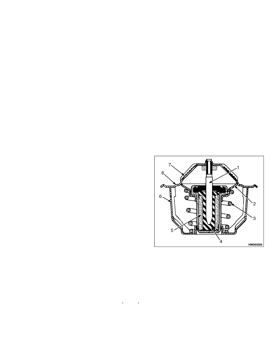
THERMOSTAT
The thermostat is a device that controls coolant flow
by opening and closing to regulate coolant tempera-
ture. See Figure 1.
1.
PISTON
2.
VALVE SEAT
3.
SPRING
4.
DIAPHRAGM
5.
WAX PELLET
6.
FRAME
7.
FLANGE
8.
VENT HOLE
Figure 1. Typical Thermostat
The thermostat uses a wax pellet to control its op-
eration. The wax pellet expands when it is heated
and contracts when it is cold. When heated, the wax
pellet pushes on the piston, causing the valve in the
thermostat to open. As the wax pellet cools, it con-
tracts and lets a spring close the valve. When the
engine is first started and the coolant is cold, the
thermostat remains closed. During this time, the
1
Radiator Repair
700 SRM 740
coolant circulates through the engine, letting it warm
quickly. As the engine becomes warm, the thermo-
stat opens, letting coolant circulate through the ra-
diator.
The opening and closing of the thermostat helps keep
the coolant within the operating limits of the system.
The same thermostat is used for summer and winter
seasons. Do not operate the engine without a ther-
mostat. The engine will take longer to warm up and
can run improperly.
WATER PUMP
The centrifugal type water pump is installed at the
front of the engine block. The inlet for the pump is
connected to the bottom of the radiator by a hose.
From the pump, coolant passes through the passages
in the engine block to the top of the radiator. The
thermostat controls the flow of coolant through the
engine and radiator.
FAN AND FAN SHROUD
The fan is used to provide airflow through the radia-
tor at all engine speeds. The fan is a puller type and
is installed on a separate hub. The fan is driven by
a drive belt from the hydraulic assembly drive shaft,
which is connected to the engine crankshaft.
The fan shroud is used to make sure the airflow from
the fan goes through the core of the radiator.
DRIVE SHAFT
The drive shaft is connected to the hydraulic pump at
one end and to the crankshaft at the other end. The
drive shaft drives the fan pulley.
Cooling System Checks
EXHAUST LEAKS INTO COOLING SYSTEM
WARNING
During engine operation, be careful not to
touch the fan, pulleys, or drive belts. Contact
with these parts can cause serious personal
injury.
To check for exhaust leaks into the cooling system,
use a kit for this purpose. Follow the manufacturer’s
instructions when doing the test.
Radiator Repair
CHECKS
NOTE: Removal and installation procedures for the
radiator are in section Frame 100 SRM 726.
To check for water flow restrictions in the radiator,
run engine until it is warm. See Figure 2. Shut en-
gine OFF and feel the radiator. The temperature
must be even across the radiator. (The radiator will
be hotter near the top radiator hose.) Cold spots on
radiator indicate restrictions.
If radiator has leaks, have it repaired by trained per-
sonnel.
CLEAN
CAUTION
Disposal of lubricants and fluids must meet lo-
cal environmental regulations.
1.
Drain cooling system. Fill cooling system with
clean water.
2.
Install radiator cap. Run engine until top radia-
tor hose is hot. Stop engine and let engine cool.
3.
Drain water from radiator. If water is dirty, fill
system with water and repeat procedure until
water is clean.
2
700 SRM 740
Radiator Repair
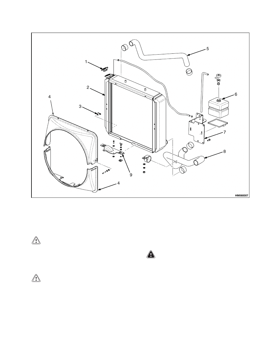
1.
RADIATOR CAP
2.
RADIATOR
3.
RADIATOR DRAIN VALVE
4.
FAN SHROUD (2 PIECES)
5.
TOP RADIATOR HOSE
6.
AUXILIARY COOLANT RESERVOIR
7.
RESERVOIR MOUNTING BRACKET
8.
BOTTOM RADIATOR HOSE
9.
DOOR SHROUD
Figure 2. Typical Radiator Arrangement
CAUTION
Follow the manufacturer’s instructions when
using a chemical radiator cleaner.
4.
If water does not clean system, use a chemical
radiator cleaner.
CAUTION
Follow the manufacturer’s instructions when
using special equipment to reverse clean the
radiator.
5.
If radiator or cooling system is very dirty or has
a restriction, use reverse cleaning method. This
method uses air pressure to force water through
radiator in opposite direction of normal flow.
WARNING
Compressed air can move particles so that they
cause injury to the user or to other personnel.
Make sure that the path of the compressed air
is away from all personnel.
Wear protective
goggles or a face shield to prevent injury to the
eyes.
6.
Check radiator fins. Clean exterior of radiator
with compressed air or water as needed.
3
Water Pump Repair
700 SRM 740
COOLING SYSTEM
Drain
WARNING
DO NOT remove the radiator cap from the radi-
ator when the engine is hot. When the radiator
cap is removed, the pressure is released from
the system. If the system is hot, the steam and
boiling coolant can cause burns.
CAUTION
Disposal of lubricants and fluids must meet lo-
cal environmental regulations.
1.
Let coolant cool to room temperature. Put a drain
pan under radiator. Remove radiator cap.
2.
Open the drain plug or remove the bottom radia-
tor hose. Remove the drain plug from the engine
block to drain the engine.
Fill
1.
Install drain plug in engine block.
2.
Install bottom radiator hose using heat-shrink
bands.
Heat shrink band with a heater (hair
dryer) until band turns brown in one spot. This
causes band to become tight enough to start en-
gine. Bands will continue to tighten with engine
use.
WARNING
Do not use an alcohol or methanol base an-
tifreeze. They are flammable and cause per-
sonal injury or damage to the lift truck.
3.
Fill cooling system with a mixture of 50% water
and 50% ethylene glycol antifreeze. The 50/50
mixture will protect cooling system to
37 C
( 35 F).
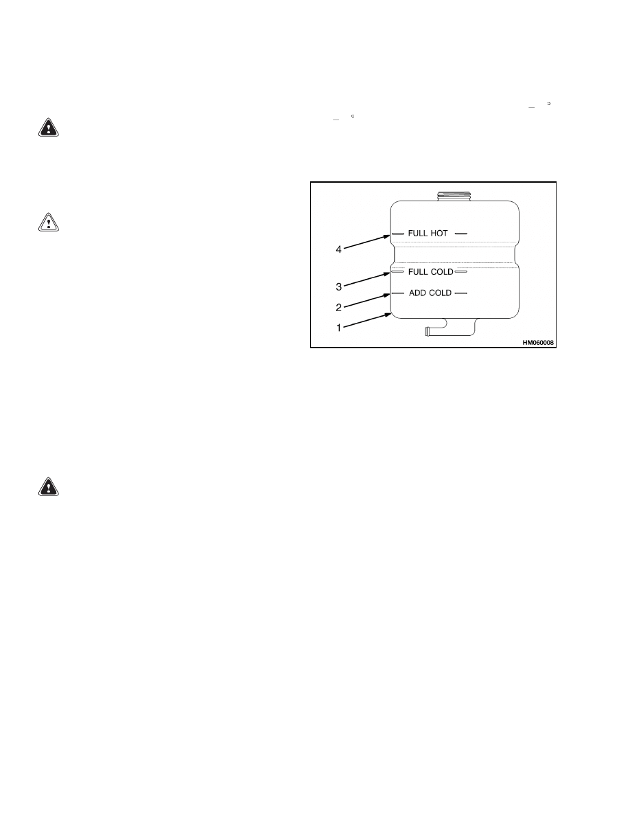
4.
Use the same coolant mixture and fill the auxil-
iary coolant reservoir to the FULL COLD mark.
See Figure 3.
1.
AUXILIARY COOLANT RESERVOIR
2.
ADD COLD MARK
3.
FULL COLD MARK
4.
FULL HOT MARK
Figure 3. Auxiliary Coolant Reservoir
5.
Start and run engine until thermostat opens.
(The top radiator hose will be warm.)
6.
Check coolant level at the auxiliary coolant reser-
voir. Add coolant as necessary to keep level be-
tween FULL COLD and FULL HOT marks.
Water Pump Repair
CHECKS
NOTE: The removal and installation procedures for
the water pump are in the Engine section.
Run engine until it is warm. Check the operation of
water pump by holding the top radiator hose. If the
pump is operating, there will be pressure surges in
the hose.
4
700 SRM 740
Fan Assembly Repair
Thermostat Repair
CHECKS
CAUTION
DO NOT operate the engine without a ther-
mostat. The engine and cooling system can be
damaged.
NOTE:
For procedures on removing and installing
the thermostat, see the Engine section for your lift
truck model.
Check the operation of the thermostat as follows:
1.
Mix a solution (33% antifreeze and water). Heat
the solution to 14 C (57 F) above the temperature
on the thermostat.
2.
Hold thermostat with a wire and put it in the
solution. Stir solution. When operating correctly,
the thermostat will open.
3.
Remove thermostat and put in a solution (33%
antifreeze and water) that is
12 C (10 F) below
the temperature on the thermostat. When op-
erating correctly, the thermostat will close. The
valve must close completely.
Fan Assembly Repair
REMOVE
WARNING
DO NOT try to repair a damaged fan. If a fan
has a bent blade or is cracked, install a new fan.
A damaged fan can break during use and cause
damage or serious injury.
1.
Remove counterweight from truck. Removal and
installation procedures for the counterweight are
in section Frame Frame 100 SRM 726.
2.
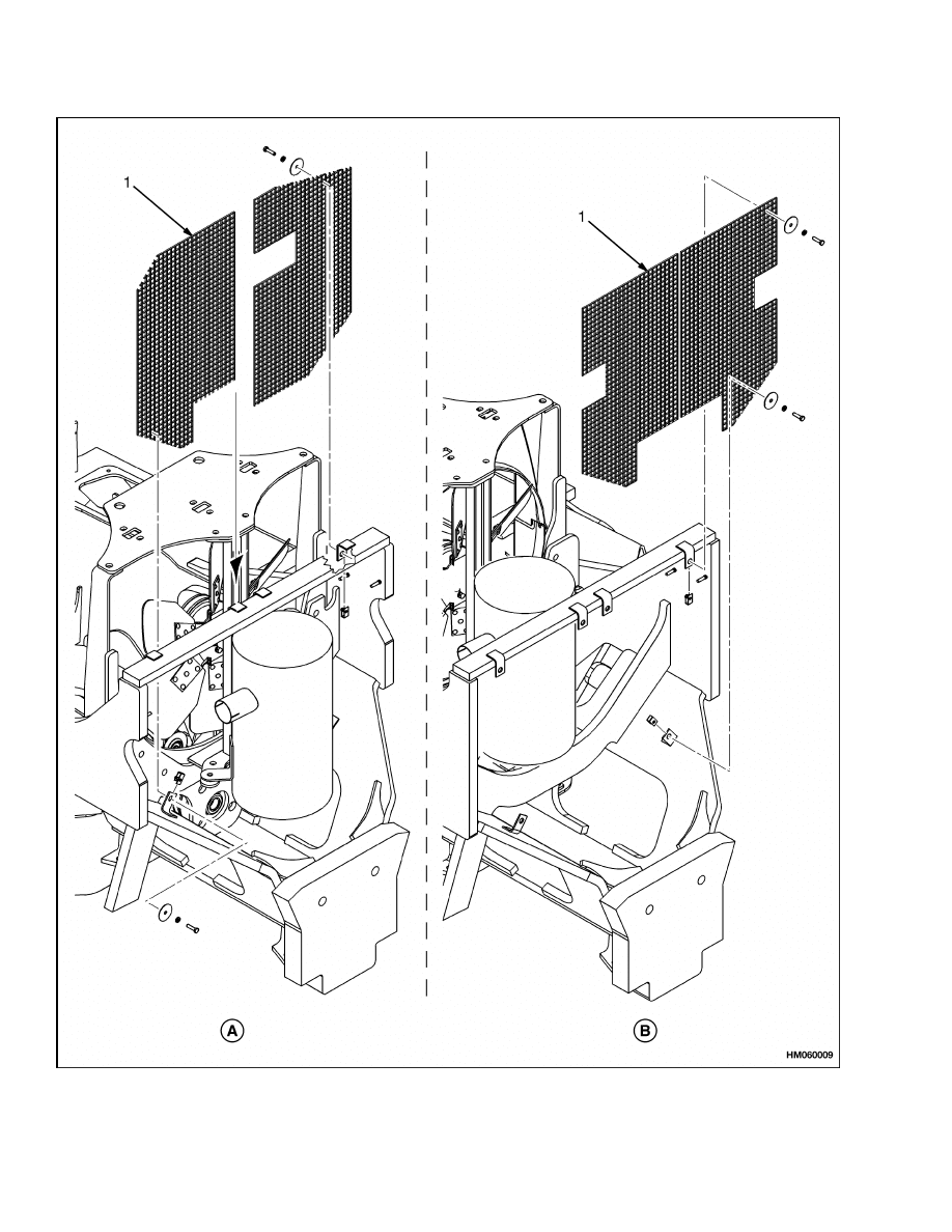
Remove safety screen as shown in Figure 4.
3.
Remove muffler from exhaust system.
Proce-
dures to remove and install muffler are in section
Frame Frame 100 SRM 726.
4.
Remove four bolts and washers securing fan
mount bracket and remove fan belt from pulley.
5.
Relieve tension on belt tensioner and take fan
belt off upper fan pulley. See Figure 5.
6.
Remove fan bracket from truck with fan and pul-
ley intact.
7.
Remove hex-head bolt from engine side of pulley
and remove pulley from fan pin.
8.
Remove four hex-head bolts from fan side of pul-
ley and remove fan.
INSPECT
Inspect fan bearings for excessive wear or damage
and replace if necessary.
INSTALL
1.
Apply adhesive only to the outside diameter of
bearings. See Figure 5.
2.
Make sure fan bearings are seated correctly in
the pulley housing.
3.
Install fan onto pulley with four hex-head bolts.
4.
Install fan pulley on fan pin. Do not dislodge fan
bearings.
5.
Install fan and fan bracket in the truck by first
placing fan belt over the pulley and pulling the
bracket back toward mounting holes. Put the
bottom bolts (with washers and rubber grom-
mets) in first and barely tighten. Then pull the
top of bracket back until top holes line up. Install
the top bolts, washers, and rubber grommets.
NOTE:
Make sure fan belt is seated on the lower pul-
ley before tightening bolts.
6.
Tighten all four mounting bolts.
7.
Install muffler in the truck.
8.
Install counterweight onto truck.
5
Fan Assembly Repair
700 SRM 740
Figure 4. Safety Screen Assembly
6
700 SRM 740
Fan Assembly Repair
Legend for Figure 4
A. 1800 TO 1830 MM WHEELBASE TRUCK
B. 2100 MM WHEELBASE TRUCK
1.
SAFETY SCREEN
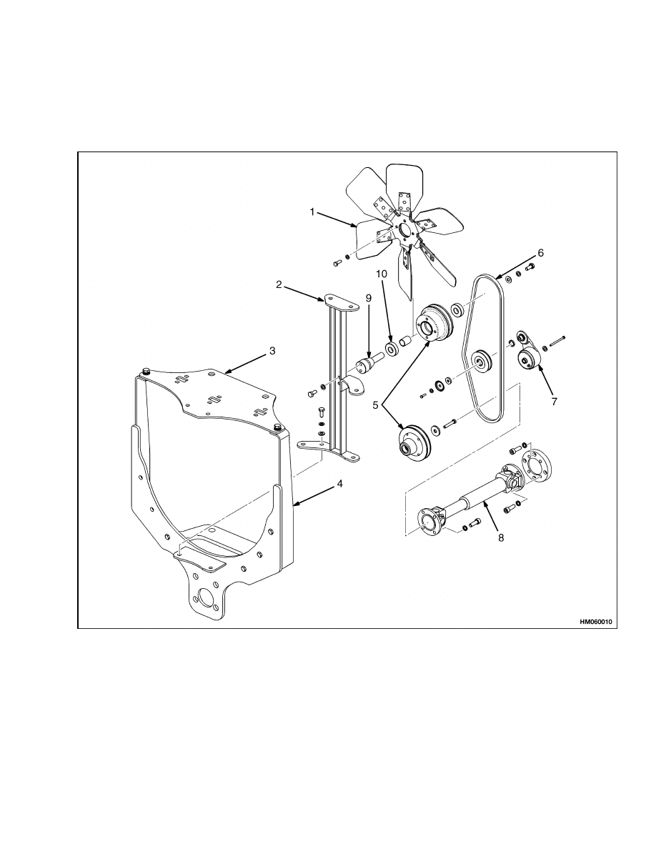
1.
FAN
2.
FAN MOUNT BRACKET
3.
PLATE
4.
MODULAR FAN MOUNT BRACKET
5.
PULLEYS
6.
FAN BELT
7.
TENSIONER
8.
DRIVE SHAFT
9.
FAN PIN
10. BEARINGS (2)
Figure 5. Fan Assembly
7

Troubleshooting
700 SRM 740
Fan Belt Repair
REMOVE
1.
Place the truck up on blocks. Refer to section
How to Put a Truck on Blocks in the Operating
Manual.
NOTE:
The belt tensioner is a nonadjustable, self-
tensioning device with two positions, tension applied
and tension relieved.
2.
Relieve tension on the belt tensioner and take fan
belt off the upper fan pulley.
3.
Remove four hex-head bolts connecting the drive
shaft to lower fan pulley, slide drive shaft back,
and remove fan belt.
INSTALL
1.
From beneath the truck, place fan belt over up-
per fan pulley, belt tensioner pulley, and lower
fan pulley.
2.
Slide drive shaft forward to mate with the lower
fan pulley.
Install four hex-head bolts and
tighten them.
3.
Apply tension to fan belt.
4.
Remove truck from the blocks. Refer to section
How to Put a Truck on Blocks in the Operating
Manual.
Drive Shaft Repair
REMOVE
1.
Remove four hex-head bolts connecting the drive
shaft to lower fan pulley. See Figure 5.
2.
Remove four hex-head bolts connecting the drive
shaft to crankshaft.
3.
Inspect drive shaft and replace if necessary.
INSTALL
1.
Install four hex-head bolts connecting the drive
shaft to crankshaft.
2.
Place fan belt over the lower fan pulley and
install four hex-head bolts connecting the drive
shaft to lower pulley.
Troubleshooting
PROBLEM
POSSIBLE CAUSE
PROCEDURE OR ACTION
Coolant leakage.
There is a leak in the radiator.
Repair radiator.
There is a leak in a radiator hose or
coolant hose.
Install new hose(s).
There is a leak from a plug or sensor
in the engine block.
Check sensors and plugs and repair
leaks.
Water pump leaks.
Install a new water pump.
Thermostat housing leaks.
Install a new thermostat housing.
Check for correct installation of the
thermostat.
Cylinder head gasket is damaged.
Install a new head gasket.
8

700 SRM 740
Troubleshooting
PROBLEM
POSSIBLE CAUSE
PROCEDURE OR ACTION
Coolant leakage. (Cont.)
Cylinder head is cracked.
Install a new cylinder head.
Engine block is cracked.
Install a new cylinder block.
The engine is too hot during
operation.
There is not enough coolant in cool-
ing system.
Check coolant level in radiator and
coolant recovery bottle. Add coolant
to correct level.
Radiator is dirty.
Drain and clean radiator. Clean ra-
diator fins with low pressure air or
water in reverse direction of normal
airflow. Be careful not to bend fins.
Refill with clean coolant.
Drive belt for water pump is not ad-
justed correctly, is worn, or is broken.
Check water pump drive belt. Adjust
or install new belt as required.
Thermostat is the wrong heat range
or does not operate correctly.
Check heat range. Install new ther-
mostat.
Cooling system has restrictions.
Drain and back-flush engine and ra-
diator. Refill with clean coolant.
Water pump worn or damaged.
Install new water pump.
Exhaust system has restrictions.
Check exhaust system. Remove re-
strictions.
Ignition timing is not correct.
Check and adjust timing.
Exhaust
leakage
into
coolant.
Head gasket(s) leaks.
Install new gasket(s).
Cylinder head is damaged.
Install new cylinder head.
9

NOTES
____________________________________________________________
____________________________________________________________
____________________________________________________________
____________________________________________________________
____________________________________________________________
____________________________________________________________
____________________________________________________________
____________________________________________________________
____________________________________________________________
____________________________________________________________
____________________________________________________________
____________________________________________________________
____________________________________________________________
____________________________________________________________
____________________________________________________________
____________________________________________________________
____________________________________________________________
____________________________________________________________
____________________________________________________________
____________________________________________________________
10


TECHNICAL PUBLICATIONS
700 SRM 740
2/04 (11/03)(8/99) Printed in United Kingdom
Document Outline
- toc
Wyszukiwarka
Podobne podstrony:
1538373 2200SRM1065 (02 2004) UK EN
897393 1800SRM0452 (02 2004) UK EN
897989 4000SRM0661 (02 2004) UK EN
1568204 0700SRM1159 (08 2005) UK EN
1554631 2000SRM1085 (03 2004) UK EN
1564283 1900SRM1107 (01 2004) UK EN
1554635 8000SRM1079 (06 2004) UK EN
897506 4000SRM0521 (05 2004) UK EN
897480 1400SRM0499 (10 2004) UK EN
1466205 2100SRM0735 (11 2004) UK EN
897067 1400SRM0285 (05 2004) UK EN
1565454 8000SRM1113 (06 2004) UK EN
1580505 0700SRM1123 (05 2005) UK EN
897509 2200SRM0524 (02 2001) UK EN
1470232 1900SRM0783 (01 2004) UK EN
więcej podobnych podstron