
NFPA 20
S t andar d f or t he
I nst al l at i on of
S t at i onar y Pu m p s f or
Fi r e Pr ot ect i on
2003 E di t i on
NFPA, 1 B at t er ym ar ch Par k , PO B ox 9 1 01 , Q u i ncy, M A 0226 9 - 9 1 01
An I nt er nat i onal C odes and S t andar ds O r g ani z at i on
NFPA L i cense Ag r eem ent
T hi s docu m ent i s cop yr i g ht ed b y t he Nat i onal Fi r e Pr ot ect i on Associ at i on ( NFPA) , 1 B at t er ym ar ch Par k , Q u i ncy, M A 0226 9 - 9 1 01 U S A.
Al l r i g ht s r eser ved.
NFPA g r ant s you a l i cense as f ol l ow s: T he r i g ht t o dow nl oad an el ect r oni c f i l e of t hi s NFPA docu m ent f or t em p or ar y st or ag e on one com p u t er
f or p u r p oses of vi ew i ng and/ or p r i nt i ng one cop y of t he NFPA docu m ent f or i ndi vi du al u se. Nei t her t he el ect r oni c f i l e nor t he har d cop y p r i nt
m ay b e r ep r odu ced i n any w ay. I n addi t i on, t he el ect r oni c f i l e m ay not b e di st r i b u t ed el sew her e over com p u t er net w or k s or ot her w i se. T he
har d cop y p r i nt m ay onl y b e u sed p er sonal l y or di st r i b u t ed t o ot her em p l oyees f or t hei r i nt er nal u se w i t hi n you r or g ani z at i on.

IMPORTANT NOTICES AND DISCLAIMERS CONCERNING NFPA DOCUMENTS
NOTICE AND DISCLAIMER OF LIABILITY CONCERNING THE USE OF NFPA DOCUMENTS
NFPA codes, standards, recommended practices, and guides, of which the document contained herein is one, are de-
veloped through a consensus standards development process approved by the American National S tandards I nstitute.
This process brings together volunteers representing varied viewpoints and interests to achieve consensus on fire and
other safety issues. W hile the NFPA administers the process and establishes rules to promote fairness in the develop-
ment of consensus, it does not independently test, evaluate, or verify the accuracy of any information or the soundness
of any judgments contained in its codes and standards.
The NFPA disclaims liability for any personal injury, property or other damages of any nature whatsoever, whether
special, indirect, consequential or compensatory, directly or indirectly resulting from the publication, use of, or reliance
on this document. The NFPA also makes no guaranty or warranty as to the accuracy or completeness of any information
published herein.
In issuing and making this document available, the NFPA is not undertaking to render professional or other services
for or on behalf of any person or entity. Nor is the NFPA undertaking to perform any duty owed by any person or entity
to someone else. Anyone using this document should rely on his or her own independent judgment or, as appropriate,
seek the advice of a competent professional in determining the ex ercise of reasonable care in any given circumstances.
The NFPA has no power, nor does it undertake, to police or enforce compliance with the contents of this document.
Nor does the NFPA list, certify, test or inspect products, designs, or installations for compliance with this document.
Any certification or other statement of compliance with the requirements of this document shall not be attributable to
the NFPA and is solely the responsibility of the certifier or maker of the statement.

AD D I TI ON AL N OTI C E S AN D D I S C L AI ME R S
U p d ating of N FP A D oc ume nts
Users of NF P A c odes, standards, rec om m ended p rac tic es, and gu ides shou ld be aware that
these doc u m ents m ay be su p erseded at any tim e by the issu anc e of new editions or m ay be
am ended from tim e to tim e throu gh the issu anc e of T entativ e Interim Am endm ents. An offi-
c ial NF P A doc u m ent at any p oint in tim e c onsists of the c u rrent edition of the doc u m ent
together with any T entativ e Interim Am endm ents and any E rrata then in effec t. In order to
determ ine whether a giv en doc u m ent is the c u rrent edition and whether it has been am ended
throu gh the issu anc e of T entativ e Interim Am endm ents or c orrec ted throu gh the issu anc e of
E rrata, c onsu lt ap p rop riate NF P A p u blic ations su c h as the National F ire Codes
®
Su bsc rip tion
Serv ic e, v isit the NF P A website at www.nfp a.org, or c ontac t the NF P A at the address listed
below.
I nte rp re tations of N FP A D oc ume nts
A statem ent, written or oral, that is not p roc essed in ac c ordanc e with Sec tion 6 of the R eg-
u lations G ov erning Com m ittee P rojec ts shall not be c onsidered the offic ial p osition of NF P A
or any of its Com m ittees and shall not be c onsidered to be, nor be relied u p on as, a F orm al
Interp retation.
P ate nts
T he NF P A does not take any p osition with resp ec t to the v alidity of any p atent rights
asserted in c onnec tion with any item s whic h are m entioned in or are the su bjec t of NF P A
c odes, standards, rec om m ended p rac tic es, and gu ides, and the NF P A disc laim s liability for
the infringem ent of any p atent resu lting from the u se of or relianc e on these doc u m ents.
Users of these doc u m ents are exp ressly adv ised that determ ination of the v alidity of any su c h
p atent rights, and the risk of infringem ent of su c h rights, is entirely their own resp onsibility .
NF P A adheres to ap p lic able p olic ies of the Am eric an National Standards Institu te with
resp ec t to p atents. F or fu rther inform ation c ontac t the NF P A at the address listed below.
L aw and R e g ulations
Users of these doc u m ents shou ld c onsu lt ap p lic able federal, state, and loc al laws and reg-
u lations. NF P A does not, by the p u blic ation of its c odes, standards, rec om m ended p rac tic es,
and gu ides, intend to u rge ac tion that is not in c om p lianc e with ap p lic able laws, and these
doc u m ents m ay not be c onstru ed as doing so.
C op yrig hts
T his doc u m ent is c op y righted by the NF P A. It is m ade av ailable for a wide v ariety of both
p u blic and p riv ate u ses. T hese inc lu de both u se, by referenc e, in laws and regu lations, and
u se in p riv ate self-regu lation, standardiz ation, and the p rom otion of safe p rac tic es and
m ethods. B y m aking this doc u m ent av ailable for u se and adop tion by p u blic au thorities and
p riv ate u sers, the NF P A does not waiv e any rights in c op y right to this doc u m ent.
Use of NF P A doc u m ents for regu latory p u rp oses shou ld be ac c om p lished throu gh adop -
tion by referenc e. T he term “adop tion by referenc e” m eans the c iting of title, edition, and
p u blishing inform ation only . Any deletions, additions, and c hanges desired by the adop ting
au thority shou ld be noted sep arately in the adop ting instru m ent. In order to assist NF P A in
following the u ses m ade of its doc u m ents, adop ting au thorities are requ ested to notify the
NF P A (Attention: Sec retary , Standards Cou nc il) in writing of su c h u se. F or tec hnic al assis-
tanc e and qu estions c onc erning adop tion of NF P A doc u m ents, c ontac t NF P A at the address
below.
For Furthe r I nformation
All qu estions or other c om m u nic ations relating to NF P A c odes, standards, rec om m ended
p rac tic es, and gu ides and all requ ests for inform ation on NF P A p roc edu res gov erning its
c odes and standards dev elop m ent p roc ess, inc lu ding inform ation on the p roc edu res for
requ esting F orm al Interp retations, for p rop osing T entativ e Interim Am endm ents, and for
p rop osing rev isions to NF P A doc u m ents du ring regu lar rev ision c y c les, shou ld be sent to
NF P A headqu arters, addressed to the attention of the Sec retary , Standards Cou nc il, NF P A,
1 B attery m arc h P ark, P .O . B ox 9 1 0 1 , Q u inc y , M A 0 2 2 69 -9 1 0 1 .
F or m ore inform ation abou t NF P A, v isit the NF P A website at www.nfp a.org.

Copyright © 2003, National Fire Protection Association, All Rights Reserved
NFPA 20
Standard for the
Installation of Stationary Pumps for Fire Protection
2003 Edition
This edition of NFPA 20, Standard for the Installation of Stationary Pumps for Fire Protection, was
prepared by the Technical Committee on Fire Pumps and acted on by NFPA at its May Association
Technical Meeting held May 18–21, 2003, in D allas, TX . It was issued by the Standards Council on
July 18, 2003, with an effective date of August 7, 2003, and supersedes all previous editions.
This edition of NFPA 20 was approved as an American National Standard on July 18, 2003.
Origin and Development of NFPA 20
The first National Fire Protection Association standard for automatic sprinklers was published
in 1896 and contained paragraphs on steam and rotary fire pumps.
The Committee on Fire Pumps was organized in 1899 with five members from underwriter
associations. Today, the committee membership includes representatives of Underwriters
Laboratories of both the United States and Canada, Insurance Services Offices, Factory Mu-
tual, Industrial Risk Insurers, national trade associations, state government, engineering or-
ganizations, and private individuals.
Early fire pumps were only secondary supplies for sprinklers, standpipes, and hydrants and
were started manually. Today, fire pumps have greatly increased in number and in applica-
tions —
many are the major or only water supply, and almost all are started automatically.
Early pumps usually took suction by lift from standing or flowing water supplies because the
famed National Standard Steam Fire Pump and rotary types suited that service. Ascendancy of
the centrifugal pump resulted in positive head supply to horizontal shaft pumps from public
water supplies and aboveground tanks. Later, vertical shaft turbine–type pumps were lowered
into wells or into wet pits supplied from ponds or other belowground sources of water.
Gasoline engine-driven pumps first appeared in this standard in 1913. From an early status
of relative unreliability and of supplementary use only, first spark-ignited gasoline engines
and then compression ignition diesels have steadily developed engine-driven pumps to a
place alongside electric-driven units for total reliability.
Fire protection now calls for larger pumps, higher pressures, and more varied units for a wide
range of systems protecting both life and property. H ydraulically calculated and designed sprin-
kler and special fire protection systems have changed concepts of water supply completely.
Since the formation of this Committee, each edition of NFPA 20 has incorporated appro-
priate provisions to cover new developments and has omitted obsolete provisions. NFPA
action on successive editions has been taken in the following years —
1907, 1910-13, 1915,
1918-21, 1923-29, 1931-33, 1937, 1939, 1943, 1944, 1946-48, 1951, 1953, 1955, 1957, 1959-72,
1974, 1976, 1978, 1980, 1983, 1987, 1990, 1993, 1996, and 1999.
The 1990 edition included several amendments with regard to some of the key components
associated with electric-driven fire pumps. In addition, amendments were made to allow the
document to conform more closely to the NFPA M anual of Style.
The 1993 edition included significant revisions to Chapters 6 and 7 with regard to the arrange-
ment of the power supply to electric-driven fire pumps. These clarifications were intended to
provide the necessary req uirements in order to make the system as reliable as possible.
20
–1

The 1996 edition continued the changes initiated in the 1993 edition as Chapters 6 and 7, which addressed electric
drives and controllers, underwent significant revision. New information was also added regarding engine-cooling
provisions, earthquake protection, and backflow preventers. Chapter 5, which addressed provisions for high-rise
buildings, was removed, as were capacity limitations on in-line and end-suction pumps. Additionally, provisions regard-
ing suction pipe fittings were updated.
The 1999 edition of the standard included requirements for positive displacement pumps for both water mist and
foam systems. The document title was revised to reflect this change, since the 1999 edition addressed requirements for
pumps other than centrifugal. Enforceable language was added, particularly regarding protection of equipment.
Revisions for the 2003 edition include updating the document to the latest edition of the NFPA Manual of Style. Provisions
were also added to address the use of fire pump drivers using variable speed pressure limiting control. Acceptance test
criteria were added to the document for replacement of critical path components of a fire pump installation.
20
–2
INSTALLATION OF STATIONARY PUMPS FOR FIRE PROTECTION
2003 Edition

Technical Committee on Fire Pumps
John D. Jensen, Chair
Fire Protection Consultants, ID [SE]
Frank L. Moore, Secretary
Moore Pump and Equipment, Inc., MS [IM]
(Alt. to A. A. Dorini)
John R. Bell,
U.S. DOE–Fluor Daniel Hanford, Inc., W A [U]
Rep. U.S. Department of Energy
Harold D. Brandes, Jr.,
Duke Power Co., NC [U]
Rep. Edison Electric Institute
Pat D. Brock,
Oklahoma State University, OK [SE]
Phillip A. Davis,
Kemper Insurance Companies, IL [I]
Manuel J. DeLerno,
S-P-D Inc., IL [M]
Rep. Illinois Fire Prevention Association
David L. Dixon,
Security Fire Protection, TN [IM]
Rep. National Fire Sprinkler Association
Alan A. Dorini,
Gulfstream Pump & Equipment, FL [IM]
George W. Flach,
George W . Flach Consultant, Inc., LA [SE]
Paul F. Hart,
GE Global Asset Protection Services, IL [I]
Bill M. Harvey,
Harvey & Associates, Inc., SC [IM]
Rep. American Fire Sprinkler Association, Inc.
Thomas W. Jaeger,
Gage-Babcock & Associates, Inc., V A [SE]
Hatem Ezzat Kheir,
Kheir Group, Egypt [IM]
Timothy S. Killion,
Peerless Pump Company, IN [M]
John R. Kovacik,
Underwriters Laboratories Inc., IL [RT]
R. T. Leicht,
State of Delaware, DE [E]
Rep. International Fire Marshals Association
Stephen A. Mezsick,
Eli Lilly and Company, IN [U]
Rep. American Chemistry Council
David S. Mowrer,
HSB Professional Loss Control, TN [I]
Howard W. Packer,
The DuPont Company, DE [U]
Rep. NFPA Industrial Fire Protection Section
Gayle Pennel,
Schirmer Engineering Corporation, IL [I]
Milosh T. Puchovsky,
Arup Fire, MA [SE]
Tom Reser,
Edwards Manufacturing, OR [M]
Matthew Roy,
Armstrong Darling, Inc., Canada [M]
R. Schneider,
Joslyn Clark Controls, SC [M]
Rep. National Electrical Manufacturers Association
Hansford Stewart,
ITT A-C Fire Pump Systems, IL [M]
John Whitney,
Clarke Detroit Diesel-Allison, OH [M]
Rep. Engine Manufacturers Association
William E. Wilcox,
FM Global, MA [I]
Rep. FM Global/FM Research
Alternates
Phillip Brown,
American Fire Sprinkler Association, Inc.,
TX [IM]
(Alt. to B. M. Harvey)
Hugh D. Castles,
Entergy Services, Inc., LA [U]
(Alt. to H. D. Brandes)
Tim Fernholtz,
Sterling Fluid Systems-Peerless Pump,
CA [M]
(Alt. to T. S. Killion)
David Fuller,
FM Approvals, RI [I]
(Alt. to W . E. W ilcox)
Scott G. Grieb,
Fire Concepts, Inc., IL [I]
(Alt. to P. A. Davis)
Kenneth E. Isman,
National Fire Sprinkler Association,
NY [IM]
(Alt. to D. L. Dixon)
James J. Koral,
General Motors, NY [U]
(Alt. to H. W . Packer)
Gary Lauer,
ITT A-C Fire Pump Systems, IL [M]
(Alt. to H. Stewart)
Terence A. Manning,
Manning Electrical Systems, Inc.,
IL [IM]
(Alt. to M. J. DeLerno)
Emil W. Misichko,
Underwriters Laboratories Inc., IL [RT]
(Alt. to J. R. Kovacik)
Michael R. Moran,
State of Delaware, DE [E]
(Alt. to R. T. Leicht)
Jeffrey R. Roberts,
GE Global Asset Protection Services,
MS [I]
(Alt. to P. F. Hart)
Jeffrey L. Robinson,
W estinghouse Savannah River Co.,
SC [U]
(Alt. to J. R. Bell)
Arnold R. Sdano,
Fairbanks Morse Pump, KS [M]
(V oting Alt. to HI Rep.)
William F. Stelter,
Master Control Systems, Inc., IL [M]
(Alt. to R. Schneider)
Steven L. Touchton,
Edwards Manufacturing, OR [M]
(Alt. to T. Reser)
Nonvoting
Edward D. Leedy,
Naperville, IL
(Member Emeritus)
James W. Nolan,
James W . Nolan Company, IL
(Member Emeritus)
Dana R. Haagensen,
NFPA Staff Liaison
This list represents the membership at the time the Committee was balloted on the final text of this edition. Since that time,
changes in the membership may have occurred. A key to classifications is found at the back of the document.
NOTE: Membership on a committee shall not in and of itself constitute an endorsement of the Association or
any document developed by the committee on which the member serves.
Committee Scope:
This Committee shall have primary responsibility for documents on the selection and
installation of stationary pumps supplying water or special additives including but not limited to foam
concentrates for private fire protection, including suction piping, valves and auxiliary equipment, electric
drive and control equipment, and internal combustion engine drive and control equipment.
20
–3
COMMITTEE PERSONNEL
2003 Edition

Contents
Chapter 1
Administration
................................. 20– 6
1.1
Scope
................................................ 20– 6
1.2
Purpose
.............................................. 20– 6
1.3
Application
......................................... 20– 6
1.4
Retroactivity
........................................ 20– 6
1.5
Equivalency
......................................... 20– 6
1.6
Units
................................................. 20– 6
Chapter 2
Referenced Publications
.................... 20– 7
2.1
General
.............................................. 20– 7
2.2
NFPA Publications
................................ 20– 7
2.3
Other Publications
................................ 20– 7
Chapter 3
Definitions
...................................... 20– 7
3.1
General
.............................................. 20– 7
3.2
NFPA Official Definitions
....................... 20– 7
3.3
General Definitions
............................... 20– 7
Chapter 4
Reserved
........................................ 20–10
Chapter 5
General Requirements
....................... 20–10
5.1
Pumps
............................................... 20–10
5.2
Approval Required
............................... 20–10
5.3
Pump Operation
.................................. 20–10
5.4
Fire Pump Unit Performance
.................. 20–10
5.5
Certified Shop Test
............................... 20–10
5.6
Liquid Supplies
.................................... 20–11
5.7
Pumps and Drivers
................................ 20–11
5.8
Centrifugal Fire Pump Capacities
............. 20–11
5.9
Nameplate
.......................................... 20–11
5.10
Pressure Gauges
................................... 20–11
5.11
Circulation Relief Valve
.......................... 20–12
5.12
Equipment Protection
........................... 20–12
5.13
Pipe and Fittings
.................................. 20–12
5.14
Suction Pipe and Fittings
....................... 20–13
5.15
Discharge Pipe and Fittings
.................... 20–14
5.16
Valve Supervision
.................................. 20–14
5.17
Protection of Piping Against Damage
Due to Movement
................................. 20–14
5.18
Relief Valves for Centrifugal Pumps
.......... 20–14
5.19
Water Flow Test Devices
......................... 20–15
5.20
Power Supply Dependability
................... 20–15
5.21
Shop Tests
.......................................... 20–15
5.22
Pump Shaft Rotation
............................. 20–16
5.23
Alarms
............................................... 20–16
5.24
Pressure Maintenance (Jockey or
Make-Up) Pumps
................................. 20–16
5.25
Summary of Centrifugal Fire Pump
Data
.................................................. 20–16
5.26
Backflow Preventers and Check Valves
....... 20–17
5.27
Earthquake Protection
........................... 20–17
5.28
Packaged Fire Pump Systems
................... 20–18
5.29
Field Acceptance Test of Pump Units
........ 20–18
Chapter 6
Centrifugal Pumps
............................ 20–18
6.1
General
.............................................. 20–18
6.2
Factory and Field Performance
................ 20–18
6.3
Fittings
............................................... 20–18
6.4
Foundation and Setting
......................... 20–18
6.5
Connection to Driver and Alignment
........ 20–18
Chapter 7
V ertical Shaft Turbine–Type Pumps
...... 20–18
7.1
General
.............................................. 20–18
7.2
Water Supply
....................................... 20–19
7.3
Pump
................................................ 20–20
7.4
Installation
......................................... 20–21
7.5
Driver
................................................ 20–21
7.6
Operation and Maintenance
................... 20–21
Chapter 8
Positive Displacement Pumps
.............. 20–22
8.1
General
.............................................. 20–22
8.2
Foam Concentrate and Additive Pumps
..... 20–22
8.3
Water Mist System Pumps
....................... 20–22
8.4
Fittings
............................................... 20–22
8.5
Pump Drivers
...................................... 20–23
8.6
Controllers
......................................... 20–23
8.7
Foundation and Setting
......................... 20–23
8.8
Driver Connection and Alignment
............ 20–23
8.9
Flow Test Devices
.................................. 20–23
Chapter 9
Electric Drive for Pumps
.................... 20–23
9.1
General
.............................................. 20–23
9.2
Power Source(s)
................................... 20–23
9.3
Power Supply Lines
............................... 20–24
9.4
Voltage Drop
....................................... 20–24
9.5
Motors
............................................... 20–25
9.6
On-Site Standby Generator Systems
.......... 20–25
Chapter 10
Electric-Drive Controllers and
Accessories
.................................... 20–26
10.1
General
.............................................. 20–26
10.2
Location
............................................. 20–26
10.3
Construction
....................................... 20–26
10.4
Components
....................................... 20–27
10.5
Starting and Control
............................. 20–29
10.6
Controllers Rated in Excess of 600 V
......... 20–30
10.7
Limited Service Controllers
.................... 20–31
10.8
Power Transfer for Alternate Power
Supply
............................................... 20–31
10.9
Controllers for Additive Pump Motors
....... 20–33
Chapter 11
Diesel Engine Drive
......................... 20–33
11.1
General
.............................................. 20–33
11.2
Engines
.............................................. 20–33
11.3
Pump and Engine Protection
.................. 20–37
11.4
Fuel Supply and Arrangement
................. 20–37
11.5
Engine Exhaust
.................................... 20–38
11.6
Driver System Operation
........................ 20–38
20
–4
INSTALLATION OF STATIONARY PUMPS FOR FIRE PROTECTION
2003 Edition

Chapter 12
Engine Drive Controllers
.................. 20–39
12.1
Application
......................................... 20–39
12.2
Location
............................................. 20–39
12.3
Construction
....................................... 20–39
12.4
Components
....................................... 20–40
12.5
Starting and Control
............................. 20–40
12.6
Air-Starting Engine Controllers
................ 20–42
Chapter 13
Steam Turbine Drive
........................ 20–44
13.1
General
.............................................. 20–44
13.2
Turbine
.............................................. 20–44
13.3
Installation
......................................... 20–45
Chapter 14
Acceptance Testing, Performance,
and Maintenance
............................ 20–45
14.1
Hydrostatic Tests and Flushing
................ 20–45
14.2
Field Acceptance Tests
........................... 20–45
14.3
Manuals, Special Tools, and Spare Parts
..... 20–47
14.4
Periodic Inspection, Testing, and
Maintenance
....................................... 20–47
14.5
Component Replacement
...................... 20–47
Annex A
Explanatory Material
........................... 20–47
Annex B
Possible Causes of Pump Troubles
......... 20–76
Annex C
Informational References
.................... 20–80
Index
............................................................. 20–81
20
–5
CONTENTS
2003 Edition

NFPA 20
Standard for the
Installation of Stationary Pumps
for Fire Protection
2003 Edition
IMPORTANT NOTE: This NFPA document is made available for
use subject to important notices and legal disclaimers. These notices
and disclaimers appear in all publications containing this document
and may be found under the heading “Important Notices and Dis-
claimers Concerning NFPA Documents.” They can also be obtained
on request from NFPA or viewed at www.nfpa.org/disclaimers.
NOTICE: An asterisk (*) following the number or letter
designating a paragraph indicates that explanatory material
on the paragraph can be found in Annex A.
Changes other than editorial are indicated by a vertical
rule beside the paragraph, table, or figure in which the
change occurred. These rules are included as an aid to the
user in identifying changes from the previous edition. Where
one or more complete paragraphs have been deleted, the de-
letion is indicated by a bullet (•) between the paragraphs that
remain.
A reference in brackets [ ] following a section or paragraph
indicates material that has been extracted from another NFPA
document. As an aid to the user, Annex C lists the complete
title and edition of the source documents for both mandatory
and nonmandatory extracts. Editorial changes to extracted
material consist of revising references to an appropriate divi-
sion in this document or the inclusion of the document num-
ber with the division number when the reference is to the
original document. Requests for interpretations or revisions
of extracted text shall be sent to the technical committee re-
sponsible for the source document.
Information on referenced publications can be found in
Chapter 2 and Annex C.
Chapter 1
Administration
1.1* Scope.
1.1.1
This standard deals with the selection and installation
of pumps supplying liquid for private fire protection.
1.1.2
Items considered include liquid supplies; suction, dis-
charge, and auxiliary equipment; power supplies; electric
drive and control; diesel engine drive and control; steam tur-
bine drive and control; and acceptance tests and operation.
1.1.3
This standard does not cover system liquid supply
capacity and pressure requirements, nor does it cover re-
quirements for periodic inspection, testing, and mainte-
nance of fire pump systems.
1.1.4
This standard does not cover the requirements for in-
stallation wiring of fire pump units.
1.2 Purpose.
The purpose of this standard is to provide a rea-
sonable degree of protection for life and property from fire
through installation requirements for stationary pumps for
fire protection based upon sound engineering principles, test
data, and field experience.
1.3 Application.
1.3.1
This standard shall apply to centrifugal single-stage and
multistage pumps of the horizontal or vertical shaft design
and positive displacement pumps of the horizontal or vertical
shaft design.
1.3.2
Requirements are established for the design and instal-
lation of single-stage and multistage pumps, pump drivers,
and associated equipment.
1.4 Retroactivity.
The provisions of this standard reflect a con-
sensus of what is necessary to provide an acceptable degree of
protection from the hazards addressed in this standard at the
time the standard was issued.
1.4.1
Unless otherwise specified, the provisions of this stan-
dard shall not apply to facilities, equipment, structures, or
installations that existed or were approved for construction
or installation prior to the effective date of the standard.
Where specified, the provisions of this standard shall be
retroactive.
1.4.2
In those cases where the authority having jurisdiction
determines that the existing situation presents an unaccept-
able degree of risk, the authority having jurisdiction shall be
permitted to apply retroactively any portion of this standard
deemed appropriate.
1.4.3
The retroactive requirements of this standard shall be
permitted to be modified if their application clearly would be
impractical in the judgment of the authority having jurisdic-
tion, and only where it is clearly evident that a reasonable
degree of safety is provided.
1.5 Equivalency.
Nothing in this standard is intended to pre-
vent the use of systems, methods, or devices of equivalent or
superior quality, strength, fire resistance, effectiveness, dura-
bility, and safety over those prescribed by this standard.
1.5.1
Technical documents shall be submitted to the authority
having jurisdiction to demonstrate equivalency.
1.5.2
The system, method, or device shall be approved for the
intended purpose by the authority having jurisdiction.
1.6 Units.
1.6.1
Metric units of measurement in this standard are in
accordance with the modernized metric system known as the
International System of Units (SI).
1.6.2
Liter and bar in this standard are outside of but recog-
nized by SI.
1.6.3
Units are listed in Table 1.6.3 with conversion factors.
1.6.4 Conversion.
The conversion procedure is to multiply the
quantity by the conversion factor and then round the result to an
appropriate number of significant digits.
1.6.5 Trade Sizes.
Where industry utilizes nominal dimen-
sions to represent materials, products, or performance, direct
conversions have not been utilized and appropriate trade sizes
have been included.
20
–6
INSTALLATION OF STATIONARY PUMPS FOR FIRE PROTECTION
2003 Edition

Chapter 2
Referenced Publications
2.1 General.
The documents or portions thereof listed in this
chapter are referenced within this standard and shall be con-
sidered part of the requirements of this document.
2.2 NFPA Publications.
National Fire Protection Association,
1 Batterymarch Park, P.O. Box 9101, Quincy, MA 02269-9101.
NFPA 13, Standard for the Installation of Sprinkler Systems, 2002
edition.
NFPA 24, Standard for the Installation of Private Fire Service
Mains and Their Appurtenances, 2002 edition.
NFPA 25, Standard for the Inspection, Testing, and Maintenance
of W ater-Based Fire Protection Systems, 2002 edition.
NFPA 37, Standard for the Installation and Use of Stationary
Combustion Engines and Gas Turbines, 2002 edition.
NFPA 51B, Standard for Fire Prevention During W elding, Cut-
ting, and Other Hot W ork, 2003 edition.
NFPA 70, National Electrical Code
®
, 2002 edition.
NFPA 110, Standard for Emergency and Standby Power Systems,
2002 edition.
NFPA 1963, Standard for Fire Hose Connections, 2003 edition.
2.3 Other Publications.
2.3.1 AGMA Publication.
American Gear Manufacturers Asso-
ciation, 1500 King Street, Suite 201, Alexandria, VA 22314-2730.
AGMA 390.03, Handbook for Helical and Master Gears, 1995.
2.3.2 ANSI Publications.
American National Standards Insti-
tute, Inc., 11 West 42nd Street, New York, NY 10036.
ANSI/IEEE C62.1, IEEE Standard for Gapped Silicon-Carbide
Surge Arresters for AC Power Circuits, 1989.
ANSI/IEEE C62.11, IEEE Standard for Metal-Oxide Surge Ar-
resters for Alternating Current Power Circuits (>1 kV), 1999.
ANSI/IEEE C62.41, IEEE Recommended Practice for Surge Voltages
in L ow-Voltage AC Power Circuits, 1991.
2.3.3 ASTM Publication.
American Society for Testing and
Materials, 100 Barr Harbor Drive, West Conshohocken, PA
19428-2959.
IEEE/ ASTM SI10, Standard for Use of the International System
of Units (SI): The Modern Metric System, 2003.
2.3.4 HI Publications.
Hydraulics Institute, 1230 Keith Build-
ing, Cleveland, OH 44115.
Hydraulics Institute Standards for Centrifugal, Rotary and Recip-
rocating Pumps, 14th ed., 1983.
HI 3.6, Rotary Pump Tests, 1994.
2.3.5 NEMA Publications.
National Electrical Manufacturers
Association, 1300 N. 17th Street, Suite 1847, Rosslyn, VA 22209.
NEMA Industrial Control and Systems Standards, ICS 2.2,
Maintenance of Motor Controllers After a Fault Condition, 1983.
NEMA MG-1, Motors and Generators, 1998.
2.3.6 UL Publications.
Underwriters Laboratories Inc.,
333 Pfingsten Road, Northbrook, IL 60062-2096.
ANSI/UL 508, Standard for Industrial Control Eq uipment, 1999.
Chapter 3
Definitions
3.1 General.
The definitions contained in this chapter shall
apply to the terms used in this standard. Where terms are not
included, common usage of the terms shall apply.
3.2 NFPA Official Definitions.
3.2.1* Approved.
Acceptable to the authority having jurisdic-
tion.
3.2.2* Authority Having Jurisdiction ( AHJ) .
An organization,
office, or individual responsible for enforcing the require-
ments of a code or standard, or for approving equipment,
materials, an installation, or a procedure.
3.2.3* Listed.
Equipment, materials, or services included in a
list published by an organization that is acceptable to the author-
ity having jurisdiction and concerned with evaluation of products
or services, that maintains periodic inspection of production of
listed equipment or materials or periodic evaluation of services,
and whose listing states that either the equipment, material, or
service meets appropriate designated standards or has been
tested and found suitable for a specified purpose.
3.2.4 Shall.
Indicates a mandatory requirement.
3.2.5 Should.
Indicates a recommendation or that which is
advised but not required.
3.2.6 Standard.
A document, the main text of which contains
only mandatory provisions using the word “shall” to indicate
requirements and which is in a form generally suitable for
mandatory reference by another standard or code or for adop-
tion into law. Nonmandatory provisions shall be located in an
appendix or annex, footnote, or fine-print note and are not to
be considered a part of the requirements of a standard.
3.3 General Definitions.
3.3.1 Additive.
A liquid such as foam concentrates, emulsifi-
ers, and hazardous vapor suppression liquids and foaming
agents intended to be injected into the water stream at or
above the water pressure.
Table 1.6.3 System of Units
Name of Unit
Unit
Abbreviation
Conversion Factor
meter
m
1 ft = 0.3048 m
feet
ft
1 m = 3.281 ft
millimeter
mm
1 in. = 25.4 mm
inch
in.
1 mm = 0.03937 in.
liter
L
1 gal = 3.785 L
gallon (U.S.)
gal
1 L = 0.2642 gal
cubic decimeter
dm
3
1 gal = 3.785 dm
3
cubic meter
m
3
1 ft
3
= 0.0283 m
3
cubic feet
ft
3
1 m
3
= 35.31 ft
3
pascal
Pa
1 psi = 6894.757 Pa;
1 bar = 10
5
Pa
pounds per
square inch
psi
1 Pa = 0.000145 psi;
1 bar = 14.5 psi
bar
bar
1 Pa = 10
−5
bar;
1 psi = 0.0689 bar
Note: For additional conversions and information, see IEEE/ASTM
SI10, Standard for Use of the International System of Units (SI): The Modern
Metric System.
20
–7
DEFINITIONS
2003 Edition

3.3.2 Aquifer.
An underground formation that contains suffi-
cient saturated permeable material to yield significant quantities
of water.
3.3.3 Aquifer Performance Analysis.
A test designed to deter-
mine the amount of underground water available in a given field
and proper well spacing to avoid interference in that field. Basi-
cally, test results provide information concerning transmissibility
and storage coefficient (available volume of water) of the aquifer.
3.3.4 Automatic Transfer Switch.
Self-acting equipment for
transferring one or more load conductor connections from
one power source to another.
3.3.5 Branch Circuit.
The circuit conductors between the
final overcurrent device protecting the circuit and the out-
let(s). [70: Article 100, Part I]
3.3.6 Corrosion-Resistant Material.
Materials such as brass,
copper, monel, stainless steel, or other equivalent corrosion-
resistant materials.
3.3.7 Diesel Engine.
An internal combustion engine in which
the fuel is ignited entirely by the heat resulting from the compres-
sion of the air supplied for combustion. The oil-diesel engine,
which operates on fuel oil injected after compression is practi-
cally completed, is the type usually used as a fire pump driver.
3.3.8 Disconnecting Means.
A device, or group of devices, or
other means by which the conductors of a circuit can be dis-
connected from their source of supply. [70: Article 100, Part I]
3.3.9 Drawdown.
The vertical difference between the pumping
water level and the static water level.
3.3.10 Fault Tolerant External Control Circuit.
Those control
circuits entering and/or leaving the fire pump controller en-
closure, which if broken, disconnected, or shorted will not
prevent the controller from starting the fire pump and may
cause the controller to start the pump under these conditions.
3.3.11 Feeder.
All circuit conductors between the service
equipment, the source of a separately derived system, or other
power supply and the final branch-circuit overcurrent device.
[70: Article 100, Part I]
3.3.12 Fire Pump Controller.
A group of devices that serve to
govern, in some predetermined manner, the starting and stop-
ping of the fire pump driver and to monitor and signal the
status and condition of the fire pump unit.
3.3.13 Fire Pump Unit.
An assembled unit consisting of a fire
pump, driver, controller, and accessories.
3.3.14 Flexible Connecting Shaft.
A device that incorporates
two flexible joints and a telescoping element.
3.3.15 Flexible Coupling.
A device used to connect the
shafts or other torque-transmitting components from a
driver to the pump, and that permits minor angular and
parallel misalignment as restricted by both the pump and
coupling manufacturers.
3.3.16 Flooded Suction.
The condition where water flows
from an atmospheric vented source to the pump without the
average pressure at the pump inlet flange dropping below at-
mospheric pressure with the pump operating at 150 percent
of its rated capacity.
3.3.17 Groundwater.
That water that is available from a well,
driven into water-bearing subsurface strata (aquifer).
3.3.18* Head.
A quantity used to express a form (or combina-
tion of forms) of the energy content of water per unit weight
of the water referred to any arbitrary datum.
3.3.19 Internal Combustion Engine.
Any engine in which the
working medium consists of the products of combustion of the
air and fuel supplied. This combustion usually is effected within
the working cylinder but can take place in an external chamber.
3.3.20 Isolating Switch.
A switch intended for isolating an
electric circuit from its source of power. It has no interrupting
rating, and it is intended to be operated only after the circuit
has been opened by some other means.
3.3.21 Liquid.
For the purposes of this standard liquid refers to
water, foam-water solution, foam concentrates, water additives,
or other liquids for fire protection purposes.
3.3.22 Loss of Phase.
The loss of one or more, but not all,
phases of the polyphase power source.
3.3.23 Manual Transfer Switch.
A switch operated by direct
manpower for transferring one or more load conductor con-
nections from one power source to another.
3.3.24 Maximum Pump Brake Horsepower.
The maximum
brake horsepower required to drive the pump at rated speed.
The pump manufacturer determines this by shop test under
expected suction and discharge conditions. Actual field condi-
tions can vary from shop conditions.
3.3.25 Motor.
3.3.25.1 Dripproof Guarded Motor.
A dripproof machine
whose ventilating openings are guarded in accordance
with the definition for dripproof motor.
3.3.25.2 Dripproof Motor.
An open motor in which the ven-
tilating openings are so constructed that successful operation
is not interfered with when drops of liquid or solid particles
strike or enter the enclosure at any angle from 0 to 15 degrees
downward from the vertical.
3.3.25.3 Dust-Ignition-Proof Motor.
A totally enclosed motor
whose enclosure is designed and constructed in a manner
that will exclude ignitable amounts of dust or amounts that
might affect performance or rating and that will not permit
arcs, sparks, or heat otherwise generated or liberated inside of
the enclosure to cause ignition of exterior accumulations or
atmospheric suspensions of a specific dust on or in the vicinity
of the enclosure.
3.3.25.4 Electric Motor.
A motor that is classified according
to mechanical protection and methods of cooling.
3.3.25.5 Explosionproof Motor.
A totally enclosed motor
whose enclosure is designed and constructed to withstand
an explosion of a specified gas or vapor that could occur
within it and to prevent the ignition of the specified gas or
vapor surrounding the motor by sparks, flashes, or explo-
sions of the specified gas or vapor that could occur within
the motor casing.
3.3.25.6 Guarded Motor.
An open motor in which all
openings giving direct access to live metal or rotating parts
(except smooth rotating surfaces) are limited in size by the
structural parts or by screens, baffles, grilles, expanded
metal, or other means to prevent accidental contact with
hazardous parts. Openings giving direct access to such live
or rotating parts shall not permit the passage of a cylindri-
cal rod 19 mm (0.75 in.) in diameter.
20
–8
INSTALLATION OF STATIONARY PUMPS FOR FIRE PROTECTION
2003 Edition

3.3.25.7 Open Motor.
A motor having ventilating openings
that permit passage of external cooling air over and around
the windings of the motor. Where applied to large apparatus
without qualification, the term designates a motor having no
restriction to ventilation other than that necessitated by me-
chanical construction.
3.3.25.8 Totally Enclosed Fan-Cooled Motor.
A totally en-
closed motor equipped for exterior cooling by means of
a fan or fans integral with the motor but external to the
enclosing parts.
3.3.25.9 Totally Enclosed Motor.
A motor enclosed so as to
prevent the free exchange of air between the inside and
the outside of the case but not sufficiently enclosed to be
termed airtight.
3.3.25.10 Totally Enclosed Nonventilated Motor.
A totally en-
closed motor that is not equipped for cooling by means
external to the enclosing parts.
3.3.26 Net Positive Suction Head (NPSH) (h
sv
).
The total suc-
tion head in meters (feet) of liquid absolute, determined at
the suction nozzle, and referred to datum, less the vapor pres-
sure of the liquid in meters (feet) absolute.
3.3.27 On-Site Power Production Facility.
A power-production
facility that is on site, that is the normal supply of electric
power for the site, and that is expected to be constantly pro-
ducing power.
3.3.28 On-Site Standby Generator.
A generator that is on site
and that serves as an alternate supply of electrical power. It
differs from an on-site power production facility in that it is
not constantly producing power.
3.3.29 Pressure-Regulating Device.
A device designed for the
purpose of reducing, regulating, controlling, or restricting water
pressure. Examples include pressure-reducing valves, pressure
control valves, and pressure-restricting devices.
3.3.30 Pump.
3.3.30.1 Additive Pump.
A pump that is used to inject ad-
ditives into the water stream.
3.3.30.2 Can Pump.
A vertical shaft turbine–type pump in
a can (suction vessel) for installation in a pipeline to raise
water pressure.
3.3.30.3 Centrifugal Pump.
A pump in which the pressure
is developed principally by the action of centrifugal force.
3.3.30.4 End Suction Pump.
A single suction pump having
its suction nozzle on the opposite side of the casing from
the stuffing box and having the face of the suction nozzle
perpendicular to the longitudinal axis of the shaft.
3.3.30.5 Fire Pump.
A pump that is a provider of liquid
flow and pressure dedicated to fire protection.
3.3.30.6 Foam Concentrate Pump.
See 3.3.30.1, Additive
Pump.
3.3.30.7 Gear Pump.
A positive displacement pump charac-
terized by the use of gear teeth and casing to displace liquid.
3.3.30.8 Horizontal Pump.
A pump with the shaft normally
in a horizontal position.
3.3.30.9 Horizontal Split-Case Pump.
A centrifugal pump
characterized by a housing that is split parallel to the shaft.
3.3.30.10 In-Line Pump.
A centrifugal pump whose drive
unit is supported by the pump having its suction and dis-
charge flanges on approximately the same centerline.
3.3.30.11 Piston Plunger Pump.
A positive displacement
pump characterized by the use of a piston or plunger and
cylinder to displace liquid.
3.3.30.12 Positive Displacement Pump.
A pump that is
characterized by a method of producing flow by captur-
ing a specific volume of fluid per pump revolution and
reducing the fluid void by a mechanical means to dis-
place the pumping fluid.
3.3.30.13 Rotary Lobe Pump.
A positive displacement
pump characterized by the use of a rotor lobe to carry fluid
between the lobe void and the pump casing from the inlet
to the outlet.
3.3.30.14 Rotary V ane Pump.
A positive displacement pump
characterized by the use of a single rotor with vanes that move
with pump rotation to create a void and displace liquid.
3.3.30.15 V ertical Lineshaft Turbine Pump.
A vertical shaft
centrifugal pump with rotating impeller or impellers and
with discharge from the pumping element coaxial with the
shaft. The pumping element is suspended by the conduc-
tor system, which encloses a system of vertical shafting used
to transmit power to the impellers, the prime mover being
external to the flow stream.
3.3.31 Pumping Water Level.
The level, with respect to the
pump, of the body of water from which it takes suction when
the pump is in operation. Measurements are made the same as
with the static water level.
3.3.32* Service.
The conductors and equipment for delivering
electric energy from the serving utility to the wiring system of the
premises served. [70: Article 100, Part I]
3.3.33* Service Equipment.
The necessary equipment, usually
consisting of a circuit breaker(s) or switch(es) and fuse(s) and
their accessories, connected to the load end of service conduc-
tors to a building or other structure, or an otherwise designated
area, and intended to constitute the main control and cutoff of
the supply. [70: Article 100, Part I]
3.3.34 Service Factor.
A multiplier of an ac motor that, when
applied to the rated horsepower, indicates a permissible
horsepower loading that can be carried at the rated voltage,
frequency, and temperature. For example, the multiplier
1.15 indicates that the motor is permitted to be overloaded to
1.15 times the rated horsepower.
3.3.35 Signal.
An indicator of status.
3.3.36 Speed.
3.3.36.1 Engine Speed.
The speed indicated on the engine
nameplate.
3.3.36.2 Motor Speed.
The speed indicated on the motor
nameplate.
3.3.36.3 Rated Speed.
The speed for which the fire pump
is listed and appears on the fire pump nameplate.
3.3.37 Static Water Level.
The level, with respect to the
pump, of the body of water from which it takes suction when
the pump is not in operation. For vertical shaft turbine–type
pumps, the distance to the water level is measured vertically
from the horizontal centerline of the discharge head or tee.
20
–9
DEFINITIONS
2003 Edition

3.3.38 Total Discharge Head (h
d
).
The reading of a pressure
gauge at the discharge of the pump, converted to meters
(feet) of liquid, and referred to datum, plus the velocity head
at the point of gauge attachment.
3.3.39* Total Head (H ), Horizontal Pumps.
The measure of
the work increase, per kilogram (pound) of liquid, imparted
to the liquid by the pump, and therefore the algebraic differ-
ence between the total discharge head and the total suction
head. Total head, as determined on test where suction lift ex-
ists, is the sum of the total discharge head and total suction lift.
Where positive suction head exists, the total head is the total
discharge head minus the total suction head.
3.3.40* Total Head (H ), Vertical Turbine Pumps.
The distance
from the pumping water level to the center of the discharge
gauge plus the total discharge head.
3.3.41 Total Rated Head.
The total head developed at rated
capacity and rated speed for either a horizontal split-case or a
vertical shaft turbine–type pump.
3.3.42 Total Suction Head (h
s
).
Suction head exists where the
total suction head is above atmospheric pressure. Total suc-
tion head, as determined on test, is the reading of a gauge at
the suction of the pump, converted to meters (feet) of liquid,
and referred to datum, plus the velocity head at the point of
gauge attachment.
3.3.43 Total Suction Lift (h
l
).
Suction lift that exists where the
total suction head is below atmospheric pressure. Total suction
lift, as determined on test, is the reading of a liquid manometer at
the suction nozzle of the pump, converted to meters (feet) of
liquid, and referred to datum, minus the velocity head at the
point of gauge attachment.
3.3.44 Valve.
3.3.44.1 Dump Valve.
An automatic valve installed on the
discharge side of a positive displacement pump to relieve
pressure prior to the pump driver reaching operating speed.
3.3.44.2 Low Suction Throttling Valve.
A pilot-operated
valve installed in discharge piping that maintains positive
pressure in the suction piping, while monitoring pressure
in the suction piping through a sensing line.
3.3.44.3 Pressure Control Valve.
A pilot-operated pressure-
reducing valve designed for the purpose of reducing the
downstream water pressure to a specific value under both
flowing (residual) and nonflowing (static) conditions.
3.3.44.4 Pressure-Reducing Valve.
A valve designed for the
purpose of reducing the downstream water pressure under
both flowing (residual) and nonflowing (static) conditions.
3.3.44.5 Relief Valve.
A device that allows the diversion of
liquid to limit excess pressure in a system.
3.3.44.6 Unloader Valve.
A valve that is designed to relieve
excess flow below pump capacity at set pump pressure.
3.3.45 Variable Speed Pressure Limiting Control.
A speed con-
trol system used to limit the total discharge pressure by reducing
the pump driver speed from rated speed.
3.3.46* Velocity Head (h
v
).
The velocity head is figured from
the average velocity (v) obtained by dividing the flow in cubic
meters per second (cubic feet per second) by the actual area
of pipe cross section in square meters (square feet) and deter-
mined at the point of the gauge connection.
3.3.47 Wet Pit.
A timber, concrete, or masonry enclosure hav-
ing a screened inlet kept partially filled with water by an open
body of water such as a pond, lake, or stream.
Chapter 4
Reserved
Chapter 5
General Requirements
5.1 Pumps.
5.1.1
This standard shall apply to centrifugal single-stage and
multistage pumps of the horizontal or vertical shaft design
and positive displacement pumps of the horizontal or vertical
shaft design.
5.1.2 Other Pumps.
5.1.2.1
Pumps other than those specified in this standard and
having different design features shall be permitted to be in-
stalled where such pumps are listed by a testing laboratory.
5.1.2.2
These pumps shall be limited to capacities of less than
1892 L/min (500 gpm).
5.2* Approval Required.
5.2.1
Stationary pumps shall be selected based on the condi-
tions under which they are to be installed and used.
5.2.2
The pump manufacturer or its authorized representative
shall be given complete information concerning the liquid and
power supply characteristics.
5.2.3
A complete plan and detailed data describing pump,
driver, controller, power supply, fittings, suction and discharge
connections, and liquid supply conditions shall be prepared
for approval.
5.2.4
Each pump, driver, controlling equipment, power
supply and arrangement, and liquid supply shall be ap-
proved by the authority having jurisdiction for the specific
field conditions encountered.
5.3 Pump Operation.
In the event of fire pump operation,
qualified personnel shall respond to the fire pump location to
determine that the fire pump is operating in a satisfactory
manner.
5.4 Fire Pump Unit Performance.
5.4.1*
The fire pump unit, consisting of a pump, driver, and
controller, shall perform in compliance with this standard
as an entire unit when installed or when components have
been replaced.
5.4.2
The complete fire pump unit shall be field acceptance
tested for proper performance in accordance with the provisions
of this standard. (See Section 14 .2 .)
5.5 Certified Shop Test.
5.5.1
Certified shop test curves showing head capacity and
brake horsepower of the pump shall be furnished by the
manufacturer to the purchaser.
5.5.2
The purchaser shall furnish the data required in 5.5.1
to the authority having jurisdiction.
20
–10
INSTALLATION OF STATIONARY PUMPS FOR FIRE PROTECTION
2003 Edition

5.6 Liquid Supplies.
5.6.1* Reliability.
The adequacy and dependability of the water
source are of primary importance and shall be fully determined,
with due allowance for its reliability in the future.
5.6.2* Sources.
5.6.2.1
Any source of water that is adequate in quality, quan-
tity, and pressure shall be permitted to provide the supply for a
fire pump.
5.6.2.2
Where the water supply from a public service main is
not adequate in quality, quantity, or pressure, an alternative
water source shall be provided.
5.6.2.3
The adequacy of the water supply shall be determined
and evaluated prior to the specification and installation of the
fire pump.
5.6.3 Level.
The minimum water level of a well or wet pit shall
be determined by pumping at not less than 150 percent of the
fire pump rated capacity.
5.6.4* Stored Supply.
5.6.4.1
A stored supply shall be sufficient to meet the demand
placed upon it for the expected duration.
5.6.4.2
A reliable method of replenishing the supply shall be
provided.
5.6.5 Head.
5.6.5.1
The head available from a water supply shall be fig-
ured on the basis of a flow of 150 percent of rated capacity of
the fire pump.
5.6.5.2
This head shall be as indicated by a flow test.
5.7 Pumps and Drivers.
5.7.1*
Fire pumps shall be dedicated to and listed for fire pro-
tection service.
5.7.2
Acceptable drivers for pumps at a single installation are
electric motors, diesel engines, steam turbines, or a combina-
tion thereof.
5.7.3
Except for installations made prior to adoption of the
1974 edition of this standard, dual-drive pump units shall not
be used.
5.7.4* Maximum Pressure for Centrifugal Pumps.
5.7.4.1
The net pump shutoff (churn) pressure plus the maxi-
mum static suction pressure, adjusted for elevation, shall not ex-
ceed the pressure for which the system components are rated.
5.7.4.2
Pressure relief valves shall not be used as a means to
meet the requirements of 5.7.4.1.
5.7.4.3 Variable Speed Pressure Limiting Control.
5.7.4.3.1
Variable speed pressure limiting control drivers, as
defined in this standard, are acceptable to meet the require-
ments of 5.7.4.1.
5.7.4.3.2
One hundred ten (110) percent of the rated pres-
sure of the variable speed pressure limiting control, adjusted
for elevation, shall not exceed the pressure for which the sys-
tem components are rated.
5.8* Centrifugal Fire Pump Capacities.
5.8.1
A centrifugal fire pump for fire protection shall be
selected to operate at less than or equal to 150 percent of
the rated capacity.
5.8.2*
Centrifugal fire pumps shall have one of the rated ca-
pacities in L/min (gpm) identified in Table 5.8.2 and shall be
rated at net pressures of 2.7 bar (40 psi) or more.
5.8.3
Centrifugal fire pumps with ratings over 18,925 L/min
(5000 gpm) are subject to individual review by either the au-
thority having jurisdiction or a listing laboratory.
5.9 Nameplate.
Pumps shall be provided with a nameplate.
5.10 Pressure Gauges.
5.10.1 Discharge.
5.10.1.1
A pressure gauge having a dial not less than 89 mm
(3.5 in.) in diameter shall be connected near the discharge
casting with a nominal 6 mm (0.25 in.) gauge valve.
5.10.1.2
The dial shall indicate pressure to at least twice
the rated working pressure of the pump but not less than
13.8 bar (200 psi).
5.10.1.3
The face of the dial shall read in bar, pounds per
square inch, or both with the manufacturer’s standard
graduations.
5.10.2* Suction.
5.10.2.1
Unless the requirements of 5.10.2.4 are met, a com-
pound pressure and vacuum gauge having a dial not less than
89 mm (3.5 in.) in diameter shall be connected to the suction
pipe near the pump with a nominal 6 mm (0.25 in.) gauge valve.
5.10.2.2
The face of the dial shall read in millimeters of mer-
cury (inches of mercury) or bar (psi) for the suction range.
5.10.2.3
The gauge shall have a pressure range two times the
rated maximum suction pressure of the pump, but not less
than 6.9 bar (100 psi).
5.10.2.4
The requirements of 5.10.2 shall not apply to vertical
shaft turbine–type pumps taking suction from a well or open
wet pit.
Table 5.8.2 Centrifugal Fire Pump Capacities
L/min
gpm
L/min
gpm
95
25
3,785
1,000
189
50
4,731
1,250
379
100
5,677
1,500
568
150
7,570
2,000
757
200
9,462
2,500
946
250
11,355
3,000
1,136
300
13,247
3,500
1,514
400
15,140
4,000
1,703
450
17,032
4,500
1,892
500
18,925
5,000
2,839
750
20
–11
GENERAL REQUIREMENTS
2003 Edition

5.11 Circulation Relief Valve.
5.11.1 Automatic Relief Valve.
5.11.1.1
Unless the requirements of 5.11.1.7 are met, each
pump(s) shall have an automatic relief valve listed for the fire
pump service installed and set below the shutoff pressure at
minimum expected suction pressure.
5.11.1.2
The valve shall be installed on the discharge side of
the pump before the discharge check valve.
5.11.1.3
The valve shall provide flow of sufficient water to
prevent the pump from overheating when operating with
no discharge.
5.11.1.4
Provisions shall be made for discharge to a drain.
5.11.1.5
Circulation relief valves shall not be tied in with the
packing box or drip rim drains.
5.11.1.6
Minimum size of the automatic relief valve shall have
a nominal size of 19 mm (0.75 in.) for pumps with a rated
capacity not exceeding 9462 L/min (2500 gpm) and have a
nominal size of 25 mm (1 in.) for pumps with a rated capacity
of 11,355 to 18,925 L/min (3000 to 5000 gpm).
5.11.1.7
The requirements of 5.11.1 shall not apply to engine-
driven pumps for which engine cooling water is taken from
the pump discharge.
5.11.2 Combination with Pressure Relief Valve.
Where a pres-
sure relief valve has been piped back to suction, a circulation
relief valve shall be provided and the size shall be in accordance
with Section 5.6.
5.12* Equipment Protection.
5.12.1* General Requirements.
The fire pump, driver, and
controller shall be protected against possible interruption of
service through damage caused by explosion, fire, flood,
earthquake, rodents, insects, windstorm, freezing, vandalism,
and other adverse conditions.
5.12.1.1 Indoor Fire Pump Units.
Indoor fire pump units
shall be physically separated or protected by fire-rated con-
struction in accordance with Table 5.12.1.1.
5.12.1.2 Outdoor Fire Pump Units.
5.12.1.2.1
Fire pump units located outdoors shall be located
at least 15.3 m (50 ft) away from any exposing building.
5.12.1.2.2
Outdoor installations also shall be required to be
provided with protection against possible interruption in ac-
cordance with 5.12.1.
5.12.1.3 Fire Pump Buildings or Rooms with Diesel Engines.
Fire pump buildings or rooms enclosing diesel engine pump
drivers and day tanks shall be protected with an automatic sprin-
kler system installed in accordance with NFPA 13, Standard for the
Installation of Sprinkler Systems.
5.12.2 Heat.
5.12.2.1
An approved or listed source of heat shall be pro-
vided for maintaining the temperature of a pump room or
pump house, where required, above 5°C (40°F).
5.12.2.2
The requirements of 11.6.5 shall be followed for
higher temperature requirements for internal combustion
engines.
5.12.3 Normal Lighting.
Artificial light shall be provided in a
pump room or pump house.
5.12.4 Emergency Lighting.
5.12.4.1
Emergency lighting shall be provided by fixed or
portable battery-operated lights, including flashlights.
5.12.4.2
Emergency lights shall not be connected to an
engine-starting battery.
5.12.5 Ventilation.
Provision shall be made for ventilation of a
pump room or pump house.
5.12.6* Drainage.
5.12.6.1
Floors shall be pitched for adequate drainage of es-
caping water away from critical equipment such as the pump,
driver, controller, and so forth.
5.12.6.2
The pump room or pump house shall be provided
with a floor drain that will discharge to a frost-free location.
5.12.7 Guards.
Guards shall be provided for flexible couplings
and flexible connecting shafts to prevent rotating elements from
causing injury to personnel.
5.13 Pipe and Fittings.
5.13.1* Steel Pipe.
5.13.1.1
Steel pipe shall be used above ground except for
connection to underground suction and underground dis-
charge piping.
5.13.1.2
Where corrosive water conditions exist, steel suction
pipe shall be galvanized or painted on the inside prior to in-
stallation with a paint recommended for submerged surfaces.
5.13.1.3
Thick bituminous linings shall not be used.
5.13.2* Joining Method.
5.13.2.1
Sections of steel piping shall be joined by means of
screwed, flanged mechanical grooved joints or other ap-
proved fittings.
5.13.2.2
Slip-type fittings shall be permitted to be used where
installed as required by 5.14.6 and where the piping is me-
chanically secured to prevent slippage.
5.13.3 Concentrate and Additive Piping.
5.13.3.1
Foam concentrate or additive piping shall be a ma-
terial that will not corrode in this service.
5.13.3.2
Galvanized pipe shall not be used for foam concen-
trate service.
5.13.4* Cutting and Welding.
Torch-cutting or welding in the
pump house shall be permitted as a means of modifying or
Table 5.12.1.1 Equipment Protection
Pump
Room/House
Building(s)
Exposing Pump
Room/House
Required
Separation
Not sprinklered
Not sprinklered
2 hour fire-rated
Not sprinklered
Fully sprinklered
or
Fully sprinklered
Not sprinklered
15.3 m (50 ft)
Fully sprinklered
Fully sprinklered
1 hour fire-rated
or
15.3 m (50 ft)
20
–12
INSTALLATION OF STATIONARY PUMPS FOR FIRE PROTECTION
2003 Edition

repairing pump house piping when it is performed in accor-
dance with NFPA 51B, Standard for Fire Prevention During
Welding, Cutting, and Other Hot Work.
5.14 Suction Pipe and Fittings.
5.14.1* Components.
5.14.1.1
The suction components shall consist of all pipe,
valves, and fittings from the pump suction flange to the con-
nection to the public or private water service main, storage
tank, or reservoir, and so forth, that feeds water to the pump.
5.14.1.2
Where pumps are installed in series, the suction
pipe for the subsequent pump(s) shall begin at the system side
of the discharge valve of the previous pump.
5.14.2 Installation.
Suction pipe shall be installed and tested in
accordance with NFPA 24, Standard for the Installation of Private Fire
Service Mains and Their Appurtenances.
5.14.3 Suction Size.
5.14.3.1
Unless the requirements of 5.14.3.2 are met, the
size of the suction pipe for a single pump or of the suction
header pipe for multiple pumps (operating together) shall
be such that, with all pumps operating at 150 percent of
rated capacity, the gauge pressure at the pump suction
flanges shall be 0 bar (0 psi) or higher.
5.14.3.2
The requirements of 5.14.3.1 shall not apply where
the supply is a suction tank with its base at or above the same
elevation as the pump, where the gauge pressure at the pump
suction flange shall be permitted to drop to −0.2 bar (−3 psi).
5.14.3.3
The suction pipe shall be sized such that, with the
pump(s) operating at 150 percent of rated capacity, the veloc-
ity in that portion of the suction pipe located within 10 pipe
diameters upstream of the pump suction flange does not ex-
ceed 4.57 m/sec (15 ft/sec).
5.14.3.4
The size of that portion of the suction pipe located
within 10 pipe diameters upstream of the pump suction flange
shall be not less than that specified in Section 5.25.
5.14.4* Pumps with Bypass.
5.14.4.1
Where the suction supply is of sufficient pressure to
be of material value without the pump, the pump shall be
installed with a bypass. (See Figure A.5.14.4.)
5.14.4.2
The size of the bypass shall be at least as large as the
pipe size required for discharge pipe as specified in Section 5.25.
5.14.5* Valves.
5.14.5.1
A listed outside screw and yoke (OS&Y) gate valve
shall be installed in the suction pipe.
5.14.5.2
No valve other than a listed OS&Y valve shall be in-
stalled in the suction pipe within 15.3 m (50 ft) of the pump
suction flange.
5.14.6* Installation.
5.14.6.1 General.
Suction pipe shall be laid carefully to avoid
air leaks and air pockets, either of which can seriously affect
the operation of the pump.
5.14.6.2 Freeze Protection.
5.14.6.2.1
Suction pipe shall be installed below the frost line
or in frostproof casings.
5.14.6.2.2
Where pipe enters streams, ponds, or reservoirs,
special attention shall be given to prevent freezing either un-
der ground or under water.
5.14.6.3 Elbows and Tees.
5.14.6.3.1
Unless the requirements of 5.14.6.3.2 are met, el-
bows and tees with a centerline plane parallel to a horizontal
split-case pump shaft shall not be permitted. (See Figure A.5.14.6.)
5.14.6.3.2
The requirements of 5.14.6.3.1 shall not apply to
elbows and tees with a centerline plane parallel to a horizontal
split-case pump shaft where the distance between the flanges
of the pump suction intake and the elbow and tee is greater
than 10 times the suction pipe diameter.
5.14.6.3.3
Elbows with a centerline plane perpendicular to
the horizontal split-case pump shaft shall be permitted at any
location in the pump suction intake.
5.14.6.4 Eccentric Tapered Reducer or Increaser.
Where the
suction pipe and pump suction flange are not of the same size,
they shall be connected with an eccentric tapered reducer or
increaser installed in such a way as to avoid air pockets.
5.14.6.5 Strain Relief.
Where the pump and its suction supply
are on separate foundations with rigid interconnecting pipe,
the pipe shall be provided with strain relief. (See Figure A.6.3.1.)
5.14.7 Multiple Pumps.
Where a single suction pipe sup-
plies more than one pump, the suction pipe layout at the
pumps shall be arranged so that each pump will receive its
proportional supply.
5.14.8* Suction Screening.
5.14.8.1
Where the water supply is obtained from an open
source such as a pond or wet pit, the passage of materials that
might clog the pump shall be obstructed.
5.14.8.2
Double intake screens shall be provided at the
suction intake.
5.14.8.3
Screens shall be removable or an in-situ cleaning
shall be provided.
5.14.8.4
Below minimum water level, these screens shall have
an effective net area of opening of 170 mm
2
for each 1 L/min
(1 in.
2
for each 1 gpm) at 150 percent of rated pump capacity.
5.14.8.5
Screens shall be so arranged that they can be
cleaned or repaired without disturbing the suction pipe.
5.14.8.6
Mesh screens shall be brass, copper, monel, stainless
steel, or other equivalent corrosion-resistant metallic material
wire screen of 12.7 mm (0.50 in.) maximum mesh and No. 10
B&S gauge.
5.14.8.7
Where flat panel mesh screens are used, the wire
shall be secured to a metal frame sliding vertically at the en-
trance to the intake.
5.14.8.8
Where the screens are located in a sump or depression,
they shall be equipped with a debris-lifting rake.
5.14.8.9
The system shall be periodically test pumped, the
screens removed for inspection, and accumulated debris
removed.
5.14.8.10
Continuous slot screens shall be brass, copper,
monel, stainless steel, or other equivalent corrosion-resistant
metallic material of 3.2 mm (0.125 in.) maximum slot and
profile wire construction.
20
–13
GENERAL REQUIREMENTS
2003 Edition

5.14.8.11
Screen shall have at least 62.5 percent open area.
5.14.8.12
Where zebra mussel infestation is present or rea-
sonably anticipated at the site, the screens shall be constructed
of a material with demonstrated resistance to zebra mussel
attachment or coated with a material with demonstrated resis-
tance to zebra mussel attachment at low velocities.
5.14.8.13
The overall area of the screen shall be 1.6 times the
net screen opening area. (See screen details in Figure A.7.2.2.2.)
5.14.9* Devices in Suction Piping.
No device or assembly, un-
less identified below, that will stop, restrict the starting, or re-
strict the discharge of a fire pump or pump driver shall be
installed in the suction piping. The following devices shall be
permitted in the suction piping where the requirements are met:
(1) Check valves and backflow prevention devices and assem-
blies shall be permitted where required by other NFPA
standards or the authority having jurisdiction.
(2) Where the authority having jurisdiction requires positive
pressure to be maintained on the suction piping, a pressure-
sensing line for a low suction throttling valve, specifically
listed for fire pump service, shall be permitted to be con-
nected to the suction piping.
(3) Suitable devices shall be permitted to be installed in the
suction supply piping or stored water supply and ar-
ranged to activate an alarm if the pump suction pressure
or water level falls below a predetermined minimum.
(4) Suction strainers shall be permitted to be installed in
the suction piping where required by other sections of
this standard.
(5) Other devices specifically permitted or required by this
standard shall be permitted.
5.14.10* Vortex Plate.
For pump(s) taking suction from a
stored water supply, a vortex plate shall be installed at the
entrance to the suction pipe. (See Figure A.6.3.1.)
5.15 Discharge Pipe and Fittings.
5.15.1
The discharge components shall consist of pipe,
valves, and fittings extending from the pump discharge flange
to the system side of the discharge valve.
5.15.2
The pressure rating of the discharge components shall
be adequate for the maximum working pressure but not less
than the rating of the fire protection system.
5.15.3*
Steel pipe with flanges, screwed joints, or mechanical
grooved joints shall be used above ground.
5.15.4
All pump discharge pipe shall be hydrostatically tested
in accordance with NFPA 13, Standard for the Installation of
Sprinkler Systems, and NFPA 24, Standard for the Installation of
Private Fire Service Mains and Their Appurtenances.
5.15.5*
The size of pump discharge pipe and fittings shall not
be less than that given in Section 5.25.
5.15.6*
A listed check valve or backflow preventer shall be
installed in the pump discharge assembly.
5.15.7
A listed indicating gate or butterfly valve shall be
installed on the fire protection system side of the pump
discharge check valve.
5.15.8
Where pumps are installed in series, a butterfly valve
shall not be installed between pumps.
5.15.9 Low Suction Throttling Valves.
Low suction throttling
valves that are listed for fire pump service and that are suction
pressure sensitive shall be permitted where the authority hav-
ing jurisdiction requires positive pressure to be maintained on
the suction piping. Where required, the low suction throttling
valves shall be installed between the pump and the discharge
check valve.
5.15.10
No pressure-regulating devices shall be installed in
the discharge pipe except as permitted in this standard.
5.16* Valve Supervision.
5.16.1 Supervised Open.
Where provided, the suction valve,
discharge valve, bypass valves, and isolation valves on the back-
flow prevention device or assembly shall be supervised open
by one of the following methods:
(1) Central station, proprietary, or remote station signaling
service
(2) Local signaling service that will cause the sounding of an
audible signal at a constantly attended point
(3) Locking valves open
(4) Sealing of valves and approved weekly recorded inspection
where valves are located within fenced enclosures under the
control of the owner
5.16.2 Supervised Closed.
The test outlet control valves shall
be supervised closed.
5.17* Protection of Piping Against Damage Due to Movement.
A clearance of not less than 25 mm (1 in.) shall be provided
around pipes that pass through walls or floors.
5.18 Relief Valves for Centrifugal Pumps.
5.18.1* General.
5.18.1.1
Where a diesel engine fire pump is installed and
where a total of 121 percent of the net rated shutoff (churn)
pressure plus the maximum static suction pressure, adjusted
for elevation, exceeds the pressure for which the system com-
ponents are rated, a pressure relief valve shall be installed.
5.18.1.2*
Pressure relief valves shall be used only where spe-
cifically permitted by this standard.
5.18.1.3
Where a variable speed pressure limiting control
driver is installed, a pressure relief valve shall be installed.
5.18.2 Size.
The relief valve size shall not be less than that
given in Section 5.25. (See also 5.18.7 and A.5.18.7 for conditions
that affect size.)
5.18.3 Location.
The relief valve shall be located between the
pump and the pump discharge check valve and shall be so
attached that it can be readily removed for repairs without
disturbing the piping.
5.18.4 Type.
5.18.4.1
Pressure relief valves shall be either a listed spring-
loaded or pilot-operated diaphragm type.
5.18.4.2
Pilot-operated pressure relief valves, where at-
tached to vertical shaft turbine pumps, shall be arranged to
prevent relieving of water at water pressures less than the
pressure relief setting of the valve.
5.18.5* Discharge.
5.18.5.1
The relief valve shall discharge into an open pipe or
into a cone or funnel secured to the outlet of the valve.
5.18.5.2
Water discharge from the relief valve shall be readily
visible or easily detectable by the pump operator.
5.18.5.3
Splashing of water into the pump room shall be
avoided.
20
–14
INSTALLATION OF STATIONARY PUMPS FOR FIRE PROTECTION
2003 Edition

5.18.5.4
If a closed-type cone is used, it shall be provided with
means for detecting motion of water through the cone.
5.18.5.5
If the relief valve is provided with means for detecting
motion (flow) of water through the valve, then cones or funnels
at its outlet shall not be required.
5.18.6 Discharge Piping.
5.18.6.1
The relief valve discharge pipe shall be of a size not
less than that given in Section 5.25.
5.18.6.2
If the pipe employs more than one elbow, the next
larger pipe size shall be used.
5.18.6.3
Relief valve discharge piping returning water back to
the supply source, such as an aboveground storage tank, shall be
run independently and not be combined with the discharge
from other relief valves.
5.18.7* Discharge to Source of Supply.
Where the relief valve is
piped back to the source of supply, the relief valve and piping
shall have sufficient capacity to prevent pressure from exceeding
that for which system components are rated.
5.18.8* Discharge to Suction Reservoir.
Where the supply of
water to the pump is taken from a suction reservoir of limited
capacity, the drain pipe shall discharge into the reservoir at a
point as far from the pump suction as is necessary to prevent the
pump from drafting air introduced by the drain pipe discharge.
5.18.9 Shutoff Valve.
A shutoff valve shall not be installed in
the relief valve supply or discharge piping.
5.19 Water Flow Test Devices.
5.19.1 General.
5.19.1.1*
A fire pump installation shall be arranged to allow the
test of the pump at its rated conditions as well as the suction
supply at the maximum flow available from the fire pump.
5.19.1.2*
Where water usage or discharge is not permitted for
the duration of the test specified in Chapter 14, the outlet shall
be used to test the pump and suction supply and determine that
the system is operating in accordance with the design.
5.19.1.3
The flow shall continue until the flow has stabilized.
(See 14.2.7.3.)
5.19.2 Meters.
5.19.2.1 Testing Devices.
5.19.2.1.1*
Metering devices or fixed nozzles for pump testing
shall be listed.
5.19.2.1.2
Metering devices or fixed nozzles shall be capable of
water flow of not less than 175 percent of rated pump capacity.
5.19.2.2
All of the meter system piping shall be sized as speci-
fied by the meter manufacturer but not less than the meter
device sizes shown in Section 5.25.
5.19.2.3
The minimum size meter for a given pump capacity
shall be permitted to be used where the meter system piping
does not exceed 30.5 m (100 ft) equivalent length.
5.19.2.3.1
Where meter system piping exceeds 30.5 m (100 ft),
including length of straight pipe plus equivalent length in fit-
tings, elevation, and loss through meter, the next larger size of
piping shall be used to minimize friction loss.
5.19.2.3.2
The primary element shall be suitable for that pipe
size and pump rating.
5.19.2.3.3
The readout instrument shall be sized for the
pump-rated capacity. (See Section 5.25.)
5.19.3 Hose Valves.
5.19.3.1* General.
5.19.3.1.1
Hose valves shall be listed.
5.19.3.1.2
The number and size of hose valves used for pump
testing shall be as specified in Section 5.25.
5.19.3.1.3
Hose valves shall be mounted on a hose valve header
and supply piping shall be sized according to Section 5.25.
5.19.3.2 Thread Type.
Thread types shall be in compliance
with one of the following:
(1) Hose valve(s) shall have the NH standard external
thread for the valve size specified, as specified in
NFPA 1963, Standard for Fire Hose Connections.
(2) Where local fire department connections do not conform
to NFPA 1963, the authority having jurisdiction shall des-
ignate the threads to be used.
5.19.3.3 Location.
5.19.3.3.1
Where the hose valve header is located outside or
at a distance from the pump and there is danger of freezing, a
listed indicating butterfly or gate valve and drain valve or ball
drip shall be located in the pipeline to the hose valve header.
5.19.3.3.2
The valve required in 5.19.3.3.1 shall be at a point
in the line close to the pump. (See Figure A.6.3.1.)
5.19.3.4 Pipe Size.
The pipe size shall be in accordance with
one of the following two methods:
(1) Where the pipe between the hose valve header and con-
nection to the pump discharge pipe is over 4.5 m (15 ft)
in length, the next larger pipe size than required by
5.19.3.1.3 shall be used.
(2) This pipe is permitted to be sized by hydraulic calculations
based on a total flow of 150 percent of rated pump capacity,
including the following:
(a) This calculation shall include friction loss for the total
length of pipe plus equivalent lengths of fittings, control
valve, and hose valves, plus elevation loss, from the
pump discharge flange to the hose valve outlets.
(b) The installation shall be proven by a test flowing the
maximum water available.
5.20 Power Supply Dependability.
5.20.1 Electric Supply.
5.20.1.1
Careful consideration shall be given in each case to the
dependability of the electric supply system and the wiring system.
5.20.1.2
Consideration shall include the possible effect of fire
on transmission lines either in the property or in adjoining
buildings that could threaten the property.
5.20.2 Steam Supply.
5.20.2.1
Careful consideration shall be given in each case to the
dependability of the steam supply and the steam supply system.
5.20.2.2
Consideration shall include the possible effect of fire
on transmission piping either in the property or in adjoining
buildings that could threaten the property.
5.21 Shop Tests.
5.21.1 General.
Each individual pump shall be tested at the
factory to provide detailed performance data and to demon-
strate its compliance with specifications.
20
–15
GENERAL REQUIREMENTS
2003 Edition

5.21.2 Preshipment Tests.
5.21.2.1
Before shipment from the factory, each pump shall
be hydrostatically tested by the manufacturer for a period of
time not less than 5 minutes.
5.21.2.2
The test pressure shall not be less than one and
one-half times the sum of the pump’s shutoff head plus its
maximum allowable suction head, but in no case shall it be
less than 17.24 bar (250 psi).
5.21.2.3
Pump casings shall be essentially tight at the test
pressure.
5.21.2.4
During the test, no objectionable leakage shall occur
at any joint.
5.21.2.5
In the case of vertical turbine–type pumps, both the
discharge casting and pump bowl assembly shall be tested.
5.22* Pump Shaft Rotation.
Pump shaft rotation shall be de-
termined and correctly specified when ordering fire pumps
and equipment involving that rotation.
5.23* Alarms.
When required by other sections of this standard,
alarms shall call attention to improper conditions in the fire
pump equipment.
5.24* Pressure Maintenance (Jockey or Make-Up) Pumps.
5.24.1
Pressure maintenance pumps shall have rated capacities
not less than any normal leakage rate.
5.24.2
The pumps shall have discharge pressure sufficient to
maintain the desired fire protection system pressure.
5.24.3
A check valve shall be installed in the discharge pipe.
5.24.4*
Indicating butterfly or gate valves shall be installed in
such places as needed to make the pump, check valve, and other
miscellaneous fittings accessible for repair.
5.24.5* Excess Pressure.
5.24.5.1
Where a centrifugal-type pressure maintenance
pump has a shutoff pressure exceeding the working pres-
sure rating of the fire protection equipment, or where a
turbine vane (peripheral) type of pump is used, a relief
valve sized to prevent overpressuring of the system shall be
installed on the pump discharge to prevent damage to the
fire protection system.
5.24.5.2
Running period timers shall not be used where jockey
pumps are utilized that have the capability of exceeding the
working pressure of the fire protection systems.
5.24.6
The primary or standby fire pump shall not be used as
a pressure maintenance pump.
5.24.7
Steel pipe shall be used for suction and discharge piping on
jockey pumps, which includes packaged prefabricated systems.
5.25 Summary of Centrifugal Fire Pump Data.
The sizes indi-
cated in Table 5.25(a) and Table 5.25(b) shall be used as a
minimum.
Table 5.25(a) Summary of Centrifugal Fire Pump Data (Metric)
Pump Rating
(L/min)
Minimum Pipe Sizes (Nominal)
Suction
1, 2
(mm)
Discharge
1
(mm)
Relief Valve
(mm)
Relief Valve
Discharge
(mm)
Meter
Device
(mm)
Number and
Size of Hose
Valves (mm)
Hose Header
Supply (mm)
95
25
25
19
25
32
1 — 38
25
189
38
32
32
38
50
1 — 38
38
379
50
50
38
50
65
1 — 65
65
568
65
65
50
65
75
1 — 65
65
757
75
75
50
65
75
1 — 65
65
946
85
75
50
65
85
1 — 65
75
1,136
100
100
65
85
85
1 — 65
75
1,514
100
100
75
125
100
2 — 65
100
1,703
125
125
75
125
100
2 — 65
100
1,892
125
125
100
125
125
2 — 65
100
2,839
150
150
100
150
125
3 — 65
150
3,785
200
150
150
200
150
4 — 65
150
4,731
200
200
150
200
150
6 — 65
200
5,677
200
200
150
200
200
6 — 65
200
7,570
250
250
150
250
200
6 — 65
200
9,462
250
250
200
250
200
8 — 65
250
11,355
300
300
200
300
200
12 — 65
250
13,247
300
300
200
300
250
12 — 65
300
15,140
350
300
200
350
250
16 — 65
300
17,032
400
350
200
350
250
16 — 65
300
18,925
400
350
200
350
250
20 — 65
300
1
Actual diameter of pump flange is permitted to be different from pipe diameter.
2
Applies only to that portion of suction pipe specified in 5.14.3.4.
20
–16
INSTALLATION OF STATIONARY PUMPS FOR FIRE PROTECTION
2003 Edition

5.26 Backflow Preventers and Check Valves.
5.26.1
Check valves and backflow prevention devices and as-
semblies shall be listed for fire protection service.
5.26.2 Relief Valve Drainage.
5.26.2.1
Where the backflow prevention device or assembly
incorporates a relief valve, the relief valve shall discharge to a
drain appropriately sized for the maximum anticipated flow
from the relief valve.
5.26.2.2
An air gap shall be provided in accordance with the
manufacturer’s recommendations.
5.26.2.3
Water discharge from the relief valve shall be readily
visible or easily detectable.
5.26.2.4
Performance of the preceding requirements shall be
documented by engineering calculations and tests.
5.26.3
Where located in the suction pipe of the pump,
check valves and backflow prevention devices or assemblies
shall be located a minimum of 10 pipe diameters from the
pump suction flange.
5.26.4 Evaluation.
5.26.4.1
Where the authority having jurisdiction requires the
installation of a backflow prevention device or assembly in con-
nection with the pump, special consideration shall be given to
the increased pressure loss resulting from the installation.
5.26.4.2
Where a backflow prevention device is installed, the
final arrangement shall provide effective pump performance
with a minimum suction pressure of 0 bar (0 psi) at the gauge
at 150 percent of rated capacity.
5.26.4.3
Determination of effective pump performance shall
be documented by engineering calculations and tests.
5.27 Earthquake Protection.
5.27.1*
Unless the requirements of 5.27.2 are met and where
local codes require seismic design, the fire pump, driver, diesel
fuel tank (where installed), and fire pump controller shall be
attached to their foundations with materials capable of resisting
lateral movement of horizontal forces equal to one-half the
weight of the equipment.
5.27.2
The requirements of 5.27.1 shall not apply where the
authority having jurisdiction requires horizontal force factors
other than 0.5, in such case NFPA 13, Standard for the Installation of
Sprinkler Systems, shall apply for seismic design.
5.27.3
Pumps with high centers of gravity, such as vertical in-line
pumps, shall be mounted at their base and braced above their
center of gravity in accordance with the requirements of 5.27.1 or
5.27.2, whichever is applicable.
5.27.4
Where the system riser is also a part of the fire pump
discharge piping, a flexible pipe coupling shall be installed at
the base of the system riser.
Table 5.25(b) Summary of Centrifugal Fire Pump Data (U.S. Customary)
Pump Rating
(gpm)
Minimum Pipe Sizes (Nominal)
Suction
1, 2
(in.)
Discharge
1
(in.)
Relief Valve
(in.)
Relief Valve
Discharge
(in.)
Meter Device
(in.)
Number and
Size of Hose
Valves (in.)
Hose Header
Supply (in.)
25
1
1
3
⁄
4
1
1
1
⁄
4
1 — 1
1
⁄
2
1
50
1
1
⁄
2
1
1
⁄
4
1
1
⁄
4
1
1
⁄
2
2
1 — 1
1
⁄
2
1
1
⁄
2
100
2
2
1
1
⁄
2
2
2
1
⁄
2
1 — 2
1
⁄
2
2
1
⁄
2
150
2
1
⁄
2
2
1
⁄
2
2
2
1
⁄
2
3
1 — 2
1
⁄
2
2
1
⁄
2
200
3
3
2
2
1
⁄
2
3
1 — 2
1
⁄
2
2
1
⁄
2
250
3
1
⁄
2
3
2
2
1
⁄
2
3
1
⁄
2
1 — 2
1
⁄
2
3
300
4
4
2
1
⁄
2
3
1
⁄
2
3
1
⁄
2
1 — 2
1
⁄
2
3
400
4
4
3
5
4
2 — 2
1
⁄
2
4
450
5
5
3
5
4
2 — 2
1
⁄
2
4
500
5
5
3
5
5
2 — 2
1
⁄
2
4
750
6
6
4
6
5
3 — 2
1
⁄
2
6
1,000
8
6
4
8
6
4 — 2
1
⁄
2
6
1,250
8
8
6
8
6
6 — 2
1
⁄
2
8
1,500
8
8
6
8
8
6 — 2
1
⁄
2
8
2,000
10
10
6
10
8
6 — 2
1
⁄
2
8
2,500
10
10
6
10
8
8 — 2
1
⁄
2
10
3,000
12
12
8
12
8
12 — 2
1
⁄
2
10
3,500
12
12
8
12
10
12 — 2
1
⁄
2
12
4,000
14
12
8
14
10
16 — 2
1
⁄
2
12
4,500
16
14
8
14
10
16 — 2
1
⁄
2
12
5,000
16
14
8
14
10
20 — 2
1
⁄
2
12
1
Actual diameter of pump flange is permitted to be different from pipe diameter.
2
Applies only to that portion of suction pipe specified in 5.14.3.4.
20
–17
GENERAL REQUIREMENTS
2003 Edition

5.28 Packaged Fire Pump Systems.
5.28.1
Suction and discharge piping shall be thoroughly in-
spected, including checking all flanged and mechanical connec-
tions per manufacturers’ recommendations, after the pump
house or skid unit is set in place on the permanent foundation.
5.28.2
The units shall be properly anchored and grouted in
accordance with Section 6.4.
5.29 Field Acceptance Test of Pump Units.
Upon completion
of the entire fire pump installation, an acceptance test shall be
conducted in accordance with the provisions of this standard.
(See Chapter 14.)
Chapter 6
Centrifugal Pumps
6.1 General.
6.1.1* Types.
6.1.1.1
Centrifugal pumps shall be of the overhung impeller
design and the impeller between bearings design.
6.1.1.2
The overhung impeller design shall be close
coupled or separately coupled single- or two-stage end
suction-type [see Figure A.6.1.1(a) and Figure A.6.1.1(b)] or
in-line-type [see Figure A.6.1.1(c) through Figure A.6.1.1(e)]
pumps.
6.1.1.3
The impeller between bearings design shall be sepa-
rately coupled single-stage or multistage axial (horizontal)
split-case-type [see Figure A.6.1.1(f)] or radial (vertical) split-
case-type [see Figure A.6.1.1(g)] pumps.
6.1.2* Application.
Centrifugal pumps shall not be used where
a static suction lift is required.
6.2* Factory and Field Performance.
6.2.1
Pumps shall furnish not less than 150 percent of rated
capacity at not less than 65 percent of total rated head.
6.2.2
The shutoff head shall not exceed 140 percent of rated
head for any type pump. (See Figure A.6.2.)
6.3 Fittings.
6.3.1*
Where necessary, the following fittings for the pump
shall be provided by the pump manufacturer or an authorized
representative:
(1) Automatic air release valve
(2) Circulation relief valve
(3) Pressure gauges
6.3.2
Where necessary, the following fittings shall be provided:
(1) Eccentric tapered reducer at suction inlet
(2) Hose valve manifold with hose valves
(3) Flow measuring device
(4) Relief valve and discharge cone
(5) Pipeline strainer
6.3.3 Automatic Air Release.
6.3.3.1
Unless the requirements of 6.3.3.2 are met, pumps that
are automatically controlled shall be provided with a listed float-
operated air release valve having a nominal 12.7 mm (0.50 in.)
minimum diameter discharged to atmosphere.
6.3.3.2
The requirements of 6.3.3.1 shall not apply to overhung
impeller-type pumps with top centerline discharge or vertically
mounted to naturally vent the air.
6.3.4 Pipeline Strainer.
6.3.4.1
Pumps that require removal of the driver to remove
rocks or debris from the pump impeller shall have a pipeline
strainer installed in the suction line a minimum of 10 pipe
diameters from the suction flange.
6.3.4.2
The pipeline strainer shall be cast or heavy fabri-
cated with corrosion-resistant metallic removable screens to
permit cleaning of strainer element without removing
driver from pump.
6.3.4.3
The strainer screens shall have a free area of at least four
times the area of the suction connections, and the openings shall
be sized to restrict the passage of a 7.9 mm (0.3125 in.) sphere.
6.4 Foundation and Setting.
6.4.1*
Overhung impeller and impeller between bearings
design pumps and driver shall be mounted on a common
grouted base plate.
6.4.2
Pumps of the overhung impeller close coupled in-line
[see Figure A.6.1.1(c)] shall be permitted to be mounted on a
base attached to the pump mounting base plate.
6.4.3
The base plate shall be securely attached to a solid
foundation in such a way that proper pump and driver shaft
alignment is ensured.
6.4.4*
The foundation shall be sufficiently substantial to form
a permanent and rigid support for the base plate.
6.4.5
The base plate, with pump and driver mounted on it,
shall be set level on the foundation.
6.5* Connection to Driver and Alignment.
6.5.1 Coupling Type.
6.5.1.1
The pump and driver on separately coupled–type
pumps shall be connected by a rigid coupling, flexible coupling,
or flexible connecting shaft.
6.5.1.2
All coupling types shall be listed for this service.
6.5.2
Pumps and drivers on separately coupled–type pumps
shall be aligned in accordance with the coupling and pump
manufacturers’ specifications and the Hydraulics Institute Stan-
dards for Centrifugal, Rotary and Reciprocating Pumps. (See A.6.5.)
Chapter 7
Vertical Shaft Turbine–Type Pumps
7.1* General.
7.1.1* Suitability.
Where the water supply is located below the
discharge flange centerline and the water supply pressure is
insufficient for getting the water to the fire pump, a vertical
shaft turbine–type pump shall be used.
7.1.2 Characteristics.
7.1.2.1
Pumps shall furnish not less than 150 percent of rated
capacity at a total head of not less than 65 percent of the total
rated head.
7.1.2.2
The total shutoff head shall not exceed 140 percent of
the total rated head on vertical turbine pumps. (See Figure A.6.2.)
20
–18
INSTALLATION OF STATIONARY PUMPS FOR FIRE PROTECTION
2003 Edition

7.2 Water Supply.
7.2.1 Source.
7.2.1.1*
The water supply shall be adequate, dependable, and
acceptable to the authority having jurisdiction.
7.2.1.2*
The acceptance of a well as a water supply source shall
be dependent upon satisfactory development of the well and
establishment of satisfactory aquifer characteristics.
7.2.2 Pump Submergence.
7.2.2.1* Well Installations.
7.2.2.1.1
Proper submergence of the pump bowls shall be pro-
vided for reliable operation of the fire pump unit. Submergence
of the second impeller from the bottom of the pump bowl assem-
bly shall be not less than 3.2 m (10 ft) below the pumping water
level at 150 percent of rated capacity. (See Figure A.7.2.2.1.)
7.2.2.1.2
The submergence shall be increased by 0.3 m (1 ft)
for each 305 m (1000 ft) of elevation above sea level.
7.2.2.2* Wet Pit Installations.
7.2.2.2.1
To provide submergence for priming, the elevation
of the second impeller from the bottom of the pump bowl
assembly shall be such that it is below the lowest pumping
water level in the open body of water supplying the pit.
7.2.2.2.2
For pumps with rated capacities of 7570 L/min
(2000 gpm) or greater, additional submergence is required to
prevent the formation of vortices and to provide required net
positive suction head (NPSH) in order to prevent excessive
cavitation.
7.2.2.2.3
The required submergence shall be obtained from
the pump manufacturer.
7.2.3 Well Construction.
7.2.3.1
It shall be the responsibility of the groundwater supply
contractor to perform the necessary groundwater investigation
to establish the reliability of the supply, to develop a well to pro-
duce the required supply, and to perform all work and install all
equipment in a thorough and workmanlike manner.
7.2.3.2
The vertical turbine–type pump is designed to operate
in a vertical position with all parts in correct alignment.
7.2.3.3
To support the requirements of 7.2.3.1, the well shall be
of ample diameter and sufficiently plumb to receive the pump.
7.2.4 Unconsolidated Formations (Sands and Gravels).
7.2.4.1
All casings shall be of steel of such diameter and in-
stalled to such depths as the formation could justify and as best
meet the conditions.
7.2.4.2
Both inner and outer casings shall have a minimum
wall thickness of 9.5 mm (0.375 in.).
7.2.4.3
Inner casing diameter shall be not less than 51 mm
(2 in.) larger than the pump bowls.
7.2.4.4
The outer casing shall extend down to approximately
the top of the water-bearing formation.
7.2.4.5
The inner casing of lesser diameter and the well
screen shall extend as far into the formation as the water-
bearing stratum could justify and as best meets the conditions.
7.2.4.6
The well screen is a vital part of the construction, and
careful attention shall be given to its selection.
7.2.4.7
The well screen shall be the same diameter as the inner
casing and of the proper length and percent open area to pro-
vide an entrance velocity not exceeding 46 mm/sec (0.15 ft/sec).
7.2.4.8
The screen shall be made of a corrosion- and acid-
resistant material, such as stainless steel or monel.
7.2.4.9
Monel shall be used where it is anticipated that the chlo-
ride content of the well water will exceed 1000 parts per million.
7.2.4.10
The screen shall have adequate strength to resist the
external forces that will be applied after it is installed and to
minimize the likelihood of damage during the installation.
7.2.4.11
The bottom of the well screen shall be sealed properly
with a plate of the same material as the screen.
7.2.4.12
The sides of the outer casing shall be sealed by the
introduction of neat cement placed under pressure from the
bottom to the top.
7.2.4.13
Cement shall be allowed to set for a minimum of
48 hours before drilling operations are continued.
7.2.4.14
The immediate area surrounding the well screen not
less than 152 mm (6 in.) shall be filled with clean and well-
rounded gravel.
7.2.4.15
This gravel shall be of such size and quality as will
create a gravel filter to ensure sand-free production and a low
velocity of water leaving the formation and entering the well.
7.2.4.16 Tubular Wells.
7.2.4.16.1
Wells for fire pumps not exceeding 1703 L/min
(450 gpm) developed in unconsolidated formations without
an artificial gravel pack, such as tubular wells, shall be accept-
able sources of water supply for fire pumps not exceeding
1703 L/min (450 gpm).
7.2.4.16.2
Tubular wells shall comply with all the require-
ments of 7.2.3 and 7.2.4, except compliance with 7.2.4.11
through 7.2.4.15 shall not be required.
7.2.5* Consolidated Formations.
Where the drilling penetrates
unconsolidated formations above the rock, surface casing shall
be installed, seated in solid rock, and cemented in place.
7.2.6 Developing a Well.
7.2.6.1
Developing a new well and cleaning it of sand or rock
particles (not to exceed 5 ppm) shall be the responsibility of
the groundwater supply contractor.
7.2.6.2
Such development shall be performed with a test
pump and not a fire pump.
7.2.6.3
Freedom from sand shall be determined when the
test pump is operated at 150 percent of rated capacity of the
fire pump for which the well is being prepared.
7.2.7* Test and Inspection of Well.
7.2.7.1
A test to determine the water production of the well
shall be made.
7.2.7.2
An acceptable water measuring device such as an orifice,
a venturi meter, or a calibrated Pitot tube shall be used.
7.2.7.3
The test shall be witnessed by a representative of
the customer, contractor, and authority having jurisdiction,
as required.
20
–19
VERTICAL SHAFT TURBINE–TYPE PUMPS
2003 Edition

7.2.7.4
The test shall be continuous for a period of at least
8 hours at 150 percent of the rated capacity of the fire pump
with 15-minute interval readings over the period of the test.
7.2.7.5
The test shall be evaluated with consideration given to
the effect of other wells in the vicinity and any possible sea-
sonal variation in the water table at the well site.
7.2.7.6
Test data shall describe the static water level and the
pumping water level at 100 percent and 150 percent, respec-
tively, of the rated capacity of the fire pump for which the well
is being prepared.
7.2.7.7
All existing wells within a 305 m (1000 ft) radius of the
fire well shall be monitored throughout the test period.
7.3 Pump.
7.3.1* Vertical Turbine Pump Head Component.
7.3.1.1
The pump head shall be either the aboveground or
belowground discharge type.
7.3.1.2
The pump head shall be designed to support the driver,
pump, column assembly, bowl assembly, maximum down thrust,
and the oil tube tension nut or packing container.
7.3.2 Column.
7.3.2.1*
The pump column shall be furnished in sections not
exceeding a nominal length of 3 m (10 ft), shall be not less than
the weight specified in Table 7.3.2.1(a) and Table 7.3.2.1(b), and
shall be connected by threaded-sleeve couplings or flanges.
7.3.2.2
The ends of each section of threaded pipe shall be
faced parallel and machined with threads to permit the ends
to butt so as to form accurate alignment of the pump column.
7.3.2.3
All column flange faces shall be parallel and machined
for rabbet fit to permit accurate alignment.
7.3.2.4
Where the static water level exceeds 15.3 m (50 ft)
below ground, oil-lubricated-type pumps shall be used. (See
Figure A.7.1.1.)
7.3.2.5
Where the pump is of the enclosed line shaft oil-
lubricated type, the shaft-enclosing tube shall be furnished in
interchangeable sections not over 3 m (10 ft) in length of
extra-strong pipe.
7.3.2.6
An automatic sight feed oiler shall be provided on a
suitable mounting bracket with connection to the shaft tube
for oil-lubricated pumps. (See Figure A.7.1.1.)
7.3.2.7
The pump line shafting shall be sized so critical speed
shall be 25 percent above and below the operating speed of
the pump.
7.3.2.8
Operating speed shall include all speeds from shutoff to
the 150 percent point of the pump, which vary on engine drives.
7.3.2.9
Operating speed for variable speed pressure limiting
control drive systems shall include all speeds from rated to
minimum operating speed.
7.3.3 Bowl Assembly.
7.3.3.1
The pump bowl shall be of close-grained cast iron,
bronze, or other suitable material in accordance with the
chemical analysis of the water and experience in the area.
7.3.3.2
Impellers shall be of the enclosed type and shall be of
bronze or other suitable material in accordance with the
chemical analysis of the water and experience in the area.
7.3.4 Suction Strainer.
7.3.4.1
A cast or heavy fabricated, corrosion-resistant metal
cone or basket-type strainer shall be attached to the suction
manifold of the pump.
7.3.4.2
The suction strainer shall have a free area of at least four
times the area of the suction connections, and the openings shall
be sized to restrict the passage of a 12.7 mm (0.5 in.) sphere.
7.3.4.3
For installations in a wet pit, this suction strainer shall be
required in addition to the intake screen. (See Figure A.7.2.2.2.)
7.3.5 Fittings.
7.3.5.1
The following fittings shall be required for attach-
ment to the pump:
(1) Automatic air release valve as specified in 7.3.5.2
(2) Water level detector as specified in 7.3.5.3
(3) Discharge pressure gauge as specified in 5.10.1
(4) Relief valve and discharge cone where required by 5.18.1
(5) Hose valve header and hose valves as specified in 5.19.3 or
metering devices as specified in 5.19.2
7.3.5.2 Automatic Air Release.
7.3.5.2.1
A nominal 38 mm (1.5 in.) pipe size or larger
automatic air release valve shall be provided to vent air
from the column and the discharge head upon the starting
of the pump.
7.3.5.2.2
This valve shall also admit air to the column to dis-
sipate the vacuum upon stopping of the pump.
7.3.5.2.3
This valve shall be located at the highest point in
the discharge line between the fire pump and the discharge
check valve.
Table 7.3.2.1(a) Pump Column Pipe Weights (Metric)
Nominal Size
(mm)
Outside Diameter
(O.D.) (mm)
Weight per Unit
Length (Plain
Ends) (kg/m)
150
161
28.230
200
212
36.758
250
264
46.431
300
315
65.137
350
360
81.209
Table 7.3.2.1(b) Pump Column Pipe Weights
(U.S. Customary)
Nominal Size
(in.)
Outside Diameter
(O.D.) (in.)
Weight per Unit
Length (Plain
Ends) (lb/ft)
6
6.625
18.97
7
7.625
22.26
8
8.625
24.70
9
9.625
28.33
10
10.75
31.20
12
12.75
43.77
14
14.00
53.57
20
–20
INSTALLATION OF STATIONARY PUMPS FOR FIRE PROTECTION
2003 Edition

7.3.5.3* Water Level Detector.
7.3.5.3.1
Each well installation shall be equipped with a suitable
water level detector.
7.3.5.3.2
If an air line is used, it shall be brass, copper, or
series 300 stainless steel.
7.3.5.3.3
Air lines shall be strapped to column pipe at 3 m
(10 ft) intervals.
7.4* Installation.
7.4.1 Pump House.
7.4.1.1
The pump house shall be of such design as will offer
the least obstruction to the convenient handling and hoisting
of vertical pump parts.
7.4.1.2
The requirements of Sections 5.12 and 11.3 shall
also apply.
7.4.2 Outdoor Setting.
7.4.2.1
If in special cases the authority having jurisdiction
does not require a pump room and the unit is installed out-
doors, the driver shall be screened or enclosed and adequately
protected against tampering.
7.4.2.2
The screen or enclosure required in 7.4.2.1 shall be eas-
ily removable and shall have provision for ample ventilation.
7.4.3 Foundation.
7.4.3.1
Certified dimension prints shall be obtained from the
manufacturer.
7.4.3.2
The foundation for vertical pumps shall be substantially
built to carry the entire weight of the pump and driver plus the
weight of the water contained in it.
7.4.3.3
Foundation bolts shall be provided to firmly anchor
the pump to the foundation.
7.4.3.4
The foundation shall be of sufficient area and
strength that the load per square millimeter (square inch) on
concrete does not exceed design standards.
7.4.3.5
The top of the foundation shall be carefully leveled to
permit the pump to hang freely over a well pit on a short-
coupled pump.
7.4.3.6
On a well pump the pump head shall be positioned
plumb over the well, which is not necessarily level.
7.4.3.7 Sump or Pit.
7.4.3.7.1
Where the pump is mounted over a sump or pit,
I-beams shall be permitted to be used.
7.4.3.7.2
Where a right-angle gear is used, the driver shall be
installed parallel to the beams.
7.5 Driver.
7.5.1 Method of Drive.
7.5.1.1
The driver provided shall be so constructed that the
total thrust of the pump, which includes the weight of the
shaft, impellers, and hydraulic thrust, can be carried on a
thrust bearing of ample capacity so that it will have an average
life rating of 5 years continuous operation.
7.5.1.2
All drivers shall be so constructed that axial adjust-
ment of impellers can be made to permit proper installation
and operation of the equipment.
7.5.1.3
Unless the requirements of 7.5.1.4 are met, the pump
shall be driven by a vertical hollow-shaft electric motor or ver-
tical hollow-shaft right-angle gear drive with diesel engine or
steam turbine.
7.5.1.4
The requirements of 7.5.1.3 shall not apply to diesel
engines and steam turbines designed and listed for vertical
installation with vertical shaft turbine–type pumps, which shall
be permitted to employ solid shafts and shall not require a
right-angle gear drive but shall require a nonreverse ratchet.
7.5.1.5
Motors shall be of the vertical hollow-shaft type and
comply with 9.5.1.7.
7.5.1.6 Gear Drives.
7.5.1.6.1
Gear drives and flexible connecting shafts shall be
acceptable to the authority having jurisdiction.
7.5.1.6.2
Gear drives shall be of the vertical hollow-shaft type,
permitting adjustment of the impellers for proper installation
and operation of the equipment.
7.5.1.6.3
The gear drive shall be equipped with a nonreverse
ratchet.
7.5.1.6.4
All gear drives shall be listed and rated by the manu-
facturer at a load equal to the maximum horsepower and
thrust of the pump for which the gear drive is intended.
7.5.1.6.5
Water-cooled gear drives shall be equipped with a vi-
sual means to determine whether water circulation is occurring.
7.5.1.7 Flexible Connecting Shafts.
7.5.1.7.1
The flexible connecting shaft shall be listed for
this service.
7.5.1.7.2
The operating angle for the flexible connecting
shaft shall not exceed the limits specified by the manufacturer
for the speed and horsepower transmitted.
7.5.2 Controls.
The controllers for the motor, diesel engine,
or steam turbine shall comply with specifications for either
electric-drive controllers in Chapter 10 or engine-drive con-
trollers in Chapter 12.
7.5.3 Driver.
Each vertical shaft turbine–type fire pump shall
have its own dedicated driver, and each driver shall have its
own dedicated controller.
7.6 Operation and Maintenance.
7.6.1 Operation.
7.6.1.1*
Before the unit is started for the first time after instal-
lation, all field-installed electrical connections and discharge
piping from the pump shall be checked.
7.6.1.2
With the top drive coupling removed, the drive shaft
shall be centered in the top drive coupling for proper alignment
and the motor shall be operated momentarily to ensure that it
rotates in the proper direction.
7.6.1.3
With the top drive coupling reinstalled, the impel-
lers shall be set for proper clearance according to the
manufacturer’s instructions.
7.6.1.4*
With the precautions of 7.6.1.1 through 7.6.1.3 taken,
the pump shall be started and allowed to run.
7.6.1.5
The operation shall be observed for vibration while
running, with vibration limits according to the Hydraulics Insti-
tute Standards for Centrifugal, Rotary and Reciprocating Pumps.
7.6.1.6
The driver shall be observed for proper operation.
20
–21
VERTICAL SHAFT TURBINE–TYPE PUMPS
2003 Edition

7.6.2 Maintenance.
7.6.2.1
The manufacturer’s instructions shall be carefully fol-
lowed in making repairs and dismantling and reassembling
pumps.
7.6.2.2
When spare or replacement parts are ordered, the
pump serial number stamped on the nameplate fastened to
the pump head shall be included in order to make sure the
proper parts are provided.
7.6.2.3
Ample head room and access for removal of the
pump shall be maintained.
Chapter 8
Positive Displacement Pumps
8.1* General.
8.1.1 Types.
Positive displacement pumps shall be as defined
in 3.3.30.12.
8.1.2* Suitability.
8.1.2.1
The positive displacement–type pump shall be listed
for the intended application.
8.1.2.2*
The listing shall verify the characteristic performance
curves for a given pump model.
8.1.3 Application.
8.1.3.1
Positive displacement pumps are used for pumping
water, foam concentrates, or additives.
8.1.3.2
The liquid viscosity will affect pump selection.
8.1.4 Pump Seals.
8.1.4.1
The seal type acceptable for positive displacement
pumps shall be either mechanical or lip seal.
8.1.4.2
Packing shall not be used.
8.1.5* Pump Materials.
Materials used in pump construction
shall be selected based on the corrosion potential of the envi-
ronment, fluids used, and operational conditions. (See 3.3.6 for
corrosion-resistant materials.)
8.1.6 Dump Valve.
8.1.6.1
A dump valve shall be provided on all closed head
systems to allow the positive displacement pump to bleed off
excess pressure and achieve operating speed before subject-
ing the driver to full load.
8.1.6.2
The dump valve shall operate only for the duration neces-
sary for the positive displacement pump to achieve operating speed.
8.1.6.3 Dump Valve Control.
8.1.6.3.1 Automatic Operation.
When an electrically oper-
ated dump valve is used, it shall be controlled by the positive
displacement pump controller.
8.1.6.3.2 Manual Operation.
Means shall be provided at the
controller to ensure dump valve operation during manual start.
8.1.6.4
Dump valves shall be listed.
8.1.6.5
Dump valve discharge shall be permitted to be piped to
the liquid supply tank, pump suction, drain, or liquid supply.
8.2 Foam Concentrate and Additive Pumps.
8.2.1 Additive Pumps.
Additive pumps shall meet the require-
ments for foam concentrate pumps.
8.2.2* Net Positive Suction Head.
Net positive suction head
(NPSH) shall exceed the pump manufacturer’s required
NPSH plus 1.52 m (5 ft) of liquid.
8.2.3 Seal Materials.
Seal materials shall be compatible with
the foam concentrate or additive.
8.2.4 Dry Run.
Foam concentrate pumps shall be capable of
dry running for 10 minutes without damage.
8.2.5* Minimum Flow Rates.
Pumps shall have foam concen-
trate flow rates to meet the maximum foam flow demand for
their intended service.
8.2.6* Discharge Pressure.
The discharge pressure of the pump
shall exceed the maximum water pressure under any operating
condition at the point of foam concentrate injection.
8.3 Water Mist System Pumps.
8.3.1*
Positive displacement pumps for water shall have ad-
equate capacities to meet the maximum system demand for
their intended service.
8.3.2
NPSH shall exceed the pump manufacturer’s required
NPSH plus 1.52 m (5 ft) of liquid.
8.3.3
The inlet pressure to the pump shall not exceed the pump
manufacturer’s recommended maximum inlet pressure.
8.3.4
When the pump output has the potential to exceed the
system flow requirements, a means to relieve the excess flow
such as an unloader valve or orifice shall be provided.
8.3.5
Where the pump is equipped with an unloader valve, it
shall be in addition to the safety relief valve as outlined in 8.4.2.
8.4 Fittings.
8.4.1 Gauges.
A compound suction gauge and a discharge
pressure gauge shall be furnished.
8.4.2* General Information for Relief Valves.
8.4.2.1
All pumps shall be equipped with a listed safety relief
valve capable of relieving 100 percent of the pump capacity.
8.4.2.2
The pressure relief valve shall be set at or below the
lowest rated pressure of any component.
8.4.2.3
The relief valve shall be installed on the pump dis-
charge to prevent damage to the fire protection system.
8.4.3* Relief Valves for Foam Concentrate Pumps.
For foam
concentrate pumps, safety relief valves shall be piped to return
the valve discharge to the concentrate supply tank.
8.4.4* Relief Valves for Water Mist Pumps.
8.4.4.1
For positive displacement water mist pumps, safety
relief valves shall discharge to a drain or to the water supply or
pump suction.
8.4.4.2
Ameans of preventing overheating shall be provided when
the relief valve is plumbed to discharge to the pump suction.
8.4.5* Suction Strainer.
8.4.5.1
Pumps shall be equipped with a removable and clean-
able suction strainer installed at least 10 pipe diameters from
the pump suction inlet.
8.4.5.2
Suction strainer pressure drop shall be calculated to
ensure that sufficient NPSH is available to the pump.
8.4.5.3
The net open area of the strainer shall be at least four
times the area of the suction piping.
20
–22
INSTALLATION OF STATIONARY PUMPS FOR FIRE PROTECTION
2003 Edition

8.4.5.4
Strainer mesh size shall be in accordance with the
pump manufacturer’s recommendation.
8.4.6 Water Supply Protection.
Design of the system shall in-
clude protection of potable water supplies and prevent cross
connection or contamination.
8.5 Pump Drivers.
8.5.1*
The driver shall be sized for and have enough power to
operate the pump and drive train at all design points.
8.5.2 Reduction Gears.
8.5.2.1
If a reduction gear is provided between the driver and
the pump, it shall be listed for the intended use. Reduction
gears shall meet the requirements of AGMA 390.03, Handbook
for Helical and Master Gears.
8.5.2.2
Gears shall be AGMA Class 7 or better, and pinions
shall be AGMA Class 8 or better.
8.5.2.3
Bearings shall be in accordance with AGMA standards
and applied for an L10 life of 15,000 hours.
8.5.3 Common Drivers.
8.5.3.1
A single driver shall be permitted to drive more than
one positive displacement pump.
8.5.3.2
Redundant pump systems shall not be permitted to
share a common driver.
8.6* Controllers.
See Chapters 10 and 12 for requirements
for controllers.
8.7 Foundation and Setting.
8.7.1
The pump and driver shall be mounted on a common
grouted base plate.
8.7.2
The base plate shall be securely attached to a solid
foundation in such a way that proper pump and driver shaft
alignment will be maintained.
8.7.3
The foundation shall provide a solid support for the
base plate.
8.8 Driver Connection and Alignment.
8.8.1
The pump and driver shall be connected by a listed,
closed coupled, flexible coupling or timing gear type of belt
drive coupling.
8.8.2
The coupling shall be selected to ensure that it is ca-
pable of transmitting the horsepower of the driver and does
not exceed the manufacturer’s maximum recommended
horsepower and operating speed.
8.8.3
Pumps and drivers shall be aligned once final base plate
placement is complete.
8.8.4
Alignment shall be in accordance with the coupling
manufacturer’s specifications.
8.8.5
The operating angle for the flexible coupling shall not
exceed the recommended tolerances.
8.9 Flow Test Devices.
8.9.1
A positive displacement pump installation shall be ar-
ranged to allow the test of the pump at its rated conditions as
well as the suction supply at the maximum flow available from
the pump.
8.9.2
Additive pumping systems shall be equipped with a flow
meter or orifice plate installed in a test loop back to the additive
supply tank.
8.9.3
Water pumping systems shall be equipped with a flow-
meter or orifice plate installed in a test loop back to the water
supply, tank, inlet side of the water pump, or to drain.
Chapter 9
Electric Drive for Pumps
9.1 General.
9.1.1
This chapter covers the minimum performance and
testing requirements of the sources and transmission of elec-
trical power to motors driving fire pumps.
9.1.2
Also covered are the minimum performance require-
ments of all intermediate equipment between the source(s) and
the pump, including the motor(s) but excepting the electric fire
pump controller, transfer switch, and accessories (see Chapter 10 ).
9.1.3
All electrical equipment and installation methods shall
comply with NFPA 70, National Electrical Code, Article 695, and
other applicable articles.
9.2 Power Source(s).
9.2.1 General.
9.2.1.1
Power shall be supplied to the electric motor–driven
fire pump by a reliable source or two or more approved indepen-
dent sources, all of which shall make compliance with Section 9.4
possible.
9.2.1.2
Where electric motors are used and the height of the
structure is beyond the pumping capacity of the fire depart-
ment apparatus, a second source in accordance with 9.2.4
shall be provided.
9.2.2 Service.
Where power is supplied by a service, it shall be
located and arranged to minimize the possibility of damage by
fire from within the premises and exposing hazards.
9.2.3* On-Site Electrical Power Production Facility.
Where
power is supplied to the fire pump(s) solely by an on-site elec-
trical power production facility, such facility shall be located
and protected to minimize the possibility of damage by fire.
9.2.4* Other Sources.
For pump(s) driven by electric motor(s)
where reliable power cannot be obtained from one of the power
sources of 9.2.2 or 9.2.3, one of the following arrangements shall
be provided:
(1) An approved combination of two or more of the power
sources in Section 9.2
(2) One of the approved power sources and an on-site
standby generator (see 9.2.5.2)
(3) An approved combination of feeders constituting two or
more power sources, but only as permitted in 9.2.5.3
(4) An approved combination of one or more feeders in com-
bination with an on-site standby generator, but only as
permitted in 9.2.5.3
(5) One of the approved power sources and a redundant fire
pump driven by a diesel engine complying with Chapter 11
(6) One of the approved power sources and a redundant fire
pump driven by a steam turbine complying with Chapter 13
9.2.5 Multiple Power Sources to Electric Motor–Driven Fire
Pumps.
9.2.5.1 Arrangement of Multiple Power Sources.
Where mul-
tiple electric power sources are provided, they shall be ar-
ranged so that a fire, structural failure, or operational accident
that interrupts one source will not cause an interruption of the
other source.
20
–23
ELECTRIC DRIVE FOR PUMPS
2003 Edition

9.2.5.2 On-Site Standby Generator.
Where alternate power is
supplied by an on-site generator, the generator shall be lo-
cated and protected in accordance with 9.2.2 and Section 9.6.
9.2.5.3 Feeder Sources.
9.2.5.3.1
This requirement shall apply to multibuilding
campus-style complexes with fire pumps at one or more
buildings.
9.2.5.3.2
Where sources in 9.2.2 and 9.2.3 are not practi-
cable, with the approval of the authority having jurisdiction,
two or more feeder sources shall be permitted as one power
source or as more than one power source where such feeders
are connected to or derived from separate utility services.
9.2.5.3.3
The connection(s), overcurrent protective device(s),
and disconnecting means for such feeders shall meet the require-
ments of 9.3.2.2.3.
9.2.5.4 Supply Conductors.
Supply conductors shall directly
connect the power sources to either a listed combination fire
pump controller and power transfer switch or to a disconnect-
ing means and overcurrent protective device(s) meeting the
requirements of 9.3.2.2.3.
9.2.5.5 Two or More Alternate Sources.
Where the alternate
source consists of two or more sources of power and one of the
sources is a dedicated feeder derived from a utility service
separate from that used by the normal source, the disconnect-
ing means, overcurrent protective device, and conductors
shall be installed in accordance with NFPA 70.
9.3* Power Supply Lines.
9.3.1* Circuit Conductors.
Circuits feeding fire pump(s) and
their accessories shall be dedicated and protected to resist pos-
sible damage by fire, structural failure, or operational accident.
9.3.2* Power Supply Arrangement.
9.3.2.1 Power Supply Connection.
9.3.2.1.1
Unless the requirements of 9.3.2.1.2 are met, the
power supply to the fire pump shall not be disconnected when
the plant power is disconnected.
9.3.2.1.2
The requirements of 9.3.2.1.1 shall not apply where
the installation is approved in accordance with 9.2.5.3; the
disconnection of plant power to the fire pumps shall be per-
mitted under circumstances that automatically ensure the
continued availability of an alternate power supply.
9.3.2.2 Continuity of Power.
9.3.2.2.1 General.
Circuits that supply electric motor–driven
fire pumps shall be arranged to prevent inadvertent discon-
nection, as covered in 9.3.2.2.2 or 9.3.2.2.3.
9.3.2.2.2* Direct Connection.
The supply conductors shall di-
rectly connect the power source to either a listed fire pump
controller or listed combination fire pump controller and
power transfer switch.
9.3.2.2.3 Supervised Connection.
9.3.2.2.3.1
A single disconnecting means and associated over-
current protective device(s) shall be permitted to be installed
between a power source remote from the pump room and one
of the following:
(1) A listed fire pump controller
(2) A listed fire pump transfer switch
(3) A listed combination fire pump controller and power
transfer switch
9.3.2.2.3.2
All disconnecting means and overcurrent protec-
tive device(s) that are unique to the fire pump loads shall
comply with all of the requirements in 9.3.2.2.3.2(A) through
9.3.2.2.3.2(E).
(A) Overcurrent Device Selection.
The overcurrent protective
device(s) shall be selected or set to carry indefinitely the sum
of the locked-rotor current of the fire pump motor(s) and the
pressure maintenance pump motor(s) and the full-load cur-
rent of the associated fire pump accessory equipment when
connected to this power supply.
(B) Disconnecting Means.
The disconnecting means shall be
as follows:
(1) Identified as being suitable for use as service equipment
(2) Lockable in the closed position
(3) Located sufficiently remote from other building or other
fire pump source disconnecting means that inadvertent
contemporaneous operation would be unlikely
(C) Disconnect Marking.
The disconnecting means shall be
marked “Fire Pump Disconnecting Means.” The letters shall
be at least 25 mm (1 in.) in height, and they shall be visible
without opening enclosure doors or covers.
(D) Controller Marking.
A placard shall be placed adjacent to
the fire pump controller stating the location of this disconnect-
ing means and the location of the key (if the disconnecting
means is locked).
(E) Supervision.
The disconnecting means shall be super-
vised in the closed position by one of the following methods:
(1) Central station, proprietary, or remote station signal device
(2) Local signaling service that will cause the sounding of an
audible signal at a constantly attended location
(3) Locking the disconnecting means in the closed position
(4) Sealing of disconnecting means and approved weekly re-
corded inspections where the disconnecting means are
located within fenced enclosures or in buildings under
the control of the owner
9.3.2.2.3.3
For systems installed under the provisions of 9.2.5.3
only, such additional disconnecting means and associated over-
current protective device(s) shall be permitted as required to
comply with the provisions of NFPA 70, National Electrical Code.
9.3.2.2.4 Short Circuit Coordination.
For systems installed un-
der the provisions of 9.2.5.3 only, and where more than one
disconnecting means is supplied by a single feeder, the over-
current protection device(s) in each disconnecting means
shall be selectively coordinated with any other supply side
overcurrent protective device(s).
9.3.2.2.5 Transformers.
Where the supply voltage is differ-
ent from the utilization voltage of the fire pump motor, a
transformer with primary disconnecting means and over-
current protective devices meeting the requirements of
9.3.2.2.3 and Article 695 of NFPA 70, National Electrical Code,
shall be installed.
9.4* Voltage Drop.
9.4.1
Unless the requirements of 9.4.2 are met, the voltage
at the controller line terminals shall not drop more than
15 percent below normal (controller-rated voltage) under
motor-starting conditions.
9.4.2
The requirements of 9.4.1 shall not apply to emergency-
run mechanical starting. (See 10.5.3.2.)
20
–24
INSTALLATION OF STATIONARY PUMPS FOR FIRE PROTECTION
2003 Edition

9.4.3
The voltage at the motor terminals shall not drop more
than 5 percent below the voltage rating of the motor when the
motor is operating at 115 percent of the full-load current rating
of the motor.
9.5 Motors.
9.5.1 General.
9.5.1.1
All motors shall comply with NEMA MG-1, Motors and
Generators, shall be marked as complying with NEMA Design B
standards, and shall be specifically listed for fire pump service.
(See Table 9.5.1.1.)
9.5.1.2
The requirements of 9.5.1.1 shall not apply to
direct-current, high-voltage (over 600 V), large-horsepower
[over 373 kW (500 hp)], single-phase, universal-type, or
wound-rotor motors, which shall be permitted to be used
where approved.
9.5.1.3*
The corresponding values of locked rotor current for
motors rated at other voltages shall be determined by multi-
plying the values shown by the ratio of 460 V to the rated
voltage in Table 9.5.1.1.
9.5.1.4
Code letters of motors for all other voltages shall
conform with those shown for 460 V in Table 9.5.1.1.
9.5.1.5
All motors shall be rated for continuous duty.
9.5.1.6
Electric motor–induced transients shall be coordinated
with the provisions of 10.4.3.3 to prevent nuisance tripping of
motor controller protective devices.
9.5.1.7 Motors for Vertical Shaft Turbine–Type Pumps.
9.5.1.7.1
Motors for vertical shaft turbine–type pumps shall
be dripproof, squirrel-cage induction type.
9.5.1.7.2
The motor shall be equipped with a nonreverse
ratchet.
9.5.2 Current Limits.
9.5.2.1
The motor capacity in horsepower shall be such that
the maximum motor current in any phase under any condi-
tion of pump load and voltage unbalance shall not exceed the
motor-rated full-load current multiplied by the service factor.
9.5.2.2
The maximum service factor at which a motor shall be
used is 1.15.
9.5.2.3
These service factors shall be in accordance with
NEMA MG-1, Motors and Generators.
9.5.2.4
General-purpose (open and dripproof) motors, to-
tally enclosed fan-cooled (TEFC) motors, and totally enclosed
nonventilated (TENV) motors shall not have a service factor
larger than 1.15.
9.5.2.5
Motors used at altitudes above 1000 m (3300 ft) shall
be operated or derated according to NEMA MG-1, Motors and
Generators, Part 14.
9.5.3 Marking.
9.5.3.1
Marking of motor terminals shall be in accordance
with NEMA MG-1, Motors and Generators, Part 2.
9.5.3.2
A motor terminal connecting diagram for multiple
lead motors shall be furnished by the motor manufacturer.
9.6 On-Site Standby Generator Systems.
9.6.1 Capacity.
9.6.1.1
Where on-site generator systems are used to supply
power to fire pump motors to meet the requirements of 9.2.4,
they shall be of sufficient capacity to allow normal starting and
running of the motor(s) driving the fire pump(s) while sup-
plying all other simultaneously operated load(s).
9.6.1.2
A tap ahead of the on-site generator disconnecting
means shall not be required.
9.6.2* Power Sources.
9.6.2.1
These power sources shall comply with Section 6.4 and
shall meet the requirements of Level 1, Type 10, Class X systems
of NFPA 110, Standard for Emergency and Standby Power Systems.
9.6.2.2
The fuel supply capacity shall be sufficient to provide
8 hours of fire pump operation at 100 percent of the rated pump
capacity in addition to the supply required for other demands.
9.6.3 Sequencing.
Automatic sequencing of the fire pumps
shall be permitted in accordance with 10.5.2.5.
9.6.4 Transfer of Power.
Transfer of power to the fire pump
controller between the normal supply and one alternate supply
shall take place within the pump room.
9.6.5 Protective Devices.
Where protective devices are in-
stalled in the on-site power source circuits at the generator,
such devices shall allow instantaneous pickup of the full pump
room load.
Table 9.5.1.1 Horsepower and Locked Rotor Current Motor
Designation for NEMA Design B Motors
Rated
Horsepower
Locked Rotor
Current
Three-Phase
460 V (A)
Motor Designation
(NEC, Locked
Rotor Indicating
Code Letter) “F” to
and Including
5
46
J
7
1
⁄
2
64
H
10
81
H
15
116
G
20
145
G
25
183
G
30
217
G
40
290
G
50
362
G
60
435
G
75
543
G
100
725
G
125
908
G
150
1085
G
200
1450
G
250
1825
G
300
2200
G
350
2550
G
400
2900
G
450
3250
G
500
3625
G
20
–25
ELECTRIC DRIVE FOR PUMPS
2003 Edition
•

Chapter 10
Electric-Drive Controllers
and Accessories
10.1 General.
10.1.1 Application.
10.1.1.1
This chapter covers the minimum performance and
testing requirements for controllers and transfer switches for
electric motors driving fire pumps.
10.1.1.2
Accessory devices, including alarm monitoring and
signaling means, are included where necessary to ensure the
minimum performance of the aforementioned equipment.
10.1.2 Performance and Testing.
10.1.2.1 Listing.
All controllers and transfer switches shall be
specifically listed for electric motor–driven fire pump service.
10.1.2.2* Marking.
The controller and transfer switch shall be
suitable for the available short-circuit current at the line termi-
nals of the controller and transfer switch and shall be marked
“Suitable for use on a circuit capable of delivering not more
than ____ amperes RMS symmetrical at ____ volts ac,” or “____
amperes RMS symmetrical at ___ volts ac short-circuit current
rating,” or equivalent, where the blank spaces shown shall
have appropriate values filled in for each installation.
10.1.2.3 Preshipment.
All controllers shall be completely as-
sembled, wired, and tested by the manufacturer before shipment
from the factory.
10.1.2.4 Service Equipment Listing.
All controllers and
transfer switches shall be listed as “suitable for use as service
equipment” where so used.
10.1.2.5 Additional Marking.
10.1.2.5.1
All controllers shall be marked “Electric Fire Pump
Controller” and shall show plainly the name of the manufacturer,
identifying designation, rated operating pressure, enclosure type
designation, and complete electrical rating.
10.1.2.5.2
Where multiple pumps serve different areas or
portions of the facility, an appropriate sign shall be conspicu-
ously attached to each controller indicating the area, zone, or
portion of the system served by that pump or pump controller.
10.1.2.6 Service Arrangements.
It shall be the responsibility of
the pump manufacturer or its designated representative to make
necessary arrangements for the services of a manufacturer’s rep-
resentative when needed for service and adjustment of the equip-
ment during the installation, testing, and warranty periods.
10.1.2.7 State of Readiness.
The controller shall be in a fully
functional state within 10 seconds upon application of ac power.
10.2 Location.
10.2.1*
Controllers shall be located as close as is practical to the
motors they control and shall be within sight of the motors.
10.2.2
Controllers shall be located or protected so that they
will not be injured by water escaping from pumps or pump
connections.
10.2.3
Current-carrying parts of controllers shall be not less
than 305 mm (12 in.) above the floor level.
10.2.4
Working clearances around controllers shall comply
with NFPA 70, National Electrical Code, Article 110.
10.3 Construction.
10.3.1 Equipment.
All equipment shall be suitable for use in
locations subject to a moderate degree of moisture, such as a
damp basement.
10.3.2 Mounting.
All equipment shall be mounted in a substan-
tial manner on a single noncombustible supporting structure.
10.3.3 Enclosures.
10.3.3.1*
The structure or panel shall be securely mounted in,
as a minimum, a National Electrical Manufacturers Associa-
tion (NEMA) Type 2, dripproof enclosure(s).
10.3.3.2
Where the equipment is located outside, or where spe-
cial environments exist, suitably rated enclosures shall be used.
10.3.3.3
The enclosure(s) shall be grounded in accordance
with NFPA 70, National Electrical Code, Article 250.
10.3.4 Connections and Wiring.
10.3.4.1
All busbars and connections shall be readily acces-
sible for maintenance work after installation of the controller.
10.3.4.2
All busbars and connections shall be arranged so
that disconnection of the external circuit conductors will not
be required.
10.3.4.3
Provisions shall be made within the controller to
permit the use of test instruments for measuring all line
voltages and currents without disconnecting any conduc-
tors within the controller.
10.3.4.4
Means shall be provided on the exterior of the con-
troller to read all line currents and all line voltages within
±5 percent of full scale.
10.3.4.5 Continuous-Duty Basis.
10.3.4.5.1
Unless the requirements of 10.3.4.5.2 are met,
busbars and other wiring elements of the controller shall be
designed on a continuous-duty basis.
10.3.4.5.2
The requirements of 10.3.4.5.1 shall not apply to
conductors that are in a circuit only during the motor starting
period, which shall be permitted to be designed accordingly.
10.3.4.6
A fire pump controller shall not be used as a junction
box to supply other equipment.
10.3.4.7
Electrical supply conductors for pressure maintenance
(jockey or make-up) pump(s) shall not be connected to the fire
pump controller.
10.3.5 Protection of Auxiliary Circuits.
Circuits that are nec-
essary for proper operation of the controller shall not have
overcurrent protective devices connected in them.
10.3.6* External Operation.
All switching equipment for
manual use in connecting or disconnecting, or starting or
stopping, the motor shall be externally operable.
10.3.7 Electrical Diagrams and Instructions.
10.3.7.1
An electrical schematic diagram shall be provided and
permanently attached to the inside of the controller enclosure.
10.3.7.2
All the field wiring terminals shall be plainly marked
to correspond with the field connection diagram furnished.
10.3.7.3*
Complete instructions covering the operation of the
controller shall be provided and conspicuously mounted on
the controller.
20
–26
INSTALLATION OF STATIONARY PUMPS FOR FIRE PROTECTION
2003 Edition

10.3.8 Marking.
10.3.8.1
Each motor control device and each switch and cir-
cuit breaker shall be marked to plainly indicate the name of
the manufacturer, the designated identifying number, and the
electrical rating in volts, horsepower, amperes, frequency,
phases, and so forth, as appropriate.
10.3.8.2
The markings shall be so located as to be visible after
installation.
10.4 Components.
10.4.1* Voltage Surge Arrester.
10.4.1.1
Unless the requirements of 10.4.1.3 or 10.4.1.4 are
met, a voltage surge arrester complying with ANSI/IEEE
C62.1, IEEE Standard for Gapped Silicon-Carbide Surge Arresters for
AC Power Circuits, or C62.11, IEEE Standard for Metal-Oxide Surge
Arresters for Alternating Current Power Circuits (>1 kV), shall be
installed from each phase to ground. (See 10.3.2.)
10.4.1.2
The surge arrester shall be rated to suppress voltage
surges above line voltage.
10.4.1.3
The requirements of 10.4.1.1 and 10.4.1.2 shall not
apply to controllers rated in excess of 600 V. (See Section 10.6.)
10.4.1.4
The requirements of 10.4.1.1 and 10.4.1.2 shall not
apply where the controller can withstand without damage a 10 kV
impulse in accordance with ANSI/IEEE C62.41, IEEE Recom-
mended Practice for Surge Voltages in Low-Voltage AC Power Circuits.
10.4.2 Isolating Switch.
10.4.2.1 General.
10.4.2.1.1
The isolating switch shall be a manually operable mo-
tor circuit switch or a molded case switch having a horsepower
rating equal to or greater than the motor horsepower.
10.4.2.1.2*
A molded case switch having an ampere rating not
less than 115 percent of the motor rated full-load current and
also suitable for interrupting the motor locked rotor current
shall be permitted.
10.4.2.1.3
A molded case isolating switch shall be permitted
to have self-protecting instantaneous short-circuit overcurrent
protection, provided that this switch does not trip unless the
circuit breaker in the same controller trips.
10.4.2.2 Externally Operable.
The isolating switch shall be
externally operable.
10.4.2.3* Ampere Rating.
The ampere rating of the isolating
switch shall be at least 115 percent of the full-load current
rating of the motor.
10.4.2.4 Warning.
10.4.2.4.1
Unless the requirements of 10.4.2.4.2 are met, the
following warning shall appear on or immediately adjacent to
the isolating switch:
WARNING
DO NOT OPEN OR CLOSE THIS SWITCH WHILE
THE CIRCUIT BREAKER (DISCONNECTING MEANS)
IS IN CLOSED POSITION.
10.4.2.4.2 Instruction Label.
The requirements of 10.4.2.4.1
shall not apply where the requirements of 10.4.2.4.2.1 and
10.4.2.4.2.2 are met.
10.4.2.4.2.1
Where the isolating switch and the circuit breaker
are so interlocked that the isolating switch can be neither opened
nor closed while the circuit breaker is closed, the warning label
shall be permitted to be replaced with an instruction label that
directs the order of operation.
10.4.2.4.2.2
This label shall be permitted to be part of the
label required by 10.3.7.3.
10.4.2.5 Operating Handle.
10.4.2.5.1
Unless the requirements of 10.4.2.5.2 are met, the
isolating switch operating handle shall be provided with a spring
latch that shall be so arranged that it requires the use of the other
hand to hold the latch released in order to permit opening or
closing of the switch.
10.4.2.5.2
The requirements of 10.4.2.5.1 shall not apply
where the isolating switch and the circuit breaker are so inter-
locked that the isolating switch can be neither opened nor
closed while the circuit breaker is closed.
10.4.3 Circuit Breaker (Disconnecting Means).
10.4.3.1* General.
10.4.3.1.1
The motor branch circuit shall be protected by a
circuit breaker that shall be connected directly to the load side
of the isolating switch and shall have one pole for each un-
grounded circuit conductor.
10.4.3.1.2
Where the motor branch circuit is transferred to
an alternate source supplied by an on-site generator and is
protected by an overcurrent device at the generator (see 9.6.5),
the locked rotor overcurrent protection within the fire pump
controller shall be permitted to be bypassed when that motor
branch circuit is so connected.
10.4.3.2 Mechanical Characteristics.
The circuit breaker shall
have the following mechanical characteristics:
(1) It shall be externally operable. (See 10.3.6.)
(2) It shall trip free of the handle.
(3) A nameplate with the legend “Circuit breaker — disconnect-
ing means” in letters not less than 10 mm (
3
⁄
8
in.) high shall
be located on the outside of the controller enclosure adja-
cent to the means for operating the circuit breaker.
10.4.3.3* Electrical Characteristics.
10.4.3.3.1
The circuit breaker shall have the following electrical
characteristics:
(1) A continuous current rating not less than 115 percent of
the rated full-load current of the motor
(2) Overcurrent-sensing elements of the nonthermal type
(3) Instantaneous short-circuit overcurrent protection
(4)*An adequate interrupting rating to provide the suitability
rating 10.1.2.2 of the controller
(5) Capability of allowing normal and emergency starting and
running of the motor without tripping (See 10.5.3.2.)
(6) An instantaneous trip setting of not more than 20 times
the full-load current
10.4.3.3.2*
Current limiters, where integral parts of the circuit
breaker, shall be permitted to be used to obtain the required
interrupting rating, provided all the following requirements
are met:
(1) The breaker shall accept current limiters of only one rating.
(2) The current limiters shall hold 300 percent of full-load
motor current for a minimum of 30 minutes.
20
–27
ELECTRIC-DRIVE CONTROLLERS AND ACCESSORIES
2003 Edition

(3) The current limiters, where installed in the breaker, shall
not open at locked rotor current.
(4) A spare set of current limiters of correct rating shall be
kept readily available in a compartment or rack within the
controller enclosure.
10.4.4 Locked Rotor Overcurrent Protection.
10.4.4.1
The only other overcurrent protective device that
shall be required and permitted between the isolating switch
and the fire pump motor shall be located within the fire pump
controller and shall possess the following characteristics:
(1) For a squirrel-cage or wound-rotor induction motor, the
device shall be as follows:
(a) Of the time-delay type having a tripping time between
8 seconds and 20 seconds at locked rotor current
(b) Calibrated and set at a minimum of 300 percent of
motor full-load current
(2) For a direct-current motor, the device shall be as follows:
(a) Of the instantaneous type
(b) Calibrated and set at a minimum of 400 percent of
motor full-load current
(3)*There shall be visual means or markings clearly indicated
on the device that proper settings have been made.
(4) It shall be possible to reset the device for operation imme-
diately after tripping, with the tripping characteristics
thereafter remaining unchanged.
(5) Tripping shall be accomplished by opening the circuit
breaker, which shall be of the external manual reset type.
10.4.4.2
Where the motor branch circuit is transferred to an
alternate source supplied by an on-site generator whose capacity
is 225 percent or less of the capacity of the fire pump motor and
is protected by an overcurrent device at the generator (see 9.6.5),
the locked rotor overcurrent protection within the fire pump
controller shall be permitted to be bypassed when that motor
branch circuit is so connected.
10.4.5 Motor Contactor.
10.4.5.1 General.
The motor contactor shall be horsepower
rated and shall be of the magnetic type with a contact in each
ungrounded conductor.
10.4.5.2 Timed Acceleration.
10.4.5.2.1
For electrical operation of reduced-voltage con-
trollers, timed automatic acceleration of the motor shall be
provided.
10.4.5.2.2
The period of motor acceleration shall not exceed
10 seconds.
10.4.5.3 Starting Resistors.
Starting resistors shall be designed
to permit one 5-second starting operation every 80 seconds for a
period of not less than 1 hour.
10.4.5.4 Starting Reactors and Autotransformers.
10.4.5.4.1
Starting reactors and autotransformers shall comply
with the requirements of ANSI/UL 508, Standard for Industrial
Control Equipment, Table 92.1.
10.4.5.4.2
Starting reactors and autotransformers over
200 hp shall be permitted to be designed to Part 3 of
ANSI/UL 508, Standard for Industrial Control Equipment,
Table 92.1, in lieu of Part 4.
10.4.5.5 Operating Coil.
For controllers of 600 V or less, the
operating coil for the main contactor shall be supplied directly
from the main power voltage and not through a transformer.
10.4.5.6 Sensors.
10.4.5.6.1 General.
No undervoltage, phase loss, frequency sen-
sitive, or other sensor(s) shall be installed that automatically or
manually prohibit electrical actuation of the motor contactor.
10.4.5.6.2* Single Phase.
10.4.5.6.2.1
Sensors shall be permitted to prevent a three-
phase motor from starting under single-phase condition.
10.4.5.6.2.2
Such sensors shall not cause disconnection of the
motor if it is running at the time of single-phase occurrence.
10.4.5.6.2.3
Such sensors shall be monitored to provide a
local visible alarm in the event of malfunction of the sensors.
10.4.6* Alarm and Signal Devices on Controller.
10.4.6.1 Power Available Visible Indicator.
10.4.6.1.1
A visible indicator shall monitor the availability of
power in all phases at the line terminals of the motor contactor.
10.4.6.1.2
If the visible indicator is a pilot lamp, it shall be
accessible for replacement.
10.4.6.1.3
When power is supplied from multiple power
sources, monitoring of each power source for phase loss shall
be permitted at any point electrically upstream of the line ter-
minals of the contactor provided all sources are monitored.
10.4.6.2 Phase Reversal.
10.4.6.2.1
Phase reversal of the power source to which the
line terminals of the motor contactor are connected shall be
indicated by a visible indicator.
10.4.6.2.2
When power is supplied from multiple power
sources, monitoring of each power source for phase reversal shall
be permitted at any point electrically upstream of the line termi-
nals of the contactor, provided all sources are monitored.
10.4.7* Alarm and Signal Devices Remote from Controller.
10.4.7.1
Where the pump room is not constantly attended,
audible or visible alarms powered by a source not exceeding
125 V shall be provided at a point of constant attendance.
10.4.7.2
These alarms shall indicate the information in
10.4.7.2(A) through 10.4.7.2(D).
(A) Pump or Motor Running.
The alarm shall actuate when-
ever the controller has operated into a motor-running condition.
This alarm circuit shall be energized by a separate reliable super-
vised power source or from the pump motor power, reduced to
not more than 125 V.
(B) Loss of Phase.
(1) The loss of any phase at the line terminals of the motor
contactor shall be monitored.
(2) All phases shall be monitored. Such monitoring shall detect
loss of phase whether the motor is running or at rest.
(3) When power is supplied from multiple power sources,
monitoring of each power source for phase loss shall be
permitted at any point electrically upstream of the line
terminals of the contactor, provided all sources are
monitored.
(C) Phase Reversal. (See 10.4.6.2.) This alarm circuit shall be
energized by a separate reliable supervised power source or
from the pump motor power, reduced to not more than 125 V.
20
–28
INSTALLATION OF STATIONARY PUMPS FOR FIRE PROTECTION
2003 Edition

(D) Controller Connected to Alternate Source.
Where two
sources of power are supplied to meet the requirements of 9.2.4,
this alarm circuit shall indicate whenever the alternate source is
the source supplying power to the controller. This alarm circuit
shall be energized by a separate reliable, supervised power
source, reduced to not more than 125 V.
10.4.8 Controller Alarm Contacts for Remote Indication.
Controllers shall be equipped with contacts (open or closed)
to operate circuits for the conditions in 10.4.7.2(A) through
10.4.7.2(C) and when a controller is equipped with a transfer
switch in accordance with 10.4.7.2(D).
10.5 Starting and Control.
10.5.1* Automatic and Nonautomatic.
10.5.1.1
An automatic controller shall be self-acting to start,
run, and protect a motor.
10.5.1.2
An automatic controller shall be pressure switch ac-
tuated or nonpressure switch actuated.
10.5.1.3
An automatic controller shall be operable also as a
nonautomatic controller.
10.5.1.4
A nonautomatic controller shall be actuated by
manually initiated electrical means and by manually initiated
mechanical means.
10.5.2 Automatic Controller.
10.5.2.1* Water Pressure Control.
10.5.2.1.1 Pressure-Actuated Switches.
10.5.2.1.1.1
Unless the requirements of 10.5.2.1.1.2 are
met, there shall be provided a pressure-actuated switch hav-
ing independent high- and low-calibrated adjustments as
part of the controller.
10.5.2.1.1.2
The requirements of 10.5.2.1.1.1 shall not apply
in a nonpressure-actuated controller, where the pressure-
actuated switch shall not be required.
10.5.2.1.2
There shall be no pressure snubber or restrictive
orifice employed within the pressure switch.
10.5.2.1.3
This switch shall be responsive to water pressure in
the fire protection system.
10.5.2.1.4
The pressure-sensing element of the switch shall be
capable of withstanding a momentary surge pressure of 27.6 bar
(400 psi) or 133 percent of fire pump controller rated operating
pressure, whichever is higher, without losing its accuracy.
10.5.2.1.5
Suitable provision shall be made for relieving
pressure to the pressure-actuated switch to allow testing of
the operation of the controller and the pumping unit. [See
Figure A.10.5.2.1(a) and Figure A.10.5.2.1(b).]
10.5.2.1.6
Water pressure control shall be in accordance
with 10.5.2.1.6(A) through 10.5.2.1.6(H):
(A)
For all pump installations, including jockey pumps, each
controller shall have its own individual pressure-sensing line.
(B)
The pressure-sensing line connection for each pump, in-
cluding jockey pumps, shall be made between that pump’s
discharge check valve and discharge control valve, as follows:
(1) This line shall be brass, copper, or series 300 stainless steel
pipe or tube, and the fittings shall be of 15 mm (0.50 in.)
nominal size.
(2) Check valves or ground-face unions shall be installed as
follows:
(a) There shall be two check valves installed in the
pressure-sensing line at least 1.52 m (5 ft) apart with a
nominal 2.4 mm (0.09375 in.) hole drilled in the clap-
per to serve as dampening. [See Figure A.10.5.2.1(a) and
Figure A.10.5.2.1(b).]
(b) Where the water is clean, ground-face unions with
noncorrosive diaphragms drilled with a nominal
2.4 mm (0.09375 in.) orifice shall be permitted in
place of the check valves.
(C)
There shall be no shutoff valve in the pressure-sensing line.
(D)
Pressure switch actuation at the low adjustment setting
shall initiate pump starting sequence (if pump is not already
in operation).
(E)*
A listed pressure recording device shall be installed to
sense and record the pressure in each fire pump controller
pressure-sensing line at the input to the controller.
(F)
The recorder shall be capable of operating for at least 7 days
without being reset or rewound.
(G)
The pressure-sensing element of the recorder shall be
capable of withstanding a momentary surge pressure of at
least 27.6 bar (400 psi) or 133 percent of fire pump controller
rated operating pressure, whichever is greater, without losing
its accuracy.
(H)
For variable speed pressure limiting control, a 12.7 mm
(
1
⁄
2
in.) nominal size inside diameter pressure line, including
appropriate strainer, shall be connected between the pump
discharge flange and the discharge check valve.
10.5.2.2 Nonpressure Switch–Actuated Automatic Controller.
10.5.2.2.1
Nonpressure switch–actuated automatic fire pump
controllers shall commence the controller’s starting sequence
by the automatic opening of a remote contact(s).
10.5.2.2.2
The pressure switch shall not be required.
10.5.2.2.3
There shall be no means capable of stopping the
fire pump motor except those on the fire pump controller.
10.5.2.3 Fire Protection Equipment Control.
10.5.2.3.1
Where the pump supplies special water control
equipment (deluge valves, dry pipe valves, etc.), it shall be
permitted to start the motor before the pressure-actuated
switch(es) would do so.
10.5.2.3.2
Under such conditions the controller shall be
equipped to start the motor upon operation of the fire protec-
tion equipment.
10.5.2.3.3
Starting of the motor shall be initiated by the
opening of the control circuit loop containing this fire protec-
tion equipment.
10.5.2.4 Manual Electric Control at Remote Station.
Where
additional control stations for causing nonautomatic continu-
ous operation of the pumping unit, independent of the
pressure-actuated switch, are provided at locations remote
from the controller, such stations shall not be operable to stop
the motor.
10.5.2.5 Sequence Starting of Pumps.
10.5.2.5.1
The controller for each unit of multiple pump units
shall incorporate a sequential timing device to prevent any one
driver from starting simultaneously with any other driver.
20
–29
ELECTRIC-DRIVE CONTROLLERS AND ACCESSORIES
2003 Edition

10.5.2.5.2
Each pump supplying suction pressure to another
pump shall be arranged to start before the pump it supplies.
10.5.2.5.3
If water requirements call for more than one
pumping unit to operate, the units shall start at intervals of
5 to 10 seconds.
10.5.2.5.4
Failure of a leading driver to start shall not prevent
subsequent pumping units from starting.
10.5.2.6 External Circuits Connected to Controllers.
10.5.2.6.1
External control circuits that extend outside the
fire pump room shall be arranged so that failure of any
external circuit (open or short circuit) shall not prevent
operation of pump(s) from all other internal or external
means.
10.5.2.6.2
Breakage, disconnecting, shorting of the wires, or
loss of power to these circuits shall be permitted to cause con-
tinuous running of the fire pump, but shall not prevent the
controller(s) from starting the fire pump(s) due to causes
other than these external circuits.
10.5.2.6.3
All control conductors within the fire pump room
that are not fault tolerant as described shall be protected
against mechanical injury.
10.5.3 Nonautomatic Controller.
10.5.3.1 Manual Electric Control at Controller.
10.5.3.1.1
There shall be a manually operated switch on the
control panel so arranged that, when the motor is started
manually, its operation cannot be affected by the pressure-
actuated switch.
10.5.3.1.2
The arrangement shall also provide that the unit
will remain in operation until manually shut down.
10.5.3.2* Emergency-Run Mechanical Control at Controller.
10.5.3.2.1
The controller shall be equipped with an
emergency-run handle or lever that operates to mechanically
close the motor-circuit switching mechanism.
10.5.3.2.1.1
This handle or lever shall provide for nonauto-
matic continuous running operation of the motor(s), inde-
pendent of any electric control circuits, magnets, or equivalent
devices and independent of the pressure-activated control
switch.
10.5.3.2.1.2
Means shall be incorporated for mechanically
latching or holding the handle or lever for manual operation
in the actuated position.
10.5.3.2.1.3
The mechanical latching shall not be automatic,
but at the option of the operator.
10.5.3.2.2
The handle or lever shall be arranged to move in
one direction only from the off position to the final position.
10.5.3.2.3
The motor starter shall return automatically to the
off position in case the operator releases the starter handle or
lever in any position but the full running position.
10.5.4 Methods of Stopping.
Shutdown shall be accom-
plished by the methods in 10.5.4(A) and 10.5.4(B).
(A) Manual.
Operation of a pushbutton on the outside of the
controller enclosure that, in the case of automatic controllers,
shall return the controller to the full automatic position.
(B) Automatic Shutdown After Automatic Start.
Where pro-
vided, automatic shutdown after automatic start shall comply
with the following:
(1) Unless the requirements of 10.5.4(B)(2) are met, automatic
shutdown shall be permitted only where the controller is
arranged for automatic shutdown after all starting and run-
ning causes have returned to normal. A running period
timer set for at least 10 minutes running time shall be per-
mitted to commence at initial operation.
(2) The requirements of 10.5.4(B)(1) shall not apply and au-
tomatic shutdown shall not be permitted where the pump
constitutes the sole supply of a fire sprinkler or standpipe
system or where the authority having jurisdiction has re-
quired manual shutdown.
10.5.5 Variable Speed Pressure Limiting Control.
Variable
speed fire pump controllers shall be permitted provided that
the following apply:
(1) Upon failure of the variable speed pressure limiting control,
the pump operates at rated speed.
(2) The variable speed pressure limiting control is listed for
fire service.
10.6 Controllers Rated in Excess of 600 V.
10.6.1 Control Equipment.
Controllers rated in excess of 600 V
shall comply with the requirements of Chapter 10, except as pro-
vided in 10.6.2 through 10.6.8.
10.6.2 Provisions for Testing.
10.6.2.1
The provisions of 10.3.4.3 and 10.3.4.4 shall not apply.
10.6.2.2
An ammeter(s) shall be provided on the controller
with a suitable means for reading the current in each phase.
10.6.2.3
An indicating voltmeter(s), deriving power of not
more than 125 V from a transformer(s) connected to the high-
voltage supply, shall also be provided with a suitable means for
reading each phase voltage.
10.6.3 Disconnecting Under Load.
10.6.3.1
Provisions shall be made to prevent the isolating
switch from being opened under load.
10.6.3.2
A load-break disconnecting means shall be permit-
ted to be used in lieu of the isolating switch if the fault closing
and interrupting ratings equal or exceed the requirements of
the installation.
10.6.4 Pressure-Actuated Switch Location.
Special precautions
shall be taken in locating the pressure-actuated switch called for
in 10.5.2.1 to prevent any water leakage from coming in contact
with high-voltage components.
10.6.5 Low-Voltage Control Circuit.
10.6.5.1
The low-voltage control circuit shall be supplied
from the high-voltage source through a stepdown transform-
er(s) protected by high-voltage fuses in each primary line.
10.6.5.2
The transformer power supply shall be interrupted
when the isolating switch is in the open position.
10.6.5.3
The secondary of the transformer and control cir-
cuitry shall otherwise comply with 10.3.5.
10.6.5.4
One secondary line shall be grounded unless all
control and operator devices are rated for use at the high
(primary) voltage.
20
–30
INSTALLATION OF STATIONARY PUMPS FOR FIRE PROTECTION
2003 Edition

10.6.6 Alarm and Signal Devices on Controller.
10.6.6.1
Specifications for controllers rated in excess of 600 V
differ from those in 10.4.6.
10.6.6.2
A visible indicator shall be provided to indicate that
power is available.
10.6.6.3
The current supply for the visible indicator shall come
from the secondary of the control circuit transformer through
resistors, if found necessary, or from a small-capacity stepdown
transformer, which shall reduce the control transformer second-
ary voltage to that required for the visible indicator.
10.6.6.4
If the visible indicator is a pilot lamp, it shall be
accessible for replacement.
10.6.7 Protection of Personnel from High Voltage.
Necessary
provisions shall be made, including such interlocks as might
be needed, to protect personnel from accidental contact with
high voltage.
10.6.8 Disconnecting Means.
A contactor in combination with
current-limiting motor circuit fuses shall be permitted to be used
in lieu of the circuit breaker (disconnecting means) required in
10.4.3.1.1 if all of the following requirements are met:
(1) Current-limiting motor circuit fuses shall be mounted in the
enclosure between the isolating switch and the contactor
and shall interrupt the short-circuit current available at the
controller input terminals.
(2) These fuses shall have an adequate interrupting rating to
provide the suitability rating (see 10.1.2.2) of the controller.
(3) The current-limiting fuses shall be sized to hold 600 percent
of the full-load current rating of the motor for at least
100 seconds.
(4) A spare set of fuses of the correct rating shall be kept
readily available in a compartment or rack within the con-
troller enclosure.
10.6.9 Locked Rotor Overcurrent Protection.
10.6.9.1
Tripping of the locked rotor overcurrent device re-
quired by 10.4.4 shall be permitted to be accomplished by
opening the motor contactor coil circuit(s) to drop out the
contactor.
10.6.9.2
Means shall be provided to restore the controller to
normal operation by an external manually reset device.
10.6.10 Emergency-Run Mechanical Control at Controller.
10.6.10.1
The controller shall comply with 10.5.3.2.1 and
10.5.3.2.2 except that the mechanical latching can be automatic.
10.6.10.2
Where the contactor is latched in, the locked rotor
overcurrent protection of 10.4.4 shall not be required.
10.7* Limited Service Controllers.
10.7.1 Limitations.
Limited service controllers consisting of
automatic controllers for across-the-line starting of squirrel-
cage motors of 30 hp or less, 600 V or less, shall be permitted
to be installed where such use is acceptable to the authority
having jurisdiction.
10.7.2 Requirements.
The provisions of Sections 10.1
through 10.5 shall apply, unless specifically addressed in
10.7.2.1 through 10.7.2.4.
10.7.2.1
In lieu of 10.4.3.3.1(2) and 10.4.4, the locked rotor
overcurrent protection shall be permitted to be achieved by
using an inverse time nonadjustable circuit breaker having a
standard rating between 150 percent and 250 percent of the
motor full-load current.
10.7.2.2
Each controller shall be marked “Limited Service
Controller” and shall show plainly the name of the manufac-
turer, the identifying designation, and the complete electrical
rating. (See 10.4.2.1.)
10.7.2.3
The controller shall have a short-circuit current rating
not less than 10,000 A.
10.7.2.4
The manually operated isolating switch specified in
10.4.2 shall not be required.
10.8* Power Transfer for Alternate Power Supply.
10.8.1 General.
10.8.1.1
Where required by the authority having jurisdiction
or to meet the requirements of 9.2.4 where an on-site electri-
cal power transfer device is used for power source selection,
such switch shall comply with the provisions of Section 10.8 as
well as Sections 10.1, 10.2, and 10.3 and 10.4.1.
10.8.1.2
Manual transfer switches shall not be used to trans-
fer power between the normal supply and the alternate supply
to the fire pump controller.
10.8.1.3
No remote device(s) shall be installed that will prevent
automatic operation of the transfer switch.
10.8.2* Fire Pump Controller and Transfer Switch Arrangements.
10.8.2.1 Arrangement I (Listed Combination Fire Pump
Controller and Power Transfer Switch).
10.8.2.1.1 Self-Contained Power Switching Assembly.
Where
the power transfer switch consists of a self-contained power
switching assembly, such assembly shall be housed in a barri-
ered compartment of the fire pump controller or in a separate
enclosure attached to the controller and marked “Fire Pump
Power Transfer Switch.”
10.8.2.1.2 Isolating Switch.
10.8.2.1.2.1
An isolating switch, complying with 10.4.2, lo-
cated within the power transfer switch enclosure or compart-
ment shall be provided ahead of the alternate input terminals
of the transfer switch.
10.8.2.1.2.2
The requirements of the isolating switch shall be
in accordance with 10.8.2.1.2.2(A) through 10.8.2.1.2.2(C).
(A)
The isolating switch shall be supervised to indicate when
it is open.
(B)
Supervision shall operate an audible and visible signal on
the fire pump controller/automatic transfer switch combina-
tion and permit monitoring at a remote point where required.
(C)
The isolating switch shall be suitable for the available
short-circuit current of the alternate source.
10.8.2.1.3 Alternate Source — Second Utility Power Source.
Where the alternate source is provided by a second utility
power source, the transfer switch emergency side shall be pro-
vided with an isolation switch complying with 10.4.2 and a
circuit breaker complying with 10.4.3 and 10.4.4.
10.8.2.1.4
Where the alternate source is supplied by one or
more upstream transfer switches that can singly or in combina-
tion feed utility or on-site generated power to the fire pump con-
troller, the controller shall be equipped with the alternate side
circuit breaker and isolating switch in accordance with 10.8.2.1.3.
20
–31
ELECTRIC-DRIVE CONTROLLERS AND ACCESSORIES
2003 Edition

10.8.2.1.5
Where the alternate source is supplied by a genera-
tor whose capacity exceeds 225 percent of the fire pump motor’s
rated full-load current, the controller shall be equipped with the
alternate side circuit breaker and isolating switch in accordance
with 10.8.2.1.3.
10.8.2.1.6 Cautionary Marking.
The fire pump controller and
transfer switch (see 10.8.2.1) shall each have a cautionary marking
to indicate that the isolation switch for both the controller and
the transfer switch is opened before servicing the controller,
transfer switch, or motor.
10.8.2.2 Arrangement II (Individually Listed Fire Pump
Controller and Power Transfer Switch).
The following shall
be provided:
(1) A fire pump controller power transfer switch complying
with Sections 9.6 and 10.8 and a fire pump controller.
(2) An isolating switch, or service disconnect where required,
ahead of the normal input terminals of the transfer switch.
(3) The transfer switch overcurrent protection shall be se-
lected or set to indefinitely carry the locked rotor current
of the fire pump motor where the alternate source is sup-
plied by a second utility.
(4) An isolating switch ahead of the alternate source input
terminals of the transfer switch shall meet the following
requirements:
(a) The isolating switch shall be lockable in the on position.
(b) A placard shall be externally installed on the isolating
switch stating “Fire Pump Isolating Switch.” The let-
ters shall be at least 25 mm (1 in.) in height.
(c) A placard shall be placed adjacent to the fire pump con-
troller stating the location of the isolating switch and
the location of the key (if the isolating switch is locked).
(d) The isolating switch shall be supervised to indicate
when it is not closed by one of the following methods:
i. Central station, proprietary, or remote station
signal service
ii. Local signaling service that will cause the
sounding of an audible signal at a constantly
attended point
iii. Locking the isolating switch closed
iv. Sealing of isolating switches and approved
weekly recorded inspections where isolating
switches are located within fenced enclosures or
in buildings under the control of the owner
(e) This supervision shall operate an audible and visible
signal on the transfer switch and permit monitoring
at a remote point where required.
10.8.2.3 Transfer Switch.
Each fire pump shall have its own
dedicated transfer switch(es) where a transfer switch(es) is
required.
10.8.3 Power Transfer Switch Requirements.
10.8.3.1 Listing.
The power transfer switch shall be specifi-
cally listed for fire pump service.
10.8.3.2 Suitability.
The power transfer switch shall be suit-
able for the available short-circuit currents at the transfer
switch normal and alternate input terminals.
10.8.3.3 Electrically Operated and Mechanically Held.
The
power transfer switch shall be electrically operated and me-
chanically held.
10.8.3.4 Horsepower or Ampere Rating.
10.8.3.4.1
Where rated in horsepower, the power transfer
switch shall have a horsepower rating at least equal to the
motor horsepower.
10.8.3.4.2
Where rated in amperes, the power transfer switch
shall have an ampere rating not less than 115 percent of the
motor full-load current and also suitable for switching the mo-
tor locked rotor current.
10.8.3.5 Manual Means of Operation.
10.8.3.5.1
A means for safe manual (nonelectrical) operation
of the power transfer switch shall be provided.
10.8.3.5.2
This manual means shall not be required to be
externally operable.
10.8.3.6 Undervoltage-Sensing Devices.
Unless the require-
ments of 10.8.3.6.5 are met, the requirements of 10.8.3.6.1
through 10.8.3.6.4 shall apply.
10.8.3.6.1
The power transfer switch shall be provided with
undervoltage-sensing devices to monitor all ungrounded lines
of the normal power source.
10.8.3.6.2
Where the voltage on any phase at the load termi-
nals of the circuit breaker within the fire pump controller falls
below 85 percent of motor-rated voltage, the power transfer
switch shall automatically initiate starting of the standby gen-
erator, if provided and not running, and initiate transfer to
the alternate source.
10.8.3.6.3
Where the voltage on all phases of the normal source
returns to within acceptable limits, the fire pump controller shall
be permitted to be retransferred to the normal source.
10.8.3.6.4
Phase reversal of the normal source power (see
10.4.6.2) shall cause a simulated normal source power failure
upon sensing phase reversal.
10.8.3.6.5
The requirements of 10.8.3.6.1 through 10.8.3.6.4
shall not apply where the power transfer switch is electrically
upstream of the fire pump controller circuit breaker, and volt-
age shall be permitted to be sensed at the input to the power
transfer switch in lieu of at the load terminals of the fire pump
controller circuit breaker.
10.8.3.7 Voltage- and Frequency-Sensing Devices.
Unless the
requirements of 10.8.3.7.3 are met, the requirements of
10.8.3.7.1 and 10.8.3.7.2 shall apply.
10.8.3.7.1
Voltage- and frequency-sensing devices shall be
provided to monitor at least one ungrounded conductor of
the alternate power source.
10.8.3.7.2
Transfer to the alternate source shall be inhibited
until there is adequate voltage and frequency to serve the fire
pump load.
10.8.3.7.3
Where the alternate source is provided by a second
utility power source, the requirements of 10.8.3.7.1 and
10.8.3.7.2 shall not apply, and undervoltage-sensing devices
shall monitor all ungrounded conductors in lieu of a
frequency-sensing device.
10.8.3.8 Visible Indicators.
Two visible indicators shall be pro-
vided to externally indicate the power source to which the fire
pump controller is connected.
20
–32
INSTALLATION OF STATIONARY PUMPS FOR FIRE PROTECTION
2003 Edition

10.8.3.9 Retransfer.
10.8.3.9.1
Means shall be provided to delay retransfer from
the alternate power source to the normal source until the nor-
mal source is stabilized.
10.8.3.9.2
This time delay shall be automatically bypassed if
the alternate source fails.
10.8.3.10 In-Rush Currents.
Means shall be provided to pre-
vent higher than normal in-rush currents when transferring
the fire pump motor from one source to the other.
10.8.3.11 Overcurrent Protection.
The power transfer switch
shall not have integral short circuit or overcurrent protection.
10.8.3.12 Additional Requirements.
The following shall be
provided:
(1) A device to delay starting of the alternate source generator to
prevent nuisance starting in the event of momentary dips
and interruptions of the normal source
(2) A circuit loop to the alternate source generator whereby
either the opening or closing of the circuit will start the
alternate source generator (when commanded by the
power transfer switch) (See 10.8.3.6.)
(3) A means to prevent sending of the signal for starting of
the alternate source generator when commanded by the
power transfer switch, if the isolation switch on the alter-
nate source side of the transfer switch is open
10.8.3.13 Momentary Test Switch.
A momentary test switch,
externally operable, shall be provided on the enclosure that
will simulate a normal power source failure.
10.8.3.14 Remote Indication.
Auxiliary open or closed contacts
mechanically operated by the fire pump power transfer switch
mechanism shall be provided for remote indication that the fire
pump controller has been transferred to the alternate source.
10.9 Controllers for Additive Pump Motors.
10.9.1 Control Equipment.
Controllers for additive pump mo-
tors shall comply with the requirements of Sections 10.1
through 10.5 or Section 10.7 (and Section 10.8, where re-
quired) unless specifically addressed in 10.9.2 through 10.9.5.
10.9.2 Automatic Starting.
In lieu of the pressure-actuated
switch described in 10.5.2.1, automatic starting shall be ca-
pable of being accomplished by the automatic opening of a
closed circuit loop containing this fire protection equipment.
10.9.3 Methods of Stopping.
10.9.3.1
Manual shutdown shall be provided.
10.9.3.2
Automatic shutdown shall not be permitted.
10.9.4 Lockout.
10.9.4.1
Where required, the controller shall contain a lockout
feature where used in a duty-standby application.
10.9.4.2
Where supplied, this lockout shall be indicated by a
visible indicator and provisions for annunciating the condi-
tion at a remote location.
10.9.5 Marking.
The controller shall be marked “Additive
Pump Controller.”
Chapter 11
Diesel Engine Drive
11.1 General.
11.1.1 Applications.
Diesel engine installations shall be in
compliance with this chapter.
11.1.2* Engine Type.
11.1.2.1
Diesel engines for fire pump drive shall be of the
compression ignition type.
11.1.2.2
Spark-ignited internal combustion engines shall not
be used.
11.2 Engines.
11.2.1 Listing.
Engines shall be listed for fire pump service.
11.2.2 Engine Ratings.
11.2.2.1
Engines shall have a nameplate indicating the listed
power rating available to drive the pump.
11.2.2.2*
Engines shall be rated at standard Society of Automo-
tive Engineers (SAE) conditions of 752.1 mm Hg (29.61 in. Hg)
barometer and 25°C (77°F) inlet air temperature [approxi-
mately 91.4 m (300 ft) above sea level] by the testing laboratory.
11.2.2.3
Engines shall be acceptable for horsepower ratings
listed by the testing laboratory for standard SAE conditions.
11.2.2.4*
A deduction of 3 percent from engine horsepower rat-
ing at standard SAE conditions shall be made for diesel engines
for each 300 m (1000 ft) of altitude above 91 m (300 ft).
11.2.2.5*
A deduction of 1 percent from engine horsepower
rating as corrected to standard SAE conditions shall be made
for diesel engines for every 5.6°C (10°F) above 25°C (77°F)
ambient temperature.
11.2.2.6
Where right-angle gear drives (see 11.2.3.2) are used
between the vertical turbine pump and its driver, the horse-
power requirement of the pump shall be increased to allow for
power loss in the gear drive.
11.2.2.7
After complying with the requirements of 11.2.2.1
through 11.2.2.6, engines shall have a 4-hour minimum horse-
power rating equal to or greater than the brake horsepower
required to drive the pump at its rated speed under any con-
ditions of pump load.
11.2.3 Engine Connection to Pump.
11.2.3.1 Horizontal Shaft Pumps.
11.2.3.1.1
Engines shall be connected to horizontal shaft
pumps by means of a flexible coupling or flexible connecting
shaft listed for this service.
11.2.3.1.2
The flexible coupling shall be directly attached to
the engine flywheel adapter or stub shaft. (See Section 6.5.)
11.2.3.2 Vertical Shaft Turbine–Type Pumps.
11.2.3.2.1
Unless the requirements of 11.2.3.2.2 are met, en-
gines shall be connected to vertical shaft pumps by means of a
right-angle gear drive with a listed flexible connecting shaft
that will prevent undue strain on either the engine or gear
drive. (See Section 7.5.)
11.2.3.2.2
The requirements of 11.2.3.2.1 shall not apply to
diesel engines and steam turbines designed and listed for ver-
tical installation with vertical shaft turbine–type pumps, which
shall be permitted to employ solid shafts and shall not require
a right-angle drive but shall require a nonreverse ratchet.
11.2.4 Instrumentation and Control.
11.2.4.1 Governor.
11.2.4.1.1
Engines shall be provided with a governor capable
of regulating engine speed within a range of 10 percent be-
tween shutoff and maximum load condition of the pump.
20
–33
DIESEL ENGINE DRIVE
2003 Edition
•
•

11.2.4.1.2
The governor shall be field adjustable and set and
secured to maintain rated pump speed at maximum pump load.
11.2.4.2 Variable Speed Pressure Limiting Control.
11.2.4.2.1
Pressure limiting control systems used on diesel en-
gines for fire pump drive shall be listed for fire pump service and
be capable of limiting the pump output pressure to 110 percent
of total rated head (pressure) by reducing pump speed.
11.2.4.2.2
Pressure limiting control systems shall not replace
the engine governor as defined in 11.2.4.1.
11.2.4.2.3
In the event of a failure of the pressure limiting
control system, the engine shall be fully functional with the
governor defined in 11.2.4.1.
11.2.4.3 Overspeed Shutdown Device.
11.2.4.3.1
Engines shall be provided with an overspeed shut-
down device.
11.2.4.3.2
It shall be arranged to shut down the engine at a
speed approximately 20 percent above rated engine speed
and to be manually reset.
11.2.4.3.3
A means shall be provided to indicate an overspeed
trouble signal to the automatic engine controller such that the
controller cannot be reset until the overspeed shutdown de-
vice is manually reset to normal operating position.
11.2.4.4 Tachometer.
11.2.4.4.1
A tachometer shall be provided to indicate revolu-
tions per minute of the engine, including zero, at all times.
11.2.4.4.2
The tachometer shall be the totalizing type, or an
hour meter shall be provided to record total time of engine
operation.
11.2.4.4.3
Tachometers with digital display shall be permitted
to be blank when the engine is not running.
11.2.4.5 Oil Pressure Gauge.
Engines shall be provided with
an oil pressure gauge to indicate lubricating oil pressure.
11.2.4.6 Temperature Gauge.
Engines shall be provided with
a temperature gauge to indicate engine coolant temperature
at all times.
11.2.4.7 Instrument Panel.
All engine instruments shall be
placed on a suitable panel secured to the engine at a suitable
point.
11.2.4.8* Automatic Controller Wiring in Factory.
All connect-
ing wires for automatic controllers shall be harnessed or flex-
ibly enclosed, mounted on the engine, and connected in an
engine junction box to terminals numbered to correspond
with numbered terminals in the controller.
11.2.4.9* Automatic Control Wiring in the Field.
Interconnec-
tions between the automatic controller and engine junction
box shall be made using stranded wire sized on a continuous-
duty basis.
11.2.4.10* Main Battery Contactors.
The main battery contac-
tors supplying current to the starting motor shall be capable of
manual mechanical operation to energize the starting motor
in the event of control circuit failure.
11.2.4.11 Signal for Engine Running and Crank Termination.
11.2.4.11.1
Engines shall be provided with a speed-sensitive
switch to signal engine running and crank termination.
11.2.4.11.2
Power for this signal shall be taken from a source
other than the engine generator or alternator.
11.2.4.12 Wiring Elements.
11.2.4.12.1
All wiring on the engine, including starting cir-
cuitry, shall be sized on a continuous-duty basis.
11.2.4.12.2
Battery cables shall be sized in accordance with
the engine manufacturer’s recommendations considering the
cable length required for the specific battery location.
11.2.4.13* Electronic Fuel Management Control.
11.2.4.13.1 Alternate Electronic Control Module.
Engines
that incorporate an electronic control module (ECM) to ac-
complish and control the fuel injection process shall have an
alternate ECM permanently mounted and wired so the engine
can produce its full rated power output in the event of a fail-
ure of the primary ECM.
11.2.4.13.2 Voltage Protection.
Both ECMs shall be protected
from transient voltage spikes and reverse dc current.
11.2.4.13.3 ECM Selector Switch.
The transition from the pri-
mary ECM to the alternate ECM shall be accomplished manually
with a single switch that has no off position.
11.2.4.13.4 Supervision.
A visual indicator shall be provided
on the engine instrument panel and a supervisory signal shall
be provided to the controller when the ECM selector switch is
positioned to the alternate ECM.
11.2.4.13.5* Power Output.
The ECM shall not, for any reason,
intentionally cause a reduction in the engine’s ability to produce
rated power output.
11.2.4.13.6 Sensors.
Any sensor necessary for the function of
the ECM that affects the engine’s ability to produce its rated
power output shall have a redundant sensor that shall operate
automatically in the event of a failure of the primary sensor.
11.2.4.13.7 Fuel Injection Supervision.
A common supervi-
sory signal shall be provided to the controller in the event of
either of the following:
(1) Fuel injection failure
(2) Low fuel pressure
11.2.5 Starting Methods.
11.2.5.1 Starting Devices.
Engines shall be equipped with a
reliable starting device, and shall accelerate to rated output
speed within 20 seconds.
11.2.5.2 Electric Starting.
Where electric starting is used, the
electric starting device shall take current from a storage
battery(ies).
11.2.5.2.1 Number and Capacity of Batteries.
11.2.5.2.1.1
Each engine shall be provided with two storage
battery units.
11.2.5.2.1.2
At 4.5°C (40°F), each battery unit shall have
twice the capacity sufficient to maintain the cranking speed
recommended by the engine manufacturer through a
3-minute attempt-to-start cycle, which is six consecutive cycles
of 15 seconds of cranking and 15 seconds of rest.
11.2.5.2.2 Battery.
11.2.5.2.2.1
Lead-acid batteries shall be furnished in a dry
charge condition with electrolyte liquid in a separate container.
20
–34
INSTALLATION OF STATIONARY PUMPS FOR FIRE PROTECTION
2003 Edition

11.2.5.2.2.2
Electrolyte shall be added at the time the engine
is put in service and the battery is given a conditioning charge.
11.2.5.2.2.3
Nickel-cadmium batteries shall be permitted to
be installed in lieu of lead-acid batteries provided they meet
the engine manufacturer’s requirements.
11.2.5.2.2.4
Other kinds of batteries shall be permitted to be
installed in accordance with the manufacturer’s requirements.
11.2.5.2.3* Battery Recharging.
11.2.5.2.3.1
Two means for recharging storage batteries shall
be provided.
11.2.5.2.3.2
One method shall be the generator or alternator
furnished with the engine.
11.2.5.2.3.3
The other method shall be an automatically con-
trolled charger taking power from an alternating current
power source.
11.2.5.2.3.4
If an alternating current power source is not
available or is not reliable, another charging method, in addi-
tion to the generator or alternator furnished with the engine,
shall be provided.
11.2.5.2.4 Battery Chargers.
The requirements for battery
chargers shall be as follows:
(1) Chargers shall be specifically listed for fire pump service.
(2) The rectifier shall be a semiconductor type.
(3) The charger for a lead-acid battery shall be a type that au-
tomatically reduces the charging rate to less than 500 mA
when the battery reaches a full charge condition.
(4) The battery charger at its rated voltage shall be capable
of delivering energy into a fully discharged battery in
such a manner that it will not damage the battery.
(5) The battery charger shall restore to the battery 100 percent
of the battery’s reserve capacity or ampere-hour rating
within 24 hours.
(6) The charger shall be marked with the reserve capacity or
ampere-hour rating of the largest capacity battery that it
can recharge in compliance with 11.2.5.2.4(4).
(7) An ammeter with an accuracy of ± 5 percent of the normal
charging rate shall be furnished to indicate the operation
of the charger.
(8) The charger shall be designed such that it will not be dam-
aged or blow fuses during the cranking cycle of the engine
when operated by an automatic or manual controller.
(9) The charger shall automatically charge at the maximum
rate whenever required by the state of charge of the battery.
(10) The battery charger shall be arranged to indicate loss of
current output on the load side of the direct current
(dc) overcurrent protective device where not connected
through a control panel. [See 12.4.1.3(6).]
11.2.5.2.5* Battery Location.
11.2.5.2.5.1
Storage batteries shall be rack supported above
the floor, secured against displacement, and located where
they will not be subject to excessive temperature, vibration,
mechanical injury, or flooding with water.
11.2.5.2.5.2
Storage batteries shall be readily accessible for
servicing.
11.2.5.2.6 Current-Carrying Part Location.
Current-carrying
parts shall not be less than 305 mm (12 in.) above the floor level.
11.2.5.3 Hydraulic Starting.
11.2.5.3.1 General.
11.2.5.3.1.1
Where hydraulic starting is used, the accumula-
tors and other accessories shall be cabinetized or so guarded
that they are not subject to mechanical injury.
11.2.5.3.1.2
The cabinet shall be installed as close to the engine
as practical so as to prevent serious pressure drop between the
engine and the cabinet.
11.2.5.3.1.3
The diesel engine as installed shall be without
starting aid except that a thermostatically controlled electric
water jacket heater shall be employed.
11.2.5.3.1.4
The diesel as installed shall be capable of carrying
its full rated load within 20 seconds after cranking is initiated with
the intake air, room ambient temperature, and all starting equip-
ment at 0°C (32°F).
11.2.5.3.2 Conditions.
Hydraulic starting means shall comply
with the following conditions:
(1) The hydraulic cranking device shall be a self-contained
system that will provide the required cranking forces and
engine starting revolutions per minute (rpm) as recom-
mended by the engine manufacturer.
(2) Electrically operated means shall automatically provide
and maintain the stored hydraulic pressure within the
predetermined pressure limits.
(3) The means of automatically maintaining the hydraulic
system within the predetermined pressure limits shall be
energized from the main bus and the final emergency bus
if one is provided.
(4) Means shall be provided to manually recharge the hydrau-
lic system.
(5) The capacity of the hydraulic cranking system shall pro-
vide not fewer than six cranking cycles. Each cranking
cycle — the first three to be automatic from the signaling
source — shall provide the necessary number of revolu-
tions at the required rpm to permit the diesel engine to
meet the requirements of carrying its full rated load
within 20 seconds after cranking is initiated with intake
air, room ambient temperature, and hydraulic cranking
system at 0°C (32°F).
(6) The capacity of the hydraulic cranking system sufficient for
three starts under conditions described in 11.2.5.3.2(5) shall
be held in reserve and arranged so that the operation of a
single control by one person will permit the reserve capacity
to be employed.
(7) All controls for engine shutdown in the event of low engine
lube, overspeed, and high water jacket temperature shall be
12 V or 24 V dc source to accommodate controls supplied on
engine. In the event of such failure, the hydraulic cranking
system shall provide an interlock to prevent the engine from
recranking. The interlock shall be manually reset for auto-
matic starting when engine failure is corrected.
11.2.5.4 Air Starting.
11.2.5.4.1 Existing Requirements.
In addition to the require-
ments of Section 11.1 through 11.2.4.7, 11.2.5.1, 11.2.6
through 11.6.2, 11.6.4, and 11.6.5, the requirements of
11.2.5.4 shall apply.
11.2.5.4.2 Automatic Controller Connections in Factory.
11.2.5.4.2.1
All conductors for automatic controllers shall be
harnessed or flexibly enclosed, mounted on the engine, and
20
–35
DIESEL ENGINE DRIVE
2003 Edition

connected in an engine junction box to terminals numbered
to correspond with numbered terminals in the controller.
11.2.5.4.2.2
These requirements shall ensure ready connection
in the field between the two sets of terminals.
11.2.5.4.3 Signal for Engine Running and Crank T ermination.
11.2.5.4.3.1
Engines shall be provided with a speed-sensitive
switch to signal running and crank termination.
11.2.5.4.3.2
Power for this signal shall be taken from a source
other than the engine compressor.
11.2.5.4.4* Air Starting Supply.
11.2.5.4.4.1
The air supply container shall be sized for
180 seconds of continuous cranking without recharging.
11.2.5.4.4.2
There shall be a separate, suitably powered auto-
matic air compressor or means of obtaining air from some
other system, independent of the compressor driven by the
fire pump engine.
11.2.5.4.4.3
Suitable supervisory service shall be maintained
to indicate high and low air pressure conditions.
11.2.5.4.4.4
A bypass conductor with a manual valve or switch
shall be installed for direct application of air from the air con-
tainer to the engine starter in the event of control circuit failure.
11.2.6 Engine Cooling.
11.2.6.1
The engine cooling system shall be included as part
of the engine assembly and shall be one of the following
closed-circuit types:
(1) A heat exchanger type that includes a circulating pump
driven by the engine, a heat exchanger, and an engine
jacket temperature regulating device
(2) A radiator type that includes a circulating pump driven by
the engine, a radiator, an engine jacket temperature regu-
lating device, and an engine-driven fan for providing posi-
tive movement of air through the radiator
11.2.6.2 Coolant and Fill Openings.
11.2.6.2.1
An opening shall be provided in the circuit for
filling the system, checking coolant level, and adding make-up
coolant when required.
11.2.6.2.2
The coolant shall comply with the recommendation
of the engine manufacturer.
11.2.6.3* Heat Exchanger W ater Supply Installation.
11.2.6.3.1 Heat Exchanger W ater Supply.
11.2.6.3.1.1
The cooling water supply for a heat exchanger–
type system shall be from the discharge of the pump taken off
prior to the pump discharge check valve.
11.2.6.3.1.2
Threaded rigid piping shall be used for this
connection.
11.2.6.3.1.3
The pipe connection in the direction of flow
shall include an indicating manual shutoff valve, an approved
flushing-type strainer in addition to the one that can be a part
of the pressure regulator, a pressure regulator, an automatic
valve, and a second indicating manual shutoff valve or a
spring-loaded check valve.
11.2.6.3.1.4
A pressure gauge shall be installed in the cooling
water supply system on the engine side of the last manual valve.
11.2.6.3.2 Indicating Manual Shutoff V alve.
The indicating
manual shutoff valves shall have permanent labeling with
minimum 12 mm (
1
⁄
2
in.) text that indicates the following:
(1) For the valve in the heat exchanger water supply,
“Normal/Open” for the normal open position when
the controller is in the automatic position and “Cau-
tion: Nonautomatic/Closed” for the emergency or
manual position
(2) For the valve in the heat exchanger water supply bypass,
“Normal/Closed” for the normal closed position when
the controller is in the automatic position and
“Emergency/Open” for manual operation or when the
engine is overheating
11.2.6.3.3 Pressure Regulator.
11.2.6.3.3.1
The pressure regulator shall be of such size and
type that it is capable of and adjusted for passing approxi-
mately 120 percent of the cooling water required when the
engine is operating at maximum brake horsepower and when
the regulator is supplied with water at the pressure of the
pump when it is pumping at 150 percent of its rated capacity.
11.2.6.3.3.2
The cooling water flow required shall be set
based on the maximum ambient cooling water.
11.2.6.3.4 Automatic V alve.
An automatic valve listed for fire
protection service shall permit flow of cooling water to the
engine when it is running.
11.2.6.3.4.1
Energy to operate the automatic valve shall come
from the diesel driver or its batteries and shall not come from
the building.
11.2.6.3.4.2
The automatic valve shall be normally closed.
11.2.6.3.4.3
The automatic valve is not required on a vertical
shaft turbine–type pump or any other pump when there is no
pressure in the discharge when the pump is idle.
11.2.6.4* Heat Exchanger W ater Supply Bypass.
11.2.6.4.1
A threaded rigid pipe bypass line shall be installed
around the heat exchanger water supply.
11.2.6.4.2
The pipe connection in the direction of flow shall
include an indicating manual shutoff valve, an approved
flushing-type strainer in addition to the one that can be a part
of the pressure regulator, a pressure regulator, and an indicat-
ing manual shutoff valve or a spring-loaded check valve.
11.2.6.5 Pressure Gauge.
A pressure gauge shall be installed in
the cooling water supply system on the engine side of the last
valve in the heat exchanger water supply and bypass supply.
11.2.6.6 Heat Exchanger W aste Outlet.
11.2.6.6.1
An outlet shall be provided for the wastewater line
from the heat exchanger, and the discharge line shall not be
less than one size larger than the inlet line.
11.2.6.6.2
The outlet line shall be as short as practical, shall
provide discharge into a visible open waste cone, and shall have
no valves in it.
11.2.6.6.3
It shall be permitted to discharge to a suction reser-
voir provided a visual flow indicator and temperature indicator
are installed.
11.2.6.6.4
When the waste outlet piping is longer than 4.8 m
(15 ft) and/or its outlet discharges are more than 1.2 m (4 ft)
higher than the heat exchanger, the pipe size shall be in-
creased by at least one size.
20
–36
INSTALLATION OF STATIONARY PUMPS FOR FIRE PROTECTION
2003 Edition

11.2.6.7 Radiators.
11.2.6.7.1 General.
11.2.6.7.1.1
The heat from the primary circuit of a radiator
shall be dissipated by air movement through the radiator cre-
ated by a fan included with, and driven by, the engine.
11.2.6.7.1.2
The radiator shall be designed to limit maximum
engine operating temperature with an inlet air temperature of
49°C (120°F) at the combustion air cleaner inlet.
11.2.6.7.1.3
The radiator shall include the plumbing to the
engine and a flange on the air discharge side for the connec-
tion of a flexible duct from the discharge side to the discharge
air ventilator.
11.2.6.7.2 Fan.
11.2.6.7.2.1
The fan shall push the air through the radiator to
be exhausted from the room via the air discharge ventilator.
11.2.6.7.2.2
To ensure adequate airflow through the room
and the radiator, the radiator cooling package shall be ca-
pable of a 13 mm water column (0.5 in. water column)
restriction created by the combination of the air supply and
the discharge ventilators.
11.2.6.7.2.3
This external restriction shall be in addition to the
radiator, fan guard, and other engine component obstructions.
11.2.6.7.2.4
The fan shall be guarded for personnel protection.
11.3* Pump and Engine Protection.
11.3.1 Pump Room Drainage.
The floor or surface around the
pump and engine shall be pitched for adequate drainage of
escaping water away from critical equipment, such as pump,
engine, controller, fuel tank, and so forth.
11.3.2* Ventilation.
11.3.2.1
Ventilation shall be provided for the following
functions:
(1) To control the maximum temperature to 49°C (120°F) at
the combustion air cleaner inlet with engine running at
rated load
(2) To supply air for engine combustion
(3) To remove any hazardous vapors
(4) To supply and exhaust air as necessary for radiator cooling of
the engine when required
11.3.2.2
The ventilation system components shall be coordi-
nated with the engine operation.
11.3.2.3* Air Supply Ventilator.
11.3.2.3.1
The air supply ventilator shall be considered to
include anything in the air supply path to the room.
11.3.2.3.2
The total air supply path to the pump room shall
not restrict the flow of the air more than 5.1 mm water column
(0.2 in. water column).
11.3.2.4* Air Discharge Ventilator.
11.3.2.4.1
The air discharge ventilator shall be considered to
include anything in the air discharge path from the room.
11.3.2.4.2
The air discharge ventilator shall allow sufficient
air to exit the pump room to satisfy 11.3.2.
11.3.2.4.3 Radiator-Cooled Engines.
11.3.2.4.3.1
For radiator-cooled engines, the radiator dis-
charge shall be ducted outdoors in a manner that will prevent
recirculation.
11.3.2.4.3.2
The duct shall be attached to the radiator via a
flexible section.
11.3.2.4.3.3
The air discharge path for radiator-cooled engines
shall not restrict the flow of air more than 7.6 mm water column
(0.3 in. water column).
11.3.2.4.3.4
A recirculation duct is acceptable for cold weather
operation provided that the following requirements are met:
(1) The recirculation airflow shall be regulated by a thermo-
statically controlled damper.
(2) The control damper shall fully close in a failure mode.
(3) The recirculated air shall be ducted to prevent direct re-
circulation to the radiator.
(4) The recirculation duct shall not cause the temperature
at the combustion air cleaner inlet to rise above 49°C
(120°F).
11.4 Fuel Supply and Arrangement.
11.4.1 Plan Review .
B efore any fuel system is installed, plans
shall be prepared and submitted to the authority having
jurisdiction for agreement on suitability of the system for
prevailing conditions.
11.4.2 Guards.
A guard or protecting pipe shall be provided
for all exposed fuel lines.
11.4.3* Fuel Tank Capacity.
11.4.3.1
Fuel supply tank(s) shall have a capacity at least
equal to 5.07 L per kW (1 gal per hp), plus 5 percent volume
for expansion and 5 percent volume for sump.
11.4.3.2
Larger-capacity tanks could be required and shall be
determined by prevailing conditions, such as refill cycle and
fuel heating due to recirculation, and shall be subject to spe-
cial conditions in each case.
11.4.3.3
The fuel supply tank and fuel shall be reserved
exclusively for the fire pump diesel engine.
11.4.4 Multiple Pumps.
There shall be a separate fuel line and
separate fuel supply tank for each engine.
11.4.5* Fuel Supply Location.
11.4.5.1
Diesel fuel supply tanks shall be located above
ground in accordance with municipal or other ordinances
and in accordance with requirements of the authority having
jurisdiction and shall not be buried.
11.4.5.2
The engine fuel supply (suction) connection shall
be located on the tank so that 5 percent of the tank volume
provides a sump volume not usable by the engine.
11.4.5.3
The fuel supply shall be located on a side of the tank
at the level of the 5 percent sump volume.
11.4.5.4
The inlet to the fuel supply line shall be located so
that its opening is no lower than the level of the engine fuel
transfer pump.
11.4.5.5
The engine manufacturer’s fuel pump static head
pressure limits shall not be exceeded when the level of fuel in
the tank is at a maximum.
20
–37
DIESEL ENGINE DRIVE
2003 Edition

11.4.5.6
The fuel return line shall be installed according to
the engine manufacturer’s recommendation. In zones where
freezing temperatures [0°C (32°F)] could be encountered,
the fuel tanks shall be located in the pump room.
11.4.5.7
Means other than sight tubes for continuous indicating
of the amount of fuel in each storage tank shall be provided.
11.4.5.8
Each tank shall have suitable fill, drain, and vent
connections.
11.4.6* Fuel Piping.
11.4.6.1
Flame-resistant reinforced flexible hose listed for
this service with threaded connections shall be provided at the
engine for connection to fuel system piping.
11.4.6.2
Fuel piping shall not be galvanized steel or copper.
11.4.6.3
There shall be no shutoff valve in the fuel return line
to the tank.
11.4.7* Fuel Type.
11.4.7.1
The type and grade of diesel fuel shall be as specified
by the engine manufacturer.
11.4.7.2
The grade of fuel shall be indicated on the engine
nameplate required in 11.2.2.1.
11.4.7.3
The grade of fuel oil shall be indicated on the fuel
tank by letters that are a minimum of 152 mm (6 in.) in height
and in contrasting color to the tank.
11.4.7.4
Residual fuels, domestic heating furnace oils, and
drained lubrication oils shall not be used.
11.4.8 Fuel Solenoid Valve.
Where an electric solenoid valve is
used to control the engine fuel supply, it shall be capable of
manual mechanical operation or of being manually bypassed
in the event of a control circuit failure.
11.5 Engine Exhaust.
11.5.1 Independent Exhaust.
Each pump engine shall have an
independent exhaust system.
11.5.2 Exhaust Discharge Location.
11.5.2.1
Exhaust from the engine shall be piped to a safe
point outside the pump room and arranged to exclude water.
11.5.2.2
Exhaust gases shall not be discharged where they will
affect persons or endanger buildings.
11.5.3* Exhaust Piping.
11.5.3.1
A flexible connection with a section of stainless steel,
seamless or welded corrugated (not interlocked), not less
than 305 mm (12 in.) in length shall be made between the
engine exhaust outlet and exhaust pipe.
11.5.3.2
The exhaust pipe shall not be any smaller in diameter
than the engine exhaust outlet and shall be as short as possible.
11.5.3.3
The exhaust pipe shall be covered with high-
temperature insulation or otherwise guarded to protect
personnel from injury.
11.5.3.4
The exhaust pipe and muffler, if used, shall be suit-
able for the use intended, and the exhaust back pressure shall
not exceed the engine manufacturer’s recommendations.
11.5.3.5
Exhaust pipes shall be installed with clearances of at
least 229 mm (9 in.) to combustible materials.
11.5.3.6
Exhaust pipes passing directly through combustible
roofs shall be guarded at the point of passage by ventilated
metal thimbles that extend not less than 229 mm (9 in.) above
and 229 mm (9 in.) below roof construction and are at least
152 mm (6 in.) larger in diameter than the exhaust pipe.
11.5.3.7
Exhaust pipes passing directly through combustible
walls or partitions shall be guarded at the point of passage by
one of the following methods:
(1) Metal ventilated thimbles not less than 305 mm (12 in.)
larger in diameter than the exhaust pipe
(2) Metal or burned clay thimbles built in brickwork or other
approved materials providing not less than 203 mm (8 in.)
of insulation between the thimble and construction material
11.5.3.8
Exhaust systems shall terminate outside the structure
at a point where hot gases, sparks, or products of combustion
will discharge to a safe location. [37:8.2.3.1]
11.5.3.9
Exhaust system terminations shall not be directed
towards combustible material or structures, or into atmo-
spheres containing flammable gases, flammable vapors, or
combustible dusts. [37:8.2.3.2]
11.5.3.10
Exhaust systems equipped with spark-arresting muf-
flers shall be permitted to terminate in Division 2 locations as
defined in Article 500 of NFPA 70, National Electrical Code.
[37:8.2.3.3]
11.5.4 Exhaust Manifold.
Exhaust manifolds and turbocharg-
ers shall incorporate provisions to avoid hazard to the operator
or to flammable material adjacent to the engine.
11.6* Driver System Operation.
11.6.1 Weekly Run.
11.6.1.1
Engines shall be started no less than once a week
and run for no less than 30 minutes to attain normal run-
ning temperature.
11.6.1.2
Engines shall run smoothly at rated speed, except for
engines addressed in 11.6.1.3.
11.6.1.3
Engines equipped with variable speed pressure limit-
ing control shall be permitted to run at reduced speeds provided
factory-set pressure is maintained and they run smoothly.
11.6.2* System Performance.
Engines shall be kept clean, dry,
and well lubricated to ensure adequate performance.
11.6.3 Battery Maintenance.
11.6.3.1
Storage batteries shall be kept charged at all times.
11.6.3.2
Storage batteries shall be tested frequently to deter-
mine the condition of the battery cells and the amount of
charge in the battery.
11.6.3.3
Only distilled water shall be used in battery cells.
11.6.3.4
Battery plates shall be kept submerged at all times.
11.6.3.5
The automatic feature of a battery charger shall not
be a substitute for proper maintenance of battery and charger.
11.6.3.6
Periodic inspection of both battery and charger shall
be made.
11.6.3.7
This inspection shall determine that the charger is
operating correctly, the water level in the battery is correct,
and the battery is holding its proper charge.
20
–38
INSTALLATION OF STATIONARY PUMPS FOR FIRE PROTECTION
2003 Edition

11.6.4* Fuel Supply Maintenance.
11.6.4.1
The fuel storage tanks shall be kept as full as possible
at all times, but never less than 50 percent of tank capacity.
11.6.4.2
The tanks shall always be filled by means that will
ensure removal of all water and foreign material.
11.6.5* Temperature Maintenance.
11.6.5.1
The temperature of the pump room, pump house,
or area where engines are installed shall never be less than the
minimum recommended by the engine manufacturer.
11.6.5.2
An engine jacket water heater shall be provided to
maintain 49°C (120°F).
11.6.5.3
The engine manufacturer’s recommendations for
oil heaters shall be followed.
11.6.6 Emergency Starting and Stopping.
11.6.6.1
The sequence for emergency manual operation, ar-
ranged in a step-by-step manner, shall be posted on the fire
pump engine.
11.6.6.2
It shall be the engine manufacturer’s responsibility
to list any specific instructions pertaining to the operation of
this equipment during the emergency operation.
Chapter 12
Engine Drive Controllers
12.1 Application.
12.1.1
This chapter provides requirements for minimum per-
formance of automatic/nonautomatic diesel engine controllers
for diesel engine–driven fire pumps.
12.1.2
Accessory devices, such as alarm monitoring and sig-
naling means, are included where necessary to ensure mini-
mum performance of the aforementioned equipment.
12.1.3 General.
12.1.3.1
All controllers shall be specifically listed for diesel
engine–driven fire pump service.
12.1.3.2
All controllers shall be completely assembled,
wired, and tested by the manufacturer before shipment
from the factory.
12.1.3.3 Markings.
12.1.3.3.1
All controllers shall be marked “Diesel Engine Fire
Pump Controller” and shall show plainly the name of the manu-
facturer, the identifying designation, rated operating pressure,
enclosure type designation, and complete electrical rating.
12.1.3.3.2
Where multiple pumps serving different areas or
portions of the facility are provided, an appropriate sign shall
be conspicuously attached to each controller indicating the
area, zone, or portion of the system served by that pump or
pump controller.
12.1.4
It shall be the responsibility of the pump manufacturer
or its designated representative to make necessary arrangements
for the services of a controller manufacturer’s representative,
where needed, for services and adjustment of the equipment
during the installation, testing, and warranty periods.
12.2 Location.
12.2.1*
Controllers shall be located as close as is practical to the
engines they control and shall be within sight of the engines.
12.2.2
Controllers shall be so located or so protected that
they will not be injured by water escaping from pumps or
pump connections.
12.2.3
Current carrying parts of controllers shall not be less
than 305 mm (12 in.) above the floor level.
12.2.4
Working clearances around controllers shall comply
with NFPA 70, National Electrical Code, Article 110.
12.3 Construction.
12.3.1 Equipment.
12.3.1.1*
All equipment shall be suitable for use in locations
subject to a moderate degree of moisture, such as a damp
basement.
12.3.1.2
Reliability of operation shall not be adversely affected
by normal dust accumulations.
12.3.2 Mounting.
All equipment not mounted on the engine
shall be mounted in a substantial manner on a single noncom-
bustible supporting structure.
12.3.3 Enclosures.
12.3.3.1* Mounting.
12.3.3.1.1
The structure or panel shall be securely mounted
in, as a minimum, a NEMA Type 2 dripproof enclosure(s).
12.3.3.1.2
Where the equipment is located outside or special
environments exist, suitably rated enclosures shall be used.
12.3.3.2 Grounding.
The enclosures shall be grounded in ac-
cordance with NFPA 70, National Electrical Code, Article 250.
12.3.4 Locked Cabinet.
All switches required to keep the con-
troller in the automatic position shall be within locked cabinets
having break glass panels.
12.3.5 Connections and Wiring.
12.3.5.1 Field Wiring.
12.3.5.1.1
All wiring between the controller and the diesel
engine shall be stranded and sized to carry the charging or
control currents as required by the controller manufacturer.
12.3.5.1.2
Such wiring shall be protected against mechanical
injury.
12.3.5.1.3
Controller manufacturer’s specifications for distance
and wire size shall be followed.
12.3.5.2 Wiring Elements.
Wiring elements of the controller
shall be designed on a continuous-duty basis.
12.3.5.3 Connections.
12.3.5.3.1
A diesel engine fire pump controller shall not be
used as a junction box to supply other equipment.
12.3.5.3.2
Electrical supply conductors for pressure mainte-
nance (jockey or make-up) pump(s) shall not be connected to
the diesel engine fire pump controller.
12.3.5.3.3
Diesel engine fire pump controllers shall be per-
mitted to supply essential and necessary ac and/or dc power to
operate pump room dampers and engine oil heaters and
other associated required engine equipment only when pro-
vided with factory-equipped dedicated field terminals and
overcurrent protection.
20
–39
ENGINE DRIVE CONTROLLERS
2003 Edition

12.3.6 Electrical Diagrams and Instructions.
12.3.6.1
A field connection diagram shall be provided and
permanently attached to the inside of the enclosure.
12.3.6.2
The field connection terminals shall be plainly marked
to correspond with the field connection diagram furnished.
12.3.6.3
For external engine connections, the field connection
terminals shall be commonly numbered between the controller
and the engine terminals.
12.3.7 Marking.
12.3.7.1
Each operating component of the controller shall be
plainly marked with the identification symbol that appears on
the electrical schematic diagram.
12.3.7.2
The markings shall be located so as to be visible after
installation.
12.3.8* Instructions.
Complete instructions covering the op-
eration of the controller shall be provided and conspicuously
mounted on the controller.
12.4 Components.
12.4.1 Alarm and Signal Devices on Controller.
12.4.1.1
All visible indicator alarms shall be plainly visible.
12.4.1.2*
Visible indication shall be provided to indicate that
the controller is in the automatic position. If the visible indi-
cator is a pilot lamp, it shall be accessible for replacement.
12.4.1.3
Separate visible indicators and a common audible
alarm capable of being heard while the engine is running and
operable in all positions of the main switch except the off
position shall be provided to immediately indicate trouble
caused by the following conditions:
(1) Critically low oil pressure in the lubrication system.
The controller shall provide means for testing the po-
sition of the pressure switch contacts without causing
trouble alarms.
(2) High engine jacket coolant temperature.
(3) Failure of engine to start automatically.
(4) Shutdown from overspeed.
(5) Battery failure or missing battery. Each controller shall be
provided with a separate visible indicator for each battery.
(6) Battery charger failure. Each controller shall be pro-
vided with a separate visible indicator for battery charger
failure and shall not require the audible alarm for bat-
tery charger failure.
(7) Low air or hydraulic pressure. Where air or hydraulic
starting is provided (see 11.2.5 and 11.2.5.4), each pres-
sure tank shall provide to the controller separate visible
indicators to indicate low pressure.
(8) System overpressure, for engines equipped with pressure
limiting controls, to actuate at 115 percent of total rated
head (pressure).
(9) ECM selector switch in alternate ECM position (for engines
with ECM controls only).
(10) Fuel injection malfunction (for engines with ECM only).
(11) Low fuel level. Alarm at two-thirds tank capacity.
12.4.1.4
No audible alarm silencing switch, other than the
controller main switch, shall be permitted for the alarms re-
quired in 12.4.1.3.
12.4.2 Alarm and Signal Devices Remote from Controller.
12.4.2.1
Where the pump room is not constantly attended,
audible or visible alarms powered by a source other than the
engine starting batteries and not exceeding 125 V shall be
provided at a point of constant attendance.
12.4.2.2
These alarms shall indicate the following:
(1) The engine is running (separate signal).
(2) The controller main switch has been turned to the off or
manual position (separate signal).
(3)* Trouble on the controller or engine (separate or common
signals). (See 12.4.1.3.)
12.4.3 Controller Alarm Contacts for Remote Indication.
Con-
trollers shall be equipped with open or closed contacts to operate
circuits for the conditions covered in 12.4.2.
12.4.4* Pressure Recorder.
12.4.4.1
A listed pressure recording device shall be installed
to sense and record the pressure in each fire pump controller
pressure-sensing line at the input to the controller.
12.4.4.2
The recorder shall be capable of operating for at
least 7 days without being reset or rewound.
12.4.4.3
The pressure-sensing element of the recorder shall
be capable of withstanding a momentary surge pressure of at
least 27.6 bar (400 psi) or 133 percent of fire pump controller
rated operating pressure, whichever is higher, without losing
its accuracy.
12.4.4.4
The pressure recording device shall be spring
wound mechanically or driven by reliable electrical means.
12.4.4.5
The pressure recording device shall not be solely
dependent upon alternating current (ac) electric power as its
primary power source.
12.4.4.6
Upon loss of ac electric power, the electric-driven
recorder shall be capable of at least 24 hours of operation.
12.4.4.7
In a non-pressure-actuated controller, the pressure
recorder shall not be required.
12.4.5 Voltmeter.
A voltmeter with an accuracy of ±5 percent
shall be provided for each battery bank to indicate the voltage
during cranking.
12.5* Starting and Control.
12.5.1 Automatic and Nonautomatic.
12.5.1.1
An automatic controller shall be operable also as a
nonautomatic controller.
12.5.1.2
The controller’s primary source of power shall not
be ac electric power.
12.5.2 Automatic Operation of Controller.
12.5.2.1 Water Pressure Control.
12.5.2.1.1* Pressure-Actuated Switch.
12.5.2.1.1.1
Unless the requirements of 12.5.2.1.1.2 are
met, there shall be provided a pressure-actuated switch hav-
ing independent high- and low-calibrated adjustments as
part of the controller.
12.5.2.1.1.2
The requirements of 12.5.2.1.1.1 shall not apply
to a non-pressure-actuated controller, where the pressure-
actuated switch shall not be required.
12.5.2.1.2
There shall be no pressure snubber or restrictive
orifice employed within the pressure switch.
20
–40
INSTALLATION OF STATIONARY PUMPS FOR FIRE PROTECTION
2003 Edition

12.5.2.1.3
This switch shall be responsive to water pressure in
the fire protection system.
12.5.2.1.4
The pressure-sensing element of the switch shall be
capable of a momentary surge pressure of 27.6 bar (400 psi) or
133 percent of fire pump controller rated operating pressure,
whichever is higher, without losing its accuracy.
12.5.2.1.5
Suitable provision shall be made for relieving
pressure to the pressure-actuated switch to allow testing of
the operation of the controller and the pumping unit. [See
Figure A.10.5.2.1(a) and Figure A.10.5.2.1(b).]
12.5.2.1.6
Water pressure control shall be as follows:
(A)
For all pump installations, including jockey pumps, each
controller shall have its own individual pressure-sensing line.
(B)
The pressure-sensing line connection for each pump, in-
cluding jockey pumps, shall be made between that pump’s
discharge check valve and discharge control valve.
(1) This line shall be brass, copper, or series 300 stainless steel
pipe or tube, and fittings of 15 mm (0.50 in.) nominal size.
(2) Check valves or ground-face unions shall be in accordance
with the following:
(a) There shall be two check valves installed in the pres-
sure sensing line at least 1.52 m (5 ft) apart with a
nominal 2.4 mm (0.09375 in.) hole drilled in the
clapper to serve as a damper. [See Figure A.10.5.2.1(a)
and Figure A.10.5.2.1(b).]
(b) Where the water is clean, ground-face unions with
noncorrosive diaphragms drilled with a nominal
2.4 mm (0.09375 in.) orifices shall be permitted in
place of the check valves.
(3) There shall be no shutoff valve in the pressure-sensing line.
(4) Pressure switch actuation at the low adjustment setting
shall initiate the pump starting sequence if the pump is
not already in operation.
(5) For variable speed pressure limiting control, a 12.7 mm
(
1
⁄
2
in.) nominal size inside diameter pressure line, in-
cluding appropriate strainer, shall be connected between
the pump discharge flange and the discharge check valve.
12.5.2.2 Fire Protection Equipment Control.
12.5.2.2.1
Where the pump supplies special water control
equipment (e.g., deluge valves, dry-pipe valves), the engine shall
be started before the pressure-actuated switch(es) would do so.
12.5.2.2.2
Under such conditions, the controller shall be
equipped to start the engine upon operation of the fire
protection equipment.
12.5.2.3 Manual Electric Control at Remote Station.
Where
additional control stations for causing nonautomatic continu-
ous operation of the pumping unit, independent of the
pressure-actuated switch, are provided at locations remote
from the controller, such stations shall not be operable to stop
the engine.
12.5.2.4 Sequence Starting of Pumps.
12.5.2.4.1
The controller for each unit of multiple pump units
shall incorporate a sequential timing device to prevent any one
driver from starting simultaneously with any other driver.
12.5.2.4.2
Each pump supplying suction pressure to another
pump shall be arranged to start before the pump it supplies.
12.5.2.4.3
If water requirements call for more than one
pumping unit to operate, the units shall start at intervals of
5 to 10 seconds.
12.5.2.4.4
Failure of a leading driver to start shall not prevent
subsequent drivers from starting.
12.5.2.5 External Circuits Connected to Controllers.
12.5.2.5.1
With pumping units operating singly or in parallel,
the control conductors entering or leaving the fire pump con-
troller and extending outside the fire pump room shall be so
arranged as to prevent failure to start due to fault.
12.5.2.5.2
Breakage, disconnecting, shorting of the wires, or
loss of power to these circuits shall be permitted to cause con-
tinuous running of the fire pump but shall not prevent the
controller(s) from starting the fire pump(s) due to causes
other than these external circuits.
12.5.2.5.3
All control conductors within the fire pump
room that are not fault tolerant shall be protected against
mechanical injury.
12.5.2.6 Sole Supply Pumps.
12.5.2.6.1
Shutdown shall be accomplished by manual or
automatic means.
12.5.2.6.2
Automatic shutdown shall not be permitted where
the pump constitutes the sole source of supply of a fire sprinkler
or standpipe system or where the authority having jurisdiction
has required manual shutdown.
12.5.2.7 Weekly Program Timer.
12.5.2.7.1
To ensure dependable operation of the engine
and its controller, the controller equipment shall be ar-
ranged to automatically start and run the engine for at least
30 minutes once a week.
12.5.2.7.2
Means shall be permitted within the controller
to manually terminate the weekly test provided a minimum
of 30 minutes has expired.
12.5.2.7.3
A solenoid valve drain on the pressure control line
shall be the initiating means.
12.5.2.7.4
Performance of this weekly program timer shall be
recorded as a pressure drop indication on the pressure recorder.
(See 12.4.4.)
12.5.2.7.5
In a non-pressure-actuated controller, the weekly
test shall be permitted to be initiated by means other than a
solenoid valve.
12.5.3 Nonautomatic Operation of Controller.
12.5.3.1 Manual Control at Controller.
12.5.3.1.1
There shall be a manually operated switch on the
controller panel.
12.5.3.1.2
This switch shall be so arranged that operation of
the engine, when manually started, cannot be affected by the
pressure-actuated switch.
12.5.3.1.3
The arrangement shall also provide that the unit
will remain in operation until manually shut down.
12.5.3.1.4
Failure of any of the automatic circuits shall not
affect the manual operation.
20
–41
ENGINE DRIVE CONTROLLERS
2003 Edition

12.5.3.2 Manual Testing of Automatic Operation.
The con-
troller shall be arranged to manually start the engine by open-
ing the solenoid valve drain when so initiated by the operator.
12.5.4 Starting Equipment Arrangement.
The requirements
for starting equipment arrangement shall be as follows:
(1) Two storage battery units, each complying with the re-
quirements of 11.2.5.2, shall be provided and so arranged
that manual and automatic starting of the engine can be
accomplished with either battery unit.
(2) The starting current shall be furnished by first one battery
and then the other on successive operations of the starter.
(3) The battery changeover shall be made automatically, except
for manual start.
(4) In the event that the engine does not start after comple-
tion of its attempt-to-start cycle, the controller shall stop
all further cranking and operate a visible indicator and
audible alarm on the controller.
(5) The attempt-to-start cycle shall be fixed and shall consist
of six crank periods of approximately 15-second duration
separated by five rest periods of approximately 15-second
duration.
(6) In the event that one battery is inoperative or missing, the
control shall lock in on the remaining battery unit during
the cranking sequence.
12.5.5 Methods of Stopping.
12.5.5.1 Manual Electric Shutdown.
Manual shutdown shall
be accomplished by either of the following:
(1) Operation of the main switch inside the controller
(2) Operation of a stop button on the outside of the controller
enclosure
(a) The stop button shall cause engine shutdown
through the automatic circuits only if all starting
causes have been returned to normal.
(b) The controller shall then return to the full automatic
position.
12.5.5.2* Automatic Shutdown After Automatic Start.
The re-
quirements for automatic shutdown after automatic start shall
be as follows:
(1) If the controller is set up for automatic engine shutdown,
the controller shall shut down the engine only after all
starting causes have returned to normal and a 30-minute
minimum run time has elapsed.
(2) When the engine overspeed shutdown device operates,
the controller shall remove power from the engine run-
ning devices, prevent further cranking, energize the over-
speed alarm, and lock out until manually reset.
(3) Resetting of the overspeed circuit shall be required at the
engine and by resetting the controller main switch to the
off position.
(4) The engine shall not shut down automatically on high
water temperature or low oil pressure when any automatic
starting or running cause exists. If no other starting or
running cause exists during engine test, the engine shall
shut down automatically on high water temperature or
low oil pressure. If after shutdown a starting cause occurs,
the controller shall restart the engine and override the
high water temperature and low oil shutdowns for the
remainder of the test period.
(5) The controller shall not be capable of being reset until
the engine overspeed shutdown device is manually reset.
12.5.6 Emergency Control.
Automatic control circuits, the
failure of which could prevent engine starting and running,
shall be completely bypassed during manual start and run.
12.6 Air-Starting Engine Controllers.
12.6.1 Existing Requirements.
In addition to the require-
ments in 12.1.1, 12.1.2, 12.1.3.1, 12.1.4 through 12.3.4, 12.3.8,
12.5.1 through 12.5.2.1.6(2), 12.5.2.4, 12.5.2.7, and 12.5.5.2
through 12.5.6, the requirements in Section 12.6 shall apply.
12.6.2 Assembly and Testing.
All controllers shall be com-
pletely assembled and tested by the manufacturer before
shipment from the factory.
12.6.3 Marking.
12.6.3.1
All controllers shall be marked “Diesel Engine Fire
Pump Controller” and shall show plainly the name of the manu-
facturer, the identifying designation, and the complete rating.
12.6.3.2
Where multiple pumps serving different areas or
portions of the facility are provided, an appropriate sign shall
be conspicuously attached to each controller indicating the
area, zone, or portion of the system served by that pump or
pump controller.
12.6.4 Connections.
12.6.4.1 Field Connections.
12.6.4.1.1
All conductors from the controller to the engine
junction box and any other required field wiring shall have
adequate current carrying capacity.
12.6.4.1.2
Such conductors shall be protected against me-
chanical injury.
12.6.4.1.3
Controller manufacturer’s specifications for distance
and conductor size shall be followed.
12.6.4.2 Conductor Elements.
Conductor elements of the con-
troller shall be designed to operate on a continuous-duty basis.
12.6.5 Circuit Diagrams and Instructions.
12.6.5.1
A circuit diagram shall be provided and permanently
attached to the inside of the enclosure showing exact circuitry
for the controller, including identifying numbers of individual
components.
12.6.5.2
All circuit terminals shall be plainly and commonly
marked and numbered to correspond with the circuit diagram
furnished.
12.6.5.3
For external engine connections, the connection
strips shall be commonly numbered.
12.6.6 Marking.
12.6.6.1
Each operating component of the controller shall be
marked plainly with an identifying number referenced to the
circuit diagram.
12.6.6.2
The markings shall be located so as to be visible after
installation.
12.6.7 Alarm and Signal Devices on Controller.
12.6.7.1
A visible indicator(s) shall be provided to indicate
that the controller is in the automatic position.
12.6.7.2
The visible indicator shall be accessible for re-
placement.
20
–42
INSTALLATION OF STATIONARY PUMPS FOR FIRE PROTECTION
2003 Edition

12.6.7.3
Separate visible indicators and a common audible
alarm shall be provided to indicate trouble caused by the fol-
lowing conditions:
(1) Critically low oil pressure in the lubrication system. The con-
troller shall provide means for testing the position of the
pressure switch contacts without causing trouble alarms.
(2) High engine jacket coolant temperature.
(3) Failure of engine to start automatically.
(4) Shutdown from overspeed.
(5) Low air pressure. The air supply container shall be provided
with a separate visible indicator to indicate low air pressure.
(6) Low fuel level. Alarm at two-thirds tank capacity.
12.6.7.4
No audible alarm silencing switch or valve, other
than the controller main switch or valve, shall be permitted for
the alarms in 12.6.7.3.
12.6.7.5 Additional Alarms.
12.6.7.5.1
Where audible alarms for the conditions listed in
A.5.23 are incorporated with the engine alarms specified in
12.6.7.3, a silencing switch or valve for the A.5.23 audible
alarms shall be provided at the controller.
12.6.7.5.2
The circuit shall be arranged so that the audible
alarm will be activated if the silencing switch or valve is in the
silent position when the supervised conditions are normal.
12.6.8 Alarms for Remote Indication.
Controllers shall be
equipped to operate circuits for remote indication of the con-
ditions covered in 12.4.1.3 and 12.4.2.2.
12.6.9* Pressure Recorder.
12.6.9.1
A listed pressure recording device shall be installed
to sense and record the pressure in each fire pump controller
pressure-sensing line at the input to the controller.
12.6.9.2
The recorder shall be capable of operating for at
least 7 days without being reset or rewound.
12.6.9.3
The pressure-sensing element of the recorder shall
be capable of withstanding a momentary surge pressure of at
least 27.6 bar (400 psi) or 133 percent of fire pump controller
rated operating pressure, whichever is greater, without losing
its accuracy.
12.6.9.4
The pressure-recording device shall be spring
wound mechanically or driven by reliable electrical means.
12.6.9.5
The pressure-recording device shall not be solely
dependent upon ac electric power.
12.6.9.6
Upon loss of ac electric power, the electric-driven
recorder shall be capable of at least 24 hours of operation.
12.6.9.7
In a non-pressure-actuated controller, the pressure
recorder shall not be required.
12.6.10 Fire Protection Equipment Control.
12.6.10.1
Where the pump supplies special water control
equipment (e.g., deluge valves, dry-pipe valves), the engine
shall be started before the pressure-actuated valve or switch
would do so.
12.6.10.2
Under such conditions the controller shall be
equipped to start the engine upon operation of the fire pro-
tection equipment.
12.6.11 Manual Control at Remote Station.
12.6.11.1
Additional control stations for causing nonautomatic,
continuous operation of the pumping unit, independent of the
pressure-actuated control valve or switch, could be provided at
locations remote from the controller.
12.6.11.2
Such stations shall not be operable to stop the unit
except through the established operation of the running period
timer circuit when the controller is arranged for automatic shut-
down. (See 12.5.5.2.)
12.6.12 External Circuits Connected to Controllers.
12.6.12.1
With pumping units operating singly or in parallel,
the control conductors entering or leaving the fire pump con-
troller that extend outside the fire pump room shall be arranged
so as to prevent failure to start due to fault.
12.6.12.2
Breakage, disconnecting, shorting of wires, or loss of
power to these circuits shall be permitted to cause continuous
running of the fire pump but shall not prevent the controller(s)
from starting the fire pump(s) due to causes other than these
external circuits.
12.6.12.3
All control conductors within the fire pump room
that are not fault tolerant shall be protected against mechani-
cal injury.
12.6.12.4
When a diesel driver is used in conjunction with a
positive displacement pump, the diesel controller shall provide a
circuit and timer to activate and then close the dump valve after
engine start is finished.
12.6.13 Sole Supply Pumps.
12.6.13.1
For sprinkler or standpipe systems where an auto-
matically controlled pumping unit constitutes the sole supply,
the controller shall be arranged for manual shutdown.
12.6.13.2
Manual shutdown shall also be provided where
required by the authority having jurisdiction.
12.6.14 Manual Control at Controller.
12.6.14.1
There shall be a manually operated valve or switch
on the controller panel.
12.6.14.2
This valve or switch shall be so arranged that opera-
tion of the engine, when manually started, cannot be affected
by the pressure-actuated switch.
12.6.14.3
The arrangement shall also provide that the unit
will remain in operation until manually shut down.
12.6.15 Starting Equipment Arrangement.
The requirements
for starting equipment arrangement shall be as follows:
(1) The air supply container, complying with the require-
ments of 11.2.5.4.4, shall be provided and so arranged
that manual and automatic starting of the engine can be
accomplished.
(2) In the event that the engine does not start after comple-
tion of its attempt-to-start cycle, the controller shall
stop all further cranking and operate the audible and
visible alarms.
(3) The attempt-to-start cycle shall be fixed and shall consist
of one crank period of an approximately 90-second
duration.
12.6.16 Manual Shutdown.
Manual shutdown shall be accom-
plished by either of the following:
(1) Operation of a stop valve or switch on the controller panel
(2) Operation of a stop valve or switch on the outside of the
controller enclosure
20
–43
ENGINE DRIVE CONTROLLERS
2003 Edition

12.6.16.1
The stop valve shall cause engine shutdown through
the automatic circuits only after starting causes have been re-
turned to normal.
12.6.16.2
This action shall return the controller to full auto-
matic position.
Chapter 13
Steam Turbine Drive
13.1 General.
13.1.1 Acceptability.
13.1.1.1
Steam turbines of adequate power are acceptable
prime movers for driving fire pumps. Reliability of the tur-
bines shall have been proved in commercial work.
13.1.1.2
The steam turbine shall be directly connected to the
fire pump.
13.1.2 Turbine Capacity.
13.1.2.1
For steam boiler pressures not exceeding 8.3 bar
(120 psi), the turbine shall be capable of driving the pump at
its rated speed and maximum pump load with a pressure as
low as 5.5 bar (80 psi) at the turbine throttle when exhausting
against atmospheric back pressure with the hand valve open.
13.1.2.2
For steam boiler pressures exceeding 8.3 bar (120 psi),
where steam is continuously maintained, a pressure 70 percent of
the usual boiler pressure shall take the place of the 5.5 bar
(80 psi) pressure required in 13.1.2.1.
13.1.2.3
In ordering turbines for stationary fire pumps, the pur-
chaser shall specify the rated and maximum pump loads at rated
speed, the rated speed, the boiler pressure, the steam pressure at
the turbine throttle (if possible), and the steam superheat.
13.1.3* Steam Consumption.
13.1.3.1
Prime consideration shall be given to the selection
of a turbine having a total steam consumption commensurate
with the steam supply available.
13.1.3.2
Where multistage turbines are used, they shall be so
designed that the pump can be brought up to speed without a
warmup time requirement.
13.2 Turbine.
13.2.1 Casing and Other Parts.
13.2.1.1*
The casing shall be designed to permit access with
the least possible removal of parts or piping.
13.2.1.2
A safety valve shall be connected directly to the turbine
casing to relieve high steam pressure in the casing.
13.2.1.3 Main Throttle Valve.
13.2.1.3.1
The main throttle valve shall be located in a hori-
zontal run of pipe connected directly to the turbine.
13.2.1.3.2
There shall be a water leg on the supply side of the
throttle valve.
13.2.1.3.3
This leg shall be connected to a suitable steam trap
to automatically drain all condensate from the line supplying
steam to the turbine.
13.2.1.3.4
Steam and exhaust chambers shall be equipped
with suitable condensate drains.
13.2.1.3.5
Where the turbine is automatically controlled,
these drains shall discharge through adequate traps.
13.2.1.3.6
In addition, if the exhaust pipe discharges vertically,
there shall be an open drain at the bottom elbow.
13.2.1.3.7
This drain shall not be valved but shall discharge to
a safe location.
13.2.1.4
The nozzle chamber, governor-valve body, pressure
regulator, and other parts through which steam passes shall be
made of a metal able to withstand the maximum temperatures
involved.
13.2.2 Speed Governor.
13.2.2.1
The steam turbine shall be equipped with a speed
governor set to maintain rated speed at maximum pump load.
13.2.2.2
The governor shall be capable of maintaining, at all
loads, the rated speed within a total range of approximately
8 percent from no turbine load to full-rated turbine load, by
either of the following methods:
(1) With normal steam pressure and with hand valve closed
(2) With steam pressures down to 5.5 bar (80 psi) [or down to
70 percent of full pressure where this is in excess of 8.3 bar
(120 psi)] and with hand valve open
13.2.2.3
While the turbine is running at rated pump load, the
speed governor shall be capable of adjustment to secure
speeds of approximately 5 percent above and 5 percent below
the rated speed of the pump.
13.2.2.4
There shall also be provided an independent
emergency governing device.
13.2.2.5
The independent emergency governing device shall
be arranged to shut off the steam supply at a turbine speed
approximately 20 percent higher than the rated pump speed.
13.2.3 Gauge and Gauge Connections.
13.2.3.1
A listed steam pressure gauge shall be provided on
the entrance side of the speed governor.
13.2.3.2
A 6 mm (0.25 in.) pipe tap for a gauge connection
shall be provided on the nozzle chamber of the turbine.
13.2.3.3
The gauge shall indicate pressures not less than one
and one-half times the boiler pressure, and in no case less than
16.5 bar (240 psi).
13.2.3.4
The gauge shall be marked “Steam.”
13.2.4 Rotor.
13.2.4.1
The rotor of the turbine shall be of suitable material.
13.2.4.2
The first unit of a rotor design shall be type tested in
the manufacturer’s shop at 40 percent above rated speed.
13.2.4.3
All subsequent units of the same design shall be
tested at 25 percent above rated speed.
13.2.5 Shaft.
13.2.5.1
The shaft of the turbine shall be of high-grade steel,
such as open-hearth carbon steel or nickel steel.
13.2.5.2
Where the pump and turbine are assembled as inde-
pendent units, a flexible coupling shall be provided between
the two units.
13.2.5.3
Where an overhung rotor is used, the shaft for the
combined unit shall be in one piece with only two bearings.
20
–44
INSTALLATION OF STATIONARY PUMPS FOR FIRE PROTECTION
2003 Edition

13.2.5.4
The critical speed of the shaft shall be well above the
highest speed of the turbine so that the turbine will operate at
all speeds up to 120 percent of rated speed without objection-
able vibration.
13.2.6 Bearings.
13.2.6.1 Sleeve Bearings.
Turbines having sleeve bearings
shall have split-type bearing shells and caps.
13.2.6.2 Ball Bearings.
13.2.6.2.1
Turbines having ball bearings shall be acceptable
after they have established a satisfactory record in the com-
mercial field.
13.2.6.2.2
Means shall be provided to give visible indication
of the oil level.
13.3* Installation.
Details of steam supply, exhaust, and boiler
feed shall be carefully planned to provide reliability and effective
operation of a steam turbine–driven fire pump.
Chapter 14
Acceptance Testing, Performance,
and Maintenance
14.1 Hydrostatic Tests and Flushing.
14.1.1 Flushing.
14.1.1.1
Suction piping shall be flushed at a flow rate not less
than indicated in Table 14.1.1.1(a) and Table 14.1.1.1(b) or at
the hydraulically calculated water demand rate of the system,
whichever is greater.
14.1.1.2
Flushing shall occur prior to hydrostatic test.
14.1.2 Hydrostatic Test.
14.1.2.1
Suction and discharge piping shall be hydrostatically
tested at not less than 13.8 bar (200 psi) pressure, or at 3.4 bar
(50 psi) in excess of the maximum pressure to be maintained
in the system, whichever is greater.
14.1.2.2
The pressure required in 14.1.2.1 shall be maintained
for 2 hours.
14.1.3*
The installing contractor shall furnish a certificate for
flushing and hydrostatic test prior to the start of the fire pump
field acceptance test.
14.2 Field Acceptance Tests.
14.2.1
The pump manufacturer, the engine manufacturer
(when supplied), the controller manufacturer, and the transfer
switch manufacturer (when supplied) or their factory-authorized
representatives shall be present for the field acceptance test. (See
Section 5.4.)
14.2.2*
All the authorities having jurisdiction shall be notified
as to the time and place of the field acceptance test.
14.2.3
All electric wiring to the fire pump motor(s), includ-
ing control (multiple pumps) interwiring, normal power sup-
ply, alternate power supply where provided, and jockey pump,
shall be completed and checked by the electrical contractor
prior to the initial startup and acceptance test.
14.2.4* Certified Pump Curve.
14.2.4.1
A copy of the manufacturer’s certified pump test
characteristic curve shall be available for comparison of the
results of the field acceptance test.
14.2.4.2
The fire pump as installed shall equal the performance
as indicated on the manufacturer’s certified shop test character-
istic curve within the accuracy limits of the test equipment.
14.2.5
The fire pump shall perform at minimum, rated, and
peak loads without objectionable overheating of any component.
14.2.6
Vibrations of the fire pump assembly shall not be of
a magnitude to warrant potential damage to any fire pump
component.
14.2.7* Field Acceptance Test Procedures.
14.2.7.1* Test Equipment.
Test equipment shall be provided
to determine net pump pressures, rate of flow through the
pump, volts and amperes for electric motor–driven pumps,
and speed.
14.2.7.2 Flow Tests.
14.2.7.2.1*
The minimum, rated, and peak loads of the fire
pump shall be determined by controlling the quantity of water
discharged through approved test devices.
14.2.7.2.2
If available suction supplies do not permit the flow-
ing of 150 percent of rated pump capacity, the fire pump shall
be operated at maximum allowable discharge to determine its
acceptance. This reduced capacity shall not constitute an un-
acceptable test.
14.2.7.2.3
The pump flow for positive displacement pumps
shall be tested and determined to meet the specified rated
performance criteria where only one performance point is re-
quired to establish positive displacement pump acceptability.
Table 14.1.1.1(a) Flow Rates for Stationary Pumps
Metric Units
U.S. Customary Units
Pipe Size
(mm)
Flow Rate
(L/min)
Pipe Size
(in.)
Flow Rate
gpm
100
2,233
4
590
125
3,482
5
920
150
5,148
6
1,360
200
8,895
8
2,350
250
13,891
10
3,670
300
20,023
12
5,290
Table 14.1.1.1(b) Flush Rates for Positive Displacement
Pumps
Metric Units
U.S. Customary Units
Pipe Size
(mm)
Flow
(L/min)
Pipe Size
(in.)
Flow
(gpm)
40
378.5
1
1
⁄
2
100
50
945.25
2
250
80
1514.0
3
400
100
1703.25
4
450
150
1892.5
6
500
20
–45
ACCEPTANCE TESTING, PERFORMANCE, AND MAINTENANCE
2003 Edition

14.2.7.3* Measurement Procedure.
14.2.7.3.1
The quantity of water discharging from the fire
pump assembly shall be determined and stabilized.
14.2.7.3.2
Immediately thereafter, the operating conditions
of the fire pump and driver shall be measured.
14.2.7.3.3 Positive Displacement Pumps.
14.2.7.3.3.1
The pump flow test for positive displacement
pumps shall be accomplished using a flow meter or orifice
plate installed in a test loop back to the supply tank, inlet side
of a positive displacement water pump or to drain.
14.2.7.3.3.2
The flowmeter reading or discharge pressure
shall be recorded and shall be in accordance with the pump
manufacturer’s flow performance data.
14.2.7.3.3.3
If orifice plates are used, the orifice size and cor-
responding discharge pressure to be maintained on the up-
stream side of the orifice plate shall be made available to the
authority having jurisdiction.
14.2.7.3.3.4
Flow rates shall be as specified while operating at
the system design pressure. Tests shall be performed in accor-
dance with HI 3.6, Rotary Pump T ests.
14.2.7.3.3.5
Positive displacement pumps intended to pump
liquids other than water shall be permitted to be tested with
water; however, the pump performance will be affected, and
manufacturer’s calculations shall be provided showing the dif-
ference in viscosity between water and the system liquid.
14.2.7.3.4
For electric motors operating at rated voltage and
frequency, the ampere demand on each phase shall not exceed
the product of the full-load ampere rating times the allowable
service factor as stamped on the motor nameplate.
14.2.7.3.5
For electric motors operating under varying volt-
age, the product of the actual voltage and current demand on
each phase shall not exceed the product of the rated voltage
and rated full-load current times the allowable service factor.
14.2.7.3.6
The voltage at the motor shall not vary more than
5 percent below or 10 percent above rated (nameplate) volt-
age during the test. (See Section 9.4.)
14.2.7.3.7 Engine-Driven Units.
14.2.7.3.7.1
Engine-driven units shall not show signs of over-
load or stress.
14.2.7.3.7.2
The governor of such units shall be set at the
time of the test to properly regulate the engine speed at rated
pump speed. (See 11.2.4.1.)
14.2.7.3.7.3
Engines equipped with a variable speed pressure
limiting control shall have the pressure-limiting control device
nonfunctioning when the governor field adjustment in
11.2.4.1 is set and secured.
14.2.7.3.8
The steam turbine shall maintain its speed within
the limits specified in 13.2.2.
14.2.7.3.9
The gear drive assembly shall operate without
excessive objectionable noise, vibration, or heating.
14.2.7.4 Loads Start Test.
The fire pump unit shall be started
and brought up to rated speed without interruption under the
conditions of a discharge equal to peak load.
14.2.7.5* Phase Reversal Test.
For electric motors, a test shall
be performed to ensure that there is not a phase reversal
condition in either the normal power supply configuration or
from the alternate power supply (where provided).
14.2.8 Controller Acceptance Test.
14.2.8.1*
Fire pump controllers shall be tested in accordance
with the manufacturer’s recommended test procedure.
14.2.8.2
As a minimum, no fewer than six automatic and six
manual operations shall be performed during the acceptance
test.
14.2.8.3
A fire pump driver shall be operated for a period of
at least 5 minutes at full speed during each of the operations
required in 14.2.7.
14.2.8.4
An engine driver shall not be required to run for
5 minutes at full speed between successive starts until the cu-
mulative cranking time of successive starts reaches 45 seconds.
14.2.8.5
The automatic operation sequence of the controller
shall start the pump from all provided starting features.
14.2.8.6
This sequence shall include pressure switches or
remote starting signals.
14.2.8.7
Tests of engine-driven controllers shall be divided
between both sets of batteries.
14.2.8.8
The selection, size, and setting of all overcurrent pro-
tective devices, including fire pump controller circuit breaker,
shall be confirmed to be in accordance with this standard.
14.2.8.9
The fire pump shall be started once from each
power service and run for a minimum of 5 minutes.
CAUTION:
Manual emergency operation shall be accom-
plished by a manual actuation of the emergency handle to the
fully latched position in a continuous motion. The handle shall
be latched for the duration of this test run.
14.2.9 Alternate Power Supply.
14.2.9.1
On installations with an alternate source of power
and an automatic transfer switch, loss of primary source shall
be simulated and transfer shall occur while the pump is oper-
ating at peak load.
14.2.9.2
Transfer from normal to alternate source and retrans-
fer from alternate to normal source shall not cause opening of
overcurrent protection devices in either line.
14.2.9.3
At least half of the manual and automatic operations
of 14.2.8.2 shall be performed with the fire pump connected
to the alternate source.
14.2.9.4
If the alternate power source is a generator set re-
quired by 9.2.4, installation acceptance shall be in accordance
with NFPA 110, Standard for Emergency and Standby Power Systems.
14.2.10 Emergency Governor.
14.2.10.1
Emergency governor valve for steam shall be oper-
ated to demonstrate satisfactory performance of the assembly.
14.2.10.2
Hand tripping shall be acceptable.
14.2.11 Simulated Conditions.
Both local and remote alarm
conditions shall be simulated to demonstrate satisfactory
operation.
14.2.12 Test Duration.
The fire pump or foam concentrate
pump shall be in operation for not less than 1 hour total time
during all of the foregoing tests.
20
–46
INSTALLATION OF STATIONARY PUMPS FOR FIRE PROTECTION
2003 Edition

14.2.13* Electronic Fuel Management (ECM).
For engines with
electronic fuel management (ECM) control systems, a function
test of both the primary and alternate ECM shall be conducted.
14.3 Manuals, Special Tools, and Spare Parts.
14.3.1
A minimum of one set of instruction manuals for all
major components of the fire pump system shall be supplied
by the manufacturer of each major component.
14.3.2
The manual shall contain the following:
(1) A detailed explanation of the operation of the component
(2) Instructions for routine maintenance
(3) Detailed instructions concerning repairs
(4) Parts list and parts identification
(5) Schematic electrical drawings of controller, transfer switch,
and alarm panels
14.3.3
Any special tools and testing devices required for routine
maintenance shall be available for inspection by the authority
having jurisdiction at the time of the field acceptance test.
14.3.4
Consideration shall be given to stocking spare parts
for critical items not readily available.
14.4 Periodic Inspection, Testing, and Maintenance.
Fire
pumps shall be inspected, tested, and maintained in accor-
dance with NFPA 25, Standard for the Inspection, Testing, and
Maintenance of W ater-Based Fire Protection Systems.
14.5 Component Replacement.
14.5.1 Positive Displacement Pumps.
14.5.1.1
Whenever a critical path component in a positive
displacement fire pump is replaced, as defined in 14.5.2.4, a
field test of the pump shall be performed.
14.5.1.2
If components that do not affect performance are
replaced, such as shafts, then only a functional test shall be
required to ensure proper installation and reassembly.
14.5.1.3
If components that affect performance are replaced,
such as rotors, plungers, and so forth, then a retest shall be
conducted by the pump manufacturer or designated repre-
sentative, or qualified persons acceptable to the authority hav-
ing jurisdiction.
14.5.1.4 Field Retest Results.
14.5.1.4.1
The field retest results shall be compared to the
original pump performance as indicated by the original
factory-certified test curve, whenever it is available.
14.5.1.4.2
The field retest results shall meet or exceed the
performance characteristics as indicated on the pump name-
plate, and the results shall be within the accuracy limits of field
testing as stated elsewhere in this standard.
14.5.2 Centrifugal Pumps.
14.5.2.1
Whenever a critical path component in a piece of
centrifugal pump equipment is replaced, changed, or modi-
fied, a field/on-site retest shall be performed.
14.5.2.2
The replacement of components in fire pumps, fire
pump controllers, and drivers shall be performed by factory-
authorized representatives or qualified persons acceptable to
the authority having jurisdiction.
14.5.2.3 Replacement Parts.
14.5.2.3.1
Replacement parts shall be provided that will main-
tain the listing for the fire pump component whenever possible.
14.5.2.3.2
If it is not possible to maintain the listing of a com-
ponent or if the component was not originally listed for fire
protection use, the replacement parts shall meet or exceed
the quality of the parts being replaced.
14.5.2.4
Critical path components include the following
features of the pump equipment:
(1) Fire pumps:
(a) Impeller, casing
(b) Gear drives
(2) Fire pump controllers (electric or diesel): total replacement
(3) Electric motor, steam turbines, or diesel engine drivers:
(a) Electric motor replacement
(b) Steam turbine replacement or rebuild
(c) Steam regulator or source upgrade
(d) Engine replacement or engine rebuild
14.5.2.5
Whenever replacement, or change, or modification
to a critical path component is performed on a fire pump,
driver, or controller, as described in 14.5.2.4, a retest shall be
conducted by the pump manufacturer, factory-authorized rep-
resentative, or qualified persons acceptable to the authority
having jurisdiction.
14.5.2.6 Field Retests.
14.5.2.6.1
The field retest results shall be compared to the
original pump performance as indicated by the original
factory-certified test curve, whenever it is available.
14.5.2.6.2
The field retest results shall meet or exceed the
performance characteristics as indicated on the pump name-
plate, and they shall be within the accuracy limits of field test-
ing as stated elsewhere in this standard.
Annex A
Explanatory Material
Annex A is not a part of the requirements of this NFPA document
but is included for informational purposes only. This annex contains
explanatory material, numbered to correspond with the applicable text
paragraphs.
A.1.1
For more information, see NFPA 25, Standard for the
Inspection, Testing, and Maintenance of W ater-Based Fire Protection
Systems, and NFPA 70, National Electrical Code, Article 695.
A.3.2.1 Approved.
The National Fire Protection Association
does not approve, inspect, or certify any installations, proce-
dures, equipment, or materials; nor does it approve or evalu-
ate testing laboratories. In determining the acceptability of
installations, procedures, equipment, or materials, the author-
ity having jurisdiction may base acceptance on compliance
with NFPA or other appropriate standards. In the absence of
such standards, said authority may require evidence of proper
installation, procedure, or use. The authority having jurisdic-
tion may also refer to the listings or labeling practices of an
organization that is concerned with product evaluations and is
thus in a position to determine compliance with appropriate
standards for the current production of listed items.
A.3.2.2 Authority Having Jurisdiction (AHJ).
The phrase “au-
thority having jurisdiction,” or its acronym AHJ, is used in NFPA
documents in a broad manner, since jurisdictions and approval
agencies vary, as do their responsibilities. Where public safety is
primary, the authority having jurisdiction may be a federal, state,
local, or other regional department or individual such as a fire
20
–47
ANNEX A
2003 Edition
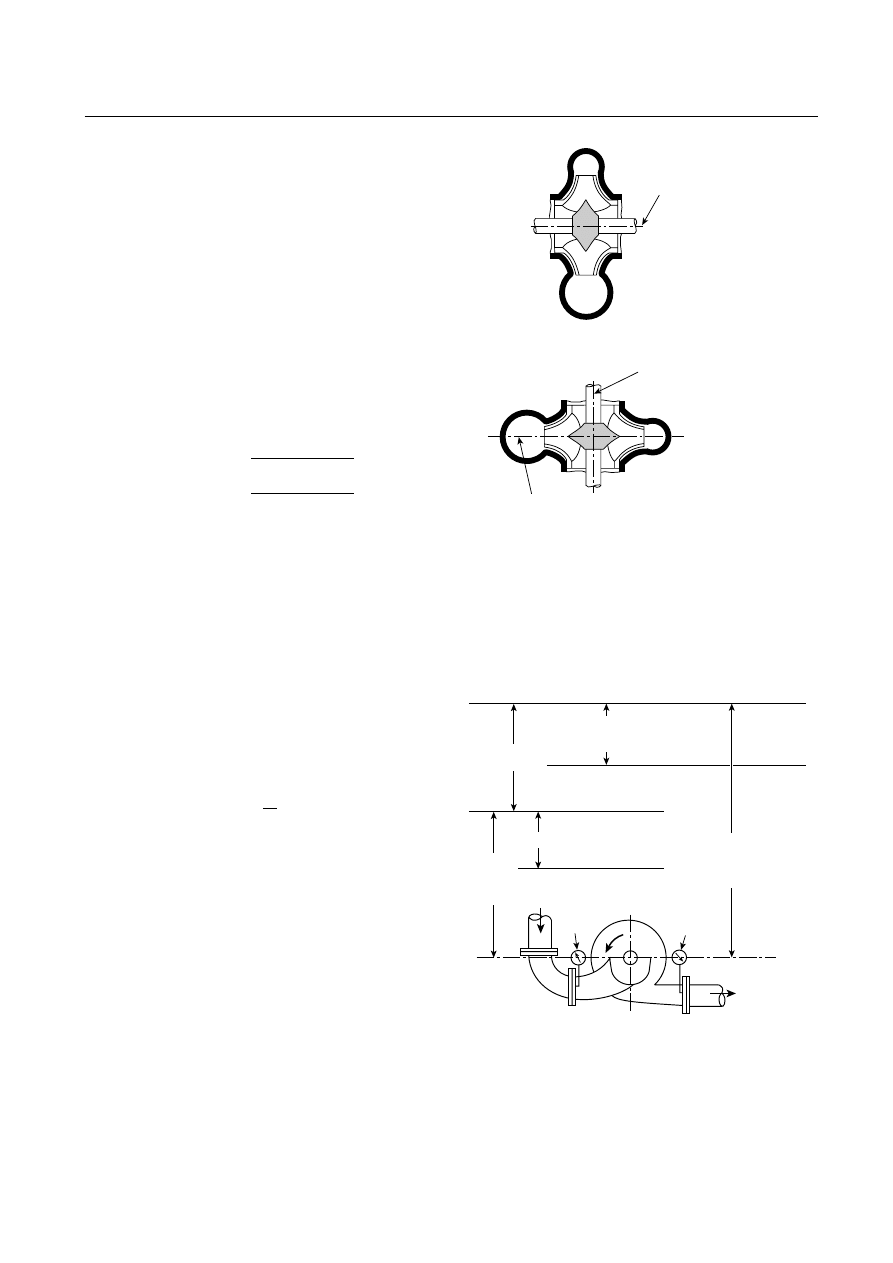
chief; fire marshal; chief of a fire prevention bureau, labor de-
partment, or health department; building official; electrical in-
spector; or others having statutory authority. For insurance pur-
poses, an insurance inspection department, rating bureau, or
other insurance company representative may be the authority
having jurisdiction. In many circumstances, the property owner
or his or her designated agent assumes the role of the authority
having jurisdiction; at government installations, the command-
ing officer or departmental official may be the authority having
jurisdiction.
A.3.2.3 Listed.
The means for identifying listed equipment may
vary for each organization concerned with product evaluation; some
organizations do not recognize equipment as listed unless it is also
labeled. The authority having jurisdiction should utilize the system
employed by the listing organization to identify a listed product.
A.3.3.18 Head.
The unit for measuring head is the meter
(foot). The relation between a pressure expressed in bar
(pounds per square inch) and a pressure expressed in meters
(feet) of head is expressed by the following formulas:
Head in meters
Pressure in bar
0.098 specific gravity
Head i
=
n
n feet
Pressure in psi
0.433 specific gravity
=
In terms of meter-kilograms (foot-pounds) of energy per
kilogram (pound) of water, all head quantities have the di-
mensions of meters (feet) of water. All pressure readings are
converted into meters (feet) of the water being pumped. (See
Figure A.3.3.18.)
A.3.3.32 Service.
For more information, see NFPA 70, National
Electrical Code, Article 100.
A.3.3.33 Service Equipment.
For more information, see
NFPA 70, National Electrical Code, Article 100.
A.3.3.39 Total Head (H ), Horizontal Pumps.
See Figure
A.3.3.39. (Figure does not show the various types of pumps
applicable.)
A.3.3.40 Total Head (H ), Vertical Turbine Pumps.
See Figure
A.3.3.40.
A.3.3.46 Velocity Head (h
v
).
Velocity head is expressed by the
following formula:
h
v
g
v
=
2
2
where:
v = velocity in the pipe in meters per second (feet
per second)
g = the acceleration due to gravity, which is
9.807 m/sec
2
(32.17 ft/sec
2
) at sea level and
45 degrees latitude
A.5.2
Because of the unique nature of fire pump units, the
approval should be obtained prior to the assembly of any spe-
cific component.
A.5.4.1
A single entity should be designated as having unit
responsibility for the pump, driver, controller, transfer switch
equipment, and accessories. Unit responsibility means the ac-
countability to answer and resolve any and all problems re-
garding the proper installation, compatibility, performance,
and acceptance of the equipment. Unit responsibility should
not be construed to mean purchase of all components from a
single supplier.
Pump shaft centerline
and datum elevation
Horizontal doub le-suction pump
Pump centerline
First-stage volute
C
L
Datum elevation
V ertical doub le-suction pump
Notes:
1. For all types of horiz ontal shaft pumps (single-stage
double-suction pump shown). Datum is same for multistage,
single- (end) suction ANSI-type or any pump with a horiz ontal
shaft.
2. For all types of vertical shaft pumps (single-stage vertical
double-suction pump shown). Datum is same for single- (end)
suction, in-line, or any pump with a vertical shaft.
FIGURE A.3.3.18 Datum Elevation of Two Stationary Pump
Designs.
Datum
h
v
(discharge)
(velocity
head)
H
(total head)
h
v
(suction) (velocity head)
W ater level
equivalent to
suction gauge
reading
Suction
gauge
Discharge
gauge
Note: Installation with suction head above atmospheric pressure shown.
h
d
(total
discharge
head)
W ater level
equivalent to
discharge
gauge reading
h
s
(total
suction
head)
FIGURE A.3.3.39 Total Head of all Types of Stationary (Not
Vertical Turbine–Type) Fire Pumps.
20
–48
INSTALLATION OF STATIONARY PUMPS FOR FIRE PROTECTION
2003 Edition
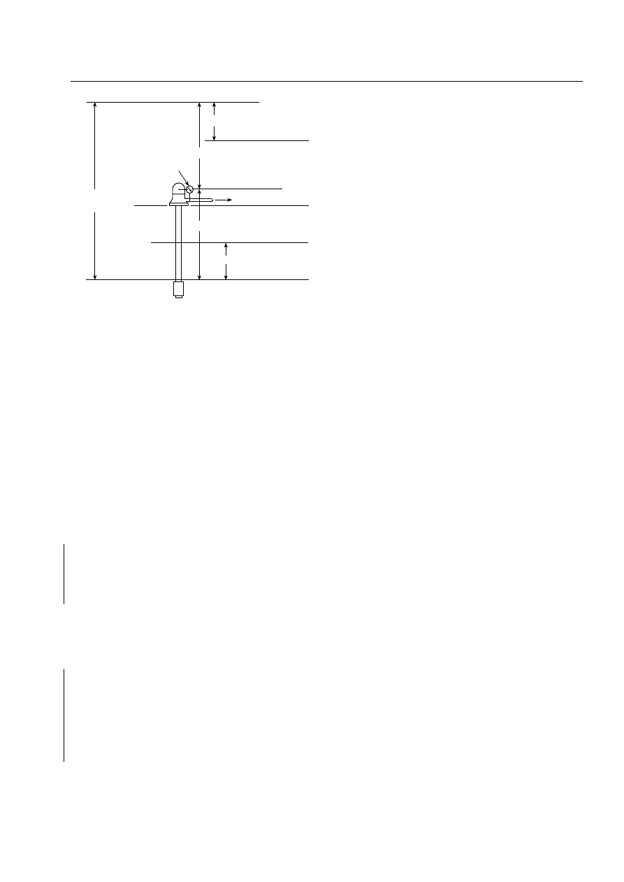
A.5.6.1
For water supply capacity and pressure requirements,
see the following documents:
(1) NFPA 13, Standard for the Installation of Sprinkler Systems
(2) NFPA 14, Standard for the Installation of Standpipe and Hose
Systems
(3) NFPA 15, Standard for Water Spray Fixed Systems for Fire Protection
(4) NFPA 16, Standard for the Installation of Foam-Water Sprinkler
and Foam-Water Spray Systems
(5) NFPA 24, Standard for the Installation of Private Fire Service
Mains and Their Appurtenances
A.5.6.2
Where the suction supply is from a factory-use water
system, pump operation at 150 percent of rated capacity should
not create hazardous process upsets due to low water pressure.
A.5.6.4
Water sources containing salt or other materials del-
eterious to the fire protection systems should be avoided.
A.5.7.1
This section does not preclude the use of pumps in
public and private water supplies that provide water for domestic,
process, and fire protection purposes. Such pumps are not fire
pumps and are not expected to meet all of the requirements of
NFPA 20. Such pumps are permitted for fire protection if they are
considered reliable by the analysis mandated in 5.7.1.
A.5.7.4
It is poor design practice to overdesign the fire pump
and driver and then count on the pressure relief valve to open
and relieve the excess pressure. A pressure relief valve is not an
acceptable method of reducing system pressure under normal
operating conditions and should not be used as such.
A.5.8
The performance of the pump when applied at ca-
pacities over 140 percent of rated capacity can be adversely
affected by the suction conditions. Application of the pump
at capacities less than 90 percent of the rated capacity is not
recommended.
The selection and application of the fire pump should not be
confused with pump operating conditions. With proper suction
conditions, the pump can operate at any point on its characteris-
tic curve from shutoff to 150 percent of its rated capacity.
A.5.8.2
In countries utilizing the metric system, there do not
appear to be standardized flow ratings for pump capacities;
therefore, a soft metric conversion is utilized.
A.5.10.2
For protection against damage from overpressure,
where desired, a gauge protector should be installed.
A.5.12
Special consideration needs to be given to fire pump
installations installed below grade. Light, heat, drainage, and
ventilation are several of the variables that need to be ad-
dressed. Some locations or installations may not require a
pump house. Where a pump room or pump house is required,
it should be of ample size and located to permit short and
properly arranged piping. The suction piping should receive
first consideration. The pump house should preferably be a
detached building of noncombustible construction. A one-
story pump room with a combustible roof, either detached or
well cut off from an adjoining one-story building, is acceptable
if sprinklered. Where a detached building is not feasible, the
pump room should be located and constructed so as to pro-
tect the pump unit and controls from falling floors or machin-
ery and from fire that could drive away the pump operator or
damage the pump unit or controls. Access to the pump room
should be provided from outside the building. Where the use
of brick or reinforced concrete is not feasible, metal lath and
plaster is recommended for the construction of the pump
room. The pump room or pump house should not be used for
storage purposes. Vertical shaft turbine–type pumps might ne-
cessitate a removable panel in the pump house roof to permit
the pump to be removed for inspection or repair. Proper
clearances to equipment should be provided as recom-
mended by the manufacturer’s drawings.
A.5.12.1
A fire pump that is inoperative for any reason at any
time constitutes an impairment to the fire protection system.
It should be returned to service without delay.
Rain and intense heat from the sun are adverse conditions
to equipment not installed in a completely protective enclo-
sure. At a minimum, equipment installed outdoors should be
shielded by a roof or deck.
A.5.12.6
Pump rooms and pump houses should be dry and
free of condensate. To accomplish a dry environment, heat
might be necessary.
A.5.13.1
The exterior of aboveground steel piping should be
kept painted.
A.5.13.2
Flanges welded to pipe are preferred.
A.5.13.4
When welding is performed on the pump suction or
discharge piping with the pump in place, the welding ground
should be on the same side of the pump as the welding.
A.5.14.1
The exterior of steel suction piping should be kept
painted.
Buried iron or steel pipe should be lined and coated or
protected against corrosion in conformance with AWWA
C104, Cement-Mortar L ining for Cast-Iron and D uctile-Iron Pipe
and Fittings for Water, or equivalent standards.
A.5.14.4
The following notes apply to Figure A.5.14.4:
(1) A jockey pump is usually required with automatically con-
trolled pumps.
(2) If testing facilities are to be provided, also see Figure
A.5.19.1.2(a) and Figure A.5.19.1.2(b).
(3) Pressure-sensing lines also need to be installed in accor-
dance with 10.5.2.1 or 12.5.2.1. See Figure A.10.5.2.1(a)
and Figure A.10.5.2.1(b).
h
d
(total discharge head)
h
v
(discharge) (velocity head)
Discharge
gauge
H
(total head)
Datum
Ground level
Drawdown
Static water level
h
(vertical distance, datum to
pumping water level)
Pumping water level
Water level
equivalent to
suction gauge
reading
FIGURE A.3.3.40 Total Head of Vertical Turbine–Type Fire
Pumps.
20
–49
ANNEX A
2003 Edition
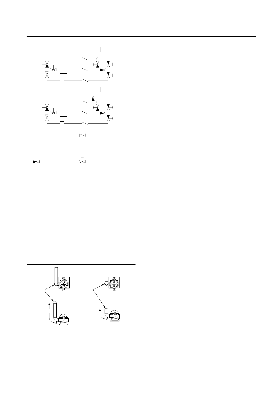
A.5.14.5
Where the suction supply is from public water mains,
the gate valve should be located as far as is practical from the
suction flange on the pump. Where it comes from a stored water
container, the gate valve should be located at the outlet of the
container. A butterfly valve on the suction side of the pump can
create turbulence that adversely affects the pump performance
and can increase the possibility of blockage of the pipe.
A.5.14.6
See Figure A.5.14.6. (See Hydraulics Institute Stan-
dards for Centrifugal, Rotary and Reciprocating Pumps for addi-
tional information.)
A.5.14.8
When selecting screen material, consideration
should be given to prevention of fouling from aquatic growth.
Antifouling is best accomplished with brass or copper wire.
A.5.14.9
The term device as used in this subsection is intended to
include, but not be limited to, devices that sense suction pressure
and then restrict or stop the fire pump discharge. Due to the
pressure losses and the potential for interruption of the flow to
the fire protection systems, the use of backflow prevention de-
vices is discouraged in fire pump piping. Where required, how-
ever, the placement of such a device on the discharge side of the
pump is to ensure acceptable flow characteristics to the pump
suction. It is more efficient to lose the pressure after the pump
has boosted it, rather than before the pump has boosted it.
Where the backflow preventer is on the discharge side of the
pump and a jockey pump is installed, the jockey pump discharge
and sensing lines need to be located so that a cross-connection is
not created through the jockey pump.
A.5.14.10
For more information, see the Hydraulics Institute
Standards for Centrifugal, Rotary and Reciprocating Pumps.
A.5.15.3
Flanges welded to the pipe are preferred.
A.5.15.5
The discharge pipe size should be such that, with the
pump(s) operating at 150 percent of rated capacity, the velocity
in the discharge pipe does not exceed 6.2 m/sec (20 ft/sec).
A.5.15.6
Large fire protection systems sometimes experience
severe water hammer caused by backflow when the automatic
control shuts down the fire pump. Where conditions can be
expected to cause objectionable water hammer, a listed anti-
water-hammer check valve should be installed in the discharge
line of the fire pump. Automatically controlled pumps in tall
buildings could give trouble from water hammer as the pump
is shutting down.
Where a backflow preventer is substituted for the discharge
check valve, an additional backflow preventer might be necessary
in the bypass piping to prevent backflow through the bypass.
Where a backflow preventer is substituted for the discharge
check valve, the connection for the sensing line is permitted to
be between the last check valve and the last control valve if the
pressure-sensing line connection can be made without alter-
ing the backflow valve or violating its listing. This method can
sometimes be done by adding a connection through the test
port on the backflow valve. In this situation, the discharge con-
trol valve is not necessary, since the last control valve on the
backflow preventer serves this function.
Where a backflow preventer is substituted for the discharge
check valve and the connection of the sensing line cannot be
made within the backflow preventer, the sensing line should
be connected between the backflow preventer and the pump’s
discharge control valve. In this situation, the backflow preven-
ter cannot substitute for the discharge control valve because
the sensing line must be able to be isolated.
A.5.16
Isolation valves and control valves are considered to
be identical when used in conjunction with a backflow preven-
tion assembly.
A.5.17
Pipe breakage caused by movement can be greatly
lessened and, in many cases, prevented by increasing flexibil-
ity between major parts of the piping. One part of the piping
should never be held rigidly and another free to move, with-
out provisions for relieving the strain. Flexibility can be pro-
vided by the use of flexible couplings at critical points and by
allowing clearances at walls and floors. Fire pump suction and
discharge pipes should be treated the same as sprinkler risers
for whatever portion is within a building. (See NFPA 13.)
F
J
J
Header used only
for testing
To
system
From
supply
From
supply
To
system
Header used as a
hydrant or for testing
Fire pump
Jockey pump
OS&Y gate valve
or indicating butterfly
valve
OS&Y gate valve
Hose header
Check valve
FIGURE A.5.14.4 Schematic Diagram of Suggested Arrange-
ments for a Fire Pump with a Bypass, Taking Suction from
Public Mains.
PLAN VIEW
ELEVATION VIEW
Right
ELEVATION VIEW
Wrong
PLAN VIEW
x
> 10 × diam.
x
≤ 10 × diam.
Suction
pipe
Suction
pipe
FIGURE A.5.14.6 Right and Wrong Pump Suctions.
20
–50
INSTALLATION OF STATIONARY PUMPS FOR FIRE PROTECTION
2003 Edition
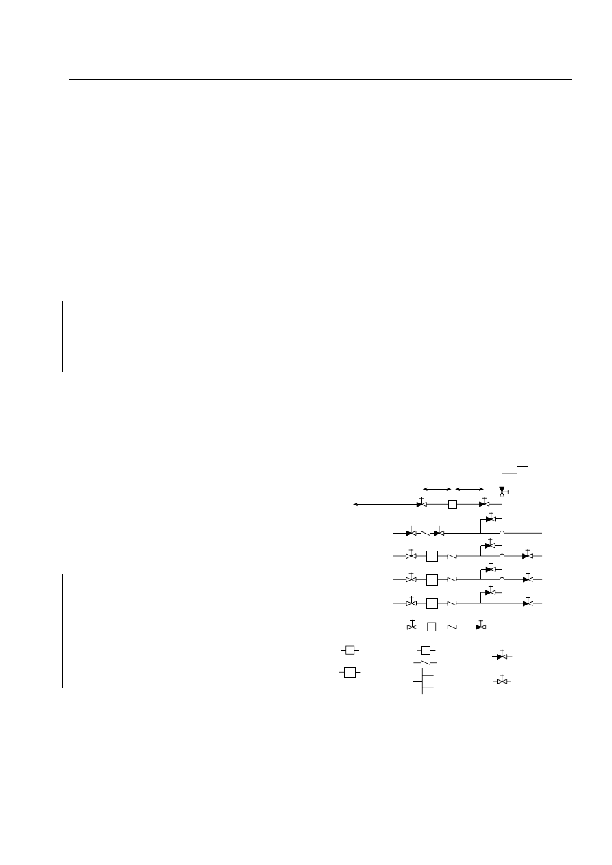
Holes through pump room fire walls should be packed
with mineral wool or other suitable material held in place by
pipe collars on each side of the wall. Pipes passing through
foundation walls or pit walls into ground should have clear-
ance from these walls, but holes should be watertight. Space
around pipes passing through pump room walls or pump
house floors can be filled with asphalt mastic.
A.5.18.1
The pressure is required to be evaluated at 121 per-
cent of the net rated shutoff pressure because the pressure is
proportional to the square of the speed that the pump is
turned. A diesel engine governor is required to be capable of
limiting the maximum engine speed to 110 percent, creating a
pressure of 121 percent. Since the only time that a pressure
relief valve is required by the standard to be installed is where
the diesel engine is turning faster than normal, and since this
is a relatively rare event, it is permitted for the discharge from
the pressure relief valve to be piped back to the suction side of
the pump.
A.5.18.1.2
In situations where the required system pressure
is close to the pressure rating of the system components and
the water supply pressure varies significantly over time, it
might be necessary to use a tank between the water supply
and the pump suction control valve, in lieu of a direct con-
nection to the water supply piping, to eliminate system over-
pressurization.
A.5.18.5
The relief valve cone should be piped to a point
where water can be freely discharged, preferably outside the
building. If the relief valve discharge pipe is connected to an
underground drain, care should be taken that no steam drains
enter near enough to work back through the cone and into
the pump room.
A.5.18.7
Where the relief valve discharges back to the source
of supply, the back pressure capabilities and limitations of the
valve to be used should be determined. It might be necessary
to increase the size of the relief valve and piping above the
minimum to obtain adequate relief capacity due to back pres-
sure restriction.
A.5.18.8
When discharge enters the reservoir below mini-
mum water level, there is not likely to be an air problem. If
it enters over the top of the reservoir, the air problem is
reduced by extending the discharge to below the normal
water level.
A.5.19.1.1
The two objectives of running a pump test are to
make sure that the pump itself is still functioning properly and
to make sure that the water supply can still deliver the correct
amount of water to the pump at the correct pressure. Some
arrangements of test equipment do not permit the water sup-
ply to be tested. Every fire pump installation needs to have at
least one arrangement of test equipment where the water sup-
ply can be tested. Inspection, testing, and maintenance stan-
dards (NFPA 25) require the pump test to be run at least once
every three years using a method that tests the water supply’s
ability to provide water to the pump.
A.5.19.1.2
Outlets can be provided through the use of stan-
dard test headers, yard hydrants, wall hydrants, or standpipe
hose valves.
The following notes apply to Figure A.5.19.1.2(a) and
Figure A.5.19.1.2(b):
(1) Distance as recommended by the meter manufacturer.
(2) Distance not less than 5 diameters of suction pipe for
top or bottom suction connection. Distance not less
than 10 diameters of suction pipe for side connection
(not recommended).
(3) Automatic air release if piping forms an inverted “U,”
trapping air.
(4) The fire protection system should have outlets available
to test the fire pump and suction supply piping. (See
A.5.19.3.1.)
(5) The closed loop meter arrangement will test only net
pump performance. It does not test the condition of the
suction supply, valves, piping, and so forth.
(6) Return piping should be so arranged that no air can be
trapped that would eventually end up in the eye of the
pump impeller.
(7) Turbulence in the water entering the pump should be
avoided to eliminate cavitation, which would reduce
pump discharge and damage the pump impeller. For
this reason, side connection is not recommended.
(8) Prolonged recirculation can cause damaging heat
buildup, unless some water is wasted.
(9) Flowmeter should be installed according to manufactur-
er’s instructions.
(10) Pressure-sensing lines also need to be installed in ac-
cordance with 10.5.2.1. [See Figure A.10.5.2.1(a) and
Figure A.10.5.2.1(b).]
A.5.19.2.1.1
Metering devices should discharge to drain.
In the case of a limited water supply, the discharge should
be back to the water source (e.g., suction tank, small pond). If
this discharge enters the source below minimum water level, it
is not likely to create an air problem for the pump suction. If it
enters over the top of the source, the air problem is reduced
by extending the discharge to below the normal water level.
See Note 1
See Note 1
M
FP
FP
FP
J
M
FP
Bypass (if
of value)
See
Note 5
To drain or
pump water
source
From supply
From supply
From supply
From supply
Hose header
(if needed for
hose streams)
To system
To system
To system
To system
To system
Flowmeter
Fire pump
Jockey pump
Check valve
Hose header
OS&Y gate
valve or indicating
butterfly valve
OS&Y
gate valve
J
FIGURE A.5.19.1.2(a) Preferred Arrangement for Measur-
ing Fire Pump Water Flow with Meter for Multiple Pumps and
Water Supplies. Water is permitted to discharge to a drain or to
the fire pump water source.
20
–51
ANNEX A
2003 Edition
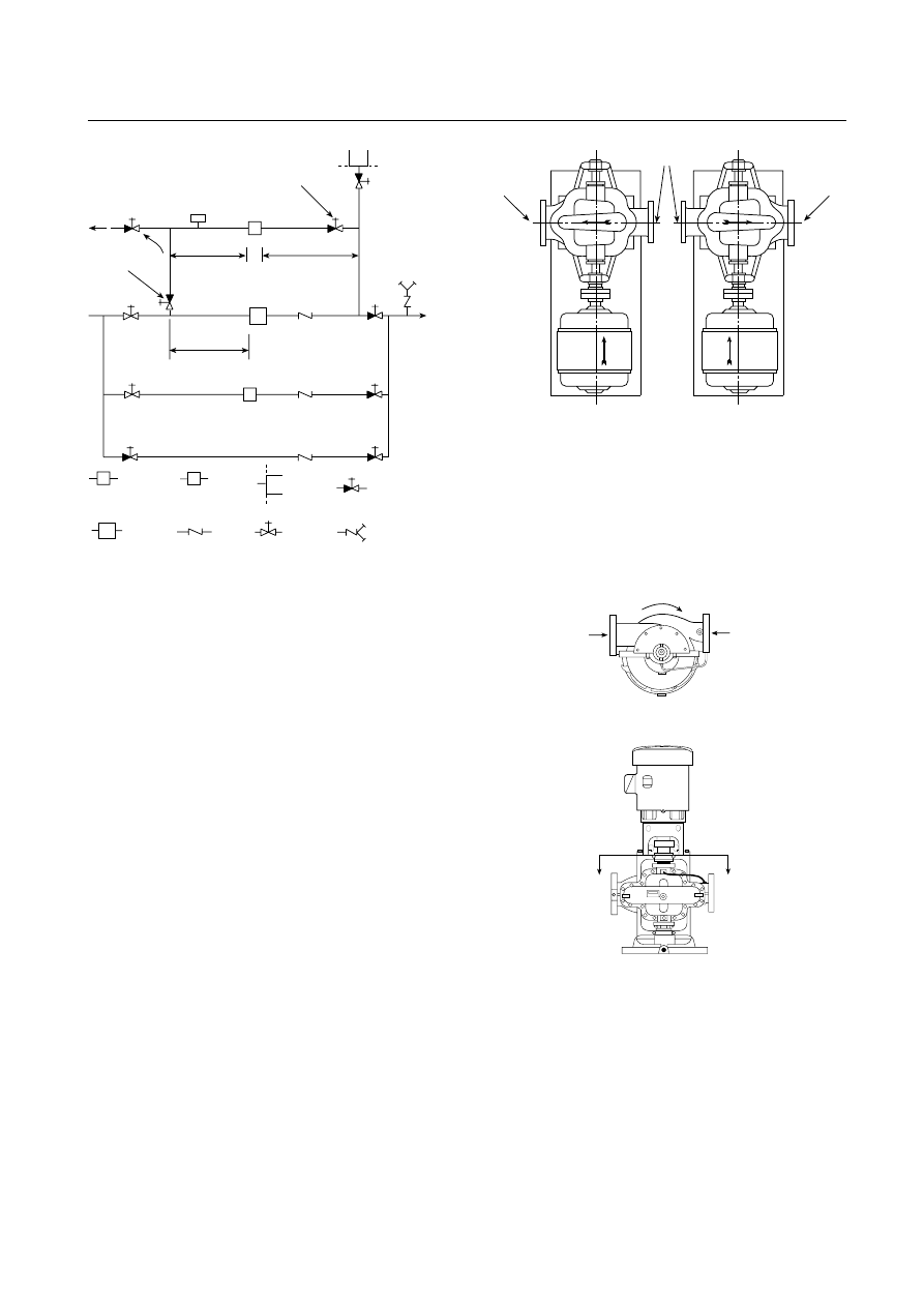
A.5.19.3.1
The hose valves should be attached to a header or
manifold and connected by suitable piping to the pump dis-
charge piping. The connection point should be between the
discharge check valve and the discharge gate valve. Hose
valves should be located to avoid any possible water damage to
the pump driver or controller, and they should be outside the
pump room or pump house. If there are other adequate
pump testing facilities, the hose valve header can be omitted
when its main function is to provide a method of pump and
suction supply testing. Where the hose header also serves as
the equivalent of a yard hydrant, this omission should not re-
duce the number of hose valves to less than two.
A.5.22
Pumps are designated as having right-hand, or clock-
wise (CW), rotation or left-hand, or counterclockwise (CCW),
rotation. Diesel engines are commonly stocked and supplied
with clockwise rotation.
Pump shaft rotation can be determined as follows:
(1) Horizontal Pump Shaft Rotation. The rotation of a horizon-
tal pump can be determined by standing at the driver end
and facing the pump. [See Figure A.5.22(a).] If the top of
the shaft revolves from the left to the right, the rotation is
right-handed, or clockwise (CW). If the top of the shaft
revolves from right to left, the rotation is left-handed, or
counterclockwise (CCW).
(2) V ertical Pump Shaft Rotation. The rotation of a vertical
pump can be determined by looking down on the top of
the pump. If the point of the shaft directly opposite re-
volves from left to right, the rotation is right-handed, or
clockwise (CW). [See Figure A.5.22(b).] If the point of the
shaft directly opposite revolves from right to left, the rota-
tion is left-handed, or counterclockwise (CCW).
M
FP
Hose header
See
Note 4
See Note 1
Meter throttle
valve
From
supply
Fire department
connection
(see NFPA 13
and NFPA 14)
See Note 2
To
system
Bypass (if of value)
J
M
FP
Flowmeter
Fire
pump
Jockey
pump
Check
valve
Hose
header
OS&Y gate
valve or
indicating
butterfly valve
OS&Y
gate valve
Fire department
connection
J
See
Note 3
See Note 1
Meter control
valve
FIGURE A.5.19.1.2(b) Typical Arrangement for Measuring
Fire Pump Water Flow with Meter. Discharge from the flowme-
ter is recirculated to the fire pump suction line.
Suction
Discharge
Suction
Diesel
engines
available in
this rotation
Some
diesels
available in
this rotation
at no extra
cost
Counterclockwise rotation
when viewed from
driver end
Clockwise rotation
when viewed from
driver end
FIGURE A.5.22(a) Horizontal Pump Shaft Rotation.
Clockwise rotation
Suction
Discharge
Section A-A
TOP VIEW
A
A
SIDE VIEW
FIGURE A.5.22(b) Vertical Pump Shaft Rotation.
20
–52
INSTALLATION OF STATIONARY PUMPS FOR FIRE PROTECTION
2003 Edition
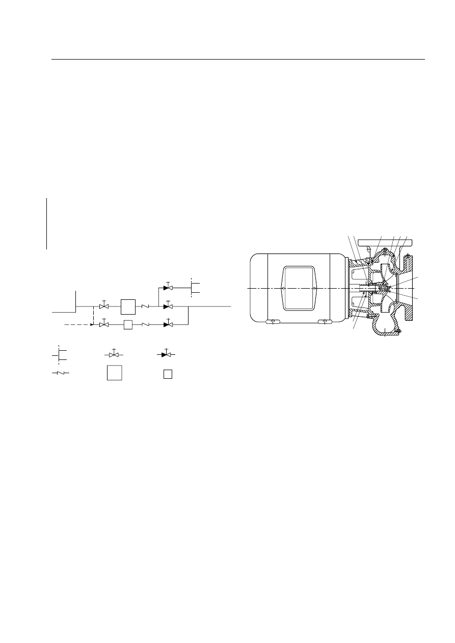
A.5.23
In addition to those conditions that require alarm sig-
nals for pump controllers and engines, there are other condi-
tions for which such alarms might be recommended, depending
upon local conditions. Some of these supervisory alarm condi-
tions are as follows:
(1) Low pump room temperature
(2) Relief valve discharge
(3) Flowmeter left on, bypassing the pump
(4) Water level in suction supply below normal
(5) Water level in suction supply near depletion
(6) Diesel fuel supply below normal
(7) Steam pressure below normal
Such additional alarms can be incorporated into the
trouble alarms already provided on the controller, or they can
be independent.
A.5.24
Pressure maintenance (jockey or make-up) pumps
should be used where it is desirable to maintain a uniform or
relatively high pressure on the fire protection system. A jockey
pump should be sized to make up the allowable leakage rate
within 10 minutes or 3.8 L/min (1 gpm), whichever is larger.
A domestic water pump in a dual-purpose water supply sys-
tem can function as a means of maintaining pressure.
A.5.24.4
See Figure A.5.24.4.
A.5.24.5
A centrifugal-type pressure maintenance pump is
preferable.
The following notes apply to a centrifugal-type pressure
maintenance pump:
(1) A jockey pump is usually required with automatically con-
trolled pumps.
(2) Jockey pump suction can come from the tank filling sup-
ply line. This situation would allow high pressure to be
maintained on the fire protection system even when the
supply tank is empty for repairs.
(3) Pressure-sensing lines also need to be installed in accor-
dance with 10.5.2.1. [See Figure A.10.5.2.1(a) and Figure
A.10.5.2.1(b).]
A.5.27.1
NFPA 13, Standard for the Installation of Sprinkler Sys-
tems, contains specific guidance for seismic design of fire pro-
tection systems. Tables are available to determine the relative
strength of many common bracing materials and fasteners.
A.6.1.1
See Figure A.6.1.1(a) through Figure A.6.1.1(h).
F
From tank or
tank fill line
Hose
header
Check valve
OS&Y
gate valve
OS&Y gate valve
or indicating butterfly
valve
J
J
Jockey pump
Fire pump
F
FIGURE A.5.24.4 Jockey Pump Installation with Fire Pump.
14
40
69
26
2
1
32
73
71 6
32 K ey, impeller
40 Deflector
69 Lockwasher
71 Adapter
73 Gasket
1 Casing
2 Impeller
6 Shaft
14 Sleeve, shaft
26 Screw, impeller
FIGURE A.6.1.1(a) Overhung Impeller — Close Coupled
Single Stage — End Suction.
20
–53
ANNEX A
2003 Edition
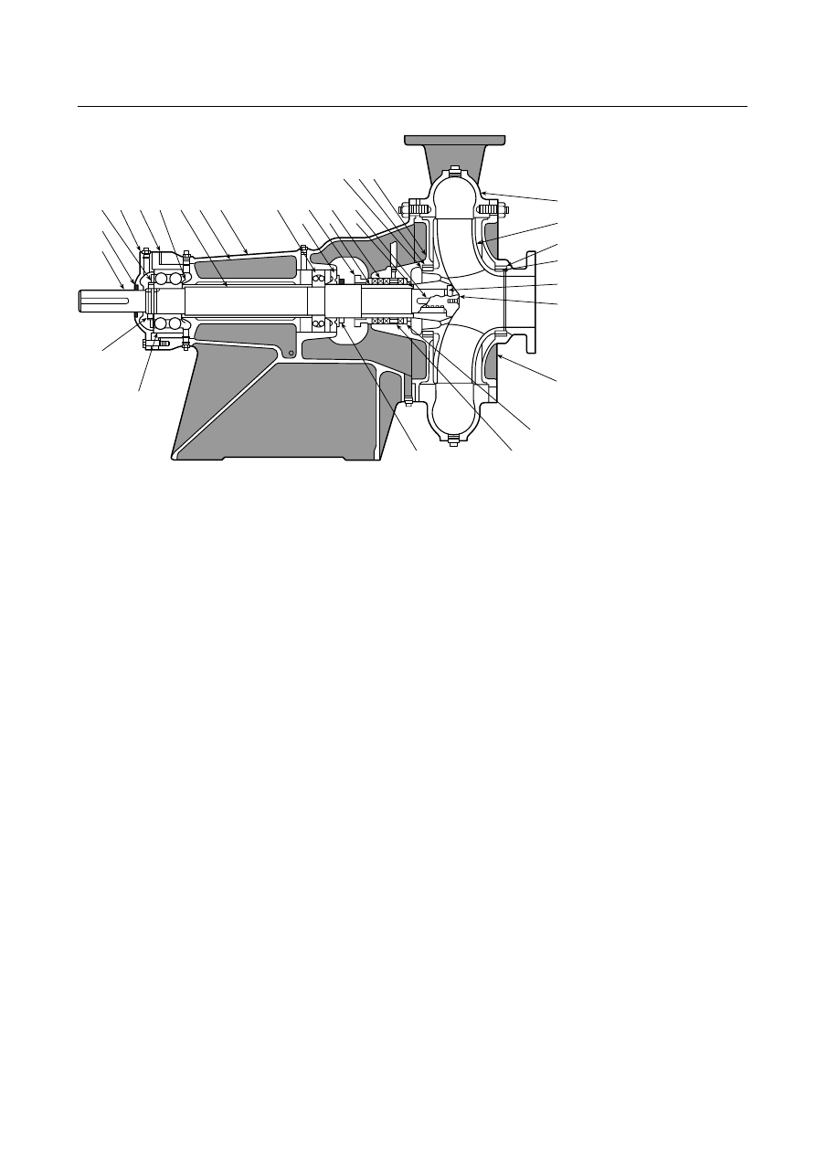
9
63
29
40
18
22
6
49
69 37 67 62 78 21 19
16
51
17
14
13
38
32
8 27 11
25
8
28
26
2
1
1 Casing
2 Impeller
6 Shaft, pump
8 Ring, impeller
9 Cover, suction
11 Cover, stuffing-box
13 Packing
14 Sleeve, shaft
16 Bearing, inboard
17 Gland
18 Bearing, outboard
19 Frame
21 Liner, frame
22 Locknut, bearing
25 Ring, suction cover
26 Screw, impeller
27 Ring, stuffing-box
cover
28 Gasket
29 Ring, lantern
32 Key, impeller
37 Cover, bearing, outboard
38 Gasket, shaft sleeve
40 Deflector
49 Seal, bearing cover,
outboard
51 Retainer, grease
62 Thrower (oil or grease)
63 Busing, stuffing-box
67 Shim, frame liner
69 Lockwasher
78 Spacer, bearing
FIGURE A.6.1.1(b) Overhung Impeller — Separately Coupled Single Stage — Frame Mounted.
20
–54
INSTALLATION OF STATIONARY PUMPS FOR FIRE PROTECTION
2003 Edition
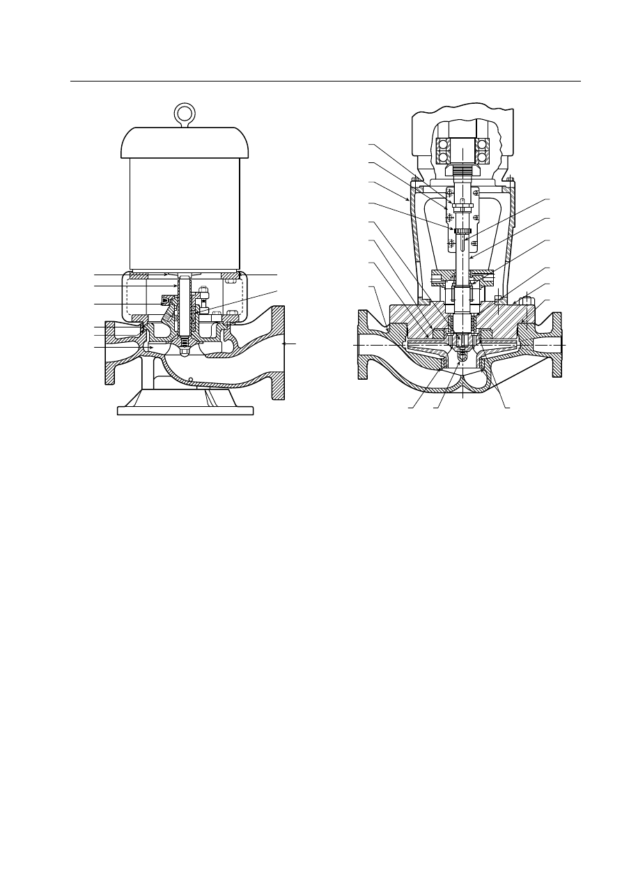
40
14
17
11
73
2
71
13
1
1 Casing
2 Impeller
11 Cover, seal chamber
13 Packing
14 Sleeve, shaft
17 Gland, packing
40 Deflector
71 Adapter
73 Gasket, casing
FIGURE A.6.1.1(c) Overhung Impeller — Close Coupled
Single Stage — In-Line (Showing Seal and Packaging).
86
70
81
66
32
27
2
1
11
89
6
46
11
73
8
24
25
1 Casing
2 Impeller
6 Shaft, pump
7 Ring, casing
8 Ring, impeller
11 Cover, seal chamber
24 Nut, impeller
27 Ring, stuffing-box cover
32 Key, impeller
46 Key, coupling
66 Nut, shaft adjusting
70 Coupling, shaft
73 Gasket
81 Pedestal, driver
86 Ring, thrust, split
89 Seal
117 Bushing, pressure
reducing
FIGURE A.6.1.1(d)
Overhung Impeller — Separately
Coupled Single Stage — In-Line — Rigid Coupling.
20
–55
ANNEX A
2003 Edition
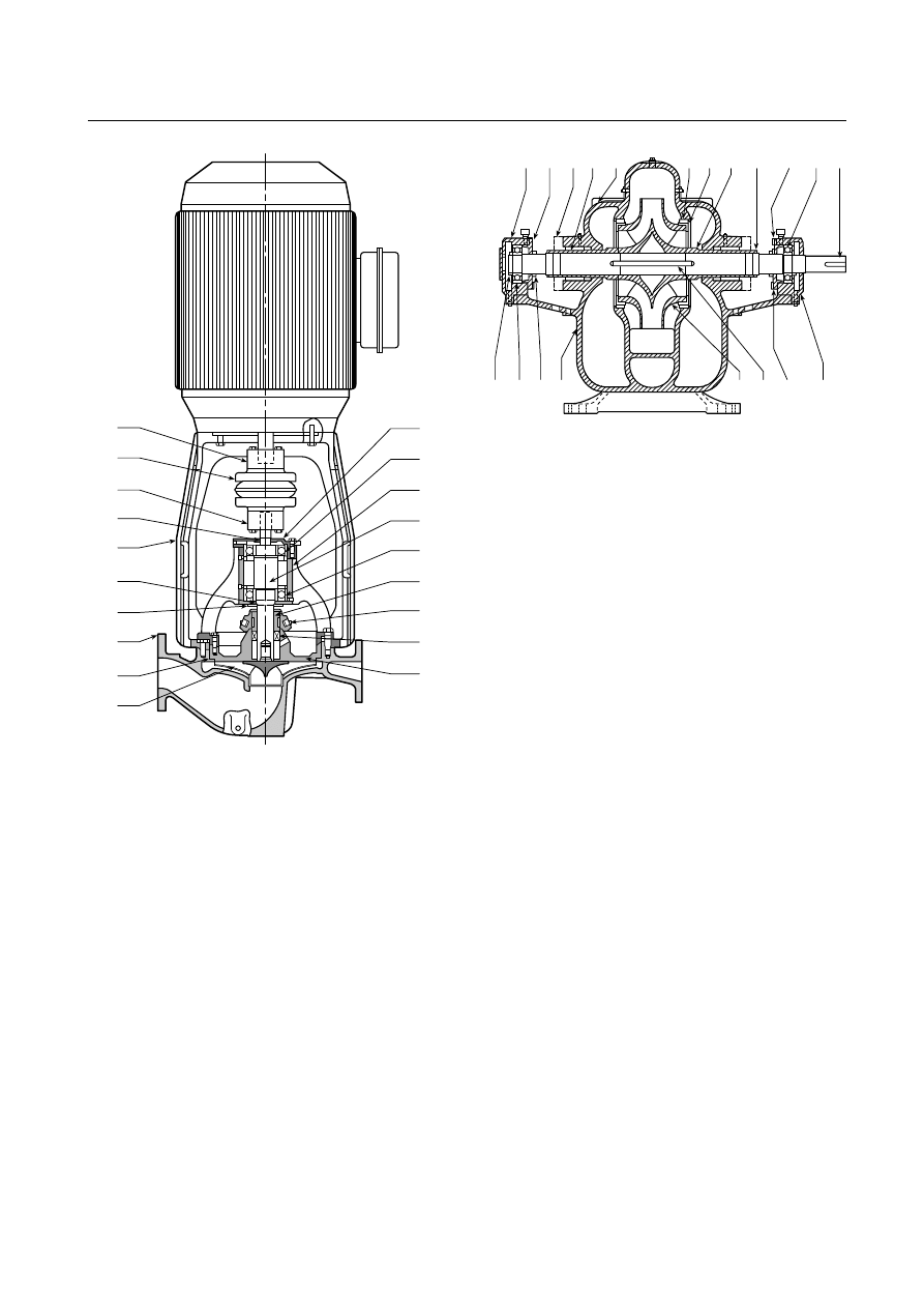
73
2
1
40
47
81
49
44
88
42
33
18
99
6
16
14
17
89
11
1 Casing
2 Impeller
6 Shaft, pump
11 Cover, seal chamber
14 Sleeve, shaft
16 Bearing, inboard
17 Gland
18 Bearing, outboard
33 Cap, bearing, outboard
40 Deflector
42 Coupling half, driver
44 Coupling half, pump
47 Seal, bearing cover, inboard
49 Seal, bearing cover, outboard
73 Gasket
81 Pedestal, driver
88 Spacer, coupling
89 Seal
99 Housing, bearing
FIGURE A.6.1.1(e)
Overhung Impeller — Separately
Coupled Single Stage — In-Line — Flexible Coupling.
33
37
65 80 1B
7
8
14
20
35
16
6
22
18 40 1A
2
32
40
31
1A Casing, lower half
1B Casing, upper half
2 Impeller
6 Shaft
7 Ring, casing
8 Ring, impeller
14 Sleeve, shaft
16 Bearing, inboard
18 Bearing, outboard
20 Nut, shaft sleeve
22 Locknut
31 Housing, bearing inboard
32 Key, impeller
33 Housing, bearing outboard
35 Cover, bearing inboard
37 Cover, bearing outboard
40 Deflector
65 Seal, mechanical stationary
element
80 Seal, mechanical rotating element
FIGURE A.6.1.1(f) Impeller Between Bearings — Separately
Coupled — Single Stage — Axial (Horizontal) Split Case.
20
–56
INSTALLATION OF STATIONARY PUMPS FOR FIRE PROTECTION
2003 Edition
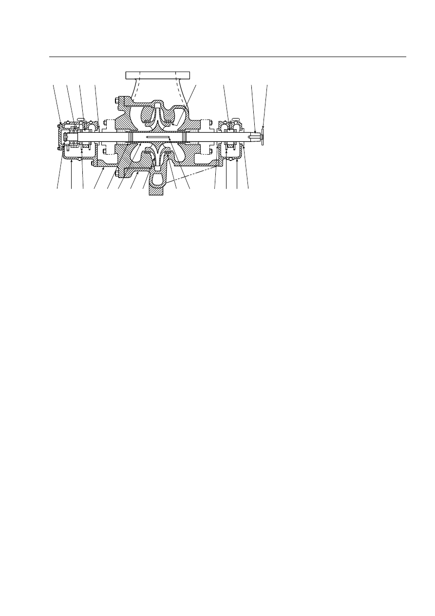
18B
37
18A
40
8
16
6
50
40
31
60
40
32
7
2
1
14
20
11
60
33
22
33 Housing, bearing, outboard
37 Cover, bearing, outboard
40 Deflector
50 Locknut, coupling
60 Ring, oil
1 Casing
2 Impeller
6 Shaft
7 Ring, casing
8 Ring, impeller
11 Cover, stuffing-box
14 Sleeve, shaft
16 Bearing, inboard, sleeve
18A Bearing, outboard, sleeve
18B Bearing, outboard, ball
20 Nut, shaft sleeve
22 Locknut, bearing
31 Housing, bearing, inboard
32 Key, impeller
FIGURE A.6.1.1(g) Impeller Between Bearings — Separately Coupled — Single Stage — Radial
(Vertical) Split Case.
20
–57
ANNEX A
2003 Edition
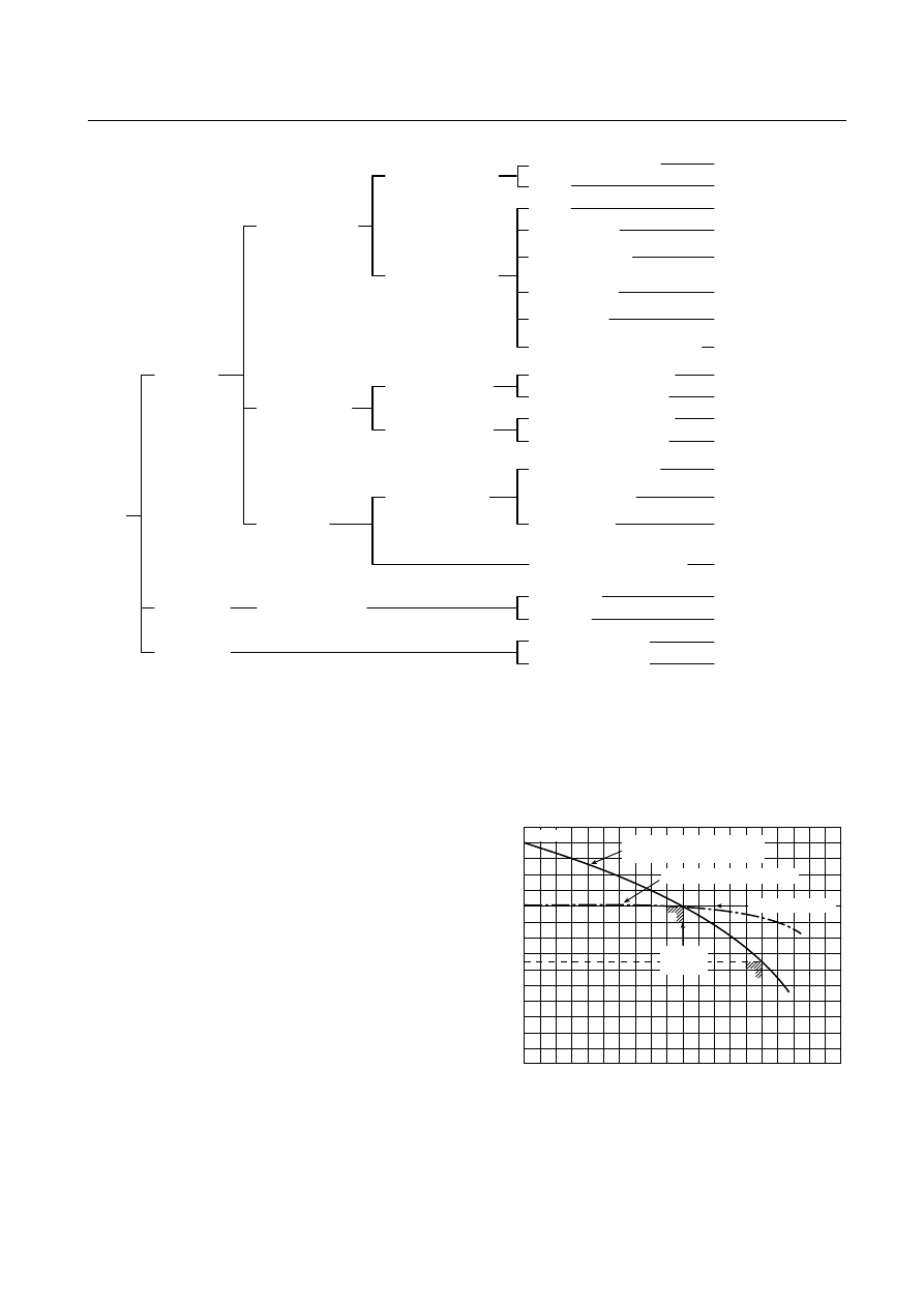
A.6.1.2
The centrifugal pump is particularly suited to boost
the pressure from a public or private supply or to pump from a
storage tank where there is a positive static head.
A.6.2
Listed pumps can have different head capacity curve
shapes for a given rating. Figure A.6.2 illustrates the extremes
of the curve shapes probable. Shutoff head will range from a
minimum of 101 percent to a maximum of 140 percent of
rated head. At 150 percent of rated capacity, head will range
from a minimum of 65 percent to a maximum of just below
rated head. Pump manufacturers can supply expected curves
for their listed pumps.
A.6.3.1
See Figure A.6.3.1.
A.6.4.1
Flexible couplings are used to compensate for tempera-
ture changes and to permit end movement of the connected
shafts without interfering with each other.
A.6.4.4
A substantial foundation is important in maintaining
alignment. The foundation preferably should be made of re-
inforced concrete.
Kinetic
Special effect
Impeller overhung or
between bearings
Axial flow impeller (propeller)
volute type (horizontal or vertical)
Regenerative
turbine
Centrifugal
Turbine type
Impeller between
bearings
Overhung impeller
Separately coupled,
single and two stage
Close coupled,
single and two stage
Separately coupled,
single stage
Separately coupled,
multistage
Vertical type, single
and multistage
Wet pit volute
Axial (horizontal) split case
Radial (vertical) split case
Deep well turbine
(including submersibles)
Barrel or can pump
Short setting or
close coupled
Axial flow impeller (propeller)
or mixed flow type (horizontal
or vertical)
Single stage
Two stage
Reversible centrifugal
Axial (horizontal) split case
Radial (vertical) split case
Rotating casing (Pitot)
Frame mounted
Centerline support
Frame mounted
In-line
In-line
End suction (including
submersibles)
Not shown
Figure A.6.1.1(a)
*
Figure A.6.1.1(c)
Figures A.6.1.1(d) and (e)
Figure A.6.1.1(b)
Not shown
Not shown
Not shown
Not shown
Figure A.6.1.1(f)
Figure A.6.1.1(g)
Not shown
Not shown
Not shown
Not shown
Not shown
Not shown
Not shown
Not shown
Not shown
Note: Kinetic pumps can be classified by such methods as impeller or casing configuration, end application of
the pump, specific speed, or mechanical configuration. The method used in this chart is based primarily
on mechanical configuration.
*Includes radial, mixed flow, and axial flow designs.
FIGURE A.6.1.1(h) Types of Stationary Pumps.
0
0
50
100
150
200
Rated
capacity
Rated total head
“Flat” head capacity curve
Head capacity curve with
steepest shape permissible
Shutoff
150
100
50
140
65
P
ercent of
rated total head
Percent of rated capacity
FIGURE A.6.2 Pump Characteristics Curves.
20
–58
INSTALLATION OF STATIONARY PUMPS FOR FIRE PROTECTION
2003 Edition
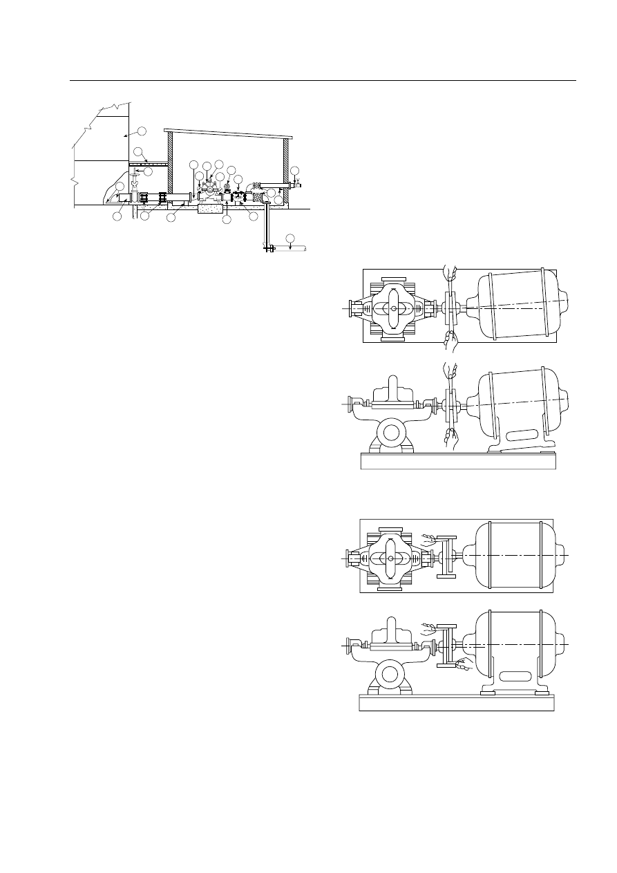
A.6.5
If the pump and driver were shipped from the factory
with both machines mounted on a common base plate, they
were accurately aligned before shipment. All base plates are
flexible to some extent and, therefore, should not be relied
upon to maintain the factory alignment. Realignment is nec-
essary after the complete unit has been leveled on the founda-
tion and again after the grout has set and foundation bolts
have been tightened. The alignment should be checked after
the unit is piped and rechecked periodically. To facilitate ac-
curate field alignment, most manufacturers either do not
dowel the pumps or drivers on the base plates before ship-
ment or, at most, dowel the pump only.
After the pump and driver unit has been placed on the
foundation, the coupling halves should be disconnected. The
coupling should not be reconnected until the alignment op-
erations have been completed.
The purpose of the flexible coupling is to compensate for
temperature changes and to permit end movement of the
shafts without interference with each other while transmitting
power from the driver to the pump.
The two forms of misalignment between the pump shaft
and the driver shaft are as follows:
(1) Angular Misalignment. Shafts with axes concentric but not
parallel
(2) Parallel Misalignment. Shafts with axes parallel but not
concentric
The faces of the coupling halves should be spaced within
the manufacturer’s recommendations and far enough apart
so that they cannot strike each other when the driver rotor is
moved hard over toward the pump. Due allowance should be
made for wear of the thrust bearings. The necessary tools for
an approximate check of the alignment of a flexible coupling
are a straight edge and a taper gauge or a set of feeler gauges.
A check for angular alignment is made by inserting the
taper gauge or feelers at four points between the coupling
faces and comparing the distance between the faces at four
points spaced at 90–degree intervals around the coupling. [See
Figure A.6.5(a).] The unit will be in angular alignment when
the measurements show that the coupling faces are the same
distance apart at all points.
A check for parallel alignment is made by placing a straight
edge across both coupling rims at the top, bottom, and both
sides. [See Figure A.6.5(b).] The unit will be in parallel align-
ment when the straight edge rests evenly on the coupling rim
at all positions.
14
10
11
12
18
9
8
7
5
13
18
19
16
17
15
3
2
4
6
1
1 Aboveground suction tank
2 Entrance elbow and square steel
vortex plate with dimensions at
least twice the diameter of the
suction pipe. Distance above the
bottom of tank is one-half the
diameter of the suction pipe with
minimum of 6 in. (152 mm).
3 Suction pipe
4 Frostproof casing
5 Flexible couplings for strain relief
6 OS&Y gate valve
(see 5.14.5 and
A.5.14.5)
7 Eccentric reducer
8 Suction gauge
9 Horizontal split-case fire pump
10 Automatic air release
11 Discharge gauge
12 Reducing discharge tee
13 Discharge check valve
14 Relief valve (if required)
15 Supply pipe for fire protection
system
16 Drain valve or ball drip
17 Hose valve manifold with
hose valves
18 Pipe supports
19 Indicating gate or indicating
butterfly valve
FIGURE A.6.3.1 Horizontal Split-Case Fire Pump Installa-
tion with Water Supply Under a Positive Head.
FIGURE A.6.5(a) Checking Angular Alignment. (Courtesy of
Hydraulics Institute Standards for Centrifugal, Rotary and Recipro-
cating Pumps.)
FIGURE A.6.5(b) Checking Parallel Alignment. (Courtesy of
Hydraulics Institute Standards for Centrifugal, Rotary and Recipro-
cating Pumps.)
20
–59
ANNEX A
2003 Edition
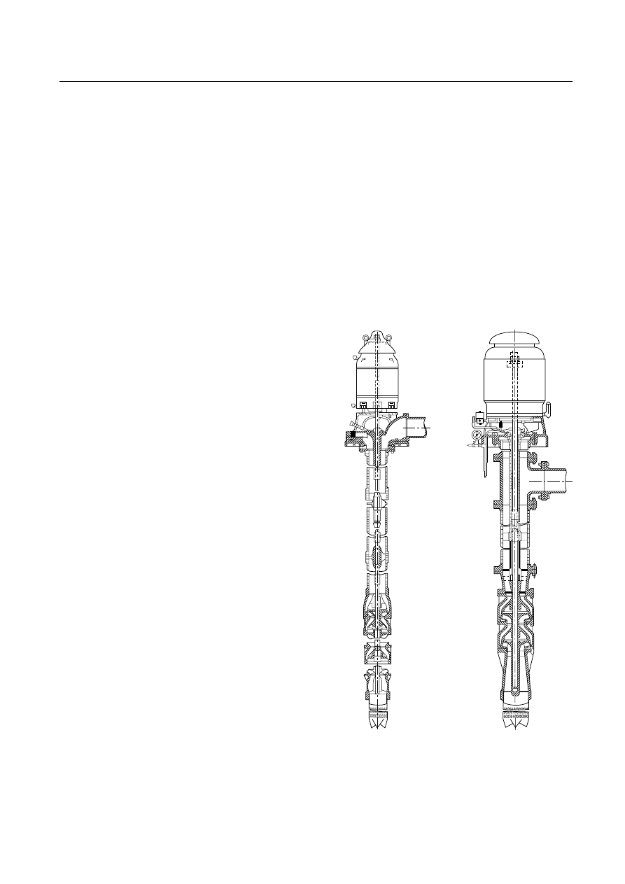
Allowance may be necessary for temperature changes and
for coupling halves that are not of the same outside diameter.
Care should be taken to have the straight edge parallel to the
axes of the shafts.
Angular and parallel misalignment are corrected by means
of shims under the motor mounting feet. After each change, it
is necessary to recheck the alignment of the coupling halves.
Adjustment in one direction can disturb adjustments already
made in another direction. It should not be necessary to adjust
the shims under the pump.
The permissible amount of misalignment will vary with
the type of pump, driver, and coupling manufacturer,
model, and size.
The best method for putting the coupling halves in final
accurate alignment is by the use of a dial indicator.
When the alignment is correct, the foundation bolts
should be tightened evenly but not too firmly. The unit can
then be grouted to the foundation. The base plate should be
completely filled with grout, and it is desirable to grout the
leveling pieces, shims, or wedges in place. Foundation bolts
should not be fully tightened until the grout is hardened, usu-
ally about 48 hours after pouring.
After the grout has set and the foundation bolts have been
properly tightened, the unit should be checked for parallel
and angular alignment, and, if necessary, corrective measures
taken. After the piping of the unit has been connected, the
alignment should be checked again.
The direction of driver rotation should be checked to
make certain that it matches that of the pump. The corre-
sponding direction of rotation of the pump is indicated by a
direction arrow on the pump casing.
The coupling halves can then be reconnected. With the
pump properly primed, the unit then should be operated un-
der normal operating conditions until temperatures have sta-
bilized. It then should be shut down and immediately checked
again for alignment of the coupling. All alignment checks
should be made with the coupling halves disconnected and
again after they are reconnected.
After the unit has been in operation for about 10 hours
or 3 months, the coupling halves should be given a final
check for misalignment caused by pipe or temperature
strains. If the alignment is correct, both pump and driver
should be dowelled to the base plate. Dowel location is very
important and the manufacturer’s instructions should be
followed, especially if the unit is subjected to temperature
changes.
The unit should be checked periodically for alignment. If
the unit does not stay in line after being properly installed, the
following are possible causes:
(1) Settling, seasoning, or springing of the foundation and
pipe strains distorting or shifting the machine
(2) Wearing of the bearings
(3) Springing of the base plate by heat from an adjacent
steam pipe or from a steam turbine
(4) Shifting of the building structure due to variable loading
or other causes
(5) The unit and foundation are new, and the alignment
might need to be slightly readjusted from time to time.
A.7.1
Satisfactory operation of vertical turbine–type pumps is
dependent to a large extent upon careful and correct installa-
tion of the unit; therefore, it is recommended that this work
be done under the direction of a representative of the pump
manufacturer.
A.7.1.1
The vertical shaft turbine–-type pump is particu-
larly suitable for fire pump service where the water source is
located below ground and where it would be difficult to
install any other type of pump below the minimum water
level. It was originally designed for installation in drilled
wells but is permitted to be used to lift water from lakes,
streams, open swamps, and other subsurface sources. Both
oil-lubricated
enclosed-line-shaft
and
water-lubricated
open-line-shaft pumps are used. (See Figure A.7.1.1.) Some
health departments object to the use of oil-lubricated
pumps; such authorities should be consulted before pro-
ceeding with oil-lubricated design.
A.7.2.1.1
Stored water supplies from reservoirs or tanks sup-
plying wet pits are preferable. Lakes, streams, and groundwa-
ter supplies are acceptable where investigation shows that they
can be expected to provide a suitable and reliable supply.
Oil-lubricated,
enclosed lineshaft pump,
underground discharge,
flanged column and bowls
Water-lubricated,
open lineshaft pump,
surface discharge,
threaded column and bowls
FIGURE A.7.1.1 Water-Lubricated and Oil-Lubricated Shaft
Pumps.
20
–60
INSTALLATION OF STATIONARY PUMPS FOR FIRE PROTECTION
2003 Edition
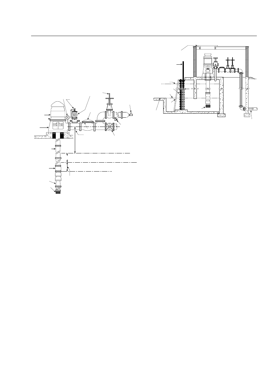
A.7.2.1.2
The authority having jurisdiction can require an
aquifer performance analysis. The history of the water table
should be carefully investigated. The number of wells already
in use in the area and the probable number that can be in use
should be considered in relation to the total amount of water
available for fire protection purposes.
A.7.2.2.1
See Figure A.7.2.2.1.
A.7.2.2.2
The velocities in the approach channel or intake
pipe should not exceed approximately 0.7 m/sec (2 ft/sec),
and the velocity in the wet pit should not exceed approxi-
mately 0.3 m/sec (1 ft/sec). (See Figure A.7.2.2.2.)
The ideal approach is a straight channel coming directly to
the pump. Turns and obstructions are detrimental because
they can cause eddy currents and tend to initiate deep-cored
vortices. The amount of submergence for successful operation
will depend greatly on the approaches of the intake and the
size of the pump.
The Hydraulics Institute Standards for Centrifugal, Rotary and
Reciprocating Pumps recommends sump dimensions for flows
11,355 L/min (3000 gpm) and larger. The design of sumps for
pumps with discharge capacities less than 11,355 L/min
(3000 gpm) should be guided by the same general principles
shown in the Hydraulics Institute Standards for Centrifugal, Rotary
and Reciprocating Pumps.
A.7.2.5
Where wells take their supply from consolidated forma-
tions such as rock, the specifications for the well should be de-
cided upon by the authority having jurisdiction after consulta-
tion with a recognized groundwater consultant in the area.
A.7.2.7
Before the permanent pump is ordered, the water
from the well should be analyzed for corrosiveness, includ-
ing such items as pH, salts such as chlorides, and harmful
gases such as carbon dioxide (CO
2
) or hydrogen sulfide
(H
2
S). If the water is corrosive, the pumps should be con-
structed of a suitable corrosion-resistant material or cov-
ered with special protective coatings in accordance with the
manufacturers’ recommendations.
A.7.3.1
See Figure A.7.3.1.
A.7.3.2.1
In countries that utilize the metric system, there do
not appear to be standardized flow ratings for pump capaci-
ties; therefore, a soft metric conversion is utilized.
A.7.3.5.3
Water level detection using the air line method is
as follows:
(1) A satisfactory method of determining the water level
involves the use of an air line of small pipe or tubing of
known vertical length, a pressure or depth gauge, and
an ordinary bicycle or automobile pump installed as
shown in Figure A.7.3.5.3. The air line pipe should be
of known length and extend beyond the lowest antici-
pated water level in the well, to ensure more reliable
gauge readings, and should be properly installed. An
air pressure gauge is used to indicate the pressure in
the air line. (See Figure A.7.3.5.3.)
(2) The air line pipe is lowered into the well, a tee is placed
in the line above the ground, and a pressure gauge is
screwed into one connection. The other connection is
fitted with an ordinary bicycle valve to which a bicycle
pump is attached. All joints should be made carefully
and should be airtight to obtain correct information.
When air is forced into the line by means of the bicycle
pump, the gauge pressure increases until all of the wa-
ter has been expelled. When this point is reached, the
gauge reading becomes constant. The maximum main-
tained air pressure recorded by the gauge is equivalent
to that necessary to support a column of water of the
same height as that forced out of the air line. The
length of this water column is equal to the amount of
air line submerged.
Hose valves
preferably
located
outside
Drain valve
or ball drip
Discharge
gate valve
Discharge tee
Static water level before pumping
Pumping water level at 150 percent
of rated pump capacity
Drain down
Basket suction
strainer
(alternate
conical strainer)
Suction nozzle
Pump bowl
assembly
Column pipe
Discharge
head
Hollow
shaft
electric
motor
Discharge gauge
Hose connection gate valve
Discharge
check
valve
Air release
valve
Relief valve
Minimum
submergence
3.2 m (10 ft)
Note: The distance between the bottom of the strainer and the bottom
of the wet pit should be one-half of the pump bowl diameter but not less
than 305 mm (12 in.).
FIGURE A.7.2.2.1 Vertical Shaft Turbine–Type Pump Instal-
lation in a Well.
High water
Screens
Lowest standing
water level
Strainer
Yard system
Removable panel
Screen raised
Rack
Bottom
of reservoir
FIGURE A.7.2.2.2 Vertical Shaft Turbine–Type Pump Instal-
lation in a Wet Pit.
20
–61
ANNEX A
2003 Edition
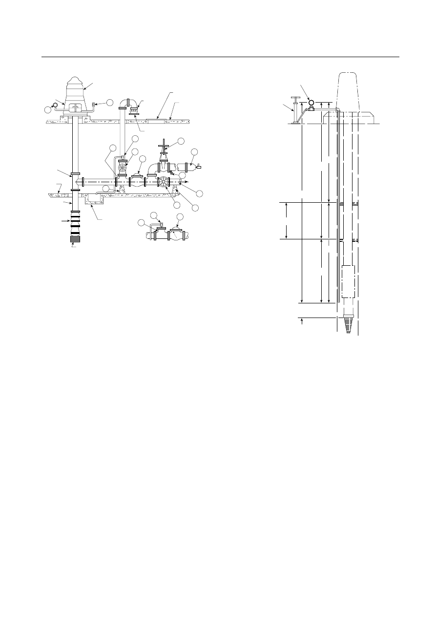
(3) Deducting this pressure converted to meters (feet)
(pressure in bar × 10.3 = pressure in meters, and pres-
sure in psi × 2.31 = pressure in feet) from the known
length of the air line will give the amount of
submergence.
Example: The following calculation will serve to clarify
Figure A.7.3.5.3.
Assume a length (L) of 15.2 m (50 ft).
The pressure gauge reading before starting the fire
pump (p
1
) = 0.68 bar (10 psi). Then A = 0.68 × 10.3 = 7.0 m
(10 × 2.31 = 23.1 ft). Therefore, the water level in the well
before starting the pump would be B = L − A = 15.2 m − 7 m
= 8.2 m (B = L − A = 50 ft − 23.1 ft = 26.9 ft).
The pressure gauge reading when pump is running
(p
2
) = 0.55 bar (8 psi). Then C = 0.55 × 10.3 = 5.6 m (8 × 2.31
= 18.5 ft). Therefore, the water level in the well when the
pump is running would be D = L − C = 15.2 m − 5.6 m = 9.6 m
(D = L − C = 50 ft − 18.5 ft = 31.5 ft).
The drawdown can be determined by any of the following
methods:
(1) D − B = 9.6 m − 8.2 m = 1.4 m (31.5 ft − 26.9 ft = 4.6 ft)
(2) A − C = 7.0 m − 5.6 m = 1.4 m (23.1 ft − 18.5 ft = 4.6 ft)
(3) p
1
− p
2
= 0.68 − 0.55 = 0.13 bar = 0.13 × 10.3 = 1.4 m
(10 − 8 = 2 psi = 2 × 2.31 = 4.6 ft)
A.7.4
Several methods of installing a vertical pump can be
followed, depending upon the location of the well and facili-
ties available. Since most of the unit is underground, extreme
care should be used in assembly and installation, thoroughly
checking the work as it progresses. The following simple
method is the most common:
(1) Construct a tripod or portable derrick and use two sets of
installing clamps over the open well or pump house. After
the derrick is in place, the alignment should be checked
carefully with the well or wet pit to avoid any trouble when
setting the pump.
(2) Attach the set of clamps to the suction pipe on which the
strainer has already been placed and lower the pipe into
the well until the clamps rest on a block beside the well
casing or on the pump foundation.
(3) Attach the clamps to the pump stage assembly, bring the
assembly over the well, and install pump stages to the suc-
tion pipe, until each piece has been installed in accor-
dance with the manufacturer’s instructions.
A.7.6.1.1
The setting of the impellers should be undertaken
only by a representative of the pump manufacturer. Improper
setting will cause excessive friction loss due to the rubbing of
6
9
10
Service
floor
Column
pipe
Pump bowl
assembly
Sump
Strainer
9
3
1
5
4
8
7
10
Pipe to
waste
To system
Installation with
relief valve
2
Discharge
tee
Head
Hollow shaft
electric motor (shown);
right-angle gear for
engine drive (not shown)
1
Access
manhole
Top
floor
Cone or
funnel
1 Automatic air release
2 Discharge gauge
3 Reducing discharge tee
4 Discharge check valve
5 Relief valve (if required)
6 Discharge pipe
7 Drain valve or ball drip
8 Hose valve manifold with hose valves
9 Pipe supports
10 Indicating gate or indicating butterfly
valve
3
1
4
Installation
without relief valve
FIGURE A.7.3.1 Belowground Discharge Arrangement.
C
A
D
B
Pressure gauge
Air pump
Drawdown
L
*
Approximately 50 mm (2 in.) above
strainer flange to keep clear from
water flow in pump
*
Must be known.
FIGURE A.7.3.5.3 Air Line Method of Determining Depth of
Water Level.
20
–62
INSTALLATION OF STATIONARY PUMPS FOR FIRE PROTECTION
2003 Edition
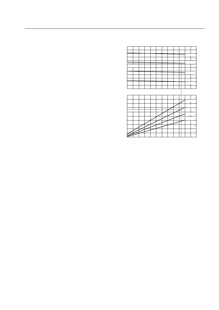
impellers on pump seals, which results in an increase in power
demand. If the impellers are adjusted too high, there will be a
loss in capacity, and full capacity is vital for fire pump service. The
top shaft nut should be locked or pinned after proper setting.
A.7.6.1.4
Pumping units are checked at the factory for
smoothness of performance and should operate satisfactorily
on the job. If excessive vibration is present, the following con-
ditions could be causing the trouble:
(1) Bent pump or column shaft
(2) Impellers not properly set within the pump bowls
(3) Pump not hanging freely in the well
(4) Strain transmitted through the discharge piping
Excessive motor temperature is generally caused either by
a maintained low voltage of the electric service or by improper
setting of impellers within the pump bowls.
A.8.1
All the requirements in Chapter 5 might not apply to
positive displacement pumps.
A.8.1.2
Special attention to the pump inlet piping size and
length should be noted.
A.8.1.2.2
This material describes a sample pump characteris-
tic curve and gives an example of pump selection methods.
Characteristic performance curves should be in accordance
with HI 3.6, Rotary Pump Tests.
Example: An engineer is designing a foam-water fire pro-
tection system. It has been determined, after application of
appropriate safety factors, that the system needs a foam
concentrate pump capable of 45 gpm at the maximum sys-
tem pressure of 230 psi. Using the performance curve (see
Figure A.8.1.2.2) for pump model “XYZ -987,” this pump is
selected for the application. First, find 230 psi on the hori-
zontal axis labeled “Differential pressure,” then proceed
vertically to the flow curve to 45 gpm. It is noted that this
particular pump produces 46 gpm at a standard motor
speed designated “rpm-2.” This pump is an excellent fit for
the application. Next, proceed to the power curve for the
same speed of rpm-2 at 230 psi and find that it requires
13.1 hp to drive the pump. An electric motor will be used
for this application, so a 15 hp motor at rpm-2 is the first
available motor rating above this minimum requirement.
A.8.1.5
Positive displacement pumps are tolerance depen-
dent. Corrosion can affect pump performance and function.
(See HI 3.5, Standard for Rotary Pumps for Nomenclature, Design,
Application and Operation.)
A.8.2.2
Specific flow rates should be determined by the
applicable NFPA standard. Viscose concentrates and addi-
tives have significant pipe friction loss from the supply tank
to the pump suction.
A.8.2.5
Generally, pump capacity is calculated by multiplying
the maximum water flow by the percentage of concentration
desired. To that product is added a 10 percent “over demand”
to ensure that adequate pump capacity is available under all
conditions.
A.8.2.6
Generally, concentrate pump discharge pressure is
required to be added to the maximum water pressure at the
injection point plus 2 bar (25 psi).
A.8.3.1
It is not the intent of this standard to prohibit the use
of stationary pumps for water mist systems.
A.8.4.2
Positive displacement pumps are capable of quickly ex-
ceeding their maximum design discharge pressure if operated
against a closed discharge system. Other forms of protective de-
vices (e.g., automatic shutdowns, rupture discs) are considered a
part of the pumping system and are generally beyond the scope
of the pump manufacturer’s supply. These components should
be safely designed into and supplied by the system designer
and/or by the user. (See Figure A.8.4.2 for proposed schematic layout of
pump requirements.)
A.8.4.3
Only the return to source and external styles should
be used when the outlet line can be closed for more than a few
minutes. Operation of a pump with an integral relief valve and
a closed outlet line will cause overheating of the pump and a
foamy discharge of fluid after the outlet line is reopened.
A.8.4.4
Backpressure on the discharge side of the pressure
relief valve should be considered. (See Figure A.8.4.4 for proposed
schematic layout of pump requirement.)
A.8.4.5
Strainer recommended mesh size is based on the
internal pump tolerances. (See Figure A.8.4.5 for standard
mesh sizes.)
A.8.5.1
Positive displacement pumps are typically driven by
electric motors, internal combustion engines, or water motors.
A.8.6
These controllers can incorporate means to permit
automatic unloading or pressure relief when starting the
pump driver.
Motor horsep
o
w
er (hp) required
14
kW required
12
10
8
6
4
2
0
0
25
50
75 100 125 150 175 200 225 250 275 300
rpm - 1
rpm - 2
rpm - 3
rpm - 4
Differential pressure (psi)
Capacity (gpm)
L/min
125
100
75
50
(46 gpm)
(13.1 hp)
20
18
16
14
12
10
8
6
4
2
0
70
65
60
55
50
45
40
35
30
25
10
20
15
150
175
200
225
250
Example Pump Company
Pump Model: XYZ-987
UL listed for capacity range of 20 gpm to 60 gpm*
rpm - 4
rpm - 3
rpm - 2
rpm - 1
*Conforms to requirements of Chapter 8 on positive displacement foam
concentrate and additive pumps.
FIGURE A.8.1.2.2 Example of Positive Displacement Pump
Selection.
20
–63
ANNEX A
2003 Edition
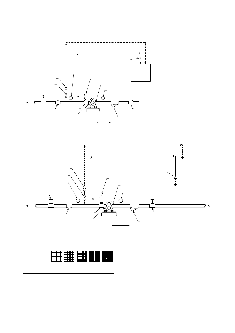
A.9.2.3
An on-site electrical power production facility located
on the premises served by the fire pump is considered an ac-
ceptable facility if it is in a separate power house or cut off
from the main buildings. It can be used as one of the two
sources of current supply. Where two sources are used with
power transfer switches, see NFPA 70, National Electrical Code,
Article 695.
A.9.2.4
A reliable power source possesses the following
characteristics:
(1) Infrequent power disruptions from environmental or
manmade conditions
To foam
system
Foam tank
Acceptable method to return relief valve flow
Foam flow test loop
Sight glass
OS&Y suction isolation
gate valve
Suction strainer
10 pipe diameters minimum
Pump suction port
Pressure relief valve
Pipe tee
Pump discharge port
Check valve
OS&Y discharge
isolation gate valve
Test isolation valve
Orifice plate test device
89 mm (3 ¹⁄₂ in. ) discharge gauge
89 mm (3 ¹⁄₂ in.)
compound suction
gauge
FIGURE A.8.4.2 Typical Foam Pump Piping and Fittings.
To water
mist system
Acceptable method to return relief valve flow
Flow test loop
Sight glass
*
*
OS&Y suction isolation
gate valve
Suction strainer
10 pipe diameters minimum
89 mm (3 ¹⁄₂ in.) compound
suction gauge
* Acceptable to
plumb to drain,
pump suction,
or supply
Pump suction port
Pressure relief valve
Pipe tee
Pump discharge port
Check valve
OS&Y discharge
isolation gate valve
Test isolation valve
Orifice plate test device
89 mm (3 ¹⁄₂ in.)
discharge gauge
From
supply
FIGURE A.8.4.4 Typical Water Mist System Pump Piping and Fittings.
Mesh
Opening (in.)
Opening (µ)
20
0.034
860
40
0.015
380
60
0.0092
230
80
0.007
190
100
0.0055
140
FIGURE A.8.4.5 Standard Mesh Sizes.
20
–64
INSTALLATION OF STATIONARY PUMPS FOR FIRE PROTECTION
2003 Edition
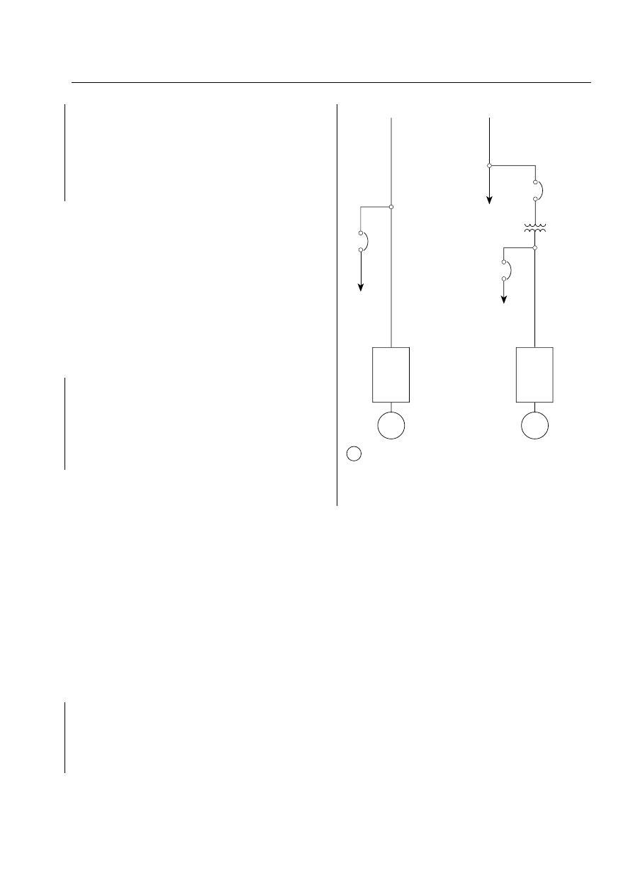
(2) A separate service connection or connection to the supply
side of the service disconnect
(3) Service and feeder conductors either buried under
50 mm (2 in.) of concrete or encased in 50 mm (2 in.) of
concrete or brick within a building
Typical methods of routing power from the source to the mo-
tor are shown in Figure A.9.3.2. Other configurations are also
acceptable. The determination of the reliability of a service is left
up to the discretion of the authority having jurisdiction.
A.9.3
Where risks involved are large and interruption of fire
pump service would seriously affect protection, at least two
separate circuits from the power plant(s) to the pump room
should be provided. The circuits should be run by separate
routes or in such a manner that failure of more than one at the
same time would be only a remote possibility.
A completely underground circuit from the generating sta-
tion to the pump room is strongly recommended and should
be obtained where practicable. Where such construction is
not available, an overhead circuit is allowed, but that part of
the circuit adjacent to the plant served by the fire pump or to
exposing plants should be run with special reference to dam-
age in case of fire. Where the pump room is part of, or in close
proximity to, the plant that the pump is designed to protect,
the wires should be underground for some distance from the
pump room.
A.9.3.1
Under premise fire conditions, service and feeder
connections are susceptible to failure from collapsing struc-
tural and other members within the premise as well as failure
from fire. Under fire conditions generated by overcurrent
within these service and feeder conductors, the characteristics
of 9.3.1 minimize the possibility of fire spread.
Typical methods of routing power from the source to the
motor are shown in Figure A.9.3.2. Other configurations are
also acceptable.
A.9.3.2
See Figure A.9.3.2.
A.9.3.2.2.2
Where the alternate power is from an on-site gen-
erator, the alternate service equipment need not be located in
the fire pump room.
The committee considered the potential arrangement of
providing fire pump power from the secondary side of the
transformer, which supplies other electrical loads of the facil-
ity. The committee recognizes that it is possible to supply the
fire pump power ahead of other plant loads and to protect the
fire pump power circuit by proper electrical coordination.
However, the committee is concerned that, while responding
to an emergency, fire fighters might seek to disconnect electri-
cal power to the facility by opening the transformer primary
disconnect, which in this case would isolate power to the fire
pump as well. In addition, the committee is concerned that
the designed electrical coordination can be compromised by
ongoing additional electrical loads to the facility power distri-
bution system. Therefore, if electrical service is supplied to the
facility at voltage higher than utilization voltage, the commit-
tee feels that a separate transformer to provide power to the
fire pump is appropriate.
A.9.4
Normally, conductor sizing is based on appropriate sec-
tions of NFPA 70, National Electrical Code, Article 430, except larger
sizes could be required to meet the requirements of NFPA 70,
Section 695.7 (NFPA 20, Section 9.4). Transformer sizing is to be
in accordance with NFPA 70, Section 695.5(a), except larger
minimum sizes could be required to meet the requirements of
NFPA 70, Section 695.7 (NFPA 20, Section 9.4).
A.9.5.1.3
The locked rotor currents for 460 V motors are ap-
proximately six times the full-load current.
A.9.6.2
Where a generator is installed to supply power to
loads in addition to one or more fire pump drivers, the fuel
supply should be sized to provide adequate fuel for all con-
nected loads for the desired duration. The connected loads
can include such loads as emergency lighting, exit signage,
and elevators.
A.10.1.2.2
The phrase suitable for use means that the controller
and transfer switch have been prototype tested and have demon-
strated by these tests their short-circuit withstandability and inter-
rupting capacity at the stated magnitude of short-circuit current
and voltage available at their line terminals. (See ANSI/ U L 509,
Standard for Safety Industrial Control Equipment, and ANSI/ U L 1008,
Standard for Safety Automatic Transfer Switches.)
A short-circuit study should be made to establish the
available short-circuit current at the controller in accor-
dance with IEEE 141, Electric Power Distribution for Industrial
Plants; IEEE 241, Electric Systems for Commercial Buildings; or
other acceptable methods.
After the controller and transfer switch have been sub-
jected to a high fault current, they may not be suitable for
further use without inspection or repair. (See NEMA ICS 2.2,
Maintenance of Motor Controllers After a Fault Condition.)
Arrang ement A
Arrang ement B
Service at fire
pump motor
utilization
voltage
Service conductors
(see NFPA 70, Article 230)
Service conductors
(see NFPA 70, Article 230)
Service at other than
fire pump motor
utilization voltage
To fire
pump
auxiliary
loads
(optional)
Fire
pump
controller
To other
service switches
and plant loads
To fire pump auxiliary
loads (optional)
Overcurrent protection
per NFPA 70,
Sections 240.3(a)
and 695.5
Connection
per NFPA 70,
Section
450.3(a)(3)
Fire
pump
controller
M
M
*Circuit breakers or fusible switches can be used.
*Service
equipment
(
see 9.3.2.2.5
)
M
Motor
*
*
FIGURE A.9.3.2 Typical Power Supply Arrangements from
Source to Motor.
20
–65
ANNEX A
2003 Edition
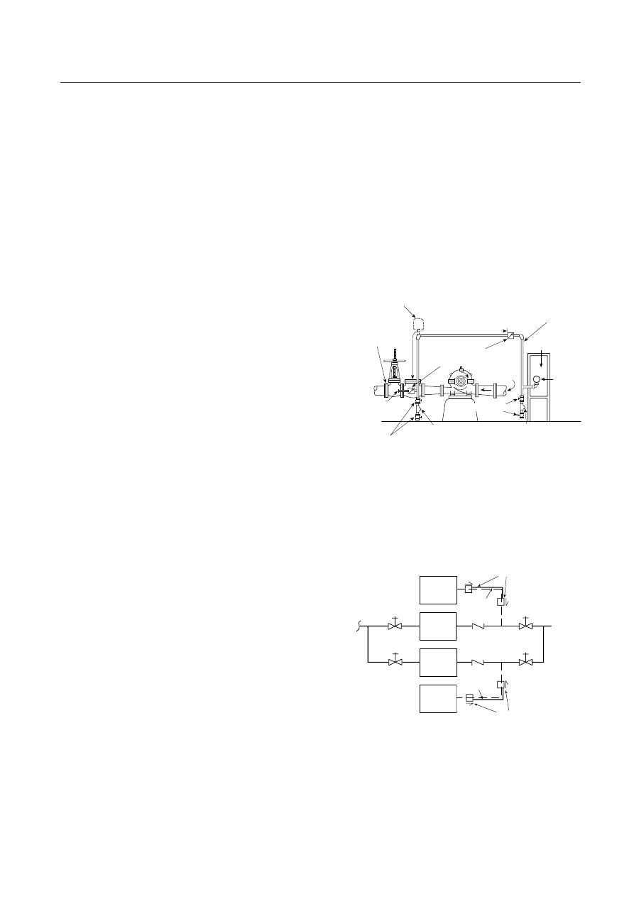
A.10.2.1
If the controller must be located outside the pump
room, a glazed opening should be provided in the pump
room wall for observation of the motor and pump during start-
ing. The pressure control pipe line should be protected
against freezing and mechanical injury.
A.10.3.3.1
For more information, see NEMA 250, Enclosures
for Electrical Equipment.
A.10.3.6
For more information, see NFPA 70, National Electri-
cal Code.
A.10.3.7.3
Pump operators should be familiar with instruc-
tions provided for controllers and should observe in detail all
their recommendations.
A.10.4.1
Operation of the surge arrester should not cause
either the isolating switch or the circuit breaker to open. Ar-
resters in ANSI/IEEE C62.11, IEEE Standard for Metal-Oxide
Surge Arresters for AC Power Circuits, are normally zinc-oxide
without gaps.
A.10.4.2.1.2
For more information, see NFPA 70, National
Electrical Code.
A.10.4.2.3
For more information, see NFPA 70, National Elec-
trical Code.
A.10.4.3.1
For more information, see NFPA 70, National Elec-
trical Code, Article 100.
A.10.4.3.3
Attention should be given to the type of service
grounding to establish circuit breaker interrupting rating
based on grounding type employed.
A.10.4.3.3.1(4)
The interrupting rating can be less than the
suitability rating where other devices within the controller as-
sist in the current-interrupting process.
A.10.4.3.3.2
Current limiters are melting link-type devices
that, where used as an integral part of a circuit breaker, limit
the current during a short circuit to within the interrupting
capacity of the circuit breaker.
A.10.4.4.1(3)
It is recommended that the locked rotor overcur-
rent device not be reset more than two consecutive times if
tripped due to a locked rotor condition without first inspecting
the motor for excessive heating and to alleviate or eliminate the
cause preventing the motor from attaining proper speed.
A.10.4.5.6.2
The alarm should incorporate local visible indi-
cation and contacts for remote indication. The alarm can be
incorporated as part of the power available indication and loss
of phase alarm [see 10.4.6.1 and 10.4.7.2(B)].
A.10.4.6
The pilot lamp for alarm and signal service should
have operating voltage less than the rated voltage of the lamp
to ensure long operating life. When necessary, a suitable resis-
tor or potential transformer should be used to reduce the volt-
age for operating the lamp.
A.10.4.7
Where unusual conditions exist whereby pump op-
eration is not certain, a “failed-to-operate” alarm is recom-
mended. In order to supervise the power source for the alarm
circuit, the controller can be arranged to start upon failure of
the supervised alarm circuit power.
A.10.5.1
The following definitions are derived from NFPA 70,
National Electrical Code:
(1) Automatic. Self-acting, operating by its own mechanism when
actuated by some impersonal influence, as, for example, a
change in current strength, pressure, temperature, or me-
chanical configuration.
(2) Nonautomatic. Action requiring intervention for its con-
trol. As applied to an electric controller, nonautomatic
control does not necessarily imply a manual controller,
but only that personal intervention is necessary.
A.10.5.2.1
Installation of the pressure-sensing line between
the discharge check valve and the control valve is necessary to
facilitate isolation of the jockey pump controller (and sensing
line) for maintenance without having to drain the entire sys-
tem. [See Figure A.10.5.2.1(a) and Figure A.10.5.2.1(b).]
Not less than 5 ft 0 in.
Indicating
control valve
Connect to a
tapped boss
or other
suitable
outlet between
the indicating
control valve
and check valve
¹⁄₂
in. globe valves
If water pulsation causes erratic operation of the
pressure switch or the recorder, a supplemental air chamber
or pulsation damper might be needed
¹⁄₄
in. plug
¹⁄₂
in. globe valves
Suction
Bronze check valves with
³⁄₃₂
in. orifice in clapper
Not less than ¹⁄₂ in. brass pipe
with brass fittings or equivalent
Control panel
Pressure
switch
A
B
Test connection at A or B
¹⁄₄
in. plug
Notes:
1. Solenoid drain valve used for engine-driven fire pumps can be at A, B,
or inside controller enclosure.
2. If water is clean, ground-face unions with noncorrosive diaphragms
drilled for ³⁄₃₂ in. orifices can be used in place of the check valves.
3. For SI units, 1 in. = 25.4 mm; 1 ft = 0.3048 m.
FIGURE A.10.5.2.1(a)
Piping Connection for Each Auto-
matic Pressure Switch (for Fire Pump and Jockey Pumps).
Note: Check valves or ground-face unions complying with 10.5.2.1.
Jockey
pump
controller
Fire
protection
system
See Note
See Note
Water
supply
Fire
pump
controller
Jockey
pump
Fire
pump
Minimum
1.5 m (5 ft)
Minimum
1.5 m (5 ft)
FIGURE A.10.5.2.1(b)
Piping Connection for Pressure-
Sensing Line.
20
–66
INSTALLATION OF STATIONARY PUMPS FOR FIRE PROTECTION
2003 Edition
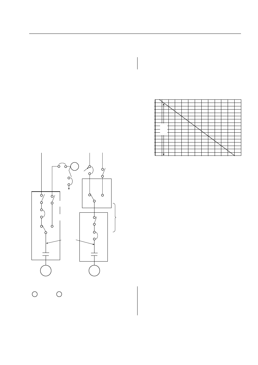
A.10.5.2.1.6(E)
The pressure recorder should be able to
record a pressure at least 150 percent of the pump discharge
pressure under no-flow conditions. In a high-rise building,
this requirement can exceed 27.6 bar (400 psi). This pressure
recorder should be readable without opening the fire pump
controller enclosure. This requirement does not mandate a
separate recording device for each controller. A single multi-
channel recording device can serve multiple sensors.
A.10.5.3.2
The emergency-run mechanical control provides
means for externally, manually closing the motor contactor
across-the-line to start and run the fire pump motor. It is in-
tended for emergency use when normal electric/magnetic op-
eration of the contactor is not possible.
When so used on controllers designed for reduced-voltage
starting, the 15 percent voltage drop limitation in Section 9.4
is not applicable.
A.10.7
The authority having jurisdiction can permit the use
of a limited-service controller for special situations where such
use is acceptable to said authority.
A.10.8
Typical fire pump controller and transfer switch ar-
rangements are shown in Figure A.10.8. Other configurations
can also be acceptable.
A.10.8.2
The compartmentalization or separation is to pre-
vent propagation of a fault in one compartment to the source
in the other compartment.
A.11.1.2
The compression ignition diesel engine has proved
to be the most dependable of the internal combustion engines
for driving fire pumps.
A.11.2.2.2
For more information, see SAE J-1349, Engine
Power Test Code — Spark Ignition and Compression Engine.
A.11.2.2.4
See Figure A.11.2.2.4.
A.11.2.2.5
Pump room temperature rise should be consid-
ered when determining the maximum ambient temperature
specified. (See Figure A.11.2.2.5.)
A.11.2.4.8
A harness on the enclosure will ensure ready wiring
in the field between the two sets of terminals.
A.11.2.4.9
Terminations should be made using insulated
ring-type compression connectors for post-type terminal
blocks. Saddle-type terminal blocks should have the wire
stripped with about 1.6 mm (
1
⁄
16
in.) of bare wire showing after
insertion in the saddle to ensure that no insulation is below
the saddle. Wires should be tugged to ensure adequate tight-
ness of the termination.
A.11.2.4.10
Manual mechanical operation of the main bat-
tery contactor will bypass all of the control circuit wiring
within the controller.
A.11.2.4.13
Traditionally, engines have been built with me-
chanical devices to control the injection of fuel into the com-
bustion chamber. To comply with requirements for reduced
exhaust emissions, many engine manufacturers have incorpo-
rated electronics to control the fuel injection process, thus
eliminating levers and linkages. Many of the mechanically
controlled engines are no longer manufactured.
To other
generator
loads
Transfer
switch
N
E
*
Circuit breakers or fusible switches can be used.
See
10.8.2.2
See
9.3.2
See 9.6.5
Normal
source
Alternate
source
M
G
Motor
Generator
Phase loss/
phase
reversal
monitoring
point
M
Normal
source
G
N
E
See
10.8.2.1
See
10.8.2.1.2
M
E Emergency
N Normal
Alternate
source
ARRANGEMENT II
ARRANGEMENT I
*
*
*
FIGURE A.10.8 Typical Fire Pump Controller and Transfer
Switch Arrangements.
1.02
1.00
0.98
0.96
0.94
0.92
0.90
0.88
0.86
0.84
0.82
0.80
0.78
0.76
0.74
0.72
0.70
0.68
(0)
(2,000)
(4,000)
(6,000)
(8,000) (10,000)
Elevation above sea level, m (ft)
De
rate
factor (
C
A
)
Note: The correction equation is as follows:
Corrected engine horsepower = (
C
A
+
C
T
– 1) × listed engine horsepower
where:
C
A
= derate factor for elevation
C
T
= derate factor for temperature
(300 ft)
91.4 m
610
0
1,219
1,829
2,438
3,048
FIGURE A.11.2.2.4 Elevation Derate Curve.
20
–67
ANNEX A
2003 Edition
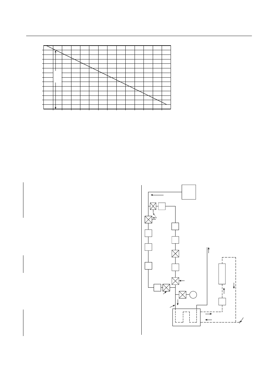
A.11.2.4.13.5
ECMs can be designed by engine manufactur-
ers to monitor various aspects of engine performance. A
stressed engine condition (such as high cooling water tem-
perature) is usually monitored by the ECM and is built into
the ECM control logic to reduce the horsepower output of
the engine, thus providing a safeguard for the engine. Such
engine safeguards are not permitted for ECMs in fire pump
engine applications.
A.11.2.5.2.3
A single charger that automatically alternates from
one battery to another can be used on two battery installations.
A.11.2.5.2.5
Location at the side of and level with the engine is
recommended to minimize lead length from battery to starter.
A.11.2.5.4.4
Automatic maintenance of air pressure is pref-
erable.
A.11.2.6.3
See Figure A.11.2.6.3. Water supplied for cooling
the heat exchanger is sometimes circulated directly through
water-jacketed exhaust manifolds and/or engine aftercoolers
in addition to the heat exchangers.
A.11.2.6.4
Where the water supply can be expected to con-
tain foreign materials, such as wood chips, leaves, lint, and so
forth, the strainers required in 11.2.6.3 should be of the du-
plex filter type. Each filter (clean) element should be of suffi-
cient filtering capacity to permit full water flow for a 3 hour
period. In addition, a duplex filter of the same size should be
installed in the bypass line. (See Figure A.11.2.6.3.)
A.11.3
The engine-driven pump can be located with an
electric-driven fire pump(s) in a pump house or pump room
that should be entirely cut off from the main structure by non-
combustible construction. The fire pump house or pump
room can contain facility pumps and/or equipment as deter-
mined by the authority having jurisdiction.
Note: The correction equation is as follows:
Corrected engine horsepower = (
C
A
+
C
T
– 1) × listed engine horsepower
where:
C
A
= derate factor for elevation
C
T
= derate factor for temperature
1.00
0.99
0.98
0.97
0.96
0.95
0.94
0.93
0.92
0.91
0.90
0.89
0.88
(75)
(95)
(115)
(135)
(155)
(175)
(195)
De
rate
factor (
C
T
)
Ambient air temperature at engine inlet, °C (°F)
(65)
(85)
(105)
(125)
(145)
(165)
(185)
(205)
18.3 23.9 29.4
35
40.6 46.1 51.7 57.2 62.8 68.3 73.9 79.4
85.0 90.6 96.1
25
°C
(77
°F)
FIGURE A.11.2.2.5 Temperature Derate Curve.
Heat
exchanger
Raw
water
line
Indicating
manual
valve
Union
Pressure
gauge
Indicating
manual
valve
Engine
block
Circulating
system
Filling
connection
Drain
Coolant
pump
Union
Automatic
valve
Pressure
regulator
Strainer
Fire
pump
Fire pump
discharge
Union
Indicating
manual
valves
Union
Strainer
Pressure
regulator
FIGURE A.11.2.6.3 Cooling Water Line with Bypass.
20
–68
INSTALLATION OF STATIONARY PUMPS FOR FIRE PROTECTION
2003 Edition
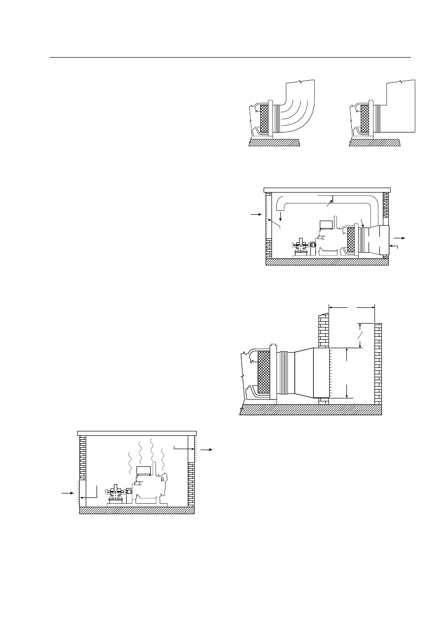
A.11.3.2
For optimum room ventilation, the air supply venti-
lator and air discharge should be located on opposite walls.
When calculating the maximum temperature of the pump
room, the radiated heat from the engine, the radiated heat
from the exhaust piping, and all other heat-contributing
sources should be considered.
If the pump room is to be ventilated by a power ventilator,
reliability of the power source during a fire should be consid-
ered. If the power source is unreliable, the temperature rise
calculation should assume the ventilator is not operable.
Air consumed by the engine for combustion should be con-
sidered as part of the air changes in the room.
Pump rooms with heat exchanger–cooled engines will
typically require more air changes than engine air con-
sumption will provide. To control the temperature rise of
the room, additional air flow through the room is normally
required. [See Figure A.11.3.2(a).]
Pump rooms with radiator-cooled engines could have suffi-
cient air changes due to the radiator discharge and engine
consumption. [See Figure A.11.3.2(b).]
A.11.3.2.3
When motor-operated dampers are used in the air
supply path, they should be spring operated to the open posi-
tion and motored closed. Motor-operated dampers should be
signaled to open when or before the engine begins cranking
to start.
The maximum air flow restriction limit for the air supply
ventilator is necessary to be compatible with listed engines to
ensure adequate air flow for cooling and combustion. This
restriction will typically include louvers, bird screen, dampers,
duct, or anything in the air supply path between the pump
room and the outdoors.
Motor-operated dampers are recommended for the heat
exchanger–cooled engines to enhance convection circulation.
Gravity-operated dampers are recommended for use with
radiator-cooled engines to simplify their coordination with
the air flow of the fan.
A.11.3.2.4
When motor-operated dampers are used in the air
discharge path, they should be spring operated to the open
position, motored closed, and signaled to open when or be-
fore the engine begins cranking to start.
Prevailing winds can work against the air discharge ventilator.
Therefore, the winds should be considered when determining
the location for the air discharge ventilator. (See Figure A.11.3.2.4
for the recommended wind wall design.)
For heat exchanger–cooled engines, an air discharge ventila-
tor with motor-driven dampers designed for convection circula-
tion is preferred in lieu of a power ventilator. This arrangement
will require the size of the ventilator to be larger, but it is not
dependent on a power source that might not be available during
the pump operation.
For radiator-cooled engines, gravity-operated dampers are
recommended. Louvers and motor-operated dampers are not
recommended due to the restriction to air flow they create
and the air pressure they must operate against.
The maximum air flow restriction limit for the air discharge
ventilator is necessary to be compatible with listed engines to en-
sure adequate air flow cooling.
Air supply
ventilator
Dampers
Dampers
Air
discharge
ventilator
FIGURE A.11.3.2(a) Typical Ventilation System for a Heat
Exchanger–Cooled Diesel-Driven Pump.
Right
Wrong
If a bend in the ducting cannot be
avoided, it should be radiused and
should include turning vanes to
prevent turbulence and
flow restriction.
This configuration should not be
used; turbulence will not allow
adequate air flow.
Air supply
ventilator
Dampers
Dampers
Flexible
section
Thermostatically
controlled damper
Cold weather
recirculation duct
Discharge
duct
Air
discharge
ventilator
FIGURE A.11.3.2(b)
Typical Ventilation System for a
Radiator-Cooled Diesel-Driven Pump.
3
X
X
height
or width,
whichever
is greater
X
2
Wall
width = 2
X
Locate on
center with
outlet
FIGURE A.11.3.2.4 Typical Wind Wall.
20
–69
ANNEX A
2003 Edition
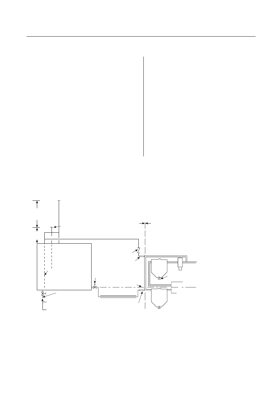
A.11.4.3
The quantity 5.07 L per kW (1 gal per hp) is equiva-
lent to 0.634 L per kW (1 pint per hp) per hour for 8 hours.
Where prompt replenishment of fuel supply is unlikely, a re-
serve supply should be provided along with facilities for trans-
fer to the main tanks.
A.11.4.5
Diesel fuel storage tanks preferably should be lo-
cated inside the pump room or pump house, if permitted by
local regulations. Fill and vent lines in such case should be
extended to outdoors. The fill pipe can be used for a gauging
well where practical.
A.11.4.6
NFPA 31, Standard for the Installation of Oil-Burning
Equipment, can be used as a guide for diesel fuel piping.
Figure A.11.4.6 shows a suggested diesel engine fuel system.
A.11.4.7
The pour point and cloud point should be at least
5.6°C (10°F) below the lowest expected fuel temperature. (See
5.12.2 and 11.4.5.)
A.11.5.3
A conservative guideline is that, if the exhaust system
exceeds 4.5 m (15 ft) in length, the pipe size should be increased
one pipe size larger than the engine exhaust outlet size for each
1.5 m (5 ft) in added length.
A.11.6
Internal combustion engines necessarily embody mov-
ing parts of such design and in such number that the engines
cannot give reliable service unless given diligent care. The
manufacturer’s instruction book covering care and operation
should be readily available, and pump operators should be
familiar with its contents. All of its provisions should be ob-
served in detail.
A.11.6.2
See NFPA 25, Standard for the Inspection, Testing, and
Maintenance of Water-Based Fire Protection Systems, for proper
maintenance of engine(s), batteries, fuel supply, and environ-
mental conditions.
A.11.6.4
Active systems that are permanently added to fuel
tanks for removing water and particulates from the fuel can be
acceptable, provided the following apply:
(1) All connections are made directly to the tank and are not
interconnected with the engine or its fuel supply and re-
turn piping in any way.
(2) There are no valves or other devices added to the engine
or its fuel supply and return piping in any way.
A.11.6.5
Proper engine temperature when the engine is not
running can be maintained through the circulation of hot
water through the jacket or through heating of engine water
by electric elements. As a general rule, water heaters and oil
heaters are required for diesel engines below 21°C (70°F).
The benefits to be gained are as follows:
(1) Quick starting (fire pump engines may have to carry full
load as soon as started)
(2) Reduced engine wear
(3) Reduced drain on batteries
(4) Reduced oil dilution
(5) Reduced carbon deposits, so that the engine is far more
likely to start every time
A.12.2.1
If the controller must be located outside the pump
room, a glazed opening should be provided in the pump room
wall for observation of the motor and pump during starting. The
pressure control pipeline should be protected against freezing
and mechanical injury.
A.12.3.1.1
In areas affected by excessive moisture, heat can
be useful in reducing the dampness.
Mounted on
engine by
manufacturer
Installed
locally
Fuel return
3
(Fuel return pump
can
be necessary for
some engines.)
Check
valve
Flexible
Fill cap, outside [1.6 mm (¹⁄₁₆ in.)
mesh removable wire screen]
5% volume
for expansion
Storage tank
(preferably inside
pump room)
Depth of this fuel return
line is optional, according
to engine manufacturer's
specifications
5% volume for sump
Pitch 6.4 mm (¹⁄₄ in.) per ft
25.4 mm (1 in.) d
rain valve when
not subject to freezing
25.4 mm (1 in.) d
rain plug when
subject to freezing
Manual cock valve,
2
locked open or
central station supervised
Fuel pump centerline
Fuel line protection
3
(where needed)
Flexible
Second-
ary
filter
1
Primary
f
ilter
Engine
Fuel supply
pump
Injector
Condensate
drain
Screened weather vent
Condensate drain
1
Secondary filter behind or before engine fuel pump, according to engine manufacturer's specifications.
2
Excess fuel can be returned to fuel supply pump suction, if recommended by engine manufacturer.
3
Size fuel piping according to engine manufacturer's specifications.
3.05 m
(10 ft)
minimum
305 mm
(12 in.)
FIGURE A.11.4.6 Fuel System for Diesel Engine–Driven Fire Pump.
20
–70
INSTALLATION OF STATIONARY PUMPS FOR FIRE PROTECTION
2003 Edition
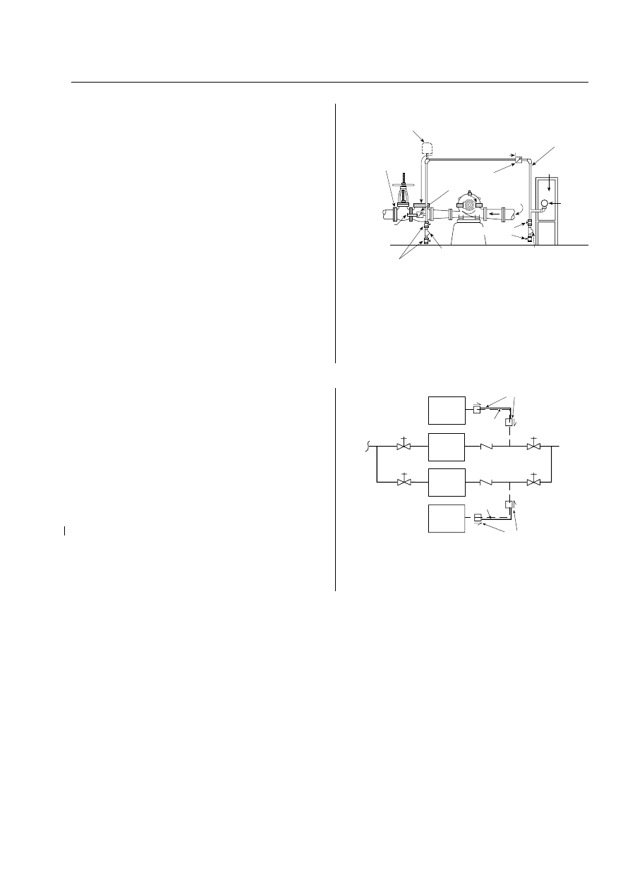
A.12.3.3.1
For more information, see NEMA 250, Enclosures
for Electrical Equipment.
A.12.3.8
Pump operators should be familiar with instructions
provided for controllers and should observe in detail all their
recommendations.
A.12.4.1.2
It is recommended that the pilot lamp for alarm
and signal service have operating voltage less than the rated
voltage of the lamp to ensure long operating life. When neces-
sary, a suitable resistor should be used to reduce the voltage
for operating the lamp.
A.12.4.2.2(3)
The following trouble signals should be moni-
tored remotely from the controller:
(1) A common signal can be used for the following trouble
indications: the items in 12.4.1.3(1) through 12.4.1.3(5)
and loss of output of battery charger on the load side of
the dc overcurrent protective device.
(2) If there is no other way to supervise loss of power, the
controller can be equipped with a power failure circuit,
which should be time delayed to start the engine upon
loss of current output of the battery charger.
A.12.4.4
The pressure recorder should be able to record a pres-
sure at least 150 percent of the pump discharge pressure under
no-flow conditions. In a high-rise building, this requirement can
exceed 27.6 bar (400 psi). This requirement does not mandate a
separate recording device for each controller. A single multichan-
nel recording device can serve multiple sensors.
A.12.5
The following definitions are derived from NFPA 70,
National Electrical Code:
(1) Automatic. Self-acting, operating by its own mechanism
when actuated by some impersonal influence (e.g., a change
in current strength, pressure, temperature, or mechanical
configuration).
(2) Nonautomatic. The implied action requires personal inter-
vention for its control. As applied to an electric controller,
nonautomatic control does not necessarily imply a manual
controller, but only that personal intervention is necessary.
A.12.5.2.1.1
See FigureA.12.5.2.1.1(a) and FigureA.12.5.2.1.1(b).
A.12.5.5.2
Manual shutdown of fire pumps is preferred. Au-
tomatic fire pump shutdown can occur during an actual fire
condition when relatively low-flow conditions signal the con-
troller that pressure requirements have been satisfied.
A.12.6.9
The pressure recorder should be able to record a
pressure at least 150 percent of the pump discharge pres-
sure under no-flow conditions. In a high-rise building, this
requirement can exceed 27.6 bar (400 psi). This require-
ment does not mandate a separate recording device for
each controller. A single multichannel recording device can
serve multiple sensors.
A.13.1.3
Single-stage turbines of maximum reliability and
simplicity are recommended where the available steam supply
will permit.
A.13.2.1.1
The casing can be of cast iron.
Some applications can require a turbine-driven fire pump
to start automatically but not require the turbine to be on
pressure control after starting. In such cases, a satisfactory
quick-opening manual reset valve installed in a bypass of the
steam feeder line around a manual control valve can be used.
Where the application requires the pump unit to start au-
tomatically and after starting continue to operate by means of
a pressure signal, the use of a satisfactory pilot-type pressure
control valve is recommended. This valve should be located in
the bypass around the manual control valve in the steam
feeder line. The turbine governor control valve, when set at
approximately 5 percent above the normal full-load speed of
the pump under automatic control, would act as a pre-
emergency control.
In the arrangements set forth in the two preceding para-
graphs, the automatic valve should be located in the bypass
around the manual control valve, which would normally be
kept in the closed position. In the event of failure of the auto-
matic valve, this manual valve could be opened, allowing the
Not less than 5 ft 0 in.
Indicating
control valve
Connect to a
tapped boss
or other
suitable
outlet between
the indicating
control valve
and check valve
¹⁄₂
in. globe valves
If water pulsation causes erratic operation of the
pressure switch or the recorder, a supplemental air chamber
or pulsation damper might be needed
¹⁄₄
in. plug
¹⁄₂
in. globe valves
Suction
Bronze check valves with
³⁄₃₂
in. orifice in clapper
Not less than ¹⁄₂ in. brass pipe
with brass fittings or equivalent
Control panel
Pressure
switch
A
B
Test connection at A or B
¹⁄₄
in. plug
Notes:
1. Solenoid drain valve used for engine-driven fire pumps can be at A, B,
or inside controller enclosure.
2. If water is clean, ground-face unions with noncorrosive diaphragms
drilled for ³⁄₃₂ in. orifices can be used in place of the check valves.
3. For SI units, 1 in. = 25.4 mm; 1 ft = 0.3048 m.
FIGURE A.12.5.2.1.1(a) Piping Connection for Each Auto-
matic Pressure Switch (for Fire Pump and Jockey Pumps).
Note: Check valves or ground-face unions complying with 10.5.2.1.
Jockey
pump
controller
Fire
protection
system
See Note
See Note
Water
supply
Fire
pump
controller
Jockey
pump
Fire
pump
Minimum
1.5 m (5 ft)
Minimum
1.5 m (5 ft)
FIGURE A.12.5.2.1.1(b)
Piping Connection for Pressure-
Sensing Line.
20
–71
ANNEX A
2003 Edition

turbine to come to speed and be controlled by the turbine
governor control valve(s).
The use of a direct acting pressure regulator operating on
the control valve(s) of a steam turbine is not recommended.
A.13.3
The following information should be taken into con-
sideration when planning a steam supply, exhaust, and boiler
feed for a steam turbine–driven fire pump.
The steam supply for the fire pump should preferably be
an independent line from the boilers. It should be run so as
not to be liable to damage in case of fire in any part of the
property. The other steam lines from the boilers should be
controlled by valves located in the boiler room. In an emer-
gency, steam can be promptly shut off from these lines, leaving
the steam supply entirely available for the fire pump. Strainers
in steam lines to turbines are recommended.
The steam throttle at the pump should close against the
steam pressure. It should preferably be of the globe pattern
with a solid disc. If, however, the valve used has a removable
composition ring, the disc should be of bronze and the ring
made of sufficiently hard and durable material, and so held in
place in the disc as to satisfactorily meet severe service condi-
tions. Gate valves are undesirable for this service because they
cannot readily be made leaktight, as is possible with the globe
type of valve. The steam piping should be so arranged and
trapped that the pipes can be kept free of condensed steam.
In general, a pressure-reducing valve should not be placed
in the steam pipe supplying the fire pump. There is no diffi-
culty in designing turbines for modern high-pressure steam,
and this gives the simplest and most dependable unit. A
pressure-reducing valve introduces a possible obstruction in
the steam line in case it becomes deranged. In most cases, the
turbines can be protected by making the safety valve required
by 13.2.1.2 of such size that the pressure in the casing will not
exceed 1.7 bar (25 psi). This valve should be piped outside of
the pump room and, if possible, to some point where the dis-
charge could be seen by the pump attendant. Where a
pressure-reducing valve is used, the following points should be
carefully considered:
(1) Pressure-Reducing Valve.
(a) The pressure-reducing valve should not contain a
stuffing box or a piston working in a cylinder.
(b) The pressure-reducing valve should be provided with
a bypass containing a globe valve to be opened in case
of an emergency. The bypass and stop valves should
be one pipe size smaller than the reducing valve, and
they should be located so as to be readily accessible.
This bypass should be arranged to prevent the accu-
mulation of condensate above the reducing valve.
(c) The pressure-reducing valve should be smaller than
the steam pipe required by the specifications for the
turbine.
(2) Exhaust Pipe. The exhaust pipe should run directly to the
atmosphere and should not contain valves of any type. It
should not be connected with any condenser, heater, or
other system of exhaust piping.
(3) Emergency Boiler Feed. A convenient method of ensuring a
supply of steam for the fire pump unit, in case the usual
boiler feed fails, is to provide an emergency connection
from the discharge of the fire pump. This connection
should have a controlling valve at the fire pump and also,
if desired, an additional valve located in the boiler room.
A check valve also should be located in this connection,
preferably in the boiler room. This emergency connec-
tion should be about 2 in. (51 mm) in diameter.
This method should not be used when there is any danger of
contaminating a potable water supply. In situations where the fire
pump is handling salt or brackish water, it may also be undesir-
able to make this emergency boiler feed connection. In such situ-
ations, an effort should be made to secure some other secondary
boiler feed supply that will always be available.
A.14.1.3
See Figure A.14.1.3 for a sample of a contractor’s
material and test certificate for private fire service mains.
A.14.2.2
In addition, representatives of the installing contractor
and owner should be present.
A.14.2.4
If a complete fire pump submittal package is available,
it should provide for comparison of the equipment specified.
Such a package should include an approved copy of the fire
pump room general arrangement drawings, including the elec-
trical layout, the layout of the pump and water source, the layout
of the pump room drainage details, the pump foundation layout,
and the mechanical layout for heat and ventilation.
A.14.2.7
The fire pump operation is as follows:
(1) Motor-Driven Pump. To start a motor-driven pump, the fol-
lowing steps should be taken in the following order:
(a) See that pump is completely primed.
(b) Close isolating switch and then close circuit breaker.
(c) Automatic controller will start pump if system de-
mand is not satisfied (e.g., pressure low, deluge
tripped).
(d) For manual operation, activate switch, pushbutton,
or manual start handle. Circuit breaker tripping
mechanism should be set so that it will not operate
when current in circuit is excessively large.
(2) Steam-Driven Pump. A steam turbine driving a fire pump
should always be kept warmed up to permit instant op-
eration at full-rated speed. The automatic starting of
the turbine should not be dependent on any manual
valve operation or period of low-speed operation. If the
pop safety valve on the casing blows, steam should be
shut off and the exhaust piping examined for a possible
closed valve or an obstructed portion of piping. Steam
turbines are provided with governors to maintain speed
at a predetermined point, with some adjustment for
higher or lower speeds. Desired speeds below this
range can be obtained by throttling the main throttle
valve.
(3) Diesel Engine–Driven Pump. To start a diesel engine–driven
pump, the operator should be familiar beforehand with the
operation of this type of equipment. The instruction books
issued by the engine and control manufacturer should be
studied to this end. The storage batteries should always be
maintained in good order to ensure prompt, satisfactory op-
eration of this equipment (i.e., check electrolyte level and
specific gravity, inspect cable conditions, corrosion, etc.).
(4) Fire Pump Settings. The fire pump system, when started by
pressure drop, should be arranged as follows:
(a) The jockey pump stop point should equal the
pump churn pressure plus the minimum static sup-
ply pressure.
(b) The jockey pump start point should be at least 0.68 bar
(10 psi) less than the jockey pump stop point.
(c) The fire pump start point should be 0.34 bar (5 psi) less
than the jockey pump start point. Use 0.68 bar (10 psi)
increments for each additional pump.
20
–72
INSTALLATION OF STATIONARY PUMPS FOR FIRE PROTECTION
2003 Edition
Contractor's Material and T est Certificate for Private Fire Service Mains
LOCATION
PROPERTY NAME
PROPERTY ADDRESS
DATE
PLANS
ACCEPTED BY APPROVING AUTHORITIES (NAMES)
ADDRESS
INSTALLATION CONFORMS TO ACCEPTED PLANS
EQ UIPMENT USED IS APPROVED
IF NO, STATE DEVIATIONS
YES
NO
YES
PROCEDURE Upon completion of work, inspection and tests shall be made by the contractor's representative and witnessed by an
owner's representative. All defects shall be corrected and system left in service before contractor's personnel finally leave the job.
A certificate shall be filled out and signed by both representatives. Copies shall be prepared for approving authorities, owners, and
contractor. It is understood the owner's representative's signature in no way prejudices any claim against contractor for faulty material, poor
workmanship, or failure to comply with approving authority's requirements or local ordinances.
NO
HAS PERSON IN CHARGE OF FIRE EQ UIPMENT BEEN INSTRUCTED AS
TO LOCATION OF CONTROL VALVES AND CARE AND MAINTENANCE
OF THIS NEW EQ UIPMENT?
IF NO, EXPLAIN
YES
NO
INSTRUCTIONS
HAVE COPIES OF APPROPRIATE INSTRUCTIONS AND CARE AND
MAINTENANCE CHARTS BEEN LEFT ON PREMISES?
IF NO, EXPLAIN
YES
NO
SUPPLIES BUILDINGS
PIPE TYPES AND CLASS
TYPE JOINT
TEST
DESCRIPTION
FLUSHING: Flow the required rate until water is clear as indicated by no collection of foreign material in burlap bags at
outlets such as hydrants and blow-offs. Flush at flows not less than 390 GPM (1476 L/min) for 4-inch pipe, 610 GPM
(2309 L/min) for 5-inch pipe, 880 GPM (3331 L/min) for 6-inch pipe, 1560 GPM (5905 L/min) for 8-inch pipe, 2440 GPM
(9235 L/min) for 10-inch pipe, and 3520 GPM (13323 L/min) for 12-inch pipe. When supply cannot produce stipulated
flow rates, obtain maximum available.
HYDROSTATIC: Hydrostatic tests shall be made at not less than 200 psi (13.8 bars) for two hours or 50 psi (3.4 bars)
above static pressure in excess of 150 psi (10.3 bars) for two hours.
LEAKAGE: New pipe laid with rubber gasketed joints shall, if the workmanship is satisfactory, have little or no leakage at
the joints. The amount of leakage at the joints shall not exceed 2 qts. per hr. (1.89 L/h) per 100 joints irrespective of pipe
diameter. The amount of allowable leakage specified above may be increased by 1 fl oz per in. valve diameter per hr. (30
mL/25 mm/h) for each metal seated valve isolating the test section. If dry barrel hydrants are tested with the main valve
open, so the hydrants are under pressure, an additional 5 oz per minute (150 mL/min) leakage is permitted for each
hydrant.
PIPES AND
JOINTS
PIPE CONFORMS TO
FITTINGS CONFORM TO
IF NO, EXPLAIN
STANDARD
STANDARD
YES
NO
YES
NO
BURIED JOINTS NEEDING ANCHORAGE CLAMPED,
STRAPPED, OR BLOCKED IN ACCORDANCE WITH
IF NO, EXPLAIN
STANDARD
YES
NO
NEW PIPING FLUSHED ACCORDING TO
YES
NO
BY (COMPANY)
IF NO, EXPLAIN
HOW FLUSHING FLOW WAS OBTAINED
THROUGH WHAT TYPE OPENING
PUBLIC WATER
TANK OR RESERVOIR
FIRE PUMP
HYDRANT BUTT
OPEN PIPE
FLUSHING
TESTS
LEAD-INS FLUSHED ACCORDING TO
YES
NO
STANDARD
IF NO, EXPLAIN
HOW FLUSHING FLOW WAS OBTAINED
THROUGH WHAT TYPE OPENING
PUBLIC WATER
TANK OR RESERVOIR
FIRE PUMP
Y CONN. TO FLANGE
& SPIGOT
OPEN PIPE
STANDARD
BY (COMPANY)
(NFPA 20, 1 of 2)
© Copyright National Fire Protection Association
FIGURE A.14.1.3 Sample of Contractor’s Material and Test Certificate for Private Fire Service Mains.
20
–73
ANNEX A
2003 Edition
(d) Where minimum run times are provided, the pump will
continue to operate after attaining these pressures. The
final pressures should not exceed the pressure rating of
the system.
(e) Where the operating differential of pressure switches
does not permit these settings, the settings should be
as close as equipment will permit. The settings should
be established by pressures observed on test gauges.
(f) Examples of fire pump settings follow (for SI units,
1 psi = 0.0689 bar):
i. Pump: 1000 gpm, 100 psi pump with churn
pressure of 115 psi
ii. Suction supply: 50 psi from city — minimum
static; 60 psi from city — maximum static
iii. Jockey pump stop = 115 psi + 50 psi = 165 psi
iv. Jockey pump start = 165 psi − 10 psi = 155 psi
v. Fire pump stop = 115 psi + 50 psi = 165 psi
vi. Fire pump start = 155 psi − 5 psi = 150 psi
vii. Fire pump maximum churn = 115 psi + 60 psi =
175 psi
(g) Where minimum-run timers are provided, the pumps
will continue to operate at churn pressure beyond the
stop setting. The final pressures should not exceed
the pressure rating of the system components.
(5) Automatic Recorder. The performance of all fire pumps
should be automatically indicated on a pressure recorder
to provide a record of pump operation and assistance in
fire loss investigation.
A.14.2.7.1
The test equipment should be furnished by either
the authority having jurisdiction or the installing contractor
or the pump manufacturer, depending upon the prevailing
arrangements made between the aforementioned parties. The
equipment should include, but not necessarily be limited to,
the following:
(1) Equipment for Use with Test Valve Header. 15 m (50 ft) lengths,
63.5 mm (2
1
⁄
2
in.) lined hose, and Underwriters Laborato-
ries’ play pipe nozzles as needed to flow required volume of
water. Where test meter is provided, however, these may not
be needed.
(2) Instrumentation. The following test instruments should be
of high quality, accurate, and in good repair:
(a) Clamp-on volt/ammeter
(b) Test gauges
(c) Tachometer
(d) Pitot tube with gauge (for use with hose and nozzle)
HYDROSTATIC
TEST
ALL NEW PIPING HYDROSTATICALLY TESTED AT
BURIED JOINTS COVERED
YES
NO
PSI FOR
HOURS
LEAKAGE
TEST
TOTAL AMOUNT OF LEAKAGE MEASURED
GALLONS
HOURS
ALLOWABLE LEAKAGE (BURIED)
GALLONS
HOURS
HYDRANTS
NUMBER INSTALLED
TYPE AND MAKE
ALL OPERATE SATISFACTORILY
YES
NO
CONTROL
VALVES
WATER CONTROL VALVES LEFT WIDE OPEN
IF NO, STATE REASON
YES
NO
HOSE THREADS OF FIRE DEPARTMENT CONNECTIONS AND HYDRANTS
INTERCHANGEABLE WITH THOSE OF FIRE DEPARTMENT ANSWERING ALARM
YES
NO
REMARKS
DATE LEFT IN SERVICE
SIGNATURES
NAME OF INSTALLING CONTRACTOR
TESTS WITNESSED BY
FOR PROPERTY OWNER (SIGNED)
TITLE
DATE
FOR INSTALLING CONTRACTOR (SIGNED)
TITLE
DATE
ADDITIONAL EXPLANATION AND NOTES
ADDITIONAL COMMENTS:
NO LEAKAGE ALLOWED FOR VISIBLE JOINTS
NO LEAKAGE ALLOWED FOR VISIBLE JOINTS
(NFPA 20, 2 of 2)
© Copyright National Fire Protection Association
FIGURE A.14.1.3 Continued
20
–74
INSTALLATION OF STATIONARY PUMPS FOR FIRE PROTECTION
2003 Edition

(3) Instrumentation Calibration. All test instrumentation should
be calibrated by an approved testing and calibration facil-
ity within the 12 months prior to the test. Calibration
documentation should be available for review by the au-
thority having jurisdiction.
A majority of the test equipment used for acceptance and an-
nual testing has never been calibrated. This equipment can have
errors of 15 to 30 percent in readings. The use of uncalibrated
test equipment can lead to inaccurately reported test results.
While it is desirable to achieve a true churn condition (no
flow) during the test for comparison to the manufacturer’s certi-
fied pump test characteristic curve, it may not be possible in all
circumstances. Pumps with circulation relief valves will discharge
a small amount of water, even when no water is flowing into the
fire protection system. The small discharge through the circula-
tion relief valve should not be shut off during the test since it is
necessary to keep the pump from overheating. For pumps with
circulation relief valves, the minimum flow condition in the test is
expected to be the situation where no water is flowing to the fire
protection system, but a small flow is present through the circu-
lation relief valve. During a test on a pump with a pressure relief
valve, the pressure relief valve should not open because these
valves are installed purely as a safety precaution to prevent over-
pressurization during overspeed conditions.
Overspeed conditions should not be present during the
test, so the pressure relief valve should not open. When pres-
sure relief valves are installed on systems to relieve pressure
under normal operating conditions, and if a true churn con-
dition is desired during the acceptance test, the system dis-
charge valve can be closed and the pressure relief valve can be
adjusted to eliminate the flow. The pressure readings can be
quickly noted and the pressure relief valve adjusted again to
allow flow and relief of pressure. After this one-time test, a
reference net pressure can be noted with the relief valve open
so that the relief valve can remain open during subsequent
annual tests with the comparison back to the reference re-
sidual net pressure rather than the manufacturer’s curve.
A.14.2.7.2.1
Where a hose valve header is used, it should be
located where a limited [approximately 30 m (100 ft)] amount
of hose is used to discharge water safely.
Where a flow test meter is used in a closed loop according to
manufacturer’s instructions, additional outlets such as hydrants,
hose valves, and so forth, should be available to determine the
accuracy of the metering device.
A.14.2.7.3
The test procedure is as follows:
(1) Make a visual check of the unit. If hose and nozzles are
used, see that they are securely tied down. See that the
hose valves are closed. If a test meter is used, the valve on
the discharge side of the meter should be closed.
(2) Start the pump.
(3) Partially open one or two hose valves, or slightly open the
meter discharge valve.
(4) Check the general operation of the unit. Watch for vibra-
tion, leaks (oil or water), unusual noises, and general op-
eration. Adjust packing glands.
(5) Measure water discharge. The steps to do so are as follows:
(a) Where a test valve header is used, regulate the discharge
by means of the hose valves and a selection of the nozzle
tips. It will be noticed that the play pipe has a removable
tip. This tip has a 28.6 mm (1
1
⁄
8
in.) nozzle, and when
the tip is removed, the play pipe has a 44.4 mm (1
3
⁄
4
in.)
nozzle. Hose valves should be shut off before removing
or putting on the 28.6 mm (1
1
⁄
8
in.) tip.
(b) Where a test meter is used, regulate the discharge
valve to achieve various flow readings.
(c) Important test points are at 150 percent rated capacity,
rated capacity, and shutoff. Intermediate points can be
taken if desired to help develop the performance curve.
(6) Record the following data at each test point [see Figure
A.14.2.7.3]:
(a) Pump rpm
(b) Suction pressure
(c) Discharge pressure
(d) Number and size of hose nozzles, pitot pressure for
each nozzle, and total L/min (gpm); for test meter,
simply a record of L/min (gpm)
(e) Amperes (each phase)
(f) Volts (phase to phase)
(7) Calculation of test results is as follows:
(a) Rated Speed. Determine that pump is operating at
rated rpm.
(b) Capacity. For hose valve header, using a fire stream
table, determine the L/min (gpm) for each nozzle
at each Pitot reading. For example, 1.1 bar (16 psi)
Pitot pressure with 44.4 mm (1
3
⁄
4
in.) nozzle indi-
cates 1378 L/min (364 gpm). Add the gpm for each
hose line to determine total volume. For test meter,
the total L/min (gpm) is read directly.
(c) Total Head for Horizontal Pump. Total head is the sum
of the following:
i. Pressure measured by the discharge gauge at
pump discharge flange
ii. Velocity head difference, pump discharge, and
pump suction
iii. Gauge elevation corrections to pump centerline
(plus or minus)
iv. Pressure measured by suction gauge at pump
suction flange — negative value when pressure
is above zero
(d) Total Head for Vertical Pump. Total head is the sum of
the following:
i. Pressure measured by the discharge gauge at
pump discharge flange
ii. Velocity head at the discharge
iii. Distance to the supply water level
iv. Discharge gauge elevation correction to center-
line of discharge
(e) Electrical Input. Voltage and amperes are read directly
from the volt/ammeter. This reading is compared to
the motor nameplate full-load amperes. The only
general calculation is to determine the maximum am-
peres allowed due to the motor service factor. In the
case of 1.15 service factor, the maximum amperes is
approximately 1.15 times motor amperes, because
changes in power factor and efficiency are not consid-
ered. If the maximum amperes recorded on the test
do not exceed this figure, the motor and pump will
be judged satisfactory. It is most important to mea-
sure voltage and amperes accurately on each phase
should the maximum amperes logged on the test ex-
ceed the calculated maximum amperes. This mea-
surement is important because a poor power supply
with low voltage will cause a high ampere reading.
This condition can be corrected only by improve-
ment in the power supply. There is nothing that can
be done to the motor or the pump.
20
–75
ANNEX A
2003 Edition

(f) Correction to Rated Speed. For purposes of plotting, the
capacity, head, and power should be corrected from
the test values at test speed to the rated speed of the
pump. The corrections are made as follows.
Capacity:
Q
N
N
Q
2
2
1
1
=
where:
Q
1
= capacity at test speed in L/min (gpm)
Q
2
= capacity at rated speed in L/min (gpm)
N
1
= test speed in rpm
N
2
= rated speed in rpm
Head:
H
N
N
H
2
2
1
2
1
=
where:
H
1
= head at test speed in m (ft)
H
2
= head at rated speed in m (ft)
Horsepower:
hp
N
N
hp
2
2
1
3
1
=
where:
hp
1
= kW (horsepower) at test speed
hp
2
= kW (horsepower) at rated speed
(g) Conclusion. The final step in the test calculation is gen-
erally a plot of test points. A head-capacity curve is
plotted, and an ampere-capacity curve is plotted. A
study of these curves will show the performance pic-
ture of the pump as it was tested.
A.14.2.7.5
A simulated test of the phase reversal device is an
acceptable test method.
A.14.2.8.1
All controller starts required for tests described in
14.2.7 through 14.2.10 should accrue respectively to this number
of tests.
A.14.2.13
To verify the operation of the alternate ECM,
with the motor stopped, move the ECM selector switch to
the alternate ECM position. Repositioning of this should
cause an alarm on the fire pump controller. Start the en-
gine; it should operate normally with all functions. Shut
engine down, switch back to the primary ECM, and restart
the engine briefly to verify that correct switchback has been
accomplished.
To verify the operation of the redundant sensor, with the
engine running, disconnect the wires from the primary sen-
sor. There should be no change in the engine operation. Re-
connect the wires to the sensor. Next, disconnect the wires
from the redundant sensor. There should be no change in the
engine operation. Reconnect the wires to the sensor. Repeat
this process for all primary and redundant sensors on the en-
gines. Note: If desired, the disconnecting and reconnecting of
wires to the sensors can be done while the engine is not run-
ning, then starting the engine after each disconnection and
reconnection of the wires to verify engine operation.
Annex B
Possible Causes of Pump Troubles
This annex is not a part of the requirements of this NFPA document
but is included for informational purposes only.
B.1 Causes of Pump Troubles.
This appendix contains a par-
tial guide for locating pump troubles and their possible causes
(see Figure B.1). It also contains a partial list of suggested rem-
edies. (For other information on this subject, see Hydraulics Institute
Standards for Centrifugal, Rotary and Reciprocating Pumps.)
The causes listed here are in addition to possible mechanical
breakage that would be obvious on visual inspection. In case of
trouble, it is suggested that those troubles that can be checked
easily should be corrected first or eliminated as possibilities.
B.1.1 Air Drawn into Suction Connection Through Leak(s).
Air drawn into suction line through leaks causes a pump to
lose suction or fail to maintain its discharge pressure. Uncover
suction pipe and locate and repair leak(s).
B.1.2 Suction Connection Obstructed.
Examine suction in-
take, screen, and suction pipe and remove obstruction. Repair
or provide screens to prevent recurrence. (See 5.14.8.)
B.1.3 Air Pocket in Suction Pipe.
Air pockets cause a reduction
in delivery and pressure similar to an obstructed pipe. Uncover
suction pipe and rearrange to eliminate pocket. (See 5.14.6.)
B.1.4 Well Collapsed or Serious Misalignment.
Consult a reli-
able well drilling company and the pump manufacturer re-
garding recommended repairs.
B.1.5 Stuffing Box Too Tight or Packing Improperly Installed,
Worn, Defective, Too Tight, or of Incorrect Type.
Loosen gland
swing bolts and remove stuffing box gland halves. Replace
packing.
B.1.6 Water Seal or Pipe to Seal Obstructed.
Loosen gland
swing bolt and remove stuffing box gland halves along with the
water seal ring and packing. Clean the water passage to and in the
water seal ring. Replace water seal ring, packing gland, and pack-
ing in accordance with manufacturer’s instructions.
B.1.7 Air Leak into Pump Through Stuffing Boxes.
Same as
the possible cause in B.1.6.
B.1.8 Impeller Obstructed.
Does not show on any one instru-
ment, but pressures fall off rapidly when an attempt is made to
draw a large amount of water.
For horizontal split-case pumps, remove upper case of
pump and remove obstruction from impeller. Repair or pro-
vide screens on suction intake to prevent recurrence.
For vertical shaft turbine–type pumps, lift out column pipe
(see Figure A.7.2.2.1 and Figure A.7.2.2.2) and pump bowls from
wet pit or well and disassemble pump bowl to remove obstruc-
tion from impeller.
For close-coupled, vertical in-line pumps, lift motor on top
pull-out design and remove obstruction from impeller.
B.1.9 Wearing Rings Worn.
Remove upper case and insert
feeler gauge between case wearing ring and impeller wearing
ring. Clearance when new is 0.0075 in. (0.19 mm). Clearances
of more than 0.015 in. (0.38 mm) are excessive.
B.1.10 Impeller Damaged.
Make minor repairs or return to
manufacturer for replacement. If defect is not too serious, order
new impeller and use damaged one until replacement arrives.
B.1.11 Wrong Diameter Impeller.
Replace with impeller of
proper diameter.
20
–76
INSTALLATION OF STATIONARY PUMPS FOR FIRE PROTECTION
2003 Edition
180
160
140
120
100
80
60
40
20
180
160
140
120
100
80
60
40
20
0
10
20
30
40
50
60
70
80
90
100
110
120
130
140
150
160
170
180
Percent rated capacity
Pressure
(
lb/in
2
)
Amperes
Plot discharge pressure and net head curves for horizontal shaft pump. For vertical shaft pump, plot discharge pressure curve. For electric-driven pump, plot ampere curve also.
105 (9-77) ENGINEERING PRINTED IN USA
Readings marked (+) in suction column are heads above atmosphere, those marked (−) are lifts.
For vertical shaft pumps omit suction pressure and net head readings.
SPEED
RPM
DISCHARGE
PRESSURE
PSI
SUCTION
PRESSURE
PSI
NET HEAD
PSI
NO.
SIZE
PITOT
PRESSURE
STREAMS
GALLONS
PER MINUTE
PERCENT OF
RATED
CAPACITY
VOLTS
AMPS
STEAM PRESSURE
THROTTLE
CHEST
psi
psi
JOCKEY PUMP
YES
NO
ON
OFF
psi
psi
YES
NO
APPROVED
START
MODEL OR TYPE
STOP
MANUAL
AUTO
PRESS DROP
WATER FLOW
MANUAL
AUTO
INDEPENDENT
GASOLINE
ENGINE
GAS
ENGINE
STEAM
TURBINE
RATED VOLT.
OPERATING VOLT.
RATED F.L. AMPS
AMPS AT 150%
ELECTRIC
MOTOR
DIESEL
ENGINE
MANUFACTURER
PRESS. GOVERNOR
BUILT IN
DRIVER
CONTROLLER
IF
VERTICAL
TYPE
PUM
SHAFT
HORIZONTAL
VERTICAL
MANUFACTURER
APPROVED
YES
NO
SHOP OR SERIAL NO.
RATED GPM
RATED HEAD-FT. (psi)
RATED RPM
SUCTION FROM
TANK SIZE
TANK HEIGHT
MODEL OR TYPE
CONFERRED WITH
PLACO
TESTED BY
INDEX NO.
STATE
MANUFACTURER
MODEL OR TYPE
APPROVED
YES
NO
SHOP OR SERIAL NO.
MODEL OR TYPE
RATED H.P.
PERFORMANCE
SMOOTH
ROUGH
SHOP OR SERIAL NO.
RIGHT-
ANGLE
GEAR
DRIVE
STATIC
PUMPING
FT
FT
VERTICAL
DIST. DISCH.
GAUGE TO
WATER
LEVEL
MANUFACTURER
SHOP OR SERIAL NO.
PHASE
CYCLES
SERVICE FACTOR
APPROVED
YES
NO
RATED RPM
SUBJECT
CITY
ADDRESS
PROPERTY OF
PUMP ACCEPTANCE TEST DATA Refer to P & P F(A) – 512.12 & DS 3 – 7N
DIST. OFFICE
DATE
CODE
TURBINE
STEAM PRESS
FIGURE A.14.2.7.3 Pump Acceptance Test Data. (Courtesy of Factory Mutual Research Corp.)
20
–77
ANNEX B
2003 Edition
B.1.12 Actual Net Head Lower than Rated.
Check impeller
diameter and number and pump model number to make sure
correct head curve is being used.
B.1.13 Casing Gasket Defective, Permitting Internal Leakage
(Single-Stage and Multistage Pumps).
Replace defective gasket.
Check manufacturer’s drawing to see whether gasket is required.
B.1.14 Pressure Gauge Is on Top of Pump Casing.
Place
gauges in correct location. (See Figure A.6.3.1.)
B.1.15 Incorrect Impeller Adjustment (Vertical Shaft Turbine–
Type Pump Only).
Adjust impellers according to manufactur-
er’s instructions.
B.1.16 Impellers Locked.
For vertical shaft turbine–type
pumps, raise and lower impellers by the top shaft adjusting
nut. If this adjustment is not successful, follow the manufactur-
er’s instructions.
For horizontal split-case pumps, remove upper case and
locate and eliminate obstruction.
B.1.17 Pump Is Frozen.
Provide heat in the pump room. Dis-
assemble pump and remove ice as necessary. Examine parts
carefully for damage.
B.1.18 Pump Shaft or Shaft Sleeve Scored, Bent, or Worn.
Replace shaft or shaft sleeve.
B.1.19 Pump Not Primed.
If a pump is operated without wa-
ter in its casing, the wearing rings are likely to seize. The first
warning is a change in pitch of the sound of the driver. Shut
down the pump.
Fire pump
Troubles
Excessive
leakage at
stuffing box
Pump or driver
overheats
Pump unit
will not start
No water
discharge
Pump is noisy
or vibrates
Too much
power required
Discharge
pressure
not constant
for same gpm
Pump loses
suction after
starting
Insufficient
water discharge
Discharge
pressure
too low for gpm
discharge
Suction
Pump
Driver and/or
Pump
Driver
Air d
ra
wn into suction connection through leak(s)
Suction connection obst
ructed
Air po
c
k
et in suction pipe
W
ell collapsed or se
rious misalignment
Stuffing b
o
x too tight or pa
c
king imprope
rly installed,
w
o
rn, de
fecti
ve
, too tight, or incorrect type
W
ater seal or pipe to seal obst
ructed
Air leak into pump through stuffing b
o
xes
Impeller obst
ructed
W
ea
ring
rings
w
o
rn
Impeller damaged
Wrong diameter impeller
Actual net head l
o
w
er than
rated
Casing gas
k
et de
fecti
ve
, pe
rmitting inte
rnal leakage
(single-stage and
m
ultistage pumps)
Pressure gauge is on top of pump casing
Incorrect impeller adjustment (
ve
rtical shaft
turbine-type pump only)
Impellers lo
c
k
ed
Pump is fro
z
en
Pump shaft or shaft sle
e
ve scored, bent, or
w
o
rn
Pump not p
rimed
Seal
ring imprope
rly located in stuffing b
o
x, pr
e
venting
w
ater from ente
ring space to
fo
rm seal
Excess bea
ring f
riction due to la
c
k of lub
rication,
w
ea
r,
di
rt,
rusting,
failur
e
, or improper installation
Rotating element binds against stationa
ry element
Pump and d
ri
ver misaligned
F
oundation not
rigid
Engine-cooling system obst
ructed
F
aulty d
ri
ver
La
c
k of lub
rication
Speed too l
o
w
Wrong direction of rotation
Speed too high
Rated motor
voltage dif
ferent from line
voltage
F
aulty elect
ric circuit, obst
ructed fuel system,
obst
ructed steam pip
e
, or dead batte
ry
32
31
30
29
28
27
26
25
24
23
22
21
20
19
18
17
16
15
14
13
12
11
10
9
8
7
6
5
4
3
2
1
FIGURE B.1 Possible Causes of Fire Pump Troubles.
20
–78
INSTALLATION OF STATIONARY PUMPS FOR FIRE PROTECTION
2003 Edition

For vertical shaft turbine–type pumps, check water level to
determine whether pump bowls have proper submergence.
B.1.20 Seal Ring Improperly Located in Stuffing Box, Pre-
venting Water from Entering Space to Form Seal.
Loosen
gland swing bolt and remove stuffing box gland halves along
with the water-seal ring and packing. Replace, putting seal
ring in proper location.
B.1.21 Excess Bearing Friction Due to Lack of Lubrication,
Wear, Dirt, Rusting, Failure, or Improper Installation.
Remove
bearings and clean, lubricate, or replace as necessary.
B.1.22 Rotating Element Binding Against Stationary Element.
Check clearances and lubrication and replace or repair the
defective part.
B.1.23 Pump and Driver Misaligned.
Shaft running off center
because of worn bearings or misalignment. Align pump and
driver according to manufacturer’s instructions. Replace bear-
ings according to manufacturer’s instructions. (See Section 6.5.)
B.1.24 Foundation Not Rigid.
Tighten foundation bolts or
replace foundation if necessary. (See Section 6.4.)
B.1.25 Engine Cooling System Obstructed.
Heat exchanger
or cooling water systems too small or cooling pump faulty.
Remove thermostats. Open bypass around regulator valve and
strainer. Check regulator valve operation. Check strainer.
Clean and repair if necessary. Disconnect sections of cooling
system to locate and remove possible obstruction. Adjust en-
gine cooling water circulating pump belt to obtain proper
speed without binding. Lubricate bearings of this pump.
If overheating still occurs at loads up to 150 percent of
rated capacity, contact pump or engine manufacturer so that
necessary steps can be taken to eliminate overheating.
B.1.26 Faulty Driver.
Check electric motor, internal combus-
tion engine, or steam turbine, in accordance with manufactur-
er’s instructions, to locate reason for failure to start.
B.1.27 Lack of Lubrication.
If parts have seized, replace dam-
aged parts and provide proper lubrication. If not, stop pump
and provide proper lubrication.
B.1.28 Speed Too Low.
For electric motor drive, check that
rated motor speed corresponds to rated speed of pump, volt-
age is correct, and starting equipment is operating properly.
Low frequency and low voltage in the electric power supply
prevent a motor from running at rated speed. Low voltage can
be due to excessive loads and inadequate feeder capacity or
(with private generating plants) low generator voltage. The
generator voltage of private generating plants can be cor-
rected by changing the field excitation. When low voltage is
from the other causes mentioned, it might be necessary to
change transformer taps or increase feeder capacity.
Low frequency usually occurs with a private generating
plant and should be corrected at the source. Low speed can
result in older type squirrel-cage-type motors if fastenings of
copper bars to end rings become loose. The remedy is to weld
or braze these joints.
For steam turbine drive, check that valves in steam supply
pipe are wide open; boiler steam pressure is adequate; steam
pressure is adequate at the turbine; strainer in the steam sup-
ply pipe is not plugged; steam supply pipe is of adequate size;
condensate is removed from steam supply pipe, trap, and tur-
bine; turbine nozzles are not plugged; and setting of speed
and emergency governor is correct.
For internal combustion engine drive, check that setting of
speed governor is correct; hand throttle is opened wide; and
there are no mechanical defects such as sticking valves, timing
off, or spark plugs fouled, and so forth. These problems might
require the services of a trained mechanic.
B.1.29 Wrong Direction of Rotation.
Instances of an impeller
turning backward are rare but are clearly recognizable by the
extreme deficiency of pump delivery. Wrong direction of rota-
tion can be determined by comparing the direction in which
the flexible coupling is turning with the directional arrow on
the pump casing.
With a polyphase electric motor drive, two wires must be
reversed; with a dc driver, the armature connections must be
reversed with respect to the field connections. Where two
sources of electrical current are available, the direction of ro-
tation produced by each should be checked.
B.1.30 Speed Too High.
See that pump- and driver-rated
speed correspond. Replace electric motor with one of correct
rated speed. Set governors of drivers for correct speed. Fre-
quency at private generating stations might be too high.
B.1.31 Rated Motor Voltage Different from Line Voltage.
For
example, a 220 V or 440 V motor on 208 V or 416 V line.
Obtain motor of correct rated voltage or larger size motor.
(See Section 9.4.)
B.1.32 Faulty Electric Circuit, Obstructed Fuel System, Ob-
structed Steam Pipe, or Dead Battery.
Check for break in
wiring open switch, open circuit breaker, or dead battery. If
circuit breaker in controller trips for no apparent reason,
make sure oil is in dash pots in accordance with manufac-
turer’s specifications. Make sure fuel pipe is clear, strainers
are clean, and control valves are open in fuel system to
internal combustion engine. Make sure all valves are open
and strainer is clean in steam line to turbine.
B.2 Warning.
Chapters 9 and 10 include electrical require-
ments that discourage the installation of disconnect means in
the power supply to electric motor–driven fire pumps. This
requirement is intended to ensure the availability of power to
the fire pumps. When equipment connected to those circuits
is serviced or maintained, the employee can have unusual ex-
posure to electrical and other hazards. It can be necessary to
require special safe work practices and special safeguards, per-
sonal protective clothing, or both.
B.3 Maintenance of Fire Pump Controllers After a Fault
Condition.
B.3.1 Introduction.
In a fire pump motor circuit that has been
properly installed, coordinated, and in service prior to the
fault, tripping of the circuit breaker or the isolating switch
indicates a fault condition in excess of operating overload.
It is recommended that the following general procedures
be observed by qualified personnel in the inspection and re-
pair of the controller involved in the fault. These procedures
are not intended to cover other elements of the circuit, such as
wiring and motor, which can also require attention.
B.3.2 Caution.
All inspections and tests are to be made on con-
trollers that are de-energized at the line terminal, disconnected,
locked out, and tagged so that accidental contact cannot be
made with live parts and so that all plant safety procedures will be
observed.
B.3.2.1 Enclosure.
Where substantial damage to the enclo-
sure, such as deformation, displacement of parts, or burning
has occurred, replace the entire controller.
20
–79
ANNEX B
2003 Edition

B.3.2.2 Circuit Breaker and Isolating Switch.
Examine the en-
closure interior, circuit breaker, and isolating switch for evidence
of possible damage. If evidence of damage is not apparent, the
circuit breaker and isolating switch can continue to be used after
closing the door.
If there is any indication that the circuit breaker has opened
several short-circuit faults, or if signs of possible deterioration
appear within either the enclosure, circuit breaker, or isolating
switch (e.g., deposits on surface, surface discoloration, insulation
cracking, or unusual toggle operation), replace the components.
Verify that the external operating handle is capable of opening
and closing the circuit breaker and isolating switch. If the handle
fails to operate the device, this would also indicate the need for
adjustment or replacement.
B.3.2.3 Terminals and Internal Conductors.
Where there are
indications of arcing damage, overheating, or both, such as dis-
coloration and melting of insulation, replace the damaged parts.
B.3.2.4 Contactor.
Replace contacts showing heat damage,
displacement of metal, or loss of adequate wear allowance of
the contacts. Replace the contact springs where applicable. If
deterioration extends beyond the contacts, such as binding in
the guides or evidence of insulation damage, replace the dam-
aged parts or the entire contactor.
B.3.2.5 Return to Service.
Before returning the controller to
service, check for the tightness of electrical connections and for
the absence of short circuits, ground faults, and leakage current.
Close and secure the enclosure before the controller circuit
breaker and isolating switch are energized. Follow operating pro-
cedures on the controller to bring it into standby condition.
Annex C
Informational References
C.1 Referenced Publications.
The following documents or
portions thereof are referenced within this standard for infor-
mational purposes only and are thus not part of the require-
ments of this document unless also listed in Chapter 2.
C.1.1 NFPA Publications.
National Fire Protection Association,
1 Batterymarch Park, P.O. Box 9101, Quincy, MA 02269-9101.
NFPA 13, Standard for the Installation of Sprinkler Systems, 2002
edition.
NFPA 14, Standard for the Installation of Standpipe and Hose
Systems, 2003 edition.
NFPA 15, Standard for Water Spray Fixed Systems for Fire Protec-
tion, 2001 edition.
NFPA 16, Standard for the Installation of Foam-Water Sprinkler
and Foam-Water Spray Systems, 2003 edition.
NFPA 24, Standard for the Installation of Private Fire Service
Mains and Their Appurtenances, 2002 edition.
NFPA 25, Standard for the Inspection, Testing, and Maintenance
of Water-Based Fire Protection Systems, 2002 edition.
NFPA 31, Standard for the Installation of Oil-Burning Equip-
ment, 2001 edition.
NFPA 70, National Electrical Code
®
, 2002 edition.
C.1.2 Other Publications.
C.1.2.1 ANSI Publication.
American National Standards Insti-
tute, Inc., 11 West 42nd Street, New Y ork, NY 10036.
ANSI/IEEE C62.11, IEEE Standard for Metal-Oxide Surge Ar-
resters for AC Power Circuits, 1987.
C.1.2.2 ANSI/UL
Publications.
Underwriters Laboratories
Inc., 333 Pfingsten Road, Northbrook, IL 60062-2096.
ANSI/UL 509, Standard for Safety Industrial Control Equip-
ment, 1989.
ANSI/UL 1008, Standard for Safety Automatic T ransfer
Switches, 1989.
C.1.2.3 AWWA Publication.
American Water Works Associa-
tion, 6666 West Quincy Avenue, Denver, CO 80235.
AWWA C104, Cement-Mortar Lining for Cast-Iron and Ductile-
Iron Pipe and Fittings for W ater, 1990.
C.1.2.4 HI Publications.
Hydraulics Institute, 1230 K eith Build-
ing, Cleveland, OH 44115.
Hydraulics Institute Standards for Centrifugal, Rotary and Recip-
rocating Pumps, 14th ed., 1983.
HI 3.5, Standard for Rotary Pumps for Nomenclature, Design,
Application and Operation, 1994.
HI 3.6, Rotary Pump T ests, 1994.
C.1.2.5 IEEE Publications.
Institute of Electrical and Elec-
tronics Engineers, 445 Hoes Lane, P.O. Box 1331, Piscataway,
NJ 08855-1331.
IEEE 141, Electric Power Distribution for Industrial Plants, 1986.
IEEE 241, Electric Systems for Commercial Buildings, 1990.
C.1.2.6 NEMA Publications.
National Electrical Manufacturers
Association, 1300 N. 17th Street, Suite 1847, Rosslyn, V A 22209.
NEMA Industrial Control and Systems Standards, ICS 2.2,
Maintenance of Motor Controllers After a Fault Condition, 1983.
NEMA 250, Enclosures for Electrical Equipment, 1991.
NEMA MG 1, Motors and Generators, 1993.
C.1.2.7 SAE Publication.
Society of Automotive Engineers,
400 Commonwealth Drive, Warrendale, PA 15096.
SAE J-1349, Engine Power T est Code — Spark Ignition and Com-
pression Engine, 1990.
C.2 Informational References.
The following documents or
portions thereof are listed here as informational resources only.
They are not a part of the requirements of this document.
C.2.1 NEMA Publication.
National Electrical Manufacturers
Association, 1300 N. 17th Street, Suite 1847, Rosslyn, V A
22209, http://www.nema.org.
NEMA ICS 14, Application Guide for Electric Fire Pump Control-
lers, 2001.
C.3 References for Extracts.
The following documents are
listed here to provide reference information, including title
and edition, for extracts given throughout this standard as
indicated by a reference in brackets [ ] following a section or
paragraph. These documents are not a part of the require-
ments of this document unless also listed in Chapter 2 for
other reasons.
NFPA 37, Standard for the Installation and Use of Stationary
Combustion Engines and Gas T urbines, 2002 edition.
NFPA 70, National Electrical Code
®
, 2002 edition.
20
–80
INSTALLATION OF STATIONARY PUMPS FOR FIRE PROTECTION
2003 Edition

Index
© 2003 National Fire Protection Association. All Rights Reserved.
The copyright in this index is separate and distinct from the copyright in the document that it indexes. The licensing provisions set forth for the
document are not applicable to this index. This index may not be reproduced in whole or in part by any means without the express written
permission of NFPA.
-A-
Additive (definition)
. . . . . . . . . . . . . . . . . . . . . . . . . . . . . . . . . . . . . . . . . . . . . . . . . 3.3.1
Additive pumps
. . . 8.1.3.1, 8.2, 8.9.2, A.8.2; see also Foam concentrate
pumps
Definition . . . . . . . . . . . . . . . . . . . . . . . . . . . . . . . . . . . . . . . . . . . . . . . . . . . . . . 3.3.30.1
Motors, controllers for . . . . . . . . . . . . . . . . . . . . . . . . . . . . . . . . . . . . . . . . . . . . 10.9
Air leaks/pockets
. . . . . . . . . . . . . . . . . . . . . . . . . . . . . . . . . . . . . B.1.1, B.1.3, B.1.7
Air release fittings, automatic
. . . . . . 6.3.1(1), 6.3.3, 7.3.5.1(1), 7.3.5.2
Air starting
. . . . . . . . . . 11.2.5.4, 12.4.1.3(7), 12.6, A.11.2.5.4.4, A.12.6.9
Alarms
. . . . . . . . . . . . . . . . . . . . . . . . . . . . . . . . . . . . . . . . . . . . . . . . . . . . . . . . . 5.23, A.5.23
Contacts for controllers . . . . . . . . . . . . . . . . . . . . . . . . . . . . . . . . 10.4.8, 12.4.3
Devices on controllers . . . . . . . . . . . . . . . 10.1.1.2, 10.4.6, 10.6.6, 12.1.2,
12.4.1, 12.6.7, A.10.4.6, A.12.4.1.2
Devices remote from controllers . . . . . . . . . . 10.4.7, 10.8.3.14, 12.4.2,
12.4.3, 12.6.8, A.10.4.7, A.12.4.2.2(3)
Tests . . . . . . . . . . . . . . . . . . . . . . . . . . . . . . . . . . . . . . . . . . . . . . . . . . . . . . . . . . . . . 14.2.11
Application of standard
. . . . . . . . . . . . . . . . . . . . . . . . . . . . . . . . . . . . . . . . . . . . . . . 1.3
Approved/approval
Definition . . . . . . . . . . . . . . . . . . . . . . . . . . . . . . . . . . . . . . . . . . . . . . . . 3.2.1, A.3.2.1
Requirements . . . . . . . . . . . . . . . . . . . . . . . . . . . . . . . . . . . . . . . . . . . . . . . . 5.2, A.5.2
Aquifer (definition)
. . . . . . . . . . . . . . . . . . . . . . . . . . . . . . . . . . . . . . . . . . . . . . . . . 3.3.2
Aquifer performance analysis
. . . . . . . . . . . . . . . . . . . . . . . . . . . . . . . . . . A.7.2.1.2
Definition . . . . . . . . . . . . . . . . . . . . . . . . . . . . . . . . . . . . . . . . . . . . . . . . . . . . . . . . . . 3.3.3
Authority having jurisdiction
Definition . . . . . . . . . . . . . . . . . . . . . . . . . . . . . . . . . . . . . . . . . . . . . . . . 3.2.2, A.3.2.2
Fuel system plan review . . . . . . . . . . . . . . . . . . . . . . . . . . . . . . . . . . . . . . . . . 11.4.1
Automatic air release fittings
. . . . . . . .see Air release fittings, automatic
Automatic transfer switch
. . . . . . . . . . . . . . . . . . . . . . . . . . . . . . . . . . . . . . . 10.8.1.3
Definition . . . . . . . . . . . . . . . . . . . . . . . . . . . . . . . . . . . . . . . . . . . . . . . . . . . . . . . . . . 3.3.4
-B-
Backflow preventers
. . . . . . . . . . 5.14.9(1), 5.15.6, 5.16.1, 5.26, A.5.14.9,
A.5.15.6
Batteries, storage
. . . . . . . . . . . . . . . 11.2.5.2, 12.5.4, 14.2.8.7, A.11.2.5.2.3,
A.11.2.5.2.5
Alarms, failure . . . . . . . . . . . . . . . . . . . . . . . . . . . . . . . 12.4.1.3(5), 12.4.1.3(6)
Location . . . . . . . . . . . . . . . . . . . . . . . . . . . . . . . . . . . . . . . 11.2.5.2.5, A.11.2.5.2.5
Maintenance . . . . . . . . . . . . . . . . . . . . . . . . . . . . . . . . . . . . . . . . . . . . 11.6.3, B.1.32
Recharging . . . . . . . . . . . . . . . . . . . . . . . . . . . . . . . . . . . . 11.2.5.2.3, A.11.2.5.2.3
Voltmeter . . . . . . . . . . . . . . . . . . . . . . . . . . . . . . . . . . . . . . . . . . . . . . . . . . . . . . . . . 12.4.5
Battery chargers
. . . . . . . . . . . . . . . . . . . . . . . . . . . . . . . . . . 11.2.5.2.4, 12.4.1.3(6)
Battery contactors, main
. . . . . . . . . . . . . . . . . . . . . . . . . 11.2.4.10, A.11.2.4.10
Bowl assembly, vertical shaft turbine pumps
. . . . . . . . . . . . . . . . . . . . . 7.3.3
Branch circuit (definition)
. . . . . . . . . . . . . . . . . . . . . . . . . . . . . . . . . . . . . . . . . . 3.3.5
Butterfly valves
. . . . . . . . . . . . . . . . . . . . . . . . . . 5.15.7, 5.15.8, 5.24.4, A.5.24.4
Bypass line
. . . 5.14.4, 11.2.6.4, A.5.14.4, A.11.2.6.4, A.13.2.1.1, B.1.25
Bypass valves
. . . . . . . . . . . . . . . . . . . . . . . . . . . . . . . . . . . . . . . . . . . . . . . . . . . . . . . . 5.16.1
-C-
Can pump (definition)
. . . . . . . . . . . . . . . . . . . . . . . . . . . . . . . . . . . . . . . . . . . 3.3.30.2
Capacity, pump
. . . . . . . . . . . . . . . . . . . . . . . . . . . . . . 5.8, 6.2.1, A.5.8, A.14.2.7.3
Centrifugal pumps
Capacity . . . . . . . . . . . . . . . . . . . . . . . . . . . . . . . . . . . 5.8, 6.2.1, A.5.8, A.14.2.7.3
Component replacement . . . . . . . . . . . . . . . . . . . . . . . . . . . . . . . . . . . . . . . 14.5.2
Connection to driver and alignment . . . . . . . . . . . . . 6.5, A.6.5, B.1.23
Definition . . . . . . . . . . . . . . . . . . . . . . . . . . . . . . . . . . . . . . . . . . . . . . . . . . . . . . 3.3.30.3
End suction . . . . . . . . . . . . . . . . . . . . . . . . . . . . . . . . . . . . . . . . . . . . . . . . . . . . . . 6.1.1.2
Factory and field performance . . . . . . . . . . . . . . . . . . . . . . . . . . . . . 6.2, A.6.2
In-line . . . . . . . . . . . . . . . . . . . . . . . . . . . . . . . . . . . . . . . . . . . . . . . . . . . . . . . . . . . . 6.1.1.2
Maximum pressure for . . . . . . . . . . . . . . . . . . . . . . . . . . . . . . . . . . 5.7.4, A.5.7.4
Pressure maintenance pumps . . . . . . . . . . . . . . . . . . . . . 5.24.5.1, A.5.24.5
Relief valves . . . . . . . . . . . . . . . . . . . . . . . . . . . . . . . . . . . . . . . . . . . . . . . . 5.18, A.5.18
Sole supply . . . . . . . . . . . . . . . . . . . . . . . . . . . . . . . . . . . . . . . . . . . 12.5.2.6, 12.6.13
Types . . . . . . . . . . . . . . . . . . . . . . . . . . . . . . . . . . . . . . . . . . . . . . . . . . . . . . 6.1.1, A.6.1.1
Check valves
. . . . . . . . . . . . . . . . . . . . . . . . . . . 5.14.9(1), 5.15.6, 5.24.3, 5.24.4,
5.26, 10.5.2.1.6(2), 12.5.2.1.6(2), A.5.15.6, A.5.24.4
Circuit breakers
. . . . . . . . . . . . . . . . . . . . . . . . . . . . . . . .see Disconnecting means
Circuit conductors
. . . . . . . . . . . . . . . . . . . . . . . . . . . . . . . . 9.3.1, A.9.3.1, B.3.2.3
Circulation relief valves
. . . . . . . . . . . . . . . . . . . . . . . . . . . . . . . . . .see Relief valves
Columns, vertical shaft turbine pumps
. . . . . . . . . . . . . . . . 7.3.2, A.7.3.2.1
Controllers, fire pump
. . . . . . . . . . . . . . . . . . . . . . .see Fire pump controllers
Control valves
. . . . . . . . . . . . . . . . . . . . . . . . . . . . . . . . . . . . . . . . . . . . . .see Gate valves
Coolant, engine
. . . . . . . . . . . . . . . . . . . . . . . . . . . . . . . . . . . . . . . . . . . . . . . . . . . 11.2.6.2
Corrosion-resistant material (definition)
. . . . . . . . . . . . . . . . . . . . . . . . . . 3.3.6
Couplings, flexible
. . . . . . . . . . . . . . . . . . . . . . . . . . . . . . . .see Flexible couplings
Current-carrying part location
. . . . . . . . . . . . . . . . . . . . . . . . . . . . . . . . . 11.2.5.2.6
Cutting and welding, torch
. . . . . . . . . . . . . . . . . . . . . . . . . . . . . . 5.13.4, A.5.13.4
-D-
Definitions
. . . . . . . . . . . . . . . . . . . . . . . . . . . . . . . . . . . . . . . . . . . . . . . . . . . . . . . . Chap. 3
Detectors, water level
. . . . . . . . . . . . . . . . . . . . . . . . . . . . . . . . . . . . . .see Water level
Diesel engines
. . . . . . 5.7.2, Chap. 11; see also Engine drive controllers
Applications . . . . . . . . . . . . . . . . . . . . . . . . . . . . . . . . . . . . . . . . . . . . . . . . . . . . . . 11.1.1
Connection to pump . . . . . . . . . . . . . . . . . . . . . . . . . . . . . . . . . . . . . . . . . . . . 11.2.3
Cooling . . . . . . . . . . . . . . . . . . . . . . . . . 11.2.6, A.11.2.6.3, A.11.2.6.4, B.1.25
Definition . . . . . . . . . . . . . . . . . . . . . . . . . . . . . . . . . . . . . . . . . . . . . . . . . . . . . . . . . . 3.3.7
Emergency starting and stopping . . . . . . . . . . . . . . . . . . . . . . . . . . . . . . 11.6.6
Exhaust . . . . . . . . . . . . . . . . . . . . . . . . . . . . . . . . . . . . . . . . . . . . . . . . . . . 11.5, A.11.5.3
Fire pump buildings or rooms with . . . . . . . . . . . . . . . . . . . . . . . . . 5.12.1.3
Fuel supply and arrangement . . . . . . . . . . . . . . . . . . . . . . . . . . . . 11.4, A.11.4
Instrumentation and control . . . . . . . . . . . . . . . . . . . . . . . . 11.2.4, A.11.2.4
Listing . . . . . . . . . . . . . . . . . . . . . . . . . . . . . . . . . . . . . . . . . . . . . . . . . . . . . . . . . . . . 11.2.1
Operation and maintenance . . . . . . . . . . . . . . . . . . 11.6, A.11.6, A.14.2.7
Protection . . . . . . . . . . . . . . . . . . . . . . . . . . . . . . . . . . . . . . . . . . . . . . . . . . 11.3, A.11.3
Ratings . . . . . . . . . . . . . . . . . . . . . . . . . . . . . . . . . . . . . . . . . . . . . . . . . 11.2.2, A.11.2.2
Redundant . . . . . . . . . . . . . . . . . . . . . . . . . . . . . . . . . . . . . . . . . . . . . . . . . . . . . 9.2.4(5)
Starting methods . . . . . . . . . . . . . . . . . . . 11.2.5, 11.6.6, A.11.2.5, A.14.2.7
Tests . . . . . . . . . . . . . . . . . . . . . . . . . . . . . . . . . . . . . . . . . . . . . . . . . . . . 14.2.7, A.14.2.7
Type . . . . . . . . . . . . . . . . . . . . . . . . . . . . . . . . . . . . . . . . . . . . . . . . . . . . 11.1.2, A.11.1.2
Vertical lineshaft turbine pumps . . . . . . . . . . . . . . 7.5.1.3, 7.5.1.4, 7.5.2
Discharge cones
. . . . . . 5.18.5.1, 5.18.5.4, 6.3.2(4), 7.3.5.1(4), A.5.18.5
Discharge pipe and fittings
. . . . . . . . . . . . . . . . . . . . . . . . . . 5.2.3, 5.15, A.5.15
From dump valves . . . . . . . . . . . . . . . . . . . . . . . . . . . . . . . . . . . . . . . . . . . . . . 8.1.6.5
Pressure maintenance pumps . . . . . . . . . . . . . . . . . . . . . . . . . . . . . . . . . . 5.24.7
From relief valves . . . . . 5.18.5 to 5.18.9, A.5.18.5, A.5.18.7, A.5.18.8
Valves . . . . . . . . . . . . . . . . . . . . . . . . . 5.15.6 to 5.15.9, 5.16.1, 5.24.3, 5.24.4,
5.24.5.1, A.5.15.6, A.5.24.4
Discharge pressure gauges
. . . . . . . . . . . . . . . . . . . . . . . . . . . . . . . . . . 5.10.1, 8.4.1
Disconnecting means
Definition . . . . . . . . . . . . . . . . . . . . . . . . . . . . . . . . . . . . . . . . . . . . . . . . . . . . . . . . . . 3.3.8
Electric-drive controllers . . . . . . . . . . . . . . . . . . . . . . . 10.4.3, 10.6.3, 10.6.8,
A.10.4.3.1, A.10.4.3.3, B.2, B.3.1, B.3.2.2
Electric drivers . . 9.2.5.4, 9.2.5.5, 9.3.2.1, 9.3.2.2.3, A.9.3.2.2.2, B.2
Drainage
Pump room/house . . . . . . . . . . . . . . . . . . . . . . . . . . . 5.12.6, 11.3.1, A.5.12.6
Water mist system pumps . . . . . . . . . . . . . . . . . . . . . . . . . . . . . . . . . . . . . . 8.4.4.1
Drawdown (definition)
. . . . . . . . . . . . . . . . . . . . . . . . . . . . . . . . . . . . . . . . . . . . . . 3.3.9
Dripproof motors
. . . . . . . . . . . . . . . . . . . . . . . . . . . . . . . . . . . . . . . 9.5.1.7.1, 9.5.2.4
Definition . . . . . . . . . . . . . . . . . . . . . . . . . . . . . . . . . . . . . . . . . . . . . . . . . . . . . . 3.3.25.2
Guarded (definition) . . . . . . . . . . . . . . . . . . . . . . . . . . . . . . . . . . . . . . . . . 3.3.25.1
20
–81
INDEX
2003 Edition

Drivers
. . . . . . . . . . . . . . . . . . . . . . . . . . . . . . . . . . . . 5.2.3, 5.2.4, 5.4.1, 5.7, A.5.4.1,
A.5.7.1, A.5.7.4, B.1.23, B.1.26; see also Diesel engines;
Electric drivers; Steam turbines
Earthquake protection . . . . . . . . . . . . . . . . . . . . . . . . . . . . . . . 5.27.1, A.5.27.1
Positive displacement pumps . . . . . . . . . . . . . . . . . . . . . . . . 8.5, 8.8, A.8.5.1
Pump connection and alignment . . . . . . . . . . . . . . . . . 6.5, A.6.5, B.1.23
Speed . . . . . . . . . . . . . . . . . . . . . . . . . . . . . . . . . . . . . . . . . . . . . . . . . . . . B.1.28, B.1.30
Vertical lineshaft turbine pumps . . . . . . . . . . . . . . . . . . . . . . . . . 7.5, 7.6.1.6
Dual-drive pump units
. . . . . . . . . . . . . . . . . . . . . . . . . . . . . . . . . . . . . . . . . . . . . . . 5.7.3
Dump valves
. . . . . . . . . . . . . . . . . . . . . . . . . . . . . . . . . . . . . . . . . . . . . . . . . . . . . . . . . . 8.1.6
Control . . . . . . . . . . . . . . . . . . . . . . . . . . . . . . . . . . . . . . . . . . . . . . . . . . . . . . . . . . . 8.1.6.3
Definition . . . . . . . . . . . . . . . . . . . . . . . . . . . . . . . . . . . . . . . . . . . . . . . . . . . . . . 3.3.44.1
Dust-ignition-proof motor (definition)
. . . . . . . . . . . . . . . . . . . . . . . . . 3.3.25.3
-E-
Earthquake protection
. . . . . . . . . . . . . . . . . 5.12.1, 5.27, A.5.12.1, A.5.27.1
Eccentric tapered reducer or increaser
. . . . . . . . . . . . . . 5.14.6.4, 6.3.2(1)
Electric drivers
. . . . 5.7.2, 9.5, Chap. 9, A.9.5.1.3; see also Electric-drive
controllers
Current limits . . . . . . . . . . . . . . . . . . . . . . . . . . . . . . . . . . . . . . . . . . . . . . . . . . . . . 9.5.2
Operation . . . . . . . . . . . . . . . . . . . . . . . . . . . . . . . . . . . . . . . . . . . . . . . . . . . . . . A.14.2.7
Phase reversal test . . . . . . . . . . . . . . . . . . . . . . . . . . . . . . . . 14.2.7.5, A.14.2.7.5
Power sources and supply . . . . . . . . . . . . . . . . . . . . . . . . . . .see Power supply
Problems of . . . . . . . . . . . . . . . . . . . . . . . . . . . . . . . . . . B.1.26, B.1.28 to B.1.30
Speed . . . . . . . . . . . . . . . . . . . . . . . . . . . . . . . . . . . . . . . . . . . . . . . . . . . . B.1.28, B.1.30
Tests . . . . . . . . . . . . . . . . . . . . . . . . . . . . . . . . . . . . . . . . . 10.3.4.3, 14.2.7, A.14.2.7
Vertical lineshaft turbine pumps . . . . . . . . . . . . . . 7.5.1.3, 7.5.1.5, 7.5.2
Voltage drop . . . . . . . . . . . . . . . . . . . . . . . . . . . . . . . . . . . . . . . . . . . . . . . . . . 9.4, A.9.4
Electric-drive controllers
. . . . . . . . . . . . Chap. 10; see also Electric drivers
Additive pump motors . . . . . . . . . . . . . . . . . . . . . . . . . . . . . . . . . . . . . . . . . . . . 10.9
Application . . . . . . . . . . . . . . . . . . . . . . . . . . . . . . . . . . . . . . . . . . . . . . . . . . . . . . . 10.1.1
Automatic . . . . . . . . . . . . . . . . . . . . . . . . . . . . . 10.5.1, 10.5.2, 10.9.2, A.10.5.1
Components . . . . . . . . . . . . . . . . . . . . . . . . . . . . . . . . . . . . . . . . . . . . . 10.4, A.10.4.1
Connections and wiring . . . . . . . . . . . . . . . . . . . . . . . . . . . . . . . . . . . . . . . . 10.3.4
Auxiliary circuits, protection of . . . . . . . . . . . . . . . . . . . . . . . . . . . . . 10.3.5
Continuous-duty basis . . . . . . . . . . . . . . . . . . . . . . . . . . . . . . . . . . . . . . 10.3.4.5
Construction . . . . . . . . . . . . . . . . . . . . . . . . . . . . . . . . . . . . . . . . . . 10.3, A.10.3.3.1
Emergency-run control . . . . . . . . . . . . . . . . . 10.5.3.2, 10.6.10, A.10.5.3.2
External operations . . . . . . . . . . . . . . . . . . . . . . . . 10.3.6, 10.5.2.6, A.10.3.6
Instruction . . . . . . . . . . . . . . . . . . . . . . . . . . . . . . . . . . . . . . . . . . . 10.3.7, A.10.3.7.3
Limited service . . . . . . . . . . . . . . . . . . . . . . . . . . . . . . . . . . . . . . . . . . . . 10.7, A.10.7
Listing . . . . . . . . . . . . . . . . . . . . . . . . . . . . . . . . . . . . . . . . . . . . . . . . 10.1.2.1, 10.1.2.4
Location . . . . . . . . . . . . . . . . . . . . . . . . . . . . . . . . . . . . . . . . . . . . . . . . . 10.2, A.10.2.1
Low-voltage control circuit . . . . . . . . . . . . . . . . . . . . . . . . . . . . . . . . . . . . . 10.6.5
Nonautomatic . . . . . . . . . 10.5.1, 10.5.2.4, 10.5.3, A.10.5.1, A.10.5.3.2
Power transfer for alternate power supply . . . . . . . . . . . . . 10.8, A.10.8
Rated in excess of 600 Volts . . . . . . . . . . . . . . . . . . . . . . . . . . . . . . . . . . . . . . 10.6
Service arrangements . . . . . . . . . . . . . . . . . . . . . . . . . . . . . . . . . . . . . . . . . 10.1.2.6
Starting and control . . . . . . . . . . . . . . . . . . . . . . . . . . . . . . . . . . . . 10.5, A.10.5.1
State of readiness . . . . . . . . . . . . . . . . . . . . . . . . . . . . . . . . . . . . . . . . . . . . . . 10.1.2.7
Stopping methods . . . . . . . . . . . . . . . . . . . . . . . . . . . . . . . . . . . . . . 10.5.4, 10.9.3
Electric starting, diesel engine
. . . . . 11.2.5.2, A.11.2.5.2.3, A.11.2.5.2.5
Electric supply
. . . . . . . . . . . . . . . . . . . . . . . . . . . . . . . . . . . . . . . . . . .see Power supply
Electronic fuel management control
. . . . . . . . . . . . 11.2.4.13, 12.4.1.3(9),
12.4.1.3(10), 14.2.13, A.11.2.4.13, A.14.2.13
Emergency control for engine drive controllers
. . . . . . . . . . . . . . . . . 12.5.6
Emergency governors
. . . . . . . . . . . . . . . . . . . . . . . . 13.2.2.4, 13.2.2.5, 14.2.10
Emergency lighting
. . . . . . . . . . . . . . . . . . . . . . . . . . . . . . . . . . . . . . . . . . . . . . . . . 5.12.4
Emergency-run mechanical control
. . . . . . 10.5.3.2, 10.6.10, A.10.5.3.2
Enclosures, pump
. . . . . . . . . . . . . . . . . . . . . . . . . . . . . .see Pump rooms/houses
Enclosures for controllers
. . . . . . . . . . 10.3.3, 12.3.3, A.12.3.3.1, B.3.2.1
End suction pumps
. . . . . . . . . . . . . . . . . . . . . . . . . . . . . . 6.1.1.2, Fig. A.6.1.1(a)
Definition . . . . . . . . . . . . . . . . . . . . . . . . . . . . . . . . . . . . . . . . . . . . . . . . . . . . . . 3.3.30.4
Engine drive controllers
. . . . . . . . . . . . . . . . . . . . . . . . . . . . . . . . . . . . . . . . Chap. 12
Air starting . . . . . . . . . . . . . . . . . . . . . 11.2.5.4, 12.6, A.11.2.5.4.4, A.12.6.9
Application . . . . . . . . . . . . . . . . . . . . . . . . . . . . . . . . . . . . . . . . . . . . . . . . . . . . . . . . . 12.1
Automatic . . . . . . . . . . . . . . . . . . . . . . . . 12.5.1, 12.5.2, A.12.5, A.12.5.2.1.1
In-factory wiring . . . . . . . . . . . . . . . . . . . 11.2.4.8, 11.2.5.4.2, A.11.2.4.8
In-field wiring . . . . . . . . . . . . . . . . . . . . . . . . . . . . . . . . . . 11.2.4.9, A.11.2.4.9
Components . . . . . . . . . . . . . . . . . . . . . . . . . . . . . . . . . . . . . . . . . . . . . . . 12.4, A.12.4
Connections and wiring . . . . . . . . . . . . . . . 11.2.4.8, 11.2.4.9, 11.2.5.4.2,
12.3.5, A.11.2.4.8, A.11.2.4.9
Construction . . . . . . . . . . . . . . . . . . . . . . . . . . . . . . . . . . . . . . . . . . . . . . . 12.3, A.12.3
Electrical diagrams and instructions . . . . . . . . . . . . . . . . . . 12.3.6, 12.3.8,
12.6.5, A.12.3.8
External operations . . . . . . . . . . . . . . . . . . . . . . . 12.3.6.3, 12.5.2.5, 12.6.12
Location . . . . . . . . . . . . . . . . . . . . . . . . . . . . . . . . . . . . . . . . . . . . . . . . . 12.2, A.12.2.1
Locked cabinet for switches . . . . . . . . . . . . . . . . . . . . . . . . . . . . . . . . . . . . 12.3.4
Nonautomatic . . . . . 12.5.1, 12.5.2.3, 12.5.3, 12.6.11, 12.6.14, A.12.5
Starting and control . . . . . . . . . . . . . . . . . . . . . . . . . . . . 12.5, 12.6.15, A.12.5
Stopping methods . . . . . . . . . . . . . . . . . . . . . . . . 12.5.5, 12.6.16, A.12.5.5.2
Tests . . . . . . . . . . . . . . . . . . . . . . . . . . . . . . . . . . . . . . . . . . . . . . . . . . 12.5.3.2, 14.2.8.7
Engines
Diesel . . . . . . . . . . . . . . . . . . . . . . . . . . . . . . . . . . . . . . . . . . . . . . . . .see Diesel engines
Internal combustion . . . . . . . . . . . . . . .see Internal combustion engines
Equivalency to standard
. . . . . . . . . . . . . . . . . . . . . . . . . . . . . . . . . . . . . . . . . . . . . . . 1.5
Exhaust system, engine
. . . . . . . . . . . . . . . . . . . . . . . . . . . . . . . . . . . . 11.5, A.11.5.3
Explosionproof motor (definition)
. . . . . . . . . . . . . . . . . . . . . . . . . . . . . 3.3.25.5
-F-
Fan-cooled motor, totally enclosed
. . . . . . . . . . . . . . . . . . . . . . . . . . . . . . . 9.5.2.4
Definition . . . . . . . . . . . . . . . . . . . . . . . . . . . . . . . . . . . . . . . . . . . . . . . . . . . . . . 3.3.25.8
Fault tolerant external control circuit
. . . . . . 10.5.2.6, 12.5.2.5, 12.6.12
Definition . . . . . . . . . . . . . . . . . . . . . . . . . . . . . . . . . . . . . . . . . . . . . . . . . . . . . . . . 3.3.10
Feeder
Definition . . . . . . . . . . . . . . . . . . . . . . . . . . . . . . . . . . . . . . . . . . . . . . . . . . . . . . . . 3.3.11
Inadequate capacity . . . . . . . . . . . . . . . . . . . . . . . . . . . . . . . . . . . . . . . . . . . . . B.1.28
Field acceptance tests
. . . . . . . . . . . 5.4.2, 5.29, 14.2, 14.3.3, 14.5, A.14.2
Fire protection equipment control
. . . . . . . . . 10.5.2.3, 12.5.2.2, 12.6.10
Fire pump controllers
. . . . 5.2.3, 5.2.4, 5.4.1, 8.6, A.5.4.1, A.8.6; see also
Electric-drive controllers; Engine drive controllers
Acceptance test . . . . . . . . . . . . . . . . . . . . . . . . . . . . . . . . . . . . . 14.2.8, A.14.2.8.1
Additive pump motors . . . . . . . . . . . . . . . . . . . . . . . . . . . . . . . . . . . . . . . . . . . . 10.9
Definition . . . . . . . . . . . . . . . . . . . . . . . . . . . . . . . . . . . . . . . . . . . . . . . . . . . . . . . . 3.3.12
Earthquake protection . . . . . . . . . . . . . . . . . . . . . . . . . . . . . . . 5.27.1, A.5.27.1
Electrical power supply connection . . . . . . . . . . . . . . . 9.2.5.4, 9.3.2.2.2,
9.3.2.2.3.1(1), 9.3.2.2.3.2(D), 9.6.4, A.9.3.2.2.2
Maintenance, after fault condition . . . . . . . . . . . . . . . . . . . . . . . . . . . . . . . B.3
Positive displacement pump . . . . . . . . . . . . . . . . . . . . . . . . . . . . . . . . . . . 8.1.6.3
Protection of . . . . . . . . . . . . . . . . . . . . . . . . . . . . . . . . . . . . . . . . . . 5.12.1, A.5.12.1
Vertical lineshaft turbine pumps . . . . . . . . . . . . . . . . . . . . . . . . . 7.5.2, 7.5.3
Voltage drop . . . . . . . . . . . . . . . . . . . . . . . . . . . . . . . . . . . . . . . . . . . . . . . . . . 9.4, A.9.4
Fire pumps
. . . . . . . . . . . . . . . . . . . . . . . . . . . . . . . . . . . . . . . . . . . . . . . . . .see also Pumps
Definition . . . . . . . . . . . . . . . . . . . . . . . . . . . . . . . . . . . . . . . . . . . . . . . . . . . . . . 3.3.30.5
Operations . . . . . . . . . . . . . . . . . . . . . . . . . . . . . . . . . . . . . . . . . . . . . .see Operations
Packaged systems . . . . . . . . . . . . . . . . . . . . . . . . . . . . . . . . . . . . . . . . . . . . . . . . . . 5.28
Redundant . . . . . . . . . . . . . . . . . . . . . . . . . . . . . . . . . . . . . . . . . . . . . . . 9.2.4, A.9.2.4
Summary of data . . . . . . . . . . . . . . . . . . . . . . . . . . . . . . . . . . . . . . . . . . . Table 5.25
Fire pump units
Definition . . . . . . . . . . . . . . . . . . . . . . . . . . . . . . . . . . . . . . . . . . . . . . . . . . . . . . . . 3.3.13
Dual-drive . . . . . . . . . . . . . . . . . . . . . . . . . . . . . . . . . . . . . . . . . . . . . . . . . . . . . . . . . . 5.7.3
Field acceptance tests . . . . . . . . . . . . . . . . . . . . . . . . . . . . . . . . . . . . . . . . . . . . . 5.29
Location and protection
Interior units . . . . . . . . . . . . . . . . . . . . . . . . . . . . . . . . . . . . . . . . . . . . . . . . 5.12.1.1
Outdoor units . . . . . . . . . . . . . . . . . . . . . . . . . . . . . . . . . . . . . . . . . . . . . . . 5.12.1.2
Performance . . . . . . . . . . . . . . . . . . . . . . . . . . . . . . . . . . . . . 5.4, 14.2.7.4, A.5.4.1
Fittings
. . . . . . . . . . . . . . . . . . . . . . . . . . . . . . . . . . . . . . . . . . . . 5.2.3, 5.13, 6.3, A.5.13
Discharge . . . . . . . . . . . . . . . . . . . . . . . . . . . . . . . . . . . . . . . . . . . . . . . . . . 5.15, A.5.15
Maintenance . . . . . . . . . . . . . . . . . . . . . . . . . . . . . . . . . . . . . . . . . . . . . . . . . . . . . B.1.13
Positive displacement pumps . . . . . . . . . . . . . . . . . . . . . . . . . . . . . . . 8.4, A.8.4
Suction . . . . . . . . . . . . . . . . . . . . . . . . . . . . . . . . . . . . . . . . . . . . . . . . . . . . . 5.14, A.5.14
Vertical lineshaft turbine pumps . . . . . . . . . . . . . . . . . . . . . 7.3.5, A.7.3.5.3
Flexible connecting shafts
. . . . . . . . . . 6.5.1, 11.2.3.1.1, 11.2.3.2.1, A.6.5
Definition . . . . . . . . . . . . . . . . . . . . . . . . . . . . . . . . . . . . . . . . . . . . . . . . . . . . . . . . 3.3.14
Guards for . . . . . . . . . . . . . . . . . . . . . . . . . . . . . . . . . . . . . . . . . . . . . . . . . . . . . . . . 5.12.7
Vertical lineshaft turbine pumps . . . . . . . . . . . . . . . . . . . 7.5.1.6.1, 7.5.1.7
Flexible couplings
. . . . . . . . . . . . . . . . . 6.5.1, Fig. A.6.1.1(e), A.6.4.1, A.6.5
Definition . . . . . . . . . . . . . . . . . . . . . . . . . . . . . . . . . . . . . . . . . . . . . . . . . . . . . . . . 3.3.15
Diesel engine pump connection . . . . . . . . . . . . . . . . . . . . . . . . . . . . . 11.2.3.1
Earthquake protection . . . . . . . . . . . . . . . . . . . . . . . . . . . . . . . . . . . . . . . . . . 5.27.4
Guards . . . . . . . . . . . . . . . . . . . . . . . . . . . . . . . . . . . . . . . . . . . . . . . . . . . . . . . . . . . . 5.12.7
Positive displacement pumps . . . . . . . . . . . . . . . . . . . . . . . . . . . . . . . . . . . . . . 8.8
Flooded suction (definition)
. . . . . . . . . . . . . . . . . . . . . . . . . . . . . . . . . . . . . . 3.3.16
Flow-measuring device
. . . . . . . . . . . . . 6.3.2(3), 14.2.7.3.3.1, 14.2.7.3.3.2
20
–82
INSTALLATION OF STATIONARY PUMPS FOR FIRE PROTECTION
2003 Edition

Flow tests
. . . . . . . . . . . . . . . . . . . . . . . . . . . . . . . . . . . . . . . . . . . . . . . . . . . . . . . . . .see Tests
Foam concentrate pumps
. . . 8.1.3.1, 8.2, 8.4.3, 14.2.12, A.8.2, A.8.4.3;
see also Additive pumps
Definition . . . . . . . . . . . . . . . . . . . . . . . . . . . . . . . . . . . . . . . . . . . . . . . . . . . . . . 3.3.30.6
Foundations
. . . . . . . . . . . . . . . . . . . . . . . . . . . . . . . . . 6.4, A.6.4.1, A.6.4.4, B.1.24
Positive displacement pumps . . . . . . . . . . . . . . . . . . . . . . . . . . . . . . . . . . . . . . 8.7
Vertical lineshaft turbine pumps . . . . . . . . . . . . . . . . . . . . . . . . . . . . . . . . 7.4.3
Frequency-sensing devices
. . . . . . . . . . . . . . . . . . . . . . . . . . . . . . . . . . . . . . . 10.8.3.7
Fuel supply
. . . . . . . . . 11.4, A.11.4; see also Electronic fuel management
control
Earthquake protection . . . . . . . . . . . . . . . . . . . . . . . . . . . . . . . 5.27.1, A.5.27.1
Location . . . . . . . . . . . . . . . . . . . . . . . . . . . . . . . . . . . . . . . . . . . . . . . 11.4.5, A.11.4.5
Maintenance . . . . . . . . . . . . . . . . . . . . . . . . . . . . . . . . . . . . . . . . . . . 11.6.4, A.11.6.4
Obstructed system . . . . . . . . . . . . . . . . . . . . . . . . . . . . . . . . . . . . . . . . . . . . . . . B.1.32
-G-
Gate valves
. . . . . . . . . . . 5.14.5, 5.15.7, 5.24.4, A.5.14.5, A.5.24.4, A.13.3
Gear drives
. . . . . . . . . . . . . . . . . . . . . . . . . . . . . . . . 7.5.1.6, 11.2.3.2.1, 14.2.7.3.9
Gear pump (definition)
. . . . . . . . . . . . . . . . . . . . . . . . . . . . . . . . . . . . . . . . . . 3.3.30.7
Generator
. . . . . . . . . . . . . . . . . . . . . . . . . . . . . . . . .see On-site standby generator
Governors
. . . . . . . . . . . . . . . . . . . . . . . . . . . . . . . . . . . . . . . . . . . . . . . . . . . . . . . . . . . B.1.30
Diesel engine . . . . . . . . . . . . . . . . . . . . . 11.2.4.1, 14.2.7.3.7.2, 14.2.7.3.7.3
Emergency . . . . . . . . . . . . . . . . . . . . . . . . . . . . . . . . . 13.2.2.4, 13.2.2.5, 14.2.10
Speed, steam turbine . . . . . . . . . . . . . . . . . . . . . . . . . . . . . . . 13.2.2, 14.2.7.3.8
Grounding
Electric drive controller enclosures . . . . . . . . . . . . . . . . . . . . . . . . . 10.3.3.3
Engine drive controllers . . . . . . . . . . . . . . . . . . . . . . . . . . . . . . . . . . . . . . 12.3.3.2
Groundwater (definition)
. . . . . . . . . . . . . . . . . . . . . . . . . . . . . . . . . . . . . . . . . . 3.3.17
Guarded motors
Definition . . . . . . . . . . . . . . . . . . . . . . . . . . . . . . . . . . . . . . . . . . . . . . . . . . . . . . 3.3.25.6
Dripproof (definition) . . . . . . . . . . . . . . . . . . . . . . . . . . . . . . . . . . . . . . . . 3.3.25.1
Guards for fuel lines
. . . . . . . . . . . . . . . . . . . . . . . . . . . . . . . . . . . . . . . . . . . . . . . 11.4.2
-H-
Head
. . . . . . . . . . . . . . . . . . . . 5.5.1, 6.2.2; see also Net positive suction head;
Total head (H)
Available from water supply . . . . . . . . . . . . . . . . . . . . . . . . . . . . . . . . . . . . . . 5.6.5
Definition . . . . . . . . . . . . . . . . . . . . . . . . . . . . . . . . . . . . . . . . . . . . . . 3.3.18, A.3.3.18
Net head lower than rated . . . . . . . . . . . . . . . . . . . . . . . . . . . . . . . . . . . . . B.1.12
Static . . . . . . . . . . . . . . . . . . . . . . . . . . . . . . . . . . . . . . . . . . . . . . . . . . . . . . . . . . . . . A.6.1.2
Vertical turbine pump head component . . . . . . . . . . . . . . 7.3.1, A.7.3.1
Heat exchangers
. . . . . . . . . . . . 11.2.6.1(1), 11.2.6.3, 11.2.6.4, A.11.2.6.3,
A.11.2.6.4, A.11.3.2.3, A.11.3.2.4, B.1.25
Horizontal pumps
. . . . . . . . . . . . . . . . . . . . . . . . . . . . . . . . . . . . . . . . . . . . . . . . . . . . 5.1.1
Definition . . . . . . . . . . . . . . . . . . . . . . . . . . . . . . . . . . . . . . . . . . . . . . . . . . . . . . 3.3.30.8
Diesel engine drive connection . . . . . . . . . . . . . . . . . . . . . . . . . . . . . . 11.2.3.1
Installation . . . . . . . . . . . . . . . . . . . . . . . . . . . . . . . . . . . . . . . . . . . . . . . . . Fig. A.6.3.1
Split-case . . . . . . . . . . . . . . . . . . . . . . . . . 6.1.1.3, Fig. A.6.1.1(f), Fig. A.6.3.1
Definition . . . . . . . . . . . . . . . . . . . . . . . . . . . . . . . . . . . . . . . . . . . . . . . . . . . 3.3.30.9
Suction pipe and fittings . . . . . . . . . . . . . . . . . 5.14.6.3.1 to 5.14.6.3.3
Total head (H) (definition) . . . . . . . . . . . . . . . . . . . . . . . . . . . . 3.3.39, A.3.39
Hose valves
. . . . . . 5.19.3, 6.3.2(2), 7.3.5.1(5), A.5.19.3.1, A.14.2.7.2.1
Hydraulic starting
. . . . . . . . . . . . . . . . . . . . . . . . . . . . . . . . . . 11.2.5.3, 12.4.1.3(7)
-I-
Impellers
Impeller between bearings design . . . 6.1.1.3, 6.4.1, A.6.1.1, A.6.1.4
Overhung impeller design . . . . . . . . . . . . . 6.1.1.2, 6.4.1, 6.4.2, A.6.1.1,
A.6.4.1
Problems . . . . . . . . . . . . B.1.8, B.1.10 to B.1.12, B.1.15, B.1.16, B.1.29
Vertical lineshaft turbine pumps . . . . . . . . . . . . 7.3.3.2, 7.5.1.1, 7.5.1.2,
7.5.1.6.2, 7.6.1.3, A.7.6.1.1
Indicating butterfly or gate valves
. . . . . 5.15.7, 5.15.8, 5.24.4, A.5.24.4
In-line pumps
. . . . . . . . . . . . . . . . . . . . . . . . . . . . 6.1.1.2, Figs. A.6.1.1(c) to (e)
Definition . . . . . . . . . . . . . . . . . . . . . . . . . . . . . . . . . . . . . . . . . . . . . . . . . . . . . 3.3.30.10
In-rush currents
. . . . . . . . . . . . . . . . . . . . . . . . . . . . . . . . . . . . . . . . . . . . . . . . . 10.8.3.10
Instrument panel
. . . . . . . . . . . . . . . . . . . . . . . . . . . . . . . . . . . . . . . . . . . . . . . . . 11.2.4.7
Internal combustion engines
. . . . . . . . . . . . . . . . . . . . . . . . . . . 11.1.2.2, B.1.26
Definition . . . . . . . . . . . . . . . . . . . . . . . . . . . . . . . . . . . . . . . . . . . . . . . . . . . . . . . . 3.3.19
Pump room or house, heat for . . . . . . . . . . . . . . . . . . . . . . . . . . . . . . 5.12.2.2
Speed . . . . . . . . . . . . . . . . . . . . . . . . . . . . . . . . . . . . . . . . . . . . . . . . . . . . . . . . . . . . . B.1.28
Isolating switches
. . . . . . . . . . . . . 10.4.2, 10.8.2.1.2 to 10.8.2.1.6, 10.8.2.2,
A.10.4.2.1.2, A.10.4.2.3, B.3.1, B.3.2.2
Definition . . . . . . . . . . . . . . . . . . . . . . . . . . . . . . . . . . . . . . . . . . . . . . . . . . . . . . . . 3.3.20
Isolation valves
. . . . . . . . . . . . . . . . . . . . . . . . . . . . . . . . . . . . . . . . . . . . . . . . . . . . . 5.16.1
-J-
Jockey pumps
. . . . . . . . . . . . . . . . . . . . . . . . .see Pressure maintenance pumps
-L-
Lighting
Artificial . . . . . . . . . . . . . . . . . . . . . . . . . . . . . . . . . . . . . . . . . . . . . . . . . . . . . . . . . . 5.12.3
Emergency . . . . . . . . . . . . . . . . . . . . . . . . . . . . . . . . . . . . . . . . . . . . . . . . . . . . . . . 5.12.4
Liquid (definition)
. . . . . . . . . . . . . . . . . . . . . . . . . . . . . . . . . . . . . . . . . . . . . . . . . 3.3.21
Liquid supplies
. . . . . . . . . . . . . 5.2.3, 5.2.4, 5.6, A.5.6; see also Water level
Head . . . . . . . . . . . . . . . . . . . . . . . . . . . . . . . . . . . . . . . . . . . . . . . . . . . . . . 5.6.5, A.6.1.2
Heat exchanger . . . . . . . . . . . . 11.2.6.3, 11.2.6.4, A.11.2.6.3, A.11.2.6.4
Potable water, protection of . . . . . . . . . . . . . . . . . . . . . . . . . . . . . . . . . . . . . 8.4.6
Pumps, priming of . . . . . . . . . . . . . . . . . . . . . . . . . . . . . . . . . . . . . . . . . . . . . . B.1.19
Reliability . . . . . . . . . . . . . . . . . . . . . . . . . . . . . . . . . . . . . . . . . . . . . . . . . 5.6.1, A.5.6.1
Sources . . . . . . . . . . . . 5.6.2, 7.2.1, A.5.6.2, A.7.1.1, A.7.2.1.1, A.7.2.1.2
Discharge to . . . . . . . . . . . . . . . . . . . . . . . . . . . . . . . . . . . . . . . . 5.18.7, A.5.18.7
Stored supply . . . . . . . . . . . . . . . . . . . . . . . . . . . . . . . . . . . . . . . . . . . . 5.6.4, A.5.6.4
Vertical lineshaft turbine pumps . . . . . . . . . . . 7.1.1, 7.2, A.7.1.1, A.7.2,
B.1.19
Listed
Controllers and transfer switches . . . . . . . 10.1.2.1, 10.1.2.4, 12.1.3.1
Definition . . . . . . . . . . . . . . . . . . . . . . . . . . . . . . . . . . . . . . . . . . . . . . . . 3.2.3, A.3.2.3
Dump valves . . . . . . . . . . . . . . . . . . . . . . . . . . . . . . . . . . . . . . . . . . . . . . . . . . . . . 8.1.6.4
Engines . . . . . . . . . . . . . . . . . . . . . . . . . . . . . . . . . . . . . . . . . . . . . . . . . . . . . . . . . . . 11.2.1
Pumps . . . . . . . . . . . . . . . . . . . . . . . . . . . . . . . . . . . . . . . . . . . 5.1.2.1, 5.7.1, A.5.7.1
Locked rotor overcurrent protection
. . . . 10.4.4, 10.6.9, A.10.4.4.1(3)
Lockout, additive pump motors
. . . . . . . . . . . . . . . . . . . . . . . . . . . . . . . . . . 10.9.4
Loss of phase
. . . . . . . . . . . . . . . . . . . . . . . . . . . . . . . . . . . . . . . . . . . . . . . . . 10.4.7.2(B)
Definition . . . . . . . . . . . . . . . . . . . . . . . . . . . . . . . . . . . . . . . . . . . . . . . . . . . . . . . . 3.3.22
Low suction throttling valves
. . . . . . . . . . . . . . . . . . . . . . . . . . 5.14.9(2), 5.15.9
Definition . . . . . . . . . . . . . . . . . . . . . . . . . . . . . . . . . . . . . . . . . . . . . . . . . . . . . . 3.3.44.2
Lubrication, pump
. . . . . . . . . . . . . . . . . . . . . . . . . . . . . . . . . . . . . . . . B.1.21, B.1.27
-M-
Maintenance
Batteries, storage . . . . . . . . . . . . . . . . . . . . . . . . . . . . . . . . . . . . . . . . 11.6.3, B.1.32
Controllers . . . . . . . . . . . . . . . . . . . . . . . . . . . . . . . . . . . . . . . . . . . . . . . . . . . . . . . . . . B.3
Diesel engines . . . . . . . . . . . . . . . . . . . . . . . . . . . . . . . . . . . . . . . . . . . . . 11.6, A.11.6
Fittings . . . . . . . . . . . . . . . . . . . . . . . . . . . . . . . . . . . . . . . . . . . . . . . . . . . . . . . . . . . B.1.13
Fuel supply . . . . . . . . . . . . . . . . . . . . . . . . . . . . . . . . . . . . . . . . . . . . 11.6.4, A.11.6.4
Pumps . . . . . . . . . . . . . . . . . . . . . . . . . . . . . . . . . . . . . . . . . . . . . . . . . . . . . . . 7.6.2, 14.4
Water seals . . . . . . . . . . . . . . . . . . . . . . . . . . . . . . . . . . . . . . . . . . . . . . . . . . . . . . . . . B.1.6
Main throttle valve, steam turbine
. . . . . . . . . . . . . . . . . . . . . . . . . . . . . . 13.2.1.3
Make-up pumps
. . . . . . . . . . . . . . . . . . . . . .see Pressure maintenance pumps
Manifold, exhaust
. . . . . . . . . . . . . . . . . . . . . . . . . . . . . . . . . . . . . . . . . . . . . . . . . . 11.5.4
Manuals, instruction
. . . . . . . . . . . . . . . . . . . . . . . . . . . . . . . . . . . . . . . 14.3.1, 14.3.2
Manual transfer switches
. . . . . . . . . . . . . . . . . . . . . . . . . . . . . . 10.8.1.2, 10.8.3.5
Definition . . . . . . . . . . . . . . . . . . . . . . . . . . . . . . . . . . . . . . . . . . . . . . . . . . . . . . . . 3.3.23
Marking
Additive pump motor controllers . . . . . . . . . . . . . . . . . . . . . . . . . . . . . . 10.9.5
Disconnecting means . . . . . . . . . . . . . . . . . 9.3.2.2.3.2(B), 9.3.2.2.3.2(C)
Electric-drive controllers . . . . . . . . . . 10.1.2.2, 10.1.2.5, 10.3.8, 10.9.5,
A.10.1.2.2
Electric drivers . . . . . . . . . . . . . . . . . . . . . . . . . . . . . . . . . . . . . . . . . . . . . . . . . . . . 9.5.3
Engine drive controllers . . . . . . . . . . . . . 12.1.3.3, 12.3.7, 12.6.3, 12.6.6
Transfer switches . . . . . . . . . . . . . . . . . . . . . . . . . . . . . . . . . 10.1.2.2, A.10.1.2.2
Maximum pump brake horsepower
. . . . . . . . . . . . . . . . . . . . . . . . . . . . . . . . 5.5.1
Definition . . . . . . . . . . . . . . . . . . . . . . . . . . . . . . . . . . . . . . . . . . . . . . . . . . . . . . . . 3.3.24
Measurement, units of
. . . . . . . . . . . . . . . . . . . . . . . . . . . . . . . . . . . . . . . . . . . . . . . . . 1.6
Meters
. . . . . 5.19.2, 8.9.2, 8.9.3, 14.2.7.3.3.1, 14.2.7.3.3.2, A.5.19.2.1.1
Motor contactors
. . . . . . . . . . . . . . . . . . . . . . . . . . . 10.4.5, A.10.4.5.6.2, B.3.2.4
Motors
Dripproof . . . . . . . . . . . . . . . . . . . . . . . . . . . . . . . . . . . . . . . .see Dripproof motors
Dust-ignition-proof (definition) . . . . . . . . . . . . . . . . . . . . . . . . . . . . . 3.3.25.3
Electric (definition) . . . . . . . . . . . . . . . . . . . . . . . . . . . . . . . . . . . . . . . . . . . 3.3.25.4
20
–83
INDEX
2003 Edition

Explosionproof (definition) . . . . . . . . . . . . . . . . . . . . . . . . . . . . . . . . . . 3.3.25.5
Guarded (definition) . . . . . . . . . . . . . . . . . . . . . . . . . . . . . . . . . . . . . . . . . 3.3.25.6
Open . . . . . . . . . . . . . . . . . . . . . . . . . . . . . . . . . . . . . . . . . . . . . . . . . . . . . . . . . . . . . 9.5.2.4
Definition . . . . . . . . . . . . . . . . . . . . . . . . . . . . . . . . . . . . . . . . . . . . . . . . . . . 3.3.25.7
Speed . . . . . . . . . . . . . . . . . . . . . . . . . . . . . . . . . . . . . . . . . . . . . . . . . . . . . . . . . .see Speed
Totally enclosed . . . . . . . . . . . . . . . . . . . . . . . . . .see Totally enclosed motors
Multistage pumps
. . . . . . . . . . . . . . . . . . . . . . . . . . . . . . . . . . 5.1.1, 6.1.1.2, 6.1.1.3
-N-
Nameplates, on pumps
. . . . . . . . . . . . . . . . . . . . . . . . . . . . . . . . . . . . . . . . . . . . . . . . 5.9
Net positive suction head (NPSH) (h
sv
)
. . . . . . . . . 7.2.2.2.2, 8.2.2, 8.3.2
Definition . . . . . . . . . . . . . . . . . . . . . . . . . . . . . . . . . . . . . . . . . . . . . . . . . . . . . . . . 3.3.26
Nonreverse ratchets
. . . . . . . . . . . . 7.5.1.4, 7.5.1.6.3, 9.5.1.7.2, 11.2.3.2.2
Nonventilated motor, totally enclosed
. . . . . . . . . . . . . . . . . . . . . . . . . . . 9.5.2.4
Definition . . . . . . . . . . . . . . . . . . . . . . . . . . . . . . . . . . . . . . . . . . . . . . . . . . . . . 3.3.25.10
-O-
Oil pressure gauge
. . . . . . . . . . . . . . . . . . . . . . . . . . . . . . . . . . . . . . . . . . . . . . . 11.2.4.5
On-site power production facility
. . . . . . . . . 9.2.3, A.9.2.3; see also Power
supply
Definition . . . . . . . . . . . . . . . . . . . . . . . . . . . . . . . . . . . . . . . . . . . . . . . . . . . . . . . . 3.3.27
On-site standby generator
. . . . . . . . . . . . . . . . 9.2.4, 9.2.5.2, 9.6, 10.8.3.6.2,
10.8.3.12, A.9.2.4, A.9.6.2; see also Power supply,
Alternate power sources
Definition . . . . . . . . . . . . . . . . . . . . . . . . . . . . . . . . . . . . . . . . . . . . . . . . . . . . . . . . 3.3.28
Open motors
. . . . . . . . . . . . . . . . . . . . . . . . . . . . . . . . . . . . . . . . . . . . . . . . . . . . . . . 9.5.2.4
Definition . . . . . . . . . . . . . . . . . . . . . . . . . . . . . . . . . . . . . . . . . . . . . . . . . . . . . . 3.3.25.7
Operations
Controllers, external operations . . . . . . . . . . 10.3.6, 10.5.2.6, 12.3.6.3,
12.5.2.5, 12.6.12, A.10.3.6
Diesel engines . . . . . . . . . . . . . . . . . . . . . . . . . . . . . . . . . . . . . . . . . . . . . 11.6, A.11.6
Pumps . . . . . . . . . . . . . . . 5.3, 7.6.1, 14.2.7, A.7.6.1.1, A.7.6.1.4, A.14.2.7
Outdoor setting, vertical lineshaft turbine pumps
. . . . . . . . . . . . . . . 7.4.2
Outside screw and yoke gate valves
. . . . . . . . . . . . . . . . . . . . . .see Gate valves
Overcurrent protection
. . . . . . . . . . . . . . . . 9.2.5.4, 9.2.5.5, 9.3.2.2.3, 10.3.5,
10.8.2.2(3), 10.8.3.11, 14.2.8.8; see also Disconnecting
means
Isolating switch . . . . . . . . . . . . . . . . . . . . . . . . . . . . . . . . . . . . . . . . . . . . . . 10.4.2.1.3
Locked rotor . . . . . . . . . . . . . . . . . . . . . . . . . . . . 10.4.4, 10.6.9, A.10.4.4.1(3)
Overspeed shutdown device
. . . . . . . . . . . . . . . . . . . . . . . . . . . . . . . . . . . . 11.2.4.3
-P-
Packaged fire pump systems
. . . . . . . . . . . . . . . . . . . . . . . . . . . . . . . . . . . . . . . . 5.28
Phase reversal
. . . . . . . . . . . . . . . 10.4.6.2, 10.4.7.2(C), 14.2.7.5, A.14.2.7.5
Pipe
. . . . . . . . . . . . . . . . . . 5.13, A.5.13; see also Discharge pipe and fittings;
Suction pipe and fittings
Exhaust . . . . . . . . . . . . . . . . . . . . . . . . . . . . . . . . . . . . . . . . . . . . . . . . . 11.5.3, A.11.5.3
Flushing . . . . . . . . . . . . . . . . . . . . . . . . . . . . . . . . . . . . . . . . . . . . . . . . . . 14.1, A.14.1.3
Fuel . . . . . . . . . . . . . . . . . . . . . . . . . . . . . . . . . . . . . . . . . . . . . . . . . . . . . 11.4.6, A.11.4.6
Minimum pipe size data . . . . . . . . . . . . . . . . . . . . . . . . . . . . . . . . . . . Table 5.25
Problems, causes of . . . . . . . . . . . . . . . . . . . . . . . . . . . . . B.1.1 to B.1.3, B.1.6
Protecting pipe for fuel line . . . . . . . . . . . . . . . . . . . . . . . . . . . . . . . . . . . . 11.4.2
Protection against damage due to movement . . . . . . . . . 5.17, A.5.17
Pipeline strainers
. . . . . . . . . . . . . . . . . . . . . . . . . . . . . . . . . . . . . . . . . . 6.3.2(5), 6.3.4
Piston plunger pump (definition)
. . . . . . . . . . . . . . . . . . . . . . . . . . . . . 3.3.30.11
Positive displacement pumps
. . . . . . . . . . . . . . . . . . . . . . . . . . . . 5.1.1, Chap. 8
Application . . . . . . . . . . . . . . . . . . . . . . . . . . . . . . . . . . . . . . . . . . . . . . . . . . . . . . . . 8.1.3
Component replacement . . . . . . . . . . . . . . . . . . . . . . . . . . . . . . . . . . . . . . . 14.5.1
Connection to driver and alignment . . . . . . . . . . . . . . . . . . . . . . . . . . . . . 8.8
Controllers . . . . . . . . . . . . . . . . . . . . . . . . . . . . . . . . . . . . . . . . . . . . . . . . . . . 8.6, A.8.6
Definition . . . . . . . . . . . . . . . . . . . . . . . . . . . . . . . . . . . . . . . . . . . . . . . . . . . . . 3.3.30.12
Drivers . . . . . . . . . . . . . . . . . . . . . . . . . . . . . . . . . . . . . . . . . . . . . . . . . 8.5, 8.8, A.8.5.1
Fittings . . . . . . . . . . . . . . . . . . . . . . . . . . . . . . . . . . . . . . . . . . . . . . . . . . . . . . . . 8.4, A.8.4
Flow tests . . . . . . . . . . . . . . . . . . . . . . . . . . . . . . . . . . . . . . . . . . . . . . . . 8.9, 14.2.7.3.3
Foam concentrate and additive pumps . . . . . . . . . . . . . 8.2, 8.4.3, 8.9.2,
A.8.2, A.8.4.3
Foundation and setting . . . . . . . . . . . . . . . . . . . . . . . . . . . . . . . . . . . . . . . . . . . . 8.7
Materials . . . . . . . . . . . . . . . . . . . . . . . . . . . . . . . . . . . . . . . . . . . . . . . . . . 8.1.5, A.8.1.5
Seals . . . . . . . . . . . . . . . . . . . . . . . . . . . . . . . . . . . . . . . . . . . . . . . . . . . . . . . . . 8.1.4, 8.2.3
Suitability . . . . . . . . . . . . . . . . . . . . . . . . . . . . . . . . . . . . . . . . . . . . . . . . . 8.1.2, A.8.1.2
Types . . . . . . . . . . . . . . . . . . . . . . . . . . . . . . . . . . . . . . . . . . . . . . . . . . . . . . . . . . . . . . . 8.1.1
Water mist system pumps . . . . . . . . . . . . . . . . . . . . . . . . . . . . . . . . . 8.3, A.8.3.1
Power supply
. . . . . . . . . . . . . . . . . . . . . . . . . . . . . . . . . . . . . . . . . . . . 5.2.3, 5.2.4, 5.20
Alternate power sources . . . 9.2.4, 10.4.7.2(D), 10.8, 14.2.9, A.9.2.4,
A.10.8; see also On-site standby generator
Momentary test switch . . . . . . . . . . . . . . . . . . . . . . . . . . . . . . . . . . . . 10.8.3.13
Overcurrent protection . . . . . . . . . . . . . . . . . . . . . . . . . . . . . . . . . . . 10.8.3.11
Retransfer from . . . . . . . . . . . . . . . . . . . . . . . . . . . . . . . . . . . . . . . . . . . . . 10.8.3.9
Electric drive for pumps . . . . 5.20.1, 9.2, 9.3, A.9.2.3, A.9.2.4, A.9.3,
B.1.28, B.1.30
Alternate power sources . . .see subhead: Alternate power sources
Multiple power sources . . . . . . . . . . . . . . . . . . . . . . . . . . . . . . . . . . . . . . . . 9.2.5
On-site power production facility . . . . . . . . . . . . . . . . . . . 9.2.3, A.9.2.3
Definition . . . . . . . . . . . . . . . . . . . . . . . . . . . . . . . . . . . . . . . . . . . . . . . . . . 3.3.27
Service-supplied . . . . . . . . . . . . . . . . . . . . . . . . . . . . . . . . . . . . . . . . . . . . . . . . 9.2.2
Supply conductors . . . . . . . . . . . . . . . . . . . . . . . . . . . . . . . . . . . . . . . . . . . 9.2.5.4
Steam supply . . . . . . . . . . . . . . . . . . . . . . . . . . . . . . . . . . . . . . . . . .see Steam supply
Tests . . . . . . . . . . . . . . . . . . . . . . . . . . . 10.8.3.13, 14.2.8.9, 14.2.9, A.14.2.7.3
Pressure control valves
. . . . . . . . . . . . . . . . . . . . . . . . . . . . . . . . . . . . . . . . A.13.2.1.1
Definition . . . . . . . . . . . . . . . . . . . . . . . . . . . . . . . . . . . . . . . . . . . . . . . . . . . . . . 3.3.44.3
Pressure gauges
. . . . . . . . . . . . . . . . . . . . . . . . . 5.10, 6.3.1(3), A.5.10.2, B.1.14
Oil . . . . . . . . . . . . . . . . . . . . . . . . . . . . . . . . . . . . . . . . . . . . . . . . . . . . . . . . . . . . . . . 11.2.4.5
Positive displacement pumps . . . . . . . . . . . . . . . . . . . . . . . . . . . . . . . . . . . . 8.4.1
Steam . . . . . . . . . . . . . . . . . . . . . . . . . . . . . . . . . . . . . . . . . . . . . . . . . . . . . . . . . . . . . 13.2.3
Vertical lineshaft turbine pumps . . . . . . . . . . . . . . . . . . . . . . . . . . 7.3.5.1(3)
Pressure maintenance pumps
. . . . . . . . . . . . . . 5.24, 10.5.2.1.6, 12.5.2.1.6,
A.5.14.9, A.5.24
Pressure recorders
. . . . . . . . . . . . . . . . . . . . 12.4.4, 12.6.9, A.12.4.4, A.12.6.9
Pressure-reducing valves
. . . . . . . . . . . . . . . . . . . . . . . . . . . . . . . . . . . . . . . . . . . A.13.3
Definition . . . . . . . . . . . . . . . . . . . . . . . . . . . . . . . . . . . . . . . . . . . . . . . . . . . . . . 3.3.44.4
Pressure-regulating devices
. . . . . . . . . . . . . . . . . . . . . . . . . . 5.15.10, A.13.2.1.1
Definition . . . . . . . . . . . . . . . . . . . . . . . . . . . . . . . . . . . . . . . . . . . . . . . . . . . . . . . . 3.3.29
Pressure relief valves
. . . . . . . . . . . . . . . . . . . . . . . . . . . . . . . . . . . . .see Relief valves
Protection
Of equipment . . . . . . . . . . . . . . . . . . . . . . . . . . . . . . 5.12, 11.3, A.5.12, A.11.3
Of personnel . . . . . . . . . . . . . . . . . . . . . . . . . . . . . . . . . . . . . . . . . . . . . . . . 10.6.7, B.2
Of piping . . . . . . . . . . . . . . . . . . . . . . . . . . . . . . . . . . . . . . . . . . . . . . . . . . 5.17, A.5.17
Protective devices
. . . . . . . . . . . . . . . . . . . . . .see also Overcurrent protection
Auxiliary circuits . . . . . . . . . . . . . . . . . . . . . . . . . . . . . . . . . . . . . . . . . . . . . . . . . 10.3.5
Controller . . . . . . . . . 10.4.2 to 10.4.4, 10.6.9, A.10.4.2.1.2, A.10.4.2.3
Overspeed shutdown device . . . . . . . . . . . . . . . . . . . . . . . . . . . . . . . . . . 11.2.4.3
Pump brake horsepower, maximum (definition)
. . . . . . . . . . . . . . . 3.3.24
Pumping water level
. . . . . . . . . . . . . . . . . . . . . . . . . . . . . . . . . . . . . . . . 5.6.3, A.7.1.1
Definition . . . . . . . . . . . . . . . . . . . . . . . . . . . . . . . . . . . . . . . . . . . . . . . . . . . . . . . . 3.3.31
Pump manufacturers
. . . . . . . . . . . . . . . . . . . . . . . . . . . . 10.1.2.6, 12.1.4, 14.2.1
Pump rooms/houses
. . . . . . . . . . . . . . . . . . . . . . . . . . . . . . . . . . . . . . . . 5.12, A.5.12
Drainage . . . . . . . . . . . . . . . . . . . . . . . . . . . . . . . . . . . . . . . 5.12.6, 11.3.1, A.5.12.6
Lighting . . . . . . . . . . . . . . . . . . . . . . . . . . . . . . . . . . . . . . . . . . . . . . . . . . 5.12.3, 5.12.4
Temperature of . . . . . . . . . . . . . . . . . . . . . . 5.12.2, 11.6.5, A.11.6.5, B.1.17
Torch cutting or welding in . . . . . . . . . . . . . . . . . . . . . . . . . 5.13.4, A.5.13.4
Ventilation . . . . . . . . . . . . . . . . . . . . . . . . . . . . . . . . . . . . . 5.12.5, 11.3.2, A.11.3.2
Vertical lineshaft turbine pumps . . . . . . . . . . . . . . . . . . . . . . . . . . . . . . . . 7.4.1
Pumps
Additive . . . . . . . . . . . . . . . . . . . . . . . . . . . . . . . . . . . . . . . . . . . . .see Additive pumps
Bypass, with . . . . . . . . . . . . . . . . . . . . . 5.14.4, 11.2.6.4, A.5.14.4, A.11.2.6.4
Can (definition) . . . . . . . . . . . . . . . . . . . . . . . . . . . . . . . . . . . . . . . . . . . . . . . 3.3.30.2
Centrifugal . . . . . . . . . . . . . . . . . . . . . . . . . . . . . . . . . . . . .see Centrifugal pumps
End suction . . . . . . . . . . . . . . . . . . . . . . . . . . . . . . . . . . . .see End suction pumps
Fire . . . . . . . . . . . . . . . . . . . . . . . . . . . . . . . . . . . . . . . . . . . . . . . . . . . . . . .see Fire pumps
Foam concentrate . . . . . . . . . . . . . . . . . . . . . .see Foam concentrate pumps
Gear (definition) . . . . . . . . . . . . . . . . . . . . . . . . . . . . . . . . . . . . . . . . . . . . . . 3.3.30.7
Horizontal . . . . . . . . . . . . . . . . . . . . . . . . . . . . . . . . . . . . . . .see Horizontal pumps
In-line . . . . . . . . . . . . . . . . . . . . . . . . . . . . . . . . . . . . . . . . . . . . . . . . .see In-line pumps
Listed . . . . . . . . . . . . . . . . . . . . . . . . . . . . . . . . . . . . . . . . . . . . 5.1.2.1, 5.7.1, A.5.7.1
Lubrication . . . . . . . . . . . . . . . . . . . . . . . . . . . . . . . . . . . . . . . . . . . . . . B.1.21, B.1.27
Multiple . . . . . . . . . . . . . . . . . 5.14.3.1, 5.14.7, 11.4.4, 12.1.3.3.2, 12.6.3.2
Sequence starting of . . . . . . . . . . . . . . . . . . . . . . . . . . . . . 10.5.2.5, 12.5.2.4
Multistage . . . . . . . . . . . . . . . . . . . . . . . . . . . . . . . . . . . . . . . 5.1.1, 6.1.1.2, 6.1.1.3
Piston plunger (definition) . . . . . . . . . . . . . . . . . . . . . . . . . . . . . . . . . 3.3.30.11
Positive displacement . . . . . . . . . . . . . .see Positive displacement pumps
Pressure maintenance . . . . . . . . . . . .see Pressure maintenance pumps
Priming . . . . . . . . . . . . . . . . . . . . . . . . . . . . . . . . . . . . . . . . . . . . . . . . . . . . . . . . . . . B.1.19
20
–84
INSTALLATION OF STATIONARY PUMPS FOR FIRE PROTECTION
2003 Edition

Problems, causes of . . . . . . . . . . . . . . . . . . . . . . . . . . . . . . . . . . . . . . . . . . Annex B
Rotary lobe (definition) . . . . . . . . . . . . . . . . . . . . . . . . . . . . . . . . . . . . . 3.3.30.13
Rotary vane (definition) . . . . . . . . . . . . . . . . . . . . . . . . . . . . . . . . . . . . . 3.3.30.14
Single-stage . . . . . . . . . . . . . . . . . . . . . . . . . . . . . 5.1.1, 6.1.1.2, 6.1.1.3, A.6.1.1
Speed . . . . . . . . . . . . . . . . . . . . . . . . . . . . . . . . . . . . . . . . . . . . . . . . . . . . . . . . . . . . . B.1.30
Vertical lineshaft turbine . . . . . .see Vertical lineshaft turbine pumps
Pump shaft rotation
. . . . . . . . . . . . . . . . . . . . . . . . . . . . . . . . . 5.22, A.5.22, B.1.18
Purpose of standard
. . . . . . . . . . . . . . . . . . . . . . . . . . . . . . . . . . . . . . . . . . . . . . . . . . . 1.2
-R-
Radiators
. . . . . . 11.2.6.7, 11.3.2.1(4), 11.3.2.4.3, A.11.3.2.3, A.11.3.2.4
References
. . . . . . . . . . . . . . . . . . . . . . . . . . . . . . . . . . . . . . . . . . . . . Chap. 2, Annex C
Relief valves
. . . 5.7.4.2, 5.18, 5.24.5.1, 6.3.1, 6.3.2(4), A.5.7.4, A.5.18,
A.14.2.7.1
Circulation relief valves . . . . . . . . . . . . . . . . . . . . . . . . . . 6.3.1(2), A.14.2.7.1
Automatic . . . . . . . . . . . . . . . . . . . . . . . . . . . . . . . . . . . . . . . . . . . . . . . . . . . . . 5.11.1
Combination with pressure relief valve . . . . . . . . . . . . . . . . . . . . 5.11.2
Definition . . . . . . . . . . . . . . . . . . . . . . . . . . . . . . . . . . . . . . . . . . . . . . . . . . . . . . 3.3.44.5
Drainage, backflow prevention device . . . . . . . . . . . . . . . . . . . . . . . . 5.26.2
Positive displacement pumps . . . . . 8.4.2 to 8.4.4, A.8.4.2 to A.8.4.4
Vertical lineshaft turbine pumps . . . . . . . . . . . . . . . . . . . . . . . . . . 7.3.5.1(4)
Remote station, manual control at
. . . . . . . . . . . . . . . . . . . . 12.5.2.3, 12.6.11
Retroactivity of standard
. . . . . . . . . . . . . . . . . . . . . . . . . . . . . . . . . . . . . . . . . . . . . . 1.4
Rotary lobe pump (definition)
. . . . . . . . . . . . . . . . . . . . . . . . . . . . . . . . 3.3.30.13
Rotary vane pump (definition)
. . . . . . . . . . . . . . . . . . . . . . . . . . . . . . . . 3.3.30.14
-S-
Scope of standard
. . . . . . . . . . . . . . . . . . . . . . . . . . . . . . . . . . . . . . . . . . . . . . 1.1, A.1.1
Screens
Suction pipe . . . . . . . . . . . . . . . . . . . . . . . . . . . . . . . . . . 5.14.8, 7.3.4.3, A.5.14.8
Well . . . . . . . . . . . . . . . . . . . . . . . . . . . . . . . . . . . . . . . . . . . . . . . . . . 7.2.4.5 to 7.2.4.11
Seals
Positive displacement pumps . . . . . . . . . . . . . . . . . . . . . . . . . . . . . 8.1.4, 8.2.3
Rings improperly located in stuffing box . . . . . . . . . . . . . . . . . . . . . B.1.20
Water seals, maintenance of . . . . . . . . . . . . . . . . . . . . . . . . . . . . . . . . . . . . . B.1.6
Sequence starting of pumps
. . . . . . . . . . . . . . . . . . . . . . . . . . 10.5.2.5, 12.5.2.4
Service (power source)
. . . . . . . . . . . . . . . . . . . . . . . . . . . . . . . . . . . . . . . . . . . . . . 9.2.2
Definition . . . . . . . . . . . . . . . . . . . . . . . . . . . . . . . . . . . . . . . . . . . . . . 3.3.32, A.3.3.32
Service equipment (definition)
. . . . . . . . . . . . . . . . . . . . . . . . . 3.3.33, A.3.3.33
Service factor (definition)
. . . . . . . . . . . . . . . . . . . . . . . . . . . . . . . . . . . . . . . . . 3.3.34
Shaft rotation
. . . . . . . . . . . . . . . . . . . . . . . . . . . . . . . . . . . .see Pump shaft rotation
Shafts, flexible connecting
. . . . . . . . . . . . . .see Flexible connecting shafts
Shall (definition)
. . . . . . . . . . . . . . . . . . . . . . . . . . . . . . . . . . . . . . . . . . . . . . . . . . . . . 3.2.4
Shop tests
. . . . . . . . . . . . . . . . . . . . . . . . . . . . . . . . . . . . . . . . . . . . . . 5.5, 5.21, 14.2.4.2
Short circuits
. . . . . . . . . . . . . . . . . . . . . . . . . . . . . . . . . . . . . . . . . . . . . . . . . . . . . 9.3.2.2.4
Should (definition)
. . . . . . . . . . . . . . . . . . . . . . . . . . . . . . . . . . . . . . . . . . . . . . . . . . 3.2.5
Shutoff valve
. . . . . . . . . . . . . . . . . . . . . . . . . . . . . . . . . . . . . . . . . . . 5.18.9, 11.2.6.4.2
Signals/signal devices
Definition . . . . . . . . . . . . . . . . . . . . . . . . . . . . . . . . . . . . . . . . . . . . . . . . . . . . . . . . 3.3.35
Electric-drive controllers . . . . . . . . . . . . 10.1.1.2, 10.4.6, 10.4.7, 10.6.6,
10.8.3.8, 10.8.3.14, 14.2.8.6, A.10.4.6, A.10.4.7
Engine drive controllers . . . . . . 12.1.2, 12.4.1, 12.4.2, 12.6.7, 12.6.8,
14.2.8.6, A.12.4.1.2, A.12.4.2.2(3)
Engine running and crank termination . . . . . . . 11.2.4.11, 11.2.5.4.3
Phase reversal indicator . . . . . . . . . . . . . . . . . . . . . . . . 10.4.6.2, 10.4.7.2(C)
Visible indicators . . . . . . . . . . . . 10.4.6.1, 10.4.7.1, 10.6.6.2 to 10.6.6.4,
10.8.3.8, 12.4.1, A.12.4.1.2
Single-stage pumps
. . . . . . . . . . . . . . . . . . . . . . . 5.1.1, 6.1.1.2, 6.1.1.3, A.6.1.1
SI units
. . . . . . . . . . . . . . . . . . . . . . . . . . . . . . . . . . . . . . . . . . . . . . . . . . . . . . . . . . . . . . . . . . 1.6
Spare parts
. . . . . . . . . . . . . . . . . . . . . . . . . . . . . . . . . . . . . . . . . . . . . . . . 14.3.4, 14.5.2.3
Speed
. . . . . . . . . . . . . . . . .see also Variable speed pressure limiting control
Engine
Definition . . . . . . . . . . . . . . . . . . . . . . . . . . . . . . . . . . . . . . . . . . . . . . . . . . . 3.3.36.1
Internal combustion engine . . . . . . . . . . . . . . . . . . . . . . . . . . . . . . . . B.1.28
Overspeed shutdown device . . . . . . . . . . . . . . . . . . . . . . . . . . . . . . . 11.2.4.3
Motor . . . . . . . . . . . . . . . . . . . . . . . . . . . . . . . . . . . . . . . . . . . . . . . . . . . . B.1.28, B.1.30
Definition . . . . . . . . . . . . . . . . . . . . . . . . . . . . . . . . . . . . . . . . . . . . . . . . . . . 3.3.36.2
Rated . . . . . . . . . . . . . . . . . . . . . . . . . . . . . . . . . . . . . . . . . . . . . . . . . . . . . . . . . A.14.2.7.3
Definition . . . . . . . . . . . . . . . . . . . . . . . . . . . . . . . . . . . . . . . . . . . . . . . . . . . 3.3.36.3
Steam turbine . . . . . . . . . . . . . . . . . . . . . . . . . . . . . . . . . . . . . . . . . . . . . . . . . . . B.1.28
Speed governor, steam turbine
. . . . . . . . . . . . . . . . . . . . . . . 13.2.2, 14.2.7.3.8
Split-case pumps
. . . . . . . . . . . . . . . . . . . . . . . . . . . . . . . . . . .see Horizontal pumps
Sprinkler systems
. . . . . . . . . . . . . . . . . . . . . . . . . . . . . . . . . . . . . . . . . . . . . . . . . 5.12.1.3
Standard (definition)
. . . . . . . . . . . . . . . . . . . . . . . . . . . . . . . . . . . . . . . . . . . . . . . . 3.2.6
Static water level
. . . . . . . . . . . . . . . . . . . . . . . . . . . . . . . . . . . . . . . . . . . . 6.1.2, A.6.1.2
Definition . . . . . . . . . . . . . . . . . . . . . . . . . . . . . . . . . . . . . . . . . . . . . . . . . . . . . . . . 3.3.37
Steam supply
. . . . . . . . . . . . . . . . . . . . . . . . . . . . . . 5.20.2, 13.1.3.1, 13.3, A.13.3
Steam turbines
. . . . . . . . . . . . . . . . . . . . . . . . . . . . . . . . . . . 5.7.2, Chap. 13, B.1.26
Acceptability . . . . . . . . . . . . . . . . . . . . . . . . . . . . . . . . . . . . . . . . . . . . . . . . . . . . . 13.1.1
Bearings . . . . . . . . . . . . . . . . . . . . . . . . . . . . . . . . . . . . . . . . . . . . . . . . . . . . . . . . . . 13.2.6
Capacity . . . . . . . . . . . . . . . . . . . . . . . . . . . . . . . . . . . . . . . . . . . . . . . . . . . . . . . . . . 13.1.2
Casing and other parts . . . . . . . . . . . . . . . . . . . . . . . . . . . . . 13.2.1, A.13.2.1.1
Gauge and gauge connections . . . . . . . . . . . . . . . . . . . . . . . . . . . . . . . . . 13.2.3
Installation . . . . . . . . . . . . . . . . . . . . . . . . . . . . . . . . . . . . . . . . . . . . . . . . . 13.3, A.13.3
Obstructed pipe . . . . . . . . . . . . . . . . . . . . . . . . . . . . . . . . . . . . . . . . . . . . . . . . . B.1.32
Redundant . . . . . . . . . . . . . . . . . . . . . . . . . . . . . . . . . . . . . . . . . . . . . . . . . . . . . 9.2.4(6)
Rotor . . . . . . . . . . . . . . . . . . . . . . . . . . . . . . . . . . . . . . . . . . . . . . . . . . . . . . . . . . . . . . 13.2.4
Shaft . . . . . . . . . . . . . . . . . . . . . . . . . . . . . . . . . . . . . . . . . . . . . . . . . . . . . . . . . . . . . . 13.2.5
Speed . . . . . . . . . . . . . . . . . . . . . . . . . . . . . . . . . . . . . . . . . . . . . . . . . . . . . . . . . . . . . B.1.28
Speed governor . . . . . . . . . . . . . . . . . . . . . . . . . . . . . . . . . . . . . 13.2.2, 14.2.7.3.8
Steam consumption . . . . . . . . . . . . . . . . . . . . . . . . . . . . . . . . . . 13.1.3, A.13.1.3
Tests . . . . . . . . . . . . . . . . . . . . . . . . . . . . . . . . . . . . . . . . 14.2.7, 14.2.10.1, A.14.2.7
Vertical lineshaft turbine pumps . . . . . . . . . . . . . . 7.5.1.3, 7.5.1.4, 7.5.2
Storage batteries
. . . . . . . . . . . . . . . . . . . . . . . . . . . . . . . . . . . .see Batteries, storage
Strainers
. . . . . . . . . . . . . . . . . . . . . . . . . . . . . . . . . . . . . . . . .see also Suction strainers
Engine cooling system . . . . . . . . . . . . . . . . . . . . . . . . . . . . . . . . . . . . . . . . . . B.1.25
Pipeline . . . . . . . . . . . . . . . . . . . . . . . . . . . . . . . . . . . . . . . . . . . . . . . . . 6.3.2(5), 6.3.4
Suction, vertical shaft turbine pumps . . . . . . . . . . . . . . . . . . . . . . . . . . . 7.3.4
Turbine steam lines . . . . . . . . . . . . . . . . . . . . . . . . . . . . . . . . . . . . . . . . . . . . . A.13.3
Stuffing boxes
. . . . . . . . . . . . . . . . . . . . . . . . . . . . . . . . . . . . . . . B.1.5, B.1.7, B.1.20
Suction
. . . . . . . . . . . . . . . . . . . . . . . . . . . . . . . .see also Net positive suction head
Static suction lift . . . . . . . . . . . . . . . . . . . . . . . . . . . . . . . . . . . . . . . . . 6.1.2, A.6.1.2
Total suction head (h
s
) (definition) . . . . . . . . . . . . . . . . . . . . . . . . . . . 3.3.42
Total suction lift (h
l
) (definition) . . . . . . . . . . . . . . . . . . . . . . . . . . . . . . 3.3.43
Suction pipe and fittings
. . . . . . . . . . . . . . . . . . . . . . . . . . . . . 5.2.3, 5.14, A.5.14
Devices in . . . . . . . . . . . . . . . . . . . . . . . . . . . . . . . . . . . . . . . . . . . . . . 5.14.9, A.5.14.9
Pressure maintenance pumps . . . . . . . . . . . . . . . . . . . . . . . . . . . . . . . . . . 5.24.7
Problems, causes of . . . . . . . . . . . . . . . . . . . . . . . . . . . . . . . . . . . . . B.1.1 to B.1.3
Valves . . . . . . . . . . . . . . . . . . . . . . . . . . . . . . . . . . . . . . . . . . . . . . . . . . . . . . . . . . . . . 5.16.1
Suction pressure gauges
. . . . . . . . . . . . . . . . . . . . . . . . . . 5.10.2, 8.4.1, A.5.10.2
Suction reservoir, discharge to
. . . . . . . . . . . . . . . . . . . . . . . . . 5.18.8, A.5.18.8
Suction screening
. . . . . . . . . . . . . . . . . . . . . . . . . . . . . . . . . . . . . . . . 5.14.8, A.5.14.8
Suction strainers
Positive displacement pumps . . . . . . . . . . . . . . . . . . . . . . . . . . . 8.4.5, A.8.4.5
Vertical shaft turbine pumps . . . . . . . . . . . . . . . . . . . . . . . . . . . . . . . . . . . . . 7.3.4
Sump, vertical shaft turbine–type pumps
. . . . . . . . . . . . . . . . . . . . . . . 7.4.3.7
Switches
. . . . . . . . . . . . . . . . . . .see also Isolating switches; Transfer switches
Locked cabinets for . . . . . . . . . . . . . . . . . . . . . . . . . . . . . . . . . . . . . . . . . . . . . 12.3.4
-T -
T achometer
. . . . . . . . . . . . . . . . . . . . . . . . . . . . . . . . . . . . . . . . . . . . . . . . . . . . . . . 11.2.4.4
T anks, fuel supply
. . . . . . . . . . . . . . . . . . . . 5.27.1, 11.4.3, A.5.27.1, A.11.4.3
T emperature gauge
. . . . . . . . . . . . . . . . . . . . . . . . . . . . . . . . . . . . . . . . . . . . . . . 11.2.4.6
T ests
. . . . . . . . . . . .see also Field acceptance tests; Water flow test devices
Aquifer performance analysis . . . . . . . . . . . . . . . . . . . . . . . . . . . . . . . A.7.2.1.2
Definition . . . . . . . . . . . . . . . . . . . . . . . . . . . . . . . . . . . . . . . . . . . . . . . . . . . . . . . 3.3.3
Component replacement . . . . . . . . . . . . . . . . . . . . . . . . . . . . . . . . . . . . . . . . . 14.5
Controllers
Acceptance . . . . . . . . . . . . . . . . . . . . . . . . . . . . . . . . . . . . . . . 14.2.8, A.14.2.8.1
Electric-drive controllers, test provisions within . . . . . . . . . 10.3.4.3
Engine drive controllers, manual testing of . . . . . . . . . . . . . 12.5.3.2
Rated in excess of 600 Volts . . . . . . . . . . . . . . . . . . . . . . . . . . . . . . . . . 10.6.2
Duration . . . . . . . . . . . . . . . . . . . . . . . . . . . . . . . . . . . . . . . . . . . . . . . . . . . . . . . . 14.2.12
Flow . . . . . . . . . . . . . . . . 8.9, 14.2.7.2, 14.2.7.3.1, 14.2.7.3.3, A.14.2.7.2.1
Hydrostatic . . . . . . . . . . . . . . . . . . . . . . . . . . . . . . . . . . . . . . . . . . . . . . 14.1, A.14.1.3
Metering devices or fixed nozzles for . . . . . . . . . 5.19.2.1, 8.9.2, 8.9.3,
A.15.19.2.1.1
Momentary test switch, alternate power source . . . . . . . . . . . 10.8.3.13
Periodic . . . . . . . . . . . . . . . . . . . . . . . . . . . . . . . . . . . . . . . . . . . . . . . . . . . . . . . . . . . . . 14.4
Shop . . . . . . . . . . . . . . . . . . . . . . . . . . . . . . . . . . . . . . . . . . . . . . . . . 5.5, 5.21, 14.2.4.2
Suction pipe . . . . . . . . . . . . . . . . . . . . . . . . . . . . . . . . . . . . . . . . . . . . . . . . . . . . . . 5.14.2
Vertical lineshaft turbine pumps . . . . . . . . . 7.6.1, A.7.6.1.1, A.7.6.1.4
Vertical lineshaft turbine pump wells . . . . . . . . . . . . . . . . . . 7.2.7, A.7.2.7
20
–85
INDEX
2003 Edition

Timer, weekly program
. . . . . . . . . . . . . . . . . . . . . . . . . . . . . . . . . . . . . . . . . . . 12.5.2.7
Tools, special
. . . . . . . . . . . . . . . . . . . . . . . . . . . . . . . . . . . . . . . . . . . . . . . . . . . . . . . 14.3.3
Total discharge head (h
d
)
(definition)
. . . . . . . . . . . . . . . . . . . . . . . . . . . . 3.3.38
Total head (H) . . . . . . . . . . . . . . . . . . . . . . . . . . . . . . . . . . . . . . . . . . . . . . . . . . A.14.2.7.3
Horizontal pumps (definition) . . . . . . . . . . . . . . . . . . . . . . 3.3.39, A.3.3.39
Vertical turbine pumps . . . . . . . . . . . . . . . . . . . . . . . . . . . . . . . . . . . . . . . . . . . 7.1.2
Definition . . . . . . . . . . . . . . . . . . . . . . . . . . . . . . . . . . . . . . . . . . . 3.3.40, A.3.3.40
Totally enclosed motors
Definition . . . . . . . . . . . . . . . . . . . . . . . . . . . . . . . . . . . . . . . . . . . . . . . . . . . . . . 3.3.25.9
Fan-cooled . . . . . . . . . . . . . . . . . . . . . . . . . . . . . . . . . . . . . . . . . . . . . . . . . . . . . . . 9.5.2.4
Definition . . . . . . . . . . . . . . . . . . . . . . . . . . . . . . . . . . . . . . . . . . . . . . . . . . . 3.3.25.8
Nonventilated . . . . . . . . . . . . . . . . . . . . . . . . . . . . . . . . . . . . . . . . . . . . . . . . . . . 9.5.2.4
Definition . . . . . . . . . . . . . . . . . . . . . . . . . . . . . . . . . . . . . . . . . . . . . . . . . . 3.3.25.10
Total rated head (definition)
. . . . . . . . . . . . . . . . . . . . . . . . . . . . . . . . . . . . . . 3.3.41
Total suction head (h
s
)
(definition)
. . . . . . . . . . . . . . . . . . . . . . . . . . . . . . 3.3.42
Total suction lift (h
l
)
(definition)
. . . . . . . . . . . . . . . . . . . . . . . . . . . . . . . . . 3.3.43
Trade sizes
. . . . . . . . . . . . . . . . . . . . . . . . . . . . . . . . . . . . . . . . . . . . . . . . . . . . . . . . . . . . 1.6.5
Transfer switches
. . . . . . . . 9.1.2, 9.2.5.4, 9.3.2.2.2, 9.3.2.2.3.1, 10.1.1.1,
10.8, A.5.4.1, A.9.3.2.2.2, A.10.8
Automatic . . . . . . . . . . . . . . . . . . . . . . . . . . . . .see Automatic transfer switches
Listing . . . . . . . . . . . . . . . . . . . . . . . . . . . . . . . . . . . . . . . . . . . . . . . . 10.1.2.1, 10.1.2.4
Manual . . . . . . . . . . . . . . . . . . . . . . . . . . . . . . . . . . .see Manual transfer switches
Marking . . . . . . . . . . . . . . . . . . . . . . . . . . . . . . . . . . . . . . . . . . . . 10.1.2.2, A.10.1.2.2
Nonpressure-actuated . . . . . . . . . . . . . . . . . . . . . . . . . . . . . . . . . . . . . . . . . 10.5.2.2
Pressure-actuated . . . . 10.5.2.1, 10.6.4, 12.5.2.1, 14.2.8.6, A.10.5.2.1,
A.12.5.2.1.1
Service arrangements . . . . . . . . . . . . . . . . . . . . . . . . . . . . . . . . . . . . . . . . . 10.1.2.6
Transformers
. . . . . . . . . . . . . . . . . . . . . . . . . . . . . . . . . . . . . . . 9.3.2.2.5, A.9.3.2.2.2
Troubleshooting
. . . . . . . . . . . . . . . . . . . . . . . . . . . . . . . . . . . . . . . . . . . . . . . . . Annex B
Turbine pumps, vertical lineshaft
. . . . . . . . .see Vertical lineshaft turbine
pumps
Turbines, steam
. . . . . . . . . . . . . . . . . . . . . . . . . . . . . . . . . . . . . . .see Steam turbines
-U-
Undervoltage-sensing devices
. . . . . . . . . . . . . . . . . . . . . . . . . . . . . . . . . . . 10.8.3.6
Units, pump
. . . . . . . . . . . . . . . . . . . . . . . . . . . . . . . . . . . . . . . . . .see Fire pump units
Units of measurement
. . . . . . . . . . . . . . . . . . . . . . . . . . . . . . . . . . . . . . . . . . . . . . . . . 1.6
Unloader valves
. . . . . . . . . . . . . . . . . . . . . . . . . . . . . . . . . . . . . . . . . . . . . . . . . . . . . . 8.3.4
Definition . . . . . . . . . . . . . . . . . . . . . . . . . . . . . . . . . . . . . . . . . . . . . . . . . . . . . . 3.3.44.6
-V -
V alves
. . . . . . . .see also Butterfly valves; Check valves; Dump valves; Gate
valves; Hose valves; Relief valves
Bypass . . . . . . . . . . . . . . . . . . . . . . . . . . . . . . . . . . . . . . . . . . . . . . . . . . . . . . . . . . . . . 5.16.1
Discharge pipe . . . . . . . . . . . . . . . . . . . . . . . . . . . . . 5.15.6 to 5.15.9, A.5.15.6
Emergency governor . . . . . . . . . . . . . . . . . . . . . . . . . . . . . . . . . . . . . . . . . . . 14.2.10
Fuel solenoid . . . . . . . . . . . . . . . . . . . . . . . . . . . . . . . . . . . . . . . . . . 11.4.8, 12.5.3.2
Isolation . . . . . . . . . . . . . . . . . . . . . . . . . . . . . . . . . . . . . . . . . . . . . . . . . . . . . . . . . . 5.16.1
Low suction throttling . . . . . . . . . . . . . . . . . . . . . . . . . . . . . . . . . . . . . . . . . . 5.15.9
Definition . . . . . . . . . . . . . . . . . . . . . . . . . . . . . . . . . . . . . . . . . . . . . . . . . . . 3.3.44.2
Main throttle, steam turbine . . . . . . . . . . . . . . . . . . . . . . . . . . . . . . . . . 13.2.1.3
Pressure control . . . . . . . . . . . . . . . . . . . . . . . . . . . . . . . . . . . . . . . . . . . . . A.13.2.1.1
Definition . . . . . . . . . . . . . . . . . . . . . . . . . . . . . . . . . . . . . . . . . . . . . . . . . . . 3.3.44.3
Pressure reducing . . . . . . . . . . . . . . . . . . . . . . . . . . . . . . . . . . . . . . . . . . . . . . . A.13.3
Definition . . . . . . . . . . . . . . . . . . . . . . . . . . . . . . . . . . . . . . . . . . . . . . . . . . . 3.3.44.4
Shutoff . . . . . . . . . . . . . . . . . . . . . . . . . . . . . . . . . . . . . . . . . . . . . . . 5.18.9, 11.2.6.4.2
Supervision of . . . . . . . . . . . . . . . . . . . . . . . . . . . . . . . . . . . . . . . . . . . . . 5.16, A.5.16
Unloader . . . . . . . . . . . . . . . . . . . . . . . . . . . . . . . . . . . . . . . . . . . . . . . . . . . . . . . . . . . 8.3.4
Definition . . . . . . . . . . . . . . . . . . . . . . . . . . . . . . . . . . . . . . . . . . . . . . . . . . . 3.3.44.6
V ariable speed pressure limiting control
. . . . . 5.7.4.3, 5.18.1.3, 10.5.5,
11.2.4.2, 14.2.7.3.7.3
Definition . . . . . . . . . . . . . . . . . . . . . . . . . . . . . . . . . . . . . . . . . . . . . . . . . . . . . . . . 3.3.45
V elocity head (h
v
) (definition)
. . . . . . . . . . . . . . . . . . . . . . . . . . 3.3.46, A.3.3.46
V entilation of pump room/house
. . . . . . . . . . . . . . 5.12.5, 11.3.2, A.11.3.2
V ertical hollow shaft motors
. . . . . . . . . . . . . . . . . . . . . . . . . . . 7.5.1.5, 7.5.1.6.2
V ertical in-line pumps
. . . . . . . . . . . . . . . . . . . . . . . . . . . . . . . . . . . . . . . . . . . . . . 5.27.3
V ertical lineshaft turbine pumps
. . . . . . . . . 5.1.1, Chap. 7; see also Wells,
vertical shaft turbine pumps
Bowl assembly . . . . . . . . . . . . . . . . . . . . . . . . . . . . . . . . . . . . . . . . . . . . . . . . . . . . . 7.3.3
Characteristics . . . . . . . . . . . . . . . . . . . . . . . . . . . . . . . . . . . . . . . . . . . . . . . . . . . . . 7.1.2
Column . . . . . . . . . . . . . . . . . . . . . . . . . . . . . . . . . . . . . . . . . . . . . . . . . 7.3.2, A.7.3.2.1
Consolidated formations . . . . . . . . . . . . . . . . . . . . . . . . . . . . . . . . 7.2.5, A.7.2.5
Controllers . . . . . . . . . . . . . . . . . . . . . . . . . . . . . . . . . . . . . . . . . . . . . . . . . . 7.5.2, 7.5.3
Definition . . . . . . . . . . . . . . . . . . . . . . . . . . . . . . . . . . . . . . . . . . . . . . . . . . . . . 3.3.30.15
Drivers . . . . . . . . . . . . . . . . . . . . . . . . . . . . . . . . . . . 7.5, 7.6.1.6, 9.5.1.7, 11.2.3.2
Fittings . . . . . . . . . . . . . . . . . . . . . . . . . . . . . . . . . . . . . . . . . . . . . . . . . . 7.3.5, A.7.3.5.3
Head . . . . . . . . . . . . . . . . . . . . . . . . . . . . . . . . . . . . . . . . . . . . . . . . . . . . . . 7.3.1, A.7.3.1
Total head (H) . . . . . . . . . . . . . . . . . . . . . . . . . . . . . . . . . . . . . . . . . . . . . . . . . . 7.1.2
Definition . . . . . . . . . . . . . . . . . . . . . . . . . . . . . . . . . . . . . . . . 3.3.40, A.3.3.40
Installation . . . . . . . . . . . . . . . . . . . . . . . . . . . . . . . . . . . . . . . . . . . . 7.4, A.7.1, A.7.4
Maintenance . . . . . . . . . . . . . . . . . . . . . . . . . . . . . . . . . . . . . . . . . . . . . . . . . . . . . . . 7.6.2
Oil-lubricated type . . . . . . . . . . . . . . . . . . . . . . . . . 7.3.2.4 to 7.3.2.6, A.7.1.1
Operation . . . . . . . . . . . . . . . . . . . . . . . . . . . . . . . . . . . 7.6.1, A.7.6.1.1, A.7.6.1.4
Pump house . . . . . . . . . . . . . . . . . . . . . . . . . . . . . . . . . . . . . . . . . . . . . . . . . . . . . A.5.12
Submergence . . . . . . . . . . . . . . . . . . . . . . . . . . . . . . . 7.2.2, A.7.2.2.1, A.7.2.2.2
Suction strainer . . . . . . . . . . . . . . . . . . . . . . . . . . . . . . . . . . . . . . . . . . . . . . . . . . . 7.3.4
Suitability . . . . . . . . . . . . . . . . . . . . . . . . . . . . . . . . . . . . . . . . . . . . . . . . . . . . . . . . A.7.1.1
Unconsolidated formations . . . . . . . . . . . . . . . . . . . . . . . . . . . . . . . . . . . . . . 7.2.4
Water supply . . . . . . . . . . . . . . . . . . . . . . . . . . . . . . . . . . 7.1.1, 7.2, A.7.2, B.1.19
V ibration, pump
. . . . . . . . . . . . . . . . . . . . . . . . . . . . . . . . . . . . . . . . . . . 7.6.1.5, 14.2.6
V oltage
Low . . . . . . . . . . . . . . . . . . . . . . . . . . . . . . . . . . . . . . . . . . . . . . . . . . . . . . . . . . . . . . . B.1.28
Rated motor voltage different from line voltage . . . . . . . . . . . . . B.1.31
V oltage drop
. . . . . . . . . . . . . . . . . . . . . . . . . . . . . . . . . . . . . . . . . . . . . . . . . . . . . 9.4, A.9.4
V oltage-sensing devices
. . . . . . . . . . . . . . . . . . . . . . . . . . . . . . . . . . . . . . . . . . 10.8.3.7
V oltage surge arresters
. . . . . . . . . . . . . . . . . . . . . . . . . . . . . . . . . . 10.4.1, A.10.4.1
V oltmeter
. . . . . . . . . . . . . . . . . . . . . . . . . . . . . . . . . . . . . . . . . . . . . . . 12.4.5, A.14.2.7.3
V ortex plate
. . . . . . . . . . . . . . . . . . . . . . . . . . . . . . . . . . . . . . . . . . . . 5.14.10, A.5.14.10
-W-
Waste outlet, heat exchanger
. . . . . . . . . . . . . . . . . . . . . . . . . . . . . . . . . . . . 11.2.6.6
Water flow test devices
. . . . . . . . . . . . . . . . . . . . . . . . . . . . . . . . . . . . . . 5.19, A.5.19
Water level
Detectors . . . . . . . . . . . . . . . . . . . . . . . . . . . . . . . . 7.3.5.1(2), 7.3.5.3, A.7.3.5.3
Pumping . . . . . . . . . . . . . . . . . . . . . . . . . . . . . . . . . . . . . . . . . . . . . . . . . . 5.6.3, B.1.19
Definition . . . . . . . . . . . . . . . . . . . . . . . . . . . . . . . . . . . . . . . . . . . . . . . . . . . . . 3.3.31
Static . . . . . . . . . . . . . . . . . . . . . . . . . . . . . . . . . . . . . . . . . . . . . . . . . . . . . . 6.1.2, A.6.1.2
Definition . . . . . . . . . . . . . . . . . . . . . . . . . . . . . . . . . . . . . . . . . . . . . . . . . . . . . 3.3.37
Well or wet pit . . . . . . . . . . . . . . . . . . . . . . . . . . . . . . . . . . . . . . . . . . . . . . . . . . . . . 5.6.3
Water mist system pumps
. . . . . . . . . . . . . . . . . . . . 8.3, 8.4.4, A.8.3.1, A.8.4.4
Water pressure control
. . . . . . . . . . . 10.5.2.1, 10.6.4, 12.5.2.1, A.10.5.2.1,
A.12.5.2.1.1
Water supplies
. . . . . . . . . . . . . . . . . . . . . . . . . . . . . . . . . . . . . . . . .see Liquid supplies
Wearing rings
. . . . . . . . . . . . . . . . . . . . . . . . . . . . . . . . . . . . . . . . . . . . . . . . B.1.9, B.1.19
Weekly program timer
. . . . . . . . . . . . . . . . . . . . . . . . . . . . . . . . . . . . . . . . . . . 12.5.2.7
Welding
. . . . . . . . . . . . . . . . . . . . . . . . . . . . . . . . . . . . . . . . . . . . . . . . . . . 5.13.4, A.5.13.4
Wells, vertical shaft turbine pumps
Construction . . . . . . . . . . . . . . . . . . . . . . . . . . . . . . . . . . . . . . . . . . . . . . . . . . . . . . 7.2.3
Developing . . . . . . . . . . . . . . . . . . . . . . . . . . . . . . . . . . . . . . . . . . . . . . . . . . . . . . . . 7.2.6
Installations . . . . . . . . . . . 7.2.2.1, Fig. A.7.1.1, A.7.2.2.1, Fig. A.7.2.2.1,
Fig. A.7.2.2.2
Problems, causes of . . . . . . . . . . . . . . . . . . . . . . . . . . . . . . . . . . . . . . . . . . . . . . . B.1.4
Screens . . . . . . . . . . . . . . . . . . . . . . . . . . . . . . . . . . . . . . . . . . . . . . 7.2.4.5 to 7.2.4.11
Test and inspection . . . . . . . . . . . . . . . . . . . . . . . . . . . . . . . . . . . . . . 7.2.7, A.7.2.7
Tubular wells . . . . . . . . . . . . . . . . . . . . . . . . . . . . . . . . . . . . . . . . . . . . . . . . . . . 7.2.4.16
In unconsolidated formations . . . . . . . . . . . . . . . . . . . . . . . . . . . . . . . . . . . 7.2.4
Water level . . . . . . . . . . . . . . . . . . . . . . . . . . . . . . . . . . . . . . . . . . . . . . . . . . . . . . . . . 5.6.3
Wet pits
Definition . . . . . . . . . . . . . . . . . . . . . . . . . . . . . . . . . . . . . . . . . . . . . . . . . . . . . . . . 3.3.47
Installation of vertical shaft turbine pumps . . . . . . . . . 7.2.2.2, 7.4.3.7,
A.7.2.1.1, A.7.2.2.2
Suction strainer requirement . . . . . . . . . . . . . . . . . . . . . . . . . . . . . . . . . . 7.3.4.3
Water level . . . . . . . . . . . . . . . . . . . . . . . . . . . . . . . . . . . . . . . . . . . . . . . . . . . . . . . . . 5.6.3
Wiring
. . . . . . . . . . . . . . . . . . . . . . . . . . . 5.20.1.1; see also Disconnecting means
Electric-drive controllers . . . . . . . . . . . . . . . . . . . . . . . . . . . . . . . . . . . . . . . . 10.3.4
Engine drive controllers . . . . . . . 11.2.4.8, 11.2.4.9, 11.2.4.12, 12.3.5,
12.6.4, A.11.2.4.8, A.11.2.4.9
Field acceptance tests . . . . . . . . . . . . . . . . . . . . . . . . . . . . . . . . . . . . . . . . . . . 14.2.3
Problems of . . . . . . . . . . . . . . . . . . . . . . . . . . . . . . . . . . . . . . . . . . . . . B.1.31, B.1.32
20
–86
INSTALLATION OF STATIONARY PUMPS FOR FIRE PROTECTION
2003 Edition
Cou/W
03
04
05
06
07
6
5
4
3
2
1

Formal Interp retati on
NFPA 20
Stationary Pumps for Fire Protection
2003 E d ition
R eference:
1 0. 4 . 3 , 1 0. 4 . 4
F. I . 8 3 - 1
Q uestion 1 :
Is i t th e i ntent to allow c onti nu ou s 3 0 0 p erc ent of f u ll load c u rrent elec tri c al ov erload i ng of
th e f i re p u mp f eed er c i rc u i ts , i nc lu d i ng trans f ormers , d i s c onnec ts or oth er d ev i c es on th i s c i rc u i t?
Answ er:
a) R elati v e to p rotec ti v e d ev i c es i n th e f i re p u mp f eed er c i rc u i t, s u c h d ev i c es s h all not op en u nd er
loc k ed rotor c u rrents ( s ee 9 . 3 . 2 . 2 ) .
b ) R elati v e to th e i s olati ng means and th e c i rc u i t b reak er of th e f i re p u mp c ontroller, i t i s th e i ntent of
1 0 . 4 . 3 to p ermi t 3 0 0 p erc ent of f u ll load motor c u rrent to f low c onti nu ou s ly th rou g h th es e d ev i c es u nti l an
elec tri c al f ai lu re oc c u rs . [ T h i s s tatement als o ap p li es to th e motor s tarter of th e f i re p u mp c ontroller, b u t
th i s d ev i c e i s not i n th e f eed er ( s ee S ec ti on 3 . 3 ) . ]
c ) R elati v e to all d ev i c es oth er th an th os e c i ted ab ov e, ref er to N FP A 7 0 f or s i z i ng .
Q uestion 2:
If th e ans w er to Q u es ti on 1 i s no, w h at i s meant b y “ s etti ng th e c i rc u i t b reak er at 3 0 0 p erc ent
of f u ll load c u rrent” ?
Answ er:
T h e p h ras e “ s etti ng th e c i rc u i t b reak er at 3 0 0 p erc ent of f u ll load c u rrent” means th at th e c i rc u i t
b reak er w i ll not op en ( as a normal op erati on) at 3 0 0 p erc ent of f u ll load c u rrent. It d oes not mean th at th e
c i rc u i t b reak er c an p as s 3 0 0 p erc ent of f u ll load c u rrent w i th ou t u lti mately f ai li ng f rom ov erh eati ng .
Q uestion 3 :
W h at i s meant b y “ c ali b rated u p to and s et at 3 0 0 p erc ent” of motor f u ll load c u rrent?
Answ er:
Q u es ti on 2 ans w ers th e “ s et at 3 0 0 p erc ent” of motor f u ll load c u rrent. “ C ali b rated u p to 3 0 0
p erc ent” of motor f u ll load c u rrent means th at c ali b rati on at ap p rox i mately 3 0 0 p erc ent i s p rov i d ed b y th e
manu f ac tu rer of th e c i rc u i t b reak er.
I ssue E d ition: 1 9 8 3
R eference: 6 - 3 . 5 , 7 - 4 . 3
D ate: J anuary 1 9 8 3
C op y ri g h t 2 0 0 3 A ll R i g h ts R es erv ed
N A T IO N A L FIR E P R O T E C T IO N A S S O C IA T IO N
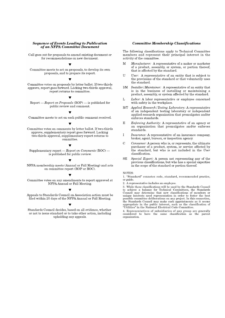
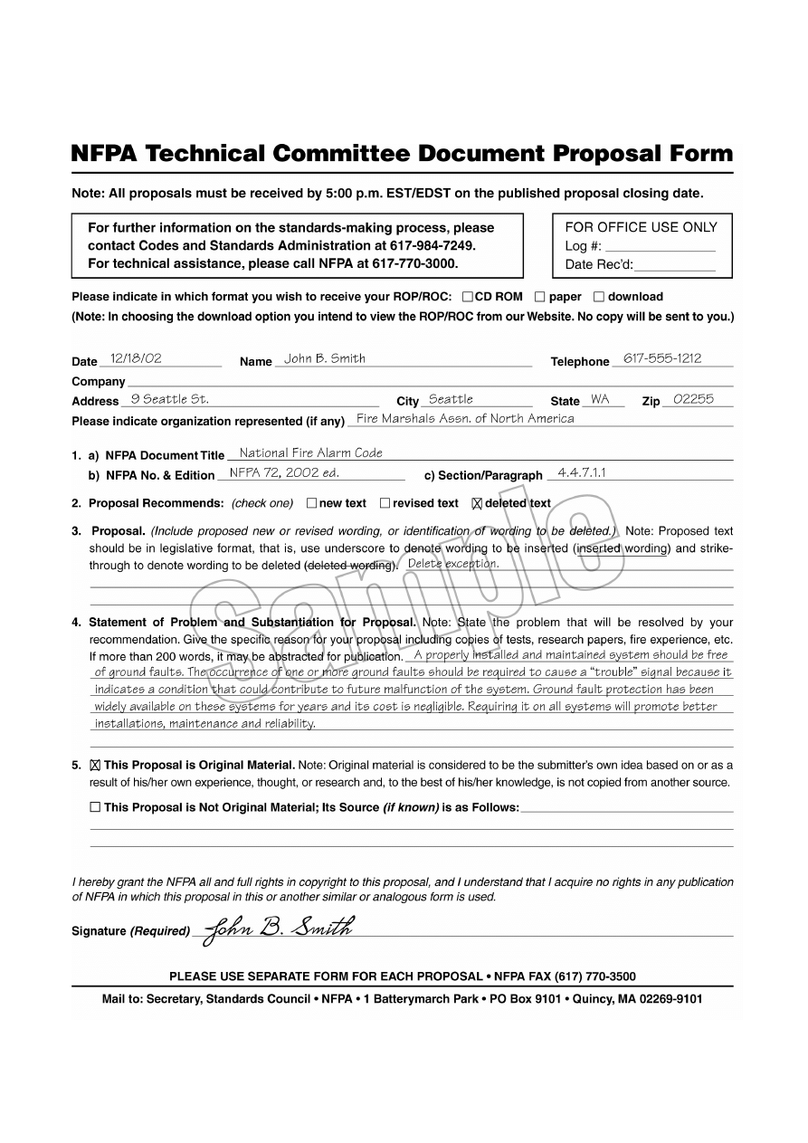

Wyszukiwarka
Podobne podstrony:
CCI Job Interview Workbook 20 w PassItOn and Not For Group Use
Mechanical Pumps For Vacuum Processing
Advisory Committee on the Framework Convention for the Protection of National Minorities Second Opin
DAMIEN JURADO DOLOREAN Traded for Fire bw Ghost of David 7 (Secretly Canadian) SC139sc139
Horn Tom 20 easy recorder duets for children
Call For Fire
Resolution CM ResCMN(2008)1 on the implementation of the Framework Convention for the Protection of
2003 04 luxury for masses
Procedura call for fire
123 Kryć się! Fore, Jay Friedman, Aug 20, 2003
FRAMEWORK CONVENTION for the protection of national minorities, Council of Europe, Straspourg 1995
Intelligent thermoresponsive polymeric stationary phases for aqueous chromatography of biological co
Report Submitted by Spain Pursuant to Article 25, Paragraph 1 of the Framework Convention for the Pr
Advisory Committee on the Framework Convention for the Protection of National Minorities Opinion on
NFPA FIRE PUMPS HANDBOOK
Księga 1. Proces, ART 505(1) KPC, Uchwała z dnia 20 listopada 2003 r
2003 08 20
2003 05 20
więcej podobnych podstron