
10/10 MN05006004Z-EN
replaces 08/07 AWB2786-1593en
User Manual
easy80
0
Data transfer between easy und IEC stations
easyNet
Eaton Corporation
Eaton ist ein führendes Energie-
Management-Unternehmen. Weltweit
ist Eaton mit Produkten, Systemen und
Dienstleistungen in den Bereichen Electrical,
Hydraulics, Aerospace, Truck und
Automotive tätig.
Eatons Electrical Sector
Eatons Electrical Sector ist weltweit führend
bei Produkten, Systemen und Dienstleistungen
zu Energieverteilung, sicherer Stromversorgung
und Automatisierung in der Industrie, in Wohn- und
Zweckbauten, öffentlichen Einrichtungen, bei Energie-
versorgern, im Handel und bei OEMs.
Zu Eatons Electrical Sector gehören
die Marken Cutler-Hammer®, Moeller®,
Micro Innovation, Powerware®, Holec®,
MEM® und Santak®.
www.eaton.com
Eaton Adressen weltweit:
www.moeller.net/address
E-Mail: info-bonn@eaton.com
Internet: www.eaton.com/moellerproducts
www.eaton.comDirecciones de
Eaton en todo el mundo:
www.moeller.net/address
E-Mail: info-bonn@eaton.com
Internet: www.eaton.com/moellerproducts
www.eaton.comIndirizzi EATON
nel mondo:
www.moeller.net/address
4 *patpks#nycmyn*
Rückenbreite 4 – 6 mm (1 Blatt = 0,106 mm für XBS Digitaldruck)
(1 Blatt = 0,080 mm für Eberwein Digitaldruck bei 80 g/m
2
)

All brand and product names are trademarks or registered
trademarks of the owner concerned.
Emergency On Call Service
Please call your local representative:
http://www.eaton.com/moeller/aftersales
or
Hotline After Sales Service:
+49 (0) 180 5 223822 (de, en)
Original Operating Instructions
The German-language edition of this document is the original
operating manual.
Translation of the original operating manual
All editions of this document other than those in German language
are translations of the original German manual.
1
st
edition 2007, edition date 08/07
2
nd
edition 2010, edition date 10/10
© 2007 by Eaton Industries GmbH
Author:
Peter Roersch, Andreas Lüngen
Production: Heidrun Riege
Translator:
Terence Osborn
All rights reserved, including those of the translation.
No part of this manual may be reproduced in any form
(printed, photocopy, microfilm or any other process) or processed,
duplicated or distributed by means of electronic systems without
written permission of Eaton Industries GmbH, Bonn.
Subject to alteration without notice.
Rü
cken
brei
te
f
e
stl
e
g
e
n! (
1
Bl
att = 0,
10
6 mm,
gi
lt
n
u
r für XBS)

10/10 MN05006004Z-EN
1
The easyNet network
5
Configuring stations and the network
– NET_UPDATE function for data exchange
– NET_GET function for fetching data stored
Content

Content
10/10 MN05006004Z-EN
2
IEC station <- IEC/easy station (I/O information)
15
IEC station (Net-ID1) -> Remote I/O station,
e.g. easy800 (I/O information)
IEC station (Net-IDx) <-> EASY223-SWIRE gateway
(I/O information)
– IEC station (Net-IDx) <- EASY223-SWIRE gateway
– IEC station (Net-IDn) -> EASY223-SWIRE gateway
IEC station <-> IEC/easy station
(bit information)
20
IEC station <-> several IEC/easy stations
(double-word data exchange)
22
– PUT function (PUT structure element)
Synchronisation of the real-time clock
Configuring the (easyNet) network
27
Carrying out the configuration
– Configuring with easySoft-CoDeSys
(Net-ID1 = IEC station)
27
– Configuring with easySoft
(Net-ID1 = easy or IEC station)
28
– Configuring via the device display
– Configuring with the Net_Config function
Combination of easyNet with CAN/CANopen
31
– Displaying the loading of the CAN bus
– Monitoring the easyNet telegram
32
Programming via easyNet (Routing)
33
CANopen/easyNet interface
36
– XC200 36
– EC4-200, easy800, MFD-(AC-)CP8
36

10/10 MN05006004Z-EN
3
About this manual
List of revisions
The following are the main changes and amendments which have
been made since the last edition of this manual:
The manual provides the essential information required for the
access of an IEC station, such as an XC200, to other stations in the
easyNet network. The access of the IEC stations is executed by the
program containing the functions for sending and receiving data.
The functions contain structure variables, and both are described
briefly in chapter 2 and chapter 3.
The relationship between the functions and structures, as well as
their integration in the program, are shown in the chapter 4.
The possible data transfer options are described in chapter 2.
This manual is divided into the following chapters:
• The easyNet network
Provides an introduction to the easyNet network,
a chapter 1, page 5.
• Functions
Describes the functions and their properties,
a chapter 2, page 7.
• Structures
Describes the structures, a chapter 3, page 9.
• Application
Shows the possibilities for data transfer between the IEC
stations and easy stations, e.g. easy800, in the form of
examples. The functions and structures are used in these
examples, a chapter 4, page 15.
Additional information on accessing easy stations on the
network is provided in the manuals of the relevant easy
stations.
• Network configuration
Describes how to configure easy stations via the first station
(Net ID 1) on the easyNet, a chapter 5, page 27.
• Combination of easyNet with CAN/CANopen
Provides information on combinations of easyNet – CANopen,
CAN Direct, CAN network variables,
a chapter 6, page 31.
• Routing
Shows the possibility of indirect communication between the
PC and stations via the easyNet, a chapter 7, page 33.
• Bus topology
Shows different topologies, a chapter 8, page 35.
Abbreviations and symbols
Symbols used in this manual have the following meanings:
X
Indicates actions to be taken.
For greater clarity, the name of the current chapter is shown in the
header of the left-hand page and the name of the current section
in the header of the right-hand page. This does not apply to pages
at the start of a chapter and empty pages at the end of a chapter.
Edition date
Page
Description
Change
10/10
all
Change to Eaton notation
j
h
Draws your attention to interesting tips and
supplementary information.

10/10 MN05006004Z-EN
4
10/10 MN05006004Z-EN
5
1 The easyNet network
Network overview
easyNet is based on the CAN network which enables the exchange
of process and system data. It is designed for 8 stations, i.e.
controllers. There are two types of stations that are programmed
differently:
• easy station (programming in the form of a circuit diagram)
– easy800
– MFD-CP8-…
– EASY223-SWIRE (SmartWire gateway without a program,
with a configuration)
• IEC station (programming according to the IEC 1131 standard)
– XC200
– EC4-200
– MFD4
Configuring stations and the network
In easyNet each station has to be configured. In order to identify
each station in the network, each one of them is assigned an
address (Net-ID), as well as parameters that define the behaviour
of the station in the network (e.g. baud rate, SEND IO, Remote
Run). You configure easy stations in the configurator of the
programming software or via the keypad/display on the device.
The IEC stations can be configured individually. The easySoft-
CoDeSys configurator is used to set the communication
parameters and load them with the user program in the stations.
easy stations are configured in the network using easySoft. If a
project contains both easy and IEC stations, both types of station
must be configured in the network.
In easySoft select a symbol for the station in Project View and drag
the symbol onto the Workbench. A general symbol is available
under Net stations for the IEC stations. Position the devices and
enter the communication parameters.
Once you have configured all stations you can load the
configuration onto the easy stations. The configuration and the
program for the IEC stations must be loaded separately with the
easySoft-CoDeSys programming software!
Overview of data transfer
Each station is assigned an ID number 1..8 and can exchange data
with all other stations. Bit, byte, word and double word data
formats are possible. A station with Net-ID = 1 must always be
present. This station handles the management of the
communication on the network. It is the only station that can set
the outputs of the remote I/O stations.
Remote I/O stations are devices, such as an easy800, without a
program.
The data transfer options are described in a chapter
“Functions”, page 7.
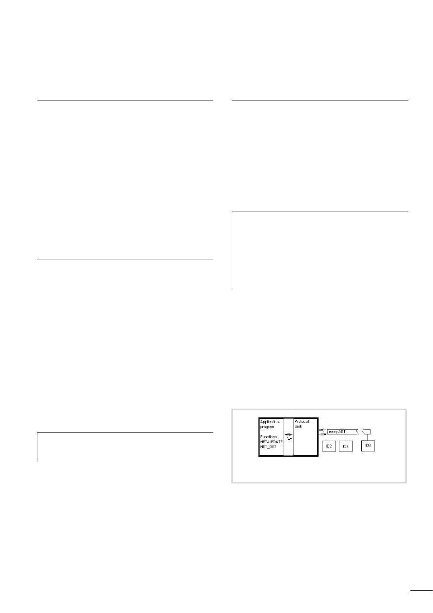
easySoft provides the easy stations with special operands for
sending and receiving data via the network.
IEC stations use the functions of easySoft-CoDeSys for sending and
receiving the data. These functions are contained in the library
SysLibEasyNet.lib. Add this library to the Library Manager in order
to integrate it into the project. Calling the functions in the program
enables the data to be exchanged between the user program and
the protocol task that is invisible to it and which operates
independently to it. The protocol task is a program that handles
the actual data transfer between the IEC station and the individual
stations. It also handles the administrative tasks such as station
monitoring and the support of the routing function.
h
The device at position 1 in Project View is permanently
assigned Net-ID = 1 and must also be the first physical
device on the network line.
h
Further information on data transfer between the easy
stations is provided in the following operating manuals:
• easy800 control relay (MN04902001Z-EN;
previously AWB2528-1423G),
• EASY223-SWIRE (MN05006003Z-EN;
previously AWB2528+1251-1589GB),
• MFD-Titan multi-function display (MN05002001Z-EN;
previously AWB2528-1480GB)
Figure 1: Data transfer between IEC and easy/IEC stations
XC200
EC4-200
MFD4
easy800 MFD
XC200
EC4-200
MFD4

10/10 MN05006004Z-EN
6

10/10 MN05006004Z-EN
7
2 Functions
Data transfer functions
The SysLibEasyNet.lib library provides the functions NET_UPDATE
and NET_GET for sending and receiving the data, as well as
NET_CONFIG for configuring the network. The NET_UPDATE and
NET_GET functions provide the following transfer options:
• NET_UPDATE
– Send output states (bit) of station with Net-ID = 1 to a
station without a program (Remote I/O) (Operand Q/S).
a section “IEC station (Net-ID1) -> Remote I/O station,
e.g. easy800 (I/O information)”, page 16,.
a section “IEC station (Net-IDn) -> EASY223-SWIRE
gateway (I/O information)”, page 19
– Scan input/output states (bit) of each station
(also Remote I/O) (Operand Q/S and I/R).
a section “IEC station <- IEC/easy station (I/O
information)”, page 15,
a section “IEC station (Net-IDx) <- EASY223-SWIRE
gateway (I/O information)”, page 17.
– Exchange bit information between two stations with
programs. The sending station transfers the bit using the
operand SN. The receiving station receives the bit with the
operand RN.
a section “IEC station <-> IEC/easy station (bit
information)”, page 20,
– Put values (DWORD format) onto the network so that they
can be fetched by other stations using the NET-GET function.
a section “IEC station <-> several IEC/easy stations
(double-word data exchange)”, page 22.
• NET_GET
– Get values (DWORD format) from the network that another
station has placed there with the NET_UPDATE function
a section “IEC station <-> several IEC/easy stations
(double-word data exchange)”, page 22.
Description of functions
This section describes the parameters of the functions. Detailed
information and the handling of functions is described in
a chapter “Applications”, page 15.
NET_UPDATE function for data exchange
Function parameters
The return value must be included in the user program (error
output).
Calling the function (example)
Figure 2: NET_UPDATE function
byNetDrvNr
easyNet driver number
(default setting = 0)
pstruNetMain
Pointer to a data structure of type EASY_NET_MAIN
Net_Update
(return value)
TRUE: Function completed successfully.
FALSE: Function aborted with error.
PROGRAM PLC_PRG
VAR
myEASY_NET_MAIN:EASY_NET_MAIN;
(*Declaration local/global possible*)
xResult: BOOL;
END_VAR
xResult:=Net_Update(0 ,ADR(myEASY_NET_MAIN));
h
The NET_UPDATE function must be called once in every
program cycle. The call can only be executed from a task!
NET_UPDATE
BYTE
byNetDrvNr
Net Update
BOOL
POINTER TO EASY_NET_MAIN
pstruNetMain

Functions
10/10 MN05006004Z-EN
8
Description
The NET_UPDATE function enables you to send and receive data.
The function contains the parameter “pstruNetMain” at which
you can set a pointer that points to a variable of type
EASY_NET_MAIN, e.g. “myEASY_NET_MAIN”.
The EASY_NET_MAIN structure and the subsequent structures are
described in a chapter “Structures”, page 9.
NET_GET function for fetching data stored on the network
Function parameters
Calling the function (example)
Description
Calling the NET_GET function enables you to read (get) data from
the network that was placed there by other stations on it using the
EASY_NET_PUT structure. Calling the function only allows you to
“get” one data unit. If several stations have put a data unit on the
network, a station can fetch all data units in succession. The
following scanning options are possible:
• Incorporating the function once in the program and for each
data unit.
The NET-ID of the station and the module number of the data
unit must be specified before every function call.
• Incorporating the function in the program for each data unit.
Each function is assigned a Net-ID and a module number.
All functions are called in one program cycle.
Any number of NET_GET function calls can be executed in one
program cycle.
The function contains the “pstruNetGet” parameter at which you
can set a pointer to the structure EASY_NET_GET and a variable
of type EASY_NET_GET, e.g. “myEASY_NET_GET”.
a section “EASY_NET_GET structure”, page 14.
Figure 3: Access of the user program to easyNet
Figure 4: NET_GET function
byNetDrvNr:
easyNet driver number. Default setting = 0.
pstruNetGet:
Pointer to a data structure of type EASY_NET_GET: This structure is
used for data exchange between the easyNet and the user program
of the station.
Net_Get (return value):
TRUE: Function completed successfully.
FALSE: Function aborted with error.
PROGRAM PLC_PRG
VAR
myEASY_NET_GET : EASY_NET_GET;
xResult:BOOL;
END_VAR
xResult:=NET_GET(0,ADR(myEASY_NET_GET));
NET_UPDATE (function)
easyNet
Application program
EASY_NET_MAIN (structure)
NET_GET
BYTE
byNetDrvNr
Net_Get
BOOL
POINTER TO EASY_NET_GET
pstruNetGet
Figure 5: Get stored data from the network
NET_GET (function)
easyNet
Application program
EASY_NET_GET (structure)

10/10 MN05006004Z-EN
9
3 Structures
EASY_NET_MAIN structure
Structure layout
Structure components
The components of the major structure contain the following
information:
EASY_NET_INFO structure
The states and the status of a station can be interrogated from the
components of a structure. The “aNET_STATE” component
contains an array with an element for each station. An element
contains the state and status of a station.
Structure layout
Structure components
TYPE EASY_NET_MAIN:
STRUCT
INFO: EASY_NET_INFO;
SND: EASY_NET_SND;
RCV: ARRAY [1..8] OF EASY_NET_RCV;
END_STRUCT
END_TYPE
INFO (status information of the stations):
The information is entered in the structure EASY_NET_INFO.
The data is updated when the NET_UPDATE function is called.
SND (send data):
The information must be entered in the structure EASY_NET_SND:
It is transferred with the next call of the NET_UPDATE function.
RCV (receive data):
Array of 8 elements RCV[1, … ,8].
Each element is assigned to a station. The assignment is based on
the element number and the Net-ID of the station (1,…,8), which
are identical.
An element is of structure type EASY_NET_RCV.
The data is updated when the NET_UPDATE function is called.
TYPE EASY_NET_INFO:
STRUCT
byNrOfActiveDevices: BYTE;
byNrOfConfDevices: BYTE;
uiBaudrate: UINT;
byMY_NET_ID: BYTE;
aNET_STATE: ARRAY [1..8] OF EASY_NET_DEVICE;
byError: BYTE;
END_STRUCT
END_TYPE
byNrOfActiveDevices (number of active stations)
byNrOfConfDevices IEC station with Net-ID1 (except XC200):
Number of stations in the configuration list. IEC stations with
Net-ID2, … ,8:
Max. number of stations detected as active at the same time.
uiBaudrate (baud rate in easyNet)
byMY_NET_ID (variable shows the Net-ID of the station)
aNET_STATE (state of the stations):
Array of 8 “aNET_STATE[1,…,8]” elements.
Each element is assigned to a station. The assignment is based on
the element number and the Net-ID of the station (1, … ,8), which
are identical.
An element is of structure type EASY_NET_DEVICE. This structure
stores the current state of the station.
byError (shows the last detected error in easyNet, a table 1).

Structures
10/10 MN05006004Z-EN
10
Table 1:
Possible error codes
The variable “byError” can be reset by setting the send variable
“xAcknowledgeActiveError”.
„xAcknowledgeActiveError“:
A change from FALSE to TRUE sets the “byError” variable to zero.
The system sets the variable back to FALSE after the reset.
EASY_NET_DEVICE structure
Structure layout
Structure components
0x00
No Error.
0xC0
Undefined NET-Device missing.
0xC1
NET-Device 1 missing.
0xC2
NET-Device 2 missing.
0xC3
NET-Device 3 missing.
0xC4
NET-Device 4 missing.
0xC5
NET-Device 5 missing.
0xC6
NET-Device 6 missing.
0xC7
NET-Device 7 missing.
0xC8
NET-Device 8 missing.
0xD0
Daisy-Chain Error.
0xD2
Daisy-Chain Error, too few devices on the NET-Bus
available.
0xD3
Daisy-Chain Error, device with unexpected NET-ID found -
BUS STOPPED.
0xD4
Daisy-Chain Error, device with unexpected NET-ID found,
Net-ID changed - BUS STARTED.
0xE0
CAN-Error.
0xE1
CAN-Error, failed to open CAN-Port. Device stopped.
0xE2
CAN-Error, failed to set Baud-Rate. Device stopped.
0xE3
CAN-Error, not all COB-IDs cold be registered for reading
0xF0
Undefined Error…
Figure 6: Status display of the structure myEASY_NET_MAIN
TYPE EASY_NET_DEVICE:
STRUCT
xDeviceAvailable: BOOL;
xProgram: BOOL;
xRUN: BOOL;
byDelay: BYTE;
END_STRUCT
END_TYPE
xDeviceAvailable:
TRUE = Communication with station possible.
FALSE = Communication with station not possible.
xProgram: BOOL;
TRUE = The station contains a program
FALSE = The station does not contain a program
xRUN: BOOL;
TRUE = The station is in “RUN” mode.
FALSE = The station is in “STOP” mode
byDelay: BYTE;
easy station: Bus delay setting.
IEC station: Always “0”.

10/10 MN05006004Z-EN
EASY_NET_SND structure
11
EASY_NET_SND structure
The EASY_NET_SND structure enables the data to be sent from
the user program to the protocol task. The values of the local
inputs and outputs, including the outputs and inputs of an
expansion module, are entered in the components byQ, byS, wI
and wR.
Structure layout
Structure components
h
The EC4-200 controller does not evaluate these
components.
TYPE EASY_NET_SEND:
STRUCT
byQ:BYTE;
byS:BYTE;
wI:WORD;
wR:WORD;
PUT:EASY_NET_PUT;
aToID:ARRAY[1..8] OF EASY_NET_SNDx;
xStartClockSynchronisation:BOOL;
xAcknowledgeActiveError:BOOL;
END_STRUCT
END_TYPE
byQ:
Local bit outputs Q1 to Q8
(IEC notation = byQ.0 to byQ.7).
The output states are interpreted by all other stations as current
output values.
byS:
Local bit outputs S1 to S8
(IEC notation = byS.0 to byS.7).
The value is set from the user program.
wI:
Local bit inputs I1 to I16
(IEC notation = wI.0 to wI.15).
The input states are interpreted by all other stations as current input
values.
wR:
Local bit inputs R1 to R16
(IEC notation = wR.0 to wR.15).
The value is set from the user program.
PUT:
The PUT component of structure type EASY_NET_PUT enables the
sending of 32 data blocks of 4 bytes each in succession. These data
blocks can be read by another station using a GET function block or
function, a section “IEC station <-> several IEC/easy stations
(double-word data exchange)”, page 22.
aToID:
Array of 8 elements “aToID[1,…,8]“. Each element is assigned to a
station (1,…,8). The receiving station is determined by the element
selected.
Enter the data in the element you wish to send. An element is of
structure type EASY_NET_SNDx.
xStartClockSynchronisation:
A change from FALSE to TRUE starts the synchronisation of the
station clocks to the value of the locally set clock. The
synchronisation is executed on the next full minute. After this is
successfully completed, the variable “xStartClockSynchronisation”
is set to FALSE.
xAcknowledgeActiveError:
A change from FALSE to TRUE sets the “byError” variable to zero.
After the reset, the variable “xAcknowledgeActiveError” is set to
FALSE, a section “EASY_NET_INFO structure”, page 9.

Structures
10/10 MN05006004Z-EN
12
EASY_NET_SNDx structure
Structure layout
Structure components
EASY_NET_PUT structure
The structure allows a data unit/value (DWORD format) to be put
on the network that is fetched from the network by another station
using the NET_GET function. Only one value can be sent.
Structure layout
Structure components
a section “IEC station <-> several IEC/easy stations (double-
word data exchange)”, page 22.
TYPE EASY_NET_SNDx :
STRUCT
byQ:BYTE;
byS:BYTE;
dwSN:DWORD;
END_STRUCT
END_TYPE
byQ/byS:
The sending station must have Net-ID = 1. The receiving station
must be of type Remote I/O!
byQ:
Output bits Q1 to Q8 of the selected station
(IEC notation = byQ.0 to byQ.7).
byS:
Output bits S1 to S8 of the expansion device of the selected station
(IEC notation = byS.0 to byS.7).
dwSN:
32 bits that are sent to the selected station, (IEC notation = dwSN.0
to dwSN.31), a section “IEC station <-> IEC/easy station (bit
information)”, page 20.
h
If you use this structure to send values, only one task
should be used.
TYPE EASY_NET_PUT :
STRUCT
xStartTransfer: BOOL;
byModuleNumber: BYTE;dwData: DWORD;
xTransferPending: BOOL;
xTransferFailed: BOOL;
END_STRUCT
END_TYPE
xStartTransfer:
A change from FALSE to TRUE starts the sending of the data entered
in the “dwData” component.
byModuleNumber:
Module number of the data to be sent (1 to 32).
dwData:
Data unit/value (DWORD format).
xTransferPending:
TRUE = The sending of the data is executed. Another send job
cannot be executed.
FALSE = The send function block is free. A new send job can be
executed.
xTransferFailed:
TRUE = Data transfer faulty.
FALSE = Data transfer ok.
h
If no station accepts the data (NET_GET), no error is
indicated at “xTransferFailed“.

10/10 MN05006004Z-EN
EASY_NET_RCV structure
13
Table 2:
Comparison of the parameters of the structure
EASY_NET_PUT (easySoft-CoDeSys) and the inputs/outputs of
the PUT function block (easySoft)
Put data unit/value on the network
The data unit or value is put on the network after entering the
“byModuleNumber” and “dwData” parameters and a rising edge
at “xStartTransfer“. The output “.xTransferPending” is set
temporarily to TRUE as a feedback signal. A new value can then
be sent.
EASY_NET_RCV structure
The EASY_NET_RCV structure is used by the user program to fetch
the data from the protocol task. The “RCV” structure component
is an array of 8 elements RCV[1,…,8]. The elements are of
structure type “EASY_NET_RCV“. Each element is assigned to a
station (1,…,8) into which the station writes the data. The
received data is scanned by reading out an element such as
“myEASY_NET_MAIN.RCV[2].byQ“.
The data is refreshed with every call of the Net_Update function.
Structure layout
Structure components
a section “IEC station <-> IEC/easy station (bit information)”,
page 20.
Parameter
easySoft
easySoft-CoDeSys
Data
I1
dwData
PUT number
PTxx
byModuleNumber
Strobe
T_
xStartTransfer
Active
AC
xTransferPending
Started
Q1
–
Error
E1
xTransferFailed
TYPE EASY_NET_RCV:
STRUCT
byQ:BYTE;
byS:BYTE;
wI:WORD;
wR:WORD;
dwRN:DWORD;
END_STRUCT
END_TYPE
byQ:
Output bits Q1 to Q8 of the sending station
(IEC notation = byQ.0 to byQ.7).
byS:
Output bits S1 to S8 of the sending station (expansion device) or an
XC200 controller
(IEC notation = byS.0 to byS.7).
wI:
Input bits I1 to I16 of the sending station
(IEC notation = wI.0 to wI.15).
wR:
Input bits R1 to R16 of the sending station (expansion device)
(IEC notation = wR.0 to wR.15).
dwRN:
32-bit data of the sending station
(IEC notation = dwRN.0 to dwRN.31).

Structures
10/10 MN05006004Z-EN
14
EASY_NET_GET structure
Structure layout
Structure components
For this you must have parameterised a variable, such as
“myEasy_Net_Get” of structure type EASY_NET_GET. The
components of the structure contain the following information.
Table 3:
Comparison of the parameters of the NET_GET function
(easySoft-CoDeSys) and the inputs/outputs of the GET
function block (easySoft)
TYPE EASY_NET_GET :
STRUCT
byNET_ID: BYTE;
byModuleNumber: BYTE;
xNewDataReceived: BOOL;
byReceiveCount: BYTE;
dwGet_Data: DWORD;
byError: BYTE;
END_STRUCT
END_TYPE
byNET_ID:
This is where the Net-ID is entered of the station that has put the
data onto the network.
byModuleNumber:
This is where the module number is entered of the data unit to be
fetched.
xNewDataReceived:
TRUE: New data received.
FALSE: No new data present at the specified address. The last data
entered is transferred.
byReceiveCount:
This variable contains the number of telegrams that were received
(cyclical counter that moves back from 16#FF to 16#00).
dwGET_Data:
This contains the received data in a double word.
byError:
0: Data successfully read.
1: Error when reading data.
Parameter
easySoft
easySoft-CoDeSys
Function block number
GTxx
–
Receive data
Qv
dwGet_Data
Module number
PTxx
byModuleNumber
Net-ID of the sending station
NET_ID
byNET_ID
New value present
Q1
xNewDataReceived
Receive counter
–
byReceiveCount
Error
–
byError
10/10 MN05006004Z-EN
15
4 Applications
Data can be sent and received in several ways. The data transfer
depends on the type of station (IEC or easy station) and is
described below. A structure overview here shows the
components of structures that must be parameterised according to
the type of data transferred. The entire structure tree is shown as
it is displayed in online mode in the Status display.
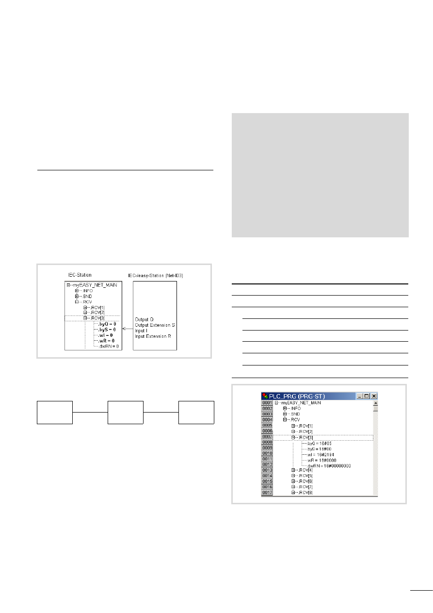
IEC station <- IEC/easy station (I/O information)
An IEC station scans the inputs/outputs (bit data) of IEC or easy
stations, e.g. EC4-200/easy800. The data transfer is cyclical.
The EC4-200 and easy800 stations (also as remote I/O) with their
EASY202-RE or EASY6…-RE/-TE expansion devices provide the bit
data of their local inputs/outputs. They can be scanned by any
station with a user program, including XC200, with the
“Net_Update” function using the “myEASY_NET_MAIN.RCV”
structure.
Example
XC200 scans:
1. the local input 1 of the EC4-200 (Net-ID2),
2. the local input 3 of the easy800 ( Net-ID3).
This requires the following programming:
If in the easy 800 (Net-ID3) the inputs 3, 5, 8, 9 = TRUE and
outputs 1, 3 = TRUE, the status display of the XC200 (Net-ID1) will
show the following structure:
“myEASY_NET_MAIN” structure
Figure 7: Online display: IEC station (Net-ID1) scans the inputs/
outputs of the device (Net-ID3)
XC200
Net-ID1
EC4-200
Net-ID2
easy800
Net-ID3
VAR
myEASY_NET_MAIN: EASY_NET_MAIN;
x1NetID2 :BOOL;
x3NetID3 :BOOL;
END_VAR
Net_Update(byNetDrvNr:=0,
pstruNetMain:=ADR(myEASY_NET_MAIN));
(* read input *)
X1NetID2:=myEASY_NET_MAIN.RCV[2].wI.0;
(*input1 of EC4-200*)
X3NetID3:=myEASY_NET_MAIN.RCV[3].wI.2;
(*input3 of easy800*)
INFO
SND
RCV
RCV[3]
I/O of the easy800 (Net-ID3)
.byQ=16#05
The outputs 1 and 3 are TRUE.
.byS=16#00
The outputs of the expansion (not present).
.wI=16#2194
The inputs 3, 5, 8 and 9 are TRUE.
.wR=16#0000
The inputs of the expansion (not present).
Figure 8: Online status display: IEC station (Net-ID1) scans the
inputs/outputs of the device (Net-ID3)
Applications
10/10 MN05006004Z-EN
16
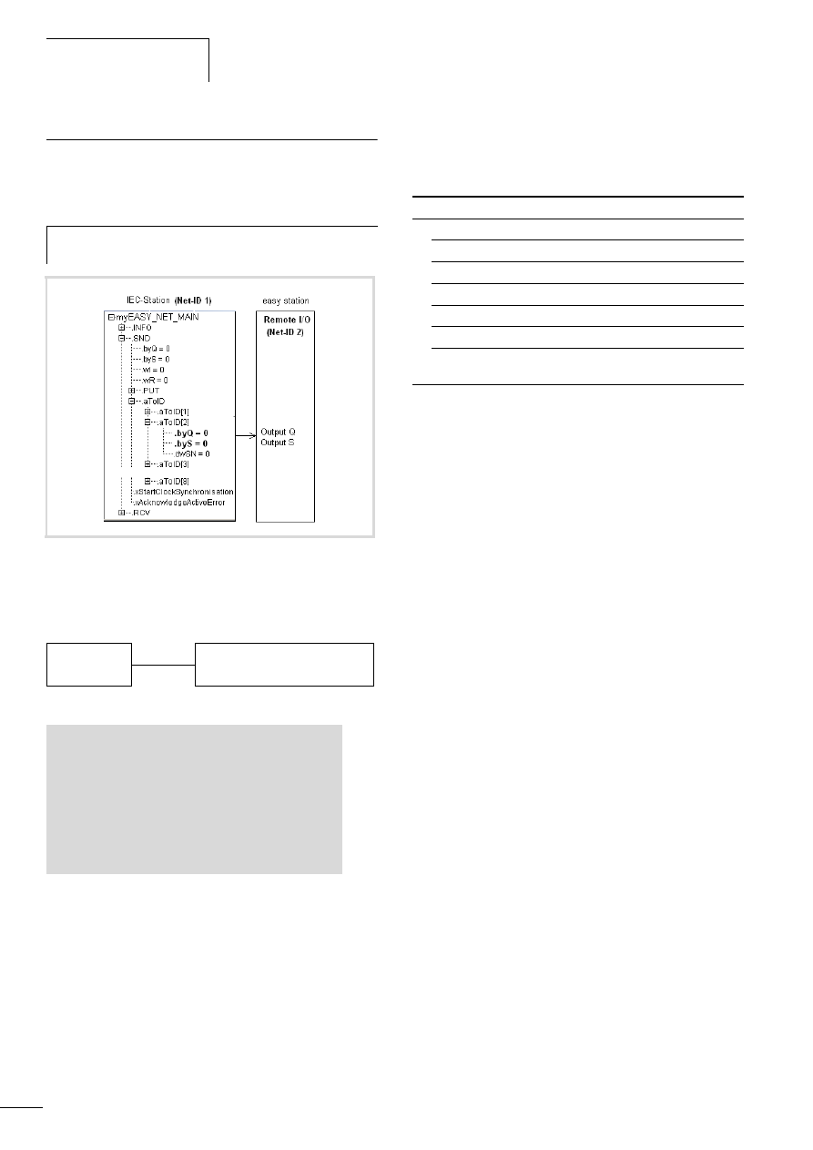
IEC station (Net-ID1) -> Remote I/O station,
e.g. easy800 (I/O information)
An IEC station sets the outputs of a remote I/O station. The data
transfer is cyclical.
Example
The IEC station (Net-ID1) sets the output 3 of the easy800
(Net-ID2).
This requires the following programming:
The following structure for the device (Net-ID 2) is shown in the
status display of the device with station Net-D1:
“myEASY_NET_MAIN” structure
h
Only the station with Net-ID1 can set the outputs of a
remote I/O station, e.g. easy800.
Figure 9: Online display: Set outputs of the remote I/O device
EC4-200 Net-ID1
easy800 Net-ID2 (RemoteI/O)
VAR
myEASY_NET_MAIN: EASY_NET_MAIN;
END_VAR
Net_Update(byNetDrvNr:=0,
pstruNetMain:= ADR(myEASY_NET_MAIN));
(* write Output *)
myEASY_NET_MAIN.SND.aToID[2].byQ.2:=TRUE;
INFO
SND
–
aToID[1]
aToID[2]
Outputs of easy800.
.byQ=16#04
Output 3 (TRUE) is sent to Net-ID2.
.byS=16#00
The outputs of the expansion (not present)
.dwSN=
16#00000000
No function.
10/10 MN05006004Z-EN
IEC station (Net-IDx) <->
EASY223-SWIRE gateway (I/O
information)
17
IEC station (Net-IDx) <-> EASY223-SWIRE gateway
(I/O information)
The data transfer between an IEC station and the EASY223-SWIRE
gateway via the easyNet uses the same functions as between an
IEC station and easy800.
16 modules can be connected to the gateway. A module can send
up to 4 input signals (SI) and one diagnostics signal (SD) to the
gateway. The signals can be scanned by several stations.
A selected station can conversely send two signals (SQ) to a
module via the gateway.
The signals between IEC stations/EASY223-SWIRE and two
SmartWire modules are shown in figure 10. The meaning of the
signals is provided in the module descriptions.
Example
easy-Net connection between IEC station and EASY223-SWIRE.
IEC station (Net-IDx) <- EASY223-SWIRE gateway
(I/O information)
An IEC station scans the input/diagnostics data of the modules.
The data transfer is cyclical.
The inputs/diagnostics inputs of the modules can be scanned by
each station, “a section “IEC station <- IEC/easy station (I/O
information)”.
The “myEASY_NET_MAIN.RCV[2]” structure in figure 11 shows
the allocation between the operands of the IEC station and the
outputs of a SmartWire module. In this example the gateway has
Net-ID 2.
Signal scan of the EASY223-SWIRE
Module no. 1
Module no. 2
etc. up to
Abbildung 10: Data transfer
IEC <-> EASY223-SWIRE <-> Modules
SI = Input signal
SQ = Output signal
SD = Diagnose signal
IEC station
Net-ID1
easyNet
EASY223-SWIRE
(Gateway) Net-ID2
1
2
3
…
16
SmartWire modules
easyNet
IEC station
EASY223-SWIRE SI1
Modul
SmartWire station
1
SI2
SI3
SI4
SD1
SQ1
SQ2
SI1
Modul
SmartWire station
2
SI2
SI3
SI4
SD1
SQ1
SQ2
Figure 11: Scanning of module signals from EASY223-SWIRE
(Net-ID2)
Signal
EASY223-SWIRE
IEC station
Signal meaning
Example SWIRE-DIL
Operand RCV[x]
SI 1
Coil status
.wI.0
SI 2
PKZ
.wR.0
SI 3
No function
.dwRN.0
SI 4
No function
.dwRN.16
SD 1
Diagnostics
.byQ.0
Signal
EASY223-SWIRE
IEC station
Signal meaning
Example SWIRE-DIL
Operand RCV[x]
SI 1
Coil status
.wI.1
SI 2
PKZ
.wR.1
SI 3
No function
.dwRN.1
SI 4
No function
.dwRN.17
SD 1
Diagnostics
.byQ.1

Applications
10/10 MN05006004Z-EN
18
Module no. 8
Module no. 9
etc. up to
Module no. 16
Example
The EC4-200 (Net-ID1) reads the input I1 of module 4 and I1 of
module 11.
This requires the following programming:
Signal
EASY223-SWIRE
IEC station
Signal meaning
Example SWIRE-DIL
Operand RCV[x]
SI 1
Coil status
.wI.7
SI 2
PKZ
.wR.7
SI 3
No function
.dwRN.7
SI 4
No function
.dwRN.23
SD 1
Diagnostics
.byQ.7
Signal
EASY223-SWIRE
IEC station
Signal meaning
Example SWIRE-DIL
Operand RCV[x]
SI 1
Coil status
.wI.8
SI 2
PKZ
.wR.8
SI 3
No function
.dwRN8
SI 4
No function
.dwRN.24
SD 1
Diagnostics
.byS.0
Signal
EASY223-SWIRE
IEC station
Signal meaning
Example SWIRE-DIL
Operand RCV[x]
SI 1
Coil status
.wI.15
SI 2
PKZ
.wR.15
SI 3
No function
.dwRN.15
SI 4
No function
.dwRN.31
SD 1
Diagnostics
.byS.7
EC4-200
Net-ID1
easy223-SWIRE
gatewayNet-ID2
…
4
…
11
…
SWIRE modules
VAR
myEASY_NET_MAIN: EASY_NET_MAIN;
X3NetID2
X10NetID2
END_VAR
Net_Update(
byNetDrvNr=0,
pstruNetMain = ADR(myEASY_NET_MAIN));
(* read input *)
X3NetID2:= myEASY_NET_MAIN.RCV[2].wI.3;
X10NetID2:=myEASY_NET_MAIN.RCV[2].wI.10;

10/10 MN05006004Z-EN
IEC station (Net-IDx) <->
EASY223-SWIRE gateway (I/O
information)
19
IEC station (Net-IDn) -> EASY223-SWIRE gateway
(I/O information)
An IEC station sends output signals to the modules (a example,
page 19). The data transfer is cyclical.
If a SmartWire gateway is integrated in an easyNet network, you
define a station (n) in easySoft which sets the outputs of the
modules that are connected to the gateway.
The structure in the status display of an IEC station shows the
assignment between the operand of an IEC station and the output
of a SmartWire module.
“myEASY_NET_MAIN” structure
Send signals to EASY223-SWIRE
Module no. 1
Module no. 2
etc. up to
Module no. 15
Example
The EC4-200 (Net-ID1) sets the output “SQ1” of module 5 and 14.
This requires the following programming:
h
Only a selected station can set the outputs on one or
several SmartWire gateways.
INFO
SND
–
aToID[1]
aToID[2]
Outputs of the modules of the EASY223-SWIRE
.byQ=16#00
.byS=16#00
.dwSN=
16#00000000
dwSN.0 to dwSN.15 = Output module 1 to 16
(e.g. control of the contactor coils)
Signal
EASY223-SWIRE
IEC station
Signal meaning
Example SWIRE-DIL
Operand aToID[x]
SQ1
Coil
.dwSN.0
SQ2
No function
.dwSN.16
Signal
EASY223-SWIRE
IEC station
Signal meaning
Example SWIRE-DIL
Operand aToID[x]
SQ1
Coil
.dwSN.1
SQ2
No function
.dwSN.17
Signal
EASY223-SWIRE
IEC station
Signal meaning
Example SWIRE-DIL
Operand aToID[x]
SQ1
Coil
.dwSN.15
SQ2
No function
.dwSN.31
EC4-200
Net-ID1
easyNet
easy223 Swire
gateway Net-ID2
…
5
…
14
…
SWIRE module
VAR
myEASY_NET_MAIN: EASY_NET_MAIN;
END_VAR
Net_Update(
byNetDrvNr:=0 ,
pstruNetMain:= ADR(myEASY_NET_MAIN));
(* write Output *)
myEASY_NET_MAIN.SND.aToID[2].dwSN.4:=TRUE;
myEASY_NET_MAIN.SND.aToID[2].dwSN.13:=TRUE;
Applications
10/10 MN05006004Z-EN
20
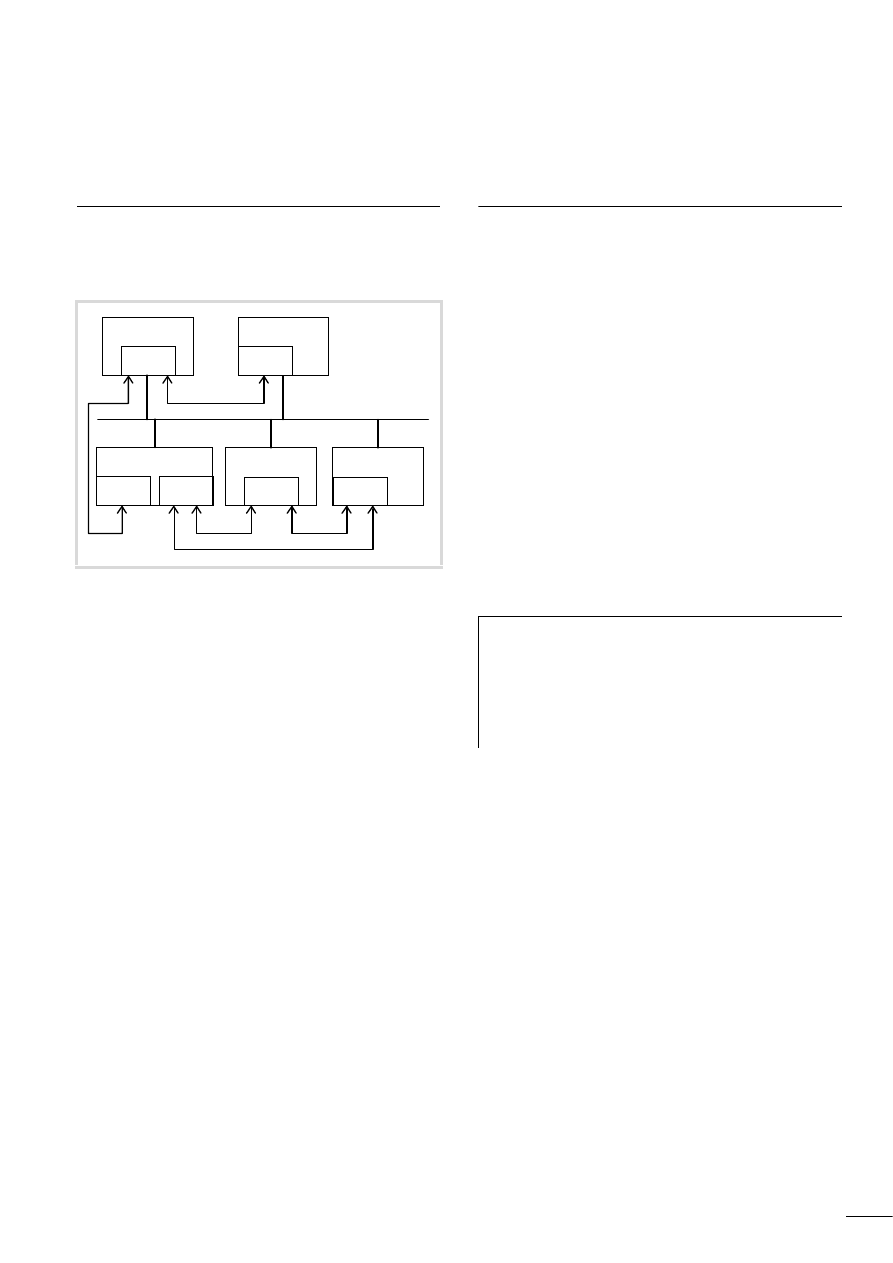
IEC station <-> IEC/easy station
(bit information)
Each station can send a single bit or a data block with up to 32 bits
(SN operand) to another station. These bits are scanned (RN
operand) in the receiving station. The bits, or network markers, are
combined in a 32-bit data block.
Each station has one send and one receive data block
(a figure 12) for communication with the seven other network
stations. The send and receive data blocks are arranged in a one-
dimensional array, consisting of 8 elements. There is a direct
allocation between the send data block of a station and the
receive data block of another station. The position of the data
block in the send array, specified for example on an IEC station in
the aToID structure element, corresponds to the Net-ID of the
receiving station.
The position of the data block in the receive array, which for
example is specified on an IEC station in the RCV structure
component, corresponds to the Net-ID of the sending station.
The data exchange on the bus is cyclical.
Example 1
Transfer IEC station (Net-ID1) -> easy station (Net-ID2).
An IEC station (Net-ID1) is required to send network marker 1
(dwSN.0) or a 32-bit value to the easy station Net-ID2.
Access to the network master is implemented using the data
structure “myEASY_NET_MAIN” with the “.SND.aToID[x].dwSN”
component (double word)
(IEC notation = dwSN.0 to dwSN.31 ).
Figure 12: Overview of data blocks
32
_ _ _
2 1
32
RECEIVE ID
SEND
_ _ _
2
Array
1
6
1
8
7
3
5
4
32
_ _ _
2
Array
1
6
1
8
7
3
5
4
easy800 (Net-ID2)
RECEIVE ID
SEND
32
_ _ _
2 1
32
_ _ _
2
Array
1
32
_ _ _
2 1
32
_ _ _
2
Array
1
6
1
8
7
2
5
4
32
_ _ _
2
Array
1
6
1
8
7
2
5
4
easy800 (Net-ID3)
aTolD SEND
RCV RECEIVE
32
_ _ _
2 1
32
_ _ _
2
Array
1
6
2
8
7
3
5
4
6
2
8
7
3
5
4
IEC station (Net-ID1)
10/10 MN05006004Z-EN
IEC station <-> IEC/easy
station (bit information)
21
The following program is required for the IEC station Net-ID1:
In the easy station (Net-ID2), the individual network marker 1 can
be processed by scanning network marker 1RN1. Or the value can
be scanned by scanning network markers 1RN1 or 1RN32.
Example 2
Transfer IEC station (Net-ID1) <- easy station (Net-ID3).
An IEC station (Net-ID3) is required to transfer the value = 7 (3hex)
to the IEC station (Net-ID1). In the easy station, the network
markers 1SN1,1SN2,1SN3 must be set to TRUE. In the IEC station
(Net-ID1) the structure component “RCV[x].dwRN” (double word)
must be programmed (IEC notation = dwRN.0 to dwRN.31 ).
The following program is required for scanning the value in the IEC
station Net-ID1:
Figure 13: Structure overview, send 32 bits
VAR
myEASY_NET_MAIN: EASY_NET_MAIN;
END_VAR
Net_Update(
byNetDrvNr:=0 ,
pstruNetMain :=ADR(myEASY_NET_MAIN));
(* set dwSN.0 = TRUE*)
myEASY_NET_MAIN.SND.aTo[2].dwSN.0:=TRUE;
or
(* set value = 5 *)
myEASY_NET_MAIN.SND.aToID[2].dwSN:=5;
Figure 14: Structure overview, receive 32 bits
VAR
myEASY_NET_MAIN: EASY_NET_MAIN;
Inpval: DWORD;
END_VAR
Net_Update(byNetDrvNr:=0,
pstruNetMain := ADR(myEASY_NET_MAIN));
(* Demand value *)
Inpval := myEASY_NET_MAIN.RCV[3].dwRN;
Applications
10/10 MN05006004Z-EN
22
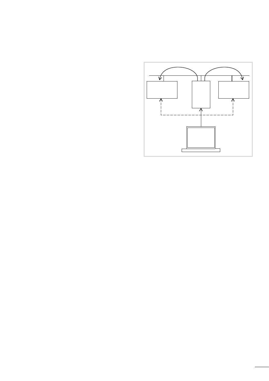
IEC station <-> several IEC/easy stations (double-word
data exchange)
This uses the PUT-GET principle, i.e.
• PUT = Put data unit on the network
• GET = Get data unit from the network.
According to this principle, an IEC station puts onto the network a
data unit (double word) that is identified by a module number (MN
number). For this it uses the PUT (PUT function) which is part of
the NET_UPDATE function.
For this, easy stations use the PUT function block.
The fetching of the data depends on the station type:
• IEC stations fetch the data unit using the NET_GET function,
• Easy stations use the GET function block.
In order to select the data unit, the NET_GET function or the
function block must contain the Net-ID of the sending station and
the module number of the data unit.
The access to the data in the network using the PUT and NET_GET
functions is shown in figure 15.
Two of the stations each use the PUT function to put onto the
network a data unit, identified with the Net-ID number of the
sender and the module number (MN). Net-ID1 has the value 3747,
module number 4, and Net-ID3 the value 4812, module number 6.
The stations (Net-ID3) and (Net-ID4) fetch the data unit 3747 with
the NET_GET function, and station (Net-ID2) fetches the data unit
4812.
The following tables show the functions and function blocks for
sending and fetching the data.
PUT function (PUT structure element)
Each IEC station can use the PUT function to send onto the
network sequential data, identified by the MN/PT numbers
1, 2, … ,32. The data is sent onto the network cyclically via a data
sluice with one data unit sent in each cycle.
Call the NET_UPDATE function to activate the PUT function.
Example
The following program is required for executing the PUT function:
Structure overview of EASY_NET_MAIN with PUT
PUT, of type Easy_Net_PUT, has the following structure:
Figure 15: Example with PUT- and NET_GET functions
IEC station (sender)
Network
IEC station (receiver)
Function:
NET_UPDATE (PUT)
Data
Function:
NET_GET
IEC station (sender)
Network
easy station
(receiver)
Function:
NET_UPDATE (PUT)
Data
Function block:
GET
PUT
PUT
GET
GET
Net-ID 1
Net-ID 2
easyNet
Net-ID 3
Net-ID 4
ID1 MN4 3747
ID3 MN6 4812
Station
Station
Station
Station
easy station (sender)
Network
easy station
(receiver)
Function block:
PUT
Data
Function:
NET_GET
PROGRAM PLC_PRG
VAR
myEASY_NET_MAIN: EASY_NET_MAIN;
END_VAR
Net_Update(
byNetDrvNr:= 0 ,pstruNetMain:= ADR(myEASY_NET_MAIN));
Figure 16: EASY_NET_PUT structure
10/10 MN05006004Z-EN
IEC station <-> several IEC/
easy stations (double-word
data exchange)
23
Executing the PUT function
The following program sequence enables an IEC station to execute
a PUT function.
After entering the parameters “byModuleNumber“ = 4 and
“dwData“ = 3747 and a rising edge at “xStartTransfer” the data
unit is put onto the network. The “.xTransferPending” output is
set momentarily to TRUE as a feedback signal, after which a new
PUT function can be sent.
Figure 17: Program example of the PUT function
h
An error is not indicated for “.xTransferFailed” if no
station receives the data with the NET_GET function.

Applications
10/10 MN05006004Z-EN
24
Example
In order to put data sequentially onto the network, the following program is required:
PROGRAM PLC_PRG (*Program for XC200*)
(*The XC200 sends 3 data telegrams to the network*)
VAR
sEasyNetMain
:EASY_NET_MAIN;
bNetUpdate
:BOOL;
byState
:BYTE;
xNewPUTMsgToTransmit
:BOOL := FALSE;
END_VAR
VAR_INPUT
dwnumb: DWORD;
END_VAR
(*Program*)
dwnumbl:=dwnumb+1;
bNetUpdate:=Net_Update(0, ADR(sEasyNetMain));
IF NOT sEasyNetMain.SND.PUT.xTransferPending AND NOT
sEasyNetMain.SND.PUT.xStartTransfer THEN
(*A new data telegram can be transferred.*)
IF sEasyNetMain.SND.PUT.xTransferFailed THEN
; (* Error on transferring the last data telegram. *)
END_IF
(* In the Case instruction, the values (addressing and data) of the next data telegram to be sent are entered.*)
CASE (byState) OF
0:
(* Application Data Telegram 1*)
sEasyNetMain.SND.PUT.byModuleNumber := 1;
sEasyNetMain.SND.PUT.dwData := dwnumb;
xNewPUTMsgToTransmitt := TRUE; (* ready for send*)
byState:=1;
1:
(* Application Data Telegram 2 *)
sEasyNetMain.SND.PUT.byModuleNumber := 2;
sEasyNetMain.SND.PUT.dwData := 22;
xNewPUTMsgToTransmitt := TRUE; (* ready for send*)
byState:=2;
2:
(* Application Data Telegram 3*)
sEasyNetMain.SND.PUT.byModuleNumber := 3;
sEasyNetMain.SND.PUT.dwData := 33;
xNewPUTMsgToTransmitt := TRUE; (* ready for send*)
byState:=0;
END_CASE
END_IF
IF xNewPUTMsgToTransmit THEN
(* Start of the send operation by setting the Start flag.*)
xNewPUTMsgToTransmit := FALSE;
sEasyNetMain.SND.PUT.xStartTransfer := TRUE;
END_IF
IF sEasyNetMain.SND.PUT.xTransferPending THEN
(* The data transfer is active, Start flag can be reset.*)
sEasyNetMain.SND.PUT.xStartTransfer := FALSE;
END_IF
10/10 MN05006004Z-EN
IEC station <-> several IEC/
easy stations (double-word
data exchange)
25
The NET_GET function
Calling the NET_GET function enables you to read (get) data from
the network that was placed there by other stations on it using the
PUT function. Calling the function only allows you to “get” one
data unit.
Call the NET_GET function to activate the function of the same
name.
Example
The following program is required for executing the NET_GET
function:
The structure of EASY_NET_GET is shown in the following online
display:
Executing the NET_GET function
The following program sequence enables an IEC station to execute
a NET_GET function.
After the parameters for the “byNET_ID” = 1 and
“byModuleNumber” = 4 components are set, a cyclical call of the
NET_GET function is initiated. The “xNewDataReceived” variable
must be scanned continuously. If the variable is TRUE, a new data
unit is received. It is presented at the “dwData” component.
Example
Fetching several modules from the network.
With the following program for an EC4-200, Net-ID2, the modules
1, 2 and 3 are fetched from the network that are put there by the
station with Net-ID1.
PROGRAM PLC_PRG
VAR
myEasyNetGet : EASY_NET_GET;
END_VAR
NET_GET(0,ADR(myEasyNetGet));
Figure 18:EASY_NET_GET structure
Figure 19: Program example of the NET-GET function

Applications
10/10 MN05006004Z-EN
26
Synchronisation of the real-time clock
The real-time clocks of all easyNet stations can be set to the
current time of the local real-time clock. This synchronisation can
be carried out very simply.
The SND area of the “myEASY_NET_MAIN” data structure
contains the variable “xStartClockSynchronisation“. A change
from FALSE to TRUE starts the synchronisation of the clocks to the
value of the locally set clock. The synchronisation is executed on
the next full minute. After this is successfully completed, the
variable “xStartClockSynchronisation” is set automatically to
FALSE.
PROGRAM PLC_PRG
VAR
myEasyNetGet: EASY_NET_GET;
bNetUpdate: BOOL;
byState: BYTE;
xSuccess: BOOL;
RecData: DWORD;
xReceive: BOOL;
Errorflag: BYTE;
RecData1: DWORD;
RecData2: DWORD;
RecData3: DWORD;
END_VAR
IF xReceive = FALSE THEN
CASE (byState) OF
0:
myEasyNetGet.byModuleNumber := 1;
myEasyNetGet.byNet_ID := 1;
xReceive := TRUE;
byState:=1;
1:
myEasyNetGet.byModuleNumber := 2;
myEasyNetGet.byNet_ID := 1;
xReceive := TRUE;
byState:=2;
2:
myEasyNetGet.byModuleNumber := 3;
myEasyNetGet.byNet_ID := 1;
xReceive := TRUE;
byState:=0;
END_CASE
END_IF
(* GET data…*)
xSuccess:=Net_Get(0, ADR(myEasyNetGet));
IF xSuccess AND xReceive THEN
IF myEasyNetGet.xNewDataReceived THEN
IF myEasyNetGet.xNewDataReceived THEN
IF byState = 1 THEN
RecData1:=myEasyNetGet.dwGet_Data;
END_IF
IF byState = 2 THEN
RecData2:=myEasyNetGet.dwGet_Data;
END_IF
IF byState = 0 THEN
RecData3:=myEasyNetGet.dwGet_Data;
END_IF
xReceive:=FALSE;
END_IF
ELSE
Errorflag:=myEASYNetGet.byError;
END_IF
Figure 20: Data structure for the synchronisation of the real-time clock
10/10 MN05006004Z-EN
27
5 Configuring the (easyNet) network
The easy station (Net-ID = 1) enables you to configure all other
stations on the network, such as easy800, MFD-CP8-… and EC4P.
The stations addressed with Net-ID 2,…,8 are assigned the
communication parameters such as Net-ID, baud rate, bus delay
and Send IO. The station with Net-ID1 can be an EC4-200 or an
easy station such as easy800 or MFD-CP8-…
Requirements for the configuration:
• The network cannot contain an XC200.
If the network contains an XC200 each station must be
configured separately!
• The network line must not have any spur lines.
• The stations must be suítable for network configuration.
• If an IEC station is to be configured via the network, it must
contain a project in which the easyNet function is activated.
• The executing station must have Net-ID = 1 and be located at
the start of the line (position 1).
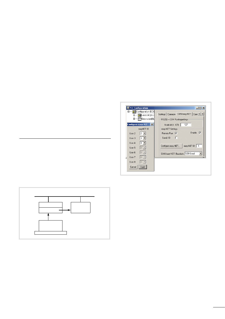
Carrying out the configuration
The configuration is carried out in two steps:
1. Create the configuration (enter the communication
parameters),
2. Transfer parameters to the individual stations.
Configuring with easySoft-CoDeSys
(Net-ID1 = IEC station)
1. Enter communication parameters
Enter in the easySoft-CoDeSys programming software the
parameters for all stations.
X
In the programming software call up the PLC configurator.
X
Select the “CAN/easyNET” tab.
X
Add a tick to the “Activate” field in the “easyNET settings”
area.
X
Add a 1 in the “easyNET-ID” field.
X
Activate/deactivate the functions Remote Run (Net-ID = 2 … 8)
and Send I/O.
Assign the other stations with a Net-ID:
X
Click the “Configure easy-NET” button and select the Net-IDs
for the stations, as shown in figure 22.
The activated/deactivated functions “Remote Run” and
“Send I/O” apply to all selected stations.
X
Enter the baud rate in the CAN/easy-NET Baud rate field.
Create the user program and include the NET_CONFIG function,
a section “Configuring with the Net_Config function”, page 29.
2. Transferring the parameters to the individual stations
with the NET_CONFIG software function
Transfer the project to the station with Net-ID =1. After the station
is started, the NET_CONFIG function handles the transfer of the
parameters to the individual stations.
Figure 21: Network configuraton via PC (easySoft-CoDeSys)
easyNet
Net-ID1
Net-ID2
IEC station
easy-/
IEC station
NET_CONFIG
easySoftCoDeSys
PC
Figure 22: Entering parameters and specifying station Net-IDs
Configuring the (easyNet)
network
10/10 MN05006004Z-EN
28
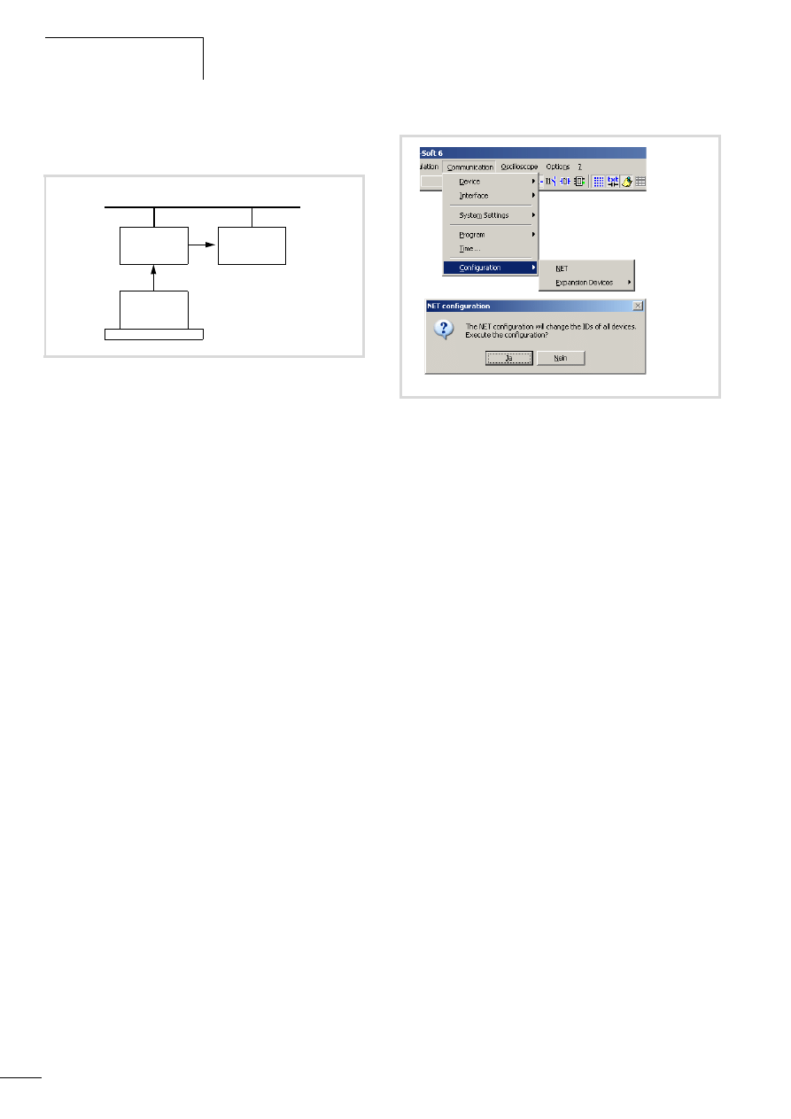
Configuring with easySoft
(Net-ID1 = easy or IEC station)
Create the entire network with the communication parameters for
the individual stations in the easySoft programming software.
Connect the PC to the station with Net-ID1. Start the transfer of
the parameters from the PC to the individual stations via the menu
command Communication-> Configuration -> NET.
Requirement:
• First of all load the station with the Net-ID1 with its program
and configuration containing the Net-ID = 1 setting.
• If an IEC station is to be assigned Net-ID1, the easyNet setting
must also be activated, a section “Configuring with
easySoft-CoDeSys (Net-ID1 = IEC station)”, page 27.
• Using easySoft, it is then possible to access station Net-ID1 and
configure the other stations via this device.
1. Enter communication parameters
If you have placed the stations in easySoft in the Project tab, each
station will have been assigned a Net-ID on the basis of its position
on the line or as you have specified.
You can only enter parameters such as Remote-RUN and
Sende I/O after a station has been selected.
2. Transferring the parameters and assigning Net-IDs
X
Connect the PC with the station Net-ID1.
X
Select online mode.
X
Click the NET button via Communication -> Configuration.
X
Answer the question in the Configuration NET window with
‘yes’ in order to load the parameters including the Net-ID to all
stations.
Configuring via the device display
If you are using an easy800, MFD-CP8-… or EC4-200 with a
display you can also enter the parameters via the display.
Requirement:
• You have transferred NET-ID = 1 and the baud rate to the
device.
• You complete the configuration when you answer ‘ok’ to the
question “configure?” in CONFIGURATOR -> NET ->
CONFIGURE.
Figure 23: Network configuraton via PC (easySoft)
easyNet
Net-ID1
Net-ID2
easy-/
IEC station
easy-/
IEC station
easySoft
PC
Figure 24: Carrying out the configuration, menu overview

10/10 MN05006004Z-EN
Carrying out the configuration
29
Configuring with the Net_Config function
The function is contained in the library SysLibEasyNet.lib.
Description
This function enables the stations to be configured.
A rising edge at the “xConfigStart” input starts the function. You
can monitor the process by checking the feedback values.
Call the Net_Config function in a separate program section which
is run only on request (configuration request).
Inputs of the function
• xConfigStart:
A rising edge (FALSE->TRUE) starts the function.
• xOverwriteWrongIDs:
If stations are connected in a network that already have an
address, the user can use TRUE/FALSE at this input to set
whether the existing addresses are to be retained or changed.
– TRUE:
Stations already with an address are assigned the addresses
of the configuration.
– FALSE:
The existing addresses and the order of the stations are
compared with the configured addresses and order. If they
are not the same, the configuration is not carried out and an
error message (0xFE) is output at the output variable.
• Output variables of the Net_Config function:
– 0x00(0): No action
– 0x01(1): Configuration completed properly
– 0x02(2): Configuration is being carried out
– 0xFF(-1): Station that is to carry out the configuration does
not have Net-ID = 1,
the address sequence is incorrect
– 0xFE(-2): Net-ID conflict
– 0xFD(-3): Timeout error, no answer from the addressed
station
– 0xFC(-4): Number of existing stations is more than that of the
configured stations
– 0xFB(-5): easyNet not active
Example
Programming the Net-Config function.
Figure 25: NET_CONFIG function
h
Observe the configuration requirements a section
“Configuring with easySoft-CoDeSys (Net-ID1 = IEC
station)”, page 27!
NET_CONFIG
xConfigStart: BOOL
Net_Config: BYTE
xOverwriteWrongIDs: BOOL
Program NETConfig
VAR
xStartAutoconfig
AT%IX0.0
:BOOL;
xOverwriteWrongIDs
AT%IX0.1
:BOOL;
xConfigStart
:BOOL:=FALSE;
xConfigurationDone
:BOOL:=FALSE;
siStateOf Autoconfig
:SINT;
siErrorCode
:SINT;
fbTriggerConfig
:R_TRIG;
END_VAR
fbTriggerConfig(CLK:=xStartAutoconfig );
IF fbTriggerConfig.Q AND siStateOfAutoconfig = 0 THEN
xConfigStart:= TRUE;
xConfigurationDone:= FALSE;
siErrorCode:= 0;
END_IF
siStateOfAutoconfig := Net_Config
(xConfigStart, xOverwriteWrongIDs);
CASE siStateOfAutoconfig OF
0:(* Waiting for start of configuration *)
; (* Do nothing *)
1:(* Configuration successfully terminated *)
xConfigurationDone := TRUE;
xConfigStart := FALSE;
2:(* Configuration pending*)
; (* Do nothing *)
ELSE
(* Configuration done with error *)
siErrorCode := siStateOfAutoconfig;(* Error handling *);
xConfigStart := FALSE;
END_CASE

10/10 MN05006004Z-EN
30
10/10 MN05006004Z-EN
31
6 Combination of easyNet with CAN/CANopen
Combination possibilities
The combination of easyNet with CAN (different types) via a bus is
always possible. Some rules must be observed depending on the
CAN communication.
• easyNet and CANopen
Simultaneous use of easyNet and CANopen causes only the
following Node-IDs to be available for the CANopen stations:
– Node-IDs: 9…12; 16; 25…32.
– A use of other Node-IDs may cause collisions with easy
stations.
• easyNet and CAN Direct
1)
If easyNet is used with CAN Direct, the following COB-ID ranges
are available (COB = Communication Object) COB-IDs 0x1:
– 0x7f for high-priority CAN telegrams 0x781;
– 0x7FF low-priority CAN telegrams.
• easyNet and CAN network variables
1)
In order to use easyNet and CAN network variables
simultaneously, the following COB-ID ranges are available
(COB =Communication-Object) COB-IDs 0x1:
– 0x7f for high-priority CAN telegrams 0x781;
– 0x7FF low-priority CAN telegrams.
1) When using CAN Direct and CAN network variables at the same time,
the COB-IDs must not overlap.
Notes on operation
Controlling bus load
In an easyNet network the stations control the bus load. This
ensures the transfer of all messages.
The bus load is higher in a CAN/CANopen network and in a
combination of easyNet and CAN/CANopen than in an easyNet
network. In this case, the parameter “SendIO/xSendIO” must be
deactivated on every easy station so that the bus load can be
reduced.
In order to further reduce the bus load, you can increase the bus
delay time between the transfer cycles of user data for an easy
station. Raise the Bus Delay parameter on the Communication
Parameters tab in the easySoft Project View. The value 1 means
that the bus delay time is doubled, value 15 means that the bus
delay is increased by the factor of 16, see easySoft Online Hep ->
Configuration of the Network.
To ensure proper data exchange, the bus load must not exceed
75 %.
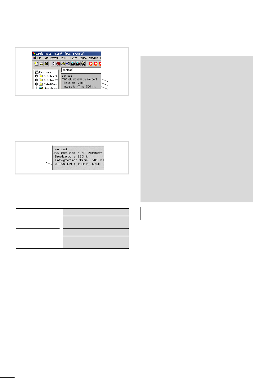
Displaying the loading of the CAN bus
The user can check the bus load in easySoft-CoDeSys using the
“canload” browser command.
The PLC browser command “canload” belongs to the
“XC200_Util.lib” library. It indicates the loading of the CAN bus.
Display examples a fig. 27 and fig. 28, page 32.
Figure 26: Data transfer possibilities in easyNet, CAN, CANopen
network
1) CANopen, CAN Direct, CAN network variables.
2) easyNet.
XC200
Node-ID
10
easy800
EC4-200
Node-ID
11
Node-ID
9
Net-ID1
Net-ID2
easy800
Net-ID3
1)
1)
2)
2)
2)
easyNet/CAN/CANopen
h
With routing, i.e. access from the PC to a target station
(not to the station that is connected to the PC), remember
that an additional bus load of 15 % is possible.
Try to achieve as even a bus utilisation as possible.
Program the stations so that they cannot send the data at
the same time!
Combination of easyNet with
CAN/CANopen
10/10 MN05006004Z-EN
32
Table 4:
Possible alarm messages
Monitoring the easyNet telegram
With an XC200 or EC4-200 controller, the following example
program enables the reception of easyNet telegrams to be
monitored. A loss of a telegram by the controller or the overflow
of a receive buffer can be detected by the user program. In this
case one of the two parameters
“CAN_GET_HW_OVERFLOW_COUNT” or
“CAN_GET_QUEUE_OVERFLOW_COUNT” is greater than 0. The
bus load must be reduced in order to prevent telegram loss.
In order to create the program, the library “SysLibCan.lib” must be
incorporated. The “dwHandle” parameter must be entered
according to the station type:
• A XC200 requires a “5“,
• a EC4-200 requires a “6“.
Program for monitoring telegrams:
Figure 27: Loading of the CAN bus (Example 1)
a Loading of the CAN bus in the last integration interval.
b Current baud rate of the CAN bus
c Time of the integration interval.
The integration time is set by default to 500 ms and can't be
changed via the browser.
Figure 28: Loading of the CAN bus with warning message
(Example 2)
a Warning message, a table 4
Alarm message
Meaning
ATTENTION: HIGH
BUSLOAD
Loading of the CAN bus f 75 %
CAN bus not activated
The CAN bus is not active
CAN-Busload =
Invalid Calculation
Monitoring of the bus load has failed
c
b
a
a
PROGRAM PLC_PRG
VAR
MyNetMainStruct : EASY_NET_MAIN;
iHwOverflowCount: INT := 0;
iQueueOverflowCount: INT :=0;
END_VAR
VAR CONSTANT
dwHandle_XC200:DWORD:=05;
dwHandle_EC4-200:DWORD:=06;
END_VAR
iHwOverflowCount:= SysCanControl(
dwHandle:=dwHandle_XC200,
wFunction:=CAN_GET_HW_OVERFLOW_COUNT,dwParam := 0);
iQueueOverflowCount:= SysCanControl(
dwHandle := dwHandle_XC200,
wFunction := CAN_GET_QUEUE_OVERFLOW_COUNT,dwParam := 0);
IF iHwOverflowCount > 0 OR iQueueOverflowCount > 0 THEN
; (*Telegram lost.*)
END_IF
(* General bus access *)
Net_Update(ByNetDrvNr:=0 ,
pstruNetMain:= ADR(MyNetMainStruct));
h
The parameter “CAN_GET_HW_OVERFLOW_COUNT”
for the XC200 is available from hardware version 5 (V05).
10/10 MN05006004Z-EN
33
7 Programming via easyNet (Routing)
“Routing” is the ability to establish an online connection from a
programming device (PC) to any desired (routing capable) station
in an easyNet network, without having to directly connect the
programming device with the target station. It can be connected
to another station in the network.
The routing connection enables you to carry out all the operations
that are also possible with a direct online connection between the
programming device and the station:
• Program download
• Online modifications
• Program test (Debugging)
Routing offers the benefit of being able to access all routing
capable stations on the easyNet from any station which is
connected with the programming device. This makes it possible to
operate remotely configured stations easily.
However, the data transfer rate with routing connections is
considerably slower than with direct connections (serial or TCP/IP).
This will result in slower refresh times for visualisation elements
(variables) or slower download speeds.
The following requirements must be fulfilled in order to use
routing:
• Both the routing station and the target station must support
routing.
• Both stations must be connected via the bus.
• The stations must have the same active bus baud rate.
The routing options available are listed in the following fig. 29.
If you connect the PC to a station, you can establish a connection
to another station via the easyNet.
Establish the connection via one of the programming interfaces of
the station, e.g. RS232, USB or Ethernet.
X
In easySoft first click the Communication button and then
Connection.
X
Select the interface:
– Ethernet:
Under the Ethernet profiles heading click the Edit button and
enter the IP address, such as 192.168.119.200. Port = 10001
– COMx:
Select an interface and the baud rate (standard baud rate of
the IEC stations: 38400 bits/s of easy stations 19200 bits/s).
– COM3 (USB) only EC4-200
X
Click on the Online button.
The PC is connected with the station. To establish the
connection to the target station, it must have a configuration
with a Net-ID.
X
Under Device select a target station with which you wish to
communicate.
Figure 29: Routing options
EC4-200
easyNet
Net-ID
Net-ID
1
2
3
Net-ID
easy800
Remote I/O
IEC-/
easy
Station
PC
easySoft
Programming via easyNet
(Routing)
10/10 MN05006004Z-EN
34
In online mode you can then carry out the functions in the
operating fields:
If you have selected an easy station as target station you can carry
out a program download (click the PC -> Device button) or change
parameters.
You can change the following parameters:
Transfer the new settings to the stations in the following way:
X
First click Communication l Program button and then the
PC => Device button.
X
The settings can be read from the PLC by clicking the Device =>
PC button.
The routing options are also available if you configure an easy
station with Net-ID1 and an IEC station with Net-ID2, as in
figure 31, page 34. If you then select the IEC station as target
station, you can carry out the following operations with the IEC
station after the easySoft communication menu is called:
• Start/stop,
• Set time
• Allow display of device information.
Figure 30: Program download in online mode
Field
Function
Time
Set the local time and synchronise the device times
in the network.
Program
Change between RUN and STOP.
Display
View the status of the easy-NET variables and the
device information.
Baud rate
In the Project menu in the network overview
Bus delay
REMOTE RUN
Depending on the PLC selected in the
Communication parameter tab l NET
Configurator
Send IO
NET-ID
Figure 31: Routing via easy station Net-ID1 to the IEC station Net-ID2
easyNet
Net-ID1
Net-ID2
easy-/
IEC station
easy-/
IEC station
easySoft
PC
10/10 MN05006004Z-EN
35
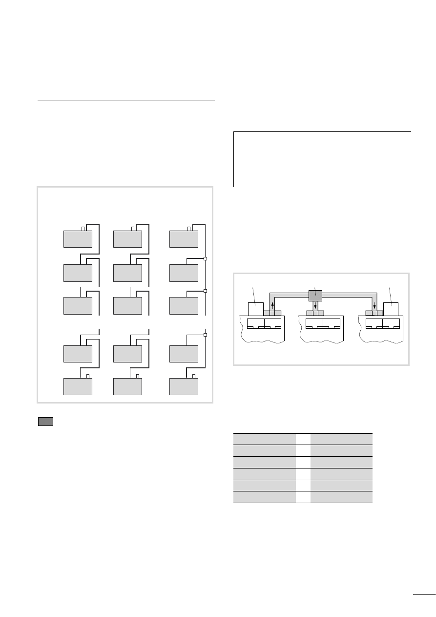
8 Bus topology
Overview
A linear topology with optional stub lines can be implemented for
the bus topology. The ends of the bus must be terminated by bus
terminating resistors (120 O).
To transfer the data on easyNet you can set one of the baud rates
of 50 Kbit/s or 125 Kbit/s on the XC200. The baud rate must be
adapted at the other stations so that all stations communicate
with the same baud rate.
Example 1
Geographical position same as Net-ID
Stations: EC4-200, easy800,MFD-CP8, MFD-AC-CP8
Network configuration possible
Example 2
Geographical position not same as Net-ID
Stations: EC4-200, easy800,MFD-CP8, MFD-AC-CP8
Network configuration possible
Example 3
Geographical position same or not same as Net-ID
Stations: EC4-200, easy800,MFD-CP8, MFD-AC-CP8, XC200
Network configuration possible, configure devices individually
The station at the physical location 1 is always assigned Net-ID =
1. The 7 other stations are connected to this station via the
easyNet.
The IEC stations that have two easyNet connections with the
signal cables (SEL_IN/SEL_OUT) can be incorporated as in the
easyNet, a fig. 32.
If you connect the stations as shown in figure 32, example 3, you
must connect the connection cable between the stations and the
T connectors as follows:
The easyNet stations have one input and one output channel for
connecting to the easyNet. The bus cable is connected to the
station with Net-ID 1 on the output channel and via the
T connectors to which the input channels of the other stations are
connected.
Table 5:
Signal connection between the stations
n = 1..8
Figure 32: PLC connection options
easy/IEC station
1
2
3
X
7
8
1
2
3
X
7
8
1 (1)
2 (3)
3 (4)
X
7 (6)
8 (5)
1
3
4
X
6
5
Example 1
Example 3
Po
sitio
n
NET-ID
Example 2
NET-
ID
NE
T-
ID
h
The XC200 has two CAN/easy-NET interfaces in one plug
connector. Unlike other devices, however, it does not
have a signal cable (SEL_IN/OUT)!
The cables of both interfaces are internally connected
with each other. They can be incorporated into the
network as shown in fig. 32, example 3.
Figure 33: easyNet network with T connector
a Bus termination resistor
b T connector
c Bus termination resistor
IEC station
t easy station
ECAN_H
ECAN_H
ECAN_L
ECAN_L
GND
GND
SEL_IN (Net-IDn)
SEL_OUT (Net-IDn-1)
SEL_OUT (Net-IDn)
SEL_IN (Net-IDn+1)
Net-ID 1
easy800
1 o NET O 2
1 o NET O 2
1 o NET O 2
Net-ID 2
easy800
Net-ID 3
easy800
a
b
c
Bus topology
10/10 MN05006004Z-EN
36
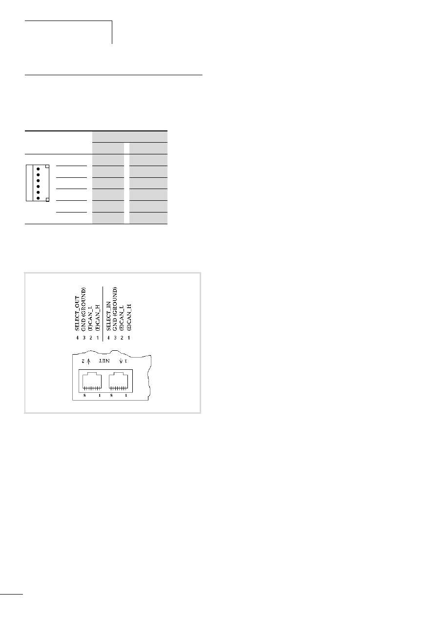
CANopen/easyNet interface
XC200
Table 6:
Assignment of the CANopen/easyNet interface of the XC200
EC4-200, easy800, MFD-(AC-)CP8
Terminal
Signal
CANopen
easyNet
6
GND
GND
5
CAN_L
ECAN_L
4
CAN_H
ECAN_H
3
GND
GND
2
CAN_L
ECAN_L
1
CAN_H
ECAN_H
Terminals 1 and 4, 2 and 5, 3 and 6 are internally
connected.
Figure 34: CAN/easyNet interfaces
6
5
4
3
2
1

10/10 MN05006004Z-EN
37
Index
Address Net-ID . . . . . . . . . . . . . . . . . . . . . . . . . . . . . . . 5
Baud rate (easyNet) . . . . . . . . . . . . . . . . . . . . . . . . . . . 35
Bit inputs . . . . . . . . . . . . . . . . . . . . . . . . . . . . . . . . . . . 11
Bit outputs . . . . . . . . . . . . . . . . . . . . . . . . . . . . . . . . . . 11
Bus terminating resistors (easyNet) . . . . . . . . . . . . . . . 35
Bus topology (easyNet) . . . . . . . . . . . . . . . . . . . . . . . . 35
C
CAN
CANopen . . . . . . . . . . . . . . . . . . . . . . . . . . . . . . . 31
Direct . . . . . . . . . . . . . . . . . . . . . . . . . . . . . . . . . . 31
Interface . . . . . . . . . . . . . . . . . . . . . . . . . . . . . . . . 36
Network variable . . . . . . . . . . . . . . . . . . . . . . . . . 31
canload . . . . . . . . . . . . . . . . . . . . . . . . . . . . . . . . . . . . 31
COB-ID . . . . . . . . . . . . . . . . . . . . . . . . . . . . . . . . . . . . 31
Communication parameters . . . . . . . . . . . . . . . . . . . 5, 27
Communication-Object . . . . . . . . . . . . . . . . . . . . . . . . 31
Connection establishment (PC – PLC) . . . . . . . . . . . . . 33
via easyNet . . . . . . . . . . . . . . . . . . . . . . . . . . . . . . . 5
Debugging . . . . . . . . . . . . . . . . . . . . . . . . . . . . . . . . . . 33
disk_sys . . . . . . . . . . . . . . . . . . . . . . . . . . . . . . . . . . . . . 8
Displaying device information (easyNet) . . . . . . . . . . . 34
E
easy-NET
Interface . . . . . . . . . . . . . . . . . . . . . . . . . . . . . . . . 36
easyNet
Expansion . . . . . . . . . . . . . . . . . . . . . . . . . . . . . . . . . . 15
Flash . . . . . . . . . . . . . . . . . . . . . . . . . . . . . . . . . . . . . . . 8
Gateway EASY223-SWIRE . . . . . . . . . . . . . . . . . . . . . . 17
GET function block . . . . . . . . . . . . . . . . . . . . . . . . . . . . 14
Input bits . . . . . . . . . . . . . . . . . . . . . . . . . . . . . . . . . . . 13
Interface
Library . . . . . . . . . . . . . . . . . . . . . . . . . . . . . . . . . . . . . . 5
Linear topology (easyNet) . . . . . . . . . . . . . . . . . . . . . . 35
NET_GET function . . . . . . . . . . . . . . . . . . . . . . . . . . . . 22
Net-ID . . . . . . . . . . . . . . . . . . . . . . . . . . . . . . . . . . . . . . 5
Network
Configuring easyNet . . . . . . . . . . . . . . . . . . . . . . . 27
Markers . . . . . . . . . . . . . . . . . . . . . . . . . . . . . . . . 20
Online modifications . . . . . . . . . . . . . . . . . . . . . . . . . . 33
Outputs bits . . . . . . . . . . . . . . . . . . . . . . . . . . . . . . . . . 12
P
Program
Test . . . . . . . . . . . . . . . . . . . . . . . . . . . . . . . . . . . . 33
Programm
Download . . . . . . . . . . . . . . . . . . . . . . . . . . . . . . . 33
Protocol task . . . . . . . . . . . . . . . . . . . . . . . . . . . . . . . . . 5
PUT function . . . . . . . . . . . . . . . . . . . . . . . . . . . . . . . . 22
PUT function block . . . . . . . . . . . . . . . . . . . . . . . . . . . . 12
Receive data . . . . . . . . . . . . . . . . . . . . . . . . . . . . . . . . . 9
Send data . . . . . . . . . . . . . . . . . . . . . . . . . . . . . . . . . . . 9
Spur line . . . . . . . . . . . . . . . . . . . . . . . . . . . . . . . . . . . 27
Starting/stopping via easy-NET . . . . . . . . . . . . . . . . . . . 34
Stations
Configuring . . . . . . . . . . . . . . . . . . . . . . . . . . . . . . . 5
easy . . . . . . . . . . . . . . . . . . . . . . . . . . . . . . . . . . . . 5
IEC . . . . . . . . . . . . . . . . . . . . . . . . . . . . . . . . . . . . . 5
Monitoring . . . . . . . . . . . . . . . . . . . . . . . . . . . . . . . 5
Routing . . . . . . . . . . . . . . . . . . . . . . . . . . . . . . . . . 33
Status information . . . . . . . . . . . . . . . . . . . . . . . . . 9
Status information of the stations . . . . . . . . . . . . . . . . . 9
SWIRE-DIL . . . . . . . . . . . . . . . . . . . . . . . . . . . . . . . . . . 17
Synchronising clocks . . . . . . . . . . . . . . . . . . . . . . . . . . 11
Synchronising station clocks . . . . . . . . . . . . . . . . . . . . . 11
System memory . . . . . . . . . . . . . . . . . . . . . . . . . . . . . . . 8
Target station . . . . . . . . . . . . . . . . . . . . . . . . . . . . . . . 33
Task . . . . . . . . . . . . . . . . . . . . . . . . . . . . . . . . . . . . . . . . 7
Time setting
via easyNet . . . . . . . . . . . . . . . . . . . . . . . . . . . . . . 34
Topology (easyNet) . . . . . . . . . . . . . . . . . . . . . . . . . . . 35
Word (DWORD format) . . . . . . . . . . . . . . . . . . . . . . . . 12
X
XC200 . . . . . . . . . . . . . . . . . . . . . . . . . . . . . . . . . . . . . 27
Document Outline
- Title
- Imprint
- About this manual
- 1 The easyNet network
- 2 Functions
- 3 Structures
- 4 Applications
- IEC station <- IEC/easy station (I/O information)
- IEC station (Net-ID1) -> Remote I/O station, e.g. easy800 (I/O information)
- IEC station (Net-IDx) <-> EASY223-SWIRE gateway (I/O information)
- IEC station <-> IEC/easy station (bit information)
- IEC station <-> several IEC/easy stations (double-word data exchange)
- Synchronisation of the real-time clock
- 5 Configuring the (easyNet) network
- 6 Combination of easyNet with CAN/CANopen
- 7 Programming via easyNet (Routing)
- 8 Bus topology
- Index
Wyszukiwarka
Podobne podstrony:
pierwsza komunia święta przygotowanie krok po kroku
komunikowanie się chorych z afazja po udarze mózgu
I Komunia Święta Przygotowania krok po kroku Ewa Miller Stefańska
D19220492 Rozporządzenie Ministra Kolei Żelaznych z dnia 8 lipca 1922 r o bezpośredniej komunikacji
D19240434 Rozporządzenie Ministra Kolei Żelaznych z dnia 5 maja 1924 r w przedmiocie zmiany postano
Nagroda za głosowanie na PO ceny za bilety komunikacji stołecznej wzrosną o 100 procent
komunikacja fateki po ethernecie
Komunikat prasowy po rozprawie dotyczącej usytuowania urzędu asesora w polskim wymiarze sprawiedliwo
(09) KOMUNIKAT PRASOWY PO WYROKU W SPRAWIE KONSTYTUCYJNOŚCI TRAKTATU AKCESYJNEGO
Bogucka polak po komunizmie
przewodnik po komunikacji miejskiej 2013
Podziękowania po Komunii św, KATECHEZA DLA DZIECI, ! - I komunia Święta
ZGONY PO SMOLENSKIE ZAMORDOWANIE SWIADKOWIE, Czarna Ksiega Komunizmu
kłopotliwe, gruba kreska, GRUBA KRESKA: idea sprowadzająca się w praktyce do promowania komunistów p
I KOMUNIA - RÓŻNE DZIĘKCZYNIENIA PO KOMUNII ŚW., KATECHEZA DLA DZIECI, ! - I komunia Święta
ROZP OPLATY ZA PRZEJAZD PO DROGACH KRAJ, Bezpieczeństwo w komunikacji powszechnej i transporcie
więcej podobnych podstron