
Documentation of a Computer Program
(FHB1) for Assignment of Transient
Specified-Flow and Specified-Head
Boundaries in Applications of the
Modular Finite-Difference Ground-Water
Flow Model (MODFLOW)
U.S. GEOLOGICAL SURVEY
Open-File Report 97-571
Prepared in cooperation with the
ST. JOHNS RIVER WATER MANAGEMENT DISTRICT, FLORIDA
FAIRBANKS INTERNATIONAL AIRPORT
UNIVERSITY OF ALASKA FAIRBANKS
U.S. ARMY ALASKA
U.S. ARMY CORPS OF ENGINEERS, ALASKA DISTRICT
and U.S. ARMY ENVIRONMENTAL CENTER
M
A R
C H 3, 18
49
U
.S
.
D
E
P
A
R
TM
ENT OF TH
E
IN
T
E
R
IO
R

Documentation of a Computer Program
(FHB1) for Assignment of Transient
Specified-Flow and Specified-Head
Boundaries in Applications of the
Modular Finite-Difference Ground-Water
Flow Model (MODFLOW)
By S. A. LEAKE and MICHAEL R. LILLY
U.S. GEOLOGICAL SURVEY
Open-File Report 97-571
Prepared in cooperation with the
ST. JOHNS RIVER WATER MANAGEMENT DISTRICT, FLORIDA
FAIRBANKS INTERNATIONAL AIRPORT
UNIVERSITY OF ALASKA FAIRBANKS
U.S. ARMY ALASKA
U.S. ARMY CORPS OF ENGINEERS, ALASKA DISTRICT
and U.S. ARMY ENVIRONMENTAL CENTER
Tucson, Arizona
1997
M
A R
C H 3, 18
49
U
.S
.
D
E
P
A
R
TM
ENT OF TH
E
IN
T
E
R
IO
R

U.S. DEPARTMENT OF THE INTERIOR
BRUCE BABBITT, Secretary
U.S. GEOLOGICAL SURVEY
Gordon P. Eaton, Director
Any use of trade, product, or firm names in this publication is for
descriptive purposes only and does not constitute endorsement
by the U.S. Government.
For additional information write to:
Copies of this report can be purchased
from:
District Chief
U.S. Geological Survey
U.S. Geological Survey
Information Services
Water Resources Division
Box 25286
520 North Park Avenue, Suite 221
Federal Center
Tucson, AZ 85719-5035
Denver, CO 80225-0286

4 Documentation of a Computer Program (FHB1) to Simulate Specified-Flow and Specified-Head Boundaries
PREFACE
This report presents a computer program for simulating specified-flow and specified-head boundaries
in the U.S. Geological Survey ground-water model, MODFLOW. The performance of this computer
program has been tested in models of hypothetical ground-water flow systems; however, future
applications of the programs could reveal errors that were not detected in the test simulations. Users are
requested to notify the USGS if errors are found in the report or in the computer program.
Correspondence regarding the report or program should be sent to
U.S. Geological Survey
Water Resources Division
520 North Park Avenue, Suite 221
Tucson, Arizona 85719-5035
Although this program has been used by the USGS, no warranty, expressed or implied, is made by the
USGS or the United States Government as to the accuracy and functioning of the program and related
program material. Nor shall the fact of distribution constitute any such warranty, and no responsibility is
assumed by the USGS in connection therewith.
The computer program documented in this report is part of the MODFLOW-96 ground-water flow
model. MODFLOW-96 and other ground-water programs are available from the USGS at World Wide
Web address
http://h2o.usgs.gov/software/
or by anonymous ftp file transfer from directory /pub/software/ground_water/modflow at Internet address
h2o.usgs.gov

Contents
5
CONTENTS
Preface .........................................................................................................................................
III
Abstract........................................................................................................................................
Introduction..................................................................................................................................
1
Conceptualization of Flow and Head Boundary Package (FHB1)..............................................
2
Specified-flow conditions.......................................................................................................
3
Specified-head conditions ......................................................................................................
3
Auxiliary variables .................................................................................................................
4
Applicability and limitations .......................................................................................................
5
Example problem.........................................................................................................................
6
Implementation of flow and head boundaries in the ground-water model ..................................
9
Input instructions for Flow and Head Boundary Package ...........................................................
10
Explanation of fields used in input instructions .....................................................................
12
Program output ............................................................................................................................
14
Module documentation ................................................................................................................
14
FHB1AL .................................................................................................................................
15
FHB1RP .................................................................................................................................
22
FHB1AD ................................................................................................................................
29
FHB1FM ................................................................................................................................
37
FHB1BD.................................................................................................................................
40
References cited...........................................................................................................................
45
Appendix—Input data sets and printed results for example problem .........................................
46
FIGURES
1.-4. Graphs showing:
1.
Definitions of functions of flow and head for individual model cells ...............
2
2.
Volume of water entering the aquifer at a specified-flow location during
a time step and during the entire simulation......................................................
3
3.
Interpolation of specified-head function for individual time steps ....................
4
4.
Effect of time-weighting factor, W, on interpolation of value of an
auxiliary variable within a time step ..................................................................
5
5. Diagram showing model grid used in example problem .............................................
7
6.-7. Graphs showing:
6.
Input and calculated specified flow for cell in column 1 of row 2 ....................
7
7.
Input and calculated specified head in rows 1–3, column 10, and computed
head in row 2, columns 2 and 6 .........................................................................
7
8.
Diagram showing annotated example input data set for FHB1.................................
11
TABLE
1.
Primary modules of MODFLOW organized by procedure
and package ...................................................................................................................
15

6 Documentation of a Computer Program (FHB1) to Simulate Specified-Flow and Specified-Head Boundaries
CONVERSION FACTORS
Multiply
By
To obtain
foot (ft)
0.3048
meter
foot squared per day (ft
2
/d)
0.09290
meter squared per day
cubic foot (ft
3
)
0.02832
cubic meter

Abstract
7
Documentation of a Computer Program (FHB1)
for Assignment of Transient Specified-Flow and
Specified-Head Boundaries in Applications of
the Modular Finite-Difference Ground-Water Flow
Model (MODFLOW)
By S.A. Leake and Michael R. Lilly
Abstract
A computer program called the Flow and Head Boundary Package (FHB1) was developed for
the U.S. Geological Survey three-dimensional finite-difference modular ground-water flow model,
commonly referred to as MODFLOW. FHB1 allows MODFLOW users to specify flow or head
boundary conditions that vary at times other than starting and ending times of stress periods and
associated time steps. Values of flow and (or) head at each time step are calculated by linear
interpolation of user-specified values. The ability to assign variable flow and head conditions
defined at times not corresponding with the model stress periods allows greater flexibility in
simulating natural geohydrologic systems and, at the same time, improves the efficiency of the
methods used to represent these systems. The package also provides a way to apply specified-flow
and specified-head boundaries in embedded, or nested, smaller-scale models using flow and (or)
head values from larger-scale models. Using FHB1, the two models can have different simulation
stress periods and time steps. Specification of variable-flow pumped wells in ground-water models
is another example application.
INTRODUCTION
Version 1 of the Flow and Head Boundary Package (FHB1) is a computer program developed for the
U.S. Geological Survey (USGS) three-dimensional finite-difference modular ground-water flow model,
which is commonly referred to as MODFLOW-96 (
Harbaugh and McDonald, 1996
). FHB1 allows
MODFLOW users to specify flow and (or) head, as functions of time, at selected model cells. Flow or
head can be specified at any model cell within the active flow region. The values input do not have to be
at times corresponding to starting and ending times of stress periods or time steps defined in the model
applications. The package uses interpolation to compute values of head and flow at each model time step.
FHB1 is an alternative and (or) supplement to using the Well (WEL) Package or the Recharge
Package for simulating specified-flow boundaries. FHB1 also is an alternative and (or) supplement to
using the Block-Centered Flow (BCF) Package and the Time-Variant Specified-Head (CHD) Package
(Leake and Prudic, 1991, Appendix C) for simulating specified-head boundaries. The method of
specifying boundary values used by FHB1 allows for more detailed representations of variations with
simulation time. Most previous MODFLOW packages keep boundary values (head or flow) constant
within each stress period. The CHD Package allows boundary head to vary linearly within each stress
period.

8 Documentation of a Computer Program (FHB1) to Simulate Specified-Flow and Specified-Head Boundaries
In contrast, FHB1 can simulate head and flow values independent of stress periods. Values for each
time step are interpolated from data sets of simulation times and flow and head values. This approach
allows for detailed representation of variations in boundary and internal flow and head values over time,
without requiring many stress periods to be defined.
CONCEPTUALIZATION OF FLOW AND HEAD BOUNDARY PACKAGE (FHB1)
FHB1 uses a function, based on user-specified values, of flow and simulation time or head and
simulation time to define boundary conditions for the entire simulation at each selected model cell. The
function is based on linear interpolation and calculates values for each MODFLOW time step. If both head
and flow are specified at any individual model cell, the specified-flow function will not be applied. Infor-
mation for specifying flow and head at individual model cells is read at the start of the simulation. In
addition to calculation of interpolated flow and head at each time step, FHB1 also allows calculation of
interpolated values of auxiliary variables. These values are not used in simulations of flow only; however,
simulation of solute transport and other processes can make use of auxiliary variables associated with
specified-flow and specified-head cells.
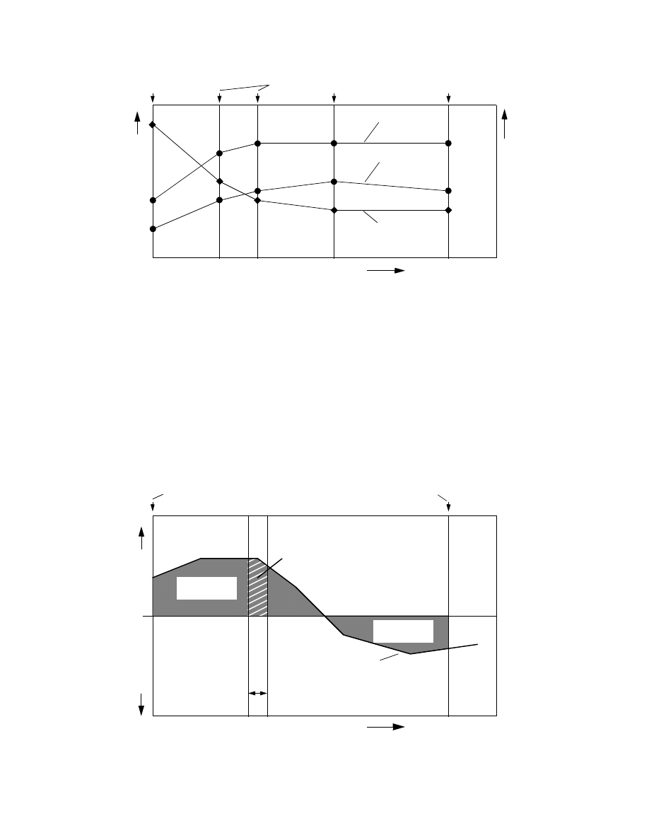
All specified-flow and specified-head cells implemented by FHB1 use the same set of simulation times
to define the function of flow or head (fig. 1). One or more times for specifying flow and head must be
entered, and the initial time must be zero. If only one time is entered, flows or heads will not change during
the simulation. Otherwise, the functions are used for interpolating flow and head at individual time steps.
Note that a specified simulation time can be equal to an immediately preceding simulation time. This allows
a single simulation time to have two values of flow or head at each cell, resulting in the ability to simulate
step-type hydrologic responses in the ground-water model. Other than the initial time, times for specifying
flow and head need not coincide with starting or ending times of time steps or stress periods. The final time
normally coincides with the maximum simulation time; however, FHB1 will interpolate within functions or
extrapolate beyond the ends of functions to compute flow and head for any time step.
Although FHB1 offers the greatest advantages for transient simulations, the package also can be used
in steady-state simulations. Two options are included for computation of values of flow, head, and auxiliary
variables in steady-state simulations. For the first option, FHB1 takes values at the starting point of the
simulation. This option is appropriate for steady-state simulations that will be used as starting conditions for
following transient simulations that use FHB1. For the second option, FHB1 interpolates values in the same
way that values are interpolated in transient simulations. This option allows simulation of steady-state flow
with transient solute transport or other processes.
Specified-Flow Conditions
FHB1 input includes the number of cells at which flows will be specified for the simulation. If a value
of zero is specified, FHB1 will be used for specified-head conditions only. For each specified-flow cell, the
program reads the layer, row, and column indices of the cell, and a flow value for each of the times used to
define the functions. Flow values are specified in units of volume per unit time, using units consistent with
other length and time units used in the simulation.
The values of flow and time define a function for each specified-flow location. The area on a graph
between a function for a model cell and the ordinate axis from the start to the end of the simulation defines
the volumes of flow into and (or) out of the aquifer for the entire simulation (fig. 2). Before each time step,
the program computes area between the ordinate axis and each flow function from the start to the end of the
time step. The resulting areas are the volumes of water entering or leaving the aquifer for the time step.
Volumes are divided by time-step length,
∆
t, to get flow rates at each specified-flow cell for the time step.
Conceptualization of Flow and Head Boundary Package (FHB1)
9
With this procedure, the total volume of flow at each specified-flow cell for a simulation does not vary with
number and length of time steps used in the simulation.
At the start of each time step, FHB1 computes flow for each specified-flow cell. Flow values are stored
in an array and are incorporated on the right-hand side of the finite-difference equation for each
specified-flow cell. The procedure of incorporating specified-flow values in the finite-difference equations
is identical to the procedure used by McDonald and Harbaugh (1988) for the WEL Package. For more infor-
mation on the structure of the finite-difference equations, see McDonald and Harbaugh (1988).
When a solution is reached using an iterative or direct solver, the flow values are used in calculating
volumetric mass balances for the model. Cell-by-cell specified-flow values can be written or recorded in the
same way that flow quantities are written or recorded for other MODFLOW packages.
SIMULATION TIME
FL
O
W
, IN VO
LUM
E
Flow at model
cell A
Flow at model
cell B
Head at model
cell C
Figure 1. An example of definition of functions of flow and head for individual model cells.
Times at which head and flow are specified
HEAD, IN L
E
NG
T
H
PER UNIT T
IME
SIMULATION TIME
Start of simulation
End of simulation
IN
TO
AQ
U
IFE
R
OUT
OF
AQ
UIFE
R
Total volume
into aquifer
Total volume
out of aquifer
Length of time
step
n,
∆
t
n
Volume entering aquifer
during time step
n
FLOW,
I
N
V
O
LUM
E
P
E
R
UNIT
TI
M
E
Specified-flow function
Figure 2. Volume of water entering the aquifer at a specified-flow location during a
time step and during the entire simulation.
10 Documentation of a Computer Program (FHB1) to Simulate Specified-Flow and Specified-Head Boundaries
Specified-Head Conditions
FHB1 input includes the number of specified-head cells active for the simulation. If a value of zero is
specified, FHB1 will be used for specified-flow conditions only. For each specified-head cell, the program
reads the layer, row, and column indices of the cell, and a head value for each of the times used to define
the functions. Head values are specified with a unit of length and a datum that are consistent with other head
values used in the simulation.
Specified-head cells use the “constant-head” feature of the BCF Package in MODFLOW (McDonald
and Harbaugh, 1988) and add the capability of changing head values over time. The incorporation of
specified-head in MODFLOW is similar to that of the CHD Package (Leake and Prudic, 1991). However,
FHB1 allows head variations to be specified independently of starting and ending times of stress periods.
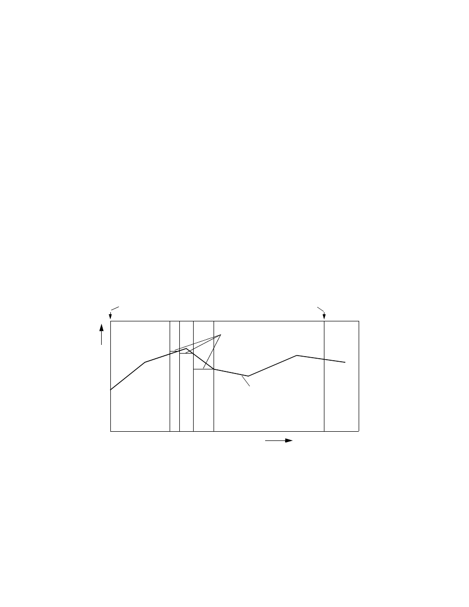
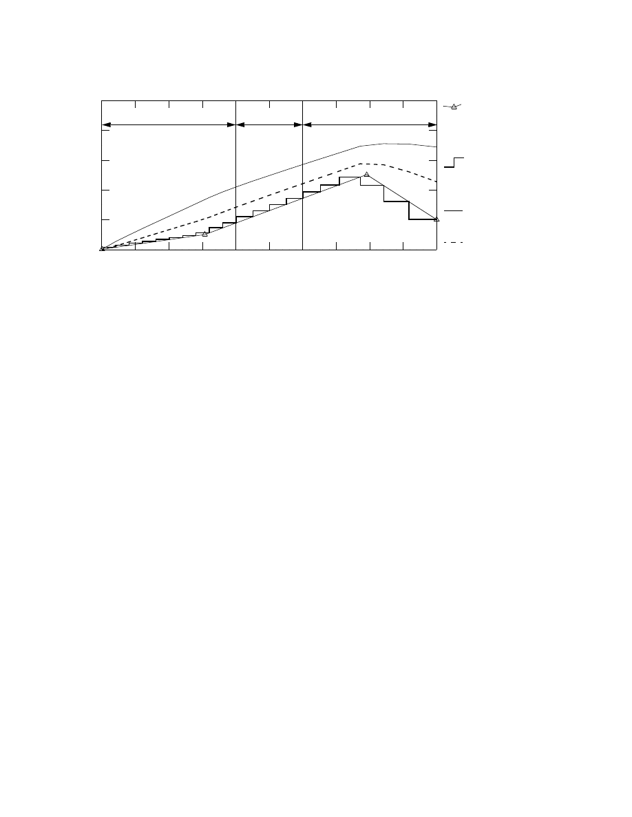
The head values and the times in FHB1 define a function for each specified-head cell (fig. 3). The total
simulation time at the end of a time step is used to interpolate head at each specified-head location. Interpo-
lation at the end of the time step is consistent with the fully implicit finite-difference scheme of MODFLOW
and is the same approach used by the CHD Package (Leake and Prudic, 1991). Note that although times
used to specify variations in head do not need to correspond to starting and ending times of time steps, the
lengths of time steps is an important factor in the detail to which variations in specified head is simulated.
The peak in specified head in time step n in the example (fig. 3) is not simulated because the peak falls in
the middle of a time step. If a certain level of detail is desired in representing the specified-head functions,
users can carry out trial-and-error sensitivity analyses to determine the appropriate lengths for time steps.
At the start of each time step, FHB1 computes head for each specified-head cell. Head values are stored
in MODFLOW arrays that contain the head for the current and previous time steps. Because FHB1 uses the
constant-head feature of the BCF Package, no further operations are needed by FHB1 for formulation of
finite-difference equations and calculation of an overall volumetric budget. Flow volumes and rates to or
from specified-head cells are included in the overall volumetric budget in totals of “constant head” volumes
and rates. Flow rates to individual specified-head cells can be saved or printed using options in the BCF
Package.
SIMULATION TIME
Head for time steps
n-1, n, and n+1
Figure 3. Interpolation of specified-head function for individual time steps.
H
E
A
D
, IN
LEN
G
TH
Ti
me
st
e
p
n
-1
Ti
me
st
e
p
n
Ti
me
st
e
p
n
+1
Start of simulation
End of simulation
Specified-head function
Applicability and Limitations
11
Auxiliary Variables
MODFLOW can make use of boundary flow and head values defined by FHB1; however, other related
programs may require additional variables to be defined for cells at which flow or head are specified. For
example, the particle-tracking program MODPATH (Pollock, 1994) requires specification of an integer
code that indicates which cell face a boundary flow enters or leaves a cell. Also, solute-transport model
MOC3D (Konikow and others, 1996) requires that solute concentration be defined for constant-flow and
constant-head cells. To allow compatibility with MODPATH, MOC3D, and perhaps other programs to be
developed in the future, FHB1 allows definition of an integer auxiliary variable and up to five real auxiliary
variables that are associated with specified-flow and specified-head cells. The auxiliary variables are not
needed in simulations using MODFLOW-96 to solve only the flow equation.
The integer auxiliary variable is required input to the FHB1 Package and is read along with layer, row,
and column indices for each specified-flow and specified-head cell. For simulations using MODFLOW-96
in which the variable is not needed, users may enter zero or any other integer value.
Definition of real auxiliary variables for specified-head and specified-flow cells is optional. The list of
auxiliary variables for specified-flow cells is treated separately from the list of auxiliary variables for
specified-head cells and users may define from zero to five real auxiliary variables for each of the two
groups. For each variable, a character string containing the variable name and a number defining a
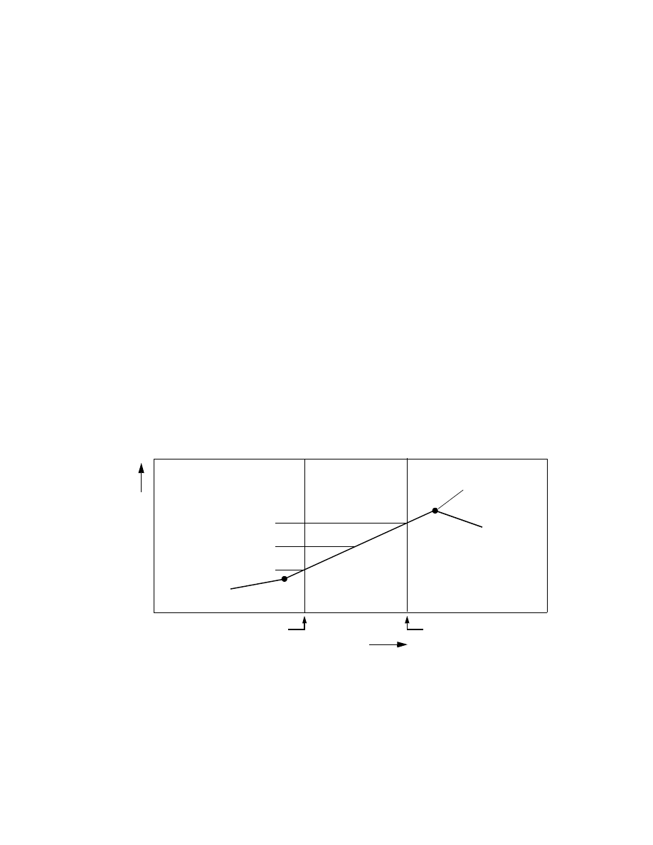
time-weighting factor is read. Values of the variable are read for each of the times used to specify flow and
head for each specified-flow and specified-head cell. With this information, FHB1 interpolates values of
each variable every time step in much the same way that specified head is interpolated. The time-weighting
factor, W, is a number ranging from 0.0 to 1.0 that specifies the relative time within each time step at which
values of a variable will be computed (fig. 4). A value of 0.5 results in the values of a variable being
computed at the center of each time step and a value of 1.0 results in the values of a variable being computed
at the end of each time step. Interpolated values of auxiliary variables for each time step are stored in arrays
that can be accessed by MOC3D or other programs.
APPLICABILITY AND LIMITATIONS
The specified-flow and specified-head features of FHB1 are applicable for simulating known or
estimated inflow or outflow quantities and head variations in ground-water models using MODFLOW.
SIMULATION TIME
Figure 4. Effect of time-weighting factor,
W, on interpolation of value of an auxiliary variable within
a time step.
VA
LU
E
OF AU
X
IL
IAR
Y
Start of time step
Specified value of
VA
RIA
B
L
E
auxiliary variable
End of time step
W=1.0
W=0.5
W=0.0
Value of variable for:

12 Documentation of a Computer Program (FHB1) to Simulate Specified-Flow and Specified-Head Boundaries
Application can be made to simulate effects of features such as wells, streams, and lakes, that cause addition
or removal of water from the system or cause head to vary. The package gives model users the ability to
simulate transient variations in flow and head with model stress periods that may not have been designed
for simulating changes of the boundary flow and head. For example, the package is useful for simulating
features such as water-supply wells pumped at rates that change continually or at times other than starts and
ends of model stress periods. The package also is useful for simulating continual or step changes in head of
surface-water features such as streams, lakes, reservoirs, and gravel pits. The package requires that flow and
head values for all cells implemented by the package be specified using a single set of simulation times.
In addition to physical boundary features, FHB1 can be used to simulate flow quantities and head varia-
tions at ground-water model boundaries that do not coincide with flow-system boundaries. This application
allows boundary-flow rates and head values to be estimated or extracted from another ground-water model
that simulates flow within a larger area. That application is known as “telescopic mesh refinement” (Ward
and others, 1987; Anderson and Woessner, 1992, p. 61) or “embedded-mesh modeling.” This ability to use
fluxes from a larger regional, or subregional, ground-water model is useful in studying relatively small parts
of the larger regional or subregional flow systems. Such applications are common in studies of well fields
and contaminant movement. These small-scale ground-water models seldom can incorporate physical
flow-system boundaries. The ability to efficiently extract boundary fluxes out of a regional model and apply
them to smaller-scale models is important in both reducing the costs and improving the confidence in the
small-scale ground-water models.
Basic assumptions for FHB1 are the same as for other specified-flow and head features in MODFLOW.
Formulation of finite-difference equations for specified-flow cells in FHB1 is the same as formulation for
wells in the WEL Package. Formulation for specified-head cells is carried out by the BCF Package;
therefore, assumptions for specified-head cells are the same as for constant-head cells. For information on
specified-flow and constant-head features in MODFLOW, see McDonald and Harbaugh (1988) and
Harbaugh and McDonald (1996).
An advantage in using FHB1 to simulate specified-flow and specified-head boundaries is that times for
specifying changes in rates of flow and boundary head can be independent of times that model stress periods
and time steps change. Users should note, however, that the lengths and numbers of model time steps will
control the detail in simulating model response to the functions describing specified flow and specified
head. If the specified values of flow and (or) head are changing rapidly during a part of a simulation, then
to simulate the effects of the rapid changes, users must set up the model with sufficiently small time steps
during those periods.
EXAMPLE PROBLEM
The example problem described in this section illustrates the use of FHB1. MODFLOW input data sets
and the output listing file for the problem presented here are given in the appendix. The problem uses a
model grid consisting of 1 layer, 3 rows, and 10 columns (fig. 5). Cell dimensions in the horizontal direc-
tions are 1,000 ft on each side. The ground-water system is homogeneous and isotropic, has a transmissivity
of 5,000 ft
2
/d, and has a storage coefficient of 0.01. The problem simulates transient flow for 1,000 days
using three stress periods. The first stress period is 400 days long and is divided into 10 time steps of equal
length. The second stress period is 200 days long and is divided into four time steps of equal length. The
third stress period is 400 days long and is divided into six time steps with each successive time step 1.1 times
longer than the previous time step. This scheme results in initial and final time-step lengths of 51.8 days and
83.5 days, respectively.
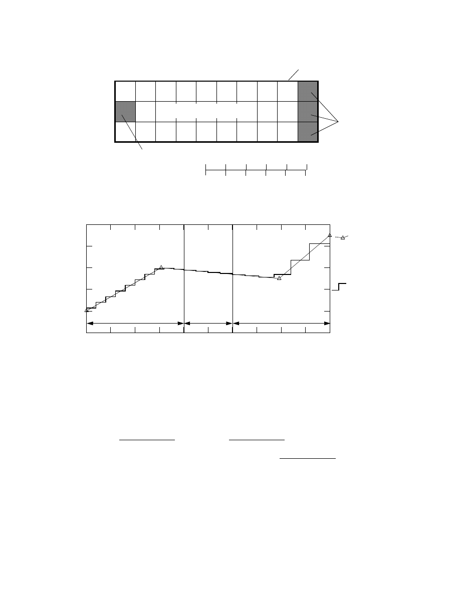
Flow is specified in the FHB1 Package at the cell in column 1 of row 2, and head is specified at all three
cells in column 10. Flow and head are specified at 0, 307, 791, and 1,000 days since start of the simulation
(figs. 6, 7). Of these times, the first two are in the first stress period and the second two are in the third stress
period. The middle two times do not coincide with starting or ending times of stress periods. Note that all
Example Problem
13
specified-flow and specified-head cells must have values defined at these four times. The specified flow
values defined for the four times are 2,000, 6,000, 5,000, and 9,000 ft
3
/d, respectively.
The total volume of inflow for the 1,000-day period, V
t
, can be calculated as the area under the flow
curve from the start to the end of the simulation (fig. 6). The resulting flow is
When using the example, problem the FHB1 Package computed the same volume, 5,353,000 ft
3
, by
summing flow volumes for each of the 20 time steps (see appendix).
Specified head for rows 1–3, column 10, is calculated by FHB1 each time step using values of 0, 1, 5,
and 2 ft, respectively, at simulation times of 0, 307, 791, and 1,000 d (fig. 7). The value for each time step
is interpolated at the time corresponding to the end of the step. Using this procedure, local minimums or
maximums may not be simulated unless the times of minimum or maximum head are the same as ends of
1
2
3
1
2
3
4
5
6
7
8
9
10
MODEL COLUMN
MO
DEL
RO
W
No-flow boundary
Specified-head
cells
Figure 5. Model grid used in example problem.
5,000 FEET
4,000
3,000
2,000
1,000
0
0
300
600
900
1,200 1,500 METERS
Specified-flow cell
Transmissivity—
Storage coefficient—
5,000 ft
2
/d
0.01
SIMULATION TIME, IN DAYS
F
L
O
W
, I
N
CUBIC FEET
PER DAY
Figure 6. Input and calculated specified flow for cell in column 1 of row 2.
10,000
8,000
6,000
4,000
2,000
0
0
100
300
400
500
600
700
800
900
1,000
200
Stress period 1
Stress period 3
Stress period 2
EXPLANATION
Input specified
flow for column 1
Calculated specified
flow for column 1
of row 2. Line
of row 2 during
each time step.
is trend of
interpolation.
V
t
= (307-0) d
×
(6,000+2,000) ft
3
/d
2
+ (791-307) d
×
(6,000+5,000) ft
3
/d
2
+
(1,000-791) d
×
(9,000+5,000) ft
3
/d
2
= 5,353,000 ft
3
.
14 Documentation of a Computer Program (FHB1) to Simulate Specified-Flow and Specified-Head Boundaries
time steps. For example, the maximum specified head of 5 ft occurs at 791 d. This simulation time falls
within a time step that starts at 771.6 d and ends at 840.6 d. A value of 4.84 ft is calculated as the specified
head for this time step using linear interpolation at the simulation time 840.6 d. Smaller time steps would
allow closer approximation of this maximum value.
0
1,000
100
200
300
400
500
600
700
800
900
SIMULATION TIME, IN DAYS
10
0
2
4
6
8
HEAD, IN FEET ABOVE DATUM
EXPLANATION
Computed head in
column 2 of row 2.
Computed head in
column 6 of row 2.
Calculated specified
head for rows 1–3,
column 10, during
each time step.
Input specified head for
rows 1–3, column 10.
Figure 7. Input and calculated specified head in rows 1–3, column 10, and computed head in row 2, columns 2
and 6.
Stress period 1
Stress period 2
Stress period 3
Line is trend of
interpolation.

Implementation of Flow and Head Boundaries in the Ground-Water Model
15
IMPLEMENTATION OF FLOW AND HEAD BOUNDARIES IN THE
GROUND-WATER MODEL
FHB1 is designed for incorporation into the USGS three-dimensional finite-difference modular
ground-water flow model, MODFLOW-96 (Harbaugh and McDonald, 1996). The package is not
compatible with earlier versions of MODFLOW, such as the program documented by McDonald and
Harbaugh (1988).
FHB1 consists of five FORTRAN subroutines (modules)—FHB1AL, FHB1RP, FHB1AD, FHB1FM,
and FHB1BD. The MAIN program of the ground-water flow model must be modified to call these modules.
Call statements to the modules must be placed in sections of the MAIN program in which the particular
procedure is being carried out for other packages. For example, the FHB1AL module must be called within
the section of the MAIN program in which other allocation modules (for example BAS1AL) are called. In
all sections of the MAIN program, the call to the Basic (BAS) Package module (subroutine) must come
before any other module call statements. The authors have selected IUNIT (21) as the package file unit
(McDonald and Harbaugh, 1988, p. 4–9 through 4–12). The package file unit is the FORTRAN unit number
from which input data are read. The call statements to add to the MAIN program are as follows:
Add a new call statement for the FHB1AL module after comment C4 and within the group of statements
that calls BCF5AL, WEL5AL, DRN5AL, and other space-allocation modules:
IF(IUNIT(21).GT.0) CALL FHB1AL(ISUM,LENX,LCFLLC,LCBDTM,LCFLRT,
1 LCBDFV,LCBDHV,LCHDLC,LCSBHD,NBDTIM,NFLW,NHED,IUNIT(21),
2 IOUT,IFHBCB,NFHBX1,NFHBX2,IFHBD3,IFHBD4,IFHBD5,
3 IFHBSS,ISS)
Add a new call statement for the FHB1RP module after comment C6 and within the group of statements
that calls the BAS5RP, BCF5RP, SIP5RP, and SOR5RP:
IF(IUNIT(21).GT.0) CALL FHB1RP(X(LCIBOU),NROW,NCOL,NLAY,
& X(LCFLLC),X(LCBDTM),NBDTIM,X(LCFLRT),NFLW,NHED,
& X(LCHDLC),X(LCSBHD),IUNIT(21),IOUT,
& NFHBX1,NFHBX2,IFHBD3,IFHBD5)
Add a new call statement for the FHB1AD module after the statement that calls the BAS5AD module:
IF(IUNIT(21).GT.0) CALL FHB1AD(X(LCHNEW),X(LCHOLD),NCOL,NROW,NLAY,
& ISS,TOTIM,DELT,X(LCBDTM),NBDTIM,X(LCFLRT),
& X(LCBDFV),X(LCBDHV),NFLW,X(LCSBHD),X(LCHDLC),NHED,
& NFHBX1,NFHBX2,IFHBD3,IFHBD4,IFHBD5,IFHBSS)
Add a new call statement for the FHB1FM module after comment C7C2A and within the group of
statements that call BCF5FM, WEL5FM, DRN5FM, and other formulation modules:
IF(IUNIT(21).GT.0) CALL FHB1FM(X(LCRHS),X(LCIBOU),X(LCFLLC),
1 X(LCBDFV),NFLW,NCOL,NROW,NLAY,IFHBD4)
Add a new call statement for the FHB1BD module after comment C7C4 and within the group of statements
that call BCF5BD, WEL5BD, DRN5BD, and other budget modules:
IF(IUNIT(21).GT.0) CALL FHB1BD(X(LCFLLC),X(LCBDFV),NFLW,
1 VBNM,VBVL,MSUM,X(LCIBOU),DELT,NCOL,NROW,NLAY,KKSTP,KKPER,
2 IFHBCB,ICBCFL,X(LCBUFF),IOUT,IFHBD4)
If desired, another IUNIT element can be used rather than 21. To do this, change all above references to
IUNIT(21) to the new value.

16 Documentation of a Computer Program (FHB1) to Simulate Specified-Flow and Specified-Head Boundaries
INPUT INSTRUCTIONS FOR FLOW AND HEAD BOUNDARY PACKAGE
Input for FHB1 is read from the IUNIT(21), specified in the Basic Package input (McDonald and
Harbaugh, 1988, chap. 4, p. 9–11). All input is free format, which requires each of the numbered data groups
to start on a new input record. More than one record can be used for any data group and numbers within data
groups must be separated by at least one space or a comma. Integer data types cannot include a decimal
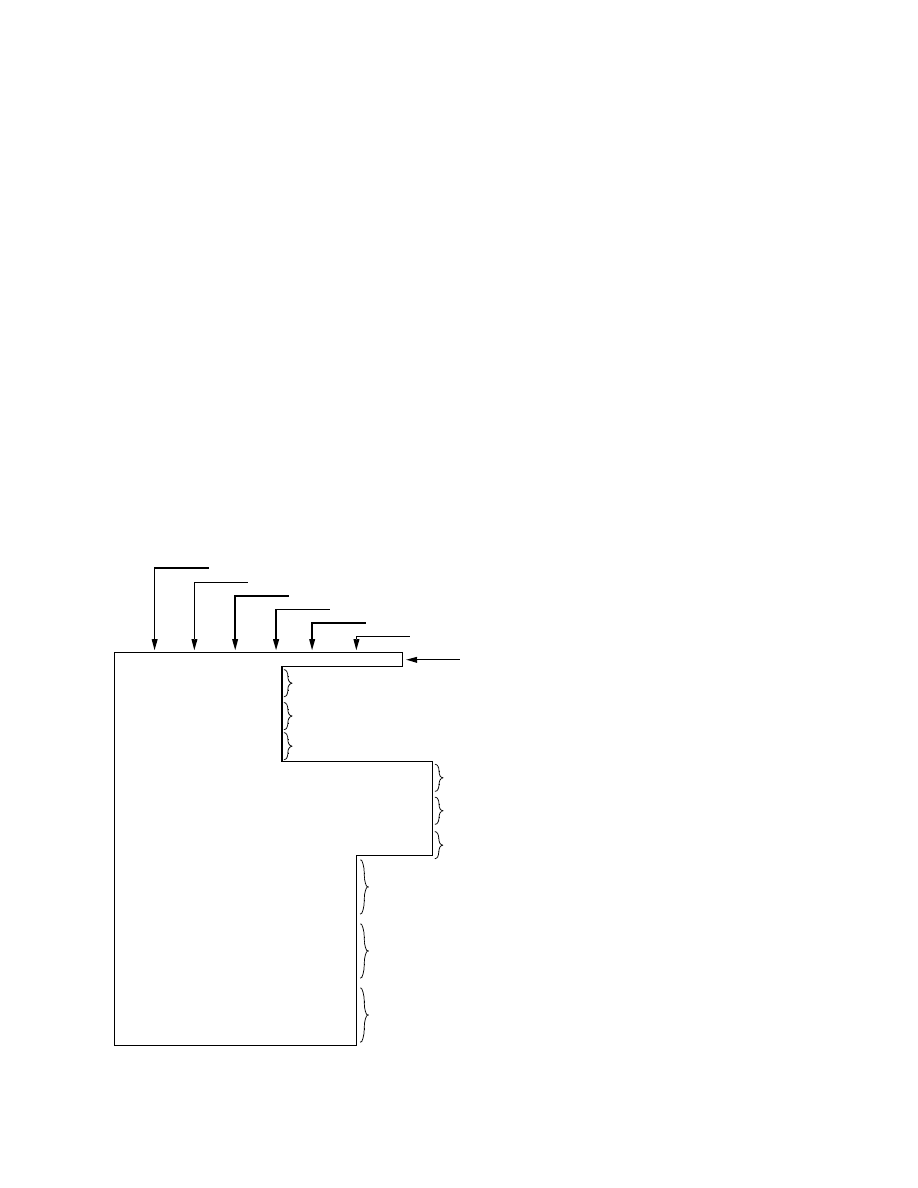
point. Blank spaces are not treated as zeros. For an example annotated input data set, refer to figure 8.
FOR EACH SIMULATION
1. Data:
NBDTIM NFLW
NHED
IFHBSS
IFHBCB
NFHBX1 NFHBX2
Type:
Integer
Integer
Integer
Integer
Integer
Integer
Integer
Omit data item 2 if NFHBX1=0. Input item 2 consists of one record for each of NFHBX1
auxiliary variables.
2. Data:
VarName Weight
Type:
Character Real
Omit data item 3 if NFHBX2=0. Input item 3 consists of one record for each of NFHBX2
auxiliary variables.
3. Data:
VarName Weight
Type:
Character Real
Data items 4a and 4b are required for all simulations. Include NBDTIM times in data item 4b.
4a. Data:
IFHBUN CNSTM
IFHBPT
Type:
Integer
Real
Integer
4b. Data:
BDTIM(NBDTIM)
Type:
Real
Omit data items 5a and 5b if NFLW=0. Input item 5b consists of one set of numbers for each of
NFLW cells. Each set of numbers includes layer, row, and column indices, an integer auxiliary
variable, and NBDTIM values of specified flow.
5a. Data:
IFHBUN CNSTM
IFHBPT
Type:
Integer
Real
Integer
5b. Data:
Layer
Row
Column
IAUX
FLWRAT(NBDTIM)
Type:
Integer
Integer
Integer
Integer
Real
Omit data items 6a and 6b if NFHBX1=0 or if NFLW=0. Include one set of data items 6a and 6b
for each of NFHBX1 auxiliary variables. Input item 6b consists of one set of numbers for each of
NFLW cells. Each set includes NBDTIM values of the variable.
6a. Data:
IFHBUN CNSTM
IFHBPT
Type:
Integer
Real
Integer
6b. Data:
AuxVar(NBDTIM)
Type:
Real
Input Instructions
17
Omit data items 7a and 7b if NHED=0. Input item 7b consists of one set of numbers for each of
NFLW cells. Each set of numbers includes layer, row, and column indices, an integer auxiliary
variable, and NBDTIM values of specified head.
7a. Data:
IFHBUN CNSTM
IFHBPT
Type:
Integer
Real
Integer
7b. Data:
Layer
Row
Column
IAUX
SBHED(NBDTIM)
Type:
Integer
Integer
Integer
Integer
Real
Omit data items 8a and 8b if NFHBX2=0 or if NHED=0. Include one set of data items 8a and 8b
for each of NFHBX2 auxiliary variables. Input item 8b consists of one set of numbers for each of
NHED cells. Each set includes NBDTIM values of the variable.
8a. Data:
IFHBUN CNSTM
IFHBPT
Type:
Integer
Real
Integer
8b. Data:
AuxVar(NBDTIM)
Type:
Real
4 1 3 0 44 2 2
CONCENTRATION 0.5
TEMPERATURE 1.0
CONCENTRATION-hd 0.5
TEMPERATURE-hd 1.0
31 1. 1
0.0 307. 791. 1000.
31 1. 1
1 2 1 0 2000. 6000. 5000. 9000.
31 1. 1
.01 .00333 .004 .00222
31 1. 1
13. 15. 15. 15.5
31 1. 1
1 1 10 0 0. 1. 5. 2.
1 2 10 0 0. 1. 5. 2.
1 3 10 0 0. 1. 5. 2.
31 1. 1
.01 .01 .01 .01
.01 .01 .01 .01
.01 .01 .01 .01
31 1. 1
15. 15. 15. 15.
15. 15. 15. 15.
15. 15. 15. 15.
Data item 2—Auxiliary-variable names and weighting factors for specified-flow cell.
Data item 3—Auxiliary-variable names and weighting factors for specified-head cells.
Data Item 4—Header record and four times at which flow, head, and auxiliary-variable
NBDTIM—Flow, head, and values of auxiliary variables will be specified at four times.
NFLW—Simulation will have one specified-flow cell.
IFHBSS—For steady-state, use flow, head, and auxiliary variables at time=0.
IFHBCB—Cell-by-cell flow terms will be recorded on unit 44.
NFHBX1—Flow cells will include two auxiliary variables.
NFHBX2— Head cells will include two auxiliary variables.
Concentration will be computed at center and temperature at end of each time step.
Concentration will be computed at center and temperature at end of each time step.
values will be specified.
Data Item 5—Header record; layer, row, column locations,
IAUX, and four flow values at the specified-flow cell.
Data Item 6—Header record and four values of
source-fluid concentration at the specified-flow cell.
Data Item 6—Header record and four values of
source-fluid temperature at the specified-flow cell.
Data Item 7—Header record; layer, row, column locations, IAUX,
and four head values at the three specified-head cells.
Data Item 8—Header record and four values of source-fluid
concentration at the three specified-head cells.
Data Item 8—Header record and four values of
temperature at the three specified-head cells.
.
NHED—Simulation will have three specified-head cells.
Figure 8. Annotated example input data set for FHB1. Input data are enclosed in border.
Table 1. Primary modules of MODFLOW organized by procedure and package
[Modified from McDonald and Harbaugh (1988, fig. 15)]

18 Documentation of a Computer Program (FHB1) to Simulate Specified-Flow and Specified-Head Boundaries
Explanation of Fields Used in Input Instructions
NBDTIM
is the number of times at which flow and head will be specified for all selected cells.
If NBDTIM = 1,
specified flow and head values will remain constant for the entire
simulation.
If NBDTIM > 1,
specified flow and head values will be computed for each time step using
linear interpolation.
NFLW
is the number of cells at which flows will be specified.
NHED
is the number of cells at which head will be specified.
IFHBSS
is the FHB steady-state option flag. If the simulation is transient, the flag is read but not used.
For steady-state simulations, the flag controls how specified-flow, specified-head, and
auxiliary-variable values will be computed for each steady-state solution.
If IFHBSS = 0,
values of flow, head, and auxiliary variables will be taken at the starting
time of the simulation. This results in use of the first value in arrays
FLWRAT, SBHED, and AuxVar for each respective boundary cell.
If IFHBCB
≠
0,
values of flow, head, and auxiliary variables will be interpolated in the
same way that values are computed for transient simulations.
IFHBCB
is a flag and unit number.
If IFHBCB > 0,
it is the unit number on which cell-by-cell flow terms will be recorded
whenever ICBCFL is set (see McDonald and Harbaugh, 1988, chap. 4,
p. 14–15).
If IFHBCB
≤
0,
cell-by-cell flow terms will not be recorded.
NFHBX1
is the number of auxiliary variables whose values will be computed for each time step for each
specified-flow cell.
NFHBX2
is the number of auxiliary variables whose values will be computed for each time step for each
specified-head cell.
VarName
is the name of an auxiliary variable. Name can include up to 16 characters with no embedded
blank characters.
Weight
is the time-weighting factor for an auxiliary variable specifying the fraction of each time step
at which the value of the variable will be interpolated. Value must be in the range from 0.0 to
1.0.
IFHBUN
is the unit number on which data lists will be read. The same or different unit numbers can be
used to read lists in data items 4b, 5b, 6b, 7b, and 8b.
CNSTM
is a constant multiplier for data list BDTIM (data item 4b), FLWRAT (part of data item 5b),
SBHED (part of data item 7b), and auxiliary variables in data items 6b and 8b.

Input Instructions
19
IFHBPT
is a flag for printing values of data lists in items 4b, 5b, 6b, 7b, and 8b.
If IFHBPT > 0
data list read at the beginning of the simulation will be printed.
If IFHBCB < 0
data list read at the beginning of the simulation will not be printed.
BDTIM
is simulation time at which values of specified flow and (or) values of specified head will be
read. NBDTIM values are required.
Layer
is the layer index of specified-flow cell (data item 5b) or specified-head cell (data item 7b).
Row
is the row index of specified-flow cell (data item 5b) or specified-head cell (data item 7b).
Column
is the column index of specified-flow cell (data item 5b) or specified-head cell (data item 7b).
IAUX
Is an integer auxiliary variable associated with each specified-flow and specified-head
boundary cell. A value is read but not used in simulations of ground-water flow with
MODFLOW-96. IAUX can be used by programs such as MODPATH (Pollock, 1994) to store
information such as the cell face associated with the specified-flow or specified-head boundary.
FLWRAT is volumetric rate of flow at specified-flow cells. A list of NBDTIM values must be specified
for each of NFLW specified-flow cells.
AuxVar
is value of real auxiliary variable at specified-flow and specified-head cells. A list of NBDTIM
values must be specified for each of NFLW specified-flow cells and for each of NHED
specified-head cells.
SBHED
is an array containing NBDTIM values of the head for each specified-head cell.

20 Documentation of a Computer Program (FHB1) to Simulate Specified-Flow and Specified-Head Boundaries
PROGRAM OUTPUT
Output from FHB1 consists of printed output and information recorded to a disk or another storage
device. Printed output can include any arrays read by FHB1. Furthermore, computed rates for each
specified-flow cell can be printed if the rates are not being recorded to a disk or another storage device.
The printed output also includes rates and volumes of flow to or from specified-flow cells in the overall
volumetric budget. The budget is printed by MODFLOW and includes flow rates and volumes for all
flow-component and stress packages used in a simulation. The left side of the budget lists cumulative
volumes of inflow and outflow for the entire simulation. The right side of the budget lists rates of inflow
and outflow for the most recent time step. Components in the volumetric budget generated by FHB1 are
denoted with the label “SPECIFIED FLOWS.” If a value greater than zero is specified for IFHBCB, FHB1
will record cell-by-cell flow terms for time steps in which a nonzero value of ICBCFL is specified
(McDonald and Harbaugh, 1988, chap. 4, p. 14–15). The cell-by-cell flow terms are recorded in an unfor-
matted file with one element for each cell in the model grid or in an unformatted file with a list containing
layer, row, and column indices and computed flow for each specified-flow cell. A value of zero is recorded
for cells that are not specified-flow cells. The sign convention is that positive quantities denote flow into the
ground-water system and negative quantities denote flow out of the ground-water system. The header record
for the unformatted arrays includes the label “SPECIFIED FLOWS.” MODFLOW computes, prints, and
records flow components to or from “constant-head” cells. Specified-head cells in FHB1 are treated as
constant-head cells in MODFLOW budget calculations.
MODULE DOCUMENTATION
FHB1 contains five modules (subroutines), each of which is called by the main program of
MODFLOW. Required changes to the main program are given in the section of this report titled
“Implementation of Flow and Head Boundaries in the Ground-Water Model” (p. 9). The modules in FHB1
are
FHB1AL Reads number of times at which flow and head will be specified, number of specified-flow
and specified-head cells, flag for steady-state option, flag for cell-by-cell flow terms,
numbers of auxiliary variables, and names and weights of auxiliary variables; allocates
space for data arrays.
FHB1RP
Reads data arrays containing times at which flow and head will be specified, locations and
rates for specified-flow cells, locations and heads for specified-head cells, and values of
auxiliary variables; if requested, prints array values.
FHB1AD Computes specified-flow, specified-head, and auxiliary-variable values for the current time
step.
FHB1FM Subtracts specified-flow values from the right-hand-side array (RHS).
FHB1BD Incorporates specified-flow rates into the overall mass balance and writes cell-by-cell flow
rates if option is selected.
The last two characters in the names of each of the modules are an abbreviation for the procedure that
the module carries out. Most flow-component and stress packages in MODFLOW use four procedures—
Allocate (AL), Read and Prepare (RP), Formulate (FM), and Budget (BD) (table 1). In addition to these
basic procedures, FHB1 uses the Advance procedure (AD) to calculate the specified flows and heads at each
time step.

FHB1AL
21
FHB1AL
Narrative for Module FHB1AL
This module reads number of times at which flow and head will be specified, number of specified-flow
and specified-head cells, flag for steady-state option, flag for cell-by-cell flow terms, numbers of auxiliary
variables, and names and weights of auxiliary variables; and allocates space for data arrays in the X array
(McDonald and Harbaugh, 1988, chap. 3, p. 22–23). Operations are carried out in the following order:
Print a message identifying the package.
1. Read number of times at which flow and head will be specified, NBDTIM; number of specified-flow
cells, NFLW; number of specified-head cells, NHED; steady-state option flag, IFHBSS; unit number
for cell-by-cell flow terms, IFHBCB; number of auxiliary variables for specified-flow cells,
IFHBX1; and number of auxiliary variables for specified-head cells, IFHBX2.
2. Print number of times at which flow and head will be specified. Stop if no times are specified.
3. Print number of specified-flow cells and number of specified-head cells.
4. If cell-by-cell flow terms are to be saved, print unit number.
5. Read names and time-weighting factors for auxiliary variables.
6. Allocate storage for the following arrays:
BDTIM
individual times at which values of specified flow and specified head read by package
will be applied,
IFLLOC
layer, row, and column location, and integer auxiliary variable for each of NFLW
specified-flow cells,
FLWRAT specified-flow rates for each of NFLW specified-flow cells for each of NBDTIM
simulation times,
Define (DF)
Allocate (AL)
Read and prepare (RP)
Stress (ST)
Read and prepare (RP)
Advance (AD)
Formulate (FM)
Approximate (AP)
Output Control (OC)
Budget (BD)
Output (OT)
BAS1
BCF1
WEL1
RCH1
RIV1
DRN1
EVT1
GHB1
SIP1
SOR1
FHB1
BAS1DF
BAS1AL
BAS1RP
BAS1ST
BAS1AD
BAS1FM
BAS1OC
BAS1OT
FHB1AL
FHB1RP
FHB1AD
FHB1FM
FHB1BD
BCF1AL
BCF1RP
BCF1FM
BCF1BD
WEL1AL
WEL1RP
WEL1FM
WEL1BD
RCH1AL
RCH1RP
RCH1FM
RCH1BD
RIV1AL
RIV1RP
RIV1FM
RIV1BD
DRN1AL
DRN1RP
DRN1FM
DRN1BD
EVT1AL
EVT1RP
EVT1FM
EVT1BD
GHB1AL
GHB1RP
GHB1FM
GHB1BD
SIP1AL
SIP1RP
SIP1AP
SOR1AL
SOR1RP
SOR1AP
Packages
Procedure

22 Documentation of a Computer Program (FHB1) to Simulate Specified-Flow and Specified-Head Boundaries
BDFV
computed values of specified-flow cell variables for the current time step, including flow
and values of auxiliary variables.
IHDLOC
layer, row, and column location, and integer auxiliary variable for each of NHED
specified-head cells,
SBHED
specified-head values for each of NHED specified-head cells for each of NBDTIM
simulation times,
BDHV
computed values of specified-head cell auxiliary variables for the current time step.
7. Calculate and print the amount of space used by FHB1.
8. If space in the X array is not sufficient, print a warning message.
9. RETURN.
FHB1AL
23
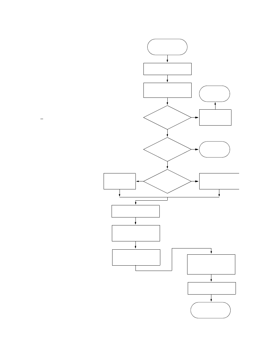
Flowchart for Module FHB1AL
Print a message
identifying this package
1
Read values of NBDTIM
NFLW, NHED, and
IFHBCB
2
Print NFLW, NHED, and
If cell-by-cell terms are
RETURN
4
5
ENTER FHB1AL
10
NBDTIM is the number of times
used to define functions of
flow and head.
NFLW is the number of specified-
flow cells.
NHED is the number of specified-
head cells.
IFHBCB is a flag and a unit
number:
> 0, unit number on which
cell-by-cell flow terms will
be recorded whenever
ICBCFL is set.
< 0, cell-by-cell flow terms
will not be printed.
BDTIM is array of times at which
values of specified flow and
specified head will be read.
IFLLOC is array with layer, row,
and column location, and
integer auxiliary variable for
each of NFLW specified-flow
cells.
FLWRAT is array with specified-
flow rates for each of NFLW
specified-flow cells for each
of NBDTIM simulation times.
BDFV is array with computed
values of specified-flow cell
variables for the current time
step, including flow and
values of auxiliary variables.
IHDLOC is array with layer, row,
and column location, and
integer auxiliary variable for
each of NHED specified-head
cells.
SBHED is array with specified-
head values for each of NHED
specified-head cells for each
of NBDTIM simulation times.
BDHV is array with computed
values of specified-head cell
auxiliary variables for the
current time step.
NFLW < 1 and
NHED < 1
Yes
No
?
RETURN
Cancel FHB1
STOP
option
NBDTIM < 1
Yes
No
?
NBDTIM = 1
Yes
No
?
Print message that
flow and head will
remain constant
Print value
of NBDTIM
Print space used
8,9
to be saved, print unit
number
Allocate space for arrays
7
BDTIM, IFLLOC, BDFV,
IHDLOC, SBHED,
and BDHV
Read names and
time-weighting factors
of auxiliary variables
6
steady-state option flag

24 Documentation of a Computer Program (FHB1) to Simulate Specified-Flow and Specified-Head Boundaries
Program Listing for Module FHB1AL
SUBROUTINE FHB1AL(ISUM,LENX,LCFLLC,LCBDTM,LCFLRT,LCBDFV,LCBDHV,
& LCHDLC,LCSBHD,NBDTIM,NFLW,NHED,IN,IOUT,IFHBCB,
& NFHBX1,NFHBX2,IFHBD3,IFHBD4,IFHBD5,IFHBSS,ISS)
C
C-----VERSION 0000 10JAN1997 FHB1AL
C ******************************************************************
C ALLOCATE ARRAY STORAGE FOR FLOW AND HEAD BOUNDARY PACKAGE
C ******************************************************************
C
C SPECIFICATIONS:
C ------------------------------------------------------------------
COMMON /FHBCOM/ FHBXNM(10),FHBXWT(10)
CHARACTER*16 FHBXNM
CHARACTER*80 LINE
C ------------------------------------------------------------------
C
C1------IDENTIFY PACKAGE
WRITE(IOUT,1)IN
1 FORMAT(1H0,’FHB1 -- SPECIFIED FLOW PACKAGE, VERSION 1,12/3/96’,
&’ INPUT READ FROM’,I3)
C
C2------READ NUMBER OF TIMES, NUMBER OF SPECIFIED-FLOW CELLS AND
C2------UNIT OR FLAG FOR CELL-BY-CELL FLOW TERMS, NUMBER OF
C2------AUXILIARY VARIABLES.
READ(IN,*) NBDTIM,NFLW,NHED,IFHBSS,IFHBCB,NFHBX1,NFHBX2
C
C3------PRINT NBDTIM, STOP IF NO TIMES ARE TO BE SPECIFIED
IF(NFLW.LT.1.AND.NHED.LT.1) THEN
WRITE(IOUT,4)
4 FORMAT(1X,’SPECIFIED FLOW AND HEAD BOUNDARY OPTION ‘,
& ‘CANCELLED.’,/,1X,’NO BOUNDARY CELLS WERE SPECIFIED.’)
IN=0
RETURN
ENDIF
IF(NBDTIM.LT.1) THEN
WRITE(IOUT,6)
6 FORMAT(1X, ‘SIMULATION ABORTING. NOT ENOUGH TIMES ‘,
& ‘SPECIFIED FOR FHB1 PACKAGE.’)
STOP
ELSE IF(NBDTIM.EQ.1) THEN
WRITE(IOUT,8)
8 FORMAT(1X,’ SPECIFIED FLOW AND HEAD VALUES WILL REMAIN ‘,
& ‘CONSTANT FOR ENTIRE SIMULATION.’)
ELSE
WRITE(IOUT,10) NBDTIM
10 FORMAT(1H ,’TOTAL OF’,I5,’ TIMES WILL BE USED TO DEFINE ‘,
& ‘VARIATIONS IN FLOW AND HEAD.’)
ENDIF
C
C4------PRINT NFLW AND NHED AND STEADY-STATE OPTION
WRITE(IOUT,12) NFLW
12 FORMAT(1H ,’FLOW WILL BE SPECIFIED AT A TOTAL OF’,I5,’ CELLS.’)
WRITE(IOUT,14) NHED

FHB1AL
25
14 FORMAT(1H ,’HEAD WILL BE SPECIFIED AT A TOTAL OF’,I5,’ CELLS.’)
IF(ISS.EQ.0) THEN
WRITE(IOUT,15)
15 FORMAT(1H ,’FHB STEADY-STATE OPTION FLAG WILL BE IGNORED,’/,
& 1H ,’SIMULATION IS TRANSIENT.’)
ELSE
IF(IFHBSS.EQ.0) THEN
WRITE(IOUT,16)
16 FORMAT(1H ,’FLOW, HEAD, AND AUX VARIABLES AT TIME=0 WILL BE ‘,
& /,1H ,’USED IN STEADY-STATE SIMULATIONS.’)
ELSE
WRITE(IOUT,18)
18 FORMAT(1H ,’FLOW, HEAD, AND AUX VARIABLES WILL BE ‘,
& ‘INTERPOLATED’,/,1H ,’IN STEADY-STATE SIMULATIONS.’)
ENDIF
ENDIF
C
C5------IF CELL-BY-CELL FLOW TERMS ARE TO BE SAVED THEN PRINT UNIT #
IF(IFHBCB.GT.0) WRITE(IOUT,20) IFHBCB
20 FORMAT(1X,’CELL-BY-CELL FLOWS WILL BE RECORDED ON UNIT’,I3)
IF(IFHBCB.LT.0) WRITE(IOUT,24)
24 FORMAT(1X,’CELL-BY-CELL FLOWS WILL BE PRINTED WHEN ICBCFL NOT 0’)
C
C6------READ AUXILIARY VARIABLES
IF(NFHBX1.GT.5.OR.NFHBX2.GT.5) THEN
WRITE(IOUT,*) ‘ ABORTING. A MAXIMUM OF 5 AUXILIARY VARIABLES’,
& ‘ CAN BE DEFINED BY FHB.’
STOP
ENDIF
WRITE(IOUT,26) NFHBX1
26 FORMAT(1X,I2,’ AUXILIARY VARIABLES FOR SPECIFIED-FLOW CELLS WILL’,
& /,’ BE DEFINED BY FHB FOR USE BY OTHER PACKAGES.’)
IF(NFHBX1.LT.1) GO TO 38
WRITE(IOUT,28)
28 FORMAT(‘ NAME WEIGHTING FACTOR’,/,1X,32(‘-’))
DO 30 NX=1,NFHBX1
READ(IN,’(A)’) LINE
LLOC=1
CALL URWORD(LINE,LLOC,ISTART,ISTOP,1,N,R,IOUT,IN)
FHBXNM(NX)=LINE(ISTART:ISTOP)
CALL URWORD(LINE,LLOC,ISTART,ISTOP,3,N,FHBXWT(NX),IOUT,IN)
WRITE(IOUT,29) FHBXNM(NX),FHBXWT(NX)
29 FORMAT(1X,A16,F11.2)
IF(FHBXWT(NX).LT.0.0.OR.FHBXWT(NX).GT.1.0) THEN
WRITE(IOUT,*) ‘ Aborting. Weights for Auxiliary variables cannot’
WRITE(IOUT,*) ‘ be less than 0.0 or greater than 1.0.’
STOP
ENDIF
30 CONTINUE
38 WRITE(IOUT,126) NFHBX2
126 FORMAT(1X,I2,’ AUXILIARY VARIABLES FOR SPECIFIED-HEAD CELLS WILL’,
& /,’ BE DEFINED BY FHB FOR USE BY OTHER PACKAGES.’)
IF(NFHBX2.LT.1) GO TO 200
WRITE(IOUT,28)
DO 130 NX=1,NFHBX2

26 Documentation of a Computer Program (FHB1) to Simulate Specified-Flow and Specified-Head Boundaries
READ(IN,’(A)’) LINE
LLOC=1
CALL URWORD(LINE,LLOC,ISTART,ISTOP,1,N,R,IOUT,IN)
FHBXNM(5+NX)=LINE(ISTART:ISTOP)
CALL URWORD(LINE,LLOC,ISTART,ISTOP,3,N,FHBXWT(5+NX),IOUT,IN)
WRITE(IOUT,129) FHBXNM(5+NX),FHBXWT(5+NX)
129 FORMAT(1X,A16,F11.2)
IF(FHBXWT(5+NX).LT.0.0.OR.FHBXWT(5+NX).GT.1.0) THEN
WRITE(IOUT,*) ‘ Aborting. Weights for Auxiliary variables cannot’
WRITE(IOUT,*) ‘ be less than 0.0 or greater than 1.0.’
STOP
ENDIF
130 CONTINUE
C7------ALLOCATE SPACE FOR ARRAYS BDTIM, IFLLOC, FLWRAT, BDFV,
C7------IHDLOC, SBHED, AND BDHV
200 IFHBD3=NBDTIM*(1+NFHBX1)
IFHBD4=2+NFHBX1
IFHBD5=NBDTIM*(1+NFHBX2)
LCBDTM=ISUM
ISUM=ISUM+NBDTIM
LCFLLC=ISUM
ISUM=ISUM+NFLW*4
LCFLRT=ISUM
ISUM=ISUM+NFLW*IFHBD3
LCBDFV=ISUM
ISUM=ISUM+NFLW*IFHBD4
LCHDLC=ISUM
ISUM=ISUM+NHED*4
LCSBHD=ISUM
ISUM=ISUM+NHED*IFHBD5
LCBDHV=ISUM
ISUM=ISUM+NHED*NFHBX2
ISP=ISUM-LCBDTM
C
C8------PRINT NUMBER OF SPACES IN X ARRAY USED BY FLOW PACKAGE.
WRITE(IOUT,210) ISP
210 FORMAT(1X,I8,’ ELEMENTS IN X ARRAY ARE USED BY FHB1’)
ISUM1=ISUM-1
WRITE(IOUT,220) ISUM1,LENX
220 FORMAT(1X,I8,’ ELEMENTS OF X ARRAY USED OUT OF’,I8)
C
C9------IF THERE ISN’T ENOUGH SPACE IN THE X ARRAY THEN PRINT
C9------A WARNING MESSAGE.
IF(ISUM1.GT.LENX) WRITE(IOUT,230)
230 FORMAT(1X,’ ***X ARRAY MUST BE DIMENSIONED LARGER***’)
C10-----RETURN
RETURN
END

FHB1AL
27
List of Variables for Module FHB1AL
Variable
Range
Definition
FHBXNM
Package CHARACTER*16(10), Names of auxiliary variables.
FHBXWT
Package DIMENSION(10), Time-weighting factor for auxiliary variables.
IFHBCB
Package Flag and a unit number:
> 0
Unit number on which cell-by-cell flow terms will be recorded whenever
ICBCFL is set.
= 0
Cell-by-cell flow terms will not be recorded or printed.
< 0
Cell-by-cell flow terms will be printed whenever ICBCFL is set.
IFHBD3
Package Dimension for storing specified-flow values and auxiliary-variable values
associated with specified-flow cells.
IFHBD4
Package Dimension for interpolated specified-flow values and interpolated auxiliary-
variable values associated with specified-flow cells.
IFHBD5
Package Dimension for storing auxiliary-variable values associated with specified-head
cells.
IFHBSS
Package Option flag for steady-state simulations:
= 0
Take flow, head, and auxiliary-variable values at starting time.
≠
0
Interpolate flow, head, and auxiliary-variable values.
IN
Package Primary unit number from which input from this package will be read.
IOUT
Global
Primary unit number for all printed output.
ISP
Module
Number of elements in the X array allocated by this package.
ISS
Global
Flag:
= 0, simulation is transient.
≠
0, simulation is steady state.
ISTART
Module
Index pointing to the start of a word found by module URWORD.
ISTOP
Module
Index pointing to the end of a word found by module URWORD.
ISUM
Global
Element number of the lowest element in the X array that has not yet been
allocated. When space is allocated in the X array, the size of the allocation is added
to ISUM.
ISUM1
Module
ISUM-1.
LCBDFV
Package Location in the X array of the first element of array BDFV.
LCBDHV
Package Location in the X array of the first element of array BDHV.
LCBDTM
Package Location in the X array of the first element of array BDTIM.
LCFLLC
Package Location in the X array of the first element of array IFLLOC.
LCFLRT
Package Location in the X array of the first element of array FLWRAT.
LCHDLC
Package Location in the X array of the first element of array IHDLOC.
LCSBHD
Package Location in the X array of the first element of array SBHED.
LENX
Global
Number of elements in the X array. Value should always equal the dimension of
the X array specified in the MAIN program.
LINE
Module
CHARACTER*80, contents of a record THAT HAS BEEN READ FROM THE
PAGKAGE INPUT FILE. LINE is parsed by URWORD.
LLOC
Module
Index that tells URWORD where to start looking for a word within LINE.
N
Module
Argument place holder for calls to URWORD in which the argument is unused.
NBDTIM
Package Number of times used to define functions of flow and head.
NFHBX1
Package Number of auxiliary variables associated with specified-flow cells.
NFHBX2
Package Number of auxiliary variables associated with specified-head cells.
NFLW
Package Number of specified-flow cells.
NHED
Package Number of specified-head cells.
NX
Module
Index for auxiliary variables.
R
Module
Argument place holder for calls to URWORD in which the argument is unused.

28 Documentation of a Computer Program (FHB1) to Simulate Specified-Flow and Specified-Head Boundaries
FHB1RP
Narrative for Module FHB1RP
This module reads arrays with times at which flow and head will be specified, specified-flow rates,
specified-head values, and auxiliary-variable values. All information is read at the start of the simulation.
Operations are carried out in the following order:
1. Read times at which flow and head values will be specified.
2. If desired, print table of times.
3. Check time values to make sure that first time is zero and that no time is less than the previous time.
Stop if these conditions are not met. To allow for step increases in flow or head, two adjacent time
values can be the same.
4. Read cell indices, integer auxiliary-variable values, and flow rates for all specified-flow cells. If
desired, print table of specified-flow cell indices (layer, row, and column) and flow rates for each
time.
5. Read values of auxiliary variables for specified-flow cells. If desired, print table of values of auxiliary
variables for each time.
6. Read cell indices, integer auxiliary-variable values, and head values for all specified-head cells.
7. At specified-head cell locations, set IBOUND to a negative number. Ignore specified-head conditions
at cells where IBOUND is zero.
8. If desired, print table of specified-head cell indices (layer, row, and column), integer
auxiliary-variable values, and head values for each time.
9. Read values of auxiliary variables for specified-head cells. If desired, print table of values of auxiliary
variables for each time.
10. RETURN.
FHB1RP
29
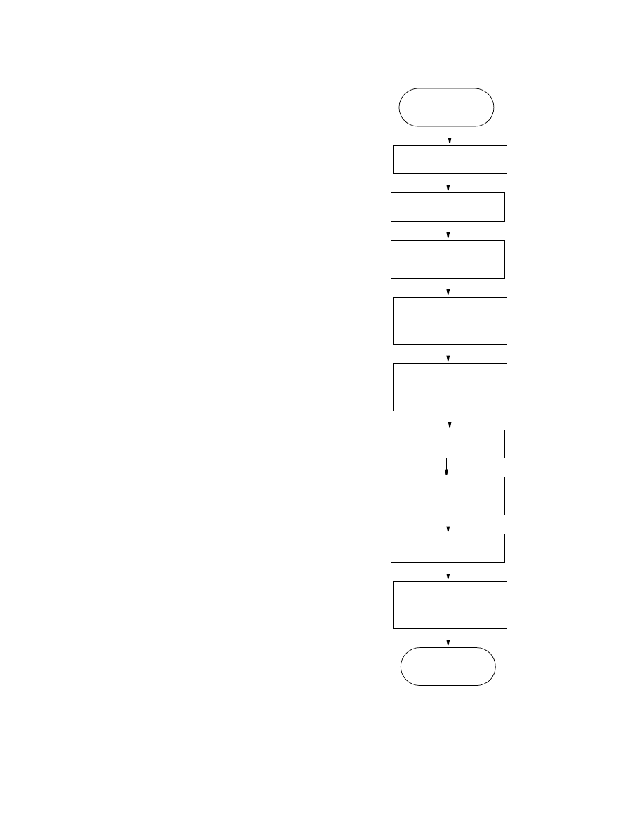
Flowchart for Module FHB1RP
Read BDTIM
1
RETURN
ENTER FHB1RP
10
Make sure that first
3
BDTIM is an array containing individual
times at which values of specified flow
and specified head read by package
will be applied.
IFLLOC is an array containing layer, row,
column location, and integer auxiliary
variable for each of NFLW specified-
flow cells.
FLWRAT is an array containing
specified-flow rates for each of NFLW
specified-flow cells for each of
NBDTIM simulation times.
IHDLOC is an array containing layer, row,
column location, and integer auxiliary
variable for each of NHED specified-
head cells.
SBHED is an array containing specified-
head values for each of NHED
specified-head cells for each of
NBDTIM simulation times.
IBOUND is an array containing the status
of each cell:
< 0, cell is constant-head.
= 0, cell is no-flow.
> 0, cell is variable-head.
time is zero and that
If desired, print table
2
of times
times increase
Read IFLLOC and
4
FLWRAT. If desired,
Read values of auxiliary
5
Read IHDLOC and
6
SBHED
Set IBOUND to negative 7
number at location of
If desired, print table
8
of locations and heads
specified-head cells
print table of locations
and rates
variables for specified-
flow cells. If desired,
print table
Read values of auxiliary
9
variables for specified-
head cells. If desired,
print table

30 Documentation of a Computer Program (FHB1) to Simulate Specified-Flow and Specified-Head Boundaries
Program Listing for Module FHB1RP
SUBROUTINE FHB1RP(IBOUND,NROW,NCOL,NLAY,IFLLOC,BDTIM,NBDTIM,
& FLWRAT,NFLW,NHED,IHDLOC,SBHED,IN,IOUT,
& NFHBX1,NFHBX2,IFHBD3,IFHBD5)
C
C
C-----VERSION 0000 10JAN1997 FHB1RP
C ******************************************************************
C READ TIMES, CELL LOCATIONS, RATES, AND HEADS FOR FLOW AND HEAD
C BOUNDARY PACKAGE
C ******************************************************************
C
C SPECIFICATIONS:
C ------------------------------------------------------------------
COMMON /FHBCOM/ FHBXNM(10),FHBXWT(10)
CHARACTER*16 FHBXNM
CHARACTER*1 DSH1
DIMENSION IBOUND(NCOL,NROW,NLAY),BDTIM(NBDTIM),IFLLOC(4,NFLW),
& FLWRAT(IFHBD3,NFLW),IHDLOC(4,NHED), SBHED(IFHBD5,NHED)
DATA DSH1/’-’/
C ------------------------------------------------------------------
C
C1------READ TIMES AT WHICH SPECIFIED FLOW AND HEAD VALUES WILL BE READ
READ(IN,*) IFHBUN,CNSTM,IFHBPT
WRITE(IOUT,10) IFHBUN,CNSTM
10 FORMAT(1X,’TIMES FOR SPECIFIED-FLOW AND HEAD VALUES WILL BE READ’,
& ‘ ON UNIT’,I4,’ AND’,/,
&’ MULTIPLIED BY’,G12.4,’.’)
READ(IFHBUN,*) (BDTIM(L),L=1,NBDTIM)
DO 12 L=1,NBDTIM
BDTIM(L)=BDTIM(L)*CNSTM
12 CONTINUE
C
C2------IF DESIRED, PRINT TABLE OF TIMES
IF(IFHBPT.GT.0) THEN
WRITE(IOUT,20) NBDTIM
20 FORMAT(1X,I5,’ TIMES FOR SPECIFYING FLOWS AND HEADS:’)
WRITE(IOUT,22) (L,L=1,NBDTIM)
22 FORMAT(16X,I8,4I12)
ND=MIN0(60,NBDTIM*12)
WRITE(IOUT,24) (DSH1,M=1,ND)
24 FORMAT(17X,60A1)
WRITE(IOUT,26) (BDTIM(L),L=1,NBDTIM)
26 FORMAT(17X,5G12.4)
ENDIF
C
C3------MAKE SURE THAT FIRST TIME IS ZERO AND THAT TIMES INCREASE
ICHK1=0
ICHK2=0
IF(BDTIM(1).NE.0.0) THEN
WRITE(IOUT,30)
30 FORMAT(1X,’STARTING TIME FOR SPECIFIED FLOWS AND HEADS MUST’,
& ‘ BE ZERO. ABORTING.’)
ICHK1=1

FHB1RP
31
ENDIF
DO 40 L=2,NBDTIM
IF(BDTIM(L).LT.BDTIM(L-1)) THEN
WRITE(IOUT,32)
32 FORMAT(1X,’TIMES FOR SPECIFIED FLOWS MUST INCREASE.’,
& ‘ ABORTING.’)
ICHK2=1
GO TO 42
ENDIF
40 CONTINUE
42 IF(ICHK1.EQ.1.OR.ICHK2.EQ.1) STOP
C
C4A-----READ CELL INDICIES AND SPECIFIED-FLOW RATES
IF(NFLW.LT.1) GO TO 70
READ(IN,*) IFHBUN,CNSTM,IFHBPT
WRITE(IOUT,50) IFHBUN,CNSTM
50 FORMAT(/,1X,’CELL INDICIES AND SPECIFIED-FLOW RATES ‘,
& ‘WILL BE READ ON UNIT’,I4,’. RATES WILL’,/,
& 1X,’BE MULTIPLIED BY’,G12.4,’.’)
IF(IFHBPT.GT.0) THEN
WRITE(IOUT,52)
52 FORMAT(1X,’LAYER ROW COL IAUX FLOW RATES’)
ND=MIN0(79,19+NBDTIM*12)
WRITE(IOUT,54) (DSH1,M=1,ND)
54 FORMAT(1X,78A1)
ENDIF
DO 59 N=1,NFLW
READ(IFHBUN,*) (IFLLOC(I,N),I=1,4),(FLWRAT(L,N),L=1,NBDTIM)
DO 56 L=1,NBDTIM
FLWRAT(L,N)=FLWRAT(L,N)*CNSTM
56 CONTINUE
C
C4B-----IF DESIRED, PRINT TABLE OF SPECIFIED-FLOW CELL LOCATIONS
C4B-----AND RATES
IF(IFHBPT.GT.0) THEN
WRITE(IOUT,58) (IFLLOC(I,N),I=1,4),(FLWRAT(L,N),L=1,NBDTIM)
58 FORMAT(1X,I4,3I5,5G12.4,/,(20X,5G12.4))
ENDIF
59 CONTINUE
C
C5A------READ VALUES OF AUXILIARY VARIABLES FOR SPECIFIED-FLOW CELLS
IF(NFHBX1.LT.1) GO TO 70
DO 69 NX=1,NFHBX1
NS=NBDTIM*NX
READ(IN,*) IFHBUN,CNSTM,IFHBPT
WRITE(IOUT,61) FHBXNM(NX),IFHBUN,CNSTM
61 FORMAT(/,1X,A16,
& ‘FOR SPECIFIED-FLOW CELLS WILL BE READ ON UNIT’,I4,’.’,/,
& ‘ VALUES WILL BE MULTIPLIED BY’,G12.4,’.’)
IF(IFHBPT.GT.0) THEN
WRITE(IOUT,62) FHBXNM(NX)
62 FORMAT(1X,’LAYER ROW COL IAUX ‘,A16)
WRITE(IOUT,54) (DSH1,M=1,ND)
ENDIF
DO 68 N=1,NFLW

32 Documentation of a Computer Program (FHB1) to Simulate Specified-Flow and Specified-Head Boundaries
READ(IFHBUN,*) (FLWRAT(NS+L,N),L=1,NBDTIM)
DO 66 L=1,NBDTIM
FLWRAT(NS+L,N)=FLWRAT(NS+L,N)*CNSTM
66 CONTINUE
C
C5B------IF DESIRED, PRINT TABLE OF AUXILIARY VARIABLE VALUES AT
C5B------SPECIFIED-FLOW CELL LOCATIONS
IF(IFHBPT.GT.0) THEN
WRITE(IOUT,58) (IFLLOC(I,N),I=1,4),
& (FLWRAT(NS+L,N),L=1,NBDTIM)
67 FORMAT(1X,I4,2I6,5G12.4,/,(17X,5G12.4))
ENDIF
68 CONTINUE
69 CONTINUE
C
C6------READ CELL INDICIES AND SPECIFIED-HEAD VALUES
70 IF(NHED.LT.1) GO TO 300
READ(IN,*) IFHBUN,CNSTM,IFHBPT
WRITE(IOUT,71) IFHBUN,CNSTM
71 FORMAT(/,1X,’CELL INDICIES AND SPECIFIED-HEAD VALUES ‘,
& ‘WILL BE READ ON UNIT’,I4,’. HEAD VALUES’,/,
& 1X,’WILL BE MULTIPLIED BY’,G12.4,’.’)
IF(IFHBPT.GT.0) THEN
WRITE(IOUT,72)
72 FORMAT(1X,’LAYER ROW COL IAUX HEAD VALUES’)
ND=MIN0(79,19+NBDTIM*12)
WRITE(IOUT,74) (DSH1,M=1,ND)
74 FORMAT(1X,79A1)
ENDIF
DO 80 N=1,NHED
READ(IFHBUN,*) (IHDLOC(I,N),I=1,4),(SBHED(L,N),L=1,NBDTIM)
DO 75 L=1,NBDTIM
SBHED(L,N)=SBHED(L,N)*CNSTM
75 CONTINUE
C
C7------AT SPECIFIED-HEAD LOCATIONS, SET IBOUND TO NEGATIVE NUMBER.
C7------IGNORE SPECIFIED-HEAD CONDITIONS AT CELLS WHERE IBOUND IS ZERO
K=IHDLOC(1,N)
I=IHDLOC(2,N)
J=IHDLOC(3,N)
IF(IBOUND(J,I,K).NE.0) THEN
IBOUND(J,I,K)=-IABS(IBOUND(J,I,K))
ELSE
WRITE(IOUT,76) (IHDLOC(I,N),I=1,3)
76 FORMAT(1X,’SPECIFIED-HEAD VALUE IGNORED AT ROW’,I5,’, COLUMN’,
& I5,’, AND LAYER’,I5,’.’)
ENDIF
C
C8------IF DESIRED, PRINT TABLE OF SPECIFIED-FLOW CELL LOCATIONS
C8------AND RATES
IF(IFHBPT.GT.0) THEN
IF(IBOUND(J,I,K).NE.0)
& WRITE(IOUT,58) (IHDLOC(I,N),I=1,4),(SBHED(L,N),L=1,NBDTIM)
ENDIF
80 CONTINUE

FHB1RP
33
C
C9A------READ VALUES OF AUXILIARY VARIABLES FOR SPECIFIED-HEAD CELLS
IF(NFHBX2.LT.1) GO TO 300
DO 169 NX=1,NFHBX2
NS=NBDTIM*NX
READ(IN,*) IFHBUN,CNSTM,IFHBPT
WRITE(IOUT,161) FHBXNM(5+NX),IFHBUN,CNSTM
161 FORMAT(/,1X,A16,
& ‘FOR SPECIFIED-HEAD CELLS WILL BE READ ON UNIT’,I4,’.’,/,
& ‘ VALUES WILL BE MULTIPLIED BY’,G12.4,’.’)
IF(IFHBPT.GT.0) THEN
WRITE(IOUT,62) FHBXNM(5+NX)
WRITE(IOUT,54) (DSH1,M=1,ND)
ENDIF
DO 168 N=1,NHED
READ(IFHBUN,*) (SBHED(NS+L,N),L=1,NBDTIM)
DO 166 L=1,NBDTIM
SBHED(NS+L,N)=SBHED(NS+L,N)*CNSTM
166 CONTINUE
C
C9B------IF DESIRED, PRINT TABLE OF AUXILIARY VARIABLE VALUES AT
C9B------SPECIFIED-HEAD CELL LOCATIONS
IF(IFHBPT.GT.0) THEN
WRITE(IOUT,58) (IHDLOC(I,N),I=1,4),
& (SBHED(NS+L,N),L=1,NBDTIM)
ENDIF
168 CONTINUE
169 CONTINUE
C
C10-----RETURN
300 RETURN
END

34 Documentation of a Computer Program (FHB1) to Simulate Specified-Flow and Specified-Head Boundaries
List of Variables for Module FHB1RP
Variable
Range
Definition
BDTIM
Package DIMENSION(NBDTIM), Individual times at which values of specified flow and
specified head read by package will be applied.
CNSTM
Module
Constant multiplier for values of time, flow, or head.
DSH1
Module
CHARACTER*1, Character string containing a single dash.
FHBXNM
Package CHARACTER*16(10), Names of auxiliary variables.
FHBXWT
Package DIMENSION(10), Time-weighting factor for auxiliary variables.
FLWRAT
Package DIMENSION(NBDTIM,NFLW), Specified-flow rates for each of NFLW
specified-flow cells for each of NBDTIM simulation times.
I
Module
Index for cell locations.
IBOUND
Global
DIMENSION(NCOL,NROW,NLAY), Status of each cell:
< 0
Constant-head cell.
= 0
No-flow cell.
> 0
Variable-head cell.
ICHK1
Module
Error flag to denote proper or improper starting time:
= 0
Proper starting time selected.
= 1
Improper starting time selected.
ICHK2
Module
Error flag to denote relation of successive times:
= 0
Each time is equal to or greater than previous time.
= 1
At least one time is less than previous time.
IFHBD3
Package Dimension for storing specified-flow values and auxiliary-variable values
associated with specified-flow cells.
IFHBD5
Package Dimension for storing auxiliary-variable values associated with specified-head
cells.
IFHBPT
Module
Print flag:
< 0
Tables of simulation time, specified-flow values, and specified-head
values will not be printed.
> 0
Tables of simulation time, specified-flow values, and specified-head
values will be printed.
IFHBUN
Module
Unit number on which simulation times, specified-flow values, or specified-head
values will be read.
IFLLOC
Package DIMENSION(4,NFLW), Layer, row, and column location, and integer
auxiliary-variable value for each of NFLW specified-flow cells.
IHDLOC
Package DIMENSION(4,NHED), Layer, row, and column location, and integer
auxiliary-variable value for each of NHED specified-head cells.
IN
Package Primary unit number from which input from this package will be read.
IOUT
Global
Primary unit number for all printed output.
J
Module
Index for columns.
K
Module
Index for layers.
L
Module
Index for time.
M
Module
Index for number of dash characters printed in tables of simulation time,
specified-flow values, and specified-head values.
N
Module
Index for specified-flow and specified-head values.
NBDTIM
Package Number of times used to define functions of flow and head.
NCOL
Global
Number of columns in the model grid.
ND
Module
Width of tables of simulation time, specified-flow values, and specified-head
values.
NFHBX1
Package Number of auxiliary variables associated with specified-flow cells.

FHB1AD
35
List of Variables for Module FHB1RP—Continued
Variable
Range
Definition
NFHBX2
Package Number of auxiliary variables associated with specified-head cells.
NFLW
Package Number of specified-flow cells.
NHED
Package Number of specified-head cells.
NLAY
Global
Number of layers in the model grid.
NROW
Global
Number of rows in the model grid.
NS
Module
Starting location of auxiliary-variable values in list that includes specified-flow
values.
NX
Module
Index for auxiliary variables.
SBHED
Package DIMENSION(NBDTIM,NHED), Specified-head values for each of NHED
specified-head cells for each of NBDTIM simulation times.
FHB1AD
Narrative for Module FHB1AD
For each time step, this module computes the appropriate flow rate at each specified-flow cell and the
appropriate head value at each specified-head cell. Operations are carried out in the following order:
1. If simulation is steady state or is transient with only one time specified, set flow rates and head values
to constants and RETURN.
2. For calculation of flow rates at each specified-flow cell location, find array indices of times around
simulation time at start of the current time step.
3. Compute factor for interpolation or extrapolation of flow at start of current time step.
4. Find array indices of times around simulation time at end of the current time step.
5. Compute factor for interpolation or extrapolation of flow at end of current time step.
6. Compute flow rates at each specified-flow cell by integrating under specified-flow functions from
start to end of time step.
7. Compute values of auxiliary variables for specified-flow cells for the current time step.
8. Find array indices of times around simulation time at end of the current time step. Compute factor for
interpolation or extrapolation of head at end of current time step.
9. At each specified-head cell, interpolate or extrapolate head. Set HNEW and HOLD equal to
computed head.
10. Compute values of auxiliary variables for specified-head cells for the current time step.
11. RETURN.
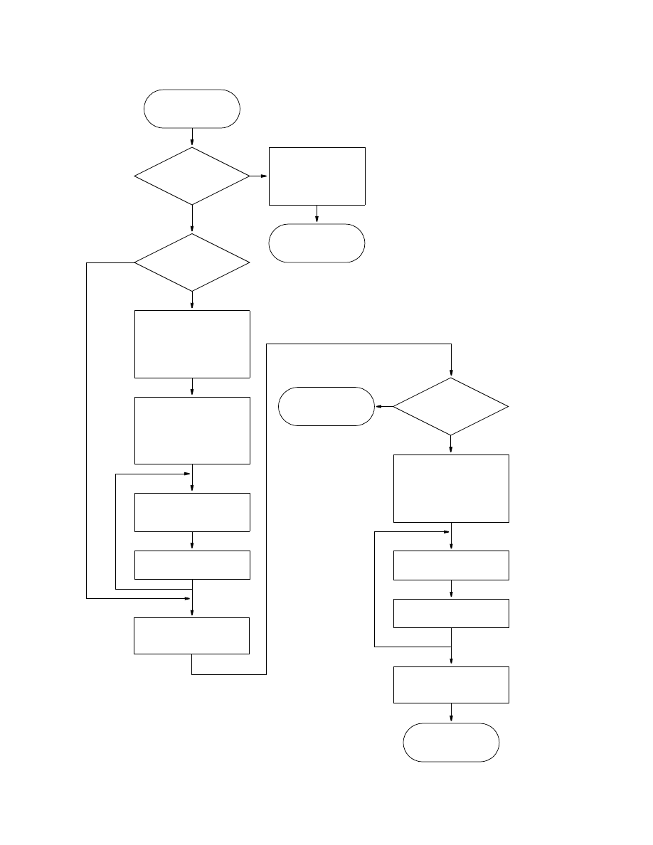
36 Documentation of a Computer Program (FHB1) to Simulate Specified-Flow and Specified-Head Boundaries
Flowchart for Module FHB1AD
ISS
≠
0 or
NBDTIM = 1
Yes
RETURN
ENTER FHB1AD
11
No
Compute area under
specified-flow curve from
ISS is a flag:
= 0 means simulation is transient.
≠
0 means simulation is steady state.
NBDTIM is the number of times used to
define functions of flow and head.
NFLW is number of specified-flow
cells.
T1 is time at start of current time step.
T2 is time at end of current time step.
HNEW is an array containing head at
each model cell at end of current
time step.
HOLD is an array containing head at
each model cell at end of previous
time step.
NHED is number of specified-head
cells.
FOR EACH
SPECIF
IED-FLOW C
E
L
L
RETURN
Set values at
specified-flow and
specified-head cells
for entire simulation
?
1
time T1 to time T2
Find indices of times
around time at start of
current time step
NFLW < 1
?
Yes
No
and compute factor for
interpolation or
extrapolation of flow
2, 3
Find indices of times
around time at end of
current time step
and compute factor for
interpolation or
extrapolation of flow
4,5
Divide area by DELT to
get rate for current step
6
Find indices of times
around time at end of
current time step
and compute factor for
interpolation or
extrapolation of head
8
Interpolate or
extrapolate head
9
Set HNEW and HOLD
equal to computed head
NHED < 1
?
Yes
No
RETURN
FOR EACH
SPECIFIED-HEAD CEL
L
Compute values of
auxiliary variables for
10
specified-head cells
Compute values of
auxiliary variables for
7
specified-flow cells

FHB1AD
37
Program Listing for Module FHB1AD
SUBROUTINE FHB1AD(HNEW,HOLD,NCOL,NROW,NLAY,ISS,TOTIM,DELT,BDTIM,
& NBDTIM,FLWRAT,BDFV,BDHV,NFLW,SBHED,IHDLOC,NHED,
& NFHBX1,NFHBX2,IFHBD3,IFHBD4,IFHBD5)
C
C------VERSION 0000 10JAN1997 FHB1AD
C ******************************************************************
C COMPUTE SPECIFIED FLOWS AND HEADS AT CURRENT TIME STEP
C ******************************************************************
C
C SPECIFICATIONS:
C ------------------------------------------------------------------
COMMON /FHBCOM/ FHBXNM(10),FHBXWT(10)
CHARACTER*16 FHBXNM
DOUBLE PRECISION HNEW
C
DIMENSION BDTIM(NBDTIM),FLWRAT(IFHBD3,NFLW),BDFV(IFHBD4,NFLW),
& BDHV(NFHBX2,NHED),SBHED(IFHBD5,NHED),IHDLOC(4,NHED),
& HNEW(NCOL,NROW,NLAY),HOLD(NCOL,NROW,NLAY)
C ------------------------------------------------------------------
C
C1------IF THIS IS A STEADY-STATE SIMULATION OR A TRANSIENT SIMULATION
C1------WITH CONSTANT SPECIFIED FLOWS AND HEADS, SET VALUES AND RETURN
IF(ISS.NE.0.OR.NBDTIM.EQ.1) THEN
IF(NFLW.LT.1) GO TO 6
DO 5 NF=1,NFLW
BDFV(1,NF)=FLWRAT(1,NF)
IF(NFHBX1.LT.1) GO TO 5
DO 4 NX=1,NFHBX1
N1=2+NX
N2=1+NX*NBDTIM
BDFV(N1,NF)=FLWRAT(N2,NF)
4 CONTINUE
5 CONTINUE
6 IF(NHED.LT.1) RETURN
DO 10 NH=1,NHED
K=IHDLOC(1,NH)
I=IHDLOC(2,NH)
J=IHDLOC(3,NH)
HNEW(J,I,K)=SBHED(1,NH)
HOLD(J,I,K)=SBHED(1,NH)
IF(NFHBX2.LT.1) GO TO 10
DO 8 NX=1,NFHBX2
N2=1+NX*NBDTIM
BDHV(NX,NF)=SBHED(N2,NF)
8 CONTINUE
10 CONTINUE
RETURN
ENDIF
C
C2------FIND ARRAY INDICES OF TIMES AROUND TIME AT START OF CURRENT
C2------TIME STEP
IF(NFLW.LT.1) GO TO 200
T2=TOTIM

38 Documentation of a Computer Program (FHB1) to Simulate Specified-Flow and Specified-Head Boundaries
T1=TOTIM-DELT
DO 20 L=2,NBDTIM
IF(T1.LE.BDTIM(L)) THEN
IB1=L-1
IB2=L
GO TO 40
ENDIF
20 CONTINUE
IB1=NBDTIM-1
IB2=NBDTIM
C
C3------COMPUTE FACTOR FOR INTERPOLATION OR EXTRAPOLATION OF FLOW AT
C3------START OF CURRENT TIME STEP
40 QFACT1=(T1-BDTIM(IB1))/(BDTIM(IB2)-BDTIM(IB1))
C
C4------FIND ARRAY INDICES OF TIMES AROUND TIME AT END OF CURRENT
C4------TIME STEP
DO 60 L=IB2,NBDTIM
IF(T2.LE.BDTIM(L)) THEN
IB3=L-1
IB4=L
GO TO 70
ENDIF
60 CONTINUE
IB4=NBDTIM
IB3=NBDTIM-1
C
C5------COMPUTE FACTOR FOR INTERPOLATION OR EXTRAPOLATION OF FLOW AT
C5------END OF CURRENT TIME STEP
70 QFACT2=(T2-BDTIM(IB3))/(BDTIM(IB4)-BDTIM(IB3))
C
C6------COMPUTE SPECIFIED FLOW RATES FOR THIS TIME STEP
NPI=IB4-IB2
DO 90 NF=1,NFLW
QA=FLWRAT(IB1,NF)
QB=FLWRAT(IB2,NF)
QC=FLWRAT(IB3,NF)
QD=FLWRAT(IB4,NF)
Q1=(QA+QFACT1*(QB-QA))
Q2=(QC+QFACT2*(QD-QC))
IF(NPI.EQ.0) THEN
BDFV(1,NF)=0.5*(Q1+Q2)
ELSE
TP=T1
QP=Q1
SUM1=0.0
DO 80 NI=IB2,IB3
QN=FLWRAT(NI,NF)
DDT=BDTIM(NI)-TP
SUM1=SUM1+DDT*0.5*(QN+QP)
TP=BDTIM(NI)
QP=QN
80 CONTINUE
DDT=T2-TP
SUM1=SUM1+DDT*0.5*(Q2+QP)

FHB1AD
39
BDFV(1,NF)=SUM1/DELT
ENDIF
90 CONTINUE
C
C7-----COMPUTE VALUES OF AUXILIARY VARIABLES FOR SPECIFIED-FLOW
C7-----CELLS FOR CURRENT TIME STEP
IF(NFHBX1.LT.1) GO TO 200
DO 190 NX=1,NFHBX1
N1=2+NX
N2=NX*NBDTIM
TT=TOTIM-(1.-FHBXWT(NX))*DELT
DO 120 L=2,NBDTIM
IF(TT.LE.BDTIM(L)) THEN
IB1=L-1
IB2=L
GO TO 140
ENDIF
120 CONTINUE
IB1=NBDTIM-1
IB2=NBDTIM
140 XFACT=(TT-BDTIM(IB1))/(BDTIM(IB2)-BDTIM(IB1))
DO 150 NF=1,NFLW
XX=FLWRAT(N2+IB1,NF)+XFACT*(FLWRAT(N2+IB2,NF)-FLWRAT(N2+IB1,NF))
BDFV(N1,NF)=XX
150 CONTINUE
190 CONTINUE
C8------FIND ARRAY INDICES OF TIMES AROUND TIME AT END OF CURRENT
C8------TIME STEP, COMPUTE FACTOR OF INTERPOLATION OR EXTRAPOLATION
C8------OF HEAD
200 IF(NHED.LT.1) RETURN
TT=TOTIM
DO 220 L=2,NBDTIM
IF(TT.LE.BDTIM(L)) THEN
IB1=L-1
IB2=L
GO TO 240
ENDIF
220 CONTINUE
IB1=NBDTIM-1
IB2=NBDTIM
240 HFACT=(TT-BDTIM(IB1))/(BDTIM(IB2)-BDTIM(IB1))
C
C9------AT EACH SPECIFIED-HEAD LOCATION, INTERPOLATE OR EXTRAPOLATE
C9------HEAD. SET HNEW AND HOLD EQUAL TO COMPUTED HEAD
DO 250 NH=1,NHED
K=IHDLOC(1,NH)
I=IHDLOC(2,NH)
J=IHDLOC(3,NH)
HH=SBHED(IB1,NH)+HFACT*(SBHED(IB2,NH)-SBHED(IB1,NH))
HNEW(J,I,K)=HH
HOLD(J,I,K)=HH
250 CONTINUE
C
C10----COMPUTE VALUES OF AUXILIARY VARIABLES FOR SPECIFIED-HEAD
C10----CELLS FOR CURRENT TIME STEP

40 Documentation of a Computer Program (FHB1) to Simulate Specified-Flow and Specified-Head Boundaries
IF(NFHBX2.LT.1) RETURN
DO 390 NX=1,NFHBX2
N2=NX*NBDTIM
TT=TOTIM-(1.-FHBXWT(5+NX))*DELT
DO 320 L=2,NBDTIM
IF(TT.LE.BDTIM(L)) THEN
IB1=L-1
IB2=L
GO TO 340
ENDIF
320 CONTINUE
IB1=NBDTIM-1
IB2=NBDTIM
340 XFACT=(TT-BDTIM(IB1))/(BDTIM(IB2)-BDTIM(IB1))
DO 350 NF=1,NHED
XX=SBHED(N2+IB1,NF)+XFACT*(SBHED(N2+IB2,NF)-SBHED(N2+IB1,NF))
BDHV(NX,NF)=XX
350 CONTINUE
390 CONTINUE
C
C11------RETURN
RETURN
END

FHB1AD
41
List of Variables for Module FHB1AD
Variable
Range
Definition
BDFV
Package DIMENSION(IFHBD3,NFLW), Computed flow and values of auxiliary variables
for each of NFLW specified-flow cells for current time step.
BDHV
Package DIMENSION(IFHBD3,NFLW), Computed values of auxiliary variables for each
of NHED specified-head cells for current time step.
BDTIM
Package DIMENSION(NBDTIM), Individual times at which values of specified flow and
specified head read by package will be applied.
DDT
Module
Time interval used in integrating under specified-flow function.
DELT
Global
Length of current time step.
FHBXNM
Package CHARACTER*16(10), Names of auxiliary variables.
FHBXWT
Package DIMENSION(10), Time-weighting factor for auxiliary variables.
FLWRAT
Package DIMENSION(NBDTIM,NFLW), Specified-flow rates for each of NFLW
specified-flow cells for each of NBDTIM simulation times.
HFACT
Module
Coefficient in equation that interpolates head at end of current time step.
HH
Module
Temporary storage of computed head at end of current time step.
HNEW
Global
DIMENSION(NCOL,NROW,NLAY), Head at each model cell at end of current
time step.
HOLD
Global
DIMENSION(NCOL,NROW,NLAY), Head at each model cell at end of previous
time step.
I
Module
Temporary storage of model row index for specified-flow and specified-head cells.
IB1
Module
Index of specified-flow time that immediately precedes time at start of current time
step.
IB2
Module
Index of specified-flow time that immediately succeeds time at start of current time
step.
IB3
Module
Index of specified-flow time that immediately precedes time at end of current time
step.
IB4
Module
Index of specified-flow time that immediately succeeds time at end of current time
step.
IFHBD3
Package Dimension for storing specified-flow values and auxiliary-variable values
associated with specified-flow cells.
IFHBD4
Package Dimension for interpolated specified-flow values and interpolated auxiliary-
variable values associated with specified-flow cells.
IFHBD5
Package Dimension for storing auxiliary-variable values associated with specified-head
cells.
IFHBSS
Package Option flag for steady-state simulations:
= 0
Take flow, head, and auxiliary-variable values at starting time.
≠
0
Interpolate flow, head, and auxiliary-variable values.
IHDLOC
Package DIMENSION(3,NHED), Layer, row, and column indices for each of NHED
specified-head cells.
ISS
Global
Flag:
= 0, simulation is transient
≠
0, simulation is steady state.
J
Module
Temporary storage of model column index for specified-flow and specified-head
cells.
K
Module
Temporary storage of model layer index for specified-flow and specified-head
cells.
L
Module
Index for time.
N1
Module
Starting point of list of auxiliary-variable values in array BDFV.
N2
Module
Starting point of list of interpolated auxiliary-variable values in array FLWRAT.

42 Documentation of a Computer Program (FHB1) to Simulate Specified-Flow and Specified-Head Boundaries
List of Variables for Module FHB1AD—Continued
Variable
Range
Definition
NBDTIM
Package Number of times used to define functions of flow and head.
NCOL
Global
Number of columns in the model grid.
NF
Module
Index for specified-flow cells.
NFHBX1
Package Number of auxiliary variables associated with specified-flow cells.
NFHBX2
Package Number of auxiliary variables associated with specified-head cells.
NFLW
Package Number of specified-flow cells.
NH
Module
Index for specified-head cells.
NHED
Package Number of specified-head cells.
NI
Module
Index for specified-flow times.
NLAY
Global
Number of layers in the model grid.
NPI
Package Number of intermediate time points between T1 and T2.
NROW
Global
Number of rows in the model grid.
NX
Module
Index for auxiliary variables.
Q1
Module
Interpolated flow at start of time step.
Q2
Module
Interpolated flow at end of time step.
QA
Module
Specified-flow value at time that immediately precedes time at start of current time
step.
QB
Module
Specified-flow value at time that immediately succeeds time at start of current time
step.
QC
Module
Specified-flow value at time that immediately precedes time at end of current time
step.
QD
Module
Specified-flow value at time that immediately succeeds time at end of current time
step.
QFACT1
Module
Coefficient in equation that interpolates head at start of current time step.
QFACT2
Module
Coefficient in equation that interpolates head at end of current time step.
QN
Module
Temporary storage of flow rate at specified-flow times between T1 and T2.
QP
Module
Flow rate at the previous interpolation point.
SBHED
Package DIMENSION(NBDTIM,NHED), Specified-head values for each of NHED
specified-head cells for each of NBDTIM simulation times.
SUM1
Module
Cumulative volume of flow from time T1 to interpolation point.
T1
Module
Time at start of current time step.
T2
Module
Time at end of current time step.
TOTIM
Global
Elapsed time in the simulation.
TP
Module
Time at previous interpolation point.
TT
Module
Temporary storage of time at end of current time step.
XFACT
Module
Coefficient in equation that interpolates values of auxiliary variables for current
time step.
XX
Module
Temporary storage of value of auxiliary variable for current time step.
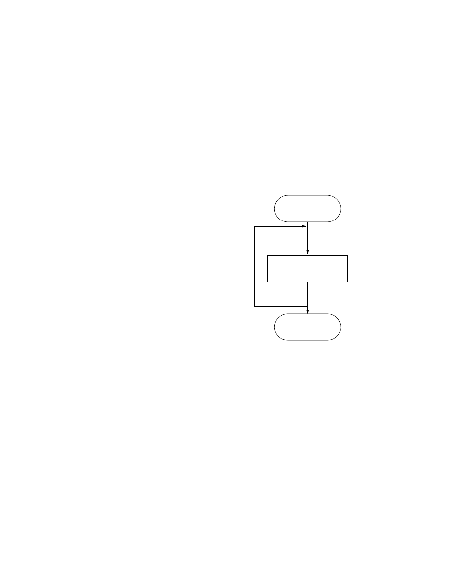
FHB1FM
43
FHB1FM
Narrative for Module FHB1FM
This module subtracts computed flow rates from the right-hand side of the finite-difference equations
for all specified-flow cell locations. Operations are carried out in the following order:
1. For each specified-flow cell location where IBOUND is greater than zero, subtract flow rate from
RHS.
2. RETURN.
Flowchart for Module FHB1FM
ENTER FHB1FM
2
Subtract specified
flow from RHS
RHS is an array containing the right-hand
side of finite-difference equations.
FOR EACH
SPECIFI
ED-FLOW CEL
L
1
RETURN

44 Documentation of a Computer Program (FHB1) to Simulate Specified-Flow and Specified-Head Boundaries
Program Listing for Module FHB1FM
SUBROUTINE FHB1FM(RHS,IBOUND,IFLLOC,BDFV,NFLW,NCOL,NROW,NLAY,
& IFHBD4)
C
C-----VERSION 0000 10JAN1997 FHB1FM
C
C ******************************************************************
C SUBTRACT SPECIFIED Q FROM RHS
C ******************************************************************
C
C SPECIFICATIONS:
C ------------------------------------------------------------------
DIMENSION RHS(NCOL,NROW,NLAY),IBOUND(NCOL,NROW,NLAY),
1 IFLLOC(4,NFLW),BDFV(IFHBD4,NFLW)
C ------------------------------------------------------------------
C
C1------PROCESS EACH SPECIFIED-FLOW LOCATION IN THE LIST.
IF(NFLW.LE.0) RETURN
DO 100 L=1,NFLW
IR=IFLLOC(2,L)
IC=IFLLOC(3,L)
IL=IFLLOC(1,L)
Q=BDFV(1,L)
C
C1A-----IF THE CELL IS INACTIVE THEN BYPASS PROCESSING.
IF(IBOUND(IC,IR,IL).LE.0) GO TO 100
C
C1B-----IF THE CELL IS VARIABLE HEAD THEN SUBTRACT Q FROM
C THE RHS ACCUMULATOR.
RHS(IC,IR,IL)=RHS(IC,IR,IL)-Q
100 CONTINUE
C
C2------RETURN
RETURN
END

FHB1FM
45
List of Variables for Module FHB1FM
Variable
Range
Definition
BDFV
Package DIMENSION(IFHBD3,NFLW), Computed flow and values of auxiliary variables
for each of NFLW specified-flow cells for current time step.
IBOUND
Global
DIMENSION(NCOL,NROW,NLAY), Status of each cell:
< 0
Constant-head cell.
= 0
No-flow cell.
> 0
Variable-head cell.
IC
Module
Temporary storage of model row location for specified-flow cells.
IFHBD4
Package Dimension for interpolated specified-flow values and interpolated auxiliary-
variable values associated with specified-flow cells.
IFLLOC
Package DIMENSION(3,NFLW), Layer, row, and column location, and integer
auxiliary-variable value for each of NFLW specified-flow cells.
IL
Module
Temporary storage of model-layer location for specified-flow cells.
IR
Module
Temporary storage of model-row location for specified-flow cells.
L
Module
Index for specified-flow cells.
NCOL
Global
Number of columns in the model grid.
NFLW
Package Number of specified-flow cells.
NLAY
Global
Number of layers in the model grid.
NROW
Global
Number of rows in the model grid.
Q
Module
Temporary storage of flow at specified-flow cells.
RHS
Global
DIMENSION(NCOL,NROW,NLAY), Right-hand side of finite-difference
equations.

46 Documentation of a Computer Program (FHB1) to Simulate Specified-Flow and Specified-Head Boundaries
FHB1BD
Narrative for Module FHB1BD
This module incorporates specified-flow rates into the overall mass balance and writes cell-by-cell flow
rates if option is selected. Operations are carried out in the following order:
1. Initialize the cell-by-cell flow term and flag, and clear the accumulators for specified-flow rates.
2. If cell-by-cell flow terms are to be saved as a list, then write header. If cell-by-cell flow terms are to
be saved as an array, clear the buffer (BUFF) in which they will be accumulated before saving.
3. Process specified-flow cells one at a time. Skip budget calculations altogether if there are no
specified-flow cells. Skip processing for any no-flow or constant-head cell.
4. Get flow rate for specified-flow cell from the BDFV array. Print rate if requested (IFHBCB<0 and
ICBCFL
≠
0). Add rate to appropriate location in buffer.
5. Add rate to appropriate inflow or outflow accumulator. If rate is positive (recharge), add rate to
accumulator RATIN. If rate is negative (discharge), add rate to accumulator RATOUT.
6. If cell-by-cell flow terms are to be saved as a list, write record with list information. Save the flow
rate in the second column of the BDFV array. If cell-by-cell flow rates are to be saved as an array,
call UBDSV to record array with rates for each cell.
7. Move rates into VBVL for printing of overall budget by module BAS1OT. Move flow volumes
(products of rates and length of current time step) into VBVL accumulators. Move budget-term labels
into VBNM for printing of overall budget by module BAS1OT.
8. Increment budget-term counter, MSUM.
9. RETURN.
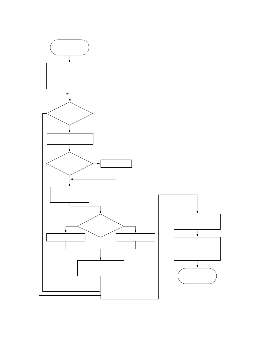
FHB1BD
47
Flowchart for Module FHB1BD
Initialize flag, IBD, and
rate accumulators. If cell-
1,2
RETURN
ENTER FHB1BD
14
Calculate volumes and
move rates, volumes, and
labels into arrays.
8-9
Print flow rate
Cell no-flow or
constant head
Yes
?
3
No
If cell-by-cell rates
by-cell terms are to be
saved, set IBD, write
header for list output
Increment budget
term counter
If cell-by-cell terms are to
be saved, write list
buffer to disk
Rate positive
Yes
No
Add rate to RATIN
?
Add rate to RATOUT
7
FOR EACH SPECI
FIED-FL
O
W
CELL
BDFV is an array containing computed flow and
values of auxiliary variables for each of
NFLW specified-flow cells for current time
step.
IBD is a flag:
= 0, cell-by-cell flow terms will not be
recorded.
≠
0, cell-by-cell flow terms will be recorded.
IFHBCB is a flag and a unit number:
> 0, unit number on which cell-by-cell flow
terms will be recorded whenever
ICBCFL is set.
= 0, cell-by-cell flow terms will not be
recorded or printed.
< 0, cell-by-cell flow terms will be printed
whenever ICBCFL is set.
ICBCFL is a flag:
= 0, cell-by-cell flow terms will not be
recorded or printed for the current time
step.
≠
0, cell-by-cell flow terms will be recorded
or printed for the current time step.
RATOUT is an accumulator to which all flows
out of the ground-water system are added.
RATIN is an accumulator to which all flows into
the ground-water system are added.
IFHBCB < 0 and
ICBCFL
≠
0
Yes
?
No
are to be saved,
add rate to buffer
and clear the buffer.
Get flow rate for cell
from the BDFV array
4
5
If cell-by-cell terms are to
be saved as a list,
write record to disk
6

48 Documentation of a Computer Program (FHB1) to Simulate Specified-Flow and Specified-Head Boundaries
Program Listing for Module FHB1BD
SUBROUTINE FHB1BD(IFLLOC,BDFV,NFLW,VBNM,VBVL,MSUM,IBOUND,DELT,
& NCOL,NROW,NLAY,KSTP,KPER,IFHBCB,ICBCFL,BUFF,IOUT,IFHBD4)
C
C-----VERSION 0000 10JAN1997 FHB1BD
C ******************************************************************
C CALCULATE VOLUMETRIC BUDGET FOR SPECIFIED FLOWS
C ******************************************************************
C
C SPECIFICATIONS:
C ------------------------------------------------------------------
CHARACTER*16 VBNM(MSUM),TEXT
DOUBLE PRECISION RATIN,RATOUT,QQ
DIMENSION VBVL(4,MSUM),IBOUND(NCOL,NROW,NLAY),
1 BUFF(NCOL,NROW,NLAY),IFLLOC(4,NFLW),BDFV(IFHBD4,NFLW)
C
DATA TEXT/’ SPECIFIED FLOWS’/
C ------------------------------------------------------------------
C
C1------CLEAR RATIN AND RATOUT ACCUMULATORS.
ZERO=0.
RATIN=ZERO
RATOUT=ZERO
IBD=0
IF(IFHBCB.LT.0 .AND. ICBCFL.NE.0) IBD=-1
IF(IFHBCB.GT.0) IBD=ICBCFL
C
C2A----IF CELL-BY-CELL FLOWS WILL BE SAVED AS A LIST, WRITE HEADER.
IF(IBD.EQ.2) CALL UBDSV2(KSTP,KPER,TEXT,IFHBCB,NCOL,NROW,NLAY,
1 NFLW,IOUT,DELT,PERTIM,TOTIM,IBOUND)
C
C2B----CLEAR THE BUFFER.
DO 50 IL=1,NLAY
DO 50 IR=1,NROW
DO 50 IC=1,NCOL
BUFF(IC,IR,IL)=ZERO
50 CONTINUE
C
C3A----IF THERE ARE NO SPECIFIED-FLOW CELLS, DO NOT ACCUMULATE FLOW
IF(NFLW.EQ.0) GO TO 200
C
C3B-----PROCESS SPECIFIED-FLOW CELLS ONE AT A TIME.
60 DO 100 L=1,NFLW
C
C3C-----GET LAYER, ROW, AND COLUMN NUMBERS
IR=IFLLOC(2,L)
IC=IFLLOC(3,L)
IL=IFLLOC(1,L)
Q=ZERO
C
C3D-----IF THE CELL IS NO-FLOW OR CONSTANT-HEAD, IGNORE IT.
IF(IBOUND(IC,IR,IL).LE.0)GO TO 97
C
C4A-----GET FLOW RATE FROM SPECIFIED-FLOW LIST

FHB1BD
49
Q=BDFV(1,L)
QQ=Q
C
C4B-----PRINT THE INDIVIDUAL RATES IF REQUESTED(IFHBCB<0).
IF(IBD.LT.0) THEN
WRITE(IOUT,900) TEXT,KPER,KSTP,L,IL,IR,IC,Q
900 FORMAT(1H0,4A4,’ PERIOD’,I3,’ STEP’,I3,’ SEQ NO’,I4,
1 ‘ LAYER’,I3,’ ROW ‘,I4,’ COL’,I4,’ RATE’,G15.7)
ENDIF
C
C4C-----ADD FLOW RATE TO BUFFER.
BUFF(IC,IR,IL)=BUFF(IC,IR,IL)+Q
C
C5A-----SEE IF FLOW RATE IS NEGATIVE, ZERO, OR POSITIVE.
IF(Q) 90,97,80
C
C5B-----FLOW RATE IS POSITIVE (RECHARGE). ADD IT TO RATIN.
80 RATIN=RATIN+QQ
GO TO 97
C
C5C-----FLOW RATE IS NEGATIVE(DISCHARGE). ADD IT TO RATOUT.
90 RATOUT=RATOUT-QQ
C
C6------IF CELL-BY-CELL FLOWS ARE BEING SAVED AS A LIST, WRITE FLOW.
C6------RETURN THE ACTUAL FLOW IN THE BDFV ARRAY.
97 IF(IBD.EQ.2) CALL UBDSVA(IFHBCB,NCOL,NROW,IC,IR,IL,Q,IBOUND,NLAY)
BDFV(2,L)=Q
100 CONTINUE
C
C7------IF CELL-BY-CELL FLOWS WILL BE SAVED AS A 3-D ARRAY,
C7------CALL UBUDSV TO SAVE THEM
IF(IBD.EQ.1) CALL UBUDSV(KSTP,KPER,TEXT,IFHBCB,BUFF,NCOL,NROW,
1 NLAY,IOUT)
C
C8------MOVE RATES, VOLUMES & LABELS INTO ARRAYS FOR PRINTING.
200 RIN=RATIN
ROUT=RATOUT
VBVL(3,MSUM)=RIN
VBVL(4,MSUM)=ROUT
VBVL(1,MSUM)=VBVL(1,MSUM)+RIN*DELT
VBVL(2,MSUM)=VBVL(2,MSUM)+ROUT*DELT
VBNM(MSUM)=TEXT
C
C9------INCREMENT BUDGET TERM COUNTER (MSUM).
MSUM=MSUM+1
C
C10-----RETURN
RETURN
END

50 Documentation of a Computer Program (FHB1) to Simulate Specified-Flow and Specified-Head Boundaries
List of Variables for Module FHB1BD
Variable
Range
Definition
BDFV
Package DIMENSION(NFLW), Computed flow for each of NFLW specified-flow cells for
current time step.
BUFF
Global
DIMENSION(NCOL, NROW, NLAY), Buffer used for temporary storage of flow
rates prior to recording cell-by-cell budgets.
DELT
Global
Length of the current time step.
IBD
Module
Flag:
= 0
Cell-by-cell flow terms will not be recorded.
≠
0
Cell-by-cell flow terms will be recorded.
IBOUND
Global
DIMENSION(NCOL,NROW,NLAY), Status of each cell:
< 0
Constant-head cell.
= 0
No-flow cell.
> 0
Variable-head cell.
IC
Module
Index for columns.
ICBCFL
Global
Flag:
= 0
Cell-by-cell flow terms will not be recorded for the current time step.
≠
0
Cell-by-cell flow terms will be recorded for the current time step.
IFHBCB
Package Flag and a unit number:
> 0
Unit number on which cell-by-cell flow terms will be recorded whenever
ICBCFL is set.
= 0
Cell-by-cell flow terms will not be recorded or printed.
< 0
Cell-by-cell flow terms will be printed whenever ICBCFL is set.
IFLLOC
Package DIMENSION(3,NFLW), Layer, row, and column location, and integer
auxiliary-variable value for each of NFLW specified-flow cells.
IL
Module
Index for layers.
IOUT
Global
Primary unit number for all printed output.
IR
Module
Index for rows.
KPER
Global
Stress-period counter.
KSTP
Global
Time-step counter, reset at the start of each stress period.
L
Module
Index for specified-flow cells.
MSUM
Global
Counter for budget entries in VBVL and VBNM.
N
Module
Index for text string.
NCOL
Global
Number of columns in the model grid.
NFLW
Package Number of specified-flow cells.
NLAY
Global
Number of layers in the model grid.
NROW
Global
Number of rows in the model grid.
Q
Module
Temporary storage of flow at specified-flow cells.
RATIN
Module
Accumulator for total flow into the flow field from specified-flow cells.
RATOUT
Module
Accumulator for total flow out of the flow field into specified-flow cells.
TEXT
Module
CHARACTER*16, Label for volumetric budget and cell-by-cell budget.
VBNM
Global
CHARACTER*16(MSUM), Labels for entries in volumetric budget.
VBVL
Global
DIMENSION(4,MSUM), Entries for the volumetric budget. For flow component
N, the values in VBVL are:
(1,N), Rate for current time step into the flow field.
(2,N), Rate for current time step out of the flow field.
(3,N), Volume into the flow field during the simulation.
(4,N), Volume out of the flow field during the simulation.

References Cited
51
REFERENCES CITED
Anderson, M.P., and Woessner, W.W., 1992, Applied groundwater modeling—simulation of flow and advective
transport: San Diego, California, Academic Press, 381 p.
Harbaugh, A.W., and McDonald, M.G., 1996, User’s Documentation for MODFLOW-96, an update to the U.S.
Geological Survey modular finite-difference ground-water flow model: U.S. Geological Survey Open-File Report
96–485, 56 p.
Konikow, L.F., Goode, D.J., and Hornberger, G.Z., 1996, A three-dimensional method-of-characteristics
solute-transport model (MOC3D): U.S. Geological Survey Water-Resources Investigations Report 96–4267, 87 p.
Leake, S.A., and Prudic, D.E., 1991, Documentation of a computer program to simulate aquifer-system compaction
using the modular finite-difference ground-water flow model: U.S. Geological Survey Techniques of Water-
Resources Investigations, book 6, chap. A2, 68 p.
McDonald, M.G., and Harbaugh, A.W., 1988, A modular three-dimensional finite-difference ground-water flow
model: U.S. Geological Survey Techniques of Water-Resources Investigations, book 6, chap. A1, 586 p.
Pollock, D.W., 1994, User’s guide for MODPATH/MODPATH-PLOT, version 3: a particle tracking post-processing
package for MODFLOW, the U.S. Geological Survey finite-difference ground-water flow model: U.S. Geological
Survey Open-File Report 94–464, 234 p.
Ward, D.S., Buss, D.R., Mercer, J.W., and Hughes, S.S., 1987, Evaluation of a groundwater corrective action at the
Chem-Dyne hazardous waste site using a telescope mesh refinement modeling approach: Water Resources
Research, v. 23, no. 4, p. 603–617.

52 Documentation of a Computer Program (FHB1) to Simulate Specified-Flow and Specified-Head Boundaries
APPENDIX—Input Data Sets and Printed Results for Example Problem
Listing of MODFLOW Name file
The contents of the MODFLOW name file is given below. The input consists of 8 records (lines).
LIST 6 test7.lst
BAS 5 test7.bas
BCF 11 test7.bcf
SIP 19 test7.sip
OC 22 test7.oc
FHB 31 test7.fhb
DATA(BINARY) 41 test7.head
DATA(BINARY) 44 test7.cbc
Listing of Input Data for Basic Package
Input for the Basic Package is given below. The input consists of 14 records (lines), read from
FORTRAN unit number 5, as specified in the MAIN program.
Example problem for Flow and Head Boundary Package, Version 1 (FHB1)
From USGS Open-File Report 97–571
1 3 10 3 4
11 0 0 0 0 0 0 0 19 0 0 22 0 0 0 0 0 0 0 0 31
0 1
5 1(10I3) 3
1 1 1 1 1 1 1 1 1 1
1 1 1 1 1 1 1 1 1 1
1 1 1 1 1 1 1 1 1 1
0.0
0 0.0 Starting head
400. 10 1.0 Stress Period 1
200. 4 1.0 Stress Period 2
400. 6 1.1 Stress Period 3
Listing of Input Data for Block-Centered Flow Package
Input for the Block-Centered Flow Package is given below. The input consists of 7 records (lines),
read from FORTRAN unit number 11.
0 0
0
0 1.0 TRPY
0 1000. DELR
0 1000. DELC
0 0.01 Sf1
0 5000. Tran
Listing of Input Data for Strongly-Implicit Procedure Package
Input for the Strongly-Implicit Procedure Package is given below. The input consists of 2 records
(lines), read from FORTRAN unit number 19.
120 5 MXITER NPARM
1. .00100 1 0 5

APPENDIX
53
Listing of Input Data for Output Control Package
Input for the Output Control Package is given below. The input consists of 22 records (lines), read
from FORTRAN unit number 22.
4 4 41 42
0 1 0 1 Time Step 1
0 0 1 1 Layer 1
-2 1 0 1 Time Step 2
-3 1 0 1 Time Step 3
-4 1 0 1 Time Step 4
-5 1 0 1 Time Step 5
-6 1 0 1 Time Step 6
-7 1 0 1 Time Step 7
-8 1 0 1 Time Step 8
-9 1 0 1 Time Step 9
-10 1 0 1 Time Step 10
-11 1 0 1 Time Step 11
-12 1 0 1 Time Step 12
-13 1 0 1 Time Step 13
-14 1 0 1 Time Step 14
-15 1 0 1 Time Step 15
-16 1 0 1 Time Step 16
-17 1 0 1 Time Step 17
-18 1 0 1 Time Step 18
-19 1 0 1 Time Step 19
20 1 0 1 Time Step 20
1 0 1 0
Listing of Input Data for Flow and Head Boundary Package
Input for the General-Head Boundary Package is given below. The input consists of 34 records (lines),
read from FORTRAN unit number 31.
4 1 3 0 44 0 0
31 1. 1
0.0 307. 791. 1000.
31 1. 1
1 2 1 0 2000. 6000. 5000. 9000.
31 1. 1
1 1 10 0 0. 1. 5. 2.
1 2 10 0 0. 1. 5. 2.
1 3 10 0 0. 1. 5. 2.

54 Documentation of a Computer Program (FHB1) to Simulate Specified-Flow and Specified-Head Boundaries
Selected Parts of Printed Results for Example Problem
LISTING FILE: test7.lst
UNIT 6
OPENING test7.bas
FILE TYPE:BAS UNIT 5
OPENING test7.bcf
FILE TYPE:BCF UNIT 11
OPENING test7.sip
FILE TYPE:SIP UNIT 19
OPENING test7.oc
FILE TYPE:OC UNIT 22
OPENING test7.fhb
FILE TYPE:FHB UNIT 31
OPENING test7.head
FILE TYPE:DATA(BINARY) UNIT 41
OPENING test7.cbc
FILE TYPE:DATA(BINARY) UNIT 44
MODFLOW
U.S. GEOLOGICAL SURVEY MODULAR FINITE-DIFFERENCE GROUND-WATER FLOW MODEL
Example problem for Flow and Head Boundary Package, Version 1 (FHB1)
From USGS Open-File Report 97–571
1 LAYERS 3 ROWS 10 COLUMNS
3 STRESS PERIOD(S) IN SIMULATION
MODEL TIME UNIT IS DAYS
BAS5 -- BASIC MODEL PACKAGE, VERSION 5, 1/1/95 INPUT READ FROM UNIT 5
ARRAYS RHS AND BUFF WILL SHARE MEMORY
INITIAL HEAD WILL BE KEPT THROUGHOUT THE SIMULATION
287 ELEMENTS IN X ARRAY ARE USED BY BAS
287 ELEMENTS OF X ARRAY USED OUT OF 1500000
BCF5 -- BLOCK-CENTERED FLOW PACKAGE, VERSION 5, 9/1/93 INPUT READ FROM UNIT 11
TRANSIENT SIMULATION
HEAD AT CELLS THAT CONVERT TO DRY= 0.00000E+00
WETTING CAPABILITY IS NOT ACTIVE
LAYER LAYER-TYPE CODE INTERBLOCK T
--------------------------------------------
1 0 0 -- HARMONIC
31 ELEMENTS IN X ARRAY ARE USED BY BCF
318 ELEMENTS OF X ARRAY USED OUT OF 1500000
SIP5 -- STRONGLY IMPLICIT PROCEDURE SOLUTION PACKAGE
VERSION 5, 9/1/93 INPUT READ FROM UNIT 19
MAXIMUM OF 120 ITERATIONS ALLOWED FOR CLOSURE
5 ITERATION PARAMETERS
605 ELEMENTS IN X ARRAY ARE USED BY SIP
923 ELEMENTS OF X ARRAY USED OUT OF 1500000
FHB1 -- SPECIFIED FLOW PACKAGE, VERSION 1,12/3/96 INPUT READ FROM 31
TOTAL OF 4 TIMES WILL BE USED TO DEFINE VARIATIONS IN FLOW AND HEAD.
FLOW WILL BE SPECIFIED AT A TOTAL OF 1 CELLS.
HEAD WILL BE SPECIFIED AT A TOTAL OF 3 CELLS.
FHB STEADY-STATE OPTION FLAG WILL BE IGNORED,
SIMULATION IS TRANSIENT.
CELL-BY-CELL FLOWS WILL BE RECORDED ON UNIT 44
0 AUXILIARY VARIABLES FOR SPECIFIED-FLOW CELLS WILL
BE DEFINED BY FHB FOR USE BY OTHER PACKAGES.
0 AUXILIARY VARIABLES FOR SPECIFIED-HEAD CELLS WILL
BE DEFINED BY FHB FOR USE BY OTHER PACKAGES.
38 ELEMENTS IN X ARRAY ARE USED BY FHB1
961 ELEMENTS OF X ARRAY USED OUT OF 1500000
BOUNDARY ARRAY FOR LAYER 1
READING ON UNIT 5 WITH FORMAT: (10I3)
1 2 3 4 5 6 7 8 9 10
............................................
1 1 1 1 1 1 1 1 1 1 1
2 1 1 1 1 1 1 1 1 1 1
3 1 1 1 1 1 1 1 1 1 1
AQUIFER HEAD WILL BE SET TO 0.00000E+00 AT ALL NO-FLOW NODES (IBOUND=0).
INITIAL HEAD = 0.0000000E+00 FOR LAYER 1
OUTPUT CONTROL IS SPECIFIED EVERY TIME STEP
HEAD PRINT FORMAT CODE IS 9 DRAWDOWN PRINT FORMAT CODE IS 9
HEADS WILL BE SAVED ON UNIT 41 DRAWDOWNS WILL BE SAVED ON UNIT 42

APPENDIX
55
COLUMN TO ROW ANISOTROPY = 1.000000
DELR = 1000.000
DELC = 1000.000
PRIMARY STORAGE COEF = 0.1000000E-01 FOR LAYER 1
TRANSMIS. ALONG ROWS = 5000.000 FOR LAYER 1
SOLUTION BY THE STRONGLY IMPLICIT PROCEDURE
-------------------------------------------
MAXIMUM ITERATIONS ALLOWED FOR CLOSURE = 120
ACCELERATION PARAMETER = 1.0000
HEAD CHANGE CRITERION FOR CLOSURE = 0.10000E-02
SIP HEAD CHANGE PRINTOUT INTERVAL = 5
CALCULATE ITERATION PARAMETERS FROM MODEL CALCULATED WSEED
TIMES FOR SPECIFIED-FLOW AND HEAD VALUES WILL BE READ ON UNIT 31 AND
MULTIPLIED BY 1.000.
4 TIMES FOR SPECIFYING FLOWS AND HEADS:
1 2 3 4
------------------------------------------------
0.0000E+00 307.0 791.0 1000.
CELL INDICIES AND SPECIFIED-FLOW RATES WILL BE READ ON UNIT 31. RATES WILL
BE MULTIPLIED BY 1.000.
LAYER ROW COL IAUX FLOW RATES
-------------------------------------------------------------------
1 2 1 0 2000. 6000. 5000. 9000.
CELL INDICIES AND SPECIFIED-HEAD VALUES WILL BE READ ON UNIT 31. HEAD VALUES
WILL BE MULTIPLIED BY 1.000.
LAYER ROW COL IAUX HEAD VALUES
-------------------------------------------------------------------
1 1 10 0 0.0000E+00 1.000 5.000 2.000
1 2 10 0 0.0000E+00 1.000 5.000 2.000
1 3 10 0 0.0000E+00 1.000 5.000 2.000
STRESS PERIOD NO. 1, LENGTH = 400.0000
----------------------------------------------
NUMBER OF TIME STEPS = 10
MULTIPLIER FOR DELT = 1.000
INITIAL TIME STEP SIZE = 40.00000
AVERAGE SEED = 0.02467401
MINIMUM SEED = 0.02467401
5 ITERATION PARAMETERS CALCULATED FROM AVERAGE SEED:
0.000000E+00 0.603667E+00 0.842920E+00 0.937744E+00 0.975326E+00
VOLUMETRIC BUDGET FOR ENTIRE MODEL AT END OF TIME STEP 10 IN STRESS PERIOD 1
-----------------------------------------------------------------------------
CUMULATIVE VOLUMES L**3 RATES FOR THIS TIME STEP L**3/T
------------------ ------------------------
IN: IN:
--- ---
STORAGE = 0.0000 STORAGE = 0.0000
CONSTANT HEAD = 0.0000 CONSTANT HEAD = 0.0000
SPECIFIED FLOWS = 1777065.2500 SPECIFIED FLOWS = 5849.1738
TOTAL IN = 1777065.2500 TOTAL IN = 5849.1738
OUT: OUT:
---- ----
STORAGE = 860090.3125 STORAGE = 2264.6077
CONSTANT HEAD = 916104.8750 CONSTANT HEAD = 3582.3159
SPECIFIED FLOWS = 0.0000 SPECIFIED FLOWS = 0.0000
TOTAL OUT = 1776195.2500 TOTAL OUT = 5846.9238
IN - OUT = 870.0000 IN - OUT = 2.2500
PERCENT DISCREPANCY = 0.05 PERCENT DISCREPANCY = 0.04
TIME SUMMARY AT END OF TIME STEP 10 IN STRESS PERIOD 1
SECONDS MINUTES HOURS DAYS YEARS
-----------------------------------------------------------
TIME STEP LENGTH 3.45600E+06 57600. 960.00 40.000 0.10951
STRESS PERIOD TIME 3.45600E+07 5.76000E+05 9600.0 400.00 1.0951
TOTAL TIME 3.45600E+07 5.76000E+05 9600.0 400.00 1.0951
STRESS PERIOD NO. 2, LENGTH = 200.0000
----------------------------------------------
NUMBER OF TIME STEPS = 4
MULTIPLIER FOR DELT = 1.000
INITIAL TIME STEP SIZE = 50.00000

56 Documentation of a Computer Program (FHB1) to Simulate Specified-Flow and Specified-Head Boundaries
VOLUMETRIC BUDGET FOR ENTIRE MODEL AT END OF TIME STEP 4 IN STRESS PERIOD 2
-----------------------------------------------------------------------------
CUMULATIVE VOLUMES L**3 RATES FOR THIS TIME STEP L**3/T
------------------ ------------------------
IN: IN:
--- ---
STORAGE = 0.0000 STORAGE = 0.0000
CONSTANT HEAD = 0.0000 CONSTANT HEAD = 0.0000
SPECIFIED FLOWS = 2897313.0000 SPECIFIED FLOWS = 5446.2812
TOTAL IN = 2897313.0000 TOTAL IN = 5446.2812
OUT: OUT:
---- ----
STORAGE = 1284297.3750 STORAGE = 2075.0769
CONSTANT HEAD = 1611474.1250 CONSTANT HEAD = 3367.9297
SPECIFIED FLOWS = 0.0000 SPECIFIED FLOWS = 0.0000
TOTAL OUT = 2895771.5000 TOTAL OUT = 5443.0068
IN - OUT = 1541.5000 IN - OUT = 3.2744
PERCENT DISCREPANCY = 0.05 PERCENT DISCREPANCY = 0.06
TIME SUMMARY AT END OF TIME STEP 4 IN STRESS PERIOD 2
SECONDS MINUTES HOURS DAYS YEARS
-----------------------------------------------------------
TIME STEP LENGTH 4.32000E+06 72000. 1200.0 50.000 0.13689
STRESS PERIOD TIME 1.72800E+07 2.88000E+05 4800.0 200.00 0.54757
TOTAL TIME 5.18400E+07 8.64000E+05 14400. 600.00 1.6427
STRESS PERIOD NO. 3, LENGTH = 400.0000
----------------------------------------------
NUMBER OF TIME STEPS = 6
MULTIPLIER FOR DELT = 1.100
INITIAL TIME STEP SIZE = 51.84295
HEAD IN LAYER 1 AT END OF TIME STEP 6 IN STRESS PERIOD 3
-----------------------------------------------------------------------
1 2 3 4 5 6 7 8 9 10
...............................................................
1 7.22 6.78 6.25 5.70 5.12 4.54 3.94 3.31 2.67 2.00
2 7.65 6.87 6.27 5.70 5.13 4.54 3.94 3.31 2.67 2.00
3 7.22 6.78 6.25 5.70 5.12 4.54 3.94 3.31 2.67 2.00
VOLUMETRIC BUDGET FOR ENTIRE MODEL AT END OF TIME STEP 6 IN STRESS PERIOD 3
-----------------------------------------------------------------------------
CUMULATIVE VOLUMES L**3 RATES FOR THIS TIME STEP L**3/T
------------------ ------------------------
IN: IN:
--- ---
STORAGE = 284414.1875 STORAGE = 1836.9204
CONSTANT HEAD = 0.0000 CONSTANT HEAD = 0.0000
SPECIFIED FLOWS = 5352999.5000 SPECIFIED FLOWS = 8201.0176
TOTAL IN = 5637413.5000 TOTAL IN = 10037.9375
OUT: OUT:
---- ----
STORAGE = 1656061.7500 STORAGE = 0.0000
CONSTANT HEAD = 3979498.7500 CONSTANT HEAD = 10050.3262
SPECIFIED FLOWS = 0.0000 SPECIFIED FLOWS = 0.0000
TOTAL OUT = 5635560.5000 TOTAL OUT = 10050.3262
IN - OUT = 1853.0000 IN - OUT = -12.3887
PERCENT DISCREPANCY = 0.03 PERCENT DISCREPANCY = -0.12
TIME SUMMARY AT END OF TIME STEP 6 IN STRESS PERIOD 3
SECONDS MINUTES HOURS DAYS YEARS
-----------------------------------------------------------
TIME STEP LENGTH 7.21385E+06 1.20231E+05 2003.8 83.494 0.22859
STRESS PERIOD TIME 3.45600E+07 5.76000E+05 9600.0 400.00 1.0951
TOTAL TIME 8.64000E+07 1.44000E+06 24000. 1000.0 2.7379
Wyszukiwarka
Podobne podstrony:
LMG Package OFR 01 177
PCG2 Package OFR 90 4048
DRT1 Package OFR 00 466
HUF Package OFR 00 342
LMG Package OFR 01 177
PCG2 Package OFR 90 4048
PCG2 Package OFR 90 4048
Technologia spawania stali wysokostopowych 97 2003
Rada Ministrow oficjalna 97 03 (2)
ISM Code 97 2003
97 sherb prezentacja
KOLOKWIUM 2 zadanie wg Adamczewskiego na porownawczą 97
LEASING 97 2003
SES 97 2003
więcej podobnych podstron