Lab 9.6.3.2 Configure Multiple Interfaces
Estimated Time: 25 minutes
Number of Team Members: Two teams with four students per team.
Objective
In this lab, the student will complete the objective of configuring three PIX interfaces and configure
access through the PIX Security Appliance.
Scenario
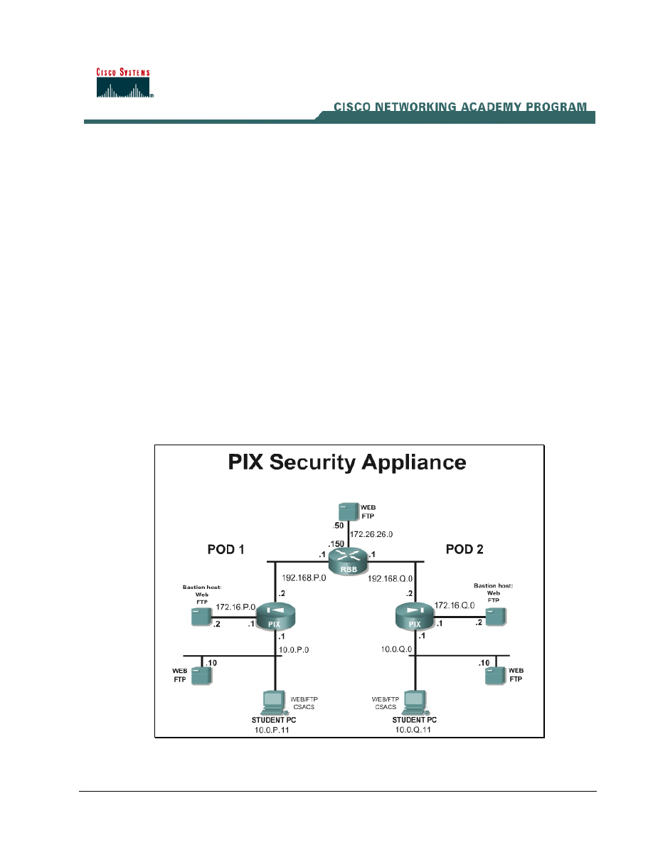
The PIX Security Appliance can be physically configured with multiple interfaces. Each of these
interfaces will have a security level somewhere between the outside interface of security level 0, and
the inside interface of security level 100. It is common to have an interface called the DMZ, for
demilitarized zone. This interface will have a security level that is between 0 and 100. A typical
application of the DMZ interface is for public servers, such as web servers.
In this lab, configure the PIX Security Appliance to allow inside and outside hosts to access the
services of a web server on the DMZ interface. Review the topology carefully before beginning.
Topology
This figure illustrates the lab network environment.
1 -
3 Fundamentals of Network Security v 1.1 - Lab 9.6.3.2 Copyright 2003, Cisco Systems, Inc.

Preparation
Begin with the standard lab topology and verify the standard configuration on the pod PIX Security
Appliances. Access the PIX Security Appliance console port using the terminal emulator on the
student PC. If desired, save the PIX Security Appliance configuration to a text file for later analysis.
Tools and resources
In order to complete the lab, the standard lab topology is required:
• Two pod PIX Security Appliances
• Two student PCs
• One SuperServer
• Backbone switch and one backbone router
• Two console cables
• HyperTerminal
Additional materials
Further information about the objectives covered in this lab can be found at
Step 1 Check Configuration
a. Erase the existing configuration.
1. What are the six basic commands to get the PIX operational?
_____________________________________________________________________________
_____________________________________________________________________________
_____________________________________________________________________________
_____________________________________________________________________________
_____________________________________________________________________________
_____________________________________________________________________________
b. Now perform or confirm the following configurations:
i. Name the appropriate interface(s) as inside, outside, and DMZ.
ii. Give each interface the appropriate IP address.
iii. Enable the Ethernet 0, Ethernet 1, and Ethernet 2 interfaces as 100-Mbps full duplex.
iv. Assign all hosts on the inside network to a Network Address Translation (NAT) pool.
v. Define a global pool of IP addresses for inside hosts to use on the outside interface. Use IP
addresses 192.168.P.20–192.168.P.254.
vi. Set a default route for all internal hosts to exit the outside interface.
vii. Allow Internet Control Message Protocol (ICMP) traffic between all interfaces.
viii. Allow FTP and WWW traffic to reach the DMZ sever.
ix. Create a static mapping for the DMZ server at 172.16.P.2 to the global IP address
192.168.P.11.
2 -
3 Fundamentals of Network Security v 1.1 - Lab 9.6.3.2 Copyright 2003, Cisco Systems, Inc.

x. Define a global pool of IP addresses for inside hosts to access the DMZ interface. Here the
interface name will be DMZ and the range of IP addresses will be 172.16.P.20-
172.16.P.254.
xi. Assign a name to a single host on the DMZ network. Since this host provides public services
that protect the inside network from external connections, call this host bastionhost. This
host has an IP address of 172.16.P.2.
xii. Test the configuration by pinging all interfaces from the console and pinging the perimeter
PIX Security Appliance from the inside host. FTP and WWW traffic should be able to reach
the DMZ server from the peer pod and from the inside host.
xiii. Use the following show commands to view information about the transaction:
• show xlate
• show conn
• show arp.
2. What do these commands reveal?
_____________________________________________________________________________
_____________________________________________________________________________
_____________________________________________________________________________
3. What
other
show commands are useful to verify configuration and operation?
_____________________________________________________________________________
_____________________________________________________________________________
_____________________________________________________________________________
3 - 3
Fundamentals of Network Security v 1.1 - Lab 9.6.3.2
Copyright
2003, Cisco Systems, Inc.
Wyszukiwarka
Podobne podstrony:
Lab9
lab9 2 6
Lab9 5 1
Rafał Polak 12k2 lab9, Inżynieria Oprogramowania - Informatyka, Semestr III, Systemy Operacyjne, Spr
i2 lab9
LAB9, 1 STUDIA - Informatyka Politechnika Koszalińska, Labki, fizyka1, fiza, fizyka
lab9 procesory sygnalowe, LABORATORIUM
lab9, Przekazywanie parametrów, struktura programu
lab9, Przekazywanie parametrów, struktura programu
JP LAB9
lab9 wielomiany ortogonalne
lab9 wielomiany ortogonalne
LAB9, Porównanie struktur i własności wybranych materiałów ceramicznych
lab9 6 3 1
lab9 3 6
wyniki(2), Elektrotechnika AGH, Semestr II letni 2012-2013, Fizyka II - Laboratorium, laborki, labor
EAP Sprawozdanie Lab9, AGH, Semestr IV, Podstawy automatyki[Ornacki,Pakuła,Łukomski,Snamina], EAP Sp
TECH INT lab9 2014, Studia - Politechnika Opolska, Semestr 6, Techniki Internetowe
lab9 6
więcej podobnych podstron