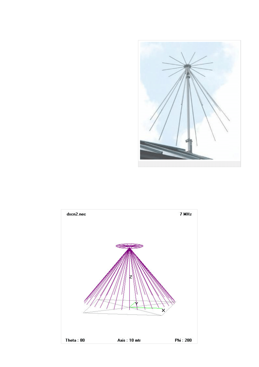
Fig. 10.5A.1 Discone antenna on the roof
10.5 Discone antenna
Basic theory
A discone antenna is a version of a biconical antenna in which one of the
cones is replaced by a disc. It is usually mounted vertically, with the disc at
the top and the cone beneath.
Omnidirectional, vertically polarized and exhibiting unity gain, it is
exceptionally wideband, offering a frequency range ratio of up to ~10:1.
The radiation pattern in the vertical plane is quite narrow, making its
sensitivity highest in the plane parallel to the Earth.
The discone's wideband coverage makes it attractive in commercial,
military, amateur radio and radio scanner applications.
When employed as a transmitting antenna, it is often less efficient than an
antenna designed for a more limited frequency range. SWR (standing wave
ratio) is typically ~2:1 over the range of the design frequency to the second
harmonic and ~3.1 thereafter.
A discone antenna typically has at least three major components: the disc,
the cone, and the insulator.
The disc should have an overall diameter of 0.7 times a quarter wavelength
of the antenna's minimum frequency. The antenna's feed point is at the
center of the disc. It is usually fed with 50 Ω coaxial cable, with the center
conductor connected to the disc, and the outer conductor to the cone.
The length of the cone should be a quarter wavelength of the antenna's
minimum operating frequency. The cone angle is generally from 25 to 40 degrees.
The disc and cone must be separated by an insulator, the dimensions of which determine some of the antenna's properties.
In order to extend low-frequency response, a vertical whip may be placed affixed vertically to the disc. But this may reduce efficiency at higher
frequencies. In this configuration, at lower frequencies the discone may more closely resemble a ground plane antenna or a coaxial dipole.
Copyright © 2010 FEEC VUT Brno All rights reserved.
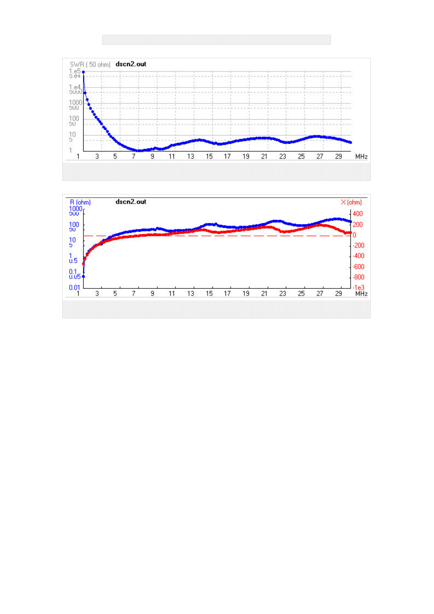
Fig. 10.5A.2 Wire model of a discone antenna
Fig. 10.5A.3 Frequency response of standing wave ratio of a discone antenna (radius of cone d = 4.2 m,
the length l = 16.8 m)
Fig. 10.5A.4 Frequency response of input impedance of a discone antenna (radius of cone d = 4.2 m, the
length l = 16.8 m)
Copyright © 2010 FEEC VUT Brno All rights reserved.
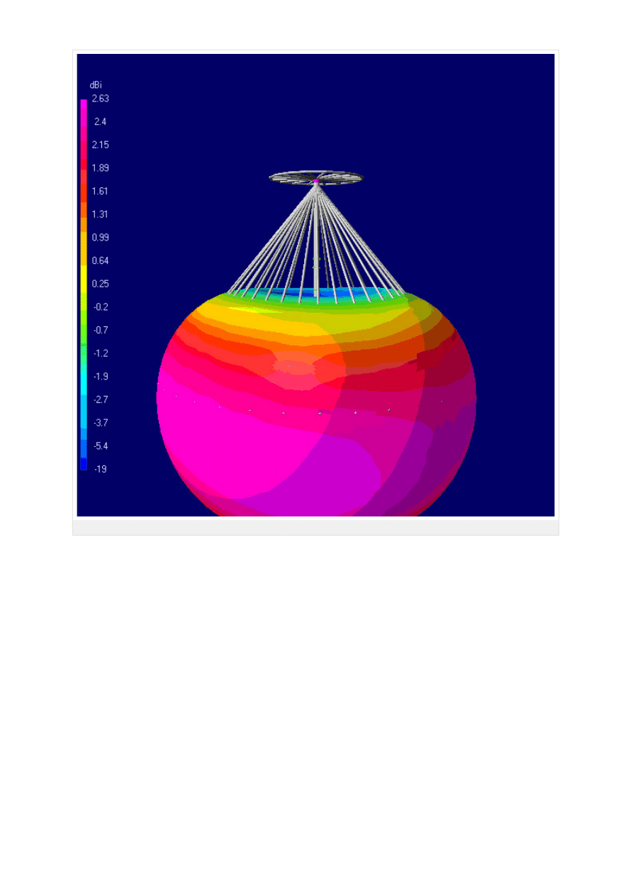
Fig. 10.5A.5 Radiation pattern of a discone antenna at 7 MHz (radius of cone d = 4.2 m, the length l = 16.8 m)
Copyright © 2010 FEEC VUT Brno All rights reserved.
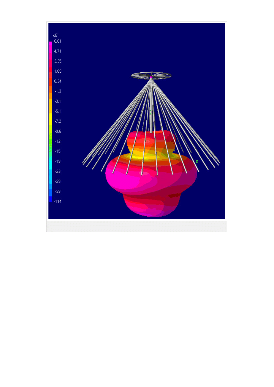
Fig. 10.5A.6 Radiation pattern of a discone antenna at 14 MHz (radius of cone d = 4.2 m, the
length l = 16.8 m)
Copyright © 2010 FEEC VUT Brno All rights reserved.
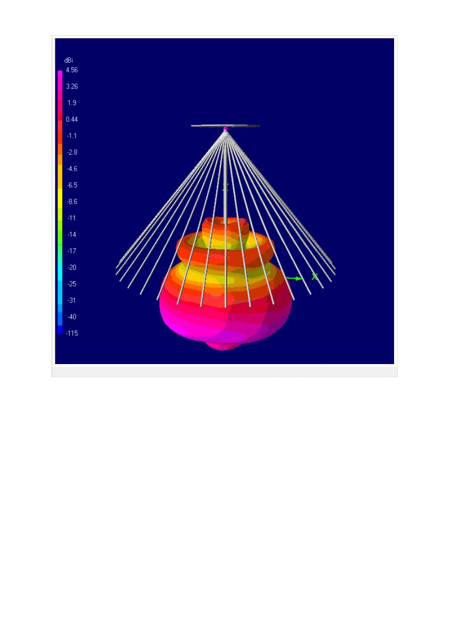
Fig. 10.5A.7 Radiation pattern of a discone antenna at 21 MHz (radius of cone d = 4.2 m, the length l = 16.8 m)
Copyright © 2010 FEEC VUT Brno All rights reserved.
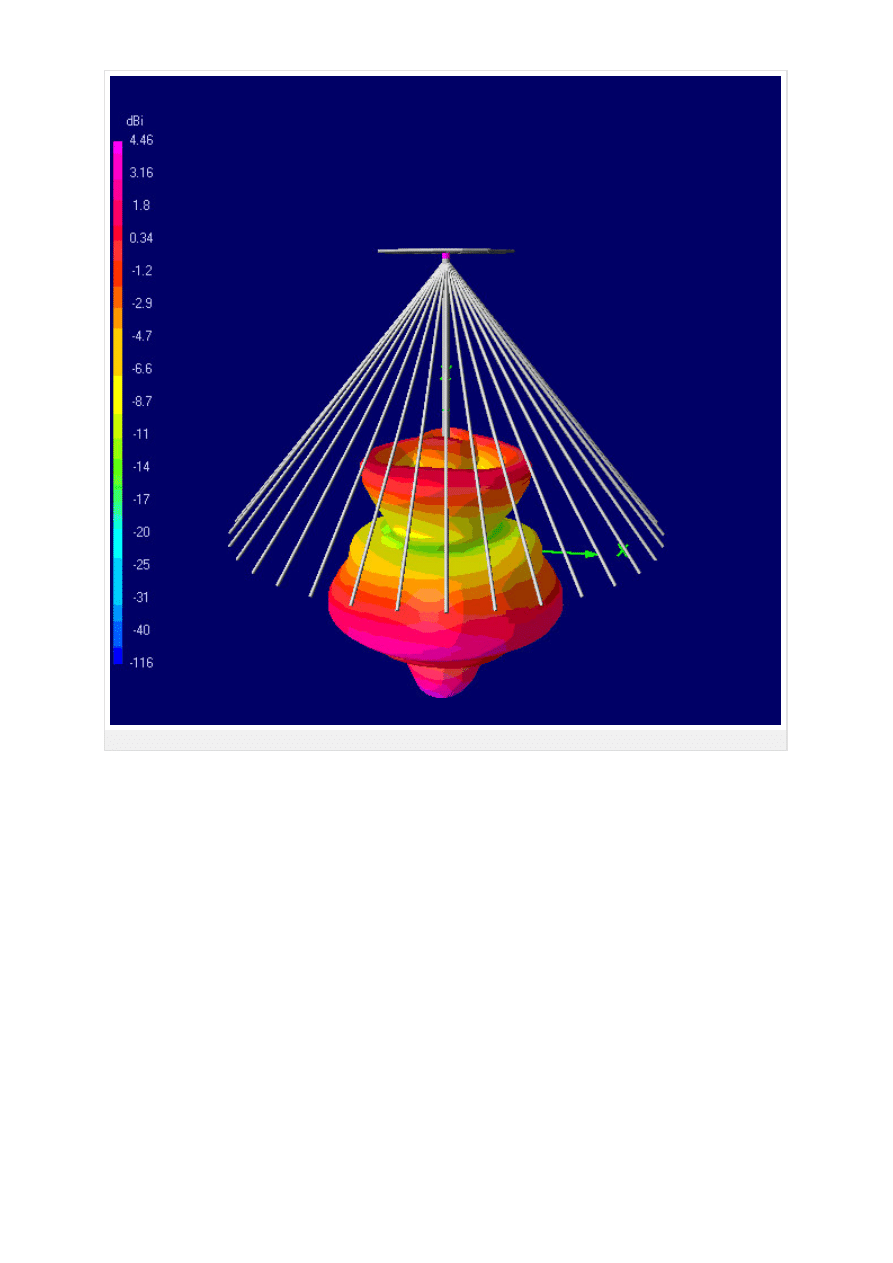
Fig. 10.5A.8 Radiation pattern of a discone antenna at 28 MHz (radius of cone d = 4.2 m, the length l = 16.8 m)
Copyright © 2010 FEEC VUT Brno All rights reserved.
Wyszukiwarka
Podobne podstrony:
10 Metody otrzymywania zwierzat transgenicznychid 10950 ppt
10 dźwigniaid 10541 ppt
wyklad 10 MNE
Kosci, kregoslup 28[1][1][1] 10 06 dla studentow
10 budowa i rozwój OUN
10 Hist BNid 10866 ppt
POKREWIEŃSTWO I INBRED 22 4 10
Prezentacja JMichalska PSP w obliczu zagrozen cywilizacyjn 10 2007
Mat 10 Ceramika
BLS 10
10 0 Reprezentacja Binarna
10 4id 10454 ppt
więcej podobnych podstron