273
CHAPTER 16
INSTRUMENTS FOR CELESTIAL NAVIGATION
THE MARINE SEXTANT
1600. Description And Use
The marine sextant measures the angle between two
points by bringing the direct ray from one point and a dou-
ble-reflected ray from the other into coincidence. Its
principal use is to measure the altitudes of celestial bodies
above the visible sea horizon. It may also be used to measure
vertical angles to find the range from an object of known
height. Sometimes it is turned on its side and used for mea-
suring the angular distance between two terrestrial objects.
A marine sextant can measure angles up to approxi-
mately 120
°
. Originally, the term “sextant” was applied to
the navigator’s double-reflecting, altitude-measuring in-
strument only if its arc was 60
°
in length, or 1/6 of a circle,
permitting measurement of angles from 0
°
to 120
°
. In mod-
ern usage the term is applied to all modern navigational
altitude-measuring instruments regardless of angular range
or principles of operation.
1601. Optical Principles Of A Sextant
When a plane surface reflects a light ray, the angle of re-
flection equals the angle of incidence. The angle between the
first and final directions of a ray of light that has undergone
double reflection in the same plane is twice the angle the two
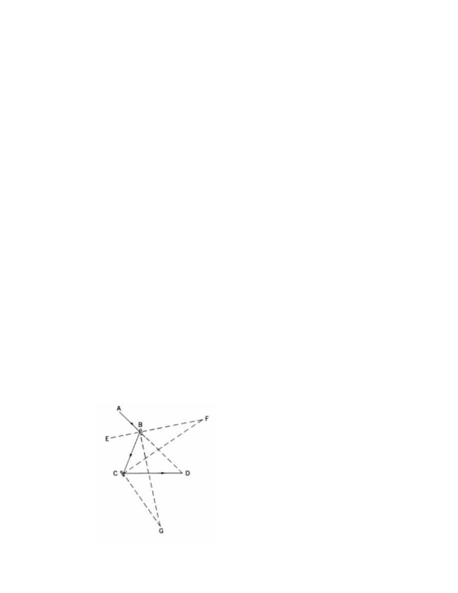
reflecting surfaces make with each other (Figure 1601).
In Figure 1601, AB is a ray of light from a celestial body.
The index mirror of the sextant is at B, the horizon glass at C,
and the eye of the observer at D. Construction lines EF and
CF are perpendicular to the index mirror and horizon glass,
respectively. Lines BG and CG are parallel to these mirrors.
Therefore, angles BFC and BGC are equal because their
sides are mutually perpendicular. Angle BGC is the inclina-
tion of the two reflecting surfaces. The ray of light AB is
reflected at mirror B, proceeds to mirror C, where it is again
reflected, and then continues on to the eye of the observer at
D. Since the angle of reflection is equal to the angle of
incidence,
Since an exterior angle of a triangle equals the sum of
the two non adjacent interior angles,
ABC = BDC+BCD, and EBC = BFC+BCF.
Transposing,
BDC = ABC-BCD, and BFC = EBC-BCF.
Substituting 2EBC for ABC, and 2BCF for BCD in the
first of these equations,
BDC = 2EBC-2BCF, or BDC=2 (EBC-BCF).
Since BFC=EBC - BCF, and BFC = BGC, therefore
BDC = 2BFC = 2BGC.
That is, BDC, the angle between the first and last direc-
tions of the ray of light, is equal to 2BGC, twice the angle
of inclination of the reflecting surfaces. Angle BDC is the
altitude of the celestial body.
If the two mirrors are parallel, the incident ray from any
observed body must be parallel to the observer’s line of sight
through the horizon glass. In that case, the body’s altitude
would be zero. The angle that these two reflecting surfaces
make with each other is one-half the observed angle. The
graduations on the arc reflect this half angle relationship be-
tween the angle observed and the mirrors’ angle.
1602. Micrometer Drum Sextant
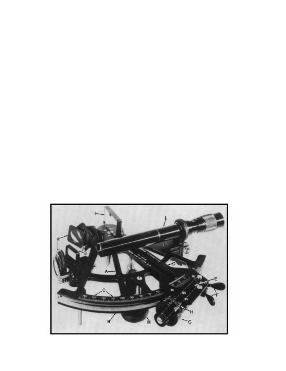
Figure 1602 shows a modern marine sextant, called a
micrometer drum sextant. In most marine sextants, brass
or aluminum comprise the frame, A. Frames come in vari-
Figure 1601. Optical principle of the marine sextant.
ABE = EBC, and ABC = 2EBC.
BCF = FCD, and BCD = 2BCF.
274
INSTRUMENTS FOR CELESTIAL NAVIGATION
ous designs; most are similar to this. Teeth mark the outer
edge of the limb, B; each tooth marks one degree of alti-
tude. The altitude graduations, C, along the limb, mark the
arc. Some sextants have an arc marked in a strip of brass,
silver, or platinum inlaid in the limb.
The index arm, D, is a movable bar of the same material
as the frame. It pivots about the center of curvature of the
limb. The tangent screw, E, is mounted perpendicularly on
the end of the index arm, where it engages the teeth of the
limb. Because the observer can move the index arm through
the length of the arc by rotating the tangent screw, this is
sometimes called an “endless tangent screw.” Contrast this
with the limited-range device on older instruments. The re-
lease, F, is a spring-actuated clamp that keeps the tangent
screw engaged with the limb’s teeth. The observer can disen-
gage the tangent screw and move the index arm along the
limb for rough adjustment. The end of the tangent screw
mounts a micrometer drum, G, graduated in minutes of al-
titude. One complete turn of the drum moves the index arm
one degree along the arc. Next to the micrometer drum and
fixed on the index arm is a vernier, H, that reads in fractions
of a minute. The vernier shown is graduated into ten parts,
permitting readings to
1
/
10
of a minute of arc (0.1'). Some
sextants (generally of European manufacture) have verniers
graduated into only five parts, permitting readings to 0.2'.
The index mirror, I, is a piece of silvered plate glass
mounted on the index arm, perpendicular to the plane of the
instrument, with the center of the reflecting surface directly
over the pivot of the index arm. The horizon glass, J, is a
piece of optical glass silvered on its half nearer the frame.
It is mounted on the frame, perpendicular to the plane of the
sextant. The index mirror and horizon glass are mounted so
that their surfaces are parallel when the micrometer drum is
set at 0
°
, if the instrument is in perfect adjustment. Shade
glasses, K, of varying darkness are mounted on the sex-
tant’s frame in front of the index mirror and horizon glass.
They can be moved into the line of sight as needed to reduce
the intensity of light reaching the eye.
The telescope, L, screws into an adjustable collar in
line with the horizon glass and parallel to the plane of the
instrument. Most modern sextants are provided with only
one telescope. When only one telescope is provided, it is of
the “erect image type,” either as shown or with a wider “ob-
ject glass” (far end of telescope), which generally is shorter
in length and gives a greater field of view. The second tele-
scope, if provided, may be the “inverting type.” The
inverting telescope, having one lens less than the erect type,
absorbs less light, but at the expense of producing an invert-
ed image. A small colored glass cap is sometimes provided,
to be placed over the “eyepiece” (near end of telescope) to
reduce glare. With this in place, shade glasses are generally
not needed. A “peep sight,” or clear tube which serves to di-
rect the line of sight of the observer when no telescope is
used, may be fitted.
Sextants are designed to be held in the right hand.
Some have a small light on the index arm to assist in read-
ing altitudes. The batteries for this light are fitted inside a
recess in the handle, M. Not clearly shown in Figure 1602
are the tangent screw, E, and the three legs.
Figure 1602. U.S. Navy Mark 2 micrometer drum sextant.

INSTRUMENTS FOR CELESTIAL NAVIGATION
275
There are two basic designs commonly used for mounting
and adjusting mirrors on marine sextants. On the U.S. Navy
Mark 3 and certain other sextants, the mirror is mounted so that
it can be moved against retaining or mounting springs within
its frame. Only one perpendicular adjustment screw is re-
quired. On the U.S. Navy Mark 2 and other sextants the mirror
is fixed within its frame. Two perpendicular adjustment screws
are required. One screw must be loosened before the other
screw bearing on the same surface is tightened.
1603. Vernier Sextant
Most recent marine sextants are of the micrometer
drum type, but at least two older-type sextants are still in
use. These differ from the micrometer drum sextant princi-
pally in the manner in which the final reading is made. They
are called vernier sextants.
The clamp screw vernier sextant is the older of the
two. In place of the modern release clamp, a clamp screw is
fitted on the underside of the index arm. To move the index
arm, the clamp screw is loosened, releasing the arm. When
the arm is placed at the approximate altitude of the body be-
ing observed, the clamp screw is tightened. Fixed to the
clamp screw and engaged with the index arm is a long tan-
gent screw. When this screw is turned, the index arm moves
slowly, permitting accurate setting. Movement of the index
arm by the tangent screw is limited to the length of the screw
(several degrees of arc). Before an altitude is measured, this
screw should be set to the approximate mid-point of its
range. The final reading is made on a vernier set in the index
arm below the arc. A small microscope or magnifying glass
fitted to the index arm is used in making the final reading.
The endless tangent screw vernier sextant is identical to
the micrometer drum sextant, except that it has no drum, and
the fine reading is made by a vernier along the arc, as with th-
eclamp screw vernier sextant. The release is the same as on the
micrometer drum sextant, and teeth are cut into the underside
of the limb which engage with the endless tangent screw.
1604. Sextant Sun Sights
Hold the sextant vertically and direct the sight line at the
horizon directly below the sun. After moving suitable shade
glasses into the line of sight, move the index arm outward
along the arc until the reflected image appears in the horizon
glass near the direct view of the horizon. Rock the sextant
slightly to the right and left to ensure it is perpendicular. As the
observer rocks the sextant, the image of the sun appears to
move in an arc, and the observer may have to turn slightly to
prevent the image from moving off the horizon glass.
The sextant is vertical when the sun appears at the bot-
tom of the arc. This is the correct position for making the
observation. The sun’s reflected image appears at the center
of the horizon glass; one half appears on the silvered part,
and the other half appears on the clear part. Move the index
arm with the drum or vernier slowly until the sun appears to
be resting exactly on the horizon, tangent to the lower limb.
The novice observer needs practice to determine the exact
point of tangency. Beginners often err by bringing the im-
age down too far.
Some navigators get their most accurate observations
by letting the body contact the horizon by its own motion,
bringing it slightly below the horizon if rising, and above if
setting. At the instant the horizon is tangent to the disk, the
navigator notes the time. The sextant altitude is the uncor-
rected reading of the sextant.
1605. Sextant Moon Sights
When observing the moon, follow the same procedure
as for the sun. Because of the phases of the moon, the upper
limb of the moon is observed more often than that of the
sun. When the terminator (the line between light and dark
areas) is nearly vertical, be careful in selecting the limb to
shoot. Sights of the moon are best made during either day-
light hours or that part of twilight in which the moon is least
luminous. At night, false horizons may appear below the
moon because the moon illuminates the water below it.
1606. Sextant Star And Planet Sights
Use one of these three methods when making the initial
altitude approximation on a star or planet:
Method 1. Set the index arm and micrometer drum on
0
°
and direct the line of sight at the body to be observed.
Then, while keeping the reflected image of the body in the
mirrored half of the horizon glass, swing the index arm out
and rotate the frame of the sextant down. Keep the reflected
image of the body in the mirror until the horizon appears in
the clear part of the horizon glass. Then, make the observa-
tion. When there is little contrast between brightness of the
sky and the body, this procedure is difficult. If the body is
“lost” while it is being brought down, it may not be recov-
ered without starting over again.
Method 2. Direct the line of sight at the body while
holding the sextant upside down. Slowly move the index-
arm out until the horizon appears in the horizon glass. Then
invert the sextant and take the sight in the usual manner.
Method 3. Determine in advance the approximate alti-
tude and azimuth of the body by a star finder such as No.
2102D. Set the sextant at the indicated altitude and face in
the direction of the azimuth. The image of the body should
appear in the horizon glass with a little searching.
When measuring the altitude of a star or planet, bring
its center down to the horizon. Stars and planets have no
discernible upper or lower limb; observe the center of the
point of light. Because stars and planets have no discernible
limb and because their visibility may be limited, the method
of letting a star or planet intersect the horizon by its own
motion is not recommended. As with the sun and moon,
however, “rock the sextant” to establish perpendicularity.
276
INSTRUMENTS FOR CELESTIAL NAVIGATION
1607. Taking A Sight
Predict expected altitudes and azimuths for up to eight
bodies when preparing to take celestial sights. Choose the
stars and planets that give the best bearing spread. Try to se-
lect bodies with a predicted altitude between 30
°
and 70
°
.
Take sights of the brightest stars first in the evening; take
sights of the brightest stars last in the morning.
Occasionally, fog, haze, or other ships in a formation
may obscure the horizon directly below a body which the
navigator wishes to observe. If the arc of the sextant is suf-
ficiently long, a back sight might be obtained, using the
opposite point of the horizon as the reference. For this the
observer faces away from the body and observes the sup-
plement of the altitude. If the sun or moon is observed in
this manner, what appears in the horizon glass to be the
lower limb is in fact the upper limb, and vice versa. In the
case of the sun, it is usually preferable to observe what ap-
pears to be the upper limb. The arc that appears when
rocking the sextant for a back sight is inverted; that is, the
highest point indicates the position of perpendicularity.
If more than one telescope is furnished with the sex-
tant, the erecting telescope is used to observe the sun. A
wider field of view is present if the telescope is not used.
The collar into which the sextant telescope fits may be ad-
justed in or out, in relation to the frame. When moved in,
more of the mirrored half of the horizon glass is visible to
the navigator, and a star or planet is more easily observed
when the sky is relatively bright. Near the darker limit of
twilight, the telescope can be moved out, giving a broader
view of the clear half of the glass, and making the less dis-
tinct horizon more easily discernible. If both eyes are kept
open until the last moments of an observation, eye strain
will be lessened. Practice will permit observations to be
made quickly, reducing inaccuracy due to eye fatigue.
When measuring an altitude, have an assistant note and
record the time if possible, with a “stand-by” warning when
the measurement is almost ready, and a “mark” at the mo-
ment a sight is made. If a flashlight is needed to see the
comparing watch, the assistant should be careful not to in-
terfere with the navigator’s night vision.
If an assistant is not available to time the observations, the
observer holds the watch in the palm of his left hand, leaving his
fingers free to manipulate the tangent screw of the sextant. After
making the observation, he notes the time as quickly as possible.
The delay between completing the altitude observation and not-
ing the time should not be more than one or two seconds.
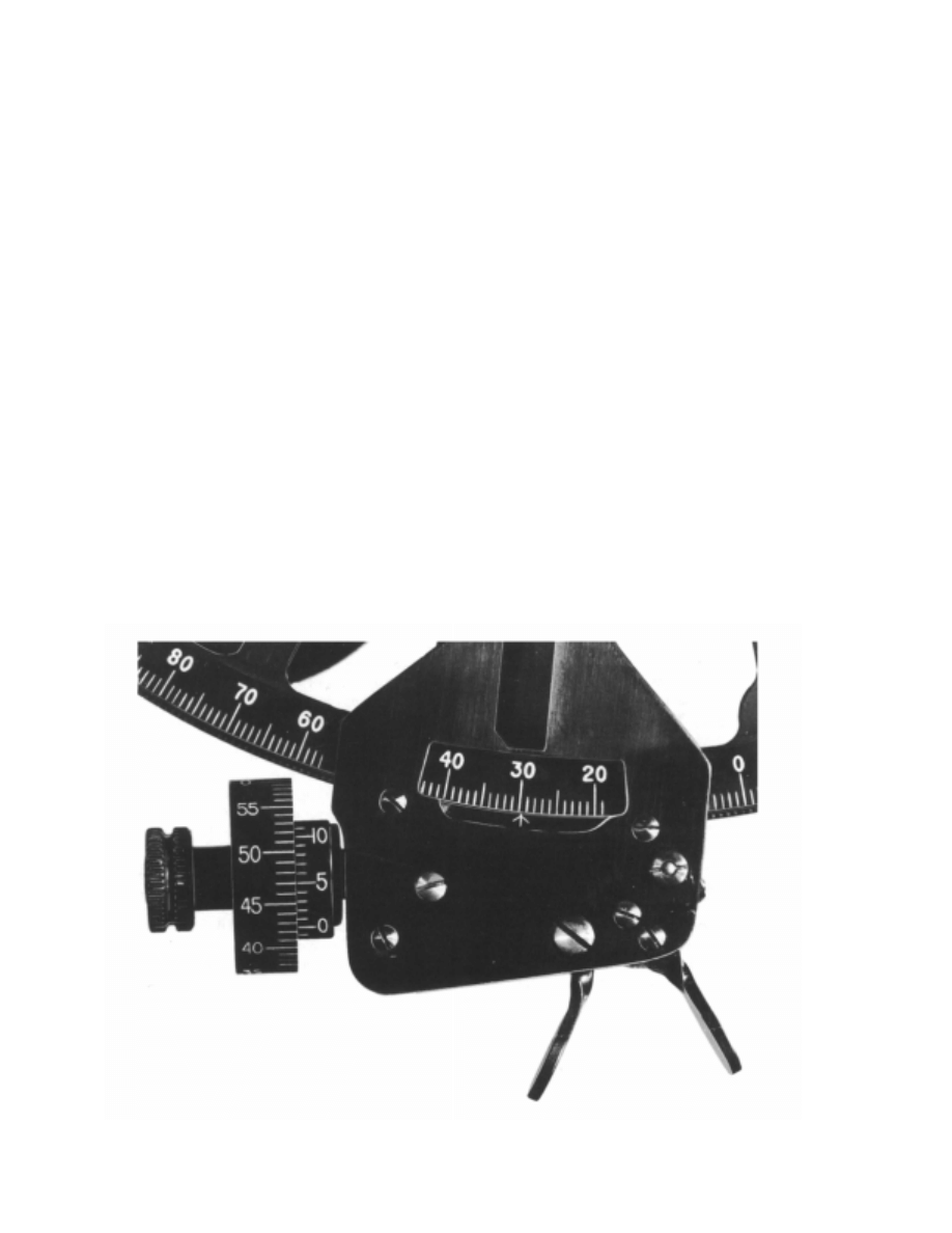
1608. Reading The Sextant
Reading a micrometer drum sextant is done in three
steps. The degrees are read by noting the position of the ar-
row on the index arm in relation to the arc. The minutes are
read by noting the position of the zero on the vernier with
Figure 1608a. Micrometer drum sextant set at 29
°
42.5'.
INSTRUMENTS FOR CELESTIAL NAVIGATION
277
relation to the graduations on the micrometer drum. The
fraction of a minute is read by noting which mark on the
vernier most nearly coincides with one of the graduations
on the micrometer drum. This is similar to reading the time
with the hour, minute, and second hands of a watch. In both,
the relationship of one part of the reading to the others
should be kept in mind. Thus, if the hour hand of a watch
were about on “4,” one would know that the time was about
four o’clock. But if the minute hand were on “58,” one
would know that the time was 0358 (or 1558), not 0458 (or
1658). Similarly, if the arc indicated a reading of about 40
°
,
and 58' on the micrometer drum were opposite zero on the
vernier, one would know that the reading was 39
°
58', not
40
°
58'. Similarly, any doubt as to the correct minute can be
removed by noting the fraction of a minute from the posi-
tion of the vernier. In Figure 1608a the reading is 29
°
42.5'.
The arrow on the index mark is between 29
°
and 30
°
, the
zero on the vernier is between 42' and 43', and the 0.5' grad-
uation on the vernier coincides with one of the graduations
on the micrometer drum.
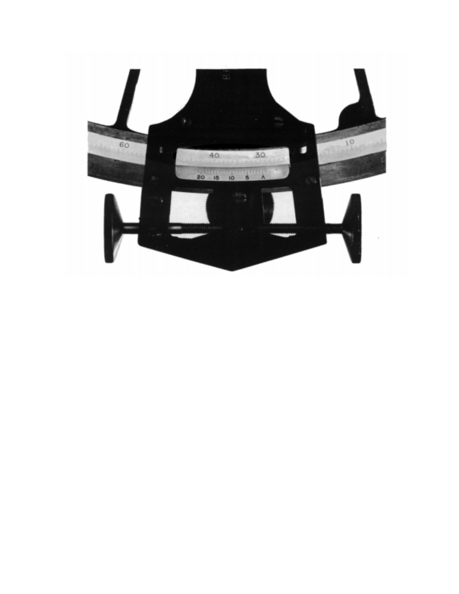
The principle of reading a vernier sextant is the same, but
the reading is made in two steps. Figure 1608b shows a typical
altitude setting. Each degree on the arc of this sextant is grad-
uated into three parts, permitting an initial reading by the
reference mark on the index arm to the nearest 20' of arc. In this
illustration the reference mark lies between 29
°
40' and 30
°
00',
indicating a reading between these values. The reading for the
fraction of 20' is made using the vernier, which is engraved on
the index arm and has the small reference mark as its zero
graduation. On this vernier, 40 graduations coincide with 39
graduations on the arc. Each graduation on the vernier is equiv-
alent to 1/40 of one graduation of 20' on the arc, or 0.5', or 30".
In the illustration, the vernier graduation representing 2 1/2'
(2'30") most nearly coincides with one of the graduations on
the arc. Therefore, the reading is 29
°
42'30", or 29
°
42.5', as be-
fore. When a vernier of this type is used, any doubt as to which
mark on the vernier coincides with a graduation on the arc can
usually be resolved by noting the position of the vernier mark
on each side of the one that seems to be in coincidence.
Negative readings, such as a negative index correction,
are made in the same manner as positive readings; the var-
ious figures are added algebraically. Thus, if the three parts
of a micrometer drum reading are ( - )1
°
, 56' and 0.3', the
total reading is ( - )1
°
+ 56' + 0.3' = ( - )3.7'.
1609. Developing Observational Skill
A well-constructed marine sextant is capable of measur-
ing angles with an instrument error not exceeding 0.1'. Lines
of position from altitudes of this accuracy would not be in er-
ror by more than about 200 yards. However, there are various
sources of error, other than instrumental, in altitudes mea-
sured by sextant. One of the principal sources is the observer.
The first fix a student celestial navigator plots is likely
to be disappointing. Most navigators require a great amount
of practice to develop the skill necessary for good observa-
Figure 1608b. Vernier sextant set at 29
°
42'30".

278
INSTRUMENTS FOR CELESTIAL NAVIGATION
tions. But practice alone is not sufficient. Good technique
should be developed early and refined throughout the navi-
gator’s career. Many good pointers can be obtained from
experienced navigators, but each develops his own tech-
nique, and a practice that proves successful for one observer
may not help another. Also, an experienced navigator is not
necessarily a good observer. Navigators have a natural ten-
dency to judge the accuracy of their observations by the size
of the figure formed when the lines of position are plotted.
Although this is some indication, it is an imperfect one, be-
cause it does not indicate errors of individual observations,
and may not reflect constant errors. Also, it is a compound
of a number of errors, some of which are not subject to the
navigator’s control.
Lines of position from celestial observations can be
compared with good positions obtained by electronics or pi-
loting. Common sources of error are:
1. The sextant may not be rocked properly.
2. Tangency may not be judged accurately.
3. A false horizon may have been used.
4. Subnormal refraction (dip) might be present.
5. The height of eye may be wrong.
6. Time might be in error.
7. The index correction may have been determined
incorrectly.
8. The sextant might be out of adjustment.
9. An error may have been made in the computation.
Generally, it is possible to correct observation tech-
nique errors, but occasionally a personal error will persist.
This error might vary as a function of the body observed,
degree of fatigue of the observer, and other factors. For this
reason, a personal error should be applied with caution.
To obtain greater accuracy, take a number of closely-
spaced observations. Plot the resulting altitudes versus time
and fair a curve through the points. Unless the body is near
the celestial meridian, this curve should be a straight line.
Use this graph to determine the altitude of the body at any
time covered by the graph. It is best to use a point near the
middle of the line. Using a calculator to reduce the sight
will also yield greater accuracy because of the rounding er-
rors inherent in the use of sight reduction tables.
A simpler method involves making observations at
equal intervals. This procedure is based upon the assump-
tion that, unless the body is on the celestial meridian, the
change in altitude should be equal for equal intervals of
time. Observations can be made at equal intervals of alti-
tude or time. If time intervals are constant, the mid time and
the average altitude are used as the observation. If altitude
increments are constant, the average time and mid altitude
are used.
If only a small number of observations is available, re-
duce and plot the resulting lines of position; then adjust
them to a common time. The average position of the line
might be used, but it is generally better practice to use the
middle line. Reject any observation considered unreliable
when determining the average.
1610. Care Of The Sextant
A sextant is a rugged instrument. However, careless
handling or neglect can cause it irreparable harm. If you
drop it, take it to an instrument repair shop for testing and
inspection. When not using the sextant, stow it in a sturdy
and sufficiently padded case. Keep the sextant out of exces-
sive heat and dampness. Do not expose it to excessive
vibration. Do not leave it unattended when it is out of its
case. Do not hold it by its limb, index arm, or telescope.
Liftit by its frame or handle. Do not lift it by its arc or index
bar.
Next to careless handling, moisture is the sextant’s
greatest enemy. Wipe the mirrors and the arc after each use.
If the mirrors get dirty, clean them with lens paper and a
small amount of alcohol. Clean the arc with ammonia; nev-
er use a polishing compound. When cleaning, do not apply
excessive pressure to any part of the instrument.
Silica gel kept in the sextant case will help keep the in-
strument free from moisture and preserve the mirrors.
Occasionally heat the silica gel to remove the absorbed
moisture.
Rinse the sextant with fresh water if sea water gets on
it. Wipe the sextant gently with a soft cotton cloth and dry
the optics with lens paper.
Glass optics do not transmit all the light received be-
cause glass surfaces reflect a small portion of light incident
on their face. This loss of light reduces the brightness of the
object viewed. Viewing an object through several glass op-
tics affects the perceived brightness and makes the image
indistinct. The reflection also causes glare which obscures
the object being viewed. To reduce this effect to a mini-
mum, the glass optics are treated with a thin, fragile, anti-
reflection coating. Therefore, apply only light pressure
when polishing the coated optics. Blow loose dust off the
lens before wiping them so grit does not scratch the lens.
Frequently oil and clean the tangent screw and the teeth
on the side of the limb. Use the oil provided with the sextant
or an all-purpose light machine oil. Occasionally set the in-
dex arm of an endless tangent screw at one extremity of the
limb, oil it lightly, and then rotate the tangent screw over
the length of the arc. This will clean the teeth and spread oil
over them. When stowing a sextant for a long period, clean
it thoroughly, polish and oil it, and protect its arc with a thin
coat of petroleum jelly.
If the mirrors need re-silvering, take the sextant to an
instrument shop.
1611. Non Adjustable Sextant Errors
The non-adjustable sextant errors are prismatic error,
graduation error, and centering error.
Prismatic error occurs when the faces of the shade
INSTRUMENTS FOR CELESTIAL NAVIGATION
279
glasses and mirrors are not parallel. Error due to lack of par-
allelism in the shade glasses may be called shade error.
The navigator can determine shade error in the shade glass-
es near the index mirror by comparing an angle measured
when a shade glass is in the line of sight with the same angle
measured when the glass is not in the line of sight. In this
manner, determine and record the error for each shade
glass. Before using a combination of shade glasses, deter-
mine their combined error. If certain observations require
additional shading, use the colored telescope eyepiece cov-
er. This does not introduce an error because direct and
reflected rays are traveling together when they reach the
cover and are, therefore, affected equally by any lack of
parallelism of its two sides.
Graduation errors occur in the arc, micrometer drum,
and vernier of a sextant which is improperly cut or incor-
rectly calibrated. Normally, the navigator cannot determine
whether the arc of a sextant is improperly cut, but the prin-
ciple of the vernier makes it possible to determine the
existence of graduation errors in the micrometer drum or
vernier. This is a useful guide in detecting a poorly made in-
strument. The first and last markings on any vernier should
align perfectly with one less graduation on the adjacent mi-
crometer drum.
Centering error results if the index arm does not pivot
at the exact center of the arc’s curvature. Calculate center-
ing error by measuring known angles after removing all
adjustable errors. Use horizontal angles accurately mea-
sured with a theodolite as references for this procedure.
Several readings by both theodolite and sextant should min-
imize errors. If a theodolite is not available, use calculated
angles between the lines of sight to stars as the reference,
comparing these calculated values with the values deter-
mined by the sextant. To minimize refraction errors, select
stars at about the same altitude and avoid stars near the ho-
rizon. The same shade glasses, if any, used for determining
index error should be used for measuring centering error.
The manufacturer normally determines the magnitude
of all three non-adjustable errors and reports them to the
user as instrument error. The navigator should apply the
correction for this error to each sextant reading.
1612. Adjustable Sextant Error
The navigator should measure and remove the follow-
ing adjustable sextant errors in the order listed:
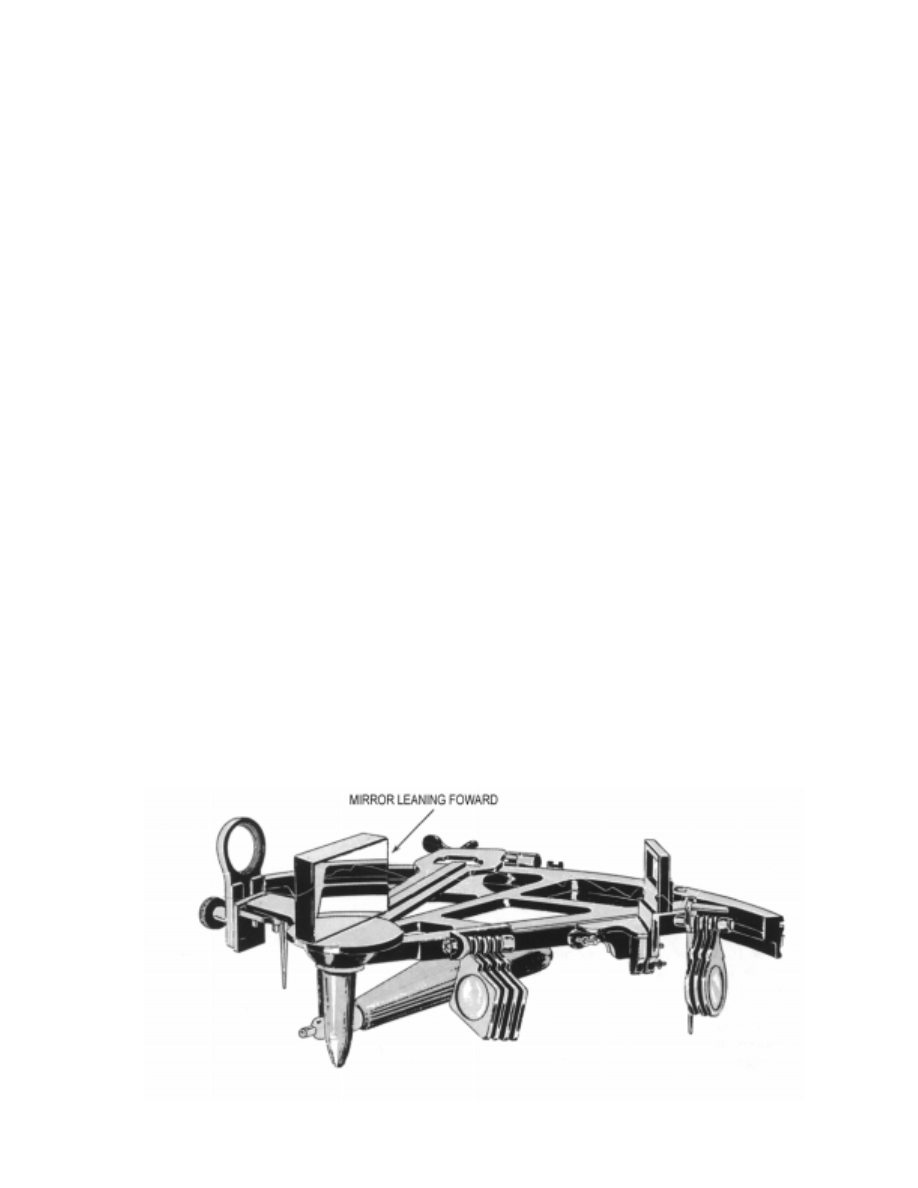
1. Perpendicularity Error: Adjust first for perpendicu-
larity of the index mirror to the frame of the sextant. To test for
perpendicularity, place the index arm at about 35
°
on the arc
and hold the sextant on its side with the index mirror up and to-
ward the eye. Observe the direct and reflected views of the
sextant arc, as illustrated in Figure 1612a. If the two views are
not joined in a straight line, the index mirror is not perpendic-
ular. If the reflected image is above the direct view, the mirror
is inclined forward. If the reflected image is below the direct
view, the mirror is inclined backward. Make the adjustment
using two screws behind the index mirror.
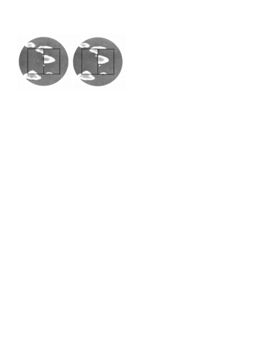
2. Side Error: An error resulting from the horizon glass
not being perpendicular is called side error. To test for side er-
ror, set the index arm at zero and direct the line of sight at a star.
Then rotate the tangent screw back and forth so that the reflected
image passes alternately above and below the direct view. If, in
changing from one position to the other, the reflected image
passes directly over the unreflected image, no side error exists.
If it passes to one side, side error exists. Figure 1612b illustrates
observations without side error (left) and with side error (right).
Whether the sextant reads zero when the true and reflected im-
ages are in coincidence is immaterial for this test. An alternative
method is to observe a vertical line, such as one edge of the mast
of another vessel (or the sextant can be held on its side and the
horizon used). If the direct and reflected portions do not form a
continuous line, the horizon glass is not perpendicular to the
Figure 1612a. Testing the perpendicularity of the index mirror. Here the mirror is not perpendicular.
280
INSTRUMENTS FOR CELESTIAL NAVIGATION
frame of the sextant. A third method involves holding the sex-
tant vertically, as in observing the altitude of a celestial body.
Bring the reflected image of the horizon into coincidence with
the direct view until it appears as a continuous line across the ho-
rizon glass. Then tilt the sextant right or left. If the horizon still
appears continuous, the horizon glass is perpendicular to the
frame, but if the reflected portion appears above or below the
part seen directly, the glass is not perpendicular. Make the ap-
propriate adjustment using two screws behind the horizon glass.
3. Collimation Error: If the line of sight through the
telescope is not parallel to the plane of the instrument, a col-
limation error will result. Altitudes measured will be
greater than their actual values. To check for parallelism of
the telescope, insert it in its collar and observe two stars 90
°
or more apart. Bring the reflected image of one into coinci-
dence with the direct view of the other near either the right
or left edge of the field of view (the upper or lower edge if
the sextant is horizontal). Then tilt the sextant so that the
stars appear near the opposite edge. If they remain in coin-
cidence, the telescope is parallel to the frame; if they
separate, it is not. An alternative method involves placing
the telescope in its collar and then laying the sextant on a
flat table. Sight along the frame of the sextant and have an
assistant place a mark on the opposite bulkhead, in line with
the frame. Place another mark above the first, at a distance
equal to the distance from the center of the telescope to the
frame. This second line should be in the center of the field
of view of the telescope if the telescope is parallel to the
frame. Adjust the collar to correct for non-parallelism.
4. Index Error: Index error is the error remaining after
the navigator has removed perpendicularity error, side error,
and collimation error. The index mirror and horizon glass not
being parallel when the index arm is set exactly at zero is the
major cause of index error. To test for parallelism of the mir-
rors, set the instrument at zero and direct the line of sight at the
horizon. Adjust the sextant reading as necessary to cause both
images of the horizon to come into line. The sextant’s reading
when the horizon comes into line is the index error. If the index
error is positive, subtract it from each sextant reading. If the in-
dex error is negative, add it to each sextant reading.
1613. Selecting A Sextant
Carefully match the selected sextant to its required uses.
For occasional small craft or student use, a plastic sextant may
be adequate. A plastic sextant may also be appropriate for an
emergency navigation kit. Accurate offshore navigation re-
quires a quality metal instrument. For ordinary use in
measuring altitudes of celestial bodies, an arc of 90
°
or slightly
more is sufficient. If using a sextant for back sights or deter-
mining horizontal angles, purchase one with a longer arc. If
necessary, have an experienced mariner examine the sextant
and test it for non adjustable errors before purchase.
1614. The Artificial Horizon
Measurement of altitude requires an exact horizontal ref-
erence. At sea, the visible sea horizon normally provides this
reference. If the horizon is not clearly visible, however, a dif-
ferent horizontal reference is required. Such a reference is
commonly termed an artificial horizon. If it is attached to, or
part of, the sextant, altitudes can be measured at sea, on land,
or in the air, whenever celestial bodies are available for obser-
vations. Any horizontal reflecting surface will work. A pan of
any liquid sheltered from the wind will serve. Foreign material
on the surface of the liquid is likely to distort the image and in-
troduce an error in the reading.
To use an external artificial horizon, stand or sit in such
a position that the celestial body to be observed is reflected
in the liquid, and is also visible in direct view. With the sex-
tant, bring the double-reflected image into coincidence with
the image appearing in the liquid. For a lower limb obser-
vation of the sun or the moon, bring the bottom of the
double-reflected image into coincidence with the top of the
image in the liquid. For an upper-limb observation, bring
the opposite sides into coincidence. If one image covers the
other, the observation is of the center of the body.
After the observation, apply the index correction and any
other instrumental correction. Then take half the remaining an-
gle and apply all other corrections except dip (height of eye)
correction, since this is not applicable. If the center of the sun
or moon is observed, omit the correction for semidiameter.
1615. Artificial Horizon Sextants
Various types of artificial horizons have been used, in-
cluding a bubble, gyroscope, and pendulum. Of these, the
bubble has been most widely used. This type of instrument is
fitted as a backup system to inertial and other positioning sys-
tems in a few aircraft, fulfilling the requirement for a self-
contained, non-emitting system. On land, a skilled observer
using a 2-minute averaging bubble or pendulum sextant can
Figure 1612b. Testing the perpendicularity of the horizon glass.
On the left, side error does not exist. At the right, side error does
exist.

INSTRUMENTS FOR CELESTIAL NAVIGATION
281
measure altitudes to an accuracy of perhaps 2’, (2 miles).
This, of course, refers to the accuracy of measurement only,
and does not include additional errors such as abnormal re-
fraction, deflection of the vertical, computing and plotting
errors, etc. In steady flight through smooth air the error of a
2-minute observation is increased to perhaps 5 to 10 miles.
At sea, with virtually no roll or pitch, results should ap-
proach those on land. However, even a gentle roll causes
large errors. Under these conditions observational errors of
10-16 miles are not unreasonable. With a moderate sea, er-
rors of 30 miles or more are common. In a heavy sea, any
useful observations are virtually impossible to obtain. Sin-
gle altitude observations in a moderate sea can be in error
by a matter of degrees.
When the horizon is obscured by ice or haze, polar nav-
igators can sometimes obtain better results with an artificial-
horizon sextant than with a marine sextant. Some artificial-
horizon sextants have provision for making observations
with the natural horizon as a reference, but results are not
generally as satisfactory as by marine sextant. Because of
their more complicated optical systems, and the need for pro-
viding a horizontal reference, artificial-horizon sextants are
generally much more costly to manufacture than marine
sextants.
Altitudes observed by artificial-horizon sextants are
subject to the same errors as those observed by marine sex-
tant, except that the dip (height of eye) correction does not
apply. Also, when the center of the sun or moon is ob-
served, no correction for semidiameter is required.
CHRONOMETERS
1616. The Marine Chronometer
The spring-driven marine chronometer is a precision
timepiece. It is used aboard ship to provide accurate time
for timing celestial observations. A chronometer differs
from a spring-driven watch principally in that it contains a
variable lever device to maintain even pressure on the
mainspring, and a special balance designed to compensate
for temperature variations.
A spring-driven chronometer is set approximately to
Greenwich mean time (GMT) and is not reset until the in-
strument is overhauled and cleaned, usually at three-year
intervals. The difference between GMT and chronometer
time (C) is carefully determined and applied as a correction
to all chronometer readings. This difference, called chro-
nometer error (CE), is fast (F) if chronometer time is later
than GMT, and slow (S) if earlier. The amount by which
chronometer error changes in 1 day is called chronometer
rate. An erratic rate indicates a defective instrument requir-
ing repair.
The principal maintenance requirement is regular
winding at about the same time each day. At maximum in-
tervals of about three years, a spring-driven chronometer
should be sent to a chronometer repair shop for cleaning
and overhaul.
1617. Quartz Crystal Marine Chronometers
Quartz crystal marine chronometers have replaced
spring-driven chronometers aboard many ships because of
their greater accuracy. They are maintained on GMT directly
from radio time signals. This eliminates chronometer error
(CE) and watch error (WE) corrections. Should the second
hand be in error by a readable amount, it can be reset
electrically.
The basic element for time generation is a quartz crys-
tal oscillator. The quartz crystal is temperature
compensated and is hermetically sealed in an evacuated en-
velope. A calibrated adjustment capability is provided to
adjust for the aging of the crystal.
The chronometer is designed to operate for a minimum
of 1 year on a single set of batteries. A good marine chro-
nometer has a built-in push button battery test meter. The
meter face is marked to indicate when the battery should be
replaced. The chronometer continues to operate and keep
the correct time for at least 5 minutes while the batteries are
changed. The chronometer is designed to accommodate the
gradual voltage drop during the life of the batteries while
maintaining accuracy requirements.
1618. Watches
A chronometer should not be removed from its case to
time sights. Observations may be timed and ship’s clocks
set with a comparing watch, which is set to chronometer
time (GMT) and taken to the bridge wing for recording
sight times. In practice, a wrist watch coordinated to the
nearest second with the chronometer will be adequate.
A stop watch, either spring wound or digital, may also
be used for celestial observations. In this case, the watch is
started at a known GMT by chronometer, and the elapsed
time of each sight added to this to obtain GMT of the sight.

Document Outline
- Chapter 16
- Instruments for Celestial Navigation
- The Marine Sextant
- 1600 . Description And Use
- 1601 . Optical Principles Of A Sextant
- 1602 . Micrometer Drum Sextant
- 1603 . Vernier Sextant
- 1604 . Sextant Sun Sights
- 1605 . Sextant Moon Sights
- 1606 . Sextant Star And Planet Sights
- 1607 . Taking A Sight
- 1608 . Reading The Sextant
- 1609 . Developing Observational Skill
- 1610 . Care Of The Sextant
- 1611 . Non Adjustable Sextant Errors
- 1612 . Adjustable Sextant Error
- 1613 . Selecting A Sextant
- 1614 . The Artificial Horizon
- 1615 . Artificial Horizon Sextants
- Chronometers
- The Marine Sextant
- Instruments for Celestial Navigation
Wyszukiwarka
Podobne podstrony:
Celestron CGE
CelestynaV
CHAPT14 IBS
Chapt14
Chapt12
Celestron NexStar SLT
Chapt18[1]
Chapt15[1]
CelestynaI
Celestial Navigation
CHAPT11 sat nav
CelestynaIII
Celestron C6, C8, C9 25, C11 SGT
Chapt15
Celestynka Clasic
CHAPT12 hyperbolic
Celestius Ex Ex Inhereditare
Znani pedagodzy, 8. Celestyn Freinet
Metody, Metody, formy i techniki Celestyna Freineta
więcej podobnych podstron