CL 75A 24V
User´s guide
Bedienerhandbuch
mit Montageanleitung
Code Nr. 99 97 0853
M 853 GB + D
Nr.: 603691
Versionsnr.: 1.0
Big Dutchman International GmbH . Calveslage . Auf der Lage 2 . 49377 Vechta
04447/801-0 . Fax 04447/801-237

CL 75A 24V Winch motors
Page 2
User´s guide CL 75A 24V
Edition: 27.05.98
ν
M 853 GB
1. PRODUCT DESCRIPTION ............................................................................................................................................ 3
Fig. 1 Operation............................................................................................................................................................ 3
2. MAINTENANCE ............................................................................................................................................................. 3
3. ELECTRIC INSTALLATION ........................................................................................................................................ 3
3.1 N
ORMAL
C
ONTINUOUSLY
V
ARIABLE
F
UNCTION
............................................................................................................. 4
Fig. 2 “Stepless” block diagram and connection ........................................................................................................... 4
3.2 ON/OFF E
MERGENCY
O
PENING
F
UNCTION
................................................................................................................... 5
Fig. 3 “ON/OFF-Emergency opening” block diagram and connection .......................................................................... 5
4. ASSEMBLY ..................................................................................................................................................................... 6
5. TROUBLE SHOOTING AND EMERGENCY OPERATION ...................................................................................... 8
Fig. 5 Motorprint and Noise Capacitor .......................................................................................................................... 8
Fig. 6 Mounting of Switch Wire................................................................................................................................... 9
6. SPARE PARTS AND ACCESSORIES.......................................................................................................................... 10
7. TECHNICAL DATA...................................................................................................................................................... 10

CL 75A 24V Winch motors
Page 3
User´s guide CL 75A 24V
Edition: 27.05.98
ν
M 853 GB
1. Product Description
CL 75A is a winch motor designed to control shutters and inlets, e.g. in livestock ventilation systems. CL 75A
has 2 wires which permit independent adjustment of pulling length and pulling direction. CL 75A is equipped
with a feedback potentiometer for position indication.
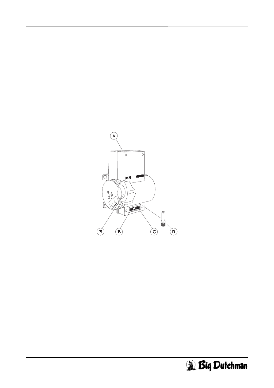
There is a switch to select between AUT and MAN (B). The winch motor is relay controlled and can be infi-
nitely variable controlled between open and closed position. In the automatic position the motor is controlled by
the climate computer, e.g. MC 34H. In the manual position the motor can be opened manually, stopped or
closed with the switch (C). CL 75A has built-in limit switches and a thermal contact to switch off the motor if it
gets too hot. Under emergency conditions CL 75A can be operated by means of emergency opening crank, item
No. 432020, or a battery-operated drilling machine and enclosed coupling piece (D) through the hole (A).
CL 75A for 24V is designed particularly for systems with emergency opening, where the energy reserve is
a 24V battery.
Also possible is ON/OFF-emergency opening, e.g. the winch motor opens a window completely.
Fig. 1 Operation
2. Maintenance
Check regularly that the wires are O.K. and not worn in the wire tracks.
The motor carbon has a life of approx. 5,000 operating hours, corresponding to approx. 10 years of nor-
mal operation. If required a new carbon brush can be ordered with SKOV, see section 6 “Spare Parts and
Accessories”.
3. Electric Installation
CL 75A is connected to the automatic unit by a seven-core cable (Fig. 2) or five-core cable (Fig. 3).
After installation set the switch (B) to MAN, and run the motor from stop to stop via the switch (C) in
order to make sure that the mechanical coupling is O.K. Set the switch (B) to AUT and check that the
motor is able to open, stop and close via the automatic unit. The opening and closing directions are labeled
on the wire wheel.
CL 75A 24V Winch motors
Page 4
User´s guide CL 75A 24V
Edition: 27.05.98
ν
M 853 GB
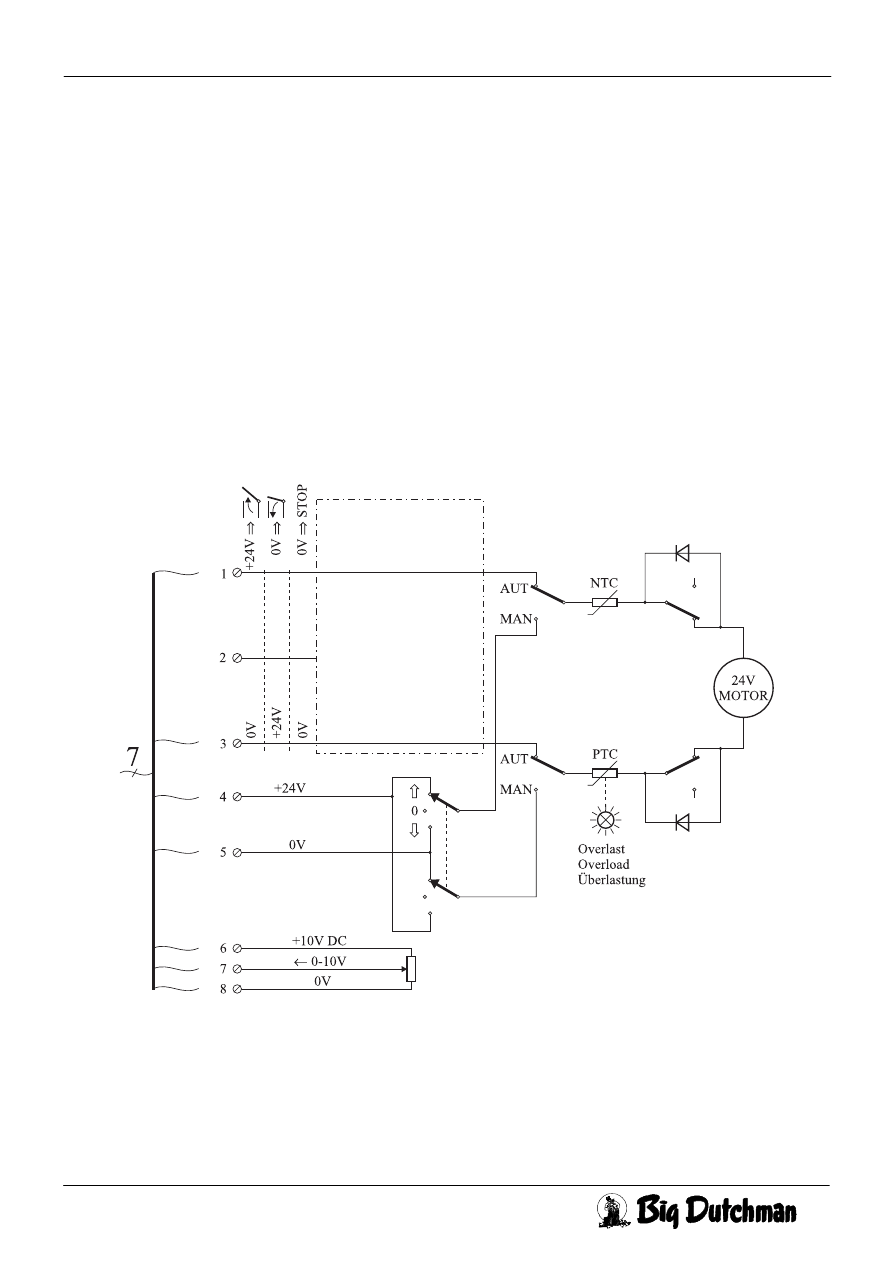
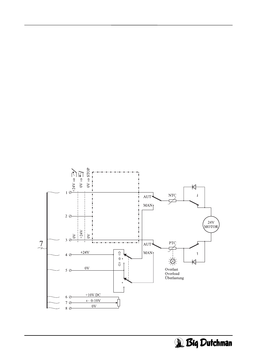
3.1 Normal Continuously Variable Function
Set the AUT./MAN. - switch (B) at AUT. The motor will be controlled on cable 1 and 3.
If the CL 75A is supplied with 24V DC on the wires 1(= +24V) and 3(= 0V) the motor will open. Re-
versed polarity closes the motor. Wire no. 2 is not used when operated continuously variable.
Equal polarity on wire 1 and 3 causes a stop. If wire no. 1, wire no. 3 or both are switched off, the motor
will stop. Wire no. 4 (= +24V DC) and 5(= 0V) must always be connected constantly so that the motor
can open/close manually with the switches (B) and (C).
To the potentiometer is connected for example 10V DC to wire no. 6 (= +10V) and wire no. 8 (= 0V).
Wire no. 7 will then have 0V when motor is closed, approx. 5V when motor is half open and approx. 10V
when motor is fully opened.
When operating automatically, set the switch (B) at position AUT.
In case of power failure the motor can be adjusted by means of the enclosed coupling (D) and emergency
opening crank or a drilling machine, preferably battery operated. The plug (A) is also screwed off with the
coupling.
Fig. 2 “Stepless” block diagram and connection
CL 75A 24V Winch motors
Page 5
User´s guide CL 75A 24V
Edition: 27.05.98
ν
M 853 GB
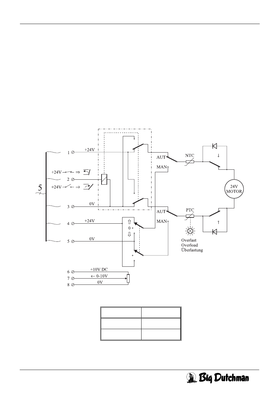
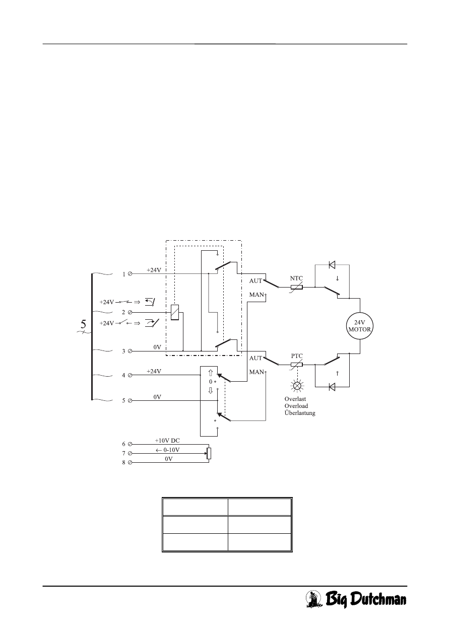
3.2 ON/OFF Emergency Opening Function
Set the AUT./MAN. switch (B) at AUT.
This function is used for emergency opening of a window in a house with “diffuse” air outlet. As an exam-
ple the motor may be controlled by a DOL 2012 thermostat or a mechanical Danfoss thermostat + MC
78M emergency opening unit.
The motor is controlled ON/OFF (open/close on wire 2 with only one single relay make contact). When
the temperature gets too high, the relay switch of the thermostat should switch off +24V for wire 2 and the
motor opens fully.
As long as wire 2 has +24V the motor is kept completely closed.
Wire 1(=+24V) and 3(=0V) must always be connected in this application.
Wire 4(= +24V DC) and 5(= 0V) must always be connected to enable the motor to open and close manu-
ally with the switches (B) and (C).
Fig. 3 “ON/OFF-Emergency opening” block diagram and connection
Cable length Cross section
0 →
30 m 1.5 mm²
20
→
50 m 2.5 mm²
Conductor cross section
CL 75A 24V Winch motors
Page 6
User´s guide CL 75A 24V
Edition: 27.05.98
ν
M 853 GB
4. Assembly
CL 75A is delivered with 2 wires discs and corresponding wire. If only one wire is to be used, dismount the ut-
termost. In order to use the same bolts again, mount the wire discs again.
If 3 wires should be used, an extra wire disc with wire, item No. 432925, can be re-mounted. The same bolts can
be used.
CL 75A should be mounted vertically or horizontally on the wall. At horizontal mounting the shaft should turn
down in order to avoid water penetration. In countries with a hot climate it should be avoided that the sun shines
directly on CL 75A. 3 or 4 pcs. of 10 mm through-bolts should be used to secure the unit. Above the unit, (A)
on Fig. 1, sufficient space should be left free for an emergency opening crank or a battery-operated drilling ma-
chine to operate the motor, should emergency opening be required. The wires can be led in any direction, also
through the wall. The wires should be wound on to the wire wheel in order to obtain the correct pulling or
slacking length.
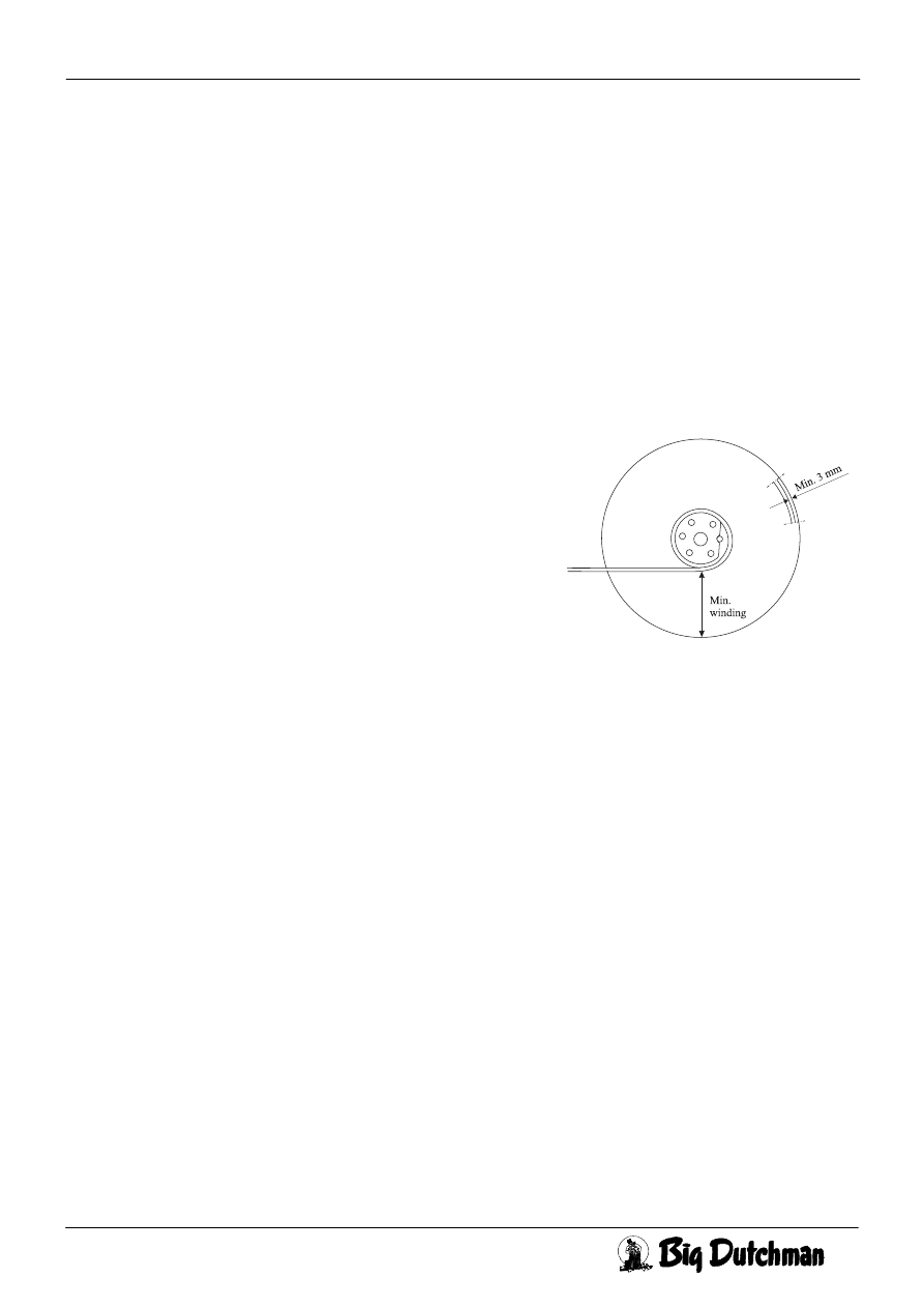
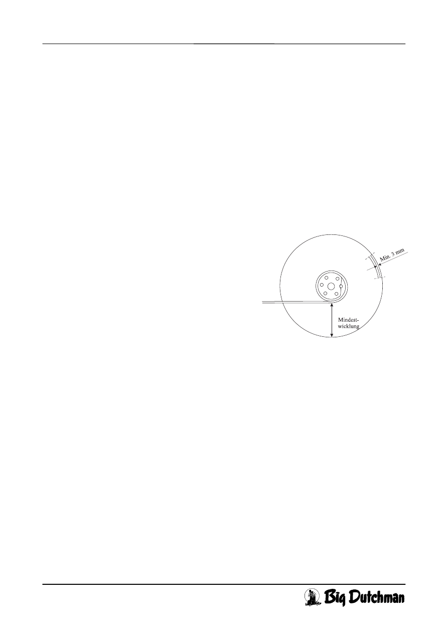
When you are going to wind a winch motor, it should always be in
the fully closed position. Fig. 4 shows where to measure to get rough
values in the scheme. Please note that min. 3 mm should be free to
the outer periphery and the hub should always be “covered” by a
wire winding as shown in the figure. The figure also shows the defi-
nition of “number of wire windings = 1”.
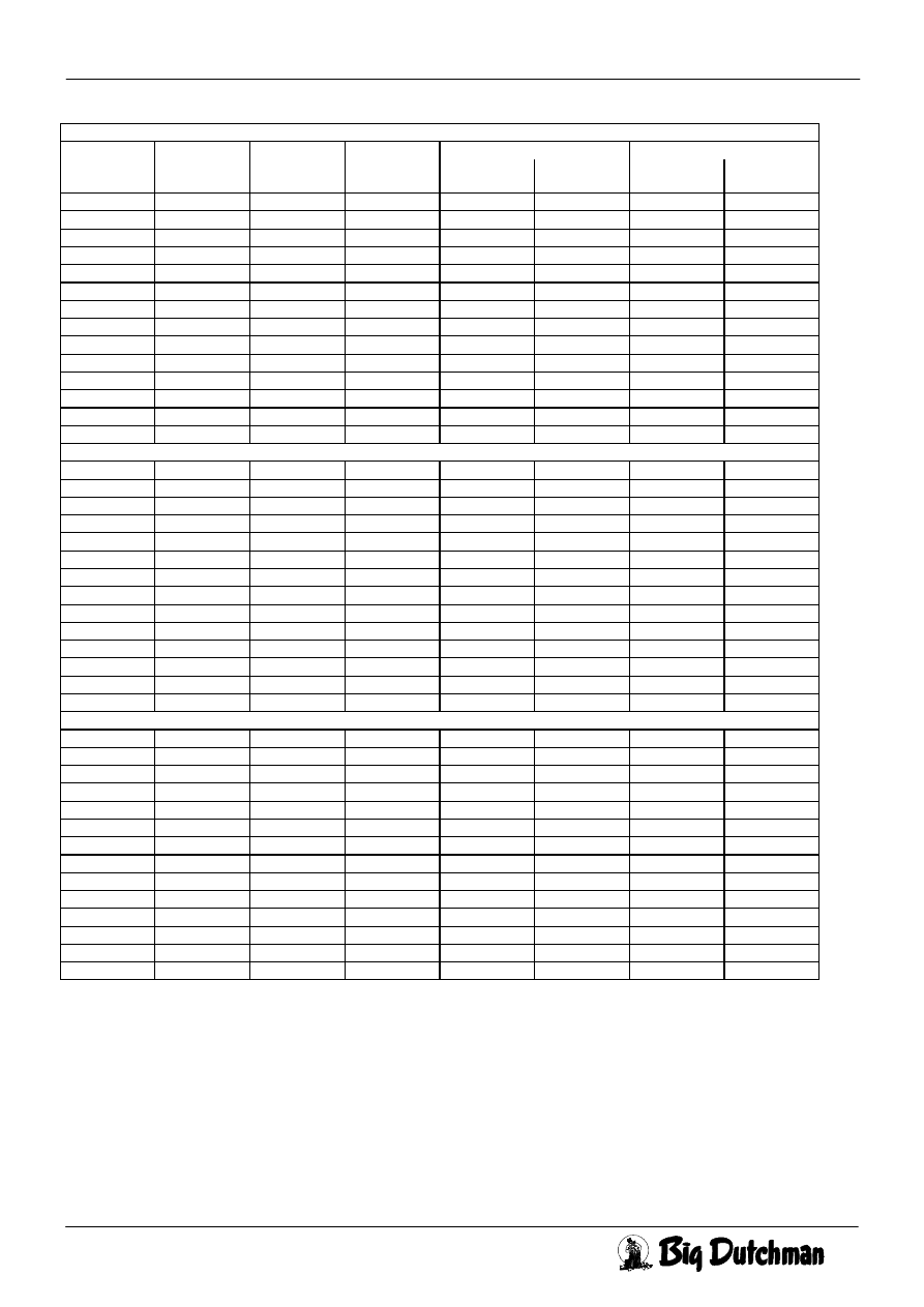
Following table shows the rough relation between load, the number
of wire windings and the pulling or slacking lengths.
1000 N equal 98 kg.
Fig. 4
CL 75A 24V Winch motors
Page 7
User´s guide CL 75A 24V
Edition: 07.09.98
ν
M 853 GB
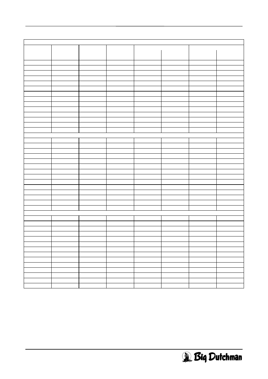
CL 75A-1
Measure to One-way pull Balanced
No. of wire
windings
Pulling length
[mm]
Slacking leng.
[mm]
periphery
before pull/sla.
Tractive force
[N]
Moment
[Nm]
Tractive force
[N]
Moment
[Nm]
1 237 - 48 1794 56 2384 75
2 260 232 45 1748 60 2170 75
3 284 256 42 1702 64 1992 75
4 307 279 39 1656 68 1840 75
5 331 303 36 1610 71 1710 75
6 354 326 33 1564 74 1597 75
7 377 349 30 1498 75 1498 75
8 401 373 27 1411 75 1411 75
9 424 396 24 1379 75 1333 75
10 447 419 21 1333 75 1263 75
11 471 443 17 1263 75 1201 75
12 494 466 14 1201 75 1144 75
13 517 489 11 1144 75 1092 75
14 541 - 8 1092 75 1045 75
CL 75A-3
1 502 - 48 1767 59 2251 75
2 549 - 45 1721 63 2059 75
3 596 484 42 1674 66 1898 75
4 642 530 39 1628 69 1760 75
5 689 577 36 1582 72 1640 75
6 736 624 33 1536 75 1536 75
7 783 670 30 1445 75 1445 75
8 829 717 27 1379 75 1363 75
9 876 764 24 1363 75 1290 75
10 923 811 21 1290 75 1225 75
11 969 857 17 1225 75 1166 75
12 1016 904 14 1166 75 1112 75
13 1063 951 11 1112 75 1064 75
14 - - 8 1064 75 1019 75
CL 75A-6
1 1117 - 48 1711 64 2025 75
2 1210 - 45 1665 67 1868 75
3 1303 - 42 1619 70 1735 75
4 1397 - 39 1573 73 1618 75
5 1490 - 36 1517 75 1517 75
6 1584 1135 33 1427 75 1427 75
7 1677 1229 30 1379 75 1348 75
8 1771 1322 27 1348 75 1277 75
9 1864 1416 24 1277 75 1213 75
10 1958 1509 21 1213 75 1155 75
11 2051 1603 17 1155 75 1102 75
12 - 1696 14 1102 75 1054 75
13 - 1789 11 1054 75 1010 75
14 - - 8 1010 75 970 75
CL 75A 24V Winch motors
Page 8
User´s guide CL 75A 24V
Edition: 27.05.98
ν
M 853 GB
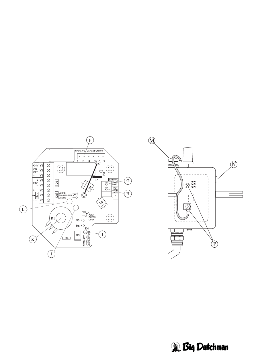
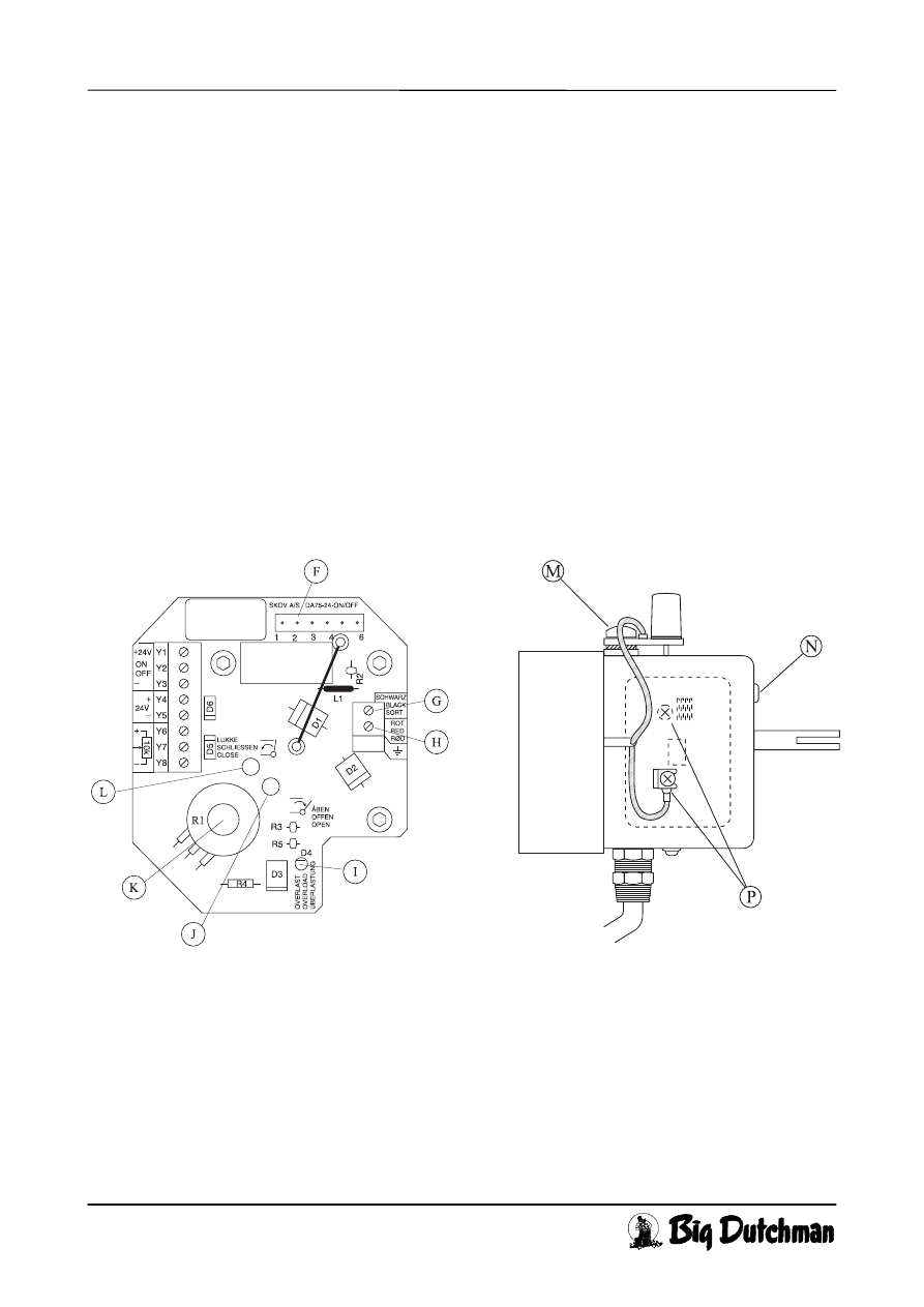
5. Trouble Shooting and Emergency Operation
During normal operation it is O.K. that the R2 of the motorprint gets hot.
If the motor will not run, set the switch (B) at MAN and try to operate the motor via switch (C). If suc-
cessful, check the control signal connection to the automatic unit and the feed back signal from the poten-
tiometer, if necessary.
If not successful, check that 24V ac is being supplied. (If the valves are fully open, close down instead).
If so, set the switch (C) to open position (upwards), remove the cover. Check whether the plug (F) has
been connected. Measure the voltage to the motor between terminal (G) and (H), (motorprint). If the volt-
age is O.K. and the motor does not run, check the carbon (P). If this does not help, replace the motor. If
no voltage, check whether the overload lamp (I) is red. If (I) is on, the motor is overloaded (too many in-
lets, wire misadjusted). Remove the overload, set (B) to MAN and (C) to 0 (centre position) for 10 sec-
onds, enabling the overload relay to cool. Set (C) to (upwards) or (downwards), if no voltage, replace the
circuit board.
Fig. 5 Motorprint and Noise Capacitor
Replacement of the circuit board:
Remove the motor wires (G) and (H). Remove the plug (F) to the switch. Loosen the 3 bolts by means of
the enclosed Allen key and pull out the circuit board. Adjust the potentiometer shaft (P) on the new circuit
board to fit into the hole of the large gear-wheel. Remount the circuit board. If the motor is in a position
where it is being activated by the limit switch, it is necessary to help the arms of the limit switch contacts
(J) and (L) on to the cam of the gear-wheel. Tighten the bolts and remount wires and plug. Test the motor
as mentioned under Installation.
CL 75A 24V Winch motors
Page 9
User´s guide CL 75A 24V
Edition: 27.05.98
ν
M 853 GB
Replacement of the gear motor:
Relieve the wires and loosen the screw (E) Fig. 1. Now the complete wire wheel can be removed from the
shaft. Take care that the wires do not come off the wire tracks and that the slot (piece of metal) does not
fall out of the groove of the shaft. Take out the circuit board, see above. Remove the 4 bolts by which the
gear is secured to the housing. If the new motor is not provided with noise capacitor (M), transfer the
noise capacitor (M) from the defective to the new motor, before mounting it. Demount the the motor lid
with the screw (N). Loosen the screws (P) and pull out the two wires. Mount the noise capacitor (M) on
the new motor. Mount the new motor in reverse order. Prior to remounting the wire wheel, set the key-
way of the shaft to its previous position (as for CL 75A-3 the shaft should also be adjusted to the correct
turn, compare with the plastic gear wheels on the opposite side).
Test the motor as mentioned under Installation.
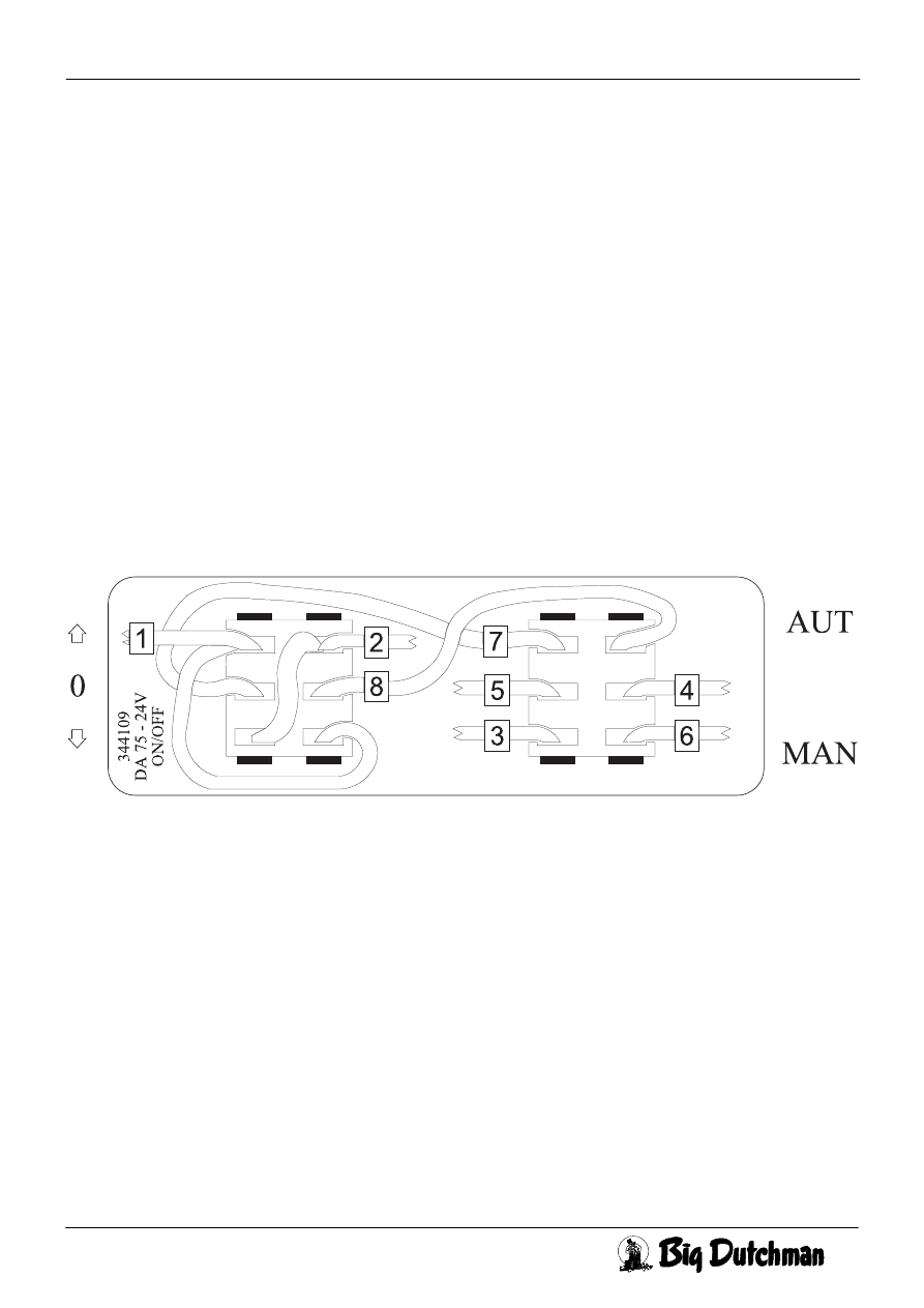
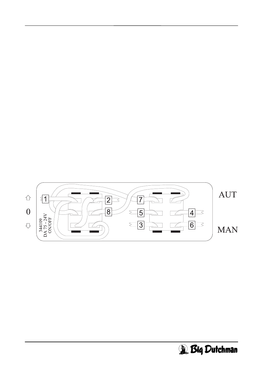
Replacement of the switches:
A spare unit includes 2 switches and a set of wires. Remove the relief fitting in the cover, pull out the wires
of the switches and press the switches out of the cover by squeezing the barbs together. Mount the new
switches, please do not forget that the 3-position switch should be placed to the right (front view). Con-
nect the wires, see Fig. 6. Mount the switch wires as depicted on the inside of the cover. Test the motor as
mentioned under Installation.
Fig. 6 Mounting of Switch Wire
Emergency operation:
In case of a total breakdown the system can be operated manually. Unscrew the bung at (A) Fig. 1. Mount
the coupling (D) on an emergency opening crank or a drilling machine, preferably battery operated. Lead
in the coupling through the hole at (A) until it engages with the motor shaft. If the shaft is turned clock-
wise, the gear motor opens the system. Do not open or close too much as the mechanical installation may
be damaged.
CL 75A 24V Winch motors
Page10
User´s guide CL 75A 24V
Edition: 07.09.98
ν
M 853 GB
6. Spare Parts and Accessories
The following parts can be ordered from SKOV:
Spare parts 432904 CL 75A-1 gearmotor 24 V
432908 CL 75-3/75A-3 gearmotor 24 V
432919 CL 75A-6 gearmotor 24V
432910 CL 75/75A-24 V motor carbon
432953 CL 75/75A-24V circuit board
432924 CL 75/75A set of switches 24V/230V
Accessories 932020 Emergency opening crank for CL 75/75A
432925 CL 75A wire disc set, 1 wire
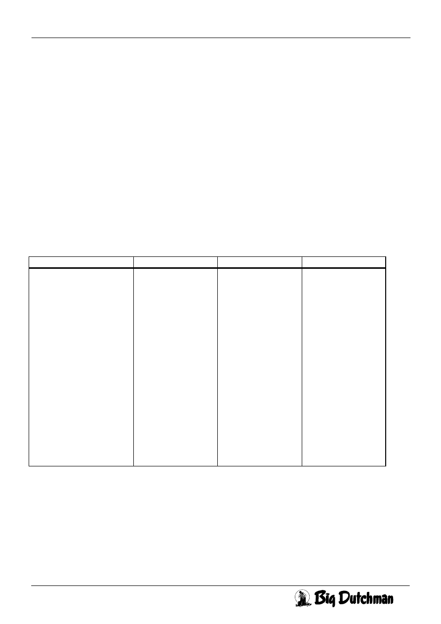
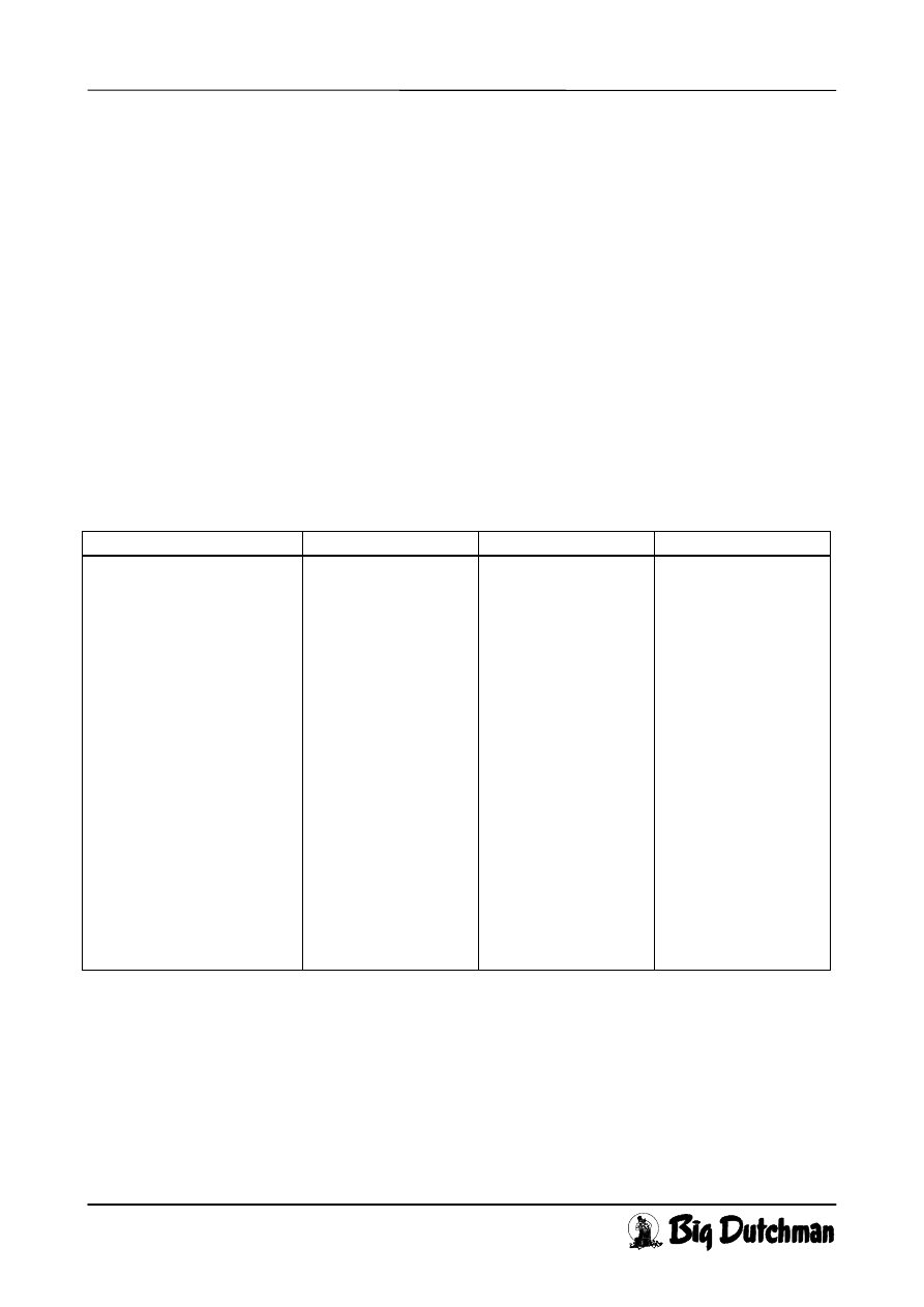
7. Technical Data
CL 75A-1 CL 75A-3 CL 75A-6
Operating voltage
Power consumption
Max. continuous running time
Max. torque
No. of wire wheel turns
Running time between end stop
No. of wire tracks and width
Wire
Wire length
Min. wire length and force
Max. wire length and force
Shipping weight
Shipping dimensions
Protection class
Control signal stepless
Control signal ON/OFF emerg.op.
Potentiometer
Potentiometer position closed
Potentiometer position open
Max. cable length at 1.5 mm²
Max. cable length at 2.5 mm²
Item No.
24V dc ± 15%
1,3 A
∞
75 Nm
1.2
2.5 to 6.3 min.
2 pcs. 5 mm
2 pcs. Ø4 mm ss
10 metres
25 cm/1771 N
55 cm/1026 N
14,6 kg
415
×
315
×
175 mm
IP 54
2-pot. free change-over co.
1 pot. free braker switch
10 k
Ω
0-4% of max.
90-95% of max.
≤
30 metres
≤
50 metres
432035
24V dc ± 15%
1,6 A
60 min.
75 Nm
2.4
2.5 to 3.5 min.
2 pcs. 5 mm
2 pcs. Ø4 mm ss
10 metres
53 cm/1743 N
107 cm/1053 N
15,4 kg
415
×
315
×
175 mm
IP 54
2 pot. free change-over co.
1 pot. free braker switch
10 k
Ω
0-4% of max.
90-95% of max.
≤
30 metres
≤
50 metres
432036
24V dc ± 15%
1,6 A
60 min.
75 Nm
4.8
5 - 7 min.
2 pc. 5 mm
2 pc. Ø4 mm ss
10 metres
116 cm/1688 N
203 cm/1110 N
15,2 kg
415
×
315
×
175 mm
IP 54
2 pot. free change-over co.
1 pot. free braker switch.
10 k
Ω
0-4% of max.
90-95% of max.
≤
30 metres
≤
50 metres
432037

CL 75A 24V STELLMOTOR
Seite 1
Bedienungsanleitung CL 75A 24V
Ausgabe: 27.05.98
ν
M 853 D
Inhaltsverzeichnis
1. PRODUKTBESCHREIBUNG ..............................................................................................................................2
Abb. 1 Bedienung ...............................................................................................................................................2
2. WARTUNG............................................................................................................................................................2
3. INSTALLATION ...................................................................................................................................................2
3.1 N
ORMALE STUFENLOSE
F
UNKTION
......................................................................................................................3
Abb. 2 “Stufenlos”, Prinzipdiagramm und Verbindung............................................................................. ..........3
3.2 D
IE
ON/OFF N
OTTÖFFNUNGSFUNKTION
.............................................................................................................4
Abb. 3“EIN/AUS-Notöffnung” Prinzipdiagram und Anschluß ............................................................................4
4. MONTAGE............................................................................................................................................................5
5. FEHLERSUCHE UND NOTBEDIENUNG..........................................................................................................7
Abb. 5 Steuerplatine und Schaltkondensator .......................................................................................................7
Abb. 6 Montage von Schalterleitungen ...............................................................................................................8
6. ERSATZTEILE UND ZUBEHÖR........................................................................................................................9
7. TECHNISCHE DATEN ........................................................................................................................................9
CL 75A 24V STELLMOTOR
Seite 2
Bedienungsanleitung CL 75A 24V
Ausgabe: 27.05.98
ν
M 853 D
1. Produktbeschreibung
CL 75A ist ein Stellmotor zur Regelung von Klappen und Ventilen, z.B. in Stallüftungsanlagen. CL 75A
hat 2 Drahtseile, deren Zuglänge und Zugrichtung unabhängig von einander eingestellt werden können.
CL 75A hat ein Rückführpotentiometer für Stellungsanzeige.
Es gibt einen Umschalter zwischen AUT. und MAN. (B). Der Stellmotor ist relaisgesteuert und stufenlos
steuerbar zwischen zu und offen. In der AUT-Stellung wird der Motor vom Klimacomputer, z.B. MC
34H, gesteuert. In der MAN-Stellung kann der Motor öffnen, stoppen oder schließen über den Schalter
(C). CL 75A hat eingebaute Endschalter und einen Thermokontakt zum Ausschalten des Motors, wenn er
zu heiß wird. Notbedienung von CL 75A erfolgt über eine Notöffnungskurbel, Warennr. 432020, oder
eine Akku Bohrmaschine und beigefügtes Kopplungsstück (D) durch das Loch (A).
CL 75A für 24V ist besonders auf Anlagen mit Notöffnung ausgelegt, wo die Notenergie in einer 24V
Batterie liegt.
Die ON/OFF Notöffnung, z.B. wo der Stellmotor ein Fenster ganz öffnet, ist auch möglich.
Abb. 1 Bedienung
2. Wartung
Man sollte regelmässig nachprüfen, daß die Seile intakt sind und in den Seilspuren nicht verschleißen.
Die Motorkohlen haben eine Lebensdauer von etwa 5.000 Betriebsstunden, die etwa 10 Jahre
Normalbetrieb entsprechen. Eine neue Satz Kohlen kann von SKOV bestellt werden, siehe Abschnitt 6,
Ersatzteile und Zubehör.
3. Installation
CL 75A wird durch ein Siebenleiterkabel mit der Automatikeinheit verbunden (Abb. 2), oder durch ein
Fünfleiterkabel (Abb. 3).
Nach der Installation den Schalter (B) auf MAN stellen, und den Motor durch den Schalter (C) von
Anschlag zu Anschlag laufen lassen um nachzuprüfen, daß die mechanische Verbindung in Ordnung ist.
Den Schalter (B) auf AUT stellen und nachprüfen, daß der Motor durch Bedienung der Automatikeinheit
öffnen, stoppen und schließen kann. Die Öffnungs- und Schließrichtung ist auf das Drahtseil aufgeklebt.
CL 75A 24V STELLMOTOR
Seite 3
Bedienungsanleitung CL 75A 24V
Ausgabe: 27.05.98
ν
M 853 D
3.1 Normale stufenlose Funktion
Den AUT./MAN. - Schalter (B) auf AUT. einstellen. Der Motor wird über Leitung 1 und 3 gesteuert.
Wenn CL 75A med 24V dc durch die Leitungen 1 (= +24V) und 3 (= 0V) gespeist wird, öffnet sich der
Motor. Umgekehrte Polarität schließt den Motor. Leitung 2 wird bei stufenloser Funktion nicht
verwendet.
Gleiche Polarität auf Leitung 1 und 3 wird zu einem Stopp führen. Falls Leitung 1, 3 oder beide
abgeschaltet werden, stoppt der Motor. Die Leitung 4 (= +24V dc) und 5 (= 0V) müßen immer
angeschloßen sein, damit der Motor manuell geöffnet/geschloßen werden kann über die Schalter (B) und
(C).
Der Potentiometer wird z.B. 10V dc zugeführt zu Leitung 6 (= +10V) und Leitung 8 (= 0V). Leitung 7
wird dann bei geschloßenem Motor 0V haben, etwa 5V bei halb offenem und etwa 10V bei ganz offenem
Motor.
Bei automatischem Betrieb den Umschalter (B) auf AUT. einstellen.
Bei Stromausfall kann der Motor durch das mitgelieferte Kupplungsstück (D) und eine Bohrmaschine
(Akku am liebsten) bedient werden. Der Verschluß (A) wird auch mit dem Kupplungsstück abgeschraubt.
Abb. 2 “Stufenlos”, Prinzipdiagramm und Verbindung
CL 75A 24V STELLMOTOR
Seite 4
Bedienungsanleitung CL 75A 24V
Ausgabe: 27.05.98
ν
M 853 D
3.2 Die ON/OFF Nottöffnungsfunktion
Den AUT./MAN. Umschalter (B) auf AUT. stellen.
Die Funktion wird für z.B. Notöffnung von einem Fenster in einem Stall mit “diffuser” Abluft benutzt. Der
Motor kann über einen DOL 2012 Termostat oder einem mechanischen Danfoss Termostat + MC 78M
Notöffnung gesteuert werden.
Der Motor wird ON/OFF gesteuert (öffnen/schließen auf Leitung 2 mit nur einem Relais Endschalter.
Wenn die Temperatur zu hoch wird soll der Relaisschalter des Termostats +24V für Leitung 2
Ausschalten, und der Motor öffnet ganz.
So lange die Leitung 2 +24V hat, wird der Motor ganz geschlossen gehalten.
Leitung 1 (= +24V) und 3 (= 0V) müssen bei dieser Verwendung immer angeschlossen sein.
Leitung 4 (= +24V dc) und 5 (= 0V) müssen immer angeschlossen sein, damit der Motor mit den
Umschaltern (B) und (C) manuell geöffnet/geschlossen werden kann.
Abb. 3“EIN/AUS-Notöffnung” Prinzipdiagram und Anschluß
Kabellänge Querschnitt
0 →
30 m 1,5 mm²
20
→
50 m 2,5 mm²
Kabel Querschnitt
CL 75A 24V STELLMOTOR
Seite 5
Bedienungsanleitung CL 75A 24V
Ausgabe: 27.05.98
ν
M 853 D
4. Montage
CL 75A wird mit 2 Drahtseilscheiben und entsprechenden Drahtseilen geliefert. Wenn nur ein Drahtseil
angewendet werden soll, wird das aü
β
erste Drahtseil abmontiert. Um dieselben Bolzen wieder anwenden
zu können, die Seilscheiben wieder montieren.
Wenn 3 Drahtseile angewendet werden sollen, kann eine extra Seilscheibe mit Drahtseil, Warennr.
432925, montiert werden. Dieselben Bolzen können angewendet werden.
CL 75A senkrecht oder waagerecht an die Wand montieren. Bei waagerechter Montage sollte die Achse
nach unten kehren, um zu hindern, daß Wasser eindringt. In wärmeren Ländern sollte man vermeiden, daß
die Sonne direkt auf CL 75A scheint. Für die Montage 3 oder 4 Stck. 10 mm durchgehende Bolzen
verwenden. Für eine evtl. Notöffnung sollte bei (A) auf Abb. 1 genügender Raum für eine
Notöffnungskurbel oder eine Akku Bohrmaschine frei gelassen werden. Die Seilführung kann in jeder
beliebigen Richtung erfolgen, auch durch die Mauer. Die Seile sind auf die Seilspur zu wickeln, damit eine
korrekte Zug- oder Nachlaßlänge erzielt wird.
Wenn man einen Stellmotor wickeln soll, sollte er immer im
Endschalter sein. Abb. 4 zeigt wo zu messen, um
Näherungswerte im Schema zu bekommen. Bitte bemerken,
das min. 3 mm zum Au
β
enperipherie frei sein soll und da
β
die
Nabe immer von einer Seilschicht “gedeckt” werden mu
β
, wie
im Abbildung gezeigt. Die Abbildung zeigt auch die Definition
von “Anzahl Seilschichte = 1”.
Nachstehende Tabelle zeigt den Zusammenhang zwischen
Belastung, der Anzahl von Seilschichten und den Zug- oder
Nachlaßlängen. 1000 N ist gleich 98 kg.
Abb. 4
CL 75A 24V STELLMOTOR
Seite 6
Bedienungsanleitung CL 75A 24V
Ausgabe: 07.09.98
ν
M 853 D
CL 75A-1
Ma
β
zu Einseitiger Zug Balanziert
Anzahl Dra-
htschichte
Zuglänge
[mm]
Nachla
β
längen
[mm]
Peripherie
vor Zug/Nachl.
Zugkraft
[N]
Moment
[Nm]
Zugkraft
[N]
Moment
[Nm]
1 237 - 48 1794 56 2384 75
2 260 232 45 1748 60 2170 75
3 284 256 42 1702 64 1992 75
4 307 279 39 1656 68 1840 75
5 331 303 36 1610 71 1710 75
6 354 326 33 1564 74 1597 75
7 377 349 30 1498 75 1498 75
8 401 373 27 1411 75 1411 75
9 424 396 24 1379 75 1333 75
10 447 419 21 1333 75 1263 75
11 471 443 17 1263 75 1201 75
12 494 466 14 1201 75 1144 75
13 517 489 11 1144 75 1092 75
14 541 - 8 1092 75 1045 75
CL 75A-3
1 502 - 48 1767 59 2251 75
2 549 - 45 1721 63 2059 75
3 596 484 42 1674 66 1898 75
4 642 530 39 1628 69 1760 75
5 689 577 36 1582 72 1640 75
6 736 624 33 1536 75 1536 75
7 783 670 30 1445 75 1445 75
8 829 717 27 1379 75 1363 75
9 876 764 24 1363 75 1290 75
10 923 811 21 1290 75 1225 75
11 969 857 17 1225 75 1166 75
12 1016 904 14 1166 75 1112 75
13 1063 951 11 1112 75 1064 75
14 - - 8 1064 75 1019 75
CL 75A-6
1 1117 - 48 1711 64 2025 75
2 1210 - 45 1665 67 1868 75
3 1303 - 42 1619 70 1735 75
4 1397 - 39 1573 73 1618 75
5 1490 - 36 1517 75 1517 75
6 1584 1135 33 1427 75 1427 75
7 1677 1229 30 1379 75 1348 75
8 1771 1322 27 1348 75 1277 75
9 1864 1416 24 1277 75 1213 75
10 1958 1509 21 1213 75 1155 75
11 2051 1603 17 1155 75 1102 75
12 - 1696 14 1102 75 1054 75
13 - 1789 11 1054 75 1010 75
14 - - 8 1010 75 970 75
CL 75A 24V STELLMOTOR
Seite 7
Bedienungsanleitung CL 75A 24V
Ausgabe: 27.05.98
ν
M 853 D
5. Fehlersuche und Notbedienung
Während Normalbetrieb ist es in Ordnung, daß R2 auf der Steuerplatine warm wird.
Wenn der Motor nicht laufen kann, den Schalter (B) auf MAN stellen und versuchen durch Schalter (C)
den Motor zu betätigen. Wenn das möglich ist, die Steuersignalverbindung zur Automatikeinheit und evtl.
auch das Rücksignal vom Potentiometer nachprüfen.
Wenn die Betätigung des Motors nicht möglich ist, nachprüfen, ob 24V dc vorhanden ist. (Falls die
Ventile ganz offen sind, nach unten schließen).
Wenn ja, den Schalter (C) auf Öffnen (aufwärts) stellen, den Deckel abnehmen und kontrollieren, ob der
Stecker (F) eingesteckt ist. Die Spannung zum Motor zwischen Klemme (G) und (H) (Abb. 5,
Steuerplatine) messen. Ist die Spannung in Ordnung und der Motor läuft nicht, die Kohle (P)
kontrollieren. Hilft dies nicht, den Motor auswechseln. Falls keine Spannung, nachprüfen, ob die
Überlastunglampe (I) rot leuchtet. Leuchtet (I), ist der Motor überlastet (zu viele Ventile, Drahtseil falls
justiert). Überlastung entfernen, (B) auf MAN stellen und (C) auf 0 (Mittelstellung) für 10 Sekunden,
damit die Überlastungssicherung abkühlen kann. Den Schalter (C) auf (aufwärts) oder (abwärts) stellen.
Wenn keine Spannung, die Steuerplatine auswechseln.
Abb. 5 Steuerplatine und Schaltkondensator
Auswechselung der Steuerplatine:
Die Motorleitungen (G) und (H) abnehmen. Den Stecker (F) zum Schalter abnehmen. Die 3 Schrauben
durch den mitgelieferten Sechskantschlüssel lösen und die Steuerplatine abbauen. Die Potentiometerwelle
(K) der neuen Steuerplatine justieren, damit sie in das Loch des großen Zahnrades hinein paßt. Die
Steuerplatine montieren. Wenn der Motor vom Endschalter aktiviert ist, die Arme der Endschalter (J) und
(L) auf den Nocken des Zahnrades hinaufsetzen. Die Schrauben anziehen und die Leitungen und Stecker
montieren. Den Motor wie unter Installation erwähnt prüfen.
CL 75A 24V STELLMOTOR
Seite 8
Bedienungsanleitung CL 75A 24V
Ausgabe: 27.05.98
ν
M 853 D
Auswechselung des Getriebemotors:
Die Drahtseile entlasten und die Sechskantschraube (E) Abb. 1, lösen. Danach ist es möglich, das
komplette Drahtseilrad von der Welle abzubauen. Bitte aufpassen, daß die Seile vom Drahtseilrad nicht
abfallen und daß die Nut (das Metallstück) nicht aus die Nutung (den Schlitz) der Achse fällt. Die
Steuerplatine abnehmen, siehe oben. Die 4 Bolzen, mit denen das Getriebe zur Konsole festgemacht ist,
durch den mitgelieferten langen Sechskantschlüssel abnehmen. Falls der neue Motor nicht mit
Schaltkondensator (M) ausgestattet ist, den Schaltkondensator (M) vom defekten auf dem neuen Motor
bauen, bevor der neue Motor montiert wird.
Die Motorkappe über die Schraube (N) abmontieren. Die Schrauben (P) lösen und die 2 Leitungen
ausziehen. Den Schaltkondensator auf dem neuen Motor montieren. Die Montage passiert in umgekehrter
Reihenfolge. Vor der Montage des Drahtseilrades die Keilbahn der Welle wie vorher stellen (bei CL 75A-
3 sollte die Welle auch zur korrekten Umdrehungsposition justiert werden, vgl. gegenüber montierte
Kunststoffzahnräder). Den Motor wie unter Installation prüfen.
Auswechselung der Schalter:
Der Ersatzteil besteht aus 2 Schaltern und einem Leitungssatz. Den Entlastungsbügel im Deckel
abnehmen, die Leitungen aus den Schaltern herausziehen und die Schalter durch Zusammendrücken der
Widerhaken aus dem Deckel pressen. Die neuen Schalter montieren, bitte nicht vergessen, den Schalter
mit 3 Stellungen rechts zu montieren (Vorderansicht). Die Leitungen montieren, siehe Abb. 6, Montage
von Schalterleitungen, die auch an der inneren Seite des Deckels aufgeklebt ist. Den Motor wie unter
Installation erwähnt prüfen.
Abb. 6 Montage von Schalterleitungen
Notbedienung:
Wenn alles versagt, kann die Anlage von Hand geöffnet werden. Den Gewindestöpsel bei (A) Abb. 1,
abschrauben. Das Kupplungsstück bei (A) auf eine Notöffnungskurbel oder eine Bohrmaschine (Akku am
liebsten) montieren. Das Kupplungsstück in das Loch bei (A) hineinführen, bis es mit der Motorwelle zum
Eingriff kommt. Rechts herum und der Getriebemotor wird die Anlage öffnen. Nicht zu viel öffnen oder
schließen, da die mechanische Installation sonst beschädigt werden kann.
CL 75A 24V STELLMOTOR
Seite 9
Bedienungsanleitung CL 75A 24V
Ausgabe: 07.09.98
ν
M 853 D
6. Ersatzteile und Zubehör
Folgende Teile können bei SKOV bestellt werden:
Ersatzteile 432904 CL 75A-1 Getriebemotor 24 V
432908 CL 75-3/75A-3 Getriebemotor 24 V
432919 CL 75A-6 Getriebemotor 24V
432910 CL 75/75A-24 V Motorkohlen
432953 CL 75/75A-24V-R Steuerplatine
432924 CL 75/75A Schalter 24V/230V
Zubehör: 432020 Notöffnungskurbel für CL 75/75A
432925 CL 75A Seilscheibensatz, 1 Drahtseil
7. Technische Daten
CL 75A-1 CL 75A-3 CL 75A-6
Nennspannung
Stromverbrauch
Max. kontinuierliche Betriebszeit
Max. Drehmoment
Umdrehungen des Drahtseilrades
Laufzeit zwischen Endestopp
Anzahl Seilspuren und Breite
Drahtseil
Drahtseillänge
Min. Zuglänge und Kraft
Max. Zuglänge und Kraft
Versandgewicht
Versandabmessungen
Schutzart
Steuersignal Stufenlos
Steuersignal EIN/AUS Notöffn.
Potentiometer
Potentiometer Position geschloßen
Potentiometer Position offen
Max. Kabellänge bei 1,5 mm²
Max. Kabellänge bei 2,5 mm²
Warennr.
24V dc ± 15%
1,3 A
∞
75 Nm
1.2
2,5 - 3,5 Min.
2 Stck. 5 mm
2 Stck. Ø4 mm V2A
10 Meter
25 cm/1771 N
55 cm/1026 N
14,6 kg
415
×
315
×
175 mm
IP 54
2 potentialfreie Schalter
1 potentialfreier Ausschal.
10 k
Ω
0-4% von max.
90-95% von max.
≤
30 Meter
≤
50 Meter
432035
24V dc ± 15%
1,6 A
60 Min.
75 Nm
2.4
2,5 - 3,5 Min.
2 Stck. 5 mm
2 Stck. Ø4 mm V2A
10 Meter
53 cm/1743 N
107 cm/1053 N
15,4 kg
415
×
315
×
175 mm
IP 54
2 potentialfreie Schalter
1 potentialfreier Ausschal.
10 k
Ω
0-4% von max.
90-95% von max.
≤
30 Meter
≤
50 Meter
432036
24V dc ± 15%
1,6 A
60 Min.
75 Nm
4.8
5 - 7 Min.
2 Stck. 5 mm
2 Stck. Ø4 mm V2A
10 Meter
116 cm/1688 N
203 cm/1110 N
15,2 kg
415
×
315
×
175 mm
IP 54
2 potentialfreie Schalter
1 potentialfreier Ausschal.
10 k
Ω
0-4% von max.
90-95% von max.
≤
30 Meter
≤
50 Meter
432037
Wyszukiwarka
Podobne podstrony:
PR CYW PR ROP WYKLAD 26
26 poniedziałek
26 Inne ideologie
ref 2004 04 26 object pascal
plik (26) ppt
W11 Starzenie komórkowe (asus Komputer's conflicted copy 2012 05 26)
25 26
26 (11)
26 Dom
antropomotoryka 26 2004 id 6611 Nieznany (2)
200906180002 7 26
26 9 11
1996 10 26 praid 18571 Nieznany
BTI AWAX 26 27 45
2002 03 26
7 26
2001 10 26
więcej podobnych podstron