APPLICATION NOTE
XAPP328 (v1.1) December 31, 1999
1
1-800-255-7778
Introduction
MP3 portable players are the trend in music-listening technology. These players do not include any mechanical movements,
thereby making them ideal for listening to music during any type of activity. MP3 is a digital compression technique based on
MPEG Layer 3 which stores music in a lot less space than current CD technology. Software is readily available to create
MP3 files from an existing CD, and the user can then download these files into a portable MP3 player to be enjoyed in almost
any environment.
As with any portable, battery-operated device, power dissipation must be minimized. The CoolRunner series is a family of
advanced 3-volt and 5-volt complex programmable logic devices (CPLDs) with extremely low power dissipation which
makes them ideal for this application. This application note will address the design of a MP3 portable player using a 3.3V
256 macrocell CoolRunner CPLD (XCR3256XL) as the main controller.
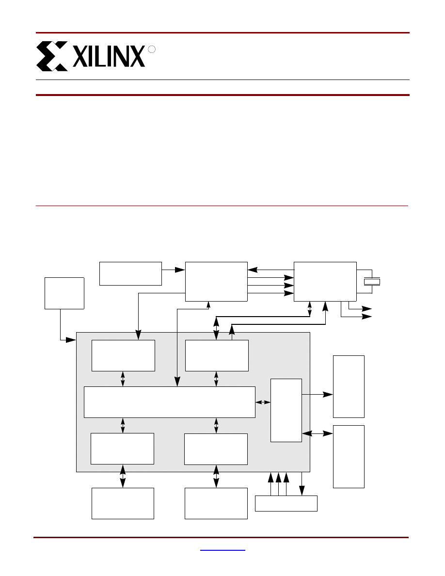
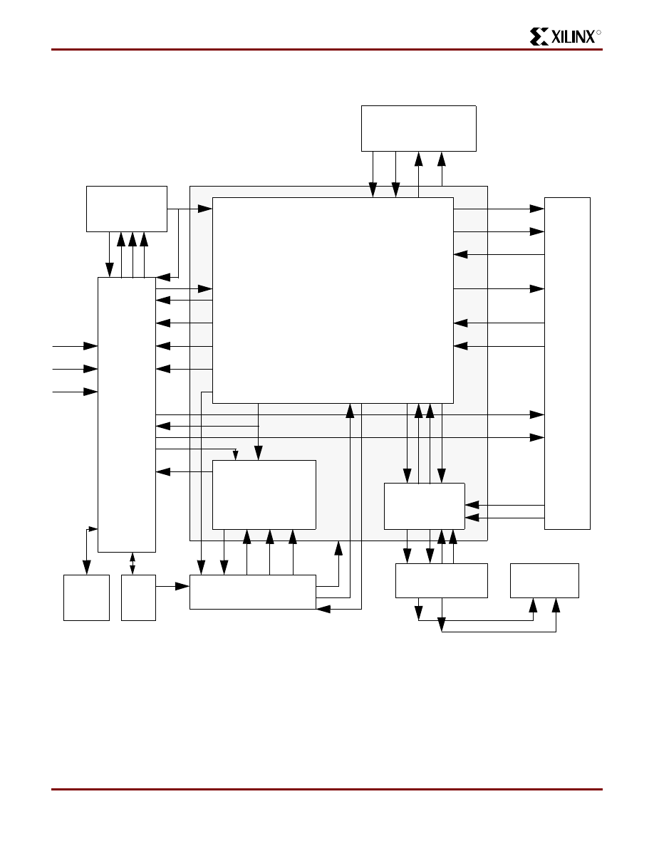
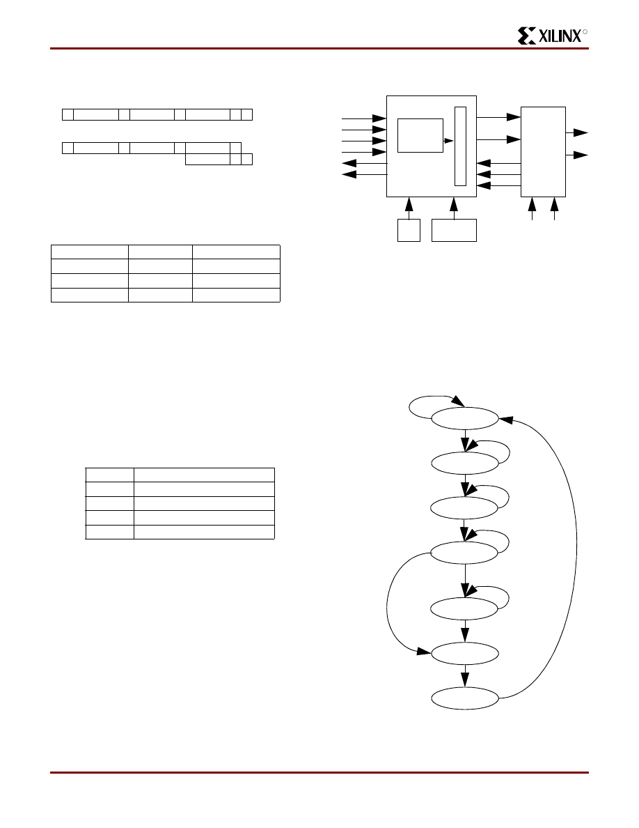
MP3 Portable Player Block Diagram
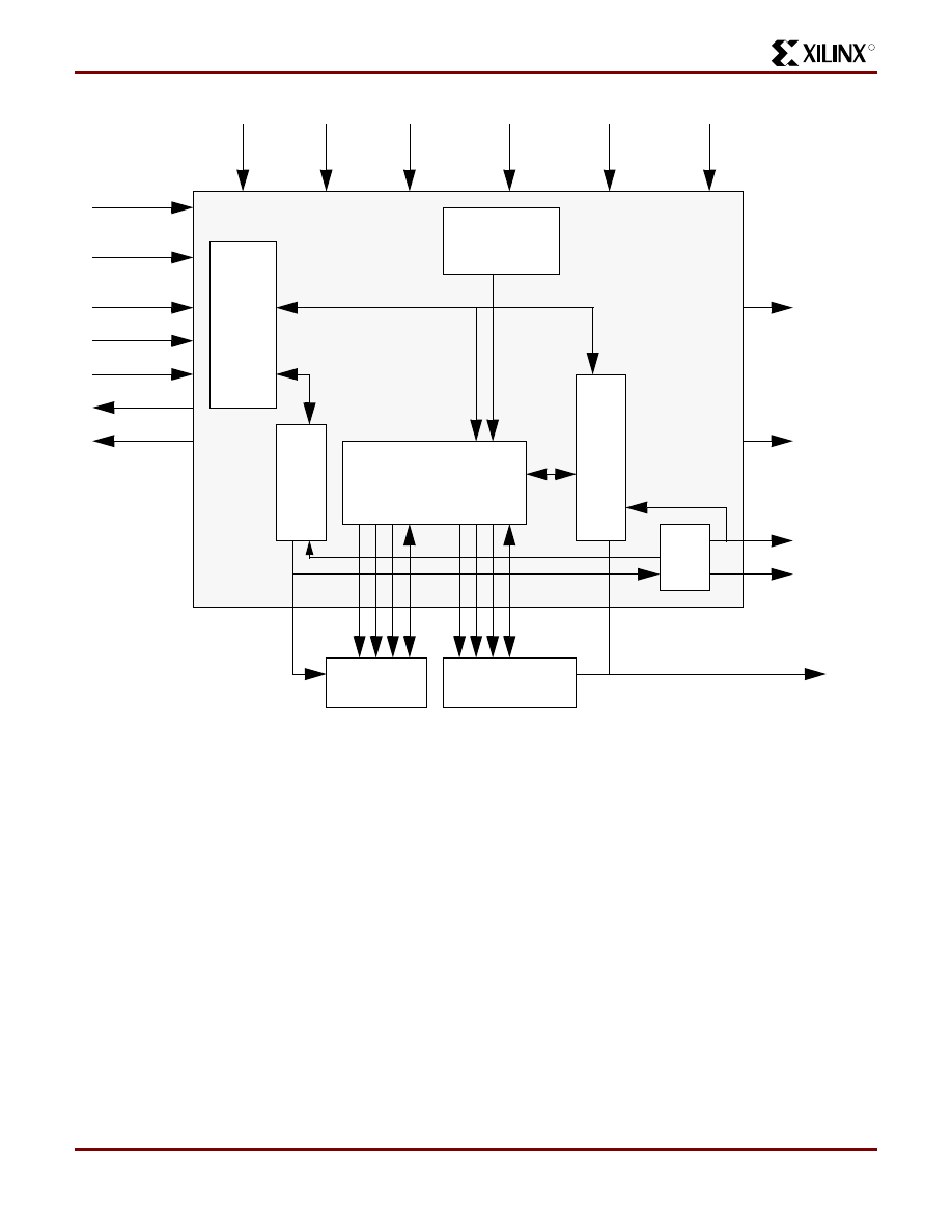
The block diagram of the CoolRunner MP3 Portable Player
is shown in
. The shaded area shows the logic that
is contained in the CoolRunner CPLD. All other blocks are
external devices that can be obtained commercially. The
CPLD logic blocks and the external devices in this diagram
are briefly described in the section following this diagram.
Figure 1: MP3 Player Block Diagram
Design of a MP3 Portable Player
using a CoolRunner CPLD
XAPP328 (v1.1) December 31, 1999
R
PC Parallel Port
Parallel Port
U
s
er
Int
e
rf
ace
Flash
Flash Bank
Interface
Control
Us
er
Inter
fac
e
Con
tr
o
l
L
C
D Di
s
p
la
y
Main Control Logic
I2C Master
MP3 Decoder
Digital/Analog
Battery
Power Mgmt
2MHz
Oscillator
14
.7
25
M
H
z
H
ea
dp
hon
es
SDA
SCL
CLKOUT
WSI
CLI
DRI
OUTL
OUTR
Po
w
e
r O
K
M
P
3 D
a
ta
, S
tat
us
Addr, Data
Control
MP3 Data
From PC
ON/OFF
Play
Stop
Rew/FF
Volume
Track
MAS3507D
DAC3550A
Converter
Mute
Download
Rewind
Fast Forward
Error
Play
JTAG Port
TDI
TM
S
TCK
TD
O
CoolRunner CPLD
Application Note: CoolRunner

Design of a MP3 Portable Player using a CoolRunner CPLD
XAPP328 (v1.1) December 31, 1999
2
1-800-255-7778
R
CoolRunner CPLD Logic Modules
Main Control Logic
The Main Control Logic block provides the intelligence of
the CPLD logic and controls all of the various functions.
This logic block is broken into smaller functions such as
MPEG chip control, Play logic, etc. as seen in
Parallel Port Interface
This block of logic communicates with the PC over the par-
allel port for downloading of MP3 data. The design of this
MP3 player assumes that a software package is designed
to allow users to “rip” CDs and download a collection of
their favorite MP3 files to this portable player. The block
diagram of this logic is seen in
Flash Control
The Flash Bank shown in
consists of a 32MByte
flash called the Song Flash and a 2Mbyte Flash called the
Starting Address Flash. The Flash Control Logic shown in
controls the Song Flash memory for the storing
and retrieving of MP3 data and the Starting Address Flash
Memory which stores the address of the Song Flash where
the beginning of each song is stored. The Starting Address
Flash also stores the last address of MP3 data so that the
end of song data can easily be determined.
User Interface Control
The user interface for the MP3 player will consists of con-
trols that provide the user the following functions:
-
On/Off
-
Play/Stop
-
Rewind/Fast Forward
-
Volume/Mute
This block of logic is shown in
and is responsible
for interfacing to these controls and providing signals to the
Main Control Logic. This logic also updates the LCD dis-
play with the MP3 portable player status and current func-
tion.
I2C Master
Control and setup of the DAC3550A is done over the I2C
bus. This block of logic is an I2C Master and drives the
SCL/SDA signals. A simple control interface from the Main
Control Logic triggers the I2C master to begin a data trans-
fer. Since this is a local I2C bus, this logic will be the only
I2C bus master, therefore, no arbitration logic or slave logic
is required. The block diagram from the I2C Master Logic is
shown in
Power Management
The Power Management Logic shown in
tors the voltage indicator from the MAS3507D. It provides
the power-up reset for the CPLD logic. This logic initiates a
power down operation if voltage level goes below the mini-
mum required voltage or the user turns the MP3 portable
player OFF.
External Devices
MAS3507D MP3 Decoder Chip
The MAS3507D from Micronas Intermetall is a MPEG1 and
MPEG2 Layer 2 and 3 audio decoder for use in audio
broadcast or memory-based playback applications. This
chip is ideal for a portable MP3 player because it contains
embedded memory, an embedded DC/DC converter and
has very low power consumption. It directly connects with
the Micronas Intermetall DAC3550A Stereo Audio DAC to
complete the MPEG decoding and playback process.
The DC/DC converter of the MAS3507D will be used to
supply the power for the MP3 portable player. The DC/DC
converter has a separate enable from the MPEG decoder
portion of the chip, therefore these functions can be con-
trolled separately as needed.
The MAS3507D can be controlled via an I2C bus or
through the parallel interface. MPEG data is input serially
into the chip or in a parallel manner through the parallel
interface. The chip outputs the audio data in I2S format.
The input stream can be totally asynchronous to the output
audio data. The chip supports digital volume, bass, and tre-
ble adjustments.
DAC3550A Stereo Audio DAC
The DAC3550A Stereo Audio DAC from Micronas Inter-
metall is a single-chip, high-precision, dual digital-to-analog
converter designed for audio applications. The employed
conversion technique is based on oversampling with
noise-shaping. The DAC3550A provides line-out, head-
phone/speaker amplifiers, and volume control. With an
external crystal, the DAC3550A can provide the clock
source for the MAS3507D.
The DAC3550A is controlled over the I2C bus. It accepts
the audio data in I2S format and ideally complements the
MAS3507D.
Flash
The Flash block actually contains two separate Flash Mem-
ory banks - the Song Flash and the Starting Address Flash.
32Mbytes of Flash in the Song Flash is provided for storage
of MP3 songs. 32MBytes of Flash should provide approxi-
mately 60 minutes of playing enjoyment. This bank of Flash
memory is composed of two 28F128J3A 3-volt 128Mbit
Intel StrataFlash memories that provide reliable two bit per
R
Design of a MP3 Portable Player using a CoolRunner CPLD
XAPP328 (v1.1) December 31, 1999
www.xilinx.com
3
1-800-255-7778
cell storage technology at a low cost. Benefits include more
density in less space and a high-speed interface which is
ideal for a portable MP3 player.
The Starting Address Flash stores the starting address of
each song in the Song Flash and the address where the
song data ends. The Intel 28F320J3A provides 2MByte of
Flash storage for the Starting Address Flash.
Operational Flows
This section will detail the functions and operations of the
MP3 portable player:
•
ON/OFF
•
Download of MP3 data files (songs)
•
Play/Stop
•
Rewind/Fast Forward
•
Volume Adjustments
•
Mute
These sections provide the reader with an overall view of
the steps in each operational flow so that the detailed Cool-
Runner CPLD logic blocks can be more easily understood.
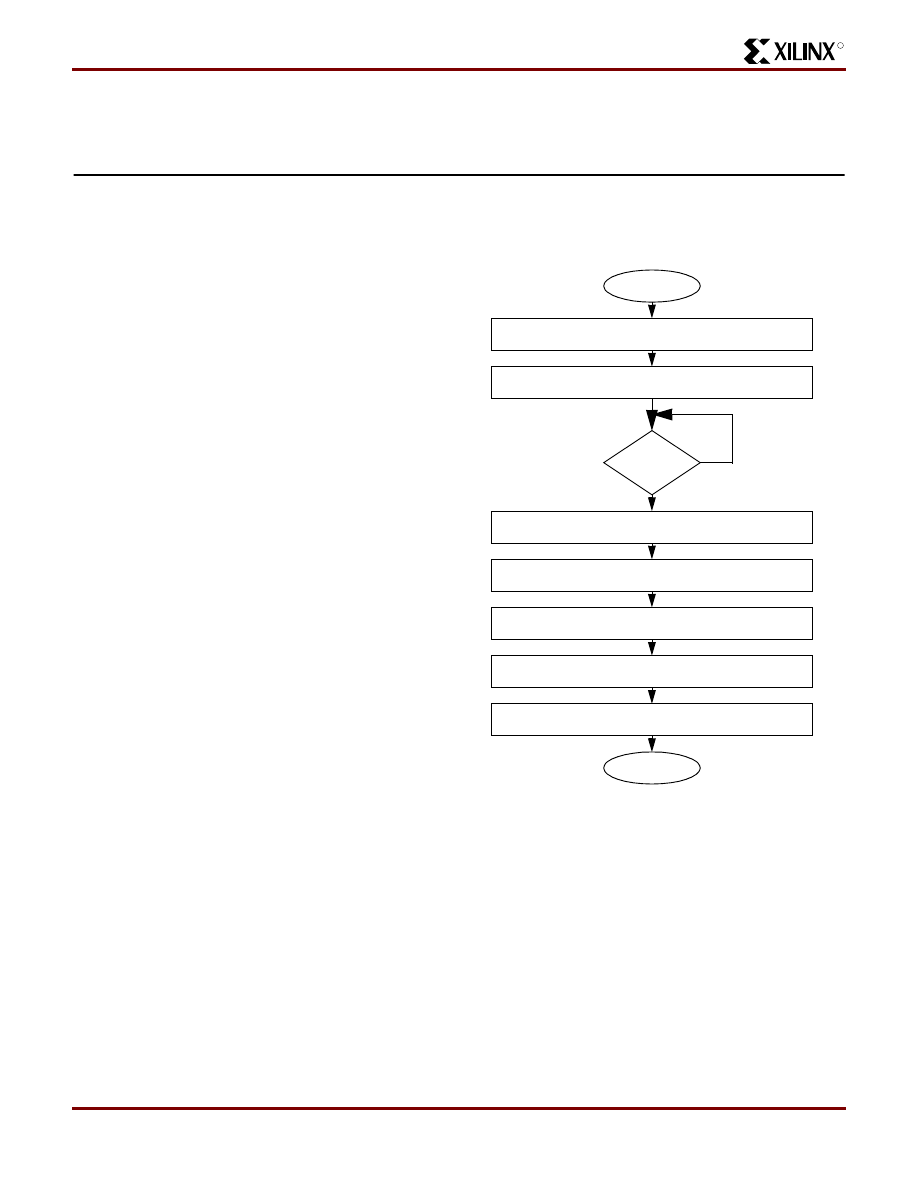
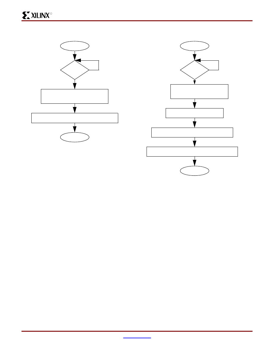
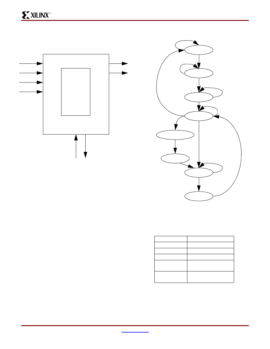
ON/OFF
The function of the ON/OFF switch when in the ON position
will be to apply the battery power to the DC/DC converter of
the MAS3507D. This will, in turn, supply power to the rest
of the system. The CoolRunner CPLD and other devices
will stay in reset until the power has stabilized. The
MAS3507D outputs the PUP signal indicating that the
power supply voltage exceeds its minimal level. The PUP
signal from the MAS3507D is sampled to insure that the
power is stable. The I2S format settings of the DAC3550A
need to be configured to match the I2S output format of the
MAS3507D. This is done via an I2C register write.
(
Figure 2: ON Operation
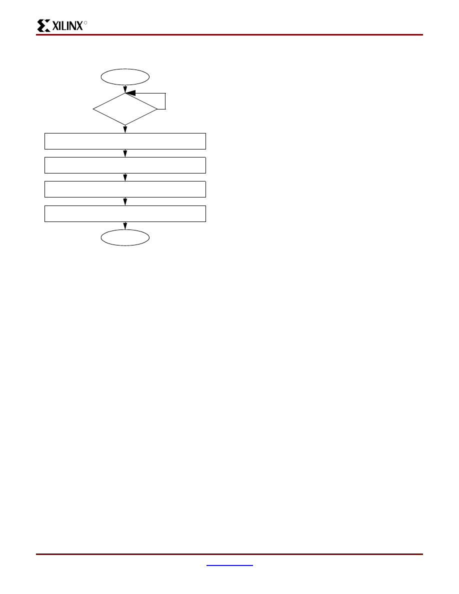
When the ON/OFF switch is in the OFF position, or the
PUP signal from the MAS3507D indicates that the power
supply voltage has dropped below the minimal required
level, the operation of the MP3 portable player must be dis-
abled. When either of these situations occur, the
MAS3507D is disabled to stop any I2S data to the
DAC3550A. The DAC3550A is then put into a low power
mode via an I2C register write. At this point, power from the
START
Battery Power is Switched to
Power Mgmt Logic asserts RESET
LCD indicates Power is On
END
PUP = 1?
Power Mgmt Logic negates RESET
Change DAC I2S Settings
Write $1F to SR_REG ($C1) via I2C
YES
NO
Load Volume Counter with default value “101100”
Set Parallel Port bit nAck
MAS3507D DC/DC converter
Design of a MP3 Portable Player using a CoolRunner CPLD
XAPP328 (v1.1) December 31, 1999
4
1-800-255-7778
R
batteries is removed from the DC/DC converter of the
MAS3507D and the system powers down. (
Figure 3: OFF Operation
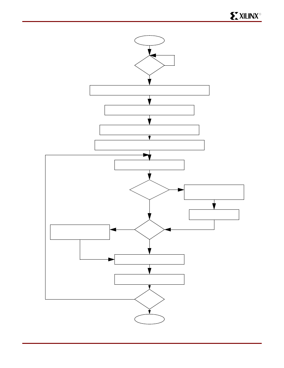
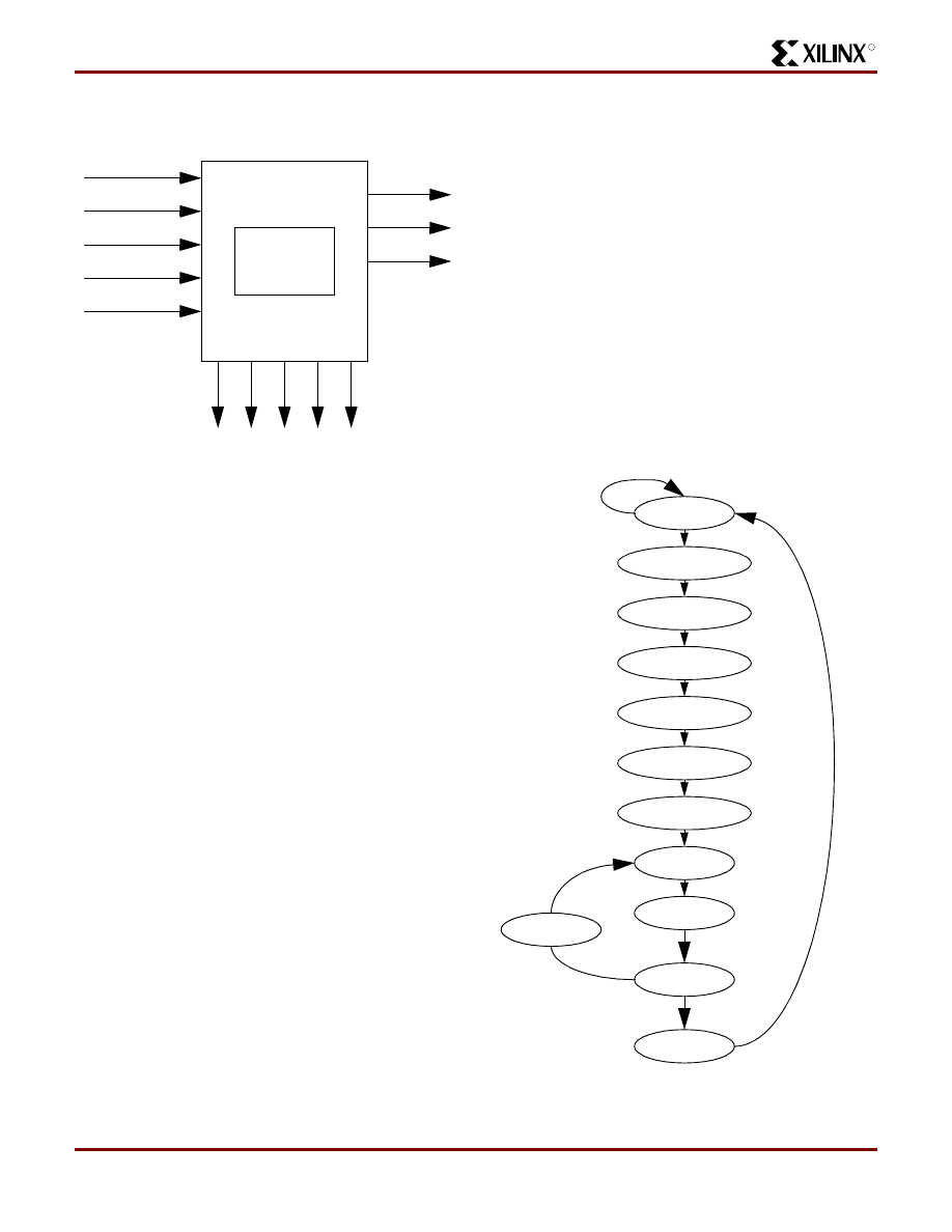
Download of MP3 Data Files (songs)
This design assumes that there will be a software package
that accompanies this hardware that provides the method
of organizing files on the PC for download into the MP3 por-
table player. This software will control and define the bits of
the parallel port (the definition of the parallel port bits is pro-
vided in the section detailing the Parallel Port Interface
Logic). When the software is ready to begin the download
operation, it sets a bit to indicate that a download operation
is starting. Please note that the download operation takes
priority over all other functions, i.e, all other user-interface
functions are ignored at this time. The portable MP3 player
must be powered on for the download operation to take
place.
To reduce power, MPEG decoding is disabled by setting
the MAS3507D signal WSEN to ‘0’ and the DAC3550A is
put in low-power mode by writing a ‘1’ to the PWMD bit of
the GCFG register via the I2C bus.
Every download operation erases the Song Flash and
Starting Address Flash memories. The entire set of music
chosen by the user via the PC software is then downloaded
into the Flash memory. After the Flash memory has been
erased, the address counter for the Flash is reset so that
the download begins at address 0. The Track Number is
also reset.
The LCD display of the MP3 portable player indicates that a
download is taking place. Data is obtained from the parallel
port via handshaking similar to that done on a
MC68000-like protocol. Once a data byte has been
received, it is written into the Song Flash and the address
counter is incremented. This process continues until the
software indicates that the download operation is complete.
The start of each song is marked by the PC software with a
bit in the parallel port called SONG_ST. When this bit is set,
the address of the Song Flash is stored in another small
Flash that creates a table of the starting addresses of the
songs in memory. The index into this table is the Track
Number. This table is used for Rewind and Fast Forward
operations. The Track Number is incremented for each new
song. The PC software marks the last byte of MP3 data
with the LAST_BYTE bit in the parallel port. When this bit is
set, the address of the Song Flash is stored in the Starting
Address Flash as the ending address of MP3 data.
START
Battery Power is removed from DC/DC converter
System powers down
END
Disable MP3 Decoding and I2S Data
Set MAS3507D WSEN = 0
Put DAC3550A in Low Power Mode
Set PWMD = 1 in GCFG Register via I2C
PUP=0
or OFF?
NO
YES
R
Design of a MP3 Portable Player using a CoolRunner CPLD
XAPP328 (v1.1) December 31, 1999
www.xilinx.com
5
1-800-255-7778
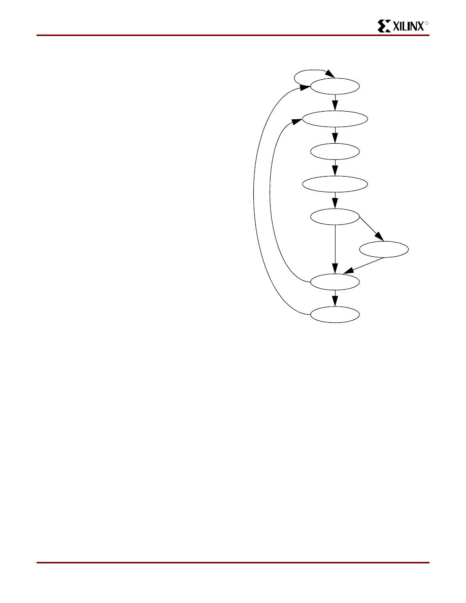
The flow of the download operation is shown in
.
Figure 4: Download Operation
Store Song Flash Address in
Starting Address Flash
(MSB=1)
START
Indicate Download Operation on LCD Display
Erase Song Flash & Reset Song Flash Address
Disable MPEG Decoding and put DAC in low power mode
Get Data Byte from Parallel Port
END
Last Byte?
Write Data Byte to Song Flash
Increment Song Flash Address
Download?
NO
YES
NO
YES
Start Bit?
Store Song Flash Address in
YES
NO
Starting Address Flash
Increment Track Number
Erase Starting Address Flash & Reset Track Number
WSEN = 0, PWMD = 1
(MSB = 0)
Download?
NO
YES

Design of a MP3 Portable Player using a CoolRunner CPLD
XAPP328 (v1.1) December 31, 1999
6
1-800-255-7778
R
Play/Stop
The Play operation begins when the user presses the Play
button. The MP3 decoding function of the MAS3507D is
then enabled and the DAC3550A is taken out of low-power
mode. Byte-wide data is read from the Flash and loaded
into the MAS3507D via the DMA mode using the parallel
port of the MAS3507D. Please see the MAS3507D data
sheet for more details on this mode of transferring MP3
data. As the MP3 data is read from the Song Flash, the
address of the Song Flash is compared with the starting
address of the next track stored in the Starting Address
Flash. If these addresses match, the User Interface Control
logic is signalled that a new song has started and the LCD
Display indicates the new track number.
Once the data from the Song Flash is loaded into the
MAS3507D, the Song Flash address is incremented so that
the next byte is ready for loading. This process continues
until the address of the Song Flash matches the end
address stored in the Starting Address Flash. At this point,
the Song Flash address is reset and the MP3 portable
player begins playing songs from the beginning of the Song
Address Flash.
R
Design of a MP3 Portable Player using a CoolRunner CPLD
XAPP328 (v1.1) December 31, 1999
www.xilinx.com
7
1-800-255-7778
The Play operation is terminated when another operation (
Rewind, Fast Forward, Stop) is chosen. (
Figure 5: Play Operation
The Stop operation sets the address of the Song Flash to
the starting address of the current track. When the user
presses “Play” after a Stop operation, the MP3 Player
START
Indicate Play Operation on LCD Display
Read Data from Flash
Enable MPEG Decoding and put DAC in normal mode
Handshake Data to MAS3507D
END
Play?
Increment Flash Address
End of MP3 Data?
Play?
NO
YES
YES
YES
NO
NO
Start of Song?
Update LCD Display with
Track #
YES
NO
WSEN = 1, PWMD = 0
Reset Song Flash Address
and Track #
MAS3507D
Rdy?
YES
NO
via PIO-DMA Parallel Port Mode
Design of a MP3 Portable Player using a CoolRunner CPLD
XAPP328 (v1.1) December 31, 1999
8
1-800-255-7778
R
begins playing at the beginning of the current track.
(
Figure 6: Stop Operation
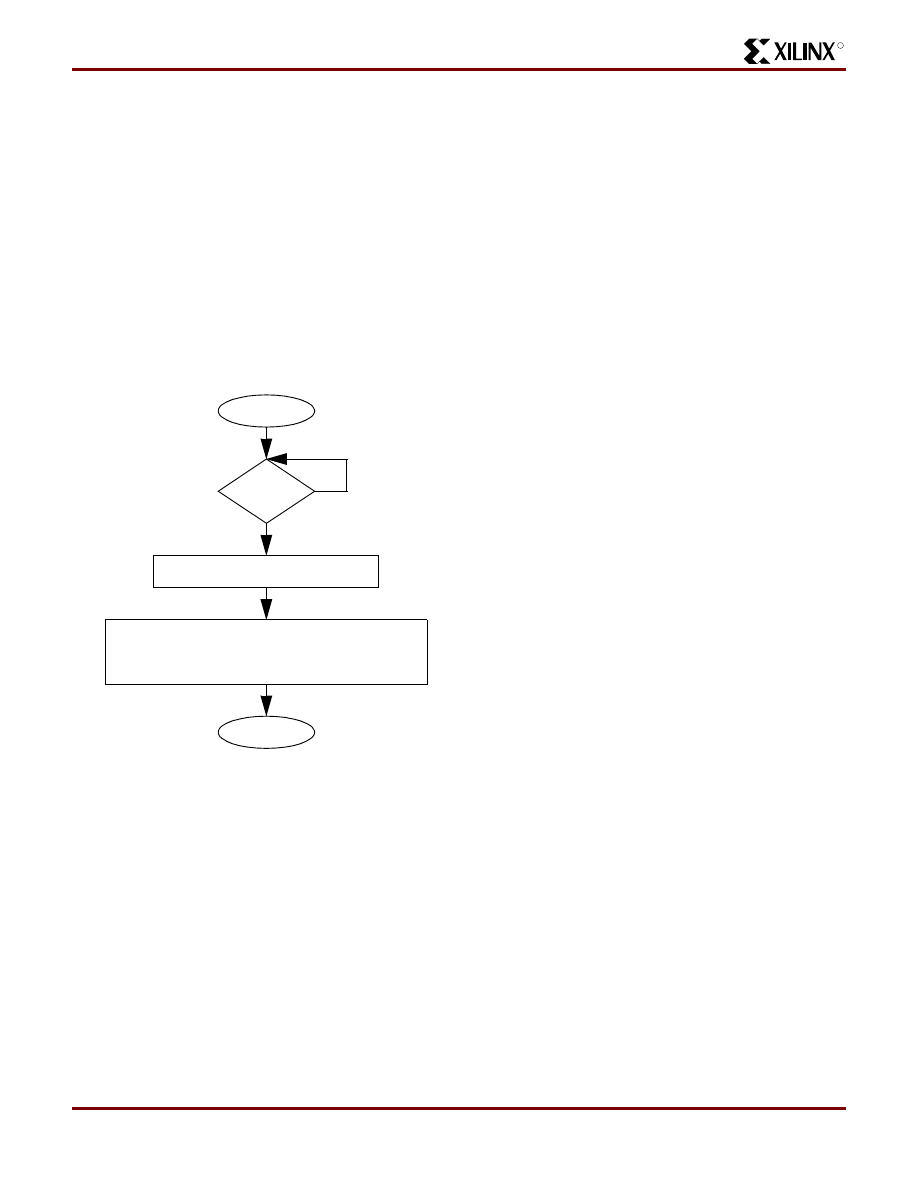
Rewind/Fast Forward
Rewind
If the user wants to skip to the start of the previous track,
the REW button is pressed.The previous track’s starting
address is loaded into the Song Flash address counter. At
this point, the MP3 portable player returns to its previous
state, i.e., if the MP3 Portable player was playing a song
when the REW button was pressed, Play operation begins.
If the MP3 portable player is currently playing the first song,
the REW operation simply starts the first song over again.
The song will not wrap around to the last song in the Song
Flash Memory. The REW operation is shown in
.
Figure 7: Rewind Operation
Fast Forward
The same operations executed for Rewind are done for
Fast Forward. When the FWD button is pressed, the next
track’s starting address is loaded into the Flash address
counter and the Play operation begins. The flow for the
Fast Forward operation is not shown as the only difference
between it and the Rewind operation is that the Track Num-
ber is incremented instead of decremented before reading
the data from the Starting Address Flash. Performing a Fast
Forward operation when the MP3 portable player is playing
the last song will cause the first song in the Song Flash
Memory to be played.
Volume Adjustments
The DAC 3550A provides analog volume control. It was
decided to control the volume of the MP3 portable player
via the DAC3550A analog controls for better mute and
low-volume sound quality. If these adjustments were made
in the MAS3507D in a digital format, the analog amplifier for
the headphones in the DAC3550A would be amplifying
mute and low-volume signals from the MAS3507D. This
could produce some noise during mute and low-volume
operation, making the sound not as clear as with the analog
controls provided with the DAC3550A.
START
END
Stop?
NO
YES
Disable MPEG Decoding and
WSEN = 0, PWMD = 1
put DAC in low power mode
Load Song Flash Address Counter with
Starting Address of Current Track
START
Decrement Track Number
Read Data from Starting Address Flash
Load Data into Song Flash Address Register
END
NO
YES
Rewind?
Disable MPEG Decoding
WSEN = 0, PWMD = 1
Put DAC in low power mode
R
Design of a MP3 Portable Player using a CoolRunner CPLD
XAPP328 (v1.1) December 31, 1999
www.xilinx.com
9
1-800-255-7778
The analog volume control of the DAC3550A is a 6-bit
value that covers a range from +18dB to -75 dB with the
lowest step being the mute position. Each increment or
decrement to this 6-bit value in the -75dB to -54dB range
represents a 3dB step. Each increment or decrement to this
6-bit value in the -54dB to +18dB range represents a 1.5dB
step. The default value is “101100” which represents 0dB.
Therefore, the value “101101” represents +1.5dB and
“101011” represents -1.5dB. A counter internal to the Cool-
Runner CPLD will maintain the volume value. This counter
is loaded with the volume default value (“101100”) at reset.
Adjustments to the volume of the song being played are
accomplished by the user pressing the volume “+” and “-”
buttons. Each press of these buttons increment and decre-
ment the volume counter and this value is then written to
the DAC3550A AVOL register. See
.
Figure 8: Volume Adjust Flow
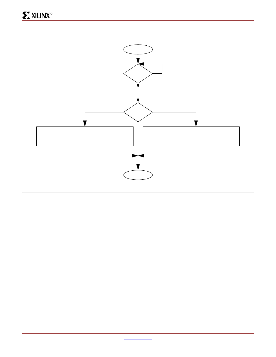
Mute
Pressing the MUTE button toggles the MP3 Portable player
mute control. The first press of this button mutes the output
of the player, the next press of this button turns mute off
and returns the volume to its previous level.
Mute is set in the DAC3550A by writing ‘0’ to the AVOL reg-
ister. When the MUTE button is pressed, the value of an
internal CPLD register is toggled. If the CPLD Mute register
is set, zeros are written to the DAC3550A AVOL register to
indicate the mute function. If the value of the CPLD Mute
register is ‘0’, then the value of the volume counter is writ-
START
Inc/Dec CPLD Volume Counter
END
Volume
NO
YES
Inc/Dec?
Write Volume Counter value to DAC3550A
AVOL register($C2) via I2C
Bits15,14,7,6 = ‘0’
Bit[13:8] = Left Volume Bit[5:0] = Right Volume
Design of a MP3 Portable Player using a CoolRunner CPLD
XAPP328 (v1.1) December 31, 1999
10
1-800-255-7778
R
ten to the DAC3550A AVOL register. This will return the
user to the previous volume level. (
)
Figure 9: Mute Operation
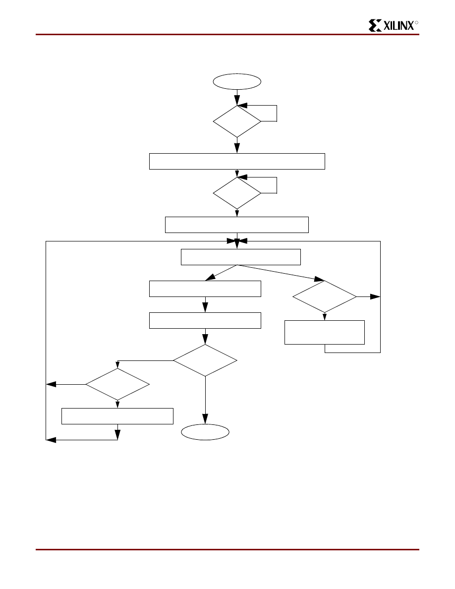
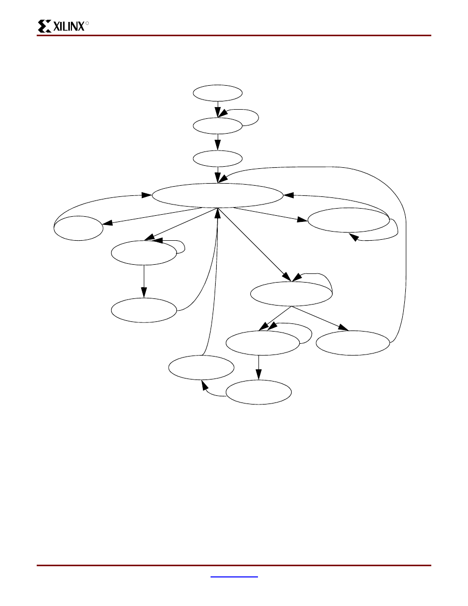
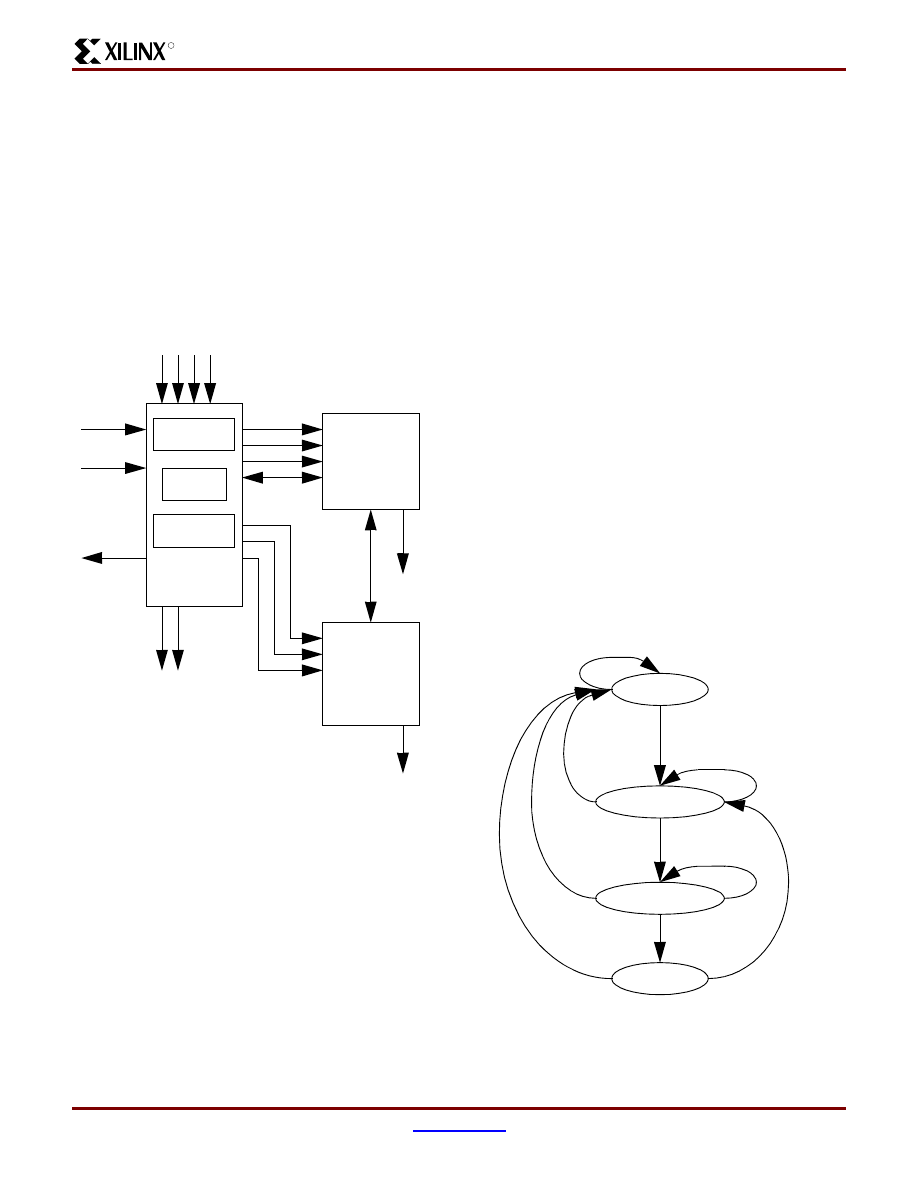
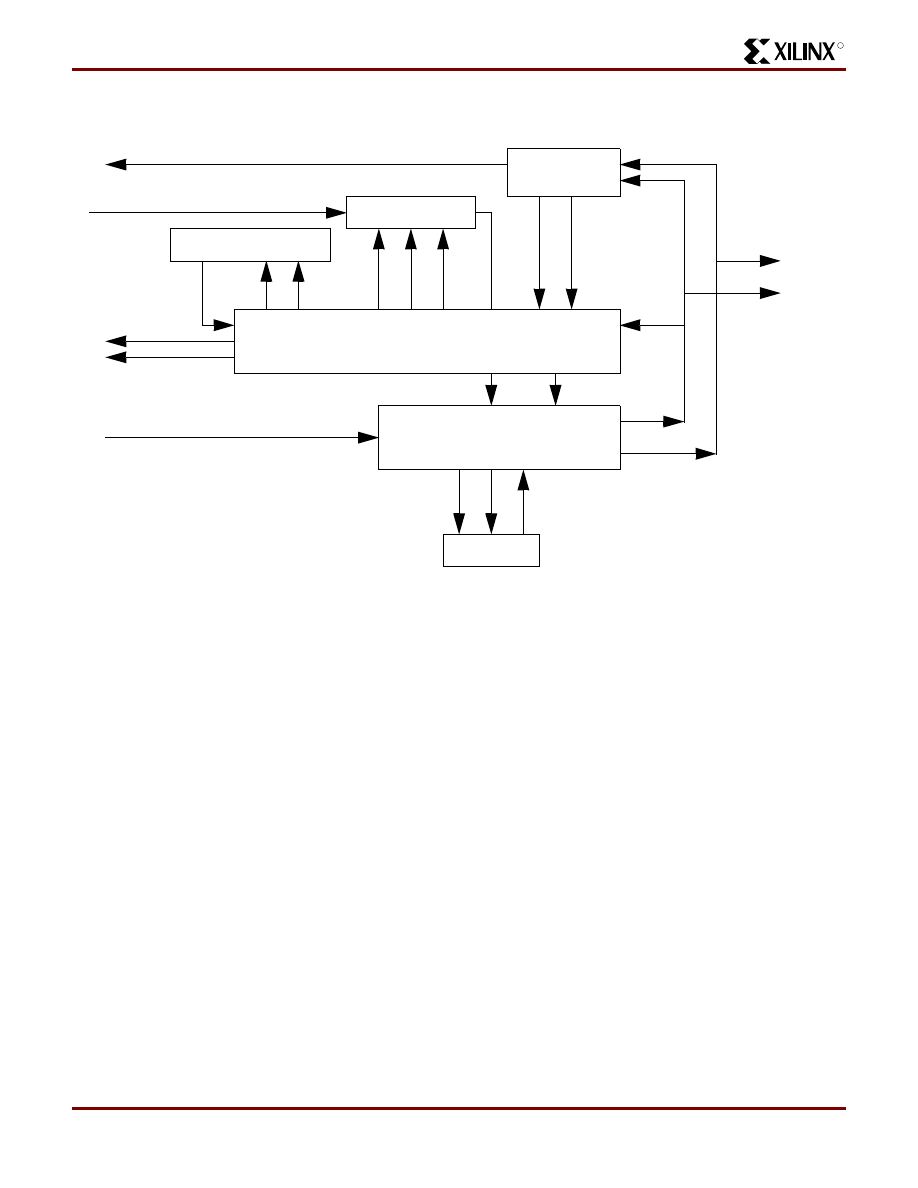
CoolRunner CPLD Main Control Logic
The Main Control Logic co-ordinates and prioritizes the
operations of the MP3 portable player and is shown in
. It consists of a Main controlling state machine
and other blocks of logic that control the more complex
functions such as the Play operation and the control of the
MPEG Chips (MAS3507D and DAC3550A). The Download
operation is performed in the Parallel Port Interface and the
operations for Rewind, Fast Forward, and Stop are per-
START
Toggle Internal Mute FF
END
Mute?
NO
YES
Write Volume Counter value to DAC3550A
AVOL register($C2) via I2C
Bits15,14,7,6 = ‘0’
Bit[13:8] = Left Volume Bit[5:0] = Right Volume
Mute FF = 1?
Write Zeros to DAC3550A
AVOL register($C2) via I2C
NO
YES
R
Design of a MP3 Portable Player using a CoolRunner CPLD
XAPP328 (v1.1) December 31, 1999
www.xilinx.com
11
1-800-255-7778
formed in the Flash Control Logic. The shaded block repre-
sents the CoolRunner CPLD Main Control Logic.
Figure 10: Main Control Logic Block Diagram
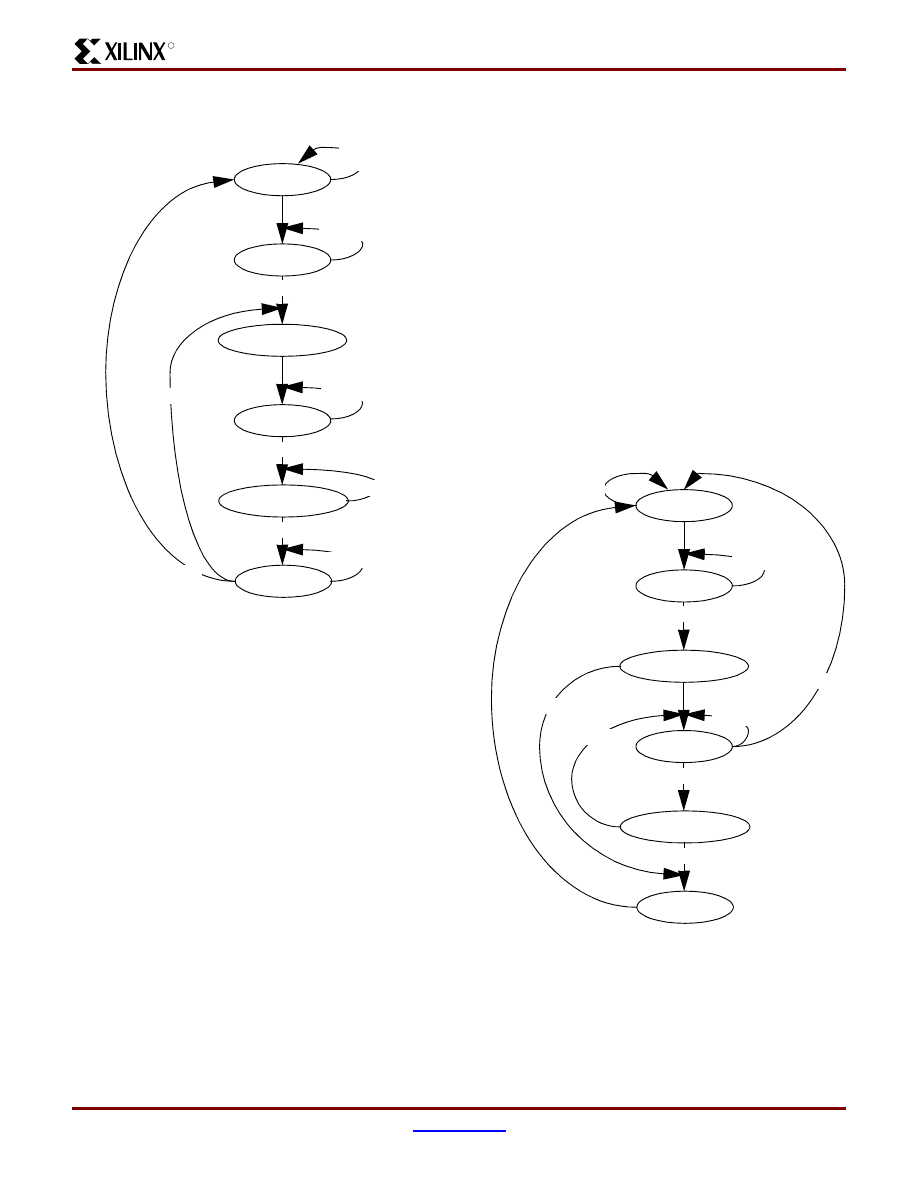
Main Control State Machine
The Main Control State Machine controls the prioritization
and ordering of functions. It provides the signals to the
other logic blocks for the more complex operations. The
state machine can be seen in
The Download function will always take priority over other
functions. When the download signal is asserted from the
Parallel Port Interface Logic, other operations are ignored
until the download operation is completed.
The PLAY operation is implemented in the PLAY Logic
block. The Main Control State Machine asserts Play to start
this logic and then returns to the state of looking for opera-
tions. If the operation is an adjustment to the sound (vol-
ume and mute), the play operation executes concurrently
with the sound adjustment operation. However, if the oper-
fu
ll_
fl
a
s
h
Parallel Port
Flash
User
Interface
MAS3507D
DAC3550A
Main Control State Machine
Play Logic
MPEG Chip
Control
dnld_mode
flash_done
rwd
fwd
stop
read
data[7:0]
nex
t
trs
_
rdy
data[7:0]
dnld_r
dy
track[4:0]
song_start,flash_done
c
m
d[1:0]
er
r
mpeg_
done
sd
a
scl
dnld_mode
display_err
play_stat[2:0]
vol_adj
mute_chg
Interface
Control
mute_stat
pr
eod
rt
r
wr
dy
ws
e
n
Pwr Mgmt
re
s
e
t
pwr
_dwn
of
f_ok
Starting
Addr
Flash
data,ctrl
data,ctrl
I2C Master Logic
i2c
_
e
rr
i2
c
d
[7:0]
st
a
rt
song_st
play
wakeup
play
vol_lvl[5:0]
Control
song_end
c
m
d_dat
eot
pup
Song
Flash
pup
ma
s
_
rs
t
crc_err
last_byte
upd_track
Design of a MP3 Portable Player using a CoolRunner CPLD
XAPP328 (v1.1) December 31, 1999
12
1-800-255-7778
R
ation is an adjustment to the song being played (stop,
rewind, fast forward), the play operation is stopped as the
play adjustment operation begins.
Figure 11: Main Control Logic - Main Control State Machine
Upon power-up, the Main Control State Machine must first
configure the data format mode of the DAC3550A to match
the data output of the MAS3507D. This is done in the
INIT_MPEG state. The appropriate command is encoded
on the CMD bus to the MPEG chip control logic. When this
command has been successfully executed, the state
machine moves to the LOW_PWR state to put the
DAC3550A into a low-power mode. The state machine then
moves to the IDLE state.
The IDLE state is the state where the state machine waits
for operations to occur. Signals from the Parallel Port Inter-
face Logic or the User Interface Control logic direct which
state is the next state.
The download operation takes precedence over all other
operations, therefore, once the download signal is
asserted, the state machine transitions to the DOWNLD
state and remains there until the download signal is
negated, indicating that the download operation has com-
pleted. All other signals are ignored while in the DOWNLD
state.
The user interface functions that affect the play functions
are encoded by the User Interface Control Logic on the bus
PLAY_STAT. (
See “Play Mode Logic” on page 27.
) If this
bus is set to PLAY, the state machine first enables the
MPEG chips by encoding the proper command on the CMD
bus to the MPEG Chip Control Logic and asserts the
WAKEUP signal to the Flash Control Logic. The state
DOWNLD
ENABLE_MPEG
ENABLE_PLAY
DISABLE_MPEG
FLASH_CTRL
RESET
INIT_MPEG
IDLE
mpeg_done=0
mpeg_done=1
downld_mode=1
downld_mode=0
play_stat=play
play_stat=stop,fwd,rwd
pwrdwn=1
vol_adj=1
mpeg_done=0
mpeg_done=0
mpeg_done=0
flash_done=0
flash_done=1
mpeg_done=1
mpeg_done=1
pwrdwn=1
mpeg_done=1
PWR_DWN
mpeg_done=1
play_stat=fwd,rwd,stop
mute_chg=1
DISABLE_MPEG
play=0
display_err=1
display_err=1
LOW_PWR
mpeg_done=1
WAIT_TRACK
UPDATE_TRACK
R
Design of a MP3 Portable Player using a CoolRunner CPLD
XAPP328 (v1.1) December 31, 1999
www.xilinx.com
13
1-800-255-7778
machine then transitions to the ENABLE_PLAY state to
assert the PLAY signal to activate the Play Logic. Once the
Play Logic is activated, the state machine returns to the
IDLE state to await other functions. Some functions will dis-
able the Play Logic, such as rewind, fast forward, and stop,
while others can operate concurrently with the Play Logic
such as volume adjustments and mute operations.
When the User Interface Logic detects a Stop, Rewind, or
Fast Forward, or the Power Management circuit issues a
Power-down, the state machine transitions to the
DISABLE_MPEG state. This state sets the CMD bus to the
proper command for the MPEG Chip Control logic and also
disables the Play Logic. If the function is a Power-down, the
state machine moves to the PWR_DWN state and asserts
the OFF_OK signal. This lets the Power Management
Logic know that it is now OK to shut off power. The state
machine leaves this state and returns to the IDLE state,
however, since power will be shut off, this is meaningless.
For the Stop, Rewind, and Fast Forward functions, the
state machine moves from the DISABLE_MPEG State to
the FLASH_CTRL state and activates the appropriate state
machines in the Flash Control Logic to perform the
selected function. Since these functions manipulate the
address counters for both the Song Flash and the Starting
Address Flash, this functions were implemented in the
Flash Control Logic. Once the functions have completed,
the FLASH_DONE signal asserts. The state machine then
transitions to the WAIT_TRACK to allow the track number
to be updated. The next state is the UPDATE_TRACK
states in which the LCD_CONTROL logic is instructed to
update the track number display. The state machine then
moves back to the IDLE state to await the next operation.
Note that the User Interface Logic keeps track of whether
the operation previous to the Rewind and Fast forward
functions was a Play operation. If so, it sets the
PLAY_STAT bus to the Play operation so that the Main
Control Logic state machine will again enable the Play
Logic.
If the operation is a volume adjustment or a mute, the state
machine moves to the SOUND_ADJ state. This state sets
the appropriate command on the CMD bus for the MPEG
Chip Control Logic to adjust the selected sound feature on
the MPEG chips. When these commands have been suc-
cessfully completed, the state machine returns to the IDLE
state.
Note that if either the MAS3507D or the MPEG Chip Con-
trol Logic asserts an error signal, the Main Control State
Machine will assert the ERR signal to the User Interface
Logic and return to the IDLE state.
Play Logic
The PLAY operation flow chart shown in
is imple-
mented by the Play Logic State Machine. It performs the
PIO-DMA transfer described in the MAS3507D-F10 data
sheet supplement. This transfer of parallel data is done in
16 byte segments using the PI19 - PI12 data pins and is
accomplished via the handshaking protocol described in
the MAS3507D-F10 data sheet supplement. Please refer to
the MAS3507D-F10 data sheet supplement from Intermet-
all for more detailed information.
The block diagram for the Play Logic is shown in
.
The Play Logic state machine holds the MAS3507D in reset
until a play operation begins. It asserts the read signal to
the Flash Control Logic when new data is needed for the
MAS3507D .
Figure 12: Play Logic Block Diagram
Play State Machine
The Play State Machine controls the generation of the
handshake signals require to perform the PIO-DMA data
Play State
Machine
mas_r
s
t
eod
read
s
ong_end
pr
TO/FROM FLASH CONTROL LOGIC
TO/FROM MAS3507D
play
rtr
wr
dy
Design of a MP3 Portable Player using a CoolRunner CPLD
XAPP328 (v1.1) December 31, 1999
14
1-800-255-7778
R
transfer mode of the MAS3507D. This state machine is
shown
.
Figure 13: Play Logic State Machine
The state machine starts in the IDLE state and moves to
the FLASH_DATA state when a play operation is enabled
and the EOD and WRDY signals from the MAS3507D are
asserted. If at any time, the play operation is disabled, indi-
cated by PLAY=0, this state machine will complete the cur-
rent handshake cycle so that the last data word is correctly
written to the MAS3507D before returning to the IDLE
state.
The FLASH_DATA state asserts the READ signal to the
Flash Control Logic. This signal remains asserted until the
data has been loaded into the MAS3507D. This Flash Con-
trol Logic will not obtain new data from the Flash until Read
is negated. After asserting the READ signal, the state
machine transitions to the ASSERT_PR state.
The ASSERT_PR state asserts the PR signal to the
MAS3507D indicating that valid data is present on the
PI19-PI12 pins. The state machine stays in this state until
the MAS3507D asserts the RTR signal indicating that it is
obtaining the data. The state machine then transitions to
the WAIT_RTR state. The state machine stays in the
WAIT_RTR state until RTR is again negated indicating that
the MAS3507D has latched the data.
The state machine then transitions to the NEGATE_PR
state where it negates both the PR and READ signals. The
negation of the READ signal advances the Flash Control
Logic Read state machine so that the address to the Song
Flash is incremented and the next data byte becomes avail-
able. The state machine then moves to the IDLE state to
perform the next byte transfer.
When the end of MP3 data in the Flash has been detected
by the Flash Control Logic, the SONG_END signal is
asserted. This signal is sampled in the IDLE state when the
current byte transfer to the MAS3507D has been com-
pleted.
MPEG Chip Control
The MPEG Chip control logic performs the sequence of I2C
commands necessary to write registers in the DAC3550A
chip. The three I2C functions required to control the
DAC3550A chip are:
1. Write to DAC3550A AVOL register(16 bits)
2. Write to DAC3550A GCFG register (8 bits)
3. Write to DAC3550A SR_REG register(8 bits)
Note that the I2C required functions are write-only, no I2C
read functions are required. The command to write a regis-
ter in the DAC3550A is shown in the section
Basic operation of the MAS3507D is possible without con-
figuration over the I2C bus. Configuration and the most
important status information are available using the PIO
interface of the MAS3507D. The basic operation of the
MAS3507D will be used for this application and therefore
the MAS3507D will be configured using the PIO interface.
MAS3507D Parallel Input Output Interface (PIO)
The parallel interface of the MAS3507D consists of the
lines PI0-PI4, PI8, PI12-PI19, and several control lines.
During start-up, the PIO will read the start-up configuration
to define the environment for the MAS3507D. These pins
must be connected via resistors to GND or VDD.
shows the connections of these pins for the CoolRunner
MP3 portable player. Note that pins PI12-PI19 are used for
the parallel MP3 data. Please see the MAS3507D data
sheet and the MAS3507D-F10 data sheet supplement from
Intermetall for more information.
IDLE
FLASH_DATA
ASSERT_PR
NEGATE_PR
WAIT_RTR
rst or
play=0,wrdy=0,eod=0
play=1,wrdy=1,eod=1
rtr=1
rtr=0
rtr=1
rtr=0
MAS3507D PIO
Pin
Value at
Power-up
Definition
PI8
0
Divide CLK0 by 1,
2, or 4 (according
to MPEG 1,2, or
2.5)
PI4
1
PIO DMA input
mode
PI3
0
Enable layer 3
PI2
0
Enable layer 2
PI1
0
32-bit SDO output
PI0
0
Multimedia mode
Table 1: MAS3507D PIO Pin Startup Configurations
R
Design of a MP3 Portable Player using a CoolRunner CPLD
XAPP328 (v1.1) December 31, 1999
www.xilinx.com
15
1-800-255-7778
DAC3550A I2C Interface
The DAC3550A Write Register Command is shown in
Figure 14: DAC3550A Write Register Command
The subaddresses for the DAC3550A registers are shown
in
Table 2: DAC3550A Register Subadddresses
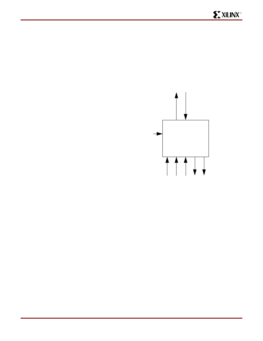
MPEG Chip Control Block Diagram
The MPEG Chip control logic interfaces to the Main Control
State Machine and the I2C Master logic. Its function is to
implement the three I2C required operations. The I2C com-
mands are encoded on the CMD[1:0] bus as shown in
. Note that CMD[1:0] is set to zero to indicate that no
I2C command is required. When the indicated operation
has completed without errors, the DONE line is asserted. If
an error occurs in the I2C transaction, the ERR line is
asserted.
Table 3: I2C Command Encoding
The MPEG Chip Control Logic consists of a state machine
that sets the start bit, paces the writing of data to the I2C
Master logic when transactions are complete, and then
ends the command. Data is sent to the I2C Master Logic
over the I2CD[7:0] bus. The source of the I2C data is deter-
mined by the command being implemented. The data can
be either be specific command constants defined by the
chip command protocol, the value of the Volume Counter,
or all zeros if the Mute FF is ‘1’.
The START signal is asserted to force an I2C Start condi-
tion and is negated to force an I2C Stop condition. At the
end of each byte transfer, the I2C Master Logic asserts the
EOT signal and the MPEG Chip Control logic writes the
next data byte to be transmitted over the I2C bus. If an
acknowledge is not received for an I2C transfer, the I2C
Master Logic sets the ERR bit indicating an error in the I2C
bus transfer. (
Figure 15: MPEG Chip Control Block Diagram
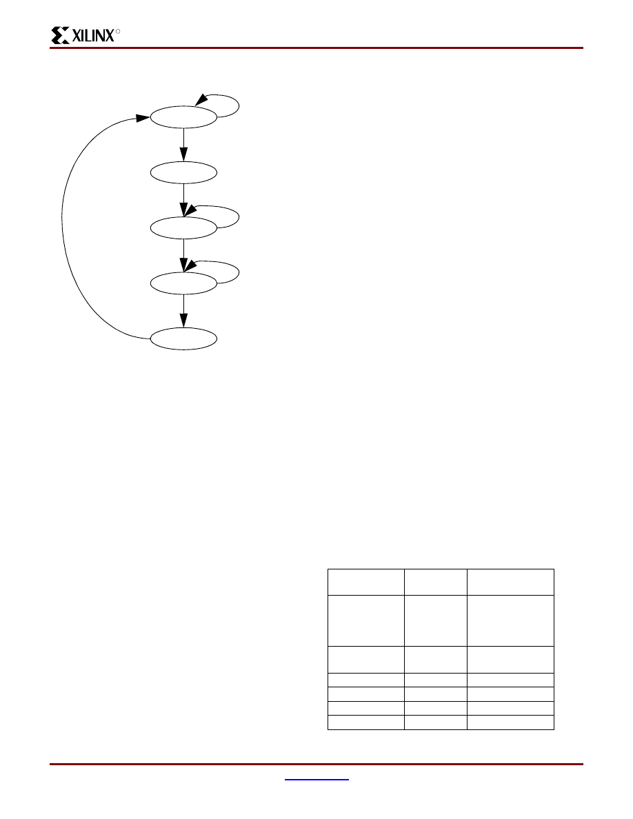
MPEG Chip Control State Machine
Since the Write Register command to the DAC3550A chip
contains several sequences of data writes, a state machine
is used to implement these commands. Based on the value
of the CMD bus, the state machine will determine the data
to be output to the I2C Master Logic and the number of data
transactions required. This state machine is shown in
Figure 16: MPEG Chip Control State Machine
The MPEG Chip Control State Machine will stay in the IDLE
state while the CMD bus indicates that there is no I2C com-
Register
Subaddress
Size
SR_REG
$C1
8 bits
AVOL
$C2
16 bits
GCFG
$C3
8 bits
CMD[1:0]
Operation
0
Nothing
1
Write DAC3550A SR_REG reg
2
Write DAC3550A AVOL reg
3
Write DAC3550A GCFG reg
S devwrite A subaddr
databyte
P
A
A
S devwrite A subaddr
databyte
P
A
A
databyte A
S = Start
devwrite = $9A
A = Ack
P = Stop
8-bit write
16-bit write
cmd[1:0]
err
i2cd[7:0]
start
eot
mpeg_done
clk,rst
rst
scl
sda
Mute
FF
Volume
Counter
MPEG Chip Control
State
Machine
clk
i2c_err
I2C
Master
Logic
I2C Dat
a
Regis
ter
cmd_dat
mute_stat
detect_stop
IDLE
HEADER
SUBADDR
DATA_1
rst
cmd=0
cmd=1,2,3
eot= 0
eot= 1
DATA_2
eot= 1
eot= 0
eot= 0
eot= 0
eot= 1
cmd=2
cmd<>2
eot= 1
DONE
eot= 1
WAIT_STOP
detect_stop=1
Design of a MP3 Portable Player using a CoolRunner CPLD
XAPP328 (v1.1) December 31, 1999
16
1-800-255-7778
R
mand to be transmitted (CMD= 0). In this state, the START
signal is negated. The state machine transitions to the
HEADER state when the CMD bus indicates that there is
an I2C command.
In the HEADER state, the MSB of the CMD bus determines
which I2C header is written to the I2C Data Register in the
I2C Master Logic. Once the correct header is written to this
register, the START signal is asserted. A rising edge of the
START signal instructs the I2C Master Logic to generate a
START condition and transmit the data in the I2C Data
Register. The state machine stays in this state until the
EOT signal is asserted, indicating that the header has been
successfully transmitted on the I2C bus. Once EOT has
been asserted, the state machine transitions to the SUB-
ADDR state and writes the correct subaddress in the I2C
data register. The state machine stays in this state until
EOT is asserted, indicating that the subaddress has been
successfully transmitted on the I2C bus.
In the DATA_1 state, the next data word in the selected
command is written to the I2C data register and the state
machines waits for the EOT signal to be asserted from the
I2C Master Logic. If the selected command is to write to the
AVOL register which is 16 bits, the state machine transi-
tions to the DATA_2 state to write the last data byte to the
I2C data register. Otherwise, this data byte was the last
data of the command and the state machine transitions to
the WAIT_STOP state once EOT is asserted.
In the DATA_2 state as in the DATA_1 state, the state
machine waits for the assertion of EOT and returns to the
WAIT_STOP state once EOT has been asserted.
Note that the START signal is negated in the WAIT_STOP
state, therefore, transitioning to the WAIT_STOP state
causes a falling edge of the START signal which instructs
the I2C Master logic to create a STOP condition and the
I2C command is completed. The state machine leaves the
WAIT_STOP state when the DETECT_STOP signal is
asserted, indicating that the I2C logic has implemented and
detected the stop condition.
At this point, the state machine transitions to the DONE
state which asserts the MPEG_DONE signal.
No handshaking is required indicating that valid data has
been written into the I2C data register. This is due to the
fact that the MPEG chip control state machine is running off
the system clock (2MHz) and the I2C Master Logic main
state machine is running off SCL (400KHz), therefore, the
MPEG chip control state machine has several clock cycles
from the assertion of EOT to update the data in the I2C data
register. The I2C Master logic Main State Machine simply
assumes that the I2C data register contains the data to be
transmitted on the I2C bus and has been updated.
Since EOT is generated by the I2C Master Logic, it is
clocked by SCL and is therefore asserted from several sys-
tem clocks. Therefore, the MPEG Chip Control Logic
detects the rising edge of EOT and this rising edge is used
to transition the state machine between states.
If at any point, the I2C Master Logic asserts the ERR signal
indicating that an acknowledge was not received, the state
machine asserts the ERR signal to the Main Control Logic
State Machine and returns to the IDLE state.
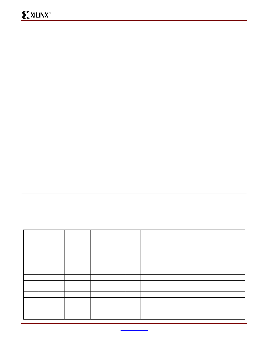
CoolRunner CPLD Parallel Port Interface
The download software will download MP3 data to the MP3
portable player via the PC parallel port. The bits of the par-
allel port are defined as shown in
will have weak pull-ups on each of the parallel port connec-
tions. Connection to the PC can then be determined by a
logic ‘0’ on pins 18 - 25. The connection to the PC must be
verified before operating on any of the other signals from
the parallel port.
Pin
PC
Definition
MP3 Player
Definition
Direction
Active
Level
Description
1
nStrobe
nStrobe
PC - MP3 Player
Low
Strobe - this signal indicates that the data on the data
pins is valid.
2 - 9
Data[0:7]
Data[0:7]
PC- MP3 Player
N/A
MP3 Data
10
nAck
nAck
MP3 Player - PC
Low
Acknowledge - this signal indicates that the MP3 Player
has received the data on the data pins and is ready for
the next data word
11
Busy
Dld_Rdy
MP3 Player - PC
High
MP3 Player is ready to begin download function
12
PError
Last_Byte
PC-MP3 Player
High
Last Byte of MP3 Data - This bit is asserted when the
download data is the last byte of MP3 data.
13
Select
Not Used
14
nAutoFd
Song_st
PC - MP3 Player
High
This bit is asserted when the download data is the begin-
ning of a song. The MP3 player uses this bit to store the
current address of the Song Flash into the Starting Ad-
dress Flash.
R
Design of a MP3 Portable Player using a CoolRunner CPLD
XAPP328 (v1.1) December 31, 1999
www.xilinx.com
17
1-800-255-7778
Table 4: Parallel Port Pin Definitions
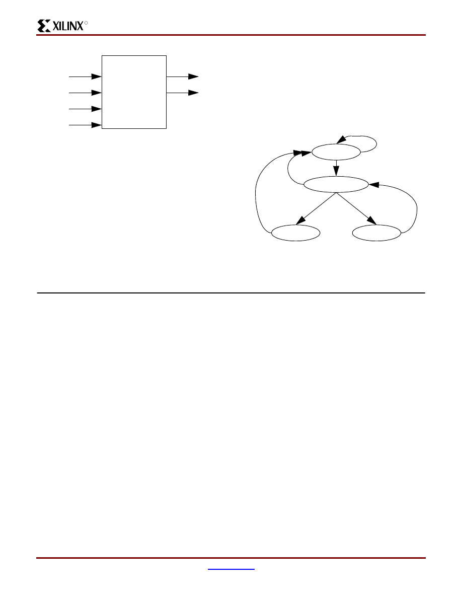
The Parallel Port logic implements the download operation
shown in
. This logic communicates directly with
the Flash Control Logic during the download process. A
download signal is sent to the Main Control Logic and the
User Interface Logic. All other operations are ignored while
the download operation is taking place. The interface sig-
nals for the Parallel Port logic are shown in
. The
data bus, DATA[7:0], the SONG_ST signal, and the
LAST_BYTE signal connect directly to the Flash Control
Logic.
Figure 17: Parallel Port Logic Interfaces
The signals interfacing to the Parallel Port on the PC are
described in
. The signals to the Flash Control and
Main Control Logic are for handshaking during the Down-
load process and for error reporting.
When the download operation begins, the Parallel Port
Logic asserts the DNLD_MODE signal to the rest of the
CPLD logic to indicate that a download is taking place. The
DNLD_RDY signal states that the Flash erase operation
has completed and the Flash is ready to accept data for
download. The NEXT signal is input to the Parallel Port
Logic indicating that the Flash Control Logic is ready for the
next piece of data to write to the Flash. TRS_RDY is
asserted by the Parallel Port Logic to indicate to the Flash
that the data from the parallel port is valid data.
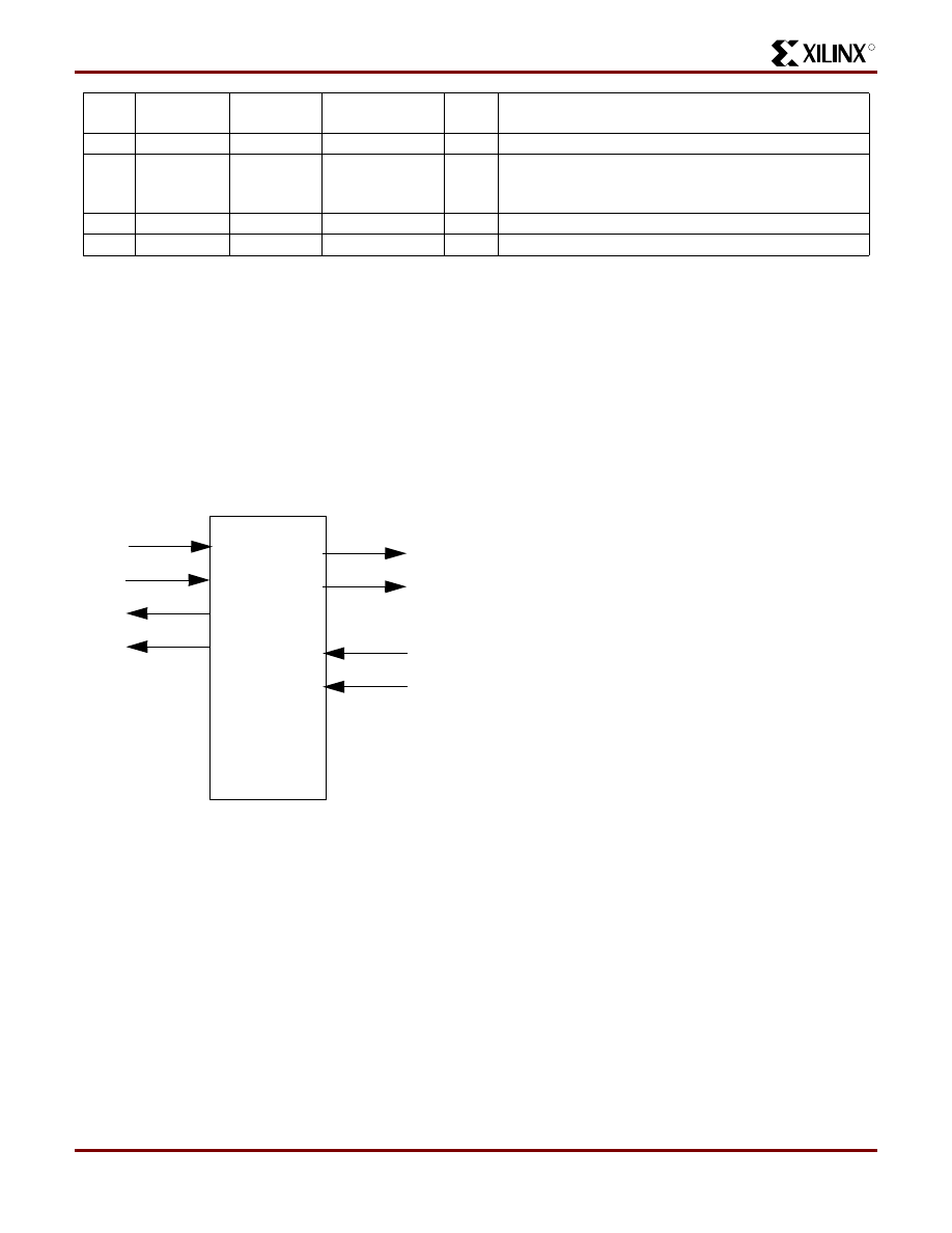
The Parallel Port logic consists of a state machine that
handshakes data with the parallel port and controls the
Flash download operation. This state machine is shown in
. Pins 18-25 on the parallel port are connected to
GND when the MP3 portable player is connected to the PC.
Therefore, these pins are checked for GND and the
DOWNLD signal must be asserted before the state
machine transitions from the IDLE state to the
DNLD_MODE state.
The DNLD_MODE state asserts the DNLD_MODE signal
to the rest of the CPLD logic indicating that the download
operation has begun. The state machine waits for the Flash
Control Logic to assert the DNLD_RDY signal indicating
that the Flash is ready to accept data and then transitions
to the DLD_RDY state.
The DLD_RDY state asserts the DLD_RDY signal to the
PC indicating that the MP3 portable player is ready for a
download. The state machine remains in this state until the
PC asserts the NSTROBE signal indicating that valid data
is on the DATA[7:0] pins.
Once NSTROBE is asserted, the state machine transitions
to the TRS_RDY state and asserts the TRS_RDY signal to
the Flash so that the Flash knows the data is valid. The
state machine remains in this state until the NEXT signal is
asserted from the Flash indicating that the data has been
written and the Flash is ready for the next data word.
When NEXT is asserted, the state machine transitions to
the ACK state where the nACK signal to the PC is asserted.
The PC can then negate nSTROBE and the state machine
transitions to the DLD_RDY state. The PC then places the
next data byte on the DATA[7:0] pins and asserts
nSTROBE.
This process continues until the PC has written all of the
data to the MP3 portable player. Once all of the data has
been downloaded, the PC negates DOWNLD and the state
machine returns to the IDLE state.
15
nFault
Not Used
16
nInit
Downld
PC- MP3 Player
High
PC is ready to begin download function. Download func-
tion will begin when the MP3 Player asserts the Dld_rdy
signal.
17
nSelectIn
Not Used
18 - 25
GND
GND
N/A
N/A
Signal Ground
Pin
PC
Definition
MP3 Player
Definition
Direction
Active
Level
Description
nStrobe
downld
nAck
dld_rdy
next
dnld_rdy
trs_rdy
dnld_mode
Parallel Port
Logic
PC Parall
el Por
t
F
las
h Contr
o
l and
M
a
in
C
ontrol Logic
Design of a MP3 Portable Player using a CoolRunner CPLD
XAPP328 (v1.1) December 31, 1999
18
1-800-255-7778
R
Figure 18: Parallel Port State Machine
CoolRunner CPLD Flash Control Logic
The Flash Control Logic module not only controls the Song
Flash and Starting Address Flash memories, but controls
the addresses of these flash memories when performing
Rewind, Fast Forward, and Stop operations. In addition,
this module is responsible for recognizing when a new
song has started during the Play operation and when the
end of MP3 data in the Song Flash has been reached.
The Flash Control Logic is broken down into separate enti-
ties as shown in
. The Download Interface Logic
block handles the handshaking interface with the Parallel
Port logic for a download operation. The User Command
logic contains the state machines to implement the Rewind
(REW), Fast Forward (FWD), and Stop operations. The
Song Flash and Starting Address Flash Control block is
responsible for writing data, erasing data, and reading data
from the Flash memories as well as incrementing, decre-
menting, and resetting the address counters. This block
also contains the logic that compares the current Song
Flash address during a Play operation with the Starting
Address for the current track number to determine if the
data from the Song Flash is the beginning of a new song. It
controls the assertion of the SONG_START signal during a
Play operation that updates the LCD display. This logic also
recognizes the last address of MP3 data in the Song Flash
and asserts the SONG_END signal so that the address
counters can reset and the playing of music can continue
from the beginning of the downloaded data.
Since the Song Address is 25 bits and the Starting Address
Flash is 16 bits wide, two cycles are required to read or
write the Song Flash address into the Starting Address
Flash. The least significant bit of the track number indicates
which cycle is being implemented - the cycle that
writes/reads the upper bits of the Song Flash address or
the cycle that writes/reads the lower bits of the Song Flash
address. Note that the upper bits of the Song Flash address
are stored in even locations in the Starting Address Flash
and the lower bits are stored in odd locations. For example,
bits 25 - 16 of the starting address for track 4 are stored at
location 6 of the Starting Address Flash and bits 15-0 are
stored at location 7.
Since there are 7 unused bits in the Starting Address Flash
when storing the 25-bit Song Flash address, the last
address of the MP3 data in the Flash sets the most signifi-
cant bit to ‘1’. This is used as the flag to indicate that the
last of the MP3 data has been read from the Song Flash.
IDLE
DNLD_MODE
DLD_RDY
TRS_RDY
ACK
rst
pins18-25=1
pins18-25=0
downld=1
dnld_rdy=1
nstrobe=0
dnld_rdy=0
nstrobe=1
next=1
next=0
downld=0
nstrobe=1
downld=0
R
Design of a MP3 Portable Player using a CoolRunner CPLD
XAPP328 (v1.1) December 31, 1999
www.xilinx.com
19
1-800-255-7778
Figure 19: Flash Control Logic Block Diagram
Download
Interface
Song
Flas
h
Addr
Counter
S
tarting Addr
Flas
h
Addr C
ounter
Song Flash
User Command
Logic
Detect
32Mbyte
Song
8Mbit
Starting Addr
Song
Start
dnld_mode
trs_rdy
song_st
dnld_rdy
next
w
a
k
eup
pl
ay
rea
d
re
w
fwd
st
o
p
flash_done
da
ta
[7:
0
]
track[4:0]
song_start
s
o
n
g_a
dr
[2
4:
0]
data[7:0]
data[7:0]
start_adr[15:0]
song_adr[24:0]
st
ar
t_a
d
r[
15:0
]
song_end
Flash
and
Starting Address
Flash Control
Flash
so
ng
_w
r
s
o
ng
_e
n
s
o
n
g_o
ut
s
tad
r_
en
stad
r_
o
u
t
stad
r_
w
r
Logic
last_byte
Design of a MP3 Portable Player using a CoolRunner CPLD
XAPP328 (v1.1) December 31, 1999
20
1-800-255-7778
R
Download Interface Logic
The Download Interface Logic block is responsible for the
handshaking interface to the parallel port during a down-
load operation (
).
Figure 20: Download Logic Block Diagram
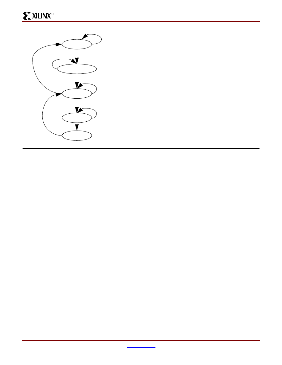
Download Control State Machine
The Download Control State machine waits for the
DNLD_MODE signal to be asserted, at which time both
flash blocks are erased. The flash memories are erased in
128 KByte blocks. All 128 blocks of the Song Flash mem-
ory are erased, however, due to the large size of the blocks,
it is only necessary to erase the first block of the Starting
Address Flash.
After a successful erase, the DLD_RDY signal is sent back
to the parallel port. Once TRS_RDY is asserted by the Par-
allel Port Logic, data is present on the data lines. If the
SONG_ST bit is asserted, the address of the Song Address
Flash is written to the Starting Address Flash. Note that the
address of the Song Flash is 25 bits, therefore this must be
written in 2 write cycles to the Starting Address Flash. The
END_WRITE_ERS signal will assert when both of the write
cycles to the Starting Address Flash have been success-
fully completed. The MP3 data byte is then written to Song
Flash memory at the corresponding address and the
address is then incremented.
If the DNLD_MODE line is still asserted, the NEXT signal is
asserted to get the next byte of data. The last byte of MP3
data is marked by the assertion of the LAST_BYTE signal.
When this signal asserts, the address of the Song Flash is
written to the Starting Address Flash as the ending address
of MP3 data. The last address of the MP3 data is written
into the Starting Address Flash with the most-significant bit
set to ‘1’ to flag this as the end of the MP3 data. (
Figure 21: Download Control State Machine
This state machines indicates the required function to the
FLASH_CNTR logic via the bus, FLASH_CMD. This bus is
encoded as shown in
User Command Logic
The User Command Logic Block is responsible for detect-
ing and implementing the user commands and correctly
controlling the addresses and address counters for the
dnld_mode
trs_rdy
song_st
end_w
rite_ers
dnld_rdy
next
Download
Control
last_byte
flas
h_c
md[
2
:0]
FLASH_CMD
Operation
000 - 011
Do Nothing
100
Write Song Flash
101
Erase Song Flash
110
Erase Starting Address
Flash
111
Write Starting Address
Flash
Table 5: Flash Command Bus Encoding
IDLE
F_ERASE
DNLD_RDY
WRITE
NEXT
rst
dnld_mode=1
end_write_ers=1
trs_rdy=1
end_write_ers=0
trs_rdy=0
last_byte=1 or
dnld_mode=0
end_write_ers=0
end_write_ers=1
WRITE_STADR
end_write_ers=0
ST_ERASE
end_write_ers=1
WRITE_WAIT
song_st=0
song_st=1 and
trs_rdy=1
end_write_ers=1
dnld_mode=0
song_st=1
R
Design of a MP3 Portable Player using a CoolRunner CPLD
XAPP328 (v1.1) December 31, 1999
www.xilinx.com
21
1-800-255-7778
Flash memories. The commands REW, FWD, and STOP
all change the current memory location and song track.
(
)
Figure 22: User Command Logic Interfaces
Command State Machine
The command state machine implements the operations to
the flash address counters as required by the rewind
(REW), fast forward (FWD), and stop (STOP) operations
and is shown in
.
The REW and FWD cause the MP3 Player to either skip to
the previous song or skip forward to the next song. This is
accomplished by incrementing or decrementing the track
number, reading the starting address for that track number
from the Starting Address Flash and loading that address
into the address counter for the Song Flash. Note, how-
ever, that the track number is always pointing to the next
song to be played, therefore the track number is first
adjusted to point to the current track. This is accomplished
in the CHK_TRACK, DEC1, and DEC2 states.
In the TRACK_NUM state, the track number has been
adjusted to point to the upper bits of the starting address of
the current track number. This state either increments the
track number for a fast forward, or decrements the track
number for a rewind. The track number will not decrement
below zero, therefore, rewinds past the first song result in
the first song being played. If the increment of the track
number reaches the end of the MP3 data, the
CMD_SONG_END signal is asserted and both address
counters are reset. Therefore, fast forwards past the last
song will result in the first song being played. Since the
Song Flash address is 25 bits, it is stored as 2 16-bit words
in the Starting Address Flash and there requires 2
read/load cycles.
The least-significant bit of the track number indicates which
read/load cycle is being executed. Therefore, wait states
are necessary so that either the increment or the decre-
ment operation are completed before the track number is
examined.
Note that the MAS3507D chip is disabled during this oper-
ation, therefore, if a CRC error from the MP3 chip is caused
by the fact that a previous frame of MP3 data to this chip
may be incomplete, this error should be reset while the chip
is disabled. Once the address counters have been set for
the REW or FWD operation, the FLASH_DONE signal is
asserted to allow the Main Control Logic to implement the
next operation.
The STOP operation requires that the Song Flash address
counter be loaded with the starting address of the current
track number. The starting address of the current track is
read from the Starting Address Flash and loaded into the
Song Flash address counter. The FLASH_DONE signal is
then asserted.
The SONG_END signal from the Detect Song Start Logic
will simply reset the address counters for both Flash Mem-
ories.
Figure 23: Command State Machine
User Command Logic
fwd
rew
stop
flash_done
data[7:0]
re
ad
_s
ta
dr
Command
State
Machine
cmd_song_end
stad
r_
in
c
stad
r_
d
e
c
ad
r_
ld
_
l
ad
r_
ld
_
u
start_address[15:0]
track[4:0]
IDLE
TRACK_NUM
READ_ADDR
rst
rwd,fwd,stop=1
rwd,fwd,stop=0
LOAD_ADDR
DONE
lsb=1 or
lsb=0
CHK_TRACK
DEC1
DEC2
WAIT_DEC
WAIT_TRACK
WAIT_ADDR
WAIT_RDINC
cmd_song_end=1
cmd_song_end = 0
Design of a MP3 Portable Player using a CoolRunner CPLD
XAPP328 (v1.1) December 31, 1999
22
1-800-255-7778
R
Song Flash and Starting Address Flash
Control
The Song Flash and Starting Address Flash Control Logic
manage the command signals to the flash memories for
reading, writing, and erasing. The control lines to enable,
write, and read from the flash memories are generated at
the appropriate times depending on the chosen operation.
This logic also controls the Song Flash and Starting
Address Flash address counters.
This block consists of two state machines which perform
the Read, Write, and Erase functions to the flash memo-
ries. The block diagram for the Song Flash and Starting
Address Flash Control is shown in
Figure 24: Song Flash Control Block Diagram
Read State Machine
While in operation, the flash memories consume active
power. Both flash memories only need to be active during
certain operations. When the memory blocks are not
enabled during these times, they enter standby mode. This
is controlled by asserting and negating the chip enable sig-
nal. On a portable MP3 player where power consumption
must be limited, this control minimizes memory power and
system power consumption.
After a download operation, the Flash memories are set in
Read mode. The Song Flash memory is only being read
during the Play operation, therefore the Song Flash mem-
ory is put into standby mode for all other operations (except
Download). To activate the Song Flash, the Song Flash CE
is asserted by the WAKEUP signal from the Main Control
Logic before the Play operation begins.
The Starting Address Flash is read for Play, Rewind, Fast
Forward and Stop operations. For these operations, the
Starting Address Flash is taken out of standby mode.
The Read State machine shown in
is replicated
to read data from both the Song Flash and the Starting
Address Flash. It transitions from the IDLE state to the
ENABLE_RD state when the DNLD_MODE signal is
negated and the correct operations are enabled that
require the Flash to be removed from Standby mode. For
the Song Flash, this is just the WAKEUP signal, for the
Starting Address Flash, this is the WAKEUP, REW, FWD,
PLAY, or STOP signals. The ENABLE_RD state asserts the
CE and the OE signals to the flash to remove the flash from
Standby Mode. At this point, the data from the current
address is available on the Flash data output pins. If the
READ signal is asserted, the state machine moves to the
READ_DATA state. The READ signal will remain asserted
while the data is current Flash data is being utilized. When
this data no longer is needed, the READ signal is negated.
Once the READ signal is negated, the state machine tran-
sitions to the INC_ADDR state where the address counter
is incremented. The next state is then the ENABLE_READ
state.
If at any point, the DNLD_MODE signal asserts indicating
that a download operation is starting, this state machine
returns to the IDLE state so that the Write/Erase State
Machine can control the Flash memories.
Figure 25: Read_Song and Read_Stadr State
Machines
flash_cmd[2:0]
end_write_ers
ad
dr
c
n
t_
c
tr
l
song_out
song_wr
data[7:0]
Read_Song
Write
Song Flash
oe#
we#
dq[7:0]
so
ng
_ad
dr
[2
4:
0]
STS
song_en
ce
Song Flash &
Erase
oe#
we#
dq[15:
0
]
ce
Starting
Starting Addr
Flash Ctrl
Addr
Flash
st
ad
dr
cn
t_
c
tr
l
re
a
d
re
ad
_st
a
dr
st
ad
r_
e
n
stad
r_
o
u
t
st
ad
r_
wr
Read_Stadr
wakeup
STS
ad
r_
ld
_
l
ad
r_
ld
_
u
IDLE
ENABLE_READ
rst
dnld_mode=0
read=1
dnld_mode=1
dnld_mode=1
read=0
dnld_mode=0
INC_ADDR
READ_DATA
read=1
read=0
wakeup=1
rew,fwd, play,stop =1
dnld_mode=1
dnld_mode=1
R
Design of a MP3 Portable Player using a CoolRunner CPLD
XAPP328 (v1.1) December 31, 1999
www.xilinx.com
23
1-800-255-7778
Write/Erase State Machine
The Write and Erase operations for the Song Flash and the
Starting Address Flash are very similar and are combined
into one state machine as shown in
.
The Write operation is performed byte-by-byte during
download mode. The write operation requires that a
WRITE command first be written to the flash followed by
the actual data write. The command is first written and then
the data to the specified address. Once the STS signal is
asserted indicating that the Flash has completed the oper-
ation, the address counter is incremented. The
END_WRITE_ERS signal is asserted to complete the write
byte cycle.
Erasing the Flash memories is performed on a 128KByte
block. The Erase operation, like the Write operation, first
requires that an ERASE command be written to the flash
with the address of the block to be erased followed by a
write cycle with a CONFIRM data word. When in ERASE
mode for the Song Flash, the state machine will loop
through all 128 blocks and erase each one. The STS signal
from the Flash indicates when each block erase has been
completed. Indexing into each block is accomplished by
presetting the lower bits of the address counter so that the
address counter, when incremented, contains the next
block address. When the terminal count of the counter has
been reached, all blocks have been erased and the erase
operation is complete. The address counter to the Flash is
then cleared and the END_WRITE_ERS signal is asserted.
Note that since only one block of the Starting Address
Flash will ever be used, only the first block is erased.
For simplicity, the state machine diagram shown in
does not indicate all signals used in the next
state decisions. Only the flows for writing and erasing the
Song Flash are shown. The flow for the Starting Address
Flash are similar with the exception that writing to the Start-
ing Address Flash will always perform two writes so that the
full Song Flash address can be stored.
Figure 26: Write/Erase State Machine
Detect Song Start
The Detect Song Start logic compares the address for the
Song Flash with the starting address of the next track dur-
ing Play operation. If the addresses match, then the
SONG_START signal is asserted to update the LCD dis-
play and the track number is incremented. The Starting
Address Flash is 16-bits wide, therefore 2 read cycles are
necessary to fully compare the Song Flash address with a
song’s starting address. The addresses are compared on a
word-by-word basis as the Starting Address is read from
the Starting Address Flash. The interface signals to this
logic are shown in
IDLE
ENABLE_CMD
WRITE_CMD
rst
flash_cmd[2]=1
flash_cmd[2]=0
ENABLE_WRITE
WRITE_DATA
PRESET
INC_ADDR
DONE
flash_cmd[2]=0
flash_cmd=erase_song
flash_cmd=write_song
flash_cmd=erase_song
flash_cmd=erase_song
flash_cmd=write_song
cnt<tc
and cnt=tc
Design of a MP3 Portable Player using a CoolRunner CPLD
XAPP328 (v1.1) December 31, 1999
24
1-800-255-7778
R
Figure 27: Detect Song Start Block Diagram
The Compare Address State Machine (
) will com-
pare the first 16 bits of data from the Starting Address Flash
with the most-significant 16 bits of the Song Flash address.
If this matches, the state machine transitions to the next
state to compare the next word. If this word doesn’t match,
the state machine goes back to the IDLE state to wait for
the next word to be read from the Song Flash as indicated
by the READ signal. If the state machine reaches the
MATCH state twice, the addresses compare and the
SONG_START signal is asserted.
This same logic is used to detect the end of MP3 data in the
Flash. The last address of the MP3 data in the Song Flash
is stored in the Starting Address Flash. This address is dis-
tinguished by the fact that the most-significant bit of this
address is ‘1’ where as the starting addresses have the 7
most significant bits stored as ‘0’s. This “tagging” can be
done since the Song Flash address is 25 bits. These 25 bits
must be stored as two 16-bit words, therefore there are 7
unused bits that can be used to mark the ending address.
If the end of MP3 data is detected, the SONG_END signal
is asserted. The assertion of this signal resets both the
track number and the Song Flash Address Counter so that
the playing of MP3 songs continues.
Figure 28: Compare Address State Machine
CoolRunner CPLD I2C Master Logic
The CoolRunner CPLD will contain the I2C Master logic for
the internal I2C bus in the MP3 portable player. Since there
will never be any other Masters on the bus, the I2C logic in
the CoolRunner CPLD does not require any arbitration
logic or multi-master capability. Also, the I2C Master logic
does not need any capability for being a slave on the bus.
Since no I2C read functions are required, the I2C Master
logic will always be in transmit mode.
Block Diagram
The block diagram for the I2C Master Logic is shown in
. Data to be transmitted on the I2C bus is written
to the I2C Data Register by the MPEG Chip Control Logic.
A rising edge on the START signal instructs the I2C Master
Logic to generate a START condition on the I2C bus. This
START condition is detected by the START/STOP detec-
tion logic and starts the Main State Machine logic. The I2C
Data is shifted onto the I2C bus and when the transmission
is complete, the EOT signal is asserted, indicating to the
MPEG Chip Control Logic that new data is now required in
the I2C data register. Note that the MPEG Chip Control
Logic, the I2C Data Register, and the START/STOP/SCL
Generation Logic are clocked on the system clock (2MHz)
and the rest of the logic is clocked on SCL. Therefore, the
MPEG Chip Control Logic has several clock cycles to
Compare
Address
State Machine
song_adr[24:0]
st_adr[7:0]
song_start
song_end
read
play
IDLE
READ_SAF
MATCH
rst
play=1
play=0
read=0
read=1
match=1
match=1
match=0
START_END
lsb=1
lsb=0
R
Design of a MP3 Portable Player using a CoolRunner CPLD
XAPP328 (v1.1) December 31, 1999
www.xilinx.com
25
1-800-255-7778
update the I2C Data Register before the Main State
Machine begins to shift this data on the I2C bus.
Figure 29: I2C Master Logic Block Diagram
Start/Stop/SCL/SDA Generation
The START/STOP/SCL/SDA Generation Logic creates the
SDA and SCL signals for the I2C bus. This logic divides the
system clock to create the SCL clock and generates a
START condition when a rising edge of the START signal is
detected. During an I2C transaction, the SDA_OUT signal
from the I2C Shift Register is output on SDA. A falling edge
of the START condition or a STOP signal from the Main
State Machine instructs this logic to create a STOP condi-
tion. The required setup and hold times for START and
STOP conditions are met by this state machine.
A rising edge of the START signal is detected and gener-
ates the GEN_START signal. This transitions the
START/STOP/SCL state machine to the START state.
The START state holds SCL high, but drives SDA low to
generate a START condition. The system clock counter is
started and the state machine stays in this state until the
required hold time is met. At this point, the next state is
SCL_LOW_EDGE.
The SCL_LOW_EDGE state simply creates a falling edge
on SCL and resets the system clock counter. On the next
clock edge, the state machine moves to state SCL_LOW. In
this state, the SCL line is held low and the system clock
counter begins counting. If the GEN_STOP signal is
asserted either by a falling edge on START or the STOP
signal from the Main State Machine, SDA is set low in this
state.
When the SCL low time has been reached, the state
machine will transition to the SCL_HI_EDGE state.
The SCL_HI_EDGE state generates a rising edge on SCL.
Note, however, that the state machine will not transition to
the SCL_HI state until the sampled SCL signal is also high
to implement the clock synchronization protocol of the I2C
specification. Clock synchronization is performed by using
the wired-AND connection of the SCL line. The SCL line
will be held low by the device with the longest low period.
This allows devices receiving data to “slow” the SCL clock.
Devices with shorter low periods enter a high wait state
until all devices have released the SCL line and it goes
high. The SCL_HI_EDGE state operates as the high wait
state as the SCL clock is synchronized.
The SCL_HI state starts the system clock counter to count
the high time for the SCL signal. If a STOP condition has
been requested either by a falling edge of the START signal
or from the Main State Machine, the state machine transi-
tions to the IDLE state after half of the SCL high time so that
the SDA line can transition as required. Otherwise, the
Main State Machine
Bit Counter
I2C Shift Register
START/STOP
START/STOP/SCL Generation
Clock Counter
Detection
EOT
I2CD[7:0]
ERR
bi
tc
nt[2:0]
sh
if
t
load
rs
t
rs
t
rs
t
enable
enable
SCL
SDA
s
da_ou
t
detec
t_s
tart
detec
t_s
to
p
START
cl
kcn
t[
2
:0
]
SDA
SCL
st
o
p
DETECT_STOP
Design of a MP3 Portable Player using a CoolRunner CPLD
XAPP328 (v1.1) December 31, 1999
26
1-800-255-7778
R
state machine transitions to the SCL_LOW_EDGE state
when the SCL high time has been reached. (
Figure 30: START/STOP/SCL Generation State
Machine
Main State Machine
The main state machine for the I2C Master Logic is shown
in
. This state machine controls the bit counter
and the I2C Shift register.
When a START signal has been detected, the state
machine transitions from the IDLE state to the HEADER
state. The START/STOP signal detection circuit monitors
the incoming SDA and SCL lines for the START and STOP
conditions.
The HEADER state is the state where the I2C header is
transmitted on the I2C bus. The bit counter begins to count
the I2C data bits that are shifted onto the I2C bus. When all
8 bits of the I2C header are shifted out, the state machine
transitions to the ACK_HEADER state.
In the ACK_HEADER state, the SDA line is sampled to
determine whether the addressed I2C Slave acknowledged
the header. If the addressed Slave does not acknowledge
the header, the state machine transitions to the STOP state
which signals the START/STOP/SCL Generation Logic to
generate a STOP condition. The ERR signal to the Main
Control Logic is also set. If the addressed Slave does
acknowledge the header, the state machine transitions to
the XMIT_DATA state. (Note that the required I2C com-
mands for controlling the MPEG chips are write-only, there-
fore, the I2C Master Logic only contains the logic to
transmit data on the I2C bus.)
The XMIT_DATA state shifts the data from the I2C Shift
register to the SDA line. When the entire byte has been
shifted, the state machine transitions to the
GET_ACK_DATA state. If an acknowledge is received, the
state machine goes back to the XMIT_DATA state to trans-
mit the next byte of data. This pattern continues until either
a STOP condition is detected, or an acknowledge bit is not
received for a data byte. If a STOP condition is detected,
the state machine goes to the IDLE state.
The ERR state generates the signal to the
START/STOP/SCL Generation Logic to create a STOP
condition because an acknowledge has not been received.
This state also sets the ERR signal to the MPEG Chip Con-
trol logic indicating that an acknowledge has not been
received.
Figure 31: I2C Master Logic Main State Machine
START/STOP Detection
This logic monitors the SDA and SCL signals on the I2C
bus watching for START and STOP conditions. When
these conditions are detected, it asserts the appropriate
signals to the Main State Machine. DETECT_STOP is also
output to the MPEG_CHIP_CTRL logic.
IDLE
START
SCL_LOW_EDGE
SCL_LOW
SCL_HI_EDGE
SCL_HI
gen_stop=1
clk_cnt=high_cnt/2
clk_cnt=high_cnt
clk_cnt<high_cnt
scl_int=1
scl_int=0
clk_cnt=low_cnt
clk_cnt<low_cnt
clk_cnt=start_hold
clk_cnt<start_hold
gen_start=1
rst
gen_start=0
IDLE
ACK_HEADER
XMIT_DATA
GET_ACK_DATA
ERR
sda=1
sda=1
sda=0
bit_cnt<8
detect_start=1
rst
detect_start=0
bit_cnt=8
HEADER
bit_cnt=8
bit_cnt<8
detect_stop=1
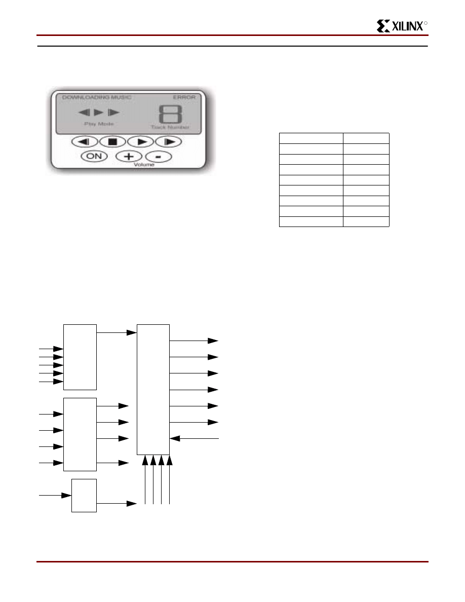
R
Design of a MP3 Portable Player using a CoolRunner CPLD
XAPP328 (v1.1) December 31, 1999
www.xilinx.com
27
1-800-255-7778
CoolRunner CPLD User Interface Control
A graphic of a proposed user interface for the CoolRunner
MP3 Portable Player is shown in
Figure 32: MP3 Portable Player User Interface
This interface controls the operations of the MP3 Player
and displays the current status. The User Interface Control
logic responds to user input on this interface and controls
the LCD display.
The user operations are divided into three categories,
Power Control, Sound Control and Play Modes. The Power
Control category is simply the On/Off operation. The Sound
Control functions include volume adjustments and the mute
function. Play Modes include Play, Stop, Rewind, and Fast
Forward. The User Interface Control Logic is therefore bro-
ken up into four main blocks, ON/OFF logic, Sound Control
Logic, Play Mode logic, and LCD Control Logic. The block
diagram is shown in
.
Figure 33: User Interface Control Logic Block
Diagram
Play Mode Logic
The Play Mode Logic block monitors the Play, Rew, Fwd,
and Stop buttons. When any button is pressed by a user, a
rising edge is detected on these signals. The play mode
chosen by the user is encoded on the PLAY_STAT[2:0] bus
as shown in
Table 6: Play Mode Encoding
The PLAY_STAT[2:0] bus is sent to the Main Control Logic
where the appropriate state machines and logic are
enabled to implement the chosen operation. The state
machine that controls the setting of the PLAY_STAT bus is
shown in
. Note that the status of the user inter-
face (stop or play) is maintained in the signal
CURR_MODE. In the case of a Rewind or Fast Forward
operation, this signal allows the user to return to the previ-
ous operation. For example, if the user was playing a song
and then hit REW, the MP3 portable player would resume
playing after the Rewind operation was complete. In some
cases, these signals indicate that the particular button
press can be ignored. For example, if the MP3 portable
player is currently in PLAY mode, additional presses of the
PLAY button are ignored. Also, if the MP3 Player is in IDLE
vol_inc
vol_dec
mute
play
stop
rew
fwd
pwr_switch
on_off
play_stat[2:0]
vol_lvl[5:0]
vol_adj
err
o
r
download
play_icon
fwd_icon
rwd_icon
track_icon
err_icon
downld_icon
Play
Modes
Sound
Control
On/Off
LCD
Display
Control
mute_stat
mute_chg
trac
k
[4:0]
flash_done
mpeg_done
s
ong_s
ta
rt
upd_track
PLAY_STAT[2:0]
Play Mode
000
Play
001
RWD
010
Stop
011
FWD
100
No-op
101
No-op
110
No-op
111
No-op
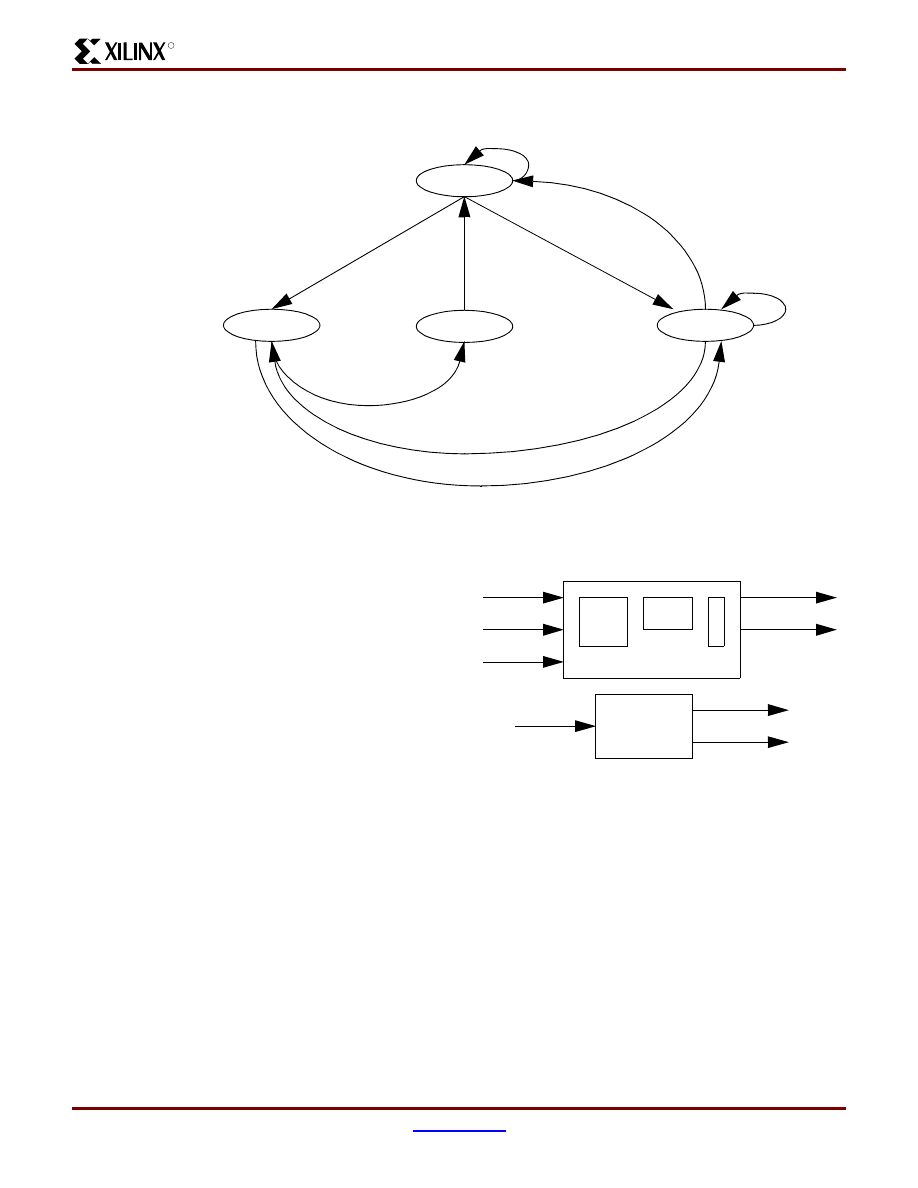
Design of a MP3 Portable Player using a CoolRunner CPLD
XAPP328 (v1.1) December 31, 1999
28
1-800-255-7778
R
mode, presses to the STOP button are ignored because
the MP3 Player is idle.
Figure 34: Play Mode Logic State Machine
Sound Control Logic
The Sound Control Logic block controls the user interface
for adjusting the volume and muting the output of the MP3
portable player. The block diagram for this logic is shown in
Volume adjustments are controlled at the DAC3550A by
writing a counter value to the AVOL register. Therefore
when the user increases or decreases the volume by
pressing the volume “+ “and “-” buttons, this counter is
incremented or decremented and the DAC3550A AVOL
register is updated with the new value. A change to the vol-
ume is indicated by the signal VOL_ADJ which triggers the
Main Control Logic State Machine to update the register in
the DAC3550A. The volume counter which represents the
desired volume level is output as VOL_LVL[5:0]. Note that
once the counter has reached either the maximum or mini-
mum level, additional presses to the “+” (maximum) or “-”
(minimum) have no further affect.
When the mute button is initially pressed, the sound is
muted. Additional presses of the mute button then toggle
the mute function on or off. The mute function is accom-
plished by writing zeros to the AVOL register of the
DAC3550A. When the mute function is disabled, the cur-
rent value of the volume counter is then written to the AVOL
register to restore the previous volume level. This is imple-
mented with a toggle flip-flop that toggles each time the
mute button is pressed. The value of the mute flip-flop
(MUTE_STAT) along with the indication that the mute func-
tion had changed (MUTE_CHG) are output to the Main
Control Logic so that the AVOL register of the DAC3550A is
updated.
Figure 35: Sound Control Logic
Volume Control State Machine
The state machine for controlling the volume of the MP3
Portable player is shown in
. If the VOL_INC or
VOL_DEC signal asserts, the state machine moves from
the IDLE state to the CHK_CNT state. In this state, the cur-
rent value of the counter is checked against the minimum
and maximum value. If the counter is at the minimum or
maximum value, the state machine returns to the IDLE
state and the VOL_ADJ signal is not asserted. If the
counter is not at one of the extremes, then the state
machine will increment and decrement the counter. The
state machine then moves to the INC_DEC state and
asserts the appropriate control line to the counter. The state
machine then moves to the ADJ state where it asserts the
VOL_ADJ line until the MPEG_DONE signal is asserted
ST_PLAY
ST_STOP
ST_RWD/FWD
ST_IDLE
rst=0
rwd=1,fwd=1
flash_done=0
play=1
curr_mode=1
flash_done=1
rwd=1,fwd=1
stop=1
flash_done=1
curr_mode=0
flash_done=1
VOL_CTRL
MUTE_CTRL
vol_inc
vol_dec
mute
vol_adj
vol_lvl[5:0]
mute_chg
mute_stat
Rising
Edge
Detect
State
Machine
Co
u
n
te
r
mpeg_done
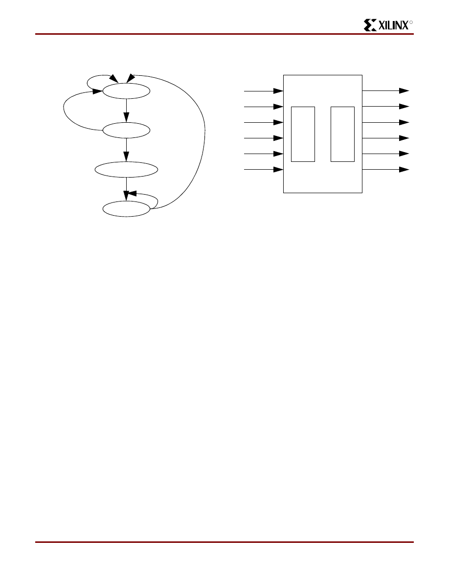
R
Design of a MP3 Portable Player using a CoolRunner CPLD
XAPP328 (v1.1) December 31, 1999
www.xilinx.com
29
1-800-255-7778
from the Main Control Logic indicating that the specified
register had been updated.
Figure 36: Volume Control State Machine
Mute Control Logic
The Mute Control Logic simply consists of a toggle flip-flop
that toggles with every rising edge of the MUTE signal. The
output of the rising edge detection circuit is MUTE_CHG
and MUTE_STAT is the output of the toggle flip-flop.
ON/OFF Logic
The ON/OFF logic maintains a signal with the on/off status.
The pressing of the ON button applies power to the DC/DC
convertor internal to the MAS3507D device and is not con-
trolled by this logic. An additional press of the ON button
turns the MP3 portable player OFF, but does not immedi-
ately remove power from the system. The DAC3550A
requires a power-down sequence, therefore the pressing of
the ON button to turn the system OFF sets the ON/OFF sig-
nal to ‘0’ indicating that the system needs to shutdown. This
signal is sent to the Power Management Logic which then
asserts the PWR_DWN signal to the Main Control Logic.
When the Main Control Logic has finished the power-down
sequence, it asserts the OFF_OK signal and the system
shuts down. The ON/OFF status is implemented with a T
flip-flop that toggles with a rising edge (button press) of the
ON button. This flip-flop is preset at power-up so that the
initial ON state is realized.
LCD Control Logic
The logic to control the LCD assumes that an LCD has
been designed with pre-defined icons as shown in
. This greatly simplifies the control of the LCD,
reducing it to simply turning icons on or off. The only part of
the display that requires more complex logic is driving the
7-segment displays to display the track number.
Figure 37: LCD Control Logic Block Diagram
Icon Control Logic
The Icon Control Logic simply consists of a 3:8 multiplexor
that decodes the PLAY_STAT bus and asserts the appro-
priate icon, registers to set the MUTE, ERROR, and
DOWNLOAD icon, and logic to decode the volume and bat-
tery levels to the appropriate icon value. If DISPLAY_ERR
is asserted, the ERROR icon is displayed with priority over
DNLD_MODE signal then takes priority and this icon is dis-
played. DISPLAY_ERR and DNLD_MODE must both be
negated for the other icons to be displayed.
IDLE
INC_DEC
ADJ
CHK_CNT
rst
inc=0
dec=0
inc=1
dec=1
cnt<>max
cnt<>min
mpeg_done=0
mpeg_done=1
cnt=max
cnt=min
play_icon
fwd_icon
rwd_icon
track_icon[6:0]
err_icon
downld_icon
IC
O
N
_CTR
L
7SEG
_C
T
R
L
display_err
dnld_mode
track[4:0]
play_stat[2:0]
song_start
upd_track
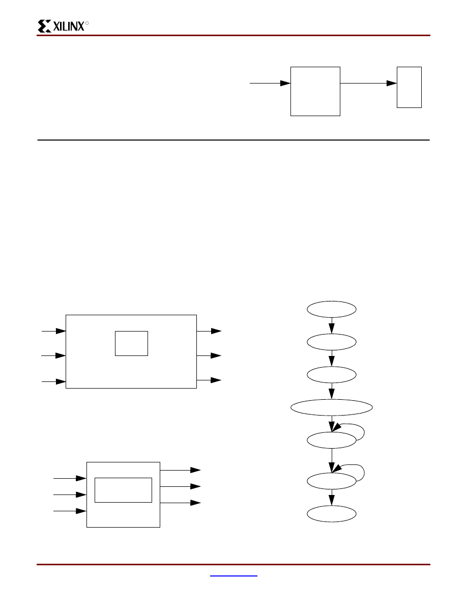
Design of a MP3 Portable Player using a CoolRunner CPLD
XAPP328 (v1.1) December 31, 1999
30
1-800-255-7778
R
7 Segment Control Logic
The 7 segment control logic contains the logic to display the
track number on the 7-segment display. This logic converts
the binary representation of the Track Number to the appro-
priate 7 segment display controls as shown in
Figure 38: 7 Segment Control Logic
CoolRunner CPLD Power Management Logic
Power management is crucial to the effective and reliable
operation of a portable MP3 player. Upon power-up, the
Power Management logic holds the rest of the system in
reset until the PUP line from the MAS3507D DC/DC con-
verter indicates that the power is stable. It continually mon-
itors the PUP line. If this signal indicates that the voltage is
below the minimum operating voltage or the User Interface
Logic indicates that the user has turned the device OFF, the
Power Management Logic asserts the PWR_DWN signal
to the Main Control Logic. This allows the Main Control
Logic to properly power-down the DAC3550A. When this is
complete, the Main Control Logic asserts the OFF_OK sig-
nal. The Power Management Logic then asserts FET_OFF
which controls the FET that removes power from the sys-
tem. The block diagram for this logic is shown in
Figure 39: Power Management Logic Block Diagram
Reset Control Logic
Figure 40: Reset Control Logic Block Diagram
Upon power-up, the Reset Control Logic (
) moni-
tors the PUP line from the MAS3507D. If the PUP line is
asserted indicating that the voltage is above the minimum
level, it negates the RESET signal to the rest of the Cool-
Runner CPLD logic after two wait states.
This logic continually monitors the PUP line from the
MAS3507D. If the MAS3507D PUP line negates, or the
user turns the MP3 portable player OFF, this logic begins
the power-down sequence by asserting the PWR_DWN
signal to the Main Control Logic. Once the Main Control
Logic has correctly power-downed the DAC3550A chip, it
asserts the OFF_OK signal and the reset control logic
asserts the FET_OFF signal to remove the battery power
from the DC/DC convertor of the MAS3507D.
Figure 41: Power Control State Machine
LCD
Binary to
7 Segment
Display
track[5:0]
track_icon[6:0]
pup
on_off
off_ok
pwr_dwn
rst
fet_off
Power Mgmt
Logic
Reset
Control
pup
on_off
off_ok
rst
fet_off
pwr_dwn
Power Control
State Machine
WAIT_PUP
NEGATE_PWRRST
NEGATE_RST
PWR_DWN
PWR_OFF
pup=0
on_off=0
off_ok=1
off_ok=0
WAIT_PUP_1
WAIT_PUP_2
pup=1
on_off=1
R
Design of a MP3 Portable Player using a CoolRunner CPLD
XAPP328 (v1.1) December 31, 1999
www.xilinx.com
31
1-800-255-7778
Conclusion
This document has detailed the logic design of the CoolRunner CPLD logic for a MP3 portable player. This design is
targeted for a 3.3V, 256 macrocell CoolRunner CPLD (XCR3256XL). This device has extremely low static and dynamic
power dissipation and therefore is ideally suited for this application. The design of the CoolRunner MP3 Portable Player has
also provided an example of using a CoolRunner CPLD in a portable application and can be extended to many other types
of portable applications as well.
Please note that the VHDL code described in this application note has been verified through simulation only. Therefore, this
VHDL code should be used only as an example. Designers downloading this VHDL design should modify and verify the
code for their end-application. Xilinx does not guarantee the accuracy or the functionality of this design.
Revision History
© 1999 Xilinx, Inc. All rights reserved. All Xilinx trademarks, registered trademarks, patents, and disclaimers are as listed at
http://www.xilinx.com/legal.htm
. All other trademarks and registered trademarks are the property of their respective
owners.
Date
Version Revision
11/15/99
1.0
Initial Xilinx release
12/30/99
1.1
Updated.
Document Outline
- Introduction
- MP3 Portable Player Block Diagram
- Operational Flows
- CoolRunner CPLD Main Control Logic
- CoolRunner CPLD Parallel Port Interface
- CoolRunner CPLD Flash Control Logic
- CoolRunner CPLD I2C Master Logic
- CoolRunner CPLD User Interface Control
- CoolRunner CPLD Power Management Logic
- Conclusion
- Revision History
Wyszukiwarka
Podobne podstrony:
Abolicja podatkowa id 50334 Nieznany (2)
4 LIDER MENEDZER id 37733 Nieznany (2)
katechezy MB id 233498 Nieznany
metro sciaga id 296943 Nieznany
perf id 354744 Nieznany
interbase id 92028 Nieznany
Mbaku id 289860 Nieznany
Probiotyki antybiotyki id 66316 Nieznany
miedziowanie cz 2 id 113259 Nieznany
LTC1729 id 273494 Nieznany
D11B7AOver0400 id 130434 Nieznany
analiza ryzyka bio id 61320 Nieznany
pedagogika ogolna id 353595 Nieznany
Misc3 id 302777 Nieznany
cw med 5 id 122239 Nieznany
D20031152Lj id 130579 Nieznany
mechanika 3 id 290735 Nieznany
więcej podobnych podstron