25
Small Tool Instruments and
Data Management
Pages 35–42
Pages 65–69
Pages 70–71
Pages 73–77
Pages 88–105
Pages 80–87
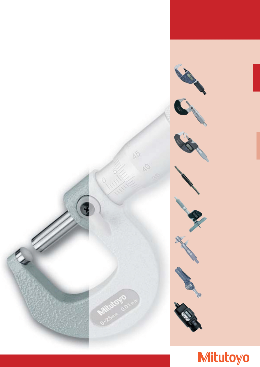
Analogue Micrometers
Digital Micrometers
Special Version Micrometers
External screw type micrometers
– accessories
Depth Micrometer
Inside Micrometers
Micrometer Heads
Threepoint Internal Micrometers
Pages 28–34
Pages 43–63
26
Measuring
Error limit
Tolerance of parallelism
range
G
of the measuring surfaces
at a measuring force of 10 N
mm
mm
mm
0 up to 25
4
2
25 up to 50
4
2
50 up to 75
5
3
75 up to 100
5
3
100 up to 125
6
3
125 up to 150
6
3
150 up to 175
7
4
175 up to 200
7
4
200 up to 225
8
4
225 up to 250
8
4
250 up to 275
9
5
275 up to 300
9
5
300 up to 325
10
5
325 up to 350
10
5
350 up to 375
11
6
375 up to 400
11
6
400 up to 425
12
6
425 up to 450
12
6
450 up to 475
13
7
475 up to 500
13
7
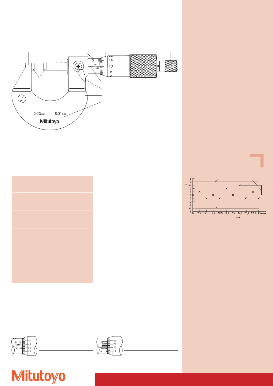
Basic Information on Micrometers
Accuracy of micrometers according to DIN 863 (as of 1999)
Measuring anvil
Carbide
measuring
surfaces
Measuring spindle
Error limit
Error limit
Gauge block length
Deviation
Diagram of the deviations of a micrometer with measuring range
0 mm to 25 mm which has been set to the initial value of the
measuring range.
Max. deviation
sleeve
Thimble
Ratsche
Limit of error G (DIN 863)
Limit of error G must be complied with on setting
the indication at any point in the measuring range
(see diagram)
For the design with vernier: 0,001 mm
Reading from the sleeve:
6,00 mm
Reading from the thimble: 0,21 mm
Reading from the vernier: 0,003 mm
Total reading
6,213 mm
Reference line
Spindle setting element
Frame
Insulation
Tolerance of flatness of the surfaces: 0,6 mm
Mitutoyo outside micrometers are available
up to a range of 2000 mm.
How to read the micrometer correctly:
For the design with division: 0,01 mm
Reading from the sleeve:
7,00 mm
Reading from the thimble: 0,37 mm
Total reading
7,37 mm
Testing the error limit G
The compliance with error limit G can be tested
using gauge blocks of tolerance class 1 according to
DIN ISO 3650.
The gauge blocks have to be combined in such a
way that the measuring spindles can be tested in
a way that corresponds to an integral multiple of
the nominal pitch as well as at all places situated in
between.
The following gauge block combinations are
recommended: 2,5; 5,1; 7,7; 10,3; 12,9; 15,0; 17,6;
20,2; 22,8; 25 mm
Gauge blocks from page 303
27
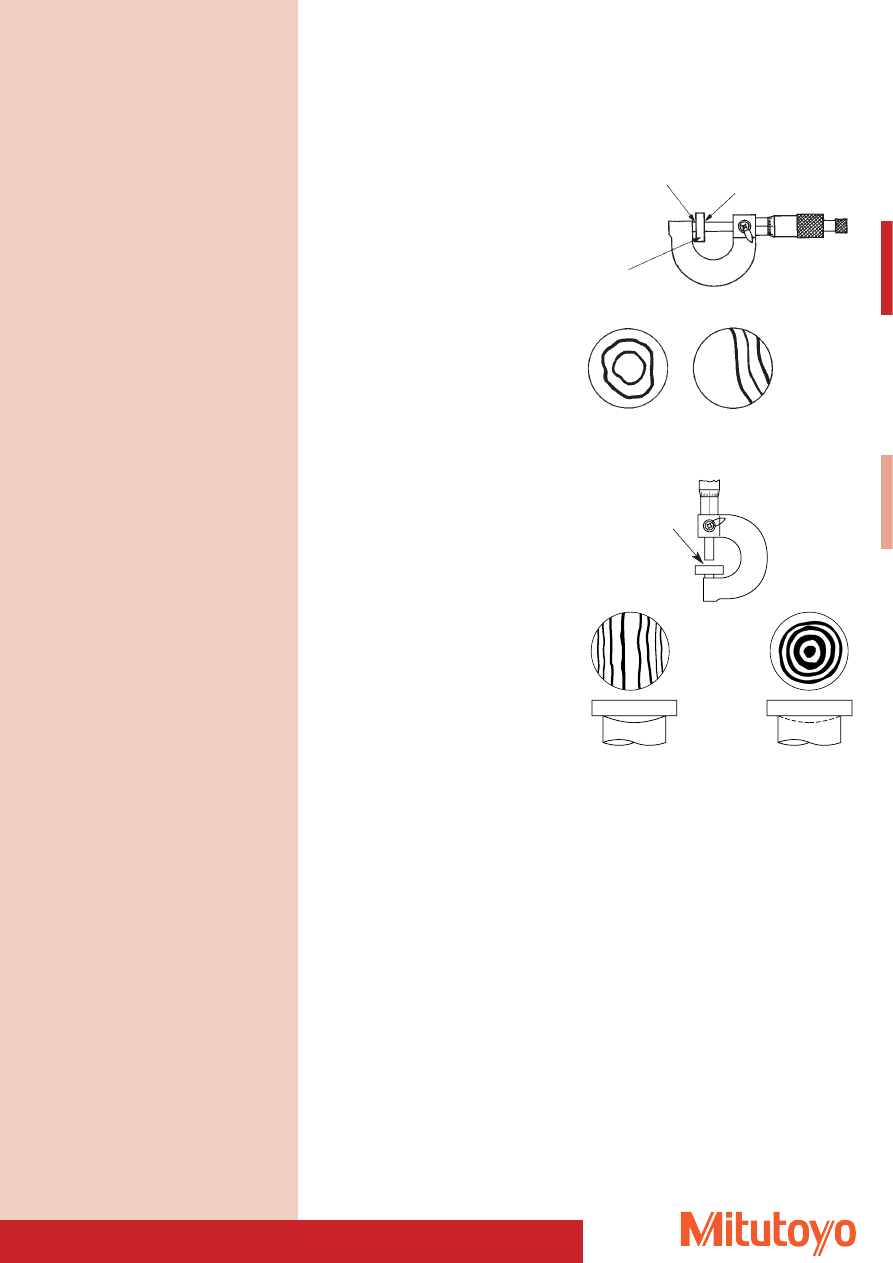
Testing Parallelism and Flatness
These tests are performed with optical glass flats which are pressed onto the surfaces to be tested.
As a result of narrow air wedges between the glass plate and the measuring surface, interference bands
occur whose centers are 0.32 mm apart (with an assumed light wavelength of 640 nm).
Parallelism of measuring surfaces
The parallelism of the measuring surfaces of outside
micrometers with measuring ranges of 0 to 25 mm,
25 to 50 mm, 50 to 75 mm and 75 to 100 mm can be
tested using three or four plane-parallel test glasses
whose length differs from the spindle pitch by around
one third or one quarter, so that the test can be
performed at three or four points on a full revolution
of the spindle. The plane-parallel test-glass is placed
against the measuring surface using the coupling.
By carefully moving the test glass between the
measuring surfaces, the smallest number of visible
interference rings or bands on a measuring surface is
determined, and the number of interference rings or
bands on the opposite measuring surface is added to
this. A fringe zone of a maximum of 0.4 mm is not
taken into account during the test.
Flatness of measuring surfaces
The flatness of measuring surfaces is tested with a flat
that minimises the number of interference bands or
rings and forms close curves.
A fringe zone of a maximum of 0.4 mm is not taken
into account during the test.
Viewing direction spindle
Viewing direction anvil
Planparallel testglass
Concave or spherical
measuring surface
Parallelism
3 x 0,32 mm W approx. 1 mm
Measuring anvil
Measuring spindle
Viewing direction
Curved
measuring surface
Concave
measuring surface
Glass flat
Glass flat
Measuring anvil
Measuring anvil
See page 67 for optical glass flats
and optical parallels
28
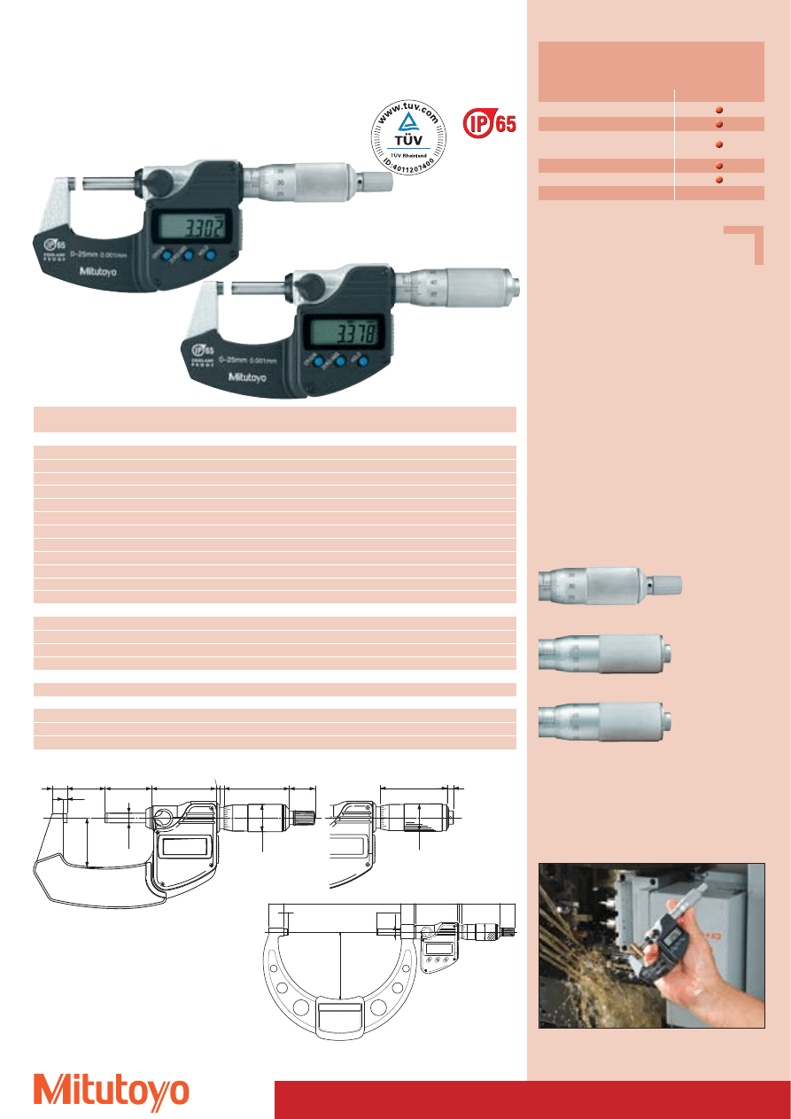
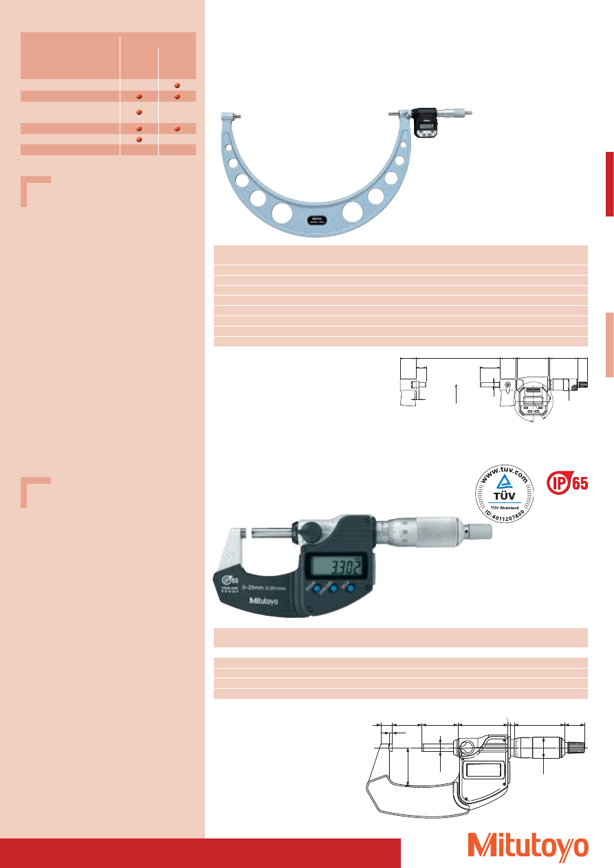
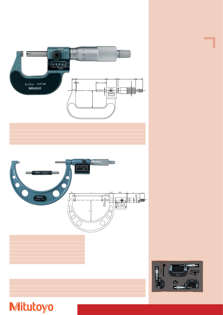
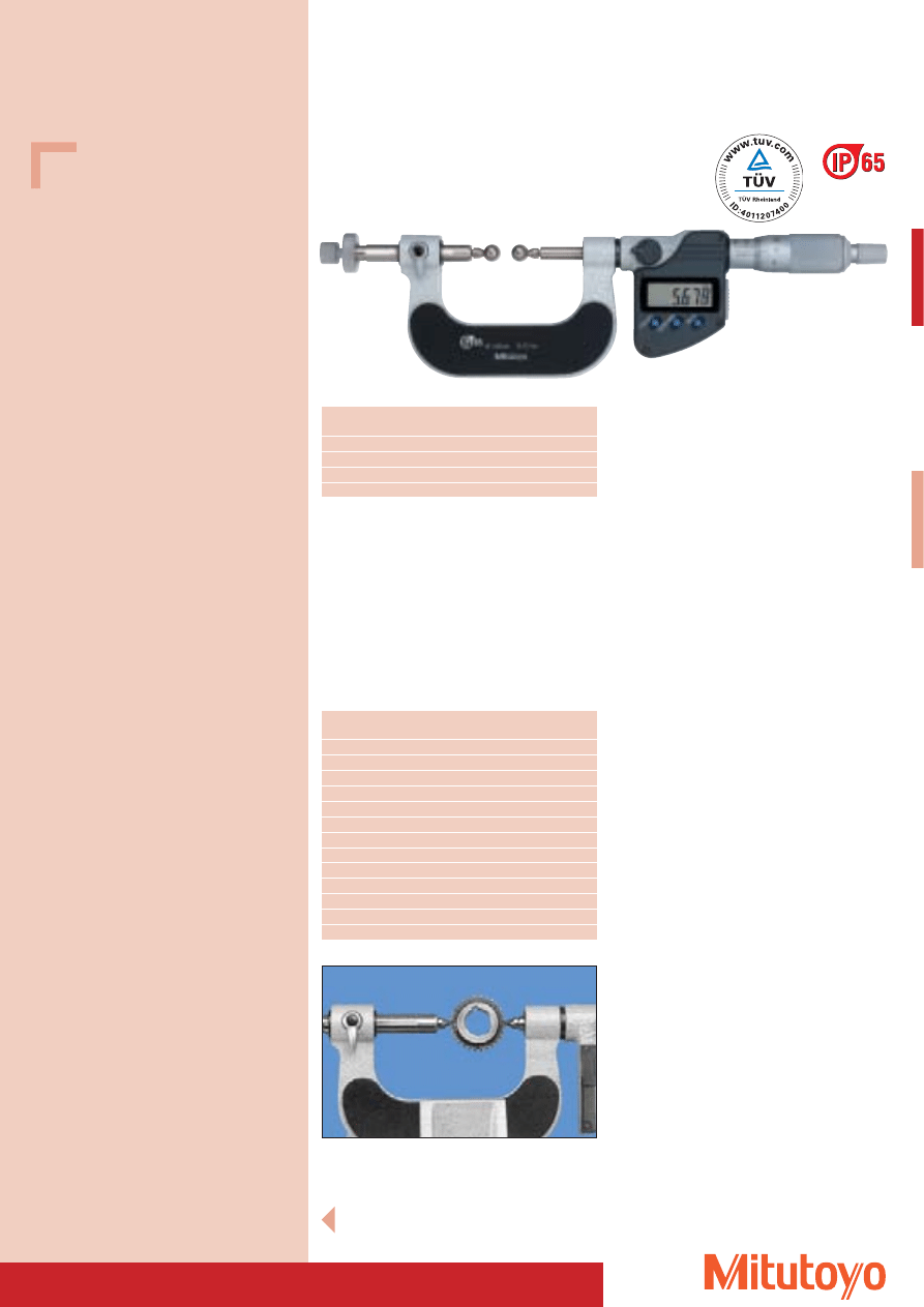
“DIGIMATIC” Micrometer
• Digital standard external screw type micrometer with IP-65 protection.
Series 293
with data output
Specifications
Accuracy:
Factory specification
Resolution:
0,001 mm
Scales:
thimble and sleeve
satin chrome finish
Measuring surfaces: carbide-tipped,
precision ground,
micro-lap finish
Frame:
enamelled
Measuring force:
5–10 N
Including box, key, 1 battery,
gauge block from 25 mm and up to 50 mm
measuring range with factory certificate
Optional accessories
No. 05CZA662
Signal cable with data key (1 m)
No. 05CZA663
Signal cable with data key (2 m)
Consumable Spares
No. 938882
Battery SR-44
44
4.2
ø18
17
43
2.3
3
a
30.7
b
42.5
c
ø6.35
ø18
L
5
0
45
14.5
L
27.5
a
C
b
17
43
3
Ø 18
47.2
2
2.3
Ø 6,35
With ratchet (standard version)
Ratchet thimble
Friction thimble
Measuring range up to 0–100 mm
Measuring range up to 100–300 mm
293–238
with friction thimble
293–230
with ratchet (standard version)
* Accuracy exceeding the requirements of DIN 863
Functions
Series 293
ORIGIN up to 100 mm
ZERO/ABS
Preset from 100 mm upwards
(replacing ORIGIN function)
HOLD
Data output
Measuring range
No.
Error limit*
L
a
b
c
Mass
mm
mm
mm
mm
mm
mm
g
With ratchet (standard version)
0– 25
293–230
2
–
2,8
9,0
25,0
270
25– 50
293–231
2
25,0
2,8
9,8
32,0
330
50– 75
293–232
2
50,0
2,8
12,6
47,0
470
75–100
293–233
3
75,0
2,8
14,0
60,0
625
100–125
293–250
3
132,8
5,3
16,7
76,5
600
125–150
293–251
3
158,2
5,7
18,8
91,0
740
150–175
293–252
4
183,6
6,1
19,1
103,1
800
175–200
293–253
4
208,8
6,3
18,2
115,3
970
200–225
293–254
4
234,2
6,7
16,8
126,8
1100
225–250
293–255
5
258,0
5,5
18,0
139,8
1270
250–275
293–256
5
284,0
6,5
18,0
152,3
1340
275–300
293–257
5 309,0
6,5
18,0
166,0
1540
With ratchet thimble
0– 25
293–234
2
–
2,8
9,0
25,0
270
25– 50
293–235
2
25,0
2,8
9,8
32,0
330
50– 75
293–236
2
50,0
2,8
12,6
47,0
470
75–100
293–237
3
75,0
2,8
14,0
60,0
625
With friction thimble
0– 25
293–238
2
–
2,8
9,0
25,0
270
Set
Contents:
0– 50
293–966
293–230, 293–231
0– 75
293–962
293–230, 293–231, 293–232
0–100
293–963
293–230, 293–231, 293–232, 293–233
The use of top quality materials provides outstanding
resistance to oils and chemicals
29
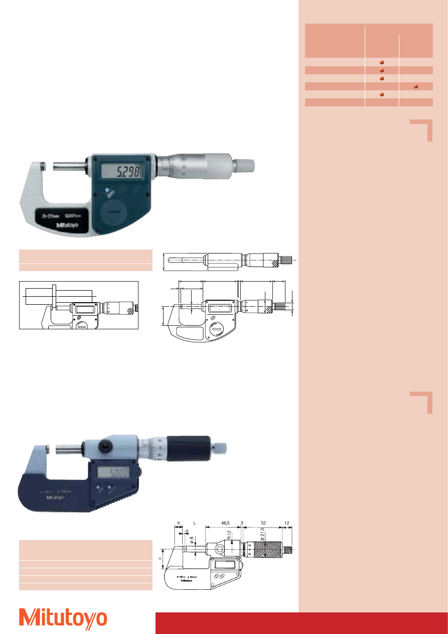
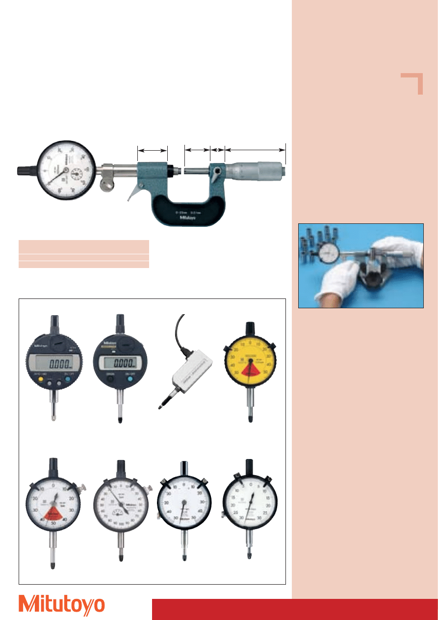
“DIGIMATIC” Micrometer
• Digital standard micrometer with IP-65 protection, large digits and 1 mm resolution.
Series 293
without data output
Specifications
Accuracy:
Factory specification
Resolution:
0,001 mm
Scales:
thimble and sleeve
satin chrome finish
Measuring surfaces: carbide-tipped,
precision ground,
micro-lap finish
Frame:
enamelled
Measuring force:
5–10 N
Including box, key, 1 battery,
gauge block from 25 mm and up to 50 mm
measuring range with factory certificate
Consumable Spares
No. 938882
Battery SR-44
Measuring range
No.
Error limit*
L
a
b
c
Mass
mm
mm
mm
mm
mm
mm
g
With ratchet (standard version)
0– 25
293–240
2
–
9,0
25
59,8
270
25– 50
293–241
2
25
9,8
32
70,3
330
50– 75
293–242
2
50
12,6
47
91,9
470
75–100
293–243
3
75
14,0
60
112,9
625
Measuring range
No.
L
a
b
c
Mass
mm
mm
mm
mm
mm
g
300–325
293–571
353
18
28
187
2085
325–350
293–572
378
18
28
199
2255
350–375
293–573
403
18
28
212
2405
375–400
293–574
428
18
28
224
2555
400–425
293–575
453
18
28
236
2815
425–450
293–576
478
18
28
248
3065
450–475
293–577
503
18
28
261
3315
475–500
293–578
528
18
28
273
3550
“DIGIMATIC” Micrometer
• Digital standard micrometer, measuring range 300–500 mm.
Specifications
Accuracy:
according to DIN 863-1
Resolution:
0,001 mm
Scales:
thimble and sleeve
satin chrome finish
Measuring spindle: with spindle lock
Measuring surfaces: carbide-tipped,
precision ground,
micro-lap finish
Frame:
enamelled
Measuring force:
10–14 N
Including box, gauge block, key,
2 batteries
Optional accessories
No. 937387
Signal cable (1 m)
No. 965013
Signal cable (2 m)
Consumable Spares
No. 938882
Battery SR-44
c
35
28 2
55
330
3
50
17
L
5
Ø 8
Ø 2
1
a
b
Ø 12
293–240
293–572
Series 293
293–571
293–240
up to
up to
Functions
293–578
293–243
ORIGIN
ZERO/ABS
Preset from 100 mm upwards
(replacing ORIGIN function)
HOLD
Data output
Series 293
DIN 863-1 with data output
17
43
2.3
3
a
30.7
b
42.5
c
ø6.35
ø18
L
* Accuracy exceeding the requirements of DIN 863
30
Specifications
Accuracy:
according to DIN 863-1
Resolution:
0,001 mm
Scales:
thimble and sleeve
satin chrome finish,
Ø 18 mm
Measuring surfaces: carbide-tipped,
precision ground,
micro-lap finish
Including box, key, 1 battery
Consumable Spares
No. 938882
Battery SR-44
293–805
22
Ø
6.35
44.5
1.5 3
43
17
Ø1
8
31.5
Ø9.7
29
2.5
25
Series 293
DIN 863-1 without data output
“DIGIMATIC” Micrometer
• Handy and slim design compared to customary available micrometers.
Measuring range
No.
Measuring force
Mass
mm
N
g
0–25
293–805
5–10
250
“DIGIMATIC” Micrometer
• External screw type micrometer with 1 mm pitch to avoid reading errors.
• With large measuring surfaces.
Series 293
DIN 863-1 with data output
293–151–30
Measuring
No.
L
a
b
c
Mass
range
mm
mm
mm
mm
mm
g
0– 25
293–151–30
31,8
2,8
7
26
320
25– 50
293–152–30
56,8
2,8
7
33
390
50– 75
293–153–30
81,8
2,8
10
48
530
75–100
293–154–30 106,8
2,8
11
61
670
Specifications
with ratchet thimble
Accuracy:
according to DIN 863-1
Resolution:
0,001 mm
Scales:
thimble and sleeve
satin chrome finish,
Ø 21,5 mm
Measuring spindle: with spindle lock
Measuring surfaces: carbide-tipped,
precision ground,
micro-lap finish
Frame:
enamelled
Measuring force:
5–10 N
Steigung:
1 mm
Including box, gauge block (from 25–50 mm),
insulation, key, 1 battery
Optional accessories
No. 937387
Signal cable (1 m)
No. 965013
Signal cable (2 m)
Consumable Spares
No. 938882
Battery SR-44
Series 293
293–151–30
up to
Functions
293–154–30
293–805
ORIGIN
ZERO /ABS
DATA / HOLD
ZERO
Data output
31
Series 293
293–666
up to
Functions
293–669 293–661–10
ON / OFF
ORIGIN
DATA / HOLD
ZERO /ABS
(from 25–50 mm)
Data output
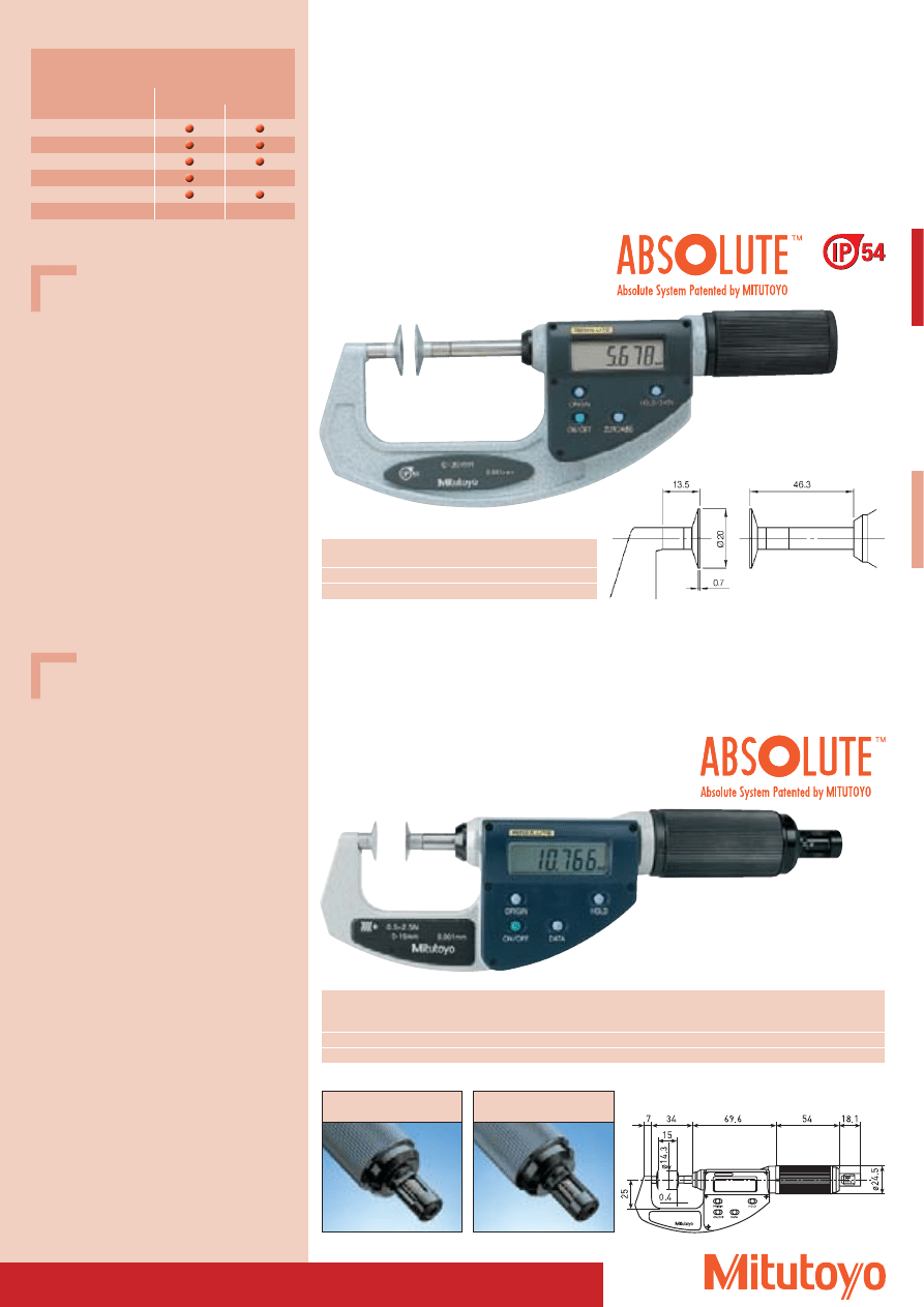
A
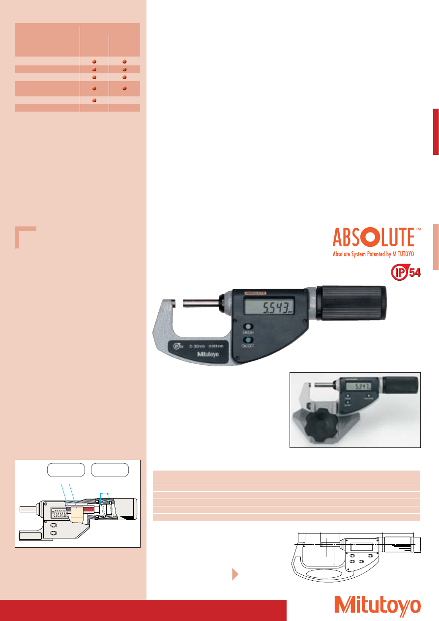
“DIGIMATIC” Quick Micrometer
• Large digits, long battery life
Easy to read display due to large digits with 7,5 mm in height. Exceptional battery life of 3,5 years
lasting three times as long as customary batteries with micrometers.
• Precision measurement at high speeds
These micrometers feature an absolute linear scale with a resolution of 1 mm.
Due to the
A scale display errors with high speed movement are being prevented.
There are no restrictions with regards to the movement speed.
• IP–54 protection
Manufactured according to IP–54 protection standards.
(IP–54 protection does not apply when the protective cover is open or a signal cable connected
to the data output.) Also for series 369 and 422 (see pages 33 and 34).
• Precise measuring on delicate, soft surfaces
Since the micrometer is equipped with non-rotating spindle even delicate surfaces can be measured.
Series 293
“Quick” external screw type micrometer
in standard version
With non-rotating spindle
Measuring range
No.
Error limit
Flatness
Parallelism
Measuring force
a
b
x
Mass
mm
mm
mm
mm
N
mm
mm
mm
g
0– 30
293–661–10*
2
울 0,3
울 2,0
5–10
9,0
25
–
275
0– 30
293–666
2
울 0,3
울 2,0
5–10
9,0
25
–
275
25– 55
293–667
3
울 0,3
울 2,0
5–10
11,3
36
25
355
50– 80
293–668
3
울 0,3
울 2,0
5–10
13,1
47
50
525
75–105
293–669
3
울 0,3
울 2,0
5–10
13,5
60
75
625
b
Ø24.9
50.4
69.6
32
a
Ø6.35
x
x = smallest measuring range
Special versions can be found
on the next pages
* without data output
293–666 with fixing device 156–105 M
(optional accessories)
Specifications
Accuracy:
Factory specification
Resolution: 0,001 mm
Frame:
enamelled
Including box, gauge block (from 25–55 mm),
1 battery
Optional accessories
No. 937387
Signal cable (1 m)
No. 965013
Signal cable (2 m)
Consumable Spares
No. 938882
Battery SR-44
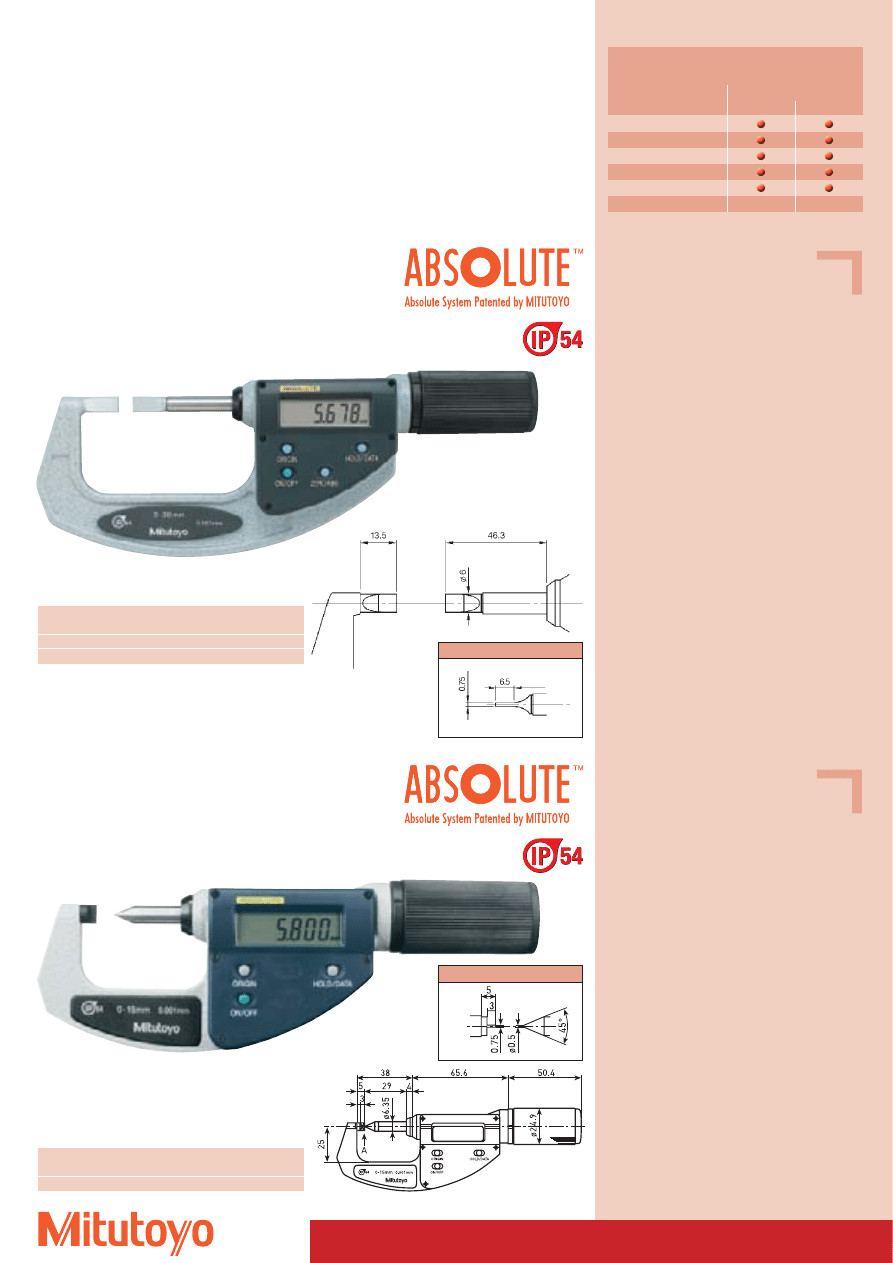
ORIGIN
10 mm
Scale Detector
Spindle pitch
10 mm/U
This micrometer has a newly developed spindle
mechanism enabling a spindle drive of 10 mm/U
and a measuring range of 30 mm.
The drive rate is therefore 20 x higher than in
conventional micrometers.
293–661–10
TM
Patent numbers see page 464
A scale
with origin point
Rapid adjustment
32
227–201
227–203
Functions
227–202
227–204
ON / OFF
ORIGIN
DATA / HOLD
ZERO /ABS
Data output
A
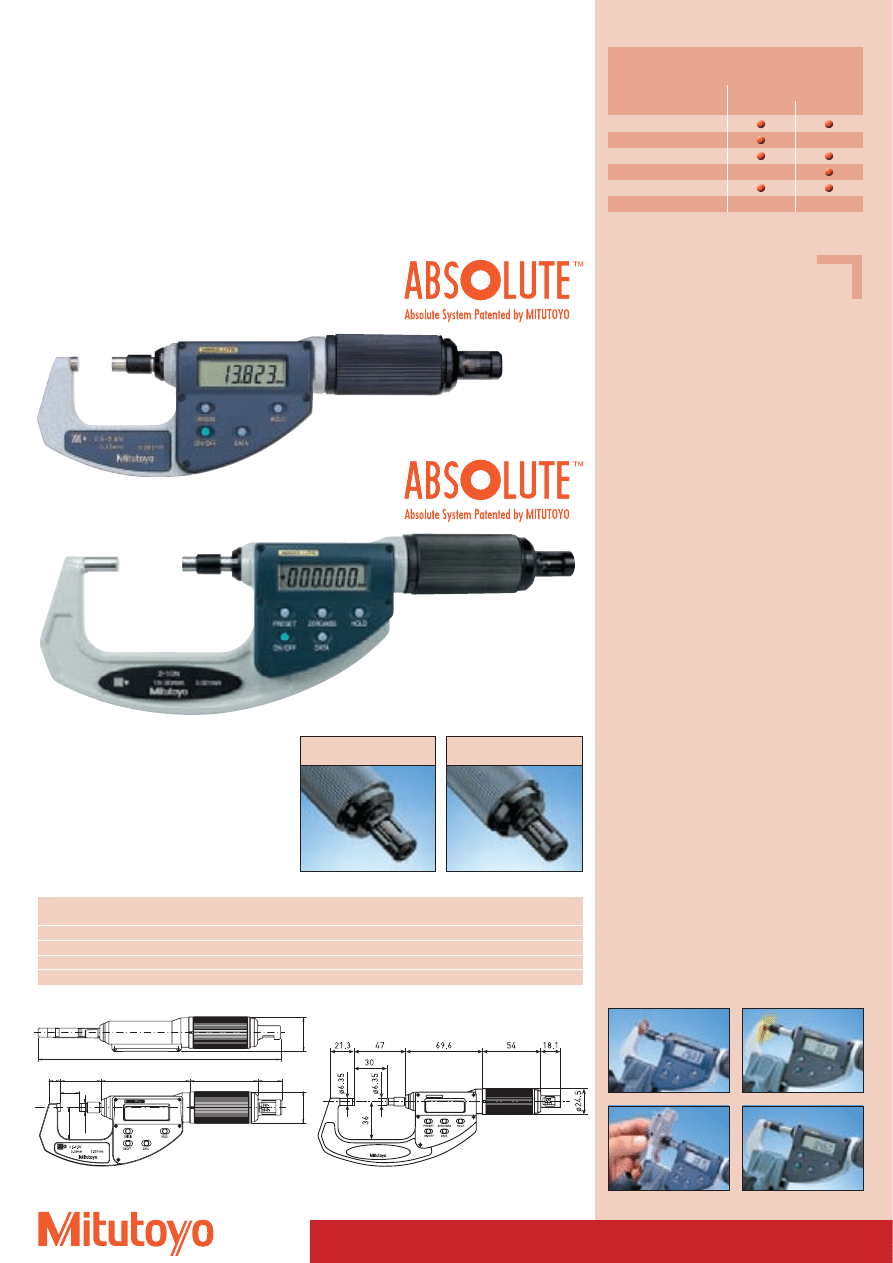
“DIGIMATIC” Quick Micrometer
• For principle of function and advantages, see page 31.
Series 227
“Quick” external screw type micrometer with adjustable measuring force
Measuring force: 0,5– 2,5 N
(at 227–201 / 227–203)
,
2,0–10,0 N
(at 227–202 / 227–204)
0-15
Ø 24.5
Ø 26
9
32
69.6
53.4
17.7
Ø 6.35
25
190.2
No.
Measuring range Adjustable range
Measuring force (N)*
Error limit der Measuring force
Error limit
Mass
mm
of measuring force
Scala
(pre-set measuring force)
mm
g
227–201
0–15
0,5– 2,5 N
0,5; 1,0; 1,5; 2,0; 2,5
0,1 + (adjusted measuring force / 10) N
2
300
227–202
0–15
2,0–10,0 N
2; 4; 6; 8; 10
0,4 + (adjusted measuring force / 10) N
2
300
227–203
15–30
0,5– 2,5 N
0,5; 1,0; 1,5; 2,0; 2,5
0,1 + (adjusted measuring force / 10) N
2
380
227–204
15–30
2,0–10,0 N
2; 4; 6; 8; 10
0,4 + (adjusted measuring force / 10) N
2
380
* This model is also available as special manufacture with fixed measuring force.
Specifications
Accuracy:
Factory specification
Resolution:
0,001 mm
Flatness:
울 0,3 mm
Parallelism:
울 2 mm
Frame:
enamelled
Measuring direction: horizontal *
Including box, gauge block (from 15–30 mm),
screwdriver, 1 battery
* = Modification of the measuring direction affects
the measuring force due to the gravitational
force;
the deviations guaranteed are only valid for
horizontal measuring direction (± 3 degrees).
Optional accessories
No. 937387
Signal cable (1 m)
No. 965013
Signal cable (2 m)
Consumable Spares
No. 938882
Battery SR-44
227–201 / –202
227–203 / –204
227–201
227–204
Measuring force adjustable:
2–10 N
Measuring force adjustable:
0,5–2,5 N
TM
Patent numbers see page 464
33
Specifications
Accuracy:
Factory specification
Resolution:
0,001 mm
Measuring force:
3–8 N
Frame:
enamelled
Including box, gauge block (from 25–55 mm),
1 battery
Optional accessories
No. 937387
Signal cable (1 m)
No. 965013
Signal cable (2 m)
Consumable Spares
No. 938882
Battery SR-44
A
“DIGIMATIC” Quick Micrometer
• For principle of function and advantages, see page 31.
Series 369
”Quick“ Micrometer with non-rotating spindle and disc-shaped measuring surfaces
for measuring felt, rubber, cardboard, fabric etc.
Measuring range
No.
Error limit Measuring surface Mass
mm
mm
Offset mm
g
0–30
369–411
4
Ø 20
360
25–55
369–412
4
Ø 20
490
369–411
Functions
Series 369
Series 227
ON / OFF
ORIGIN
DATA / HOLD
ZERO /ABS*
Data output
* Only measuring range 25–55 mm
Specifications
Accuracy:
Factory specification
Resolution:
0,001 mm
Flatness:
울 1 mm
Parallelism:
울 3 mm
Frame:
enamelled
Measuring direction: horizontal *
Including box, screwdriver, 1 battery
* = Modification of the measuring direction affects
the measuring force due to the gravitational
force;
the deviations guaranteed are only valid for
horizontal measuring direction (± 3 degrees).
Optional accessories
No. 937387
Signal cable (1 m)
No. 965013
Signal cable (2 m)
Consumable Spares
No. 938882
Battery SR-44
Series 227
”Quick“ Micrometer with non-rotating spindle and disc-shaped measuring surfaces
and adjustable measuring force for measuring felt, rubber, cardboard etc.
Measuring force: 0,5 – 2,5 N
(at 227–221)
2,0 – 10,0 N
(at 227–222)
227–221
No.
Measuring Adjustable range Measuring force (N)*
Error limit of measuring force
Error Measuring range Mass
range
of measuring force
Scala
(pre-set measuring force)
limits
Continuous
mm
mm
Ø mm
g
227–221
0–15
0,5– 2,5 N
0,5; 1,0; 1,5; 2,0; 2,5 0,1 + (adjusted measuring force / 10) N
4
14,3
300
227–222
0–15
2,0–10,0 N
2; 4; 6; 8; 10
0,4 + (adjusted measuring force / 10) N
4
14,3
300
* This model is also available as special manufacture with fixed measuring force.
227–221 / 227–222
Measuring force adjustable:
2–10 N
Measuring force adjustable:
0,5–2,5 N
TM
Patent numbers see page 464
34
A
“DIGIMATIC” Quick Micrometer
• For principle of function and advantages, see page 31.
Series 422
”Quick“ Micrometer with non-rotating spindle
and offset measuring surfaces
for measuring narrow outside grooves
Specifications
Accuracy: Factory specification
Resolution: 0,001 mm
Frame:
enamelled
Including box, gauge block (from 25–55 mm),
1 battery
Optional accessories
No. 937387
Signal cable (1 m)
No. 965013
Signal cable (2 m)
Consumable Spares
No. 938882
Battery SR-44
Series 342
”Quick“ Micrometer with non-rotating spindle
for measuring crimp heigths
Measuring range
No.
Error limit
Measuring force Mass
mm
mm
N
g
0–15
342–451
3
4–6
275
Specifications
Accuracy: Factory specification
Resolution: 0,001 mm
Frame:
enamelled
Including box, 1 battery
Optional accessories
No. 937387
Signal cable (1 m)
No. 965013
Signal cable (2 m)
Consumable Spares
No. 938882
Battery SR-44
Functions
Series 422
Series 342
ON / OFF
ORIGIN
DATA / HOLD
ZERO /ABS*
Data output
* Only measuring range 25–55 mm
342–451
Measuring surfaces
Measuring range
No.
Error limit
Measuring force Mass
mm
mm
N
g
0–30
422–411
3
5–10
350
25–55
422–412
3
5–10
490
422–411
TM
Patent numbers see page 464
Measuring surfaces
35
Outside Micrometer
Series 101
DIN 863-1 Small version
101–101
Measuring range
No.
Mass
mm
g
0–15
101–101
125
Series 102
DIN 863-1 Rugged design
Measuring
No.
Graduation
L
a
b
c
d
Mass
range
mm
mm
mm
mm
mm
mm
mm
g
0– 25
102–301
0,01
30,3
2,8
5
26
6,35
180
25– 50
102–302
0,01
55,3
2,8
8
32
6,35
270
50– 75
102–303
0,01
80,3
2,8
9
45
6,35
375
75–100
102–304
0,01
105,3
2,8
10
58
6,35
490
0– 25
102–307
0,001
30,3
2,8
5
26
6,35
180
25– 50
102–308
0,001
55,3
2,8
8
32
6,35
270
with friction thimble
0– 25
102–305
0,01
30,3
2,8
5
26
6,35
180
25– 50
102–306
0,01
55,3
2,8
8
32
6,35
270
Series 102
As a set
Measuring range
No.
Set combination
Mass
mm
g
0–100
102–911
102–301/302/303/304
1315
Specifications
Accuracy:
DIN 863-1
Graduation:
0,01 mm
Scales:
thimble and sleeve
satin chrome finish,
Ø 15 mm
Measuring spindle: Ø 6,35 mm
spindle pitch 0,5 mm
with spindle lock
Measuring surfaces: carbide-tipped,
precision ground and
micro-lap finish
Frame:
forged steel frame,
satin chrome finish
Measuring force:
5–10 N
Including box, key
Specifications
Accuracy:
DIN 863-1
Scales:
thimble and sleeve
satin chrome finish,
Ø 18 mm
Measuring spindle: spindle pitch 0,5 mm
with spindle lock
Measuring surfaces: carbide-tipped,
precision ground and
micro-lap finish
Frame:
enamelled
Measuring force:
5–10 N
Including box, gauge block (from 25–100 mm),
up to 50 mm with factory certificate, insulation,
key
102–305 friction thimble
Ø 15
Ø 6.35
19.5
3
14.5
20
2.5
17.5
17
37
b
a
L
14.5
3
47
17
Ø 18
Ø d
c
27.5
102–911
102–301
36
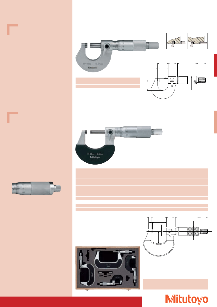
Micrometers with ratchet thimble
• Quick micrometer with combined ratchet stop.
• For single-handed operation and operation in the holder.
• High level of safety when used in single-handed operation. Test results show that unaccustomed users
obtain significantly better results with the new Quick micrometer.
• With factory certificate.
Series 102
Measuring
No.
Graduation
L
a
b
c
d
Mass
range
mm
mm
mm
mm
mm
mm
mm
g
0– 25
102–701
0,01
30,3
2,8
5
26
6,35
180
0– 25
102–707
0,001*
55,3
2,8
8
32
6,35
270
Specifications
Accuracy:
Factory specification
Error limit:
3 mm
Scales:
thimble and sleeve
satin chrome finish,
Ø 18 mm
Measuring spindle: spindle pitch 0,5 mm
with spindle lock
Measuring surfaces: carbide-tipped,
precision ground and
micro-lap finish
Frame:
enamelled
Flatness of
measuring surfaces: 0,6 mm
Parallelism of
measuring surfaces: 2 mm
Measuring force:
5–10 N
Including box, with factory certificate, insulation,
key
b
a
L
14.5
3
47
17
Ø 18
Ø d
c
27.5
Single-handed operation
The rapid adjuster can be used to turn the spindle
quickly at any time
102–701
Thimble
(ratchet)
Rapid adjustment
(ratchet)
Including box and with factory certificate
* Nonius
37
Specifications
Accuracy:
DIN 863-1
Graduation:
0,01 mm
Scales:
thimble and sleeve
satin chrome finish,
Ø 21 mm
Measuring spindle: Ø 8 mm
spindle pitch 1 mm
with spindle lock
Measuring surfaces: carbide-tipped,
precision ground and
micro-lap finish
Frame:
forged, satin chrome finish
Measuring force:
5–10 N
Including box, gauge block (25–50 mm),
insulation, key
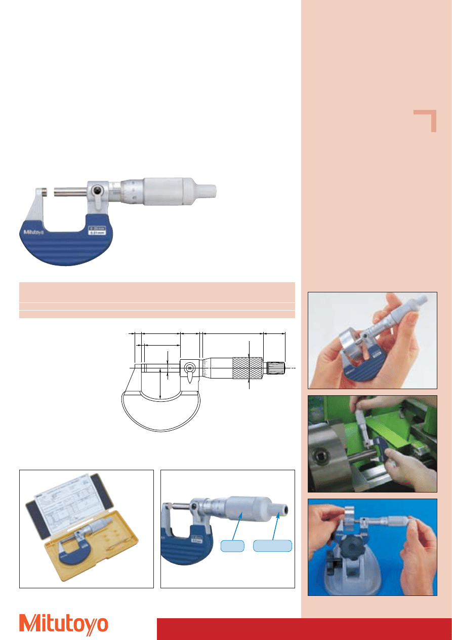
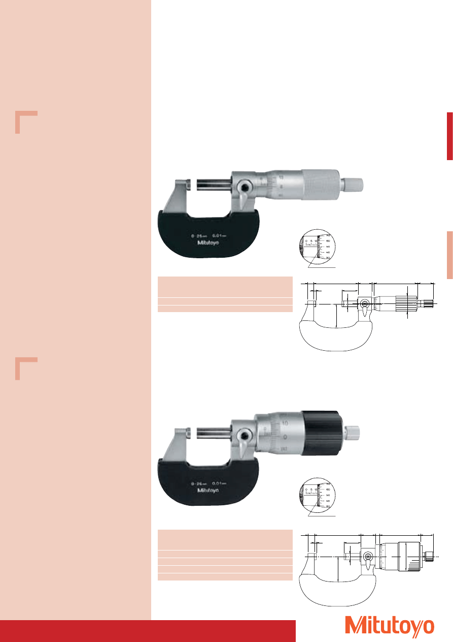
Outside Micrometer
Series 102
DIN 863-1
Heavy duty workshop design
With 1 mm spindle pitch to avoid display error
Measuring
No.
L
a
b
c
Mass
range
mm
mm
mm
mm
mm
g
0–25
102–450
30
2,5
5
26,0
270
25–50
102–451
55
2,5
8
32,5
310
with 100 step graduation
(pitch 1 mm)
The measured values can be read directly from
the 100 step graduation on the thimble without
calculation of mm-values.
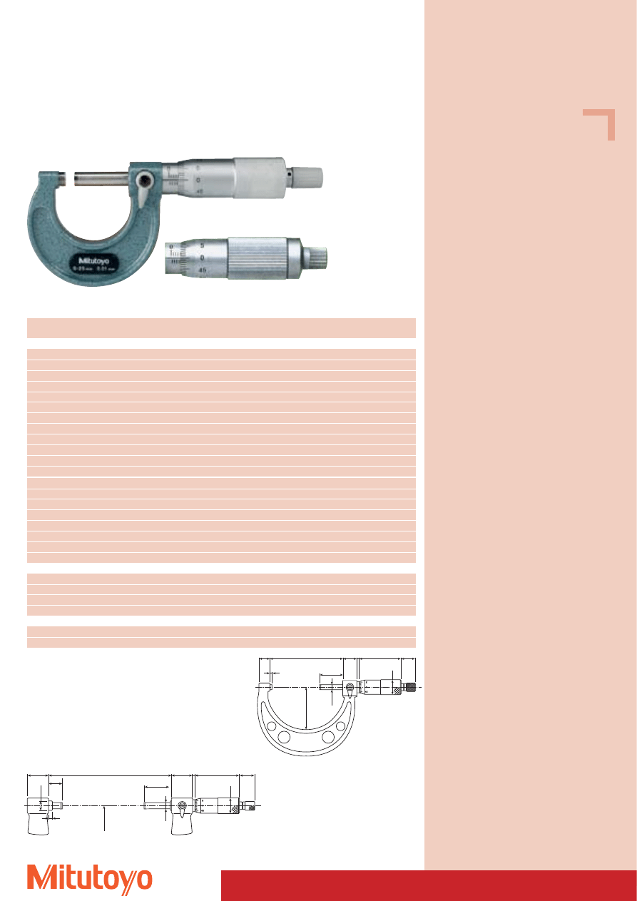
Series 102
DIN 863-1
Large Thimble
With 1 mm spindle pitch to avoid display error
102–650
Measuring
No.
L
a
b
c
Mass
range
mm
mm
mm
mm
mm
g
0– 25
102–650
30
2,5
5
26,0
345
25– 50
102–651
55
2,5
8
32,5
405
50– 75
102–652
80
2,5
9
45,0
570
75–100
102–653
105
2,5
9
58,0
640
16
L
27.5
b
c
Ø8
a
3
50
17
Ø21
0
10
90
13
49.5
5
16
L
27.5
b
c
Ø30.7
Ø8
a
with 100 step graduation
(pitch 1 mm)
The measured values can be read directly from
the 100 step graduation on the thimble without
calculation of mm-values.
102–450
Specifications
Accuracy:
DIN 863-1
Graduation:
0,01 mm
Scales:
thimble and sleeve
satin chrome finish,
Ø 30 mm
Measuring spindle: Ø 8 mm
spindle pitch 1 mm
with spindle lock
Measuring surfaces: carbide-tipped,
precision ground and
micro-lap finish
Frame:
forged, satin chrome finish
Measuring force:
5–10 N
Including box, gauge block (25–50 mm),
insulation, key
38
Outside Micrometer
103–125 / 103–126 Friction thimble
Measuring range
No.
L
a
b
c
Mass
mm
mm
mm
mm
mm
g
Accuracy: DIN 863-1
0– 25
103–137
30,3
2,8
9
28
175
25– 50
103–138
55,3
2,8
10
38
215
50– 75
103–139–10
80,3
2,8
12
49
315
75–100
103–140–10
105,3
2,8
14
60
375
100–125
103–141–10
132,8
5,3
17
79
515
125–150
103–142–10
158,2
5,7
19
94
665
150–175
103–143–10
183,6
6,1
20
106
720
175–200
103–144–10
208,8
6,3
19
118
920
200–225
103–145–10
234,2
6,7
18
130
1080
225–250
103–146–10
258,0
5,5
18
143
1255
250–275
103–147–10
284,0
6,5
18
156
1405
275–300
103–148–10
309,0
6,5
18
169
1565
300–325
103–149
353,0
18,0
28
187
1985
325–350
103–150
378,0
18,0
28
199
2155
350–375
103–151
403,0
18,0
28
212
2305
375–400
103–152
428,0
18,0
28
224
2455
400–425
103–153
453,0
18,0
28
236
2715
425–450
103–154
478,0
18,0
28
248
2965
450–475
103–155
503,0
18,0
28
261
3215
475–500
103–156
528,0
18,0
28
273
3450
Accuracy: Factory specification, Error limits: (1 + L/75) m
m
m L in mm
500–525
103–157
575,0
40,0
28
307
4060
525–550
103–158
575,0
15,0
28
307
4080
550–575
103–159
625,0
40,0
28
332
4500
575–600
103–160
625,0
15,0
28
332
4525
Friction thimble; Accuracy: DIN 863-1
0– 25
103–125
30,3
2,8
9
28
175
25– 50
103–126
55,3
2,8
10
3
215
Specifications
Graduation:
0,01 mm
Scales:
thimble and sleeve
satin chrome finish,
Measuring spindle: spindle pitch 0,5 mm
with spindle lock
Measuring surfaces: carbide-tipped,
precision ground and
micro-lap finish
Frame:
enamelled
Measuring force:
5–10 N
(from 100 mm: 5–15 N)
Including box, gauge block (from 25–600 mm),
up to 50 mm with factory certificate, key
Series 103
Light-weight workshop design
103–137
Ø
6.35
14.5 3
47
17
Ø1
8
L
27.5
a
C
b
Ø8
28
3
50
17
L
35
5
C
Ø2
1
b
a
Ø1
2
Measuring range 0–300 mm
Measuring range 300–600 mm
39
Specifications
Accuracy:
DIN 863-1
Graduation:
0,01 mm, nonius: 0,001 mm
Scales:
thimble and sleeve
satin chrome finish,
Ø 20 mm
Measuring spindle: Ø 8 mm
spindle pitch 0,5 mm
Measuring surfaces: carbide-tipped,
precision ground and
micro-lap finish
Frame:
forged steel frame
Measuring force:
Friction thimble 5–10 N
Including box, gauge block (25–50 mm),
insulation, key
Outside Micrometer
Series 106
DIN 863-1
Non-rotating spindle, easy to re-adjust
Friction spindle with non-parallax reading of 0,001 mm
106–101
Measuring
No.
L
a
c
Mass
range
mm
mm
mm
mm
g
0–25
106–101
30,3
5
26
270
25–50
106–103
55,3
8
29
310
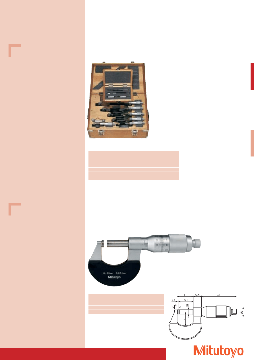
103–913–30
Series 103
As a set
Measuring
No.
Set Mass
range
combination
mm
g
0– 75
103–927–10
3 outside micrometers, 2 gauge blocks
750
0–150
103–913–30
6 outside micrometers, 5 gauge blocks
2435
0–300
103–914–30 12 outside micrometers, 11 gauge blocks 10130
150–300
103–915–10
6 outside micrometers, 6 gauge blocks
7695
Specifications
Graduation:
0,01 mm
Scales:
thimble and sleeve
satin chrome finish,
Measuring spindle: spindle pitch 0,5 mm
with spindle lock
Measuring surfaces: carbide-tipped,
precision ground and
micro-lap finish
Frame:
enamelled
Measuring force:
5–10 N
(from 100 mm: 5–15 N)
Including box, gauge block (from 25–600 mm),
up to 50 mm with factory certificate, key
40
Measuring range
No.
Inserts
Standards
Mass
mm
kg
0– 50
104–171
1
–
0,32
0– 100
104–139 A
4
3
0,79
0– 150
104–135 A
6
5
1,35
100– 200
104–140 A
4
4
1,38
150– 300
104–136 A
6
6
2,65
200– 300
104–141 A
4
4
2,22
300– 400
104–142 A
4
4
3,31
400– 500
104–143 A
4
4
4,81
500– 600
104–144 A
4
4
6,35
600– 700
104–145 A
4
4
7,72
700– 800
104–146 A
4
4
9,08
800– 900
104–147 A
4
4
10,41
900–1000
104–148 A
4
4
11,78
Measuring range
No.
Inserts
Protecton
Standards
Mass
mm
IP-65
kg
0– 150
340–251
6
5
0,96
150– 300
340–252
6
6
1,88
300– 400
340–513
4
–
4
3,31
400– 500
340–514
4
–
4
4,81
500– 600
340–515
4
–
4
6,35
600– 700
340–516
4
–
4
7,72
700– 800
340–517
4
–
4
9,08
800– 900
340–518
4
–
4
10,41
900–1000
340–519
4
–
4
11,78
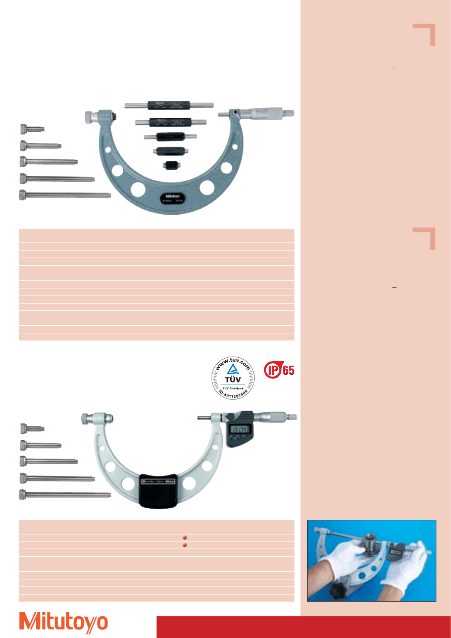
Series 340
“DIGIMATIC” Type,
with data output
DIN 863-1, Form D16
Outside Micrometer Special versions
• With exchangeable measuring anvil for a variable measuring range.
Specifications
Accuracy:
DIN 863-1 ab 500 mm
Factory specification
Error limit: (4 +
L
75
) mm; L in mm
Graduation:
0,01 mm
Scales:
thimble and sleeve
satin chrome finish,
Ø 18 mm (up to 300 mm)
Ø 21 mm (over 300 mm)
Measuring spindle: Ø 6,35 mm (up to 300 mm)
Ø 8 mm (over 300 mm)
spindle pitch 0,5 mm,
with spindle lock
Measuring surfaces: hardened, precision ground
Frame:
light weight construction,
enamelled
Measuring force:
5–10 N (10–14 N for range
of 300 mm and more)
Including box, standards, measuring inserts, key
Specifications
Protection class:
IP-65
(Measuring range up to 300 mm)
Accuracy:
DIN 863-1 ab 500 mm
Factory specification
Error limit: (4 +
L
75
) mm; L in mm
Resolution:
0,001 mm
Scales:
thimble and sleeve
satin chrome finish,
Ø 18 mm (up to 300 mm)
Ø 21 mm (over 300 mm)
Measuring spindle: Ø 6,35 mm (up to 300 mm)
Ø 8 mm (over 300 mm)
spindle pitch 0,5 mm,
with spindle lock
Measuring surfaces: hardened, precision ground
Frame:
light weight construction,
enamelled
Measuring force:
5–10 N (10–14 N for
measuring rage over 300 mm)
Including box, standards, measuring inserts,
key, 1 battery
Optional accessories
No. 05CZA662
Signal cable (1 m) (for devices up to
300 mm Measuring range)
No. 05CZA663
Signal cable (2 m) (for devices up to
300 mm Measuring range)
No. 937387
Signal cable (1 m) (for devices from
300 mm Measuring range)
No. 965013
Signal cable (2 m) (for devices from
300 mm Measuring range)
Consumable Spares
No. 938882
Battery SR-44
104–135 A
340–251
Series 104
DIN 863-1, Form D16
Measuring range up to 300 mm
41
Specifications
Accuracy:
Factory specification
Error limit: (6 +
L
75
) mm; L in mm
max. measuring length
Graduation:
0,01 mm
Scales:
thimble and sleeve
satin chrome finish,
Ø 21 mm
Measuring spindle: Ø 8 mm
spindle pitch 0,5 mm
Measuring surfaces: carbide-tipped, precision
ground, micro-lap finish
Frame:
light-weight welded,
enamelled
Measuring force:
5–10 N
Including box, standards (2 pieces),
adjustable stopper
Optional accessories
Standards supplied on order.
Control and adjustment of all outside micrometers
with a minimum measuring range of 1000 mm
see page 65
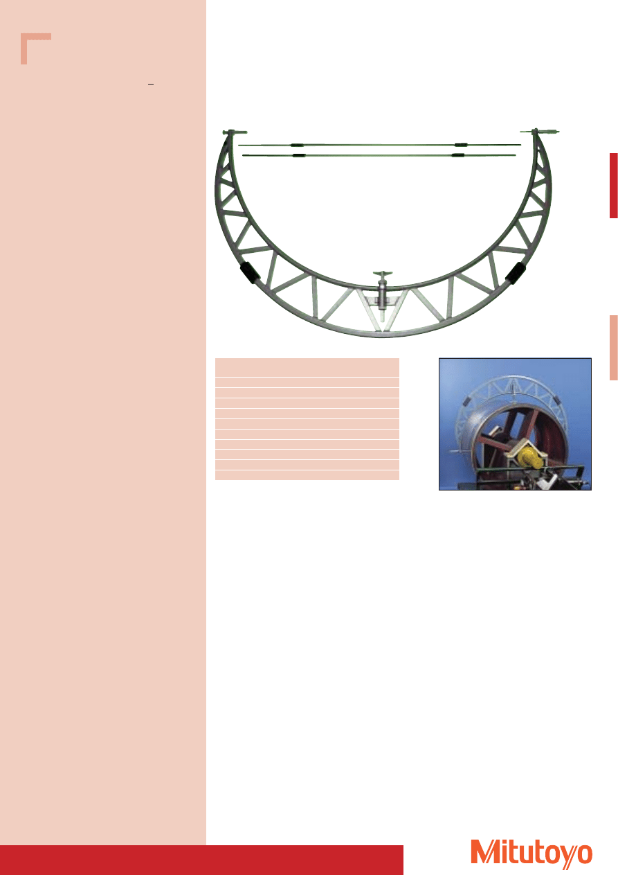
Outside Micrometer
• Stable and rugged light-weight construction of rectangular tube.
• The measuring of the outside micrometer is 50 mm.
Series 105
with adjustable anvil
105–411
Measuring range
No.
Mass
mm
kg
1000–1100
105–408
6,37
1100–1200
105–409
7,08
1200–1300
105–410
7,79
1300–1400
105–411
8,50
1400–1500
105–412
9,21
1500–1600
105–413
10,17
1600–1700
105–414
11,13
1700–1800
105–415
12,09
1800–1900
105–416
13,05
1900–2000
105–417
14,01
42
Outside Micrometer with Mechanical Counter
• Direct-reading outside micrometer for quick and easy reading.
Measuring range
No.
L
a
b
c
Mass
mm
mm
mm
mm
mm
g
100–125
193–305
132,8
5,3
17
79
670
125–150
193–306
158,2
5,7
19
94
825
150–175
193–307
183,6
6,1
19
106
885
175–200
193–308
208,8
6,3
18
118
1045
200–225
193–309
234,2
6,7
17
130
1175
225–250
193–310
259,0
5,5
18
143
1325
Specifications
Accuracy:
DIN 863-1
Graduation:
0,01 mm
Numerical increment
Register:
0,01 mm
Scales:
thimble and sleeve
satin chrome finish
Measuring spindle:
spindle pitch 0,5 mm
with spindle lock
Measuring surfaces: carbide-tipped,
precision ground and
micro-lap finish
Frame:
forged, enamelled
Measuring force:
5–15 N
Including box, gauge block from 25 mm, key
Series 193
DIN 863-1
Series 193
b
L
25.5
47
3
17
e
Ød
c
a
27.5
Measuring range
No.
L
a
b
c
d
e
Mass
mm
mm
mm
mm
mm
Ø mm
Ø mm
g
0– 25
193–101
30,0
2,5
5
26
6,35
18
224
25– 50
193–102
55,0
2,5
8
32
6,35
18
275
50– 75
193–103
80,0
2,5
9
45
6,35
18
379
75–100
193–104
105,0
2,5
9
57
6,35
18
489
193–101
193–901
Series 193
As a set
Measuring range
No.
Set combination
Mass
mm
g
0– 75
193–901
3 outside micrometers, 2 gauge blocks
878
0–100
193–902
4 outside micrometers, 3 gauge blocks
1367
0–150
193–908
6 outside micrometers, 5 gauge blocks
2862
Outside micrometers as a set
193–305
43
111–115
Spline Micrometer Special version
• With stepped measuring surfaces.
• For measuring grooves, splined shafts, recesses, shaped parts etc.
Series 111
DIN 863, Form D3
Measuring range
No.
/d
Mass
mm
mm
g
0– 25
111–115
10/3
205
25– 50
111–116
10/3
305
50– 75
111–117
10/3
370
75–100
111–118
10/3
500
0– 25
111–215
5/2
205
l
10 10
5
5
Ø3
Ø2
Specifications
Accuracy:
DIN 863-1
Graduation:
0,01 mm
Scales:
thimble and sleeve
satin chrome finish,
Ø 18 mm
Measuring spindle: Ø 6,35 mm,
spindle pitch 0,5 mm,
with spindle lock
Measuring surfaces: carbide-tipped,
precision ground,
micro-lap finish, stepped
Frame:
enamelled
Measuring force:
5–10 N
Including box, gauge block (25–100 mm), key
Measuring range
No.
/d
Mass
mm
mm
g
0– 25
331–251
10/3
330
25– 50
331–252
10/3
470
50– 75
331–253
10/3
625
75–100
331–254
10/3
565
0– 25
331–261
5/2
330
25– 50
331–262
5/2
470
50– 75
331–263
5/2
625
75–100
331–264
5/2
565
331–251
Specifications
Protection class:
IP-65
Accuracy:
DIN 863-1
Resolution:
0,001 mm
Scales:
thimble and sleeve
satin chrome finish,
Ø 18 mm
Measuring spindle: Ø 6,35 mm,
spindle pitch 0,5 mm,
with spindle lock
Measuring surfaces: carbide-tipped,
precision ground,
micro-lap finish, stepped
Frame:
enamelled
Measuring force:
5–10 N
Including box, gauge block (25–75 mm), key,
1 battery
Optional accessories
No. 05CZA662
Signal cable (1 m)
No. 05CZA663
Signal cable (2 m)
Consumable Spares
No. 938882
Battery SR-44
Series 331
“DIGIMATIC” Type, with data output
DIN 863, Form D3
l
44
Specifications
Accuracy:
Factory specification
Error limit: (2 + L/75) mm
L in mm
Graduation:
0,01 mm
Scales:
thimble and sleeve
satin chrome finish,
Ø 18 mm
Measuring spindle: Ø 6,35 mm,
spindle pitch 0,5 mm,
with spindle lock
Measuring surfaces: hardened and precision ground,
conical spindle and anvil,
measuring point radius 0,3 mm
Frame:
enamelled
Measuring force:
5–10 N
Including box, gauge block (25–100 mm), key
Specifications
Protection class:
IP-65
Accuracy:
Factory specification
Error limit: (2 + L/75) mm
L in mm
Resolution:
0,001 mm
Scales:
thimble and sleeve
satin chrome finish,
Ø 18 mm
Measuring spindle: Ø 6,35 mm,
spindle pitch 0,5 mm,
with spindle lock
Measuring surfaces: hardened and precision ground,
conical spindle and anvil,
measuring point radius 0,3 mm
Frame:
enamelled
Measuring force:
5–10 N
Including box, gauge block (25–75 mm), key,
1 battery
Optional accessories
No. 05CZA662
Signal cable (1 m)
No. 05CZA663
Signal cable (2 m)
Consumable Spares
No. 938882
Battery SR-44
Point Type Micrometer Special version
• With pointed spindle.
• For measuring grooves, steps etc.
Series 112
Analogue version
Measuring
No.
L
a
b
c
Ød
Mass
range
mm
mm mm mm mm mm
g
Angle: 15°
0–25
112–153 55,3 12,8 10
38 6,35
205
25–50
112–154 80,3 12,8 12
49 6,35
305
Angle: 30°
0–25
112–201 55,3 12,8 10
38 6,35
205
25–50
112–202 80,3 12,8 12
49 6,35
305
17
47
14.5
L
b
42.5
a
3
Ød
c
Measuring
No.
Mass
range
mm
g
Angle: 15°
0– 25
342–251
330
25– 50
342–252
470
50– 75
342–253
625
75–100
342–254
565
Angle: 30°
0– 25
342–261
330
25– 50
342–262
470
50– 75
342–263
625
75–100
342–264
565
Series 342
“DIGIMATIC” Type, with data output
15
°
30
°
342–251
112–201
15
°
30
°
45
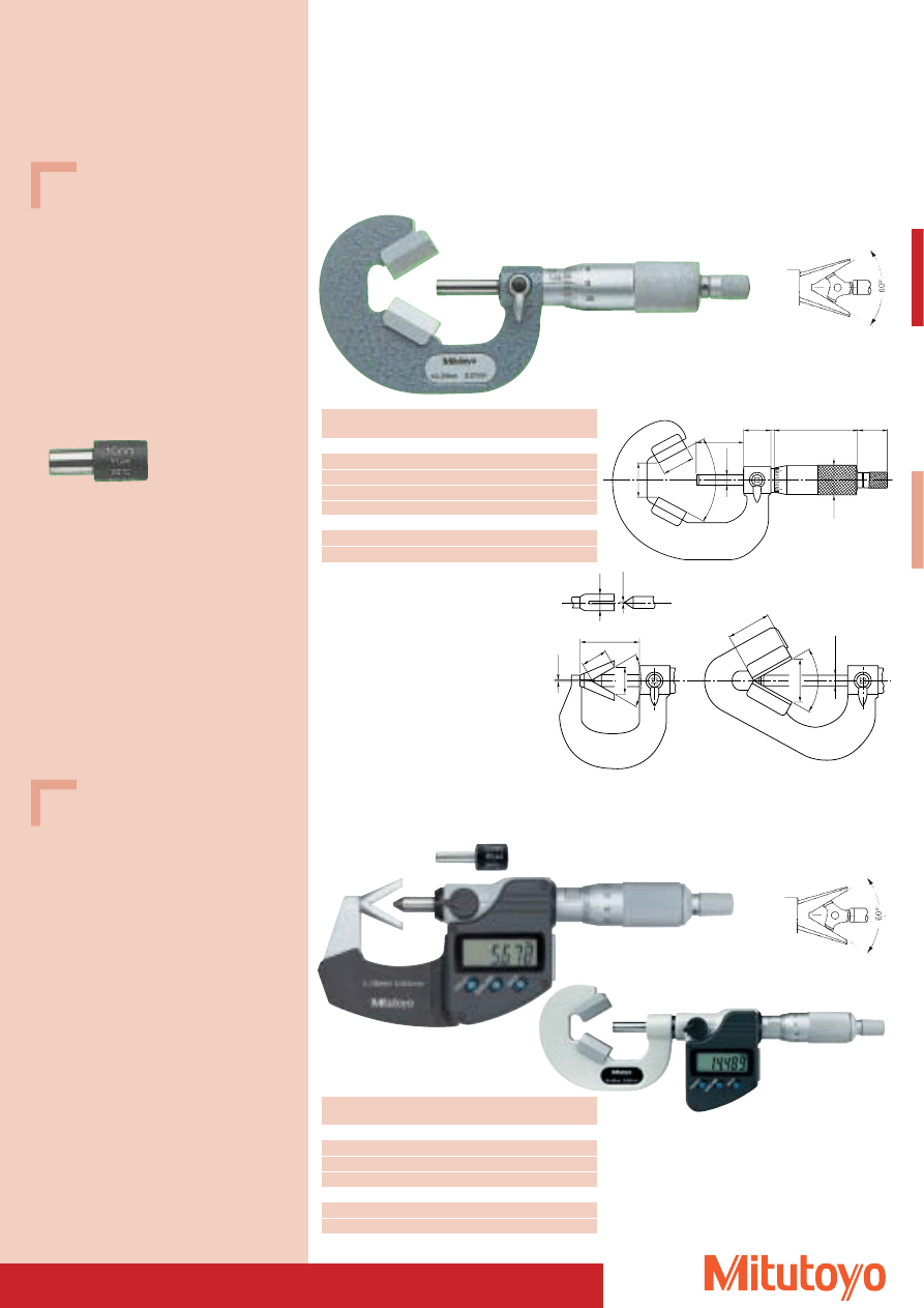
Outside Micrometer Special version
• With V-anvil.
• For 3 fluted measurements on taps, drills, reamers etc.
114–102
47
17
3
Ø18
14.5
Ø
6.35
27.5
18
60
°
A
(14.7)
0.5
14.5
60
°
8
Ø1.5
22.7
(23.46)
Ø
6.35
60
°
30.3
Series 314
“DIGIMATIC” Type, with data output
DIN 863, Form D 10–3
114–101
114–204
Series 114
DIN 863, Form D 10–3
Specifications
Accuracy:
DIN 863-1
Graduation:
0,01 mm
Scales:
thimble and sleeve
satin chrome finish,
Ø 18 mm
Measuring spindle: Ø 6,35 mm,
spindle pitch 0,75 mm,
with spindle lock
Measuring surfaces: Prism angle 60°
Frame:
enamelled
Measuring force:
5–10 N
Including box, gauge block, key
Gauge blocks (Standard accessories)
No. 167–327
Ø 5 mm
No. 167–328
Ø 10 mm
No. 167–329
Ø 25 mm
Specifications
Accuracy:
DIN 863-1
Resolution:
0,001 mm
Scales:
thimble and sleeve
satin chrome finish,
Ø 18 mm
Measuring spindle: Ø 6,35 mm,
spindle pitch 0,75 mm,
with spindle lock
Measuring surfaces: Prism angle 60°
Frame:
enamelled
Measuring force:
5–10 N,
3–8 N (314–251, 314–261)
Including box, gauge block, key, 1 battery
(gauge blocks: see above)
Optional accessories
No. 05CZA662
Signal cable (1 m)
No. 05CZA663
Signal cable (2 m)
Consumable Spares
No. 938882
Battery SR-44
114–102
* Anvil carbide-tipped
Measuring range
No.
A
Mass
mm
mm
g
Measuring surfaces with grooves
1–15
114–101
0,5
120
10–25
114–102
6,2
280
25–40
114–103
19,14
400
2,3–25
114–204*
0,5
290
Measuring surfaces without grooves
1–15
114–161
0,5
120
10–25
114–162
6,2
280
314–251
314–252
Measuring range
No.
Mass
mm
g
Measuring surfaces with grooves
1–15
314–251
275
10–25
314–252
410
25–40
314–253
465
Measuring surfaces without grooves
1–15
314–261
275
10–25
314–262
410
46
Specifications
Accuracy:
DIN 863-1
Graduation:
0,01 mm
Scales:
thimble and sleeve
satin chrome finish,
Ø 18 mm
Measuring spindle: Ø 6,35 mm,
with spindle lock
Measuring surfaces: Prism angle 108°
Frame:
enamelled
Measuring force:
5–10 N
Including box, gauge block, key
Specifications
Accuracy:
DIN 863-1 (Type A, Type B)
Factory specification
Error limit: 3 mm (Type C)
Graduation:
0,01 mm
Scales:
thimble and sleeve
satin chrome finish,
Ø 18 mm
Measuring spindle: Ø 6,35 mm,
spindle pitch 0,5 mm,
with spindle lock
Measuring surfaces: carbide-tipped,
precision ground,
micro-lap finish
Frame:
enamelled
Measuring force:
5–10 N
Including box, gauge block (from 25–50 mm), key
Outside Micrometer Special version
Series 114
DIN 863, Form D 10–5
For 5 fluted measurements on taps, drills, reamers etc.
Measuring range
No.
Mass
mm
g
Measuring surfaces with grooves
5,0–25
114–121
255
25,0–45
114–122
400
2,3–25
114–137*
220
Measuring surfaces without grooves
5,0–25
114–165
255
* Anvil carbide-tipped
115–215
Type A
Type B
Type C
Series 115
DIN 863, Form D 1 (Type A, Type B) / Form similar to D12 (type C)
For measurements of all curved surfaces and wall thickness of tubes, bearings, rings etc.
Measuring
No.
Error limit
L
min. Ø d
Mass
range mm
mm
mm
mm
g
0– 25
115–115
3
–
10
180
25– 50
115–116
3
–
11
240
50– 75
115–117
3
–
17
315
75–100
115–118
4
–
18
375
0– 25
115–215
3
–
10
180
25– 50
115–216
3
–
11
240
50– 75
115–217
3
–
17
315
75–100
115–218
4
–
18
375
0– 25
115–302*
3
4
2
180
* spindle only carbide-tipped
Ød
L
Ød
5mm
SR4
Ød
5mm
SR4
114–121
Gauge blocks (Standard accessories)
No. 167–327
Ø 5 mm
No. 167–328
Ø 10 mm
No. 167–329
Ø 25 mm
7,5
7,5
47
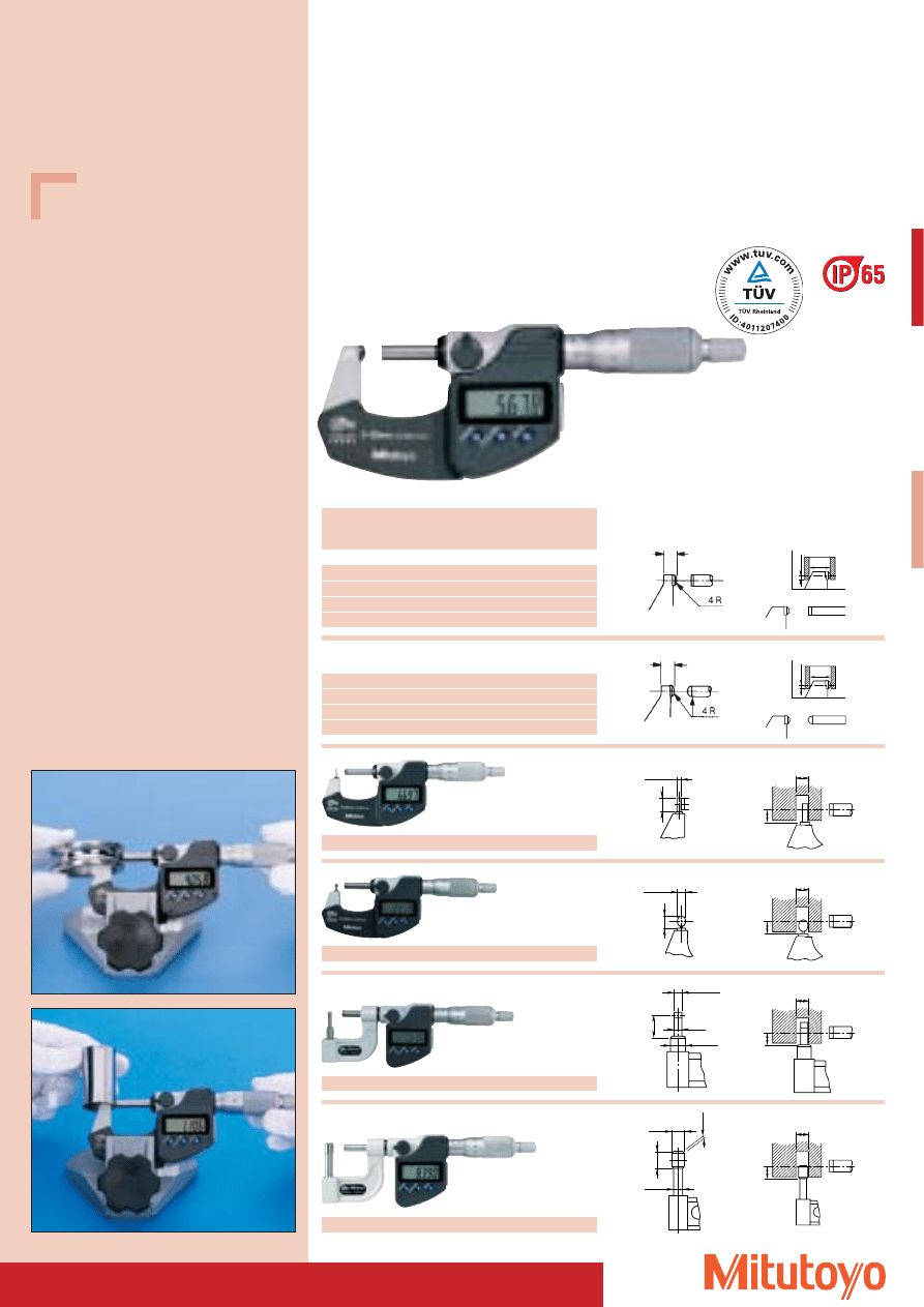
Specifications
Protection class:
IP-65
Accuracy:
DIN 863-1 (Type A, B),
Factory specification
Error limit: 3 mm
(Type C, D, E, F)
Resolution:
0,001 mm
Scales:
thimble and sleeve
satin chrome finish,
Ø 18 mm
Measuring spindle: Ø 6,35 mm,
spindle pitch 0,5 mm,
with spindle lock
Measuring surfaces: carbide-tipped,
precision ground,
micro-lap finish
Frame:
enamelled
Measuring force:
5–10 N*, 3–8 N**
Including box, gauge block (from 25–100 mm),
key, 1 battery
Optional accessories
No. 05CZA662
Signal cable (1 m)
No. 05CZA663
Signal cable (2 m)
Consumable Spares
No. 938882
Battery SR-44
Type A
Type B
Series 395
“DIGIMATIC” Type, with data output
DIN 863, Form D 1 (Type A, B), Form similar to D12 (types C, D, E, F)
For measurements of all curved surfaces and wall thickness
of tubes, bearings, rings etc.
0– 25
395–271*
2
–
15
9
270
25– 50
395–272*
2
–
15
9,8
330
50– 75
395–273*
2
–
19
12,6
470
75–100
395–274*
3
–
20
14
625
Measuring
No.
Error
L
min.
a
Mass
range
limits
Ø d
mm
mm
mm
mm
mm
g
0– 25
395–251*
2
–
15
9
270
25– 50
395–252*
2
–
15
9,8
330
50– 75
395–253*
2
–
19
12,6
470
75–100
395–254*
3
–
20
14
625
395—251
Tube Micrometer Special version
a
a
Ød
L
Ød
L
Ød
L
Ød
L
8
Ø1.8
6
SØ3.5
SØ4.7
Ø6.9
12.7
Ø4
9
Ø6.9
1.4
Ø8
Type C
Type D
Type E
Type F
Ød
5mm
SR4
Ød
5mm
SR4
0– 25
395–262**
3
4
3,6
–
270
0– 25
395–261**
3
4
2
–
270
0– 25
395–263**
3
12
4,8
–
310
0– 25
395–264**
3
22
8,2
–
310
48
Specifications
Accuracy:
Factory specification
Graduation:
0,01 mm
Scales:
thimble and sleeve
satin chrome finish,
Ø 18 mm
Measuring spindle: Ø 6,35 mm,
spindle pitch 0,5 mm,
with spindle lock
Frame:
enamelled
Measuring force: 5–10 N
Including box, gauge block (25–300 mm), insulation,
key
Specifications
Protection class:
IP-65
Accuracy:
Factory specification
Resolution:
0,001 mm
Scales:
thimble and sleeve
satin chrome finish,
Ø 18 mm
Measuring spindle: Ø 6,35 mm,
spindle pitch 0,5 mm,
with spindle lock
Frame:
enamelled
Measuring force: 3–8 N
Including box, gauge block (25–100 mm), insulation,
key, 1 battery
Optional accessories
No. 05CZA662
Signal cable (1 m)
No. 05CZA663
Signal cable (2 m)
Consumable Spares
No. 938882
Battery SR-44
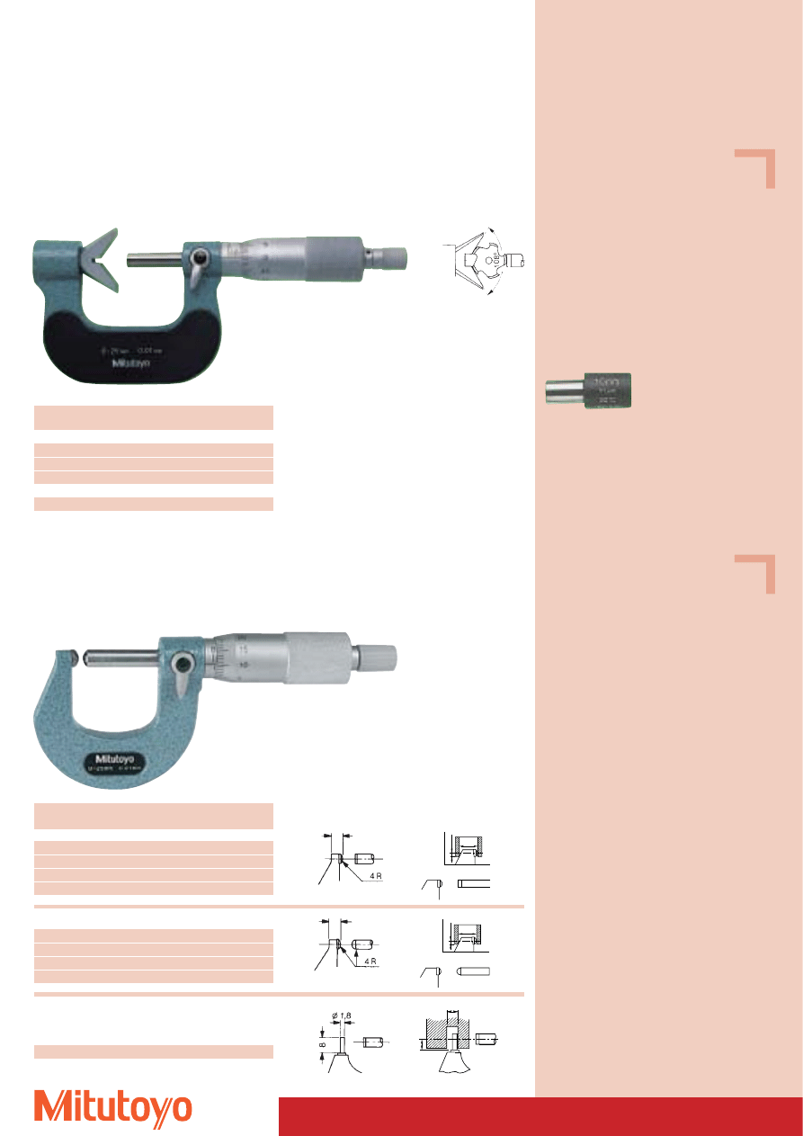
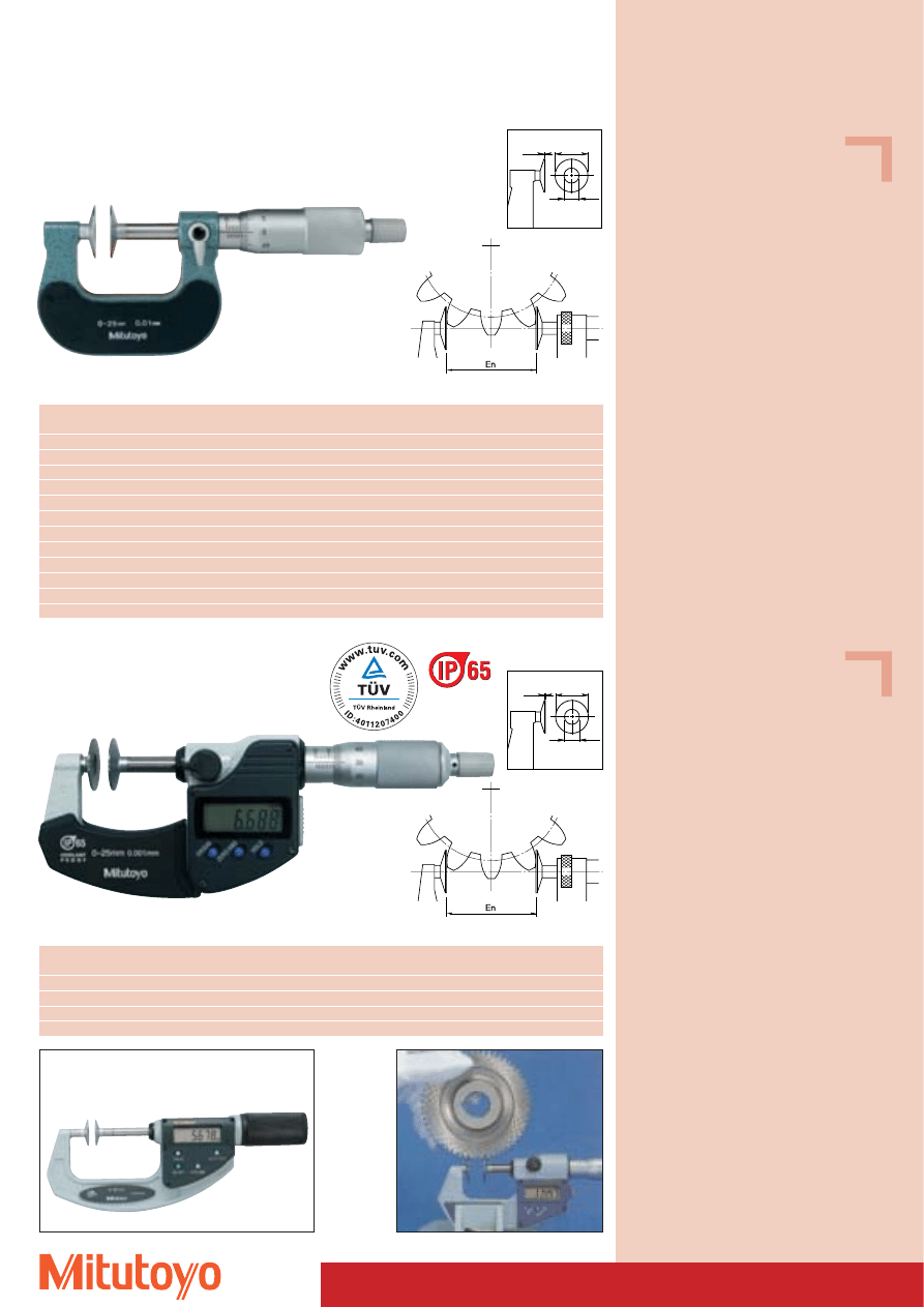
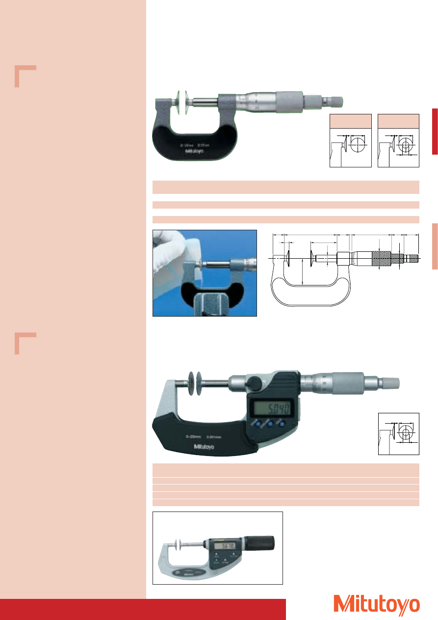
Outside Micrometer Special version
• With disc-shaped measuring surfaces.
• For measuring base tangent length, module 0,5 to 6, and to measure recess distances
Series 123
DIN 863, Form D 7
Measuring range
No.
Parallelism
Error limit
Ø d
Ø e
t
Mass
mm
mm
mm
mm
mm
mm
g
0– 25
123–101
4
4
20
8
0,7
200
25– 50
123–102
4
4
20
8
0,7
250
50– 75
123–103
6
6
20
8
0,7
300
75–100
123–104
6
6
20
8
0,7
375
100–125
123–105
7
7
30
12
1,0
520
125–150
123–106
7
7
30
12
1,0
570
150–175
123–107
7
8
30
12
1,0
730
175–200
123–108
8
8
30
12
1,0
890
200–225
123–109
8
8
30
12
1,0
1000
225–250
123–110
8
9
30
12
1,0
1200
250–275
123–111
9
9
30
12
1,0
1410
275–300
123–112
9
9
30
12
1,0
1680
Measuring range
No.
Parallelism
Error limit
Ø d
Ø e
t
Mass
mm
mm
mm
mm
mm
mm
g
0– 25
323–250
4
4
20
8
0,7
290
25– 50
323–251
4
4
20
8
0,7
355
50– 75
323–252
6
6
20
8
0,7
555
75–100
323–253
6
6
20
8
0,7
610
323–250
Series 323
“DIGIMATIC” Type, with data output
DIN 863, Form D 7
123–101
EN = tooth width over 3 teeth
EN = tooth width over 3 teeth
t
Ød
Øe
t
Ød
Øe
A Quick Outside Micrometer
see page 33
369–250
49
Outside Micrometer Special version
• With non-rotating spindle and disc-shaped measuring surfaces.
• For measuring felt, rubber, cardboard, fabric etc.
Series 169
DIN 863, Form D 6
Measuring range
No.
Mass
mm
g
0– 25
369–250
340
25– 50
369–251
480
50– 75
369–252
635
75–100
369–253
775
Series 369
“DIGIMATIC” Type, with data output
DIN 863, Form D 6
169–201
47
15.5
3
L
b
14.5
a
31.5
Ø18
Ød
c
17
Ø12
t
Ø14.3
Specifications
Accuracy:
DIN 863-1
Graduation:
0,01 mm
Scales:
thimble and sleeve
satin chrome finish,
Ø 18 mm
Measuring spindle: Ø 8 mm,
spindle pitch 0,5 mm,
with spindle lock
Frame:
enamelled
Measuring force: 5–10 N
Including box, insulation, key
Specifications
Accuracy:
DIN 863-1
Resolution:
0,001 mm
Scales:
thimble and sleeve
satin chrome finish,
Ø 18 mm
Measuring spindle: Ø 6,35 mm,
spindle pitch 0,5 mm,
with spindle lock
Frame:
enamelled
Measuring force: 3–8 N
Including box, gauge block (25–100 mm),
insulation, key, 1 battery
Optional accessories
No. 05CZA662
Signal cable (1 m)
No. 05CZA663
Signal cable (2 m)
Consumable Spares
No. 938882
Battery SR-44
0.7
Ø20
Ø8
169–101 with holohedral measuring surfaces
A Quick Outside Micrometer
see page 33
Measuring range
No.
L
a
b
c
Ø d
t
Mass
mm
mm
mm
mm
mm
mm
mm
g
With continuous measuring surfaces
0–25
169–101
37,5
6
14
25
8
0,4
230
With offset measuring surfaces
0–25
169–201
37,5
6
14
25
8
0,7
230
169–101
Continuous
measuring surfaces
t
Ø20
Ø8
169–201
Offset
measuring surfaces
50
Specifications
Accuracy:
DIN 863-1
Graduation:
0,01 mm
Scales:
thimble and sleeve
satin chrome finish,
Ø 18 mm
Measuring spindle: Ø 6,35 mm,
spindle pitch 0,5 mm
Frame:
enamelled
Measuring force: 5–10 N
Including box, gauge block (from 25 mm), insulation,
key
Specifications
Accuracy:
DIN 863-1
Resolution:
0,001 mm
Scales:
thimble and sleeve
satin chrome finish,
Ø 18 mm
Measuring spindle: Ø 6,35 mm,
spindle pitch 0,5 mm
Frame:
enamelled
Measuring force: 3–8 N
Including box, gauge block (from 25 mm), insulation,
key, 1 battery
Optional accessories
No. 05CZA662
Signal cable (1 m)
No. 05CZA663
Signal cable (2 m)
Consumable Spares
No. 938882
Battery SR-44
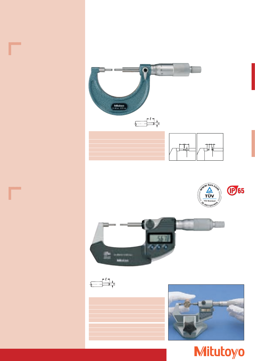
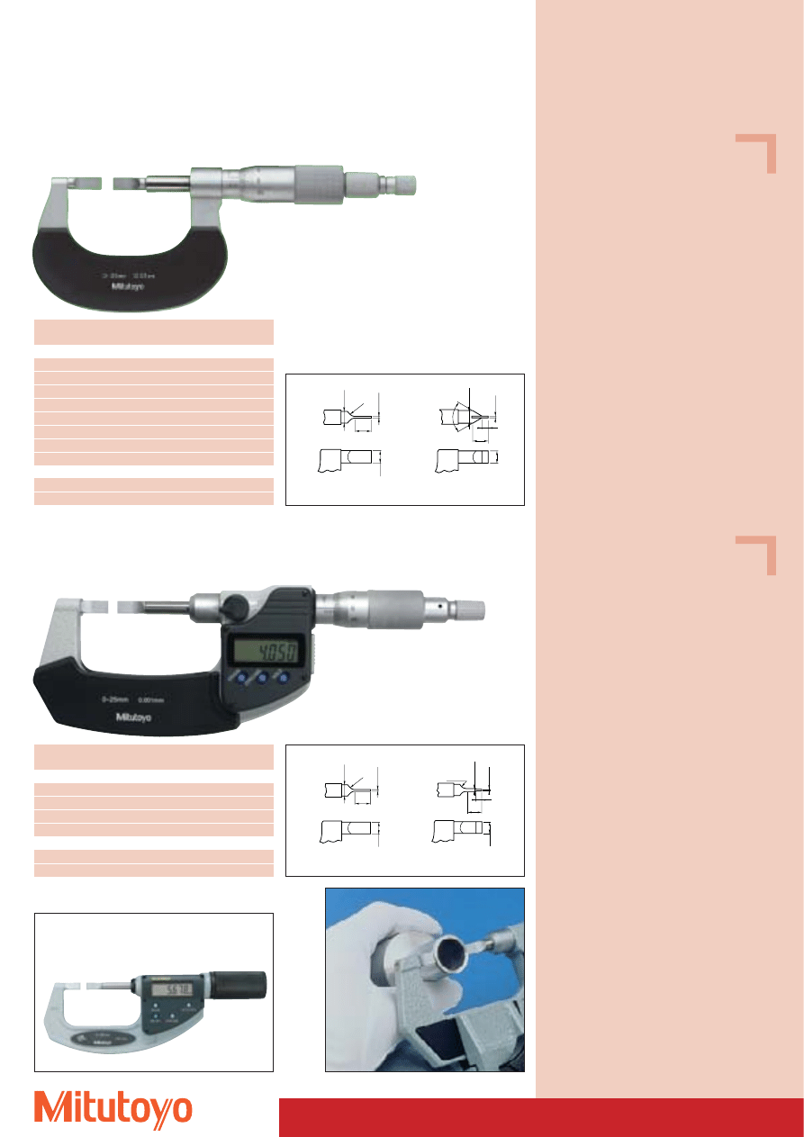
Blade Micrometer Special version
• With small measuring surfaces.
• For measuring small external grooves.
• Non-rotating spindle.
Series 122
DIN 863, Form D 4
Measuring range
No.
Mass
mm
g
Type A
0– 25
122–101
260
25– 50
122–102
300
50– 75
122–103
360
75–100
122–104
525
100–125
122–105
–
125–150
122–106
–
150–175
122–107
–
175–200
122–108
–
Type D, with carbide-tipped measuring faces
0– 25
122–141
275
25– 50
122–142
315
Measuring range
No.
Mass
mm
g
Type A
0– 25
422–230
365
25– 50
422–231
565
50– 75
422–232
465
75–100
422–233
580
Type B
0– 25
422–260
365
25– 50
422–261
565
122–101
6.5
Ø6
0.75
R8
Ø6
60
°
Ø6
0.4
4
8
6
Type A
Type D
A Quick Micrometer
see page 34
422–230
Series 422
“DIGIMATIC” Type, with data output
DIN 863, Form D 4
6.5
Ø6
0.75
R8
Ø6
0.75
0.4
R8
3
6.5
Ø6
Type A
Type B
51
Specifications
Accuracy:
Factory specification
Error limit: 3 mm
Graduation:
0,01 mm
Scales:
thimble and sleeve
satin chrome finish,
Ø 18 mm
Measuring spindle: Ø 6,35 mm,
spindle pitch 0,5 mm,
with spindle lock
Measuring surfaces: hardened and
precision ground
Frame:
enamelled
Measuring force:
5–10 N
Including box
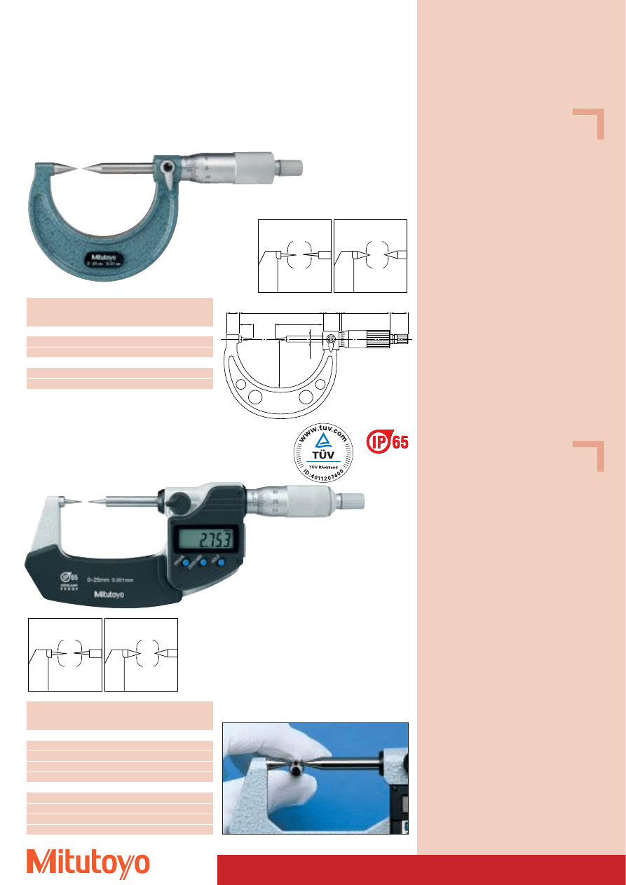
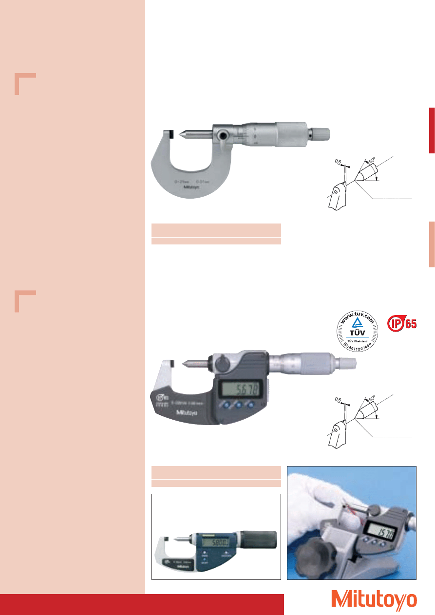
Point Type Micrometer Special version
• With pointed spindle.
• For measuring crimp heights.
Series 112
Analogue version
112–401
Measuring range
No.
Mass
mm
g
0–25
112–401
165
Ø 0,5 mm Flat tip
A Quick Micrometer
see page 34
Specifications
Protection class:
IP-65
Accuracy:
DIN 863-1
Error limit: 3 mm
Resolution:
0,001 mm
Scales:
thimble and sleeve
satin chrome finish,
Ø 18 mm
Measuring spindle: Ø 6,35 mm,
spindle pitch 0,5 mm,
with spindle lock
Measuring surfaces: hardened and
precision ground
Frame:
enamelled
Measuring force:
3–8 N
Including box, 1 battery
Optional accessories
No. 05CZA662
Signal cable (1 m)
No. 05CZA663
Signal cable (2 m)
Consumable Spares
No. 938882
Battery SR-44
342–271
Series 342
“DIGIMATIC” Type, with data output
for measuring crimp heights
Measuring range
No.
Mass
mm
g
0–20
342–271
270
Ø 0,5 mm Flat tip
52
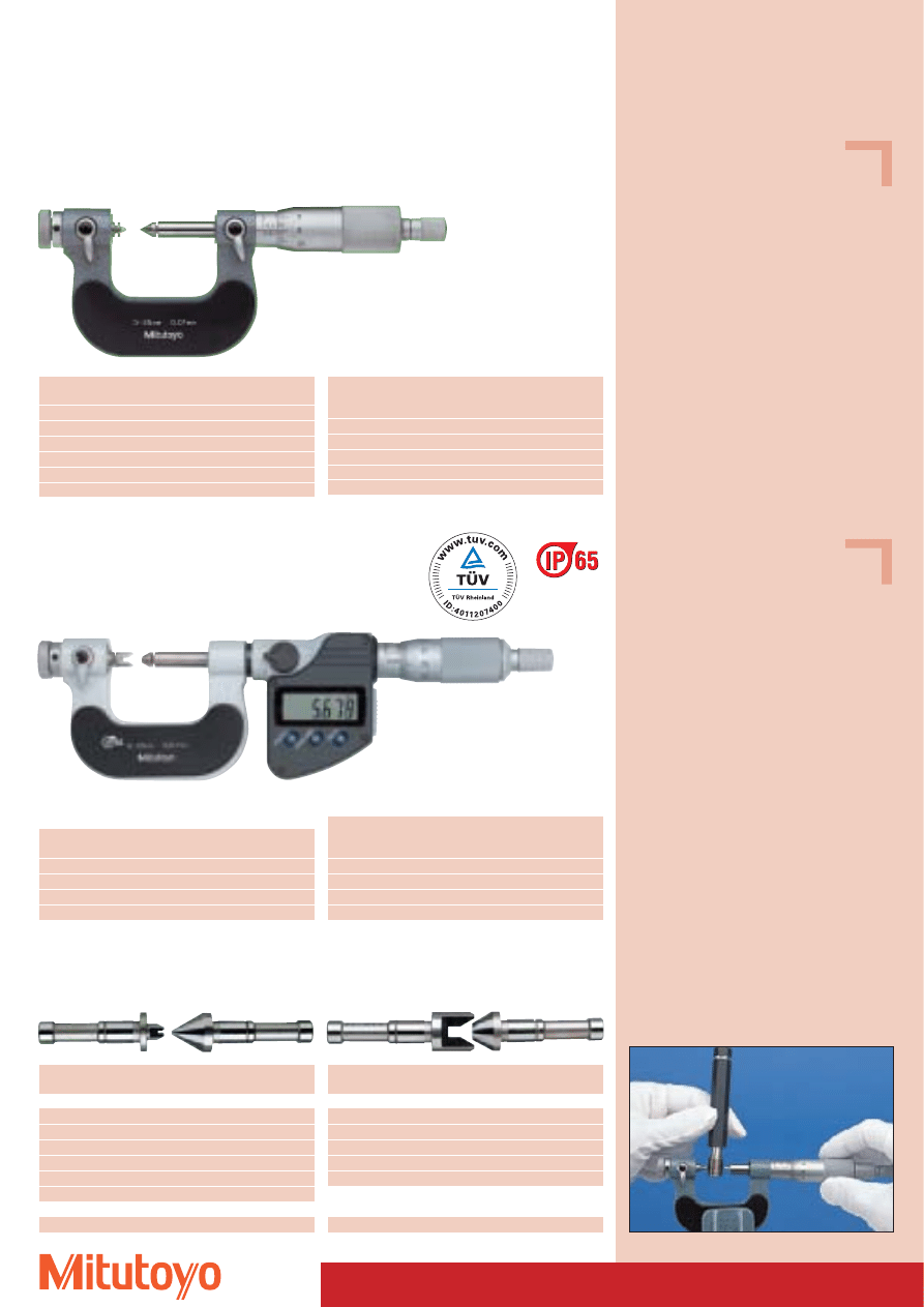
Screw Thread Micrometer Special version
• For measuring the pitch diameter of threads.
Series 126
DIN 863, Form D 18
Measuring range
No.
Mass
mm
g
0– 25
126–125
240
25– 50
126–126
290
50– 75
126–127
390
75–100
126–128
450
100–125
126–129
530
125–150
126–130
620
Length
No.
No.
55°
60°
(Optional accessories) (Standard accessories)
25 mm
167–272
167–261
50 mm
167–273
167–262
75 mm
167–274
167–263
100 mm
167–275
167–264
125 mm
167–276
167–265
No.
Metric
UNF
pitch
turns / inch
Individual measuring inserts
126–801
0,4–0,50
64,0–48,0
126–802
0,6–0,90
44,0–28,0
126–803
1,0–1,75
24,0–14,0
126–804
2,0–3,00
13,0– 9,0
126–805
3,5–5,00
8,0– 5,0
126–806
5,5–7,00
4,5– 3,5
Measuring insert set
126–800
(consists of No. 126–801 to 126–806)
No.
Whitworth
No.
Whitworth
turns / inch
turns / inch
Individual measuring inserts
126–811
60–48
126–816
18,0–14,0
126–812
48–40
126–817
14,0–10,0
126–813
40–32
126–818
10,0– 7,0
126–814
32–24
126–819
7,0– 4,5
126–815
24–18
126–820
4,5– 3,5
Measuring insert set
126–810
(consists of No. 126–811 to 126–820)
326–251
Series 326
“DIGIMATIC” Type, with data output
DIN 863, Form D 18
Series 126 / 326
Optional accessories measuring inserts
126–125
Measuring inserts
Length
No.
No.
55°
60°
(Optional accessories) (Standard accessories)
25 mm
167–272
167–261
50 mm
167–273
167–262
75 mm
167–274
167–263
100 mm
167–275
167–264
Measuring inserts
Measuring range
No.
Mass
mm
g
0– 25
326–251
350
25– 50
326–252
380
50– 75
326–253
470
75–100
326–254
510
Specifications
Accuracy:
DIN 863-1
Graduation:
0,01 mm
Scales:
thimble and sleeve
satin chrome finish,
Ø 18 mm
Measuring spindle: Ø 6,35 mm,
spindle pitch 0,5 mm,
with spindle lock
Frame:
enamelled
Measuring force: 5–10 N
Including box, gauge block (60°), insulation, key
Measuring inserts not included
Specifications
Protection class:
IP-65
Accuracy:
DIN 863-1
Resolution:
0,001 mm
Scales:
thimble and sleeve
satin chrome finish,
Ø 18 mm
Measuring spindle: Ø 6,35 mm,
spindle pitch 0,5 mm,
with spindle lock
Frame:
enamelled
Measuring force: 5–10 N
Including box, gauge block (60°), insulation,
key, 1 battery
Measuring inserts not included
Optional accessories
No. 05CZA662
Signal cable (1 m)
No. 05CZA663
Signal cable (2 m)
Consumable Spares
No. 938882
Battery SR-44
53
“DIGIMATIC” Gear Micrometer Special version
• With exchangeable ball inserts.
• For measuring divided circles or indirect tooth thickness on straight or helical teeth.
Series 324
“DIGIMATIC” Type, with data output
DIN 863, Form D 1
324–251
Series 324
Optional accessories (measuring inserts)
No.
Ball
Module
Ø mm
124–801
0,8
0,50–0,55
124–802
1,0
0,60–0,65
124–821
1,5
0,90–1,00
124–805
2,0
1,25
124–822
2,5
1,50
124–807
3,0
1,75
124–823
3,5
2,00
124–810
4,0
2,25
124–824
4,5
2,50
124–812
5,0
2,75
124–814
6,0
3,50
124–816
7,0
4,00
124–819
8,0
4,75
Further inserts see page 52
Measuring range
No.
Mass
mm
g
0– 25
324–251
400
25– 50
324–252
490
50– 75
324–253
530
75–100
324–254
600
Specifications
Protection class:
IP-65
Accuracy:
DIN 863-1
Resolution:
0,001 mm
Scales:
thimble and sleeve
satin chrome finish,
Ø 18 mm
Measuring spindle: Ø 6,35 mm
Frame:
enamelled
Measuring force: 5–10 N
Including box, key, 1 battery
Measuring inserts not included
Optional accessories
No. 05CZA662
Signal cable (1 m)
No. 05CZA663
Signal cable (2 m)
Consumable Spares
No. 938882
Battery SR-44
54
Specifications
Accuracy:
DIN 863-1
Graduation:
0,01 mm on micrometer
Scales:
thimble and sleeve
satin chrome finish,
Ø 18 mm
Measuring spindle: Ø 6,35 mm
spindle pitch 0,5 mm,
with spindle lock
Measuring surfaces: carbide-tipped,
micro-lap finish
Frame:
enamelled
anvil:
3 mm abhebbar
Measuring force:
5–10 N
Including box, gauge block (from 25–50 mm),
insulation, key
Outside Micrometer Special version
• For series tests.
Series 107
DIN 863, Form D14
Measuring process: an basic dimension is set on the micrometer. Then the spindle is locked and the
workpiece inserted. The moveable anvil transmits the plus-minus tolerance which can then be read
from the dial indicator.
107–201
with dial 2046 SB
(optional accessories)
Measuring range
No.
Mass
mm
without dial
g
0–25
107–201
480
25–50
107–202
520
No. 543–250 B
Optional accessories
(At user’s discretion)
No. 543–690 B
1 mm
No. 2109 SB–10
1 mm
No. 2900 SB–10
1 mm
No. 524–501
1 mm
0,5 mm
No. 542–144
0,1 mm
10 mm
No. 2972
1 mm
No. 524–500
28,5
27,5
14,5
53,5
Operating
lever
523–141
Sample application: 523–141 + 543–250 B
55
Micrometer stands
see pages 68 and 69
Specifications
Accuracy:
Factory specification
Measuring surfaces: carbide-tipped,
precision ground,
micro-lap finish, Ø 8 mm
Including box, workpiece rest
Optional accessories
(At user’s discretion)
No. 543–250 B
DIGIMATIC Dial Indicator ID-C
No. 543–690 B
DIGIMATIC Dial Indicator ID-S
No. 542–144
Linear Gage Probe
Resolution 0,1 mm
No. 2972
Analogue Dial Indicator
No. 2900 SB–10
Analogue Dial Indicator
No. 2110 SB–10
Analogue Dial Indicator
No. 524–501
Dial Indicator
No. 524–500
Dial Indicator
See page 54
Specifications
Accuracy:
Factory specification
Error limit dial indicator: 1 mm
Graduation dial indicator: 0,001 mm
Indication dial indicator: ± 0,06 mm
Measuring surfaces:
carbide-tipped,
precision ground,
micro-lap finish
Flatness:
0,3 mm
Measuring force:
5–10 N
Protection class:
IP-54
Including box, workpiece support
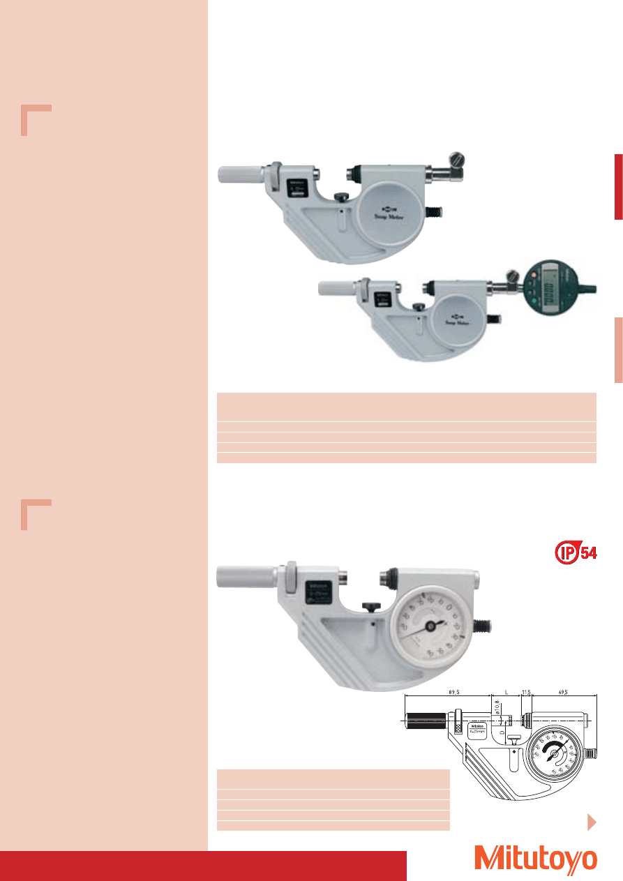
Passameter
• Passameters are adjustable snap gauges, applicable for serial measurements of rotational symmetric
workpieces such as shafts, axes, bolts, etc. as well as for thickness and length measurements.
Series 523
Passmeter with dial indicator
Return motion lever in a handy position
Measuring range
No.
Free lift
Flatness
Parallelism
Error limits
Measuring force
Mass
(Transmission element)
mm
mm
mm
mm
mm
N
g
0– 25
523–141
2
0,3
0,6
0,4
5–10
710
25– 50
523–142
2
0,3
0,6
0,4
5–10
810
50– 75
523–143
2
0,3
1,0
0,4
5–10
920
75–100
523–144
2
0,3
1,0
0,4
5–10
1050
Measuring range
No.
Parallelism
L
D
Mass
mm
mm
mm
mm
g
0– 25
523–121
0,6
31
25,0
740
25– 50
523–122
0,6
56
35,0
840
50– 75
523–123
1,0
81
47,5
950
75–100
523–124
1,0
106
60,0
1080
Series 523
Passameter with dial indicator
Incl. tolerance markings for serial measurements
With anvil retraction button in handy position
523–121
56
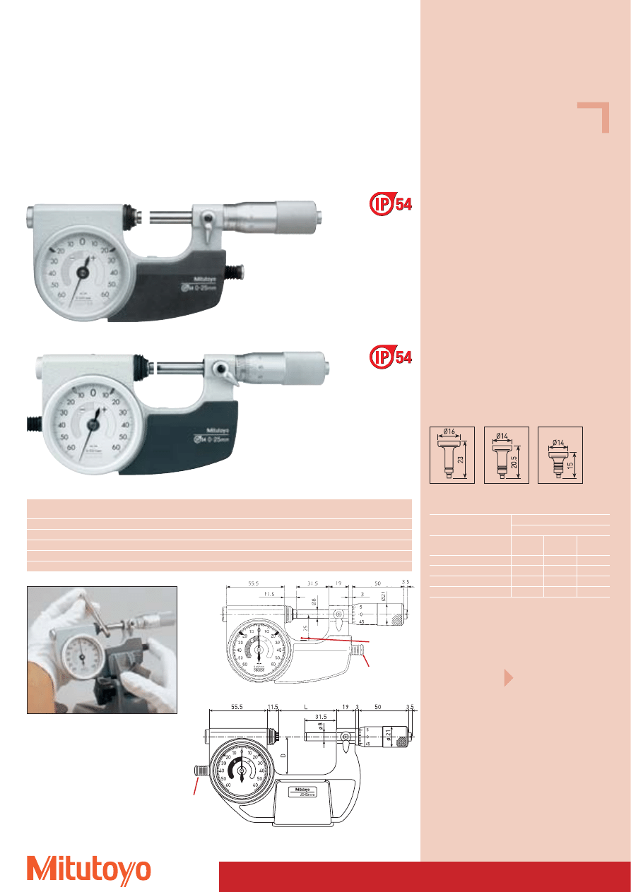
Indicating Micrometer Special version
• Fine pointer micrometer.
• For series tests.
Series 510
DIN 863, Form D 13
Large size dial indicator for easy reading
Featuring Zero setting, tolerance marks for GO/NG measurements
Retracting button easy to operate
Micrometer stands
see pages 68 and 69
Specifications
Accuracy:
Factory specification
Graduation dial indicator: 0,001 mm
Graduation micrometer: 0,001 mm (Nonius)
Error limit dial indicator: 1 mm
Error limit micrometer:
3 mm
Indication range
dial indicator:
± 0,06 mm
Scales:
thimble and sleeve
satin chrome finish
Measuring surfaces:
carbide-tipped,
precision ground,
micro-lap finish
Flatness:
0,3 mm
Measuring force:
5–10 N
Protection class:
IP-54
Including box, gauge block (from 25 mm), key
Optional accessories
No. 04AZA124
Workpiece support A
No. 04AZA125
Workpiece support B
No. 04AZA126
Workpiece support C
Fits diameter
Workpiece support
Measuring
No.
A
B
C
range mm
Ø mm
Ø mm
Ø mm
0– 25
510–121
–
4–16
15– 25
25– 50
510–122
25–37
30–42
41– 50
50– 75
510–123
50–61
54–66
65– 75
75–100
510–124
75–87
80–92
91–100
Measuring range 0–25 mm
Workpiece
support optional
Measuring range 25–100 mm
No. 04AZA124 No. 04AZA125 No. 04AZA126
Measuring range
No.
Function-
Parallelism
L
D
Mass
mm
key
mm
mm
mm
g
0– 25
510–121
right
0,6
31,5
25
520
0– 25
510–141
left
0,6
31,5
25
520
25– 50
510–122
left
0,6
38,0
56
670
50– 75
510–123
left
1,0
50,0
81
820
75–100
510–124
left
1,0
63,0
106
970
Operating
button
Operating
button
510–141
510–121
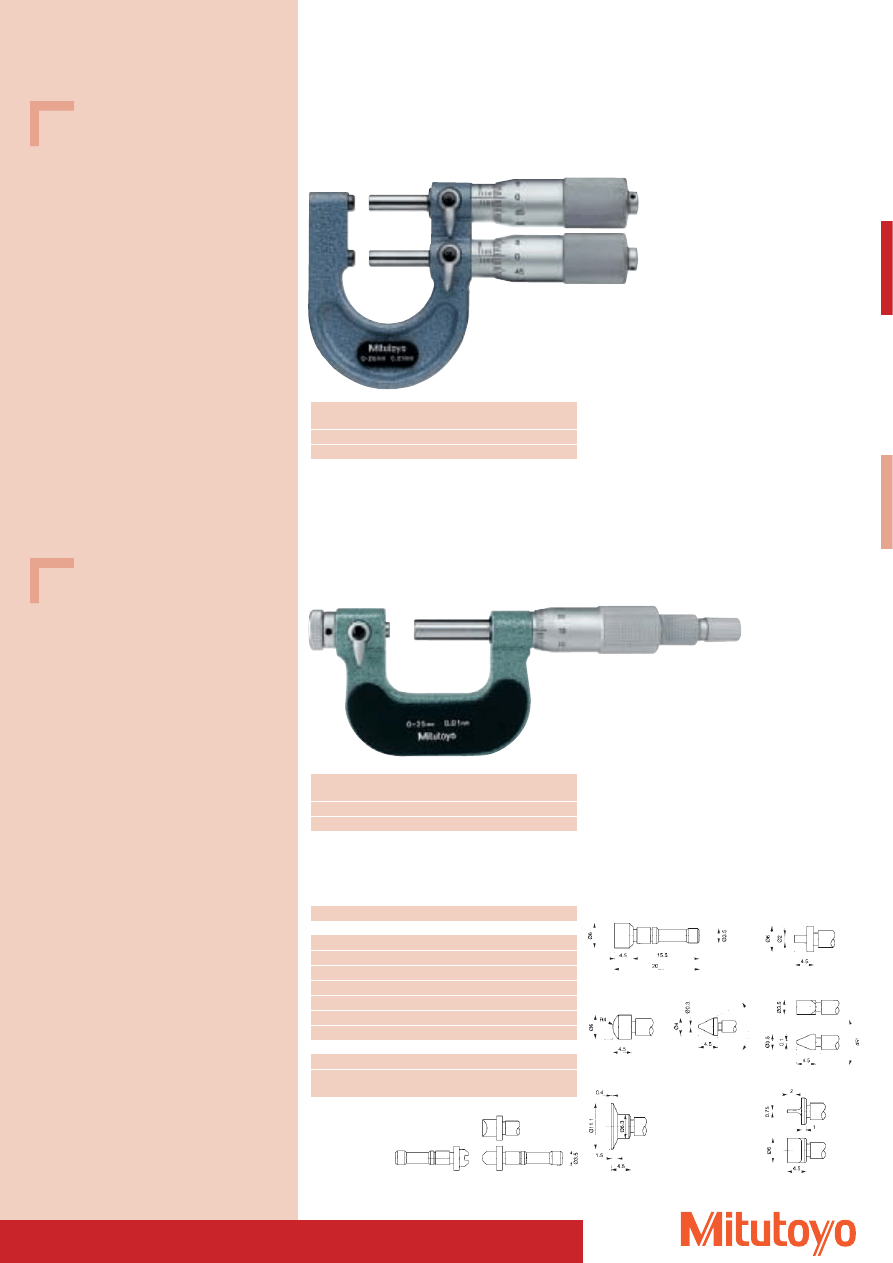
57
Series 113
for tolerance comparison
To be used as OK and reject evaluations
113–102
Limit Micrometer Special version
Limit Micrometer Special version
• With non-rotating spindle and exchangeable measuring inserts.
Measuring range
No.
Mass
mm
g
0–25
113–102
340
25–50
113–103
380
Series 116
DIN 863, Form D 16
116–101
116–801
Measuring range
No.
Mass
mm
g
0–25
116–101
250
25–50
116–102
300
No.
Comment
Individual measuring inserts
116–801
Measuring insert, flat type (pair)
116–802
Measuring insert with stepped measuring surfaces
116–803
Measuring insert, semis-circular type (pair)
116–804
Measuring insert, pointed type (pair)
116–805
Measuring insert, spline type (pair)
116–806
Measuring insert, disc-type (pair)
116–807
Measuring insert, knife-edge type (pair)
Measuring insert sets
116–800
7 Pairs of measuring inserts No. 116–801 to –807
116–830
6 Pairs of inserts for measuring threads
metric, pitch 0,4–7 mm
Series 116
Optional accessories (measuring inserts)
116–802
116–803
116–804
116–805
116–806
With holohedral measuring surfaces
116–807
116–830
Specifications
Accuracy:
Factory specification
Error limit: 3 mm
Graduation:
0,01 mm
Scales:
thimble and sleeve
satin chrome finish,
Ø 18 mm
Measuring spindle: Ø 6,35 mm
spindle pitch 0,5 mm,
with spindle lock
Measuring surfaces: carbide-tipped,
with clamping device
micro-lap finish
Frame:
enamelled
Including box, gauge block (from 25–50 mm), key
Specifications
Accuracy:
DIN 863-1
Graduation:
0,01 mm
Scales:
thimble and sleeve
satin chrome finish,
Ø 18 mm
Measuring spindle: Ø 8 mm
spindle pitch 0,5 mm,
with spindle lock
Frame:
enamelled
Measuring force: 5–10 N
Including box, gauge block (from 25–50 mm),
insulation, key
Measuring inserts not included
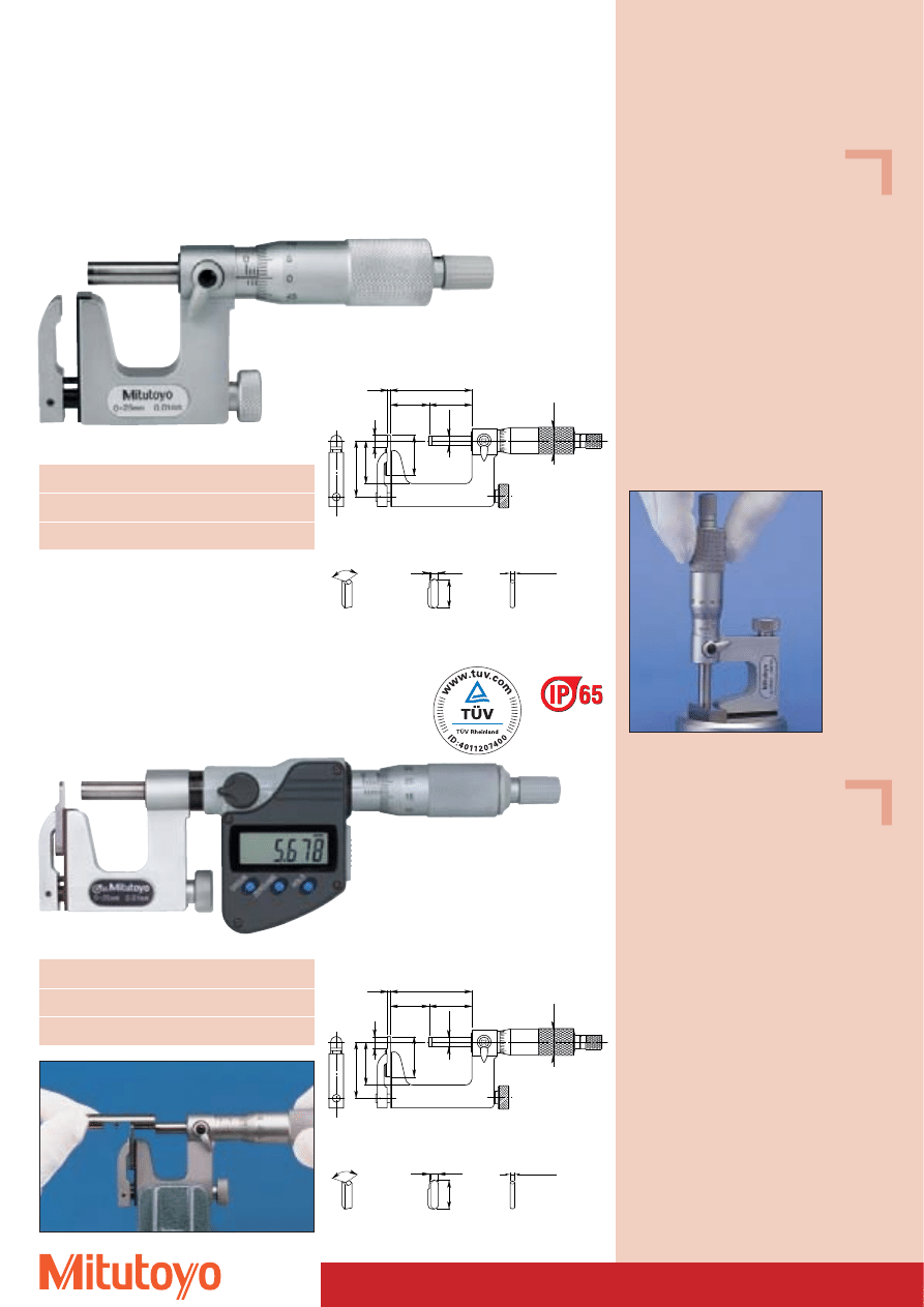
Micrometer Special version
• With replaceable anvil.
• For measuring wall thickness of cylinders and tubes as well as openings and slots
from edge to edge and hard-to-reach locations.
Series 117
Analogue version
Measuring range
No.
Composition
mm
0–25
117–101
Anvil No. 201217 Ø 3 mm
Anvil No. 201216 flat
25–50
117–102
Anvil No. 201379 Ø 5 mm
Anvil No. 201216 flat
117–101
Series 317
“DIGIMATIC” Type, with data output
1.5
52.5(27.5)
25(0)
27.5
1.5
34
26.5
7
25
ø6.35
120
6.35
25
Ø18
Dimension of 117–102 (117–101)
Measuring range
No.
Composition
mm
0–25
317–251
Anvil No. 201217 Ø 3 mm
Anvil No. 201216 flat
25–50
317–252
Anvil No. 201379 Ø 5 mm
Anvil No. 201216 flat
58
Specifications
Accuracy:
Factory specification
Error limit: 4 mm
Graduation:
0,01 mm
Scales:
thimble and sleeve
satin chrome finish
Measuring spindle: Ø 6,35 mm,
spindle pitch 0,5 mm
with spindle lock
Measuring surfaces: carbide-tipped
Frame:
steel, satin chrome finish
Measuring force:
5–10 N
Including box, gauge block (25–50 mm), key
Optional accessories
No. 201218
V-anvil
No. 950758
Round dial
Only for measuring range 0–25 mm
Specifications
Protection class:
IP-65
Accuracy:
Factory specification
Error limit: 4 mm
Resolution:
0,001 mm
Scales:
thimble and sleeve
satin chrome finish
Measuring spindle: Ø 6,35 mm,
spindle pitch 0,5 mm
with spindle lock
Measuring surfaces: carbide-tipped
Frame:
steel, satin chrome finish
Measuring force:
5–10 N
Including box, gauge block (25–50 mm),
key, 1 battery
Optional accessories
No. 201218
V-anvil
No. 950758
Round dial
Only for measuring range 0–25 mm
No. 05CZA662
Signal cable (1 m)
No. 05CZA663
Signal cable (2 m)
Consumable Spares
No. 938882
Battery SR-44
1.5
52.5(27.5)
25(0)
27.5
1.5
34
26.5
7
25
ø6.35
120
6.35
25
Ø18
Dimension of 317–252 (317–251)
120
1.5
6.35
25
Ø3
Ø5
Flat anvil
(standard accessory)
V-anvil
(optional accessory)
Round anvil
(standard accessory)
117–101 with 950758
317–251
120
1.5
6.35
25
Ø3
Ø5
Flat anvil
(standard accessory)
V-anvil
(optional accessory)
Round anvil
(standard accessory)
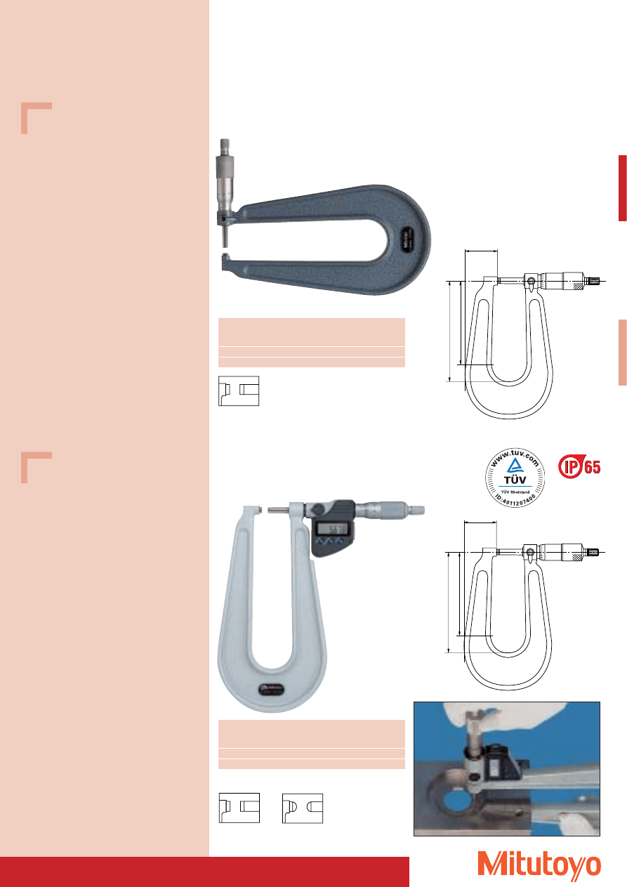
59
Specifications
Accuracy:
DIN 863-1
(throat depth 160 mm)
Factory specification
Error limit: 5 mm
(throat depth 330 mm)
Graduation:
0,01 mm
Scales:
thimble and sleeve
satin chrome finish,
Ø 18 mm bzw. Ø 21 mm
Measuring spindle: throat depth up to 150 mm:
Ø 6,35 mm
throat depth up to 300 mm:
Ø 8 mm
spindle pitch 0,5 mm,
with spindle lock
Measuring surfaces: carbide-tipped,
precision ground,
micro-lap finish
Frame:
enamelled
Measuring force:
5–10 N
Including box, key
Specifications
Protection class:
IP-65
Accuracy:
DIN 863-1
Resolution:
0,001 mm
Scales:
thimble and sleeve
satin chrome finish,
Ø 18 mm
Measuring spindle: Ø 6,35 mm,
spindle pitch 0,5 mm,
with spindle lock
Measuring surfaces: carbide-tipped,
precision ground,
micro-lap finish
Frame:
enamelled
Measuring force:
3–8 N
Including box, key, 1 battery
Optional accessories
No. 05CZA662
Signal cable (1 m)
No. 05CZA663
Signal cable (2 m)
Consumable Spares
No. 938882
Battery SR-44
Series 118
DIN 863, Form D 8
Measuring
No.
Throat depth
Mass
range
a
b
c
mm
mm
mm
mm
g
0–25
118–102
160
150
48
740
0–25
118–103
330
300
84
2650
118–102
Outside Micrometer Special version
• With deep throat.
• For measuring semi-finished products with a large surface area.
Series 389
“DIGIMATIC” Type, with data output
DIN 863, Form D 8
Measuring
No.
Throat depth
Mass
range
a
b
c
mm
mm
mm
mm
g
0–25
389–251
160
150
48
840
0–25
389–271*
160
150
48
840
389–251
* (with spherical measuring surfaces)
389–271
389–251
118–102 / 118–103
c
a
b
c
a
b
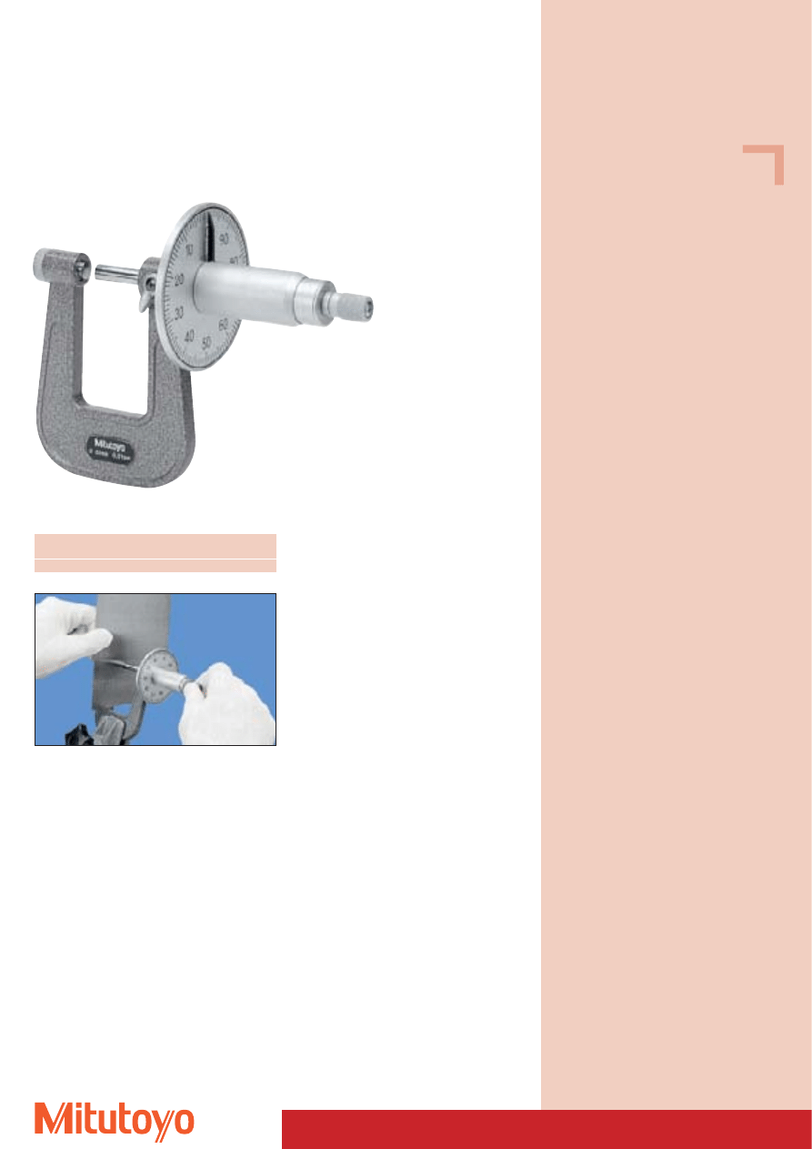
60
Micrometer Special version
• For measuring sheet and strip metal.
Series 119
DIN 863, Form D 9
Measuring range
No.
Throat depth
Mass
mm
mm
g
0–25
119–202
50
305
119–202
Specifications
Accuracy:
DIN 863-1
Graduation:
0,01 mm
Scales:
thimble and sleeve
satin chrome finish,
Measuring spindle: Ø 6,35 mm,
with spindle lock
Measuring surfaces: Convex anvil and level spindle
Frame:
enamelled
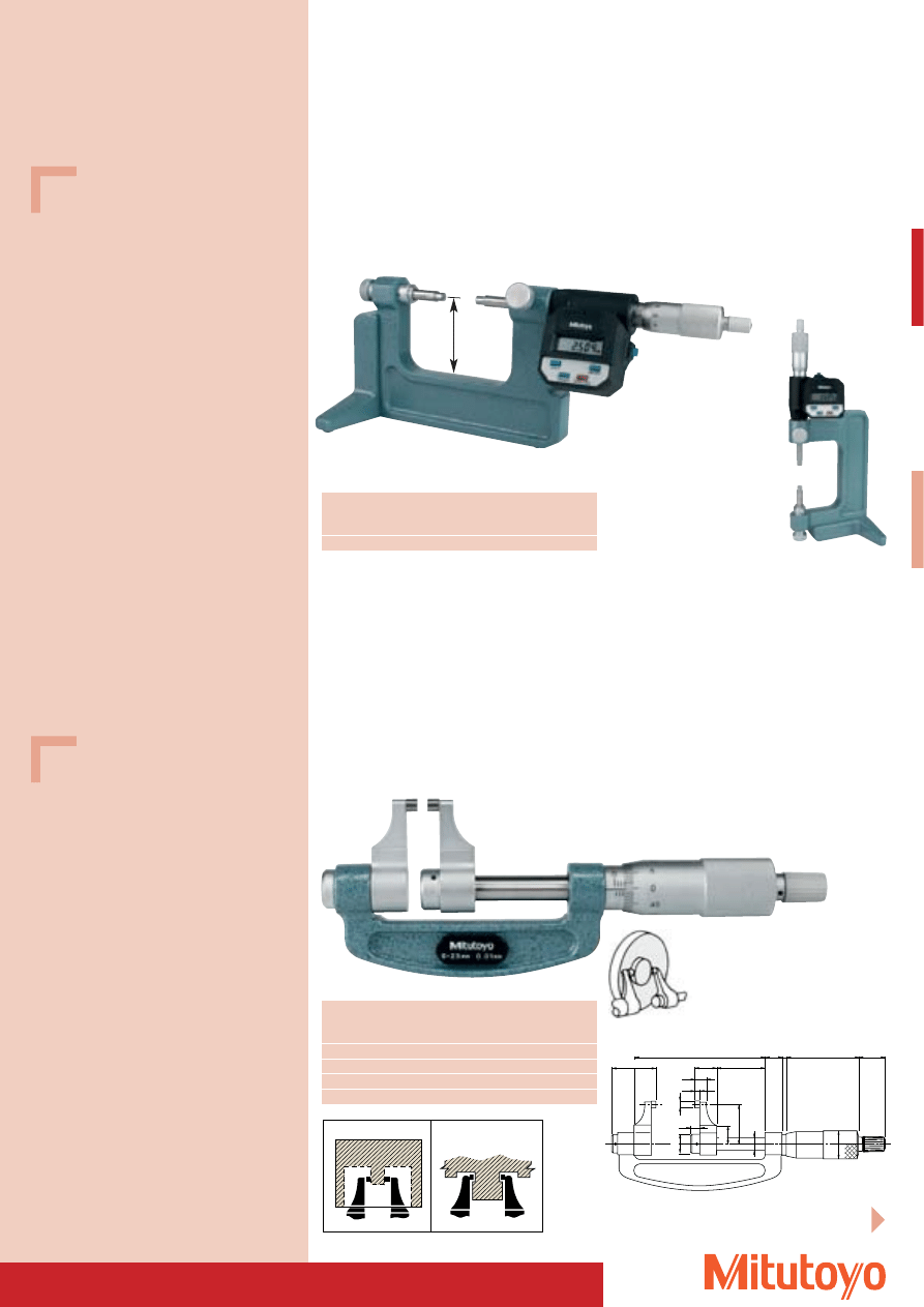
61
Outside Micrometer Special version
• Bench Micrometer.
• Rugged, stable cast iron base for vertical and horizontal placing.
• The display with operation keys can be turned for optimum reading.
Series 121
“DIGIMATIC” Type, with data output
DIN 863, Form D 19
Measuring Opening
No.
Mass
range
mm
mm
g
0–50
25
121–145
2300
121–145
Outside Micrometer Special version
• With measuring jaws.
• This type of micrometer has been especially designed for measuring hard-to-reach places.
Series 143
Analogue version
Measuring
No.
L
a
b
c
Mass
range
mm
mm
mm
mm
mm
g
0– 25
143–101
59,8
31,8
10,6
28,6
210
25– 50
143–102
84,8
31,8
10,6
28,6
230
50– 75
143–103
109,8
31,8
10,6
28,6
280
75–100
143–104
134,8
31,8
10,6
28,6
330
143–101
L
7.4
14
a
3.4
Ø 4
Ø 13
12.5
25.7
5.9
C
3
47
17
b
Ø 8
Ø 18
For the “DIGIMATIC” Type,
refer next pages
Specifications
Accuracy:
Factory specification
Error limit: 2 mm
Resolution:
0,001 mm
Scales:
thimble and sleeve
satin chrome finish,
Ø 18 mm
Measuring spindle: Ø 6,35 mm,
spindle pitch 0,5 mm
Measuring force:
5–10 N
Including 2 interchangeable anvils for measuring
ranges 0–25 mm and 25–50 mm, gauge block,
2 batteries
Optional accessories
No. 937387
Signal cable (1 m)
No. 965013
Signal cable (2 m)
Consumable Spares
No. 938882
Battery SR-44
Specifications
Accuracy:
Factory specification
Error limit:
0– 25 mm: 5 mm;
25– 50 mm: 6 mm;
50– 75 mm: 7 mm;
75–100 mm: 8 mm
Graduation:
0,01 mm
Scales:
thimble and sleeve
satin chrome finish,
Ø 18 mm
Measuring spindle: Ø 6,35 mm,
spindle pitch 0,5 mm
Measuring surfaces: carbide-tipped,
precision ground,
micro-lap finish
Frame:
enamelled
Including box, gauge block (from 25–50 mm),
key
60 mm
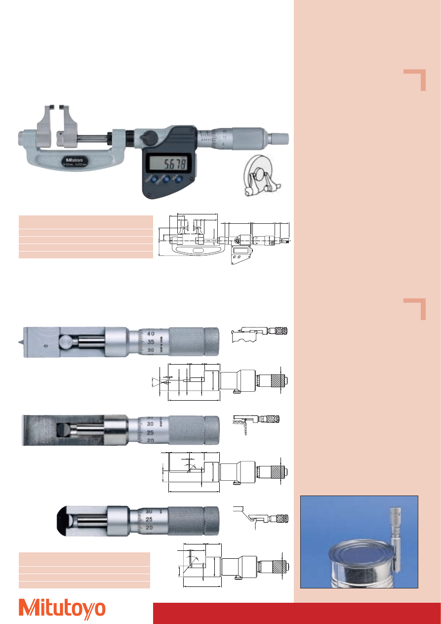
62
Specifications
Accuracy:
Factory specification
Error limit:
0– 25 mm: 5 mm;
25– 50 mm: 6 mm;
50– 75 mm: 7 mm;
75–100 mm: 8 mm
Resolution:
0,001 mm
Scales:
thimble and sleeve
satin chrome finish, Ø 18 mm
Measuring spindle: Ø 6,35 mm,
spindle pitch 0,5 mm
Measuring surfaces: carbide-tipped,
precision ground,
micro-lap finish
Frame:
enamelled
Including box, gauge block (from 25–50 mm),
key, 1 battery
Optional accessories
No. 05CZA662
Signal cable (1 m)
No. 05CZA663
Signal cable (2 m)
Consumable Spares
No. 938882
Battery SR-44
Specifications
Accuracy: Factory specification
Error limit: 3 mm
Graduation: 0,01 mm
Scales:
thimble and sleeve
satin chrome finish
Including box, key
343–250
Outside Micrometer Special version
• With measuring jaws.
• This type of micrometer has been especially designed for measuring hard-to-reach places.
Measuring range
No.
L
a
Mass
mm
mm
mm
g
0– 25
343–250
59,8
27,5
320
25– 50
343–251
84,8
30,0
340
50– 75
343–252
109,8
32,5
390
75–100
343–253
134,8
35,0
440
Series 343
“DIGIMATIC” Type, with data output
11.25
Ø15
40
°
10.65
11.25
9.25
Ø20
15
22
16
53
2
11.25
Ø15
9.25
Ø20
22.5
15
1.5
16
38.5
40
°
Series 147
• For accurate control of depth and thickness of seams on cans.
Can seem measurement
(depth up to 5 mm)
147–105
for aluminium cans
147–202
for sprayer cans
Measuring range
No.
Mass
mm
g
0–13
147–103
65
0–13
147–105
65
0–13
147–202
65
10.15
1.3
Ø15
9.3
Ø20
15
0.5
20
45
°
16
52.5
1.5
147–103
Can Seam Micrometer Special version
3.4
Ø 4
Ø 4
3.4
7.4
7.4
12
.5
25
.7
Ø 6
.35
11.3
47.2
2.3 3
41
11.5
17
Ø 1
8
L
31.8
28.6
a
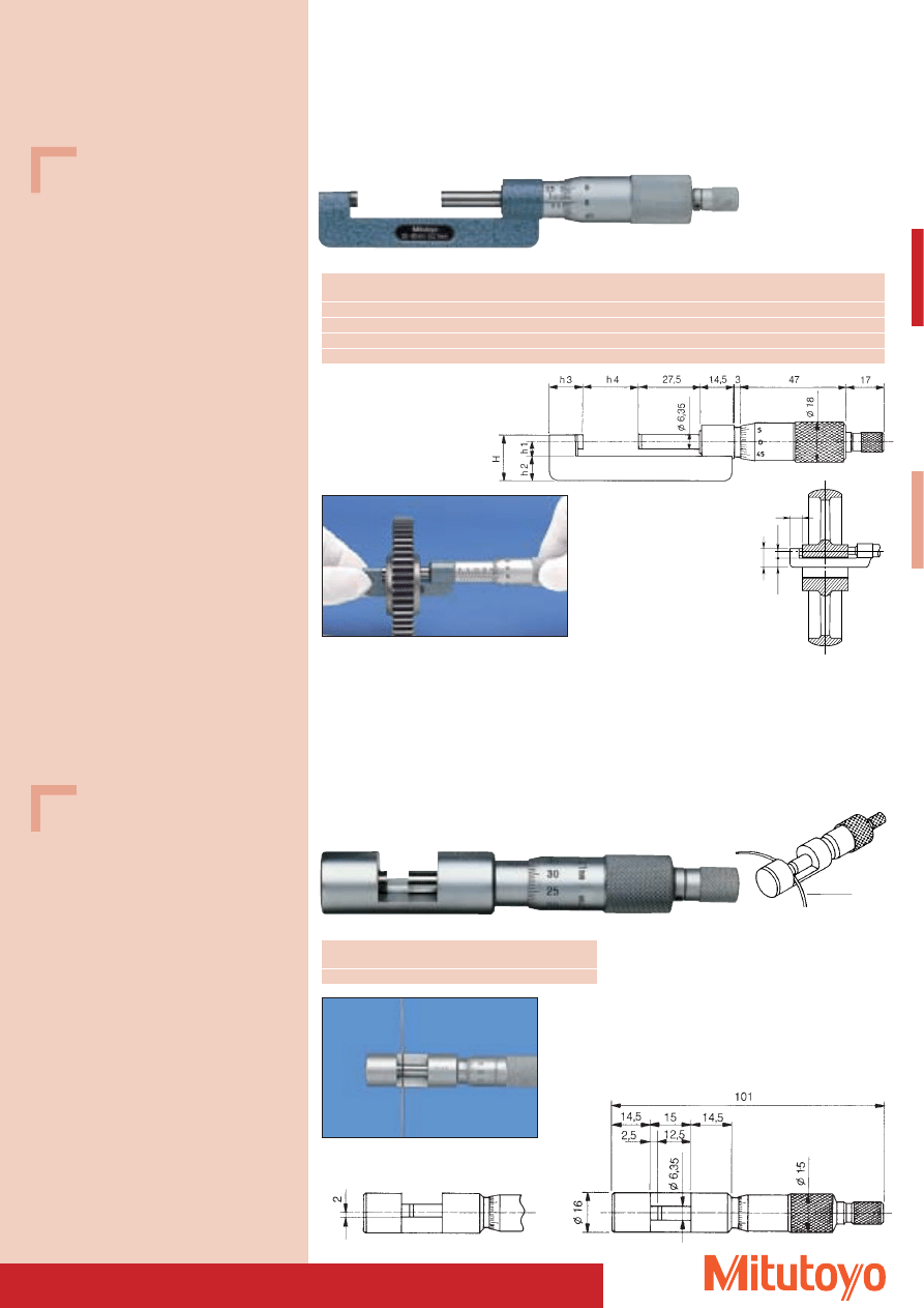
63
Hub Micrometer Special version
• With extra flat throat.
• For measuring bearing bushings etc.
Wire Micrometer Special version
• With little throat.
• For measuring wire and ball.
Measuring range
No.
H
h1
h2
h3
h4
Mass
mm
mm
mm
mm
mm
mm
g
0– 25
147–301
17,5
6,0
8,5
13,5
0
135
25– 50
147–302
20,5
6,5
11,0
14,0
25
150
50– 75
147–303
20,5
6,5
11,0
13,0
50
170
75–100
147–304
20,5
6,5
11,0
13,0
75
185
Sample application
Wire
Measuring range
No.
Mass
mm
g
0–10
147–401
65
Series 147
DIN 863, Form D 2
h3
h1
h2
H
Specifications
Accuracy:
DIN 863-1
Graduation:
0,01 mm
Scales:
thimble and sleeve
satin chrome finish
Measuring spindle: spindle pitch 0,5 mm
Measuring surfaces: carbide-tipped,
precision ground,
micro-lap finish
Measuring force:
5–10 N
Including box, key
Specifications
Accuracy:
Factory specification
Error limit:
0– 25 mm: 2 mm;
25– 50 mm: 2 mm;
50– 75 mm: 2 mm;
75–100 mm: 3 mm
Graduation:
0,01 mm
Scales:
thimble and sleeve
satin chrome finish
Measuring spindle: spindle pitch 0,5 mm
Measuring surfaces: carbide-tipped,
precision ground,
micro-lap finish
Frame:
enamelled
Measuring force:
5–10 N
Including box, gauge block (from 25–50 mm),
key
Series 147
147–302
147–401
Sample application
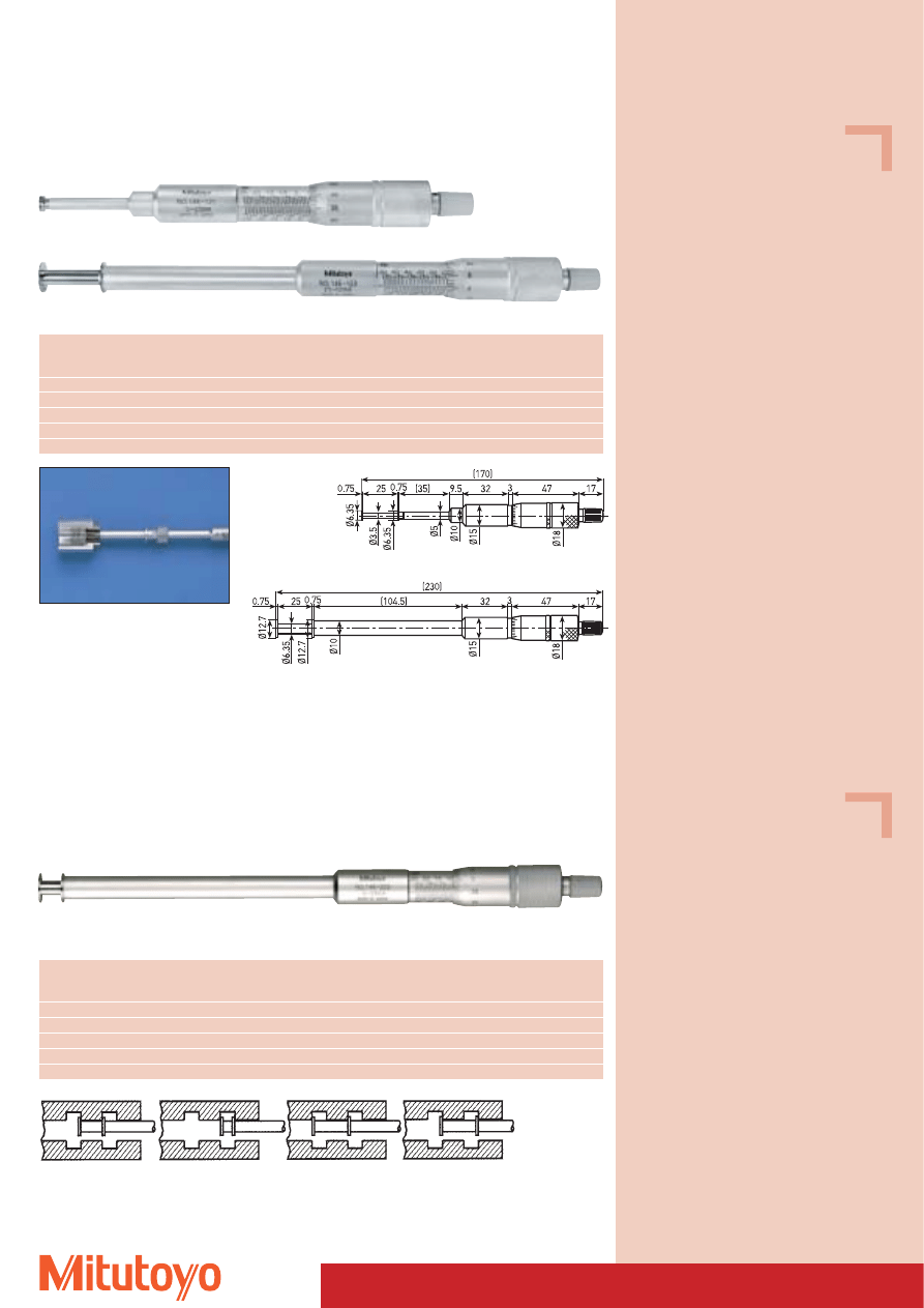
64
Specifications
Accuracy:
Factory specification
Error limit: 10 mm
Graduation:
0,01 mm
Scales:
thimble and sleeve
satin chrome finish,
Ø 18 mm
Measuring spindle: spindle pitch 0,5 mm
Measuring surfaces: hardened
Ratchet:
Can be used in both
directions
Including box, key
Specifications
Accuracy:
Factory specification
Error limit: 10 mm
Graduation:
0,01 mm
Parallelism:
10 mm
Scales:
thimble and sleeve
satin chrome finish,
Ø 18 mm
Measuring spindle: spindle pitch 0,5 mm
Measuring surfaces: hardened
Ratchet:
Can be used in both
directions
Measuring force:
5–10 N
Including box, key
Internal Groove Micrometer
• For measuring internal cross grooves, steps in bores etc.
146–222
No.
Measuring range
Measuring range
Diameter of
Thickness of
Mass
external
internal
measuring plate
measuring plate
mm
mm
mm
mm
g
146–221
0– 25
1,6– 26,5
6,35
0,75
135
146–222
0– 25
1,6– 26,5
12,70
0,75
185
146–223
25– 50
26,5– 51,5
12,70
0,75
175
146–224
50– 75
51,5– 76,5
12,70
0,75
165
146–225
75–100
76,5–101,5
12,70
0,75
160
Series 146
With non-rotating spindle
Internal Groove Micrometer
• For measuring internal cross grooves, steps in bores etc.
146–123
146–121
146–122
Measuring range
Measuring range
No.
Diameter of
Thickness of
Mass
external
internal
measuring plate
measuring plate
mm
mm
mm
mm
g
0– 25
1,6– 26,5
146–121
6,35
0,75
135
0– 25
1,6– 26,5
146–122
12,70
0,75
185
25– 50
26,5– 51,5
146–123
12,70
0,75
175
50– 75
51,5– 76,5
146–124
12,70
0,75
165
75–100
76,5–101,5
146–125
12,70
0,75
160
146–121
Series 146
With rotating spindle
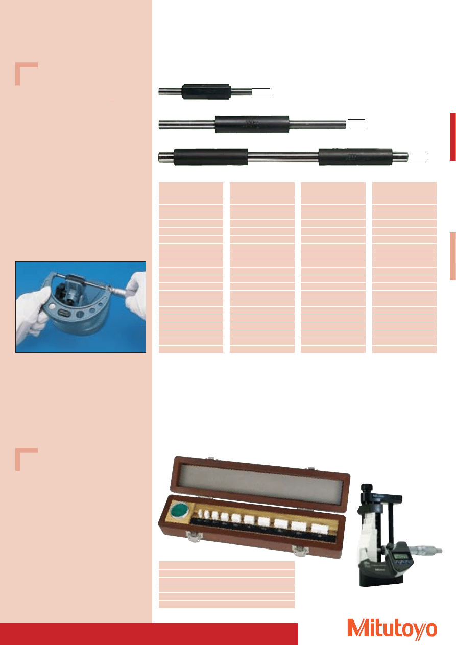
65
Standards for Outside Micrometers
• Control and adjustment of all outside micrometers with a minimum of 25 mm measuring range.
Test set for outside micrometers
• Micrometer test sets for testing the deviation of outside micrometers in accordance with DIN 863.
• Micrometers with a measuring range in excess of 25 mm are tested by adding a gauge block
of 25, 50 or 75 mm to these tests.
Sets
No. 167–902
Nominal value 25–125 mm
No. 167–903
Nominal value 25–275 mm
Nominal d
No.
value mm mm
25
6,35
167–101
50
6,35
167–102
75
6,35
167–103
100
7,9
167–104
125
7,9
167–105
150
7,9
167–106
175
7,9
167–107
200
9,4
167–108
225
9,4
167–109
250
9,4
167–110
275
9,4
167–111
300
9,4
167–112
325
9,4
167–113
350
9,4
167–114
375
9,4
167–115
400
9,4
167–116
425
9,4
167–117
450
9,4
167–118
475
9,4
167–119
500
11,9
167–120
Nominal d
No.
value mm mm
525
11,9
167–121
550
11,9
167–122
575
11,9
167–123
600
11,9
167–124
625
11,9
167–125
650
11,9
167–126
675
11,9
167–127
700
11,9
167–128
725
11,9
167–129
750
11,9
167–130
775
11,9
167–131
800
11,9
167–132
825
11,9
167–133
850
11,9
167–134
875
11,9
167–135
900
11,9
167–136
925
11,9
167–137
950
11,9
167–138
975
11,9
167–139
1000
11,9
167–140
Nominal d
No.
value mm mm
1025
11,9
167–365
1050
11,9
167–366
1075
11,9
167–367
1100
11,9
167–368
1125
11,9
167–369
1150
11,9
167–370
1175
11,9
167–371
1200
11,9
167–372
1225
11,9
167–373
1250
11,9
167–374
1275
11,9
167–375
1300
11,9
167–376
1325
11,9
167–377
1350
11,9
167–378
1375
11,9
167–379
1400
11,9
167–380
1425
11,9
167–381
1450
11,9
167–382
1475
11,9
167–383
1500
11,9
167–384
Nominal d
No.
value mm mm
1525
11,9
167–385
1550
11,9
167–386
1575
11,9
167–387
1600
11,9
167–388
1625
11,9
167–389
1650
11,9
167–390
1675
11,9
167–391
1700
11,9
167–392
1725
11,9
167–393
1750
11,9
167–394
1775
11,9
167–395
1800
11,9
167–396
1825
11,9
167–397
1850
11,9
167–398
1875
11,9
167–399
1900
11,9
167–400
1925
11,9
167–401
1950
11,9
167–402
1975
11,9
167–403
2000
11,9
167–404
Series 167
167–103
167–106
167–108
Additinal accessories for micrometers
see pages 66–69
d
d
d
516–156–10
516–607
Specifications
Accuracy:
Factory specification
Error limit: (1 +
L
50
) mm;
L in mm
Measuring surfaces: micro-lap finish
Flatness:
0,3 mm
Parallelism:
2 mm
With indication of true value
Including insulation
Specifications
Dimension :
2,5
5,1
7,7 10,3 12,9
15,0 17,6 20,2 22,8 25,0
Number per set: 10
Including 1 optical glass parallel 12 mm thick,
diameter 30 mm
Optional accessories
No. 516–607
Gauge block holder for testing
external screw type micrometers
Series 516
No.
Degree of accuracy
Material
516–156–10
0
Ceramic
516–157–10
1
Ceramic
516–106–10
0
Steel
516–107–10
1
Steel
516–108–10
2
Steel
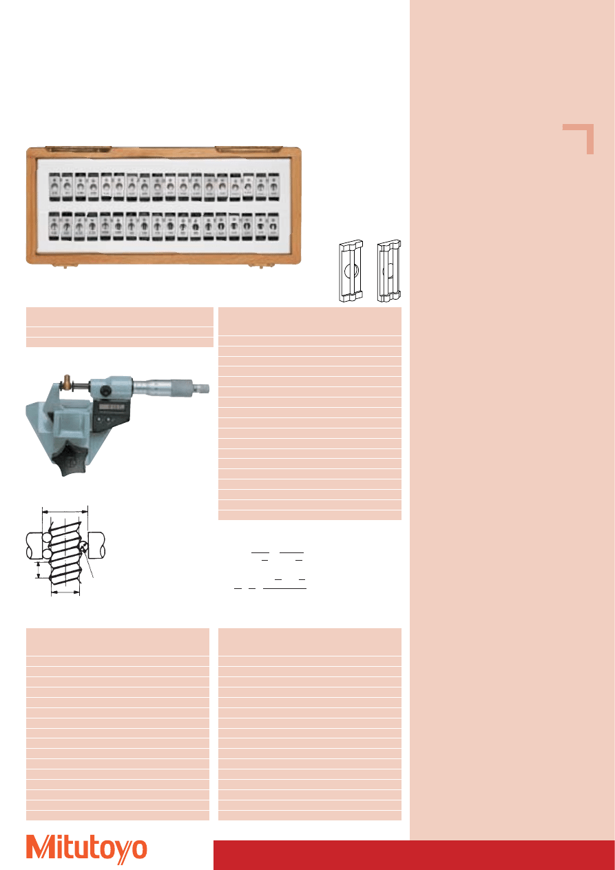
66
Specifications
Tolerance of
measuring wires: ± 1 mm
Contents:
18 pairs of tips
Ø 0,170 mm
up to Ø 3,200 mm
Including wooden box
3-Wire Unit
• The measuring wires are hardened and precision lapped. They are placed onto spindle and anvil
of the outside micrometer.
• The three-wire measuring process is applied to determine the pitch diameter of threads and
considered as one of the most accurate measuring procedures.
313–101
No.
Supporter diameter
Contents
mm
313–101
6,35
18 pairs of tips (see right)
313–102
8,00
18 pairs of tips (see right)
Contents No. 313–101 Contents No. 313–102 Measuring
(Ø 6,35 mm)
(Ø 8,00 mm)
wire Ø
No.
No.
mm
952131
952149
0,170
952132
952150
0,195
952133
952151
0,220
952134
952152
0,250
952135
952153
0,290
952136
952154
0,335
952137
952155
0,390
952138
952156
0,455
952139
952157
0,530
952140
952158
0,620
952141
952159
0,725
952142
952160
0,895
952143
952161
1,100
952144
952162
1,350
952145
952163
1,650
952146
952164
2,050
952147
952165
2,550
952148
952166
3,200
Nominal
Thread
Pitch
Measuring
Outside dim.
pitch
Ø
wire Ø
P
d
2
d
D
M
M–d
2
M 1
0,25
0,838
0,170
1,133
0,295
M 1,2
0,25
1,038
0,170
1,332
0,294
M 1,4
0,30
1,205
0,170
1,456
0,251
M 1,7
0,35
1,473
0,220
1,831
0,358
M 2
0,40
1,740
0,250
2,145
0,405
M 2,3
0,40
2,040
0,250
2,444
0,404
M 2,6
0,45
2,308
0,290
2,789
0,481
M 3
0,50
2,675
0,290
3,113
0,438
M 3,5
0,60
3,110
0,335
3,596
0,486
M 4
0,70
3,545
0,455
4,305
0,760
M 5
0,80
4,480
0,455
5,153
0,673
M 6
1,00
5,350
0,620
6,346
0,996
M 8
1,25
7,188
0,725
8,282
1,094
M 10
1,50
9,026
0,895
10,414
1,388
M 12
1,75
10,863
1,100
12,650
1,787
M 14
2,00
12,701
1,350
15,021
2,320
Nominal
Thread
Pitch
Measuring
Outside dim.
pitch
Ø
wire Ø
P
d
2
d
D
M
M–d
2
M 16
2,00
14,701
1,350
17,021
2,320
M 20
2,50
18,376
1,650
21,163
2,787
M 22
2,50
20,376
1,650
23,163
2,787
M 24
3,00
22,051
2,050
25,606
3,555
M 27
3,00
25,051
2,050
28,605
3,554
M 30
3,50
27,727
2,050
30,848
3,121
M 33
3,50
30,727
2,050
33,848
3,121
M 36
4,00
33,402
2,550
37,591
4,189
M 39
4,00
36,402
2,550
40,590
4,188
M 42
4,50
39,077
2,550
42,832
3,755
M 45
4,50
42,077
2,550
45,832
3,755
M 48
5,00
44,752
3,200
50,025
5,273
M 52
5,00
48,752
3,200
54,024
5,272
M 56
5,50
52,428
3,200
57,267
4,839
M 60
5,50
56,428
3,200
61,267
4,839
Series 313
Thread measuring wires (pair)
3-Wire Unit Sets
Metric Threads DIN 13 Page 1
M = d
2
+ – + d
D
+ d
d
D
sin a
2
P
2tan a
2
d =
·
·
P
2
p
2
d
D
2
cos · cot
d
2
2
a
2
a
2
P = thread pitch
d
D
= measuring wire Ø
d
2
= pitch diameter
M = theoretical dimension at
measuring pressure d
a = pitch angle
d = Correction factor
M
P
d
d
2
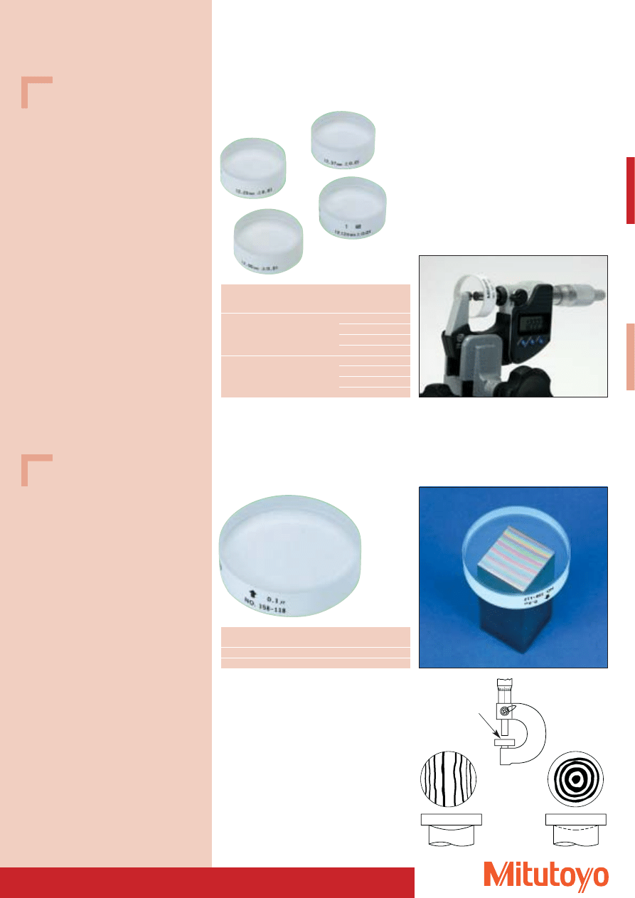
67
Optical Parallel
157–101
Series 157
• For testing surface flatness and parallelism of measuring surfaces of outside micrometers.
Optical Glas flat
158–118
Series 158
• For testing surface flatness.
No.
Nominal
Diameter
mm
mm
158–118
12
45
158–120
15
60
Viewing direction
Curved
measuring surface
Concave
measuring surface
Glass flat
Glass flat
Measuring anvil
Measuring anvil
Specifications
Flatness:
0,1 mm
Parallelism: 0,2 mm
Diameter: 30 mm
Specifications
Flatness: 0,1 mm
Range of
No.
Contents
Nominal
outside micrometer
mm
mm
0–25
157–903
157–101
12,00
157–102
12,12
157–103
12,25
157–104
12,37
25–50
157–904
157–105
25,00
157–106
25,12
157–107
25,25
157–108
25,37

68
Micrometer Stand for Outside Micrometers
• Keeps both hands free for operating the micrometer and positioning the workpieces.
• Designed for serial measurements in manufacturing and quality assurance.
Series 156
For holding outside micrometers up to 50 mm measuring range.
With fixed 45° inclination
156–105 M
97
Max. 63
35
2.5
4 - 12
Micrometer Stand for Outside Micrometers
• Keeps both hands free for operating the micrometer and positioning the workpieces.
• Designed for serial measurements in manufacturing and quality assurance.
156–101 M
97
Max. 63
0 - 18
30
55.8
102.15
31.5
139.5
Series 156
For holding outside micrometers up to 100 mm measuring range.
Cast iron construction with adjustable angles
Specifications
No. 156–105 M
Mass: 700 g
Specifications
No. 156–101 M
Mass: 1100 g
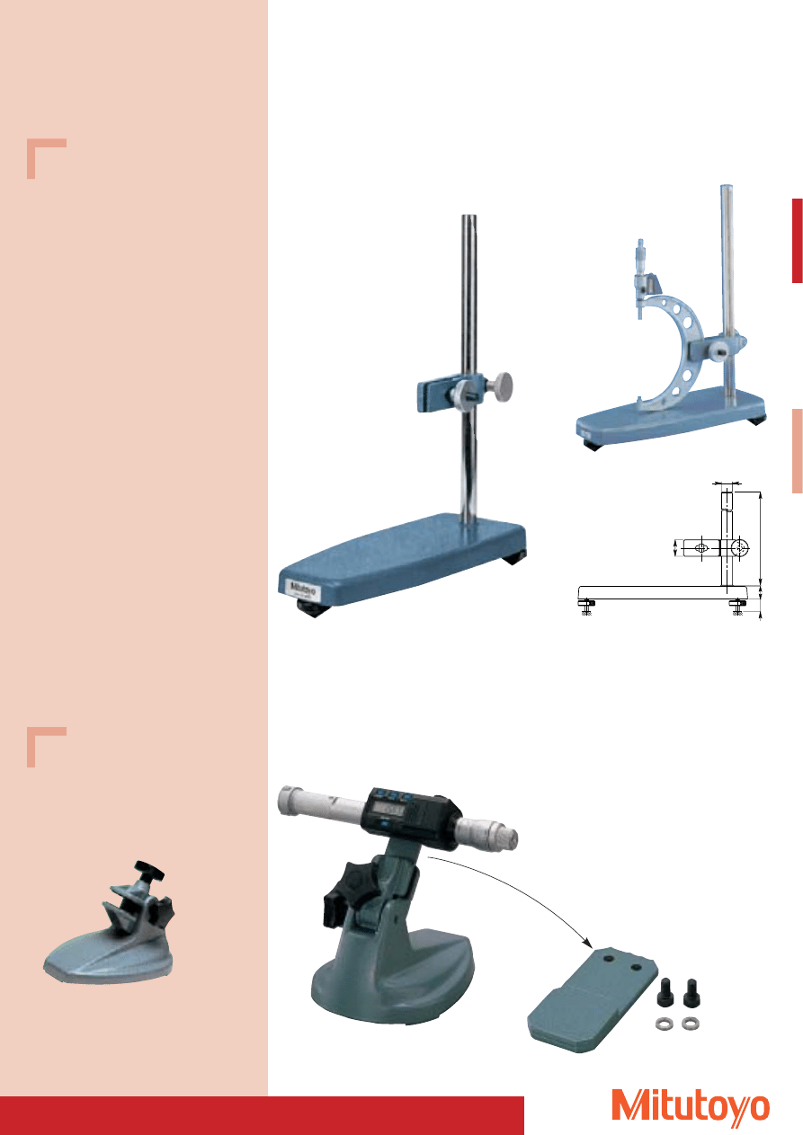
69
Holder for “DIGIMATIC”-Holtest
Three-Point Internal Micrometer
• Designed for serial measurements in manufacturing and on the measuring stand.
982693
156–102
Micrometer Stand for Outside Micrometers
• Keeps both hands free for operating the micrometer and positioning the workpieces.
• Designed for serial measurements in manufacturing and quality assurance.
Series 156
For holding outside micrometers
from 100 mm through 300 mm measuring range.
Specifications
No. 156–102
Adjustable range
of the clamping system: approx. 400 mm
982693 +
156–101 M
(optional accessories)
Specifications
No. 982693
Holder for Holtest Three-Point
Internal Micrometer
Optional accessories
No. 156–101 M
Recommended base
Ø24.8
435
40
30
30
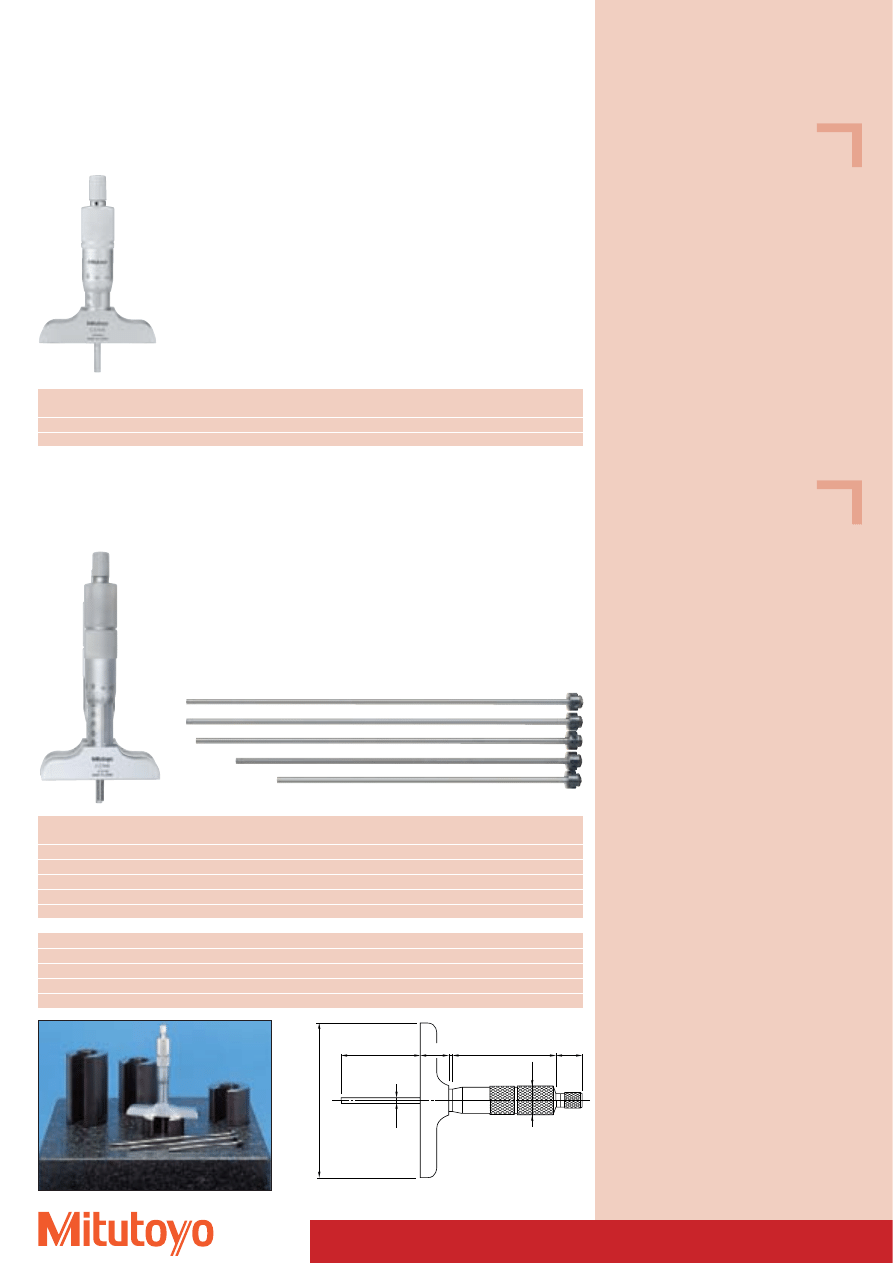
Ø18.3
65.4
17
3
18
50
Ø4
101.6
70
Depth Micrometer
Series 128
Fixed version without exchangeable measuring inserts
128–101
Measuring range
No.
Base
Error limits
mm
mm
Micrometers
0–25
128–101
60 x 16
3 mm
0–25
128–102
100 x 16
3 mm
Series 129
Version with exchangeable measuring inserts
Rods hardened
129–112
Measuring range
No.
Base
Number
Error limits
mm
mm
of rods
Micrometers
0– 50
129–109
60 x 16
2
3 mm
0– 75
129–110
60 x 16
3
3 mm
0–100
129–111
60 x 16
4
3 mm
0–150
129–112
60 x 16
6
3 mm
0–300
129–152
60 x 16
12
3 mm
0– 50
129–113
100 x 16
2
3 mm
0– 75
129–114
100 x 16
3
3 mm
0–100
129–115
100 x 16
4
3 mm
0–150
129–116
100 x 16
6
3 mm
0–300
129–153
100 x 16
12
3 mm
Specifications
Accuracy:
DIN 863-2
Graduation:
0,01 mm
Scales:
thimble and sleeve
satin chrome finish,
Ø 18 mm
Measuring span:
25 mm
Rod:
Ø 4 mm
spindle pitch:
0,5 mm,
with spindle lock
Measuring surfaces: hardened, precision ground,
micro-lap finish
Base:
hardened tool steel
Flatness:
60 mm: 1,3 mm
100 mm: 2 mm
Measuring force:
5–10 N
Including box, key
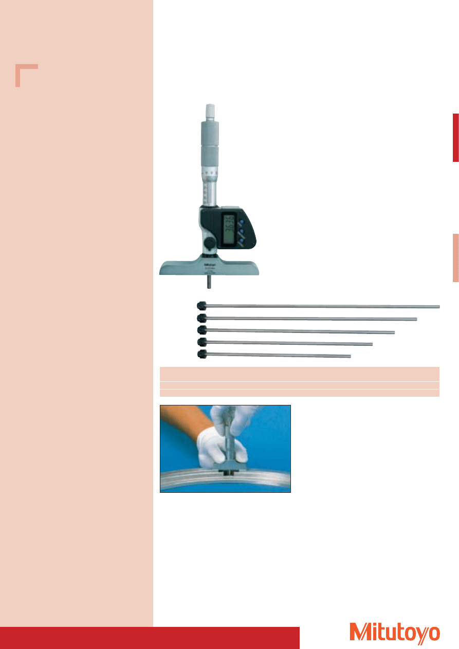
71
Specifications
Accuracy:
Factory specification
Resolution:
0,001 mm
Scales:
thimble and sleeve
satin chrome finish,
Ø 18 mm
Measuring span:
25 mm
Rod:
Ø 4 mm
spindle pitch:
0,5 mm,
with spindle lock
Measuring surfaces: hardened, precision ground,
micro-lap finish
Base:
hardened tool steel
Flatness Base:
2 mm
Tolerance of
interchangeable
measuring inserts:
± (2 + L/75) mm
L = measuring length in mm
Error limit with
“zero” measuring
insert:
5 mm
Measuring force:
5–10 N
Including box, key, battery
Optional accessories
No. 05CZA662
Signal cable (1 m)
No. 05CZA663
Signal cable (2 m)
Consumable Spares
No. 938882
Battery SR-44
Series 329
“DIGIMATIC” version with data output
and exchangeable measuring inserts
329–250
Depth Micrometer
Measuring range
No.
Base
Number Error
limits
mm
mm
of rods
Micrometers
0–150
329–250
100 x 16
6
3 mm
0–300
329–251
100 x 16
12
3 mm
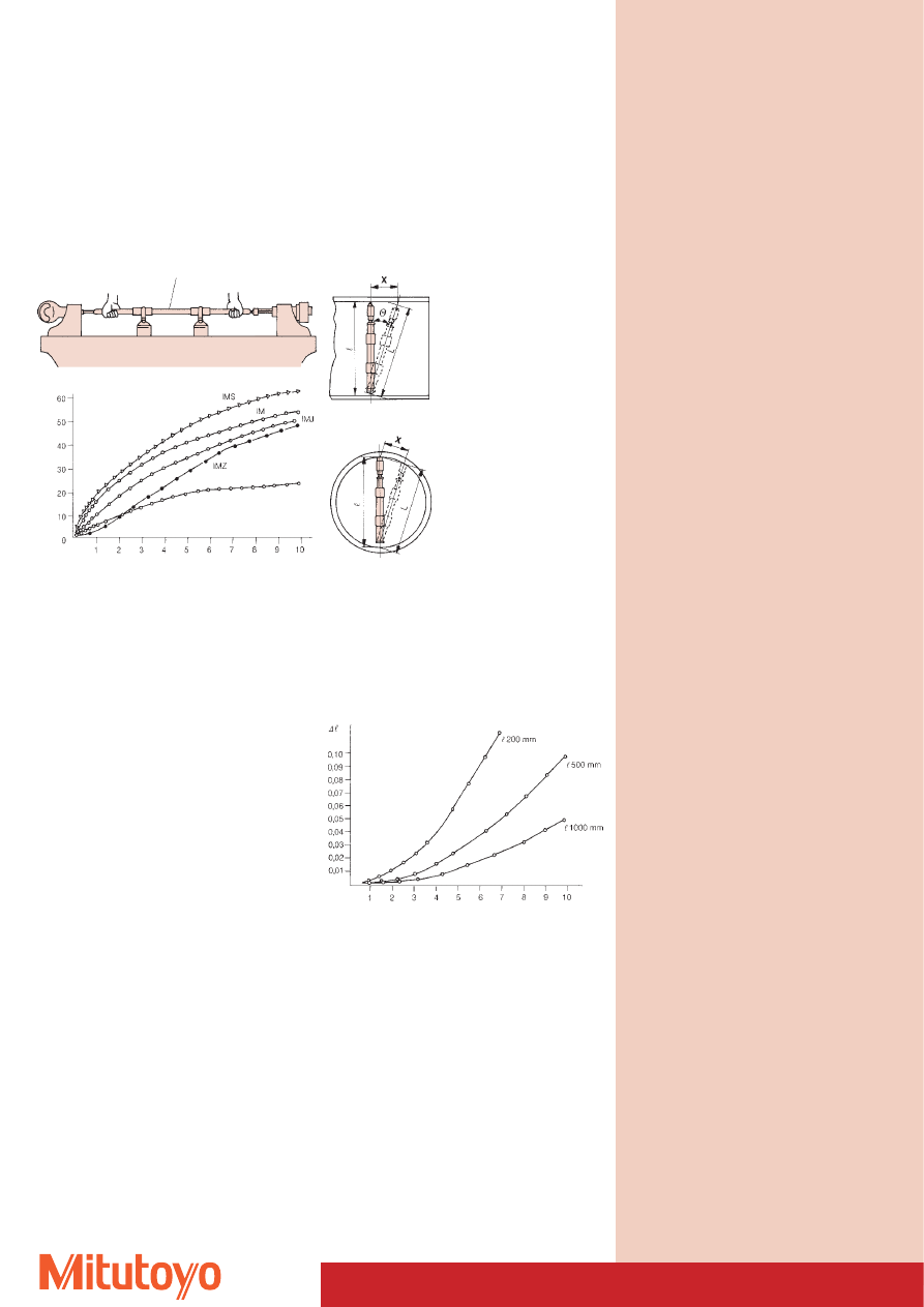
72
Basic Information
Inside Micrometers
Thermal expansion of inside micrometers due to heat
from hand
(models with measuring range of 1000 mm or more)
Inside Micrometer
Expansion (
m
m)
Time (Minutes)
(Insulation of IM)
Fig. 1
Length Measuring Machine
IMS:
Interchangeable rod type inside micrometer
(Series 141)
IM:
Single rod type inside micrometer
(Series 133)
IMJ:
Extension tube type inside micrometer
(Series 139, 140, 339)
IMZ:
Extension rod type inside micrometer
(Series 137, 337)
In case the micrometer is inclined in the direction of the
tube axis (see fig. 1), positive errors will result, as shown
in the graph below.
In case the micrometer is tilted sideways (in the lateral
direction) as shown in fig. 2 the results will be negative,
as approximated by the graph below.
Measurement errors due to incorrect positioning
(inclination) of inside micrometers
Fig. 2
Inclination (mm)
: Inside diameter of the tube
L: Measured length
X: Inclination
Measurement error, D , given
D = L – =
2
+ x
2
–
2
l
l
l
l
öäää
l
l
: Inside diameter of the tube
L: Measured length
X: Inclination
Measurement error, D , given
as follows:
D = L – =
2
– x
2
–
l
l
l
l
öäää
l
l
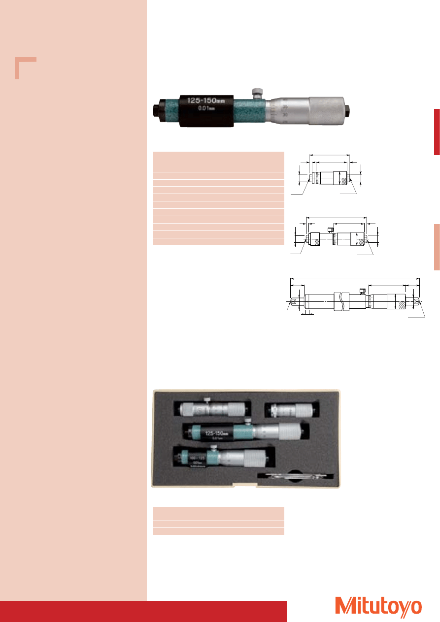
73
133–144
Tubular Inside Micrometer
• Light-weight design due to tubular construction.
133–146
Measuring
No.
L
a
b
Mass
range
mm
mm
mm
mm
g
50– 75
133–143
50
3,5
3
50
75–100
133–144
75
3,5
3
75
100–125
133–145
100
14,0
13
130
125–150
133–146
125
14,0
13
160
150–175
133–147
150
14,0
13
170
175–200
133–148
175
14,0
13
180
200–225
133–149
200
16,5
13
200
225–250
133–150
225
16,5
13
210
250–275
133–151
250
16,5
13
235
275–300
133–152
275
16,5
13
245
Series 133
Fixed construction
133–145 Z 133–152
L
37
Ø8
a
b
SR10
SR10
Ø8
Ø15
37
L
b
a
SR10
SR10
Ø8
Ø8
Ø15
Ø8
Ø8
L
a
47
b
Ø18
SR10
SR10
4
133–143
Measuring range
No.
Contents
mm
Set
50–150
133–901
4 micrometers
50–300
133–902
10 micrometers
Series 133
As a set
133–901
Specifications
Accuracy:
DIN 863/4
Graduation:
0,01 mm
Scales:
thimble and sleeve
satin chrome finish,
Ø 18 mm
Measuring spindle: spindle pitch 0,5 mm
with spindle lock
Measuring surfaces: carbide-tipped,
precision ground,
crowned lapped
Including box, insulation (from 100 mm), key
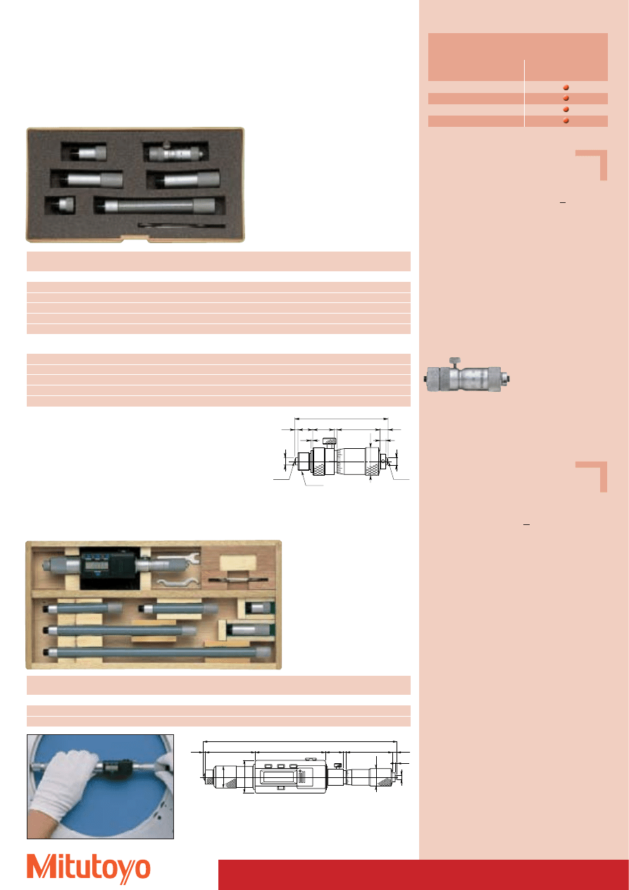
74
Inside Micrometers
Measuring range
No.
Number and size of extensions
Mass
mm
g
Accessories: Inside micrometer No. 137–011 (Standard in the set)
50– 150
137–201
3 (13, 25, 50 mm)
145
50– 300
137–202
5 (13, 25, 50, 50, 100 mm)
305
50– 500
137–203
6 (13, 25, 50, 50, 100, 200 mm)
460
50–1000
137–204
8 (13, 25, 50, 50, 100, 200, 200, 300 mm)
845
50–1500
137–205
10 (13, 25, 50, 50, 100, 200, 200, 200, 300, 300 mm)
1225
with carbide-tipped measuring surface
Accessories: Inside micrometer No. 137–013 (Standard in the set)
50– 150
137–206
3 (13, 25, 50 mm)
145
50– 300
137–207
5 (13, 25, 50, 50, 100 mm)
305
50– 500
137–208
6 (13, 25, 50, 50, 100, 200 mm)
460
50–1000
137–209
8 (13, 25, 50, 50, 100, 200, 200, 300 mm)
845
50–1500
137–210
10 (13, 25, 50, 50, 100, 200, 200, 200, 300, 300 mm)
1225
Measuring range
No.
Number and size of extensions
Mass
mm
g
Accessories: Inside micrometer No. 337–001 (Standard in the set)
200–1000
337–201
6 (25, 50, 100, 100, 200, 300 mm)
780
200–1500
337–202
7 (25, 50, 100, 200, 300, 300, 300 mm)
1150
1.8
Ø4
Ø18
4.8
47
3
18.5
72
52.9
1.8
200
35
Ø23
Ø4
50
23
11
8
4.8
2.2
3
Ø4
Ø1
5
1.5
1
SR10
M10x1
SR10
Series 337
“DIGIMATIC” Type, with data output
Extension Rod Type
Series 137
Analogue
Extension Rod Type
137–202
337–201
137–011
337–001
337–201
Functions
337–202
PRESET function
Zero-setting
DATA/HOLD
Data output
Micrometer series 337
Specifications
Accuracy:
Factory specification
Error limit: (3 + V +
L
50
) mm;
L in mm,
V = number of extensions
Graduation:
0,01 mm
Scales:
thimble and sleeve
satin chrome finish,
Ø 15 mm
Measuring spindle: spindle pitch 0,5 mm
Measuring span:
13 mm
Measuring surfaces: hardened
Extensions:
Ø 12,5 mm
Including box, key
Specifications
Accuracy:
Factory specification
Error limit:
(3 + V +
L
50
) mm;
L in mm,
V = number of extensions
Resolution:
0,001 mm, LCD display
Scales:
thimble and sleeve
satin chrome finish,
Ø 18 mm
Measuring spindle: spindle pitch 0,5 mm
Measuring span:
25 mm
Measuring surfaces: hardened
Extensions:
Ø 12,5 mm
Including box, key, 1 battery
Optional accessories
No. 937387
Signal cable (1 m)
No. 965013
Signal cable (2 m)
Consumable Spares
No. 938882
Battery SR-44
137–011
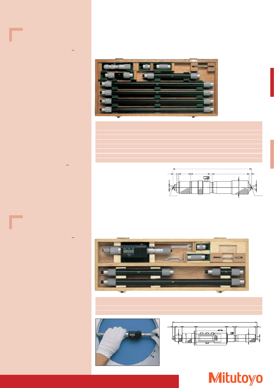
75
Specifications
Accuracy:
Factory specification
Error limit: (3 + V +
L
50
) mm;
L in mm,
V = number of extensions
Graduation:
0,01 mm
Scales:
thimble and sleeve
satin chrome finish,
Ø 18 mm
Measuring spindle: spindle pitch 0,5 mm
Measuring span:
25 mm
Measuring surfaces: carbide-tipped,
precision ground,
micro-lap finish
Extensions:
Ø 17 mm
Including box, key
Accessories (Standard in the set):
No. 139–001
Inside micrometer for 139–17x
No. 139–003
Inside micrometer for 139–203
No. 139–005
Inside micrometer for 139–204
Specifications for 139–203 / 139–204
As above, but:
Accuracy:
Factory specification
Error limit: (6 +
L
50
) mm;
L in mm
Scales:
Ø 13 mm
Measuring span:
10 mm (No. 139–203)
25 mm (No. 139–204)
Measuring surfaces: hardened,
precision ground,
micro-lap finish
Extensions:
Ø 10 mm
Specifications
Accuracy:
Factory specification
Error limit: (3 + V +
L
50
) mm;
L in mm,
V = number of extensions
Resolution:
0,001 mm, LCD display
Scales:
thimble and sleeve
satin chrome finish,
Ø 18 mm
Measuring spindle: spindle pitch 0,5 mm
Measuring span:
25 mm
Measuring surfaces: carbide-tipped,
precision ground,
micro-lap finish
Extensions:
Ø 17 mm
Including box, key, 1 battery
Accessories (Standard in the set):
No. 339–001
Inside micrometer for 339–291
Inside micrometer for 339–292
Optional accessories
No. 937387
Signal cable (1 m)
No. 965013
Signal cable (2 m)
Consumable Spares
No. 938882
Battery SR-44
Inside Micrometers
Series 139
Analogue
Extension Rod Type
139–177
Measuring range
No.
Number and size of extensions
Mass
mm
g
100– 500
139–173
4 (25, 50, 100, 200 mm)
490
100– 900
139–174
5 (25, 50, 100, 200, 400 mm)
790
100–1300
139–175
6 (25, 50, 100, 200, 400, 400 mm)
1090
100–1700
139–176
7 (25, 50, 100, 200, 400, 400, 400 mm)
1390
100–2100
139–177
8 (25, 50, 100, 200, 400, 400, 400, 400 mm)
1690
40– 300
139–203
8 (10, 20, 30, 60, 90, 110, 120, 130 mm)
240
100–1000
139–204
10 (25, 50, 75, 150, 225, 300, 350, 400, 425, 450 mm)
770
Series 339
“DIGIMATIC” Type, with data output
Extension Rod Type
339–291
339–001
Measuring range
No.
Number and size of extensions
Mass
mm
g
200–1000
339–291
5 (25, 50, 100, 200, 400 mm)
1100
200–2000
339–292
8 (25, 50, 100, 200, 200, 400, 400, 400 mm)
1850
Ø8
Ø18
4.5
2.5 15
34.5
72
200
18.5 3
47
3
35
Ø23
Ø16
47
3
3
25
15
2.5
4.5
Ø4
Ø8
100 - 125
SR10
SR10
Ø1
8
139–001
Micrometer series 339
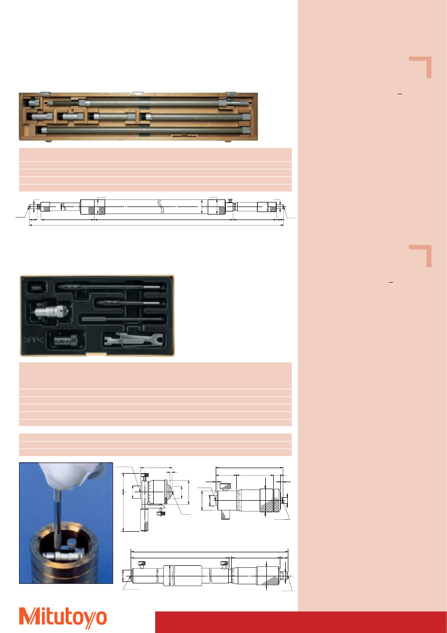
76
Specifications
Accuracy:
Factory specification
Error limit: (7 + V +
L
50
) mm;
L in mm,
V = number of extensions
Graduation:
0,01 mm
Scales:
thimble and sleeve
satin chrome finish,
Ø 21 mm
Measuring spindle: spindle pitch 0,5 mm
Measuring span:
50 mm
Measuring surfaces: carbide-tipped,
precision ground,
micro-lap finish
Extensions:
Ø 32 mm
Including box, key
Specifications
Accuracy:
Factory specification
Error limit: (6 +
L
50
) mm;
L in mm
Graduation:
0,01 mm
Scales:
thimble and sleeve
satin chrome finish
Measuring spindle: spindle pitch 0,5 mm
with spindle lock
Measuring surfaces: hardened
Including box, key
Inside Micrometers
140–158
Micrometer series 140
Measuring range
No.
Number and size of extensions
Mass
mm
g
1000–2000
140–157
5 (50, 100, 100, 200, 500 mm)
3700
1000–3000
140–158
6 (50, 100, 100, 200, 500, 1000 mm)
5200
1000–4000
140–159
7 (50, 100, 100, 200, 500, 1000, 1000 mm)
6700
1000–5000
140–160
8 (50, 100, 100, 200, 500, 1000, 1000, 1000 mm)
8260
Measuring
No.
Stroke
Measuring
No.
Accessories:
Mass
range
Screw
inserts
of tips
Inside micrometer
Standard in the set
mm
mm
No.
g
25– 50
141–101
7
2 ( 12 mm)
1 ( 6 mm)
141–001
60
50– 200
141–205
13
3 ( 50 mm)
2 (12,25 mm)
141–025
125
50– 300
141–206
13
5 ( 50 mm)
2 (12,25 mm)
141–025
275
200– 500
141–117
25
3 (100 mm)
2 (25 / 50 mm)
141–009
520
200–1000
141–118
25
8 (100 mm)
2 (25 / 50 mm)
141–009
1940
with carbide-tipped measuring surface
25– 50
141–103
7
2 ( 12 mm)
1 ( 6 mm)
141–003
60
50– 200
141–211
13
3 ( 50 mm)
2 (12,25 mm)
141–027
125
50– 300
141–212
13
5 ( 50 mm)
2 (12,25 mm)
141–027
275
Series 141
With interchangeable measuring inserts for different measuring ranges.
Practical handle for measuring deep bores.
SR10
Ø6.5
43.5
13.7
23
5
1.8
1.2
Ø4
Ø5
Ø15
12
181.5
123
47
3
Ø11
Ø20
Ø18
Ø8
8.5
SR10
Ø7
24
12
Ø4.5
Ø9
20.5
2
Ø8
Ø16
SR8
1000 - 1050
SR10
SR10
101
15
16.5
Ø 8
Ø 8
Ø21
Ø 33
Ø1
9
699
Ø 33
Ø3
2
175.5
141–001/003
141–025 /141–027
141–009
141–205
Series 140
For large measuring ranges
Extension Rod Type
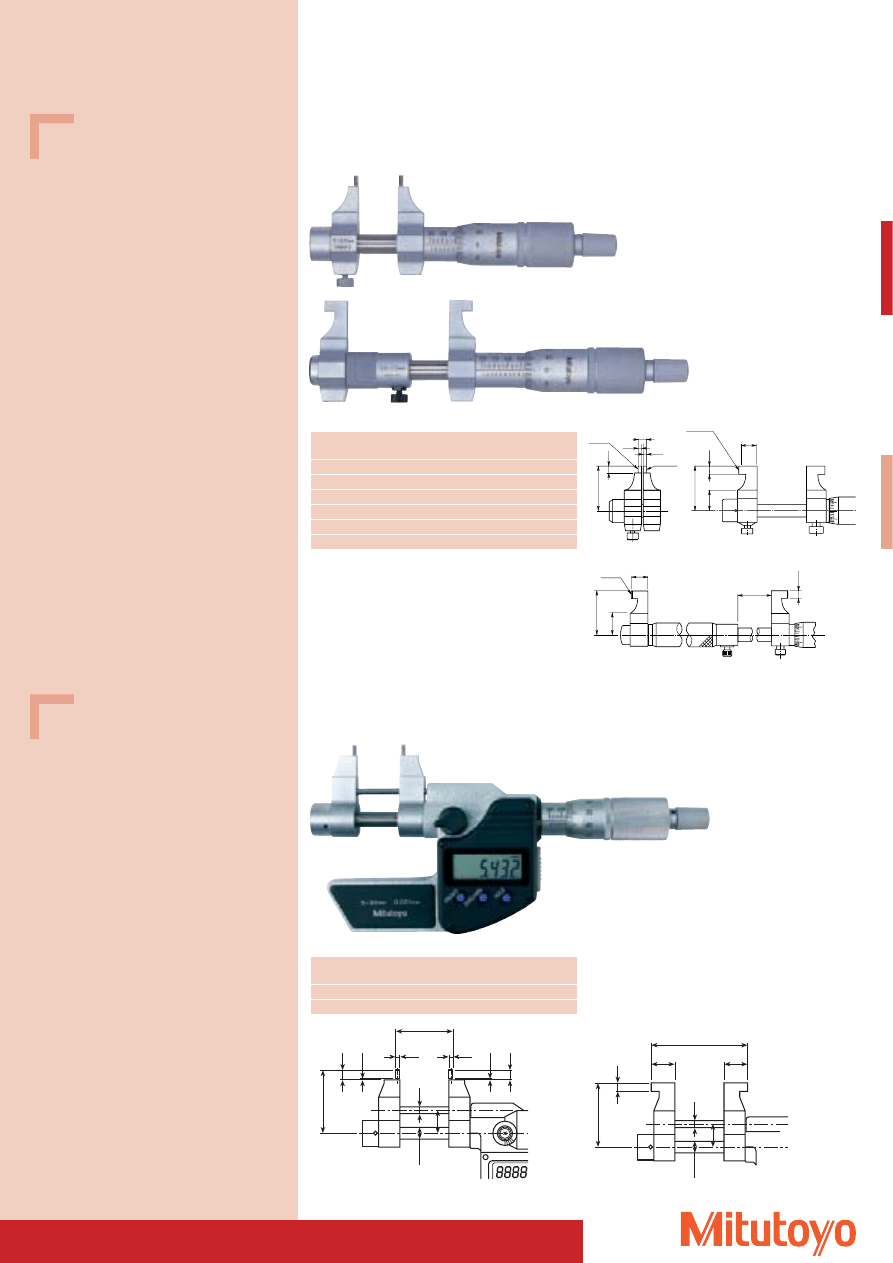
77
Specifications
Accuracy:
Factory specification
Graduation:
0,01 mm
Scales:
thimble and sleeve
satin chrome finish,
Ø 18 mm
Measuring spindle: spindle pitch 0,5 mm
with spindle lock
Measuring surfaces: carbide-tipped,
precision ground,
micro-lap finish
Measuring force:
1–6 N
Including box, key
Specifications
Accuracy:
Factory specification
Resolution:
0,001 mm, LCD display
Scales:
thimble and sleeve
satin chrome finish,
Ø 18 mm
Measuring spindle: spindle pitch 0,5 mm
with spindle lock
Measuring surfaces: carbide-tipped,
precision ground,
micro-lap finish
Measuring force:
1–6 N
Including box, key, 1 battery
Optional accessories
No. 05CZA662
Signal cable (1 m)
No. 05CZA663
Signal cable (2 m)
Consumable Spares
No. 938882
Battery SR-44
145–185
145–187
R2.2
27.5
4.5
R2.2
5
Ø2
Ø2
R12
9.3
4.3
27.5
12.5
Inside Micrometers
• With measuring jaws.
Series 145
Analogue
Measuring range
No.
Error limit
Mass
mm
mm
g
5– 30
145–185
5
130
25– 50
145–186
6
140
50– 75
145–187
7
160
75–100
145–188
8
180
100–125
145–189
9
210
125–150
145–190
9
230
345–250
Series 345
“DIGIMATIC” Type, with data output
Measuring range
No.
Error limit
Mass
mm
mm
g
5–30
345–250
5
305
25–50
345–251
6
310
Measuring range 5–30 mm Measuring range 25–50 mm
Measuring range > 50 mm
31.4
4.5
12.5
27.5
R12
9.3
32
4.
5
1
1
4.
5
12
Ø
6.35
Ø 2
Ø 2
30
Ø 2.
4
33
4.
3
Ø
6.35
12
Ø 2.
4
12.2
12.2
50
345–250 (Measuring range 5–30 mm)
345–251 (Measuring range 25–50 mm)
78
Series 177
micro-lap finish, steel and ceramic
177–146
Nominal size
Steel
Ceramic
Cylindricity
Ø
No.
No.
(Factory specification)
mm
mm
1,00
177–220
1
1,10
177–222
1
1,20
177–225
1
1,30
177–227
1
1,40
177–230
1
1,75
177–236
1
2,00
177–239
1
2,25
177–242
1
2,50
177–208
1
2,75
177–246
1
3,00
177–248
1
3,25
177–250
1
3,50
177–252
1
3,75
177–255
1
4,00
177–204
1
4,50
177–257
1
5,00
177–205
1
5,50
177–263
1
6,00
177–267
177–420
1
6,50
177–271
1
7,00
177–275
1
8,00
177–125
177–423
1
10,00
177–126
177–424
1
12,00
177–284
177–425
1
Nominal size
Steel
Ceramic
Cylindricity
Ø
No.
No.
(Factory specification)
mm
mm
16,00
177–177
177–427
1
20,00
177–286
177–429
1
25,00
177–139
177–430
1
30,00
177–288
177–431
1
35,00
177–140
177–432
1
40,00
177–290
177–433
1
45,00
177–178
177–434
1
50,00
177–146
1
60,00
177–292
1
62,00
177–314
1,5
70,00
177–147
1,5
80,00
177–294
1,5
87,00
177–318
1,5
90,00
177–148
1,5
100,00
177–296
2
125,00
177–298
2
150,00
177–300
2
175,00
177–302
2,5
200,00
177–304
2,5
225,00
177–306
2,5
250,00
177–308
3
275,00
177–310
3
300,00
177–312
3
“Setting Rings” made of steel and ceramic
• The actual size, which can deviate from the nominal value (for rings with diameters 1 through 45 mm)
by ± 0,01 mm respectively by ± 0,02 mm (for rings with diameters over 50 mm) is marked on the
setting ring with 3 decimal digits.
• These setting rings are used for the adjustment of Mitutoyo inside micrometers.
Please order setting rings with factory certificate with suffix -12 after the item no.
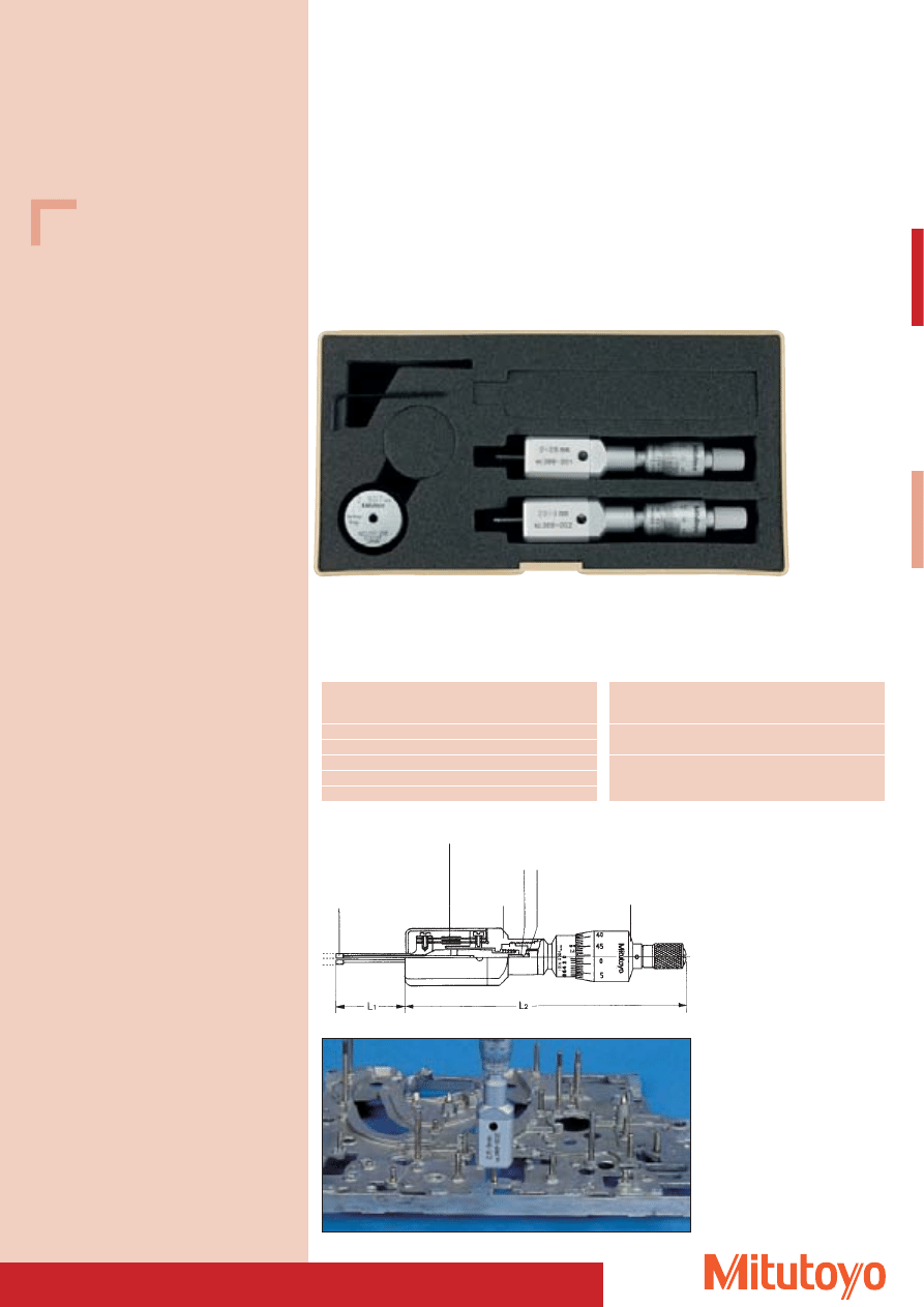
79
Inside Micrometer “Mini-Holtest”
• For fast direct measuring of small bores Mitutoyo developed the “Mini-Holtest”.
• The device features two built-in springs, that allow for precise measurements in extremely small bores.
All measuring surfaces are carbide-tipped to protect against wear.
Series 368
Separate instruments
Sets
368–906
Measuring
No.
L
1
L
2
Mass
range
mm
mm
mm
g
2 –2,5
368–001
12
93
88
2,5–3
368–002
12
93
88
3 –4
368–003
22
93
91
4 –5
368–004
22
93
91
5 –6
368–005
22
93
91
Measuring
Set
Contents
Setting ring
Mass
range
Instruments
mm
No.
No.
No.
g
2–3
368–906
368–001
177–208
310
368–002
3–6
368–907
368–003
177–204
505
368–004
177–205
368–005
Parallel leaf spring
Carbide pin Carbide ball
Measuring sur-
faces
Casing
Measuring Tip
Specifications
Accuracy:
Factory specification
Error limit: 2 mm
Graduation:
0,001 mm
Scales:
thimble and sleeve
satin chrome finish,
Ø 17 mm
Measuring spindle: spindle pitch 0,5 mm
Measuring surfaces: carbide-tipped
Measuring force:
5–10 N
Including box, key
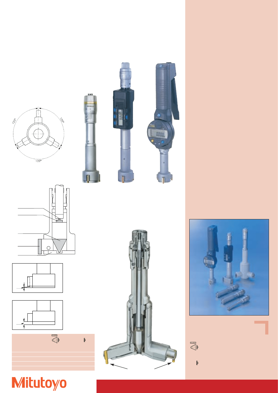
80
Series 468
“DIGIMATIC”
Type
Series 568
“BOREMATIC”
Type
Three-Point Inside Micrometer “Holtest”
• The instrument contacts the wall of the bore to be measured at three points.
• This system facilitates operation and increases, thanks to the measuring pins arranged at a distance
of 120°, the accuracy of measurement compared to traditional two-point devices.
• By turning the ratchet the “Holtest” automatically centers in the bore which makes measurement fast
and easy to perform without loss in precision.
Measuring range
Dimansion „h“
Dimansion „h“
mm
mm
mm
6– 12
2,0
–
12– 30
0,3
2,6
30–100
0,3
3,4
100–300
12,4
19,6
Key to symbols
Measuring surfaces titanium-coated or
carbide. Carbide taper and contact point.
Measuring surfaces and tapers, hardened
steel. Contact surfaces and points are
carbide-tipped.
Series 368
Standard
Type
Analogue
Series 368
Measuring can be
taken nearly down
to the bottom of
the bore.
Contact point
Contact surface
Taper
Measuring surface
Cover
368–1XX
368–7XX
titanium coated
h
h
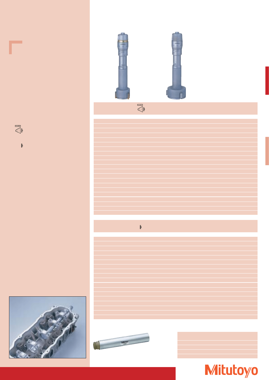
81
Three-Point Inside Micrometer “Holtest”
• Delivered with factory certificate.
Series 368
Analogue
Measuring range
No.
Depth
Depth
Mass
without extension
with extension
mm
mm
mm
g
Measuring surfaces titanium-coated or carbide. Carbide taper and contact point.
6– 8
368–101–10*
59
159
60
8– 10
368–102–10*
59
159
60
10– 12
368–103–10*
59
159
60
12– 16
368–164
80
230
150
16– 20
368–165
80
230
160
20– 25
368–166
90
240
260
25– 30
368–167
90
240
280
30– 40
368–168
98
248
290
40– 50
368–169
98
248
330
50– 63
368–170
105
255
440
62– 75
368–171
105
255
450
75– 88
368–172
105
255
570
87–100
368–173
105
255
580
100–125
368–174
158
308
1030
125–150
368–175
158
308
1120
150–175
368–176
158
308
1210
175–200
368–177
158
308
1320
200–225
368–178
158
308
1430
225–250
368–179
158
308
1550
250–275
368–180
158
308
1700
275–300
368–181
158
308
1870
* Measuring surfaces up to 12 mm carbide
Measuring range
No.
Depth
Depth
Mass
without extension
with extension
mm
mm
mm
g
Measuring surfaces and tapers, hardened steel. Contact surfaces and points are carbide-tipped.
12– 16
368–764
80
230
150
16– 20
368–765
80
230
150
20– 25
368–766
90
240
260
25– 30
368–767
90
240
280
30– 40
368–768
98
248
290
40– 50
368–769
98
248
330
50– 63
368–770
105
255
440
62– 75
368–771
105
255
450
75– 88
368–772
105
255
560
87–100
368–773
105
255
570
100–125
368–774
158
308
1020
125–150
368–775
158
308
1110
150–175
368–776
158
308
1200
175–200
368–777
158
308
1300
200–225
368–778
158
308
1420
225–250
368–779
158
308
1540
250–275
368–780
158
308
1690
275–300
368–781
158
308
1860
Specifications
Accuracy:
DIN 863/4*
* The given precision values require close contact
of the measuring surfaces.
Graduation:
up to
12 mm: 0,001 mm
over 12 mm: 0,005 mm
Scales:
thimble and sleeve
satin chrome finish,
up to
12 mm: Ø 17 mm
over 12 mm: Ø 23 mm
Measuring spindle: spindle pitch 0,5 mm
Including box, key, factory certificate
Measuring surfaces titanium-coated or
carbide. Carbide taper and contact point.
Measuring surfaces and tapers, hardened
steel. Contact surfaces and points are
carbide-tipped.
No.
Length
For measuring range
Mass
mm
g
952322
100
6– 12 mm
13
952621
150
12– 20 mm
100
952622
150
20– 50 mm
238
952623
150
50–300 mm
264
952623
368–1XX
368–7XX
Extensions for Series 368 / 468 / 568
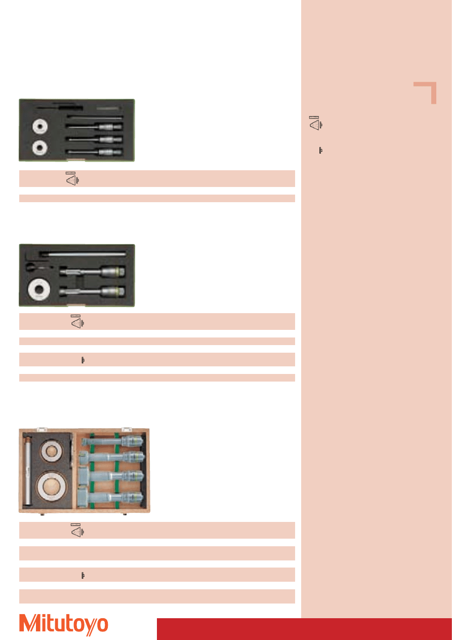
82
Specifications
Measuring surfaces titanium-coated or
carbide. Carbide taper and contact point.
Measuring surfaces and tapers, hardened
steel. Contact surfaces and points are
carbide-tipped.
Three-Point Inside Micrometer “Holtest”
• Analogue in Sets.
• Delivered with factory certificate.
Series 368
368–901–10
Measuring
Set
Contents
Setting ring
Setting ring Extensions Length of the
range mm
No.
Device No.
No.
Ø mm
No.
extensions mm
Measurement surfaces as well as otheras well as other wearing parts are carbide-tipped.
6–12
368–901–10
368–101–10 / 368–102–10 / 368–103–10 177–125 / 177–126 8 / 10
952322
100
Measuring
Set
Contents
Setting ring
Setting ring
Extensions
Length of the
range mm
No.
Device No.
No.
Ø mm
No.
extensions mm
Measuring surfaces titanium coated as well as other wearing parts are carbide.
12–20
368–912
368–164 / 368–165
177–177
16
952621
150
Measuring
Set
Contents
Setting ring
Setting ring
Extensions
Length of the
range mm
No.
Device No.
No.
Ø mm
No.
extensions mm
Measuring surfaces and taper, hardened steel. Contact surfaces and points are carbide-tipped.
12–20
368–991
368–764 / 368–765
177–177
16
952621
150
Series 368
368–912
Measuring
Set
Contents
Setting ring
Setting ring
Extensions
Length of the
range mm
No.
Device No.
No.
Ø mm
No.
extensions mm
Measuring surfaces titanium coated as well as other wearing parts are carbide.
20–50
368–913
368–166 / 368–167
177–139 / 177–290
25 / 40
952622
150
368–168 / 368–169
Measuring
Set
Contents
Setting ring
Setting ring
Extensions
Length of the
range mm
No.
Device No.
No.
Ø mm
No.
extensions mm
Measuring surfaces and taper are hardened steel. Contact surfaces and points are carbide-tipped.
20–50
368–992
368–766 / 368–767
177–139 / 177–290
25 / 40
952622
150
368–768 / 368–769
Series 368
368–913
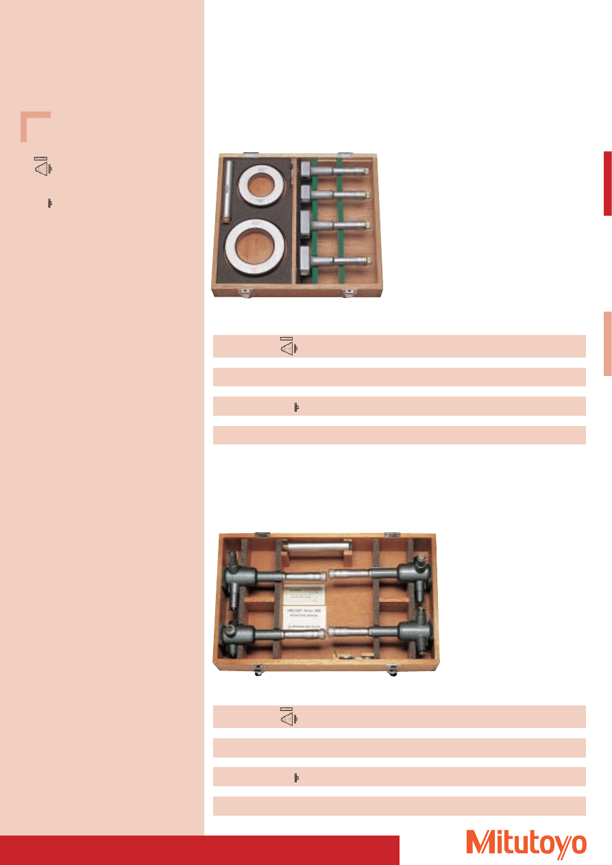
83
Specifications
Measuring surfaces titanium-coated or
carbide. Carbide taper and contact point.
Measuring surfaces and tapers, hardened
steel. Contact surfaces and points are
carbide-tipped.
Three-Point Inside Micrometer “Holtest”
• Analogue in Sets.
• Delivered with factory certificate.
Measuring
Set
Contents
Setting ring
Setting ring
Extensions
Length of the
range mm
No.
Device No.
No.
Ø mm
No.
extensions mm
Measuring surfaces titanium coated as well as other wearing parts are carbide.
50–100
368–914
368–170 / 368–171
177–314 / 177–318
62 / 87
952623
150
368–172 / 368–173
Measuring
Set
Contents
Setting ring
Setting ring
Extensions
Length of the
range mm
No.
Device No.
No.
Ø mm
No.
extensions mm
Measuring surfaces and taper are hardened steel. Contact surfaces and points are carbide-tipped.
50–100
368–993
368–770 / 368–771
177–314 / 177–318
62 / 87
952623
150
368–772 / 368–773
Series 368
368–914
Measuring
Set
Contents
Setting ring
Setting ring
Extensions
Length of the
range mm
No.
Device No.
No.
Ø mm
No.
extensions mm
Measuring surfaces titanium coated as well as other wearing parts are carbide.
100–200
368–915
368–174 / 368–175
177–298 / 177–302
125 / 175
952623
150
368–176 / 368–177
Measuring
Set
Contents
Setting ring
Setting ring
Extensions
Length of the
range mm
No.
Device No.
No.
Ø mm
No.
extensions mm
Measuring surfaces and taper are hardened steel. Contact surfaces and points are carbide-tipped.
100–200
368–994
368–774 / 368–775
177–298 / 177–302
125 / 175
952623
150
368–776 / 368–777
Series 368
368–915
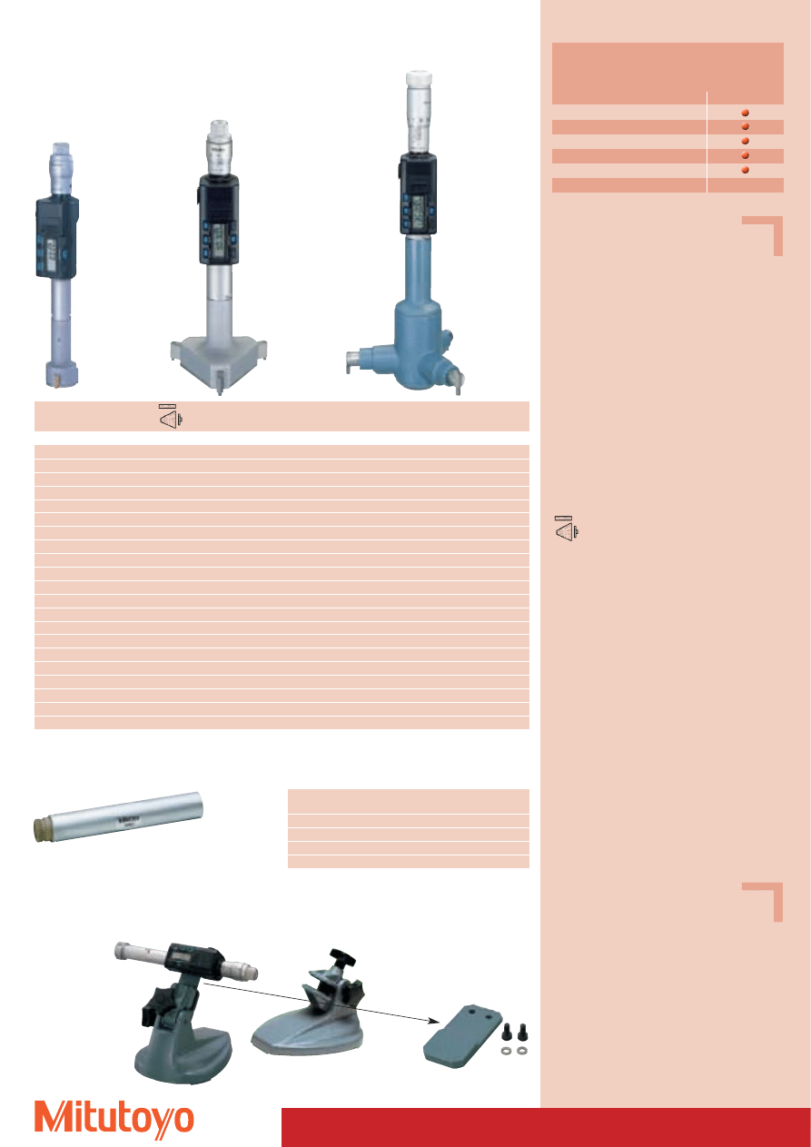
468–143–10
468–137–10
468–145–10
Measuring range
No.
Depth without extension
Depth with extension
Mass
mm
mm
mm
g
Measuring surfaces titanium-coated or carbide. Carbide taper and contact point.
6– 8
468–131*
45
145
400
8– 10
468–132*
45
145
400
10– 12
468–133*
45
145
400
12– 16
468–134–10
76
226
430
16– 20
468–135–10
76
226
430
20– 25
468–136–10
88
238
500
25– 30
468–137–10
88
238
510
30– 40
468–138–10
102
252
510
40– 50
468–139–10
102
252
530
50– 63
468–140–10
105
255
650
62– 75
468–141–10
105
255
660
75– 88
468–142–10
105
255
990
87–100
468–143–10
105
255
1000
100–125
468–144–10
151
301
970
125–150
468–145–10
151
301
1060
150–175
468–146–10
151
301
1150
175–200
468–147–10
151
301
1240
200–225
468–148–10
151
301
1330
225–250
468–149–10
151
301
1420
250–275
468–150–10
151
301
1510
275–300
468–151–10
151
301
1600
84
Specifications
Accuracy: DIN 863/4*
* The given precision values require close contact
of the measuring surfaces.
Resolution: 0,001 mm
6 digit LCD display
Including box, key, 1 battery SR-44,
factory certificate
Optional accessories
No. 937387
Signal cable (1 m)
No. 965013
Signal cable (2 m)
Consumable Spares
No. 938882
Battery SR-44
Measuring surfaces titanium-coated or
carbide. Carbide taper and contact point.
Three-Point Internal Micrometer “DIGIMATIC-Holtest”
• Delivered with factory certificate.
Functions
Series 468
PRESET function
Zero-setting
DATA/HOLD
Weak battery alarm
Automatic switch off
Specifications
No. 982693
Plate
Optional accessories
No. 156–101 M
Recommended base
Series 468
with data output
Holder for “DIGIMATIC”-Holtest
Three-Point Internal Micrometer
Series 468
982693
Extensions for Series 368 / 468 / 568
No.
Length
For measuring range
Mass
mm
g
952322
100
6– 12 mm
13
952621
150
12– 20 mm
100
952622
150
20– 50 mm
238
952623
150
50–300 mm
264
952623
* Measuring surfaces up to 12 mm carbide
982693 + 156–101 M (Optional accessories)
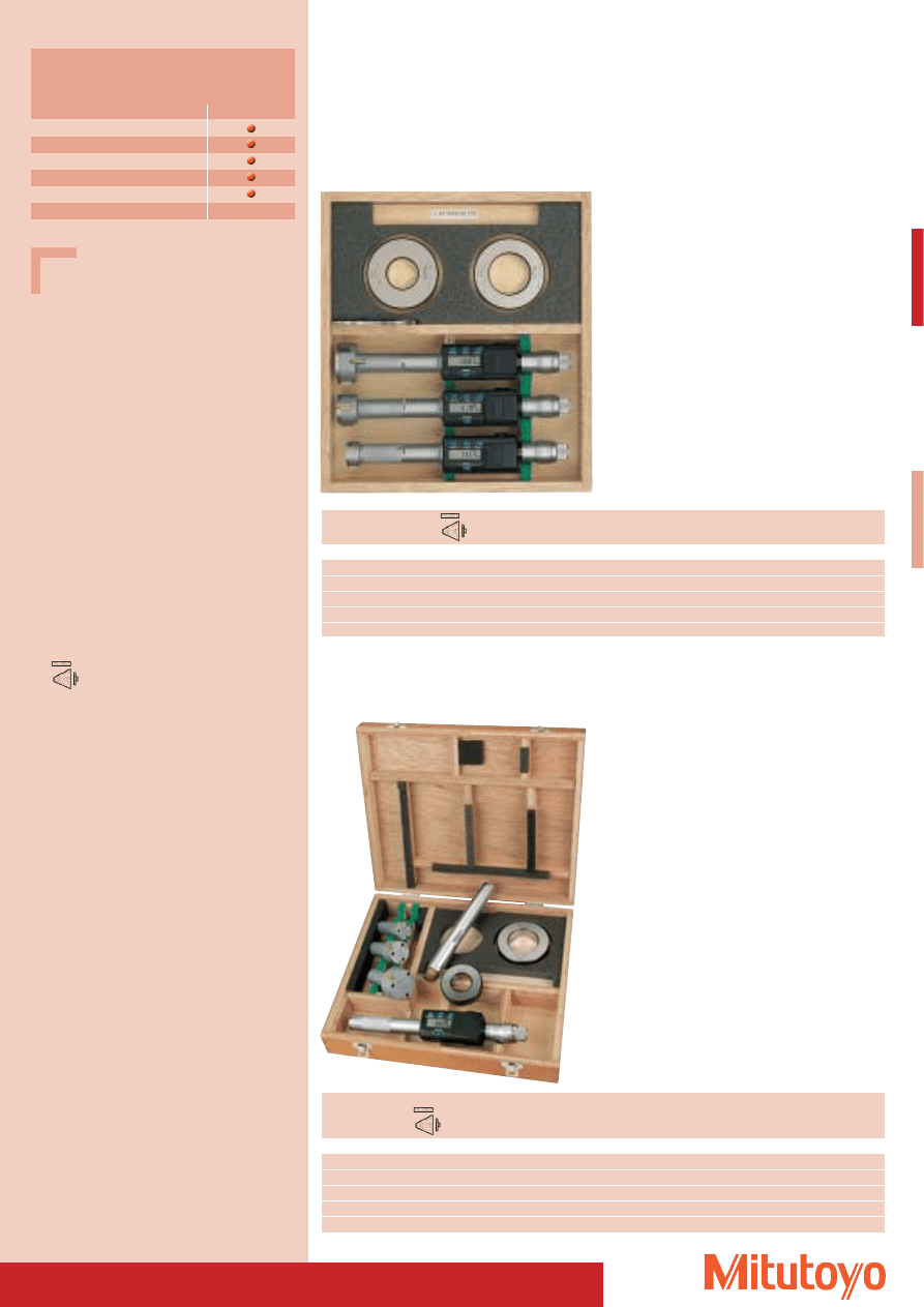
85
Specifications
Accuracy: DIN 863/4*
* The given precision values require close contact
of the measuring surfaces.
Resolution: 0,001 mm
6 digit LCD display
Including box, key, 1 battery SR-44, setting ring,
extensions (only 468–953, 468–954),
factory certificate
Optional accessories
No. 937387
Signal cable (1 m)
No. 965013
Signal cable (2 m)
Extensions see page 84
Holder for in turn measurements
see page 84
Consumable Spares
No. 938882
Battery SR-44
Measuring surfaces titanium-coated or
carbide. Carbide taper and contact point.
Three-Point Internal Micrometer “DIGIMATIC-Holtest”
• Digital, in Sets.
468–963–10
Series 468
with data output
468–953–10
Series 468
With interchangeable measuring probe heads, with data output
Measuring range
Set
Contents
Setting ring
Setting ring
mm
No.
Device No.
No.
Ø mm
Measuring surfaces titanium-coated or carbide. Carbide taper and contact point.
6– 12
468–961*
468–131 / 468–132 / 468–133
177–125 / 177–126
8 / 10
12– 25
468–962–10
468–134–10 / 468–135–10 / 468–136–10
177–177 / 177–286
16 / 20
25– 50
468–963–10
468–137–10 / 468–138–10 / 468–139–10
177–288 / 177–290
30 / 40
50– 75
468–964–10
468–140–10 / 468–141–10
177–314
62
75–100
468–965–10
468–142–10 / 468–143–10
177–318
87
Measuring
Set
Individual
Setting
Setting
Extensions Length of the
range
ranges
ring
ring
extensions
mm
No.
mm
No.
Ø mm
No.
mm
Measuring surfaces titanium-coated or carbide. Carbide taper and contact point.
6– 12
468–951*
6–8, 8–10, 10–12
177–125 / 177–126
8 / 10
952322
100
12– 20
468–952–10
12–16, 16–20
177–177
16
952621
150
20– 50
468–953–10
20–25, 25–30, 30–40, 40–50
177–139 / 177–290
25 / 40
952622
150
50–100
468–954–10
50–63, 62–75, 75–88, 87–100
177–314 / 177–318
62 / 87
952623
150
100–200
468–955–10
100–125, 125–150, 150–175, 175–200
177–298 / 177–302
125 / 175
952623
150
Functions
Series 468
PRESET function
Zero-setting
DATA/HOLD
Weak battery alarm
Automatic switch off
* Measuring surfaces up to 12 mm carbide
* Measuring surfaces up to 12 mm carbide
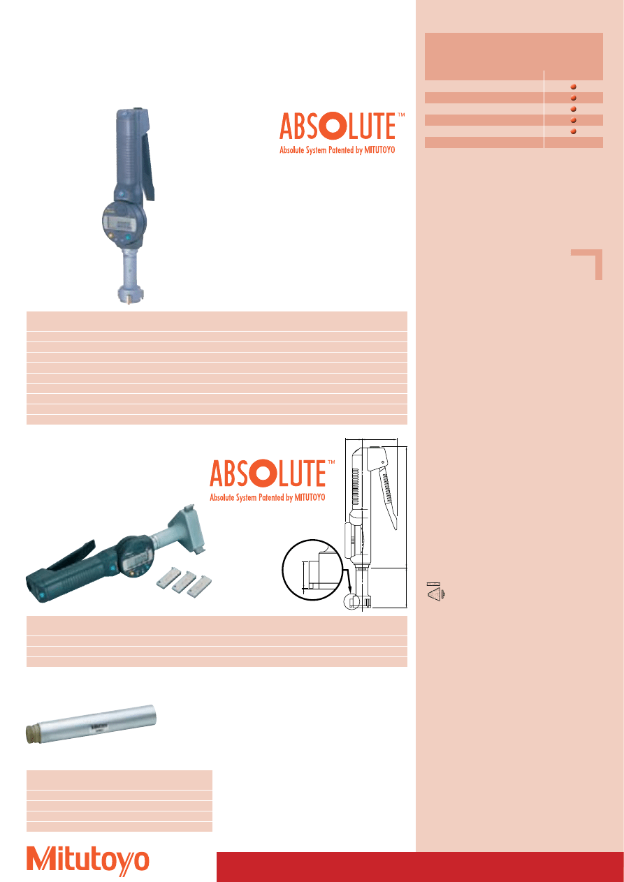
86
Specifications
6 digit LDC display, may be rotated by 330° for
convenient position
Resolution:
0,001 mm
Accuracy:
Factory specification
Error limit:
0,005 mm
(Measuring range 6–20 mm)
0,006 mm
(Measuring range 20–125 mm)
The indicated data for accuracy
require close contact of all measur-
ing surfaces.
Measuring
surfaces:
Up to 12 mm measuring range
carbide,
from 12 mm measuring range
titanium coated
Power supply: 1 battery SR-44
Optional accessories
No. 937387
Signal cable (1 m)
No. 965013
Signal cable (2 m)
Consumable Spares
No. 938882
Battery SR-44
Measuring surfaces titanium-coated or
carbide. Carbide taper and contact point.
L
202
b
c
a
28.5
Series 568
with data output
A
BOREMATIC
Three-Point Internal Micrometer
• Worldwide unique electronic three-point internal micrometer with built-in absolute scale.
• Delivered with factory certificate.
568–339–10
Measuring range
No.
L
a
b
c
Mass
mm
mm
mm
mm
mm
g
6– 8
568–331*
83,0
58
2,5
2,0
480
8–10
568–332*
83,0
58
2,5
2,0
485
10–12
568–333*
83,0
58
2,5
2,0
485
12–16
568–334–10
52,6
58
6,3
0,3
475
16–20
568–335–10
52,6
58
6,3
0,3
480
20–25
568–336–10
58,2
58
8,8
0,3
540
25–30
568–337–10
58,2
58
8,8
0,3
555
30–40
568–338–10
67,3
58
14,0
0,3
565
40–50
568–339–10
67,3
58
14,0
0,3
610
568–347–10
Series 568
with data output,
with interchangeable measuring tips
Measuring range
No.
L
a
b
c
Mass
mm
mm
mm
mm
mm
g
50– 63 / 62– 75
568–346–10
74,8
67
17,0
0,3
780
75– 88 / 87–100
568–347–10
74,8
67
17,0
0,3
850
100–113 / 112–125
568–348–10
74,8
67
17,0
0,3
970
Functions
Series 568
ON/OFF
ZERO/ABS-switching
PRESET
Input of tolerance limits
Data output
Extensions for Series 368 / 468 / 568
No.
Length
For measuring range
Mass
mm
g
952322
100
6– 12 mm
13
952621
150
12– 20 mm
100
952622
150
20– 50 mm
238
952623
150
50–300 mm
264
952623
* Measuring surfaces up to 12 mm carbide
TM
Patent numbers see page 464
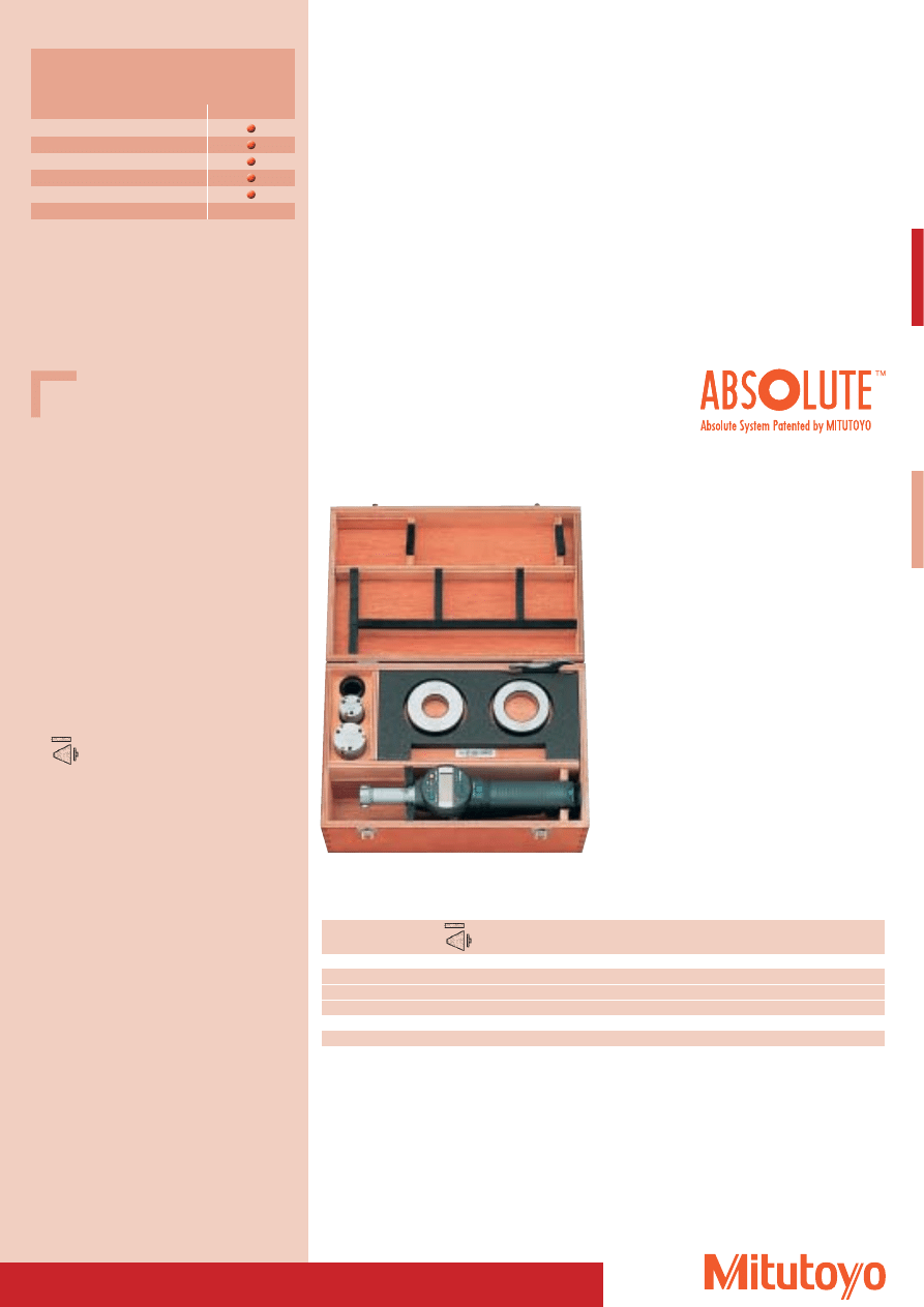
87
Specifications
6 digit LDC display, may be rotated by 330° for
convenient position
Resolution:
0,001 mm
Accuracy:
Factory specification
Error limit:
0,005 mm
(Measuring range 6–20 mm)
0,006 mm
(Measuring range 20–125 mm)
The indicated data for accuracy
require close contact of all
measuring surfaces.
Measuring
surfaces:
Up to 12 mm measuring range
carbide,
from 12 mm measuring range
titanium coated
Power supply: 1 battery SR-44
Measuring surfaces titanium-coated or
carbide. Carbide taper and contact point.
A
BOREMATIC
Three-Point Internal Micrometer
• Digital, in Sets.
• Delivered with factory certificate.
568–973–10
Series 568
with data output
Measuring range
Set
Mass
Individual ranges
Setting ring
Setting ring
mm
No.
kg
mm
No.
Ø mm
Measuring surfaces titanium-coated or carbide. Carbide taper and contact point.
6– 12
568–971*
0,6
6–8, 8–10, 10–12
177–125 / 177–126
8 / 10
12– 25
568–972–10
0,8
12–16, 16–20, 20–25
177–177 / 177–286
16 / 20
25– 50
568–973–10
1,3
25–30, 30–40, 40–50
177–288 / 177–290
30 / 40
with interchangeable measuring tips
50–100
568–975–10
3,5
50–63, 62–75, 75–88, 87–100
177–314 / 177–318
62 / 87
Functions
Series 568
ON/OFF
ZERO/ABS-switching
PRESET
Input of tolerance limits
Data output
* Measuring surfaces up to 12 mm carbide
TM
Patent numbers see page 464
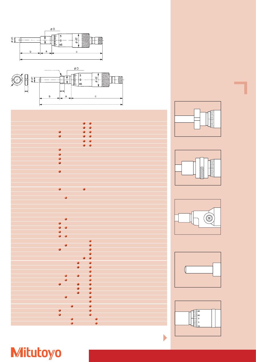
88
Survey of Micrometer Heads
Measuring
without
with
1)
2)
3)
4)
5)
6)
7)
Graduation Ø D
Ø d1
a
b
c
Ø d2
range
set nut
set nut
No.
No.
0– 1
110–105
0,001
12
8
12,7 25
62,5
21
0– 1
110–106
0,0001
12
8
12,7 25
62,5
21
0– 1
110–107
0,001
12
8
12,7 25
62,5
21
0– 1
110–108
0,0001
12
8
12,7 25
62,5
21
0– 2,5
110–101
0,001
12
8
12,7 25
70
21
0– 2,5
110–102
0,0001
12
8
12,7 25
70
21
0– 5
148–215
148–216
0,02
3,5
2
5
6,5
20,5
6
0– 6,5
148–142
148–143
0,002
9,5
5
9,5 14
31,5
13
0– 6,5
148–242
148–243
0,002
6
3,5
6
9
21,9
9,3
0– 6,5
148–342
148–343
0,002
9,5
6,35
9,5
9
23,5
15
0– 6,5
148–201
148–203
0,01
6
3,5
6
9
21,7
9
0– 6,5
148–205
148–207
0,01
6
3,5
7,5
7,5
21,7
9
0– 6,5
148–301
148–302
0,01
9,5
6,35
9,5
9
23,5
15
0– 6,5
148–303
148–304
0,01
9,5
6,35
9,5
9
23,5
20
0– 6,5
148–305
148–306
0,01
9,5
6,35
9,5
9
23,5
29
0–13
110–502
0,0005
9,5
5
15
15
67
13
0–13
148–104
148–103
0,01
9,5
5
9,5 17,5
31,5
13
0–13
148–121
148–120
0,01
9,5
5
9,5 17,5
40,1
13
0–13
148–307
148–308
0,01
9,5
6,35
9,5 15,5
30
15
0–13
148–309
148–310
0,01
9,5
6,35
9,5 15,5
30
20
0–13
148–311
148–312
0,01
9,5
6,35
9,5 15,5
30
29
0–13
148–503
148–508
0,01
9,5
5
9,5 15,5
37
13
0–13
148–506
148–504
0,01
9,5
5
9,5 15,5
45,6
13
0–13
148–801
148–802
0,01
9,5
5
9,5 17,5
31,5
13
0–13
148–803
148–804
0,01
9,5
5
9,5 17,5
40,1
13
0–13
148–853
0,01
9,5
5
9,5 15,5
37
13
0–13
148–854
0,01
9,5
5
9,5 15,5
45,5
13
0–15
149–132
149–131
0,01
9,5
6,35 15
17
43,5
15
0–15
149–183
149–184
0,01
9,5
6,35
9,5 17
49
15
0–15
149–801
149–802
0,01
9,5
6,35 15
17
43,5
15
0–15
152–101
0,01
12
8
16
18
60
30
0–15
153–101
0,01
9,5
6,35 10
17
59,5
13,3
0–25
150–190
150–189
0,001
10
6,35 15
27
67
18
0–25
150–192
150–191
0,01
10
6,35 15
27
67
18
0–25
150–196
150–195
0,01
10
6,35 15
27
54
18
0–25
150–209
150–210
0,01
10
6,35 15
27
78,5
18
0–25
150–211
150–212
0,01
10
6,35 15
27
65
18
0–25
150–801
150–802
0,01
10
6,35 15
27
67
18
0–25
151–222
151–221
0,001
12
8
29
34
70
21
0–25
151–224
151–223
0,01
12
8
29
34
70
21
0–25
151–225
151–226
0,01
12
8
19
34,5
66
21
0–25
152–102
0,01
12
8
16
28
69
30
0–25–0
152–348
0,002
12
8
29
34
66
49
0–25
152–401
0,001
18
8
14
41,7
84,2
49
0–25
152–402
0,001
18
8
14
41,7
84,2
49
0–25–0
152–389
0,005
18
6,35 14
38,7
66,3
49
0–25–0
152–390
0,005
18
6,35 14
38,7
66,3
49
Total length l = a + b + c
1) spherical measuring surface
2) with lock
3) reversal reading
4) with ratchet
5) with non-rotating spindle
6) carbide-tipped
7) non-rotating measuring surface
Continued on next page
Shaft with clamping screw
With clamping device
With spherical measuring surface
With reversable scale
Description of built-in micrometers
With clamping device
250–301 / 350–5xx
Set nut
Total length l = a + b + c
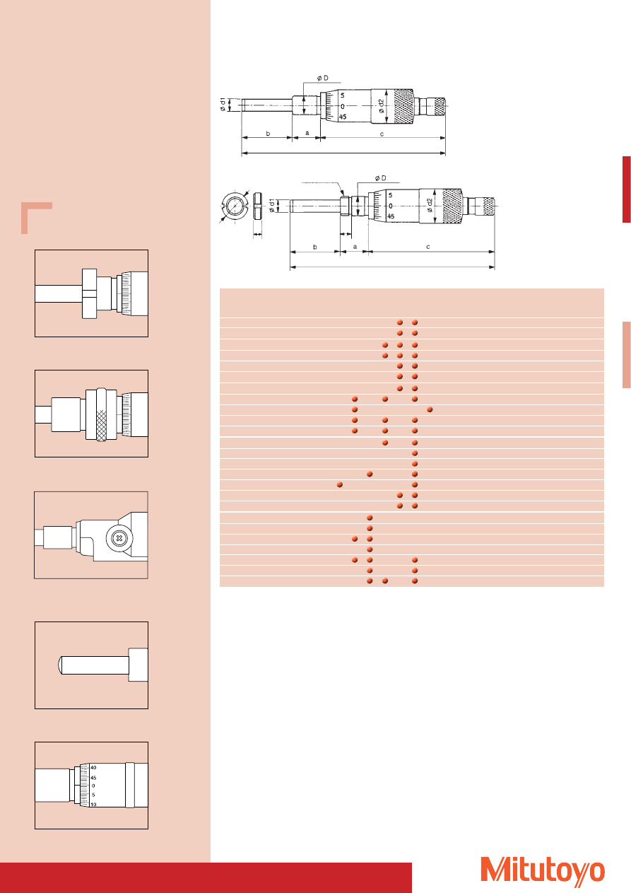
89
Measuring
without
with
1)
2)
3)
4)
5)
6)
7)
Gra-
Re-
Ø D Ø d1
a
b
c
Ø d2
range
set nut
set nut
duation solution
No.
No.
0 –15
227–241
–
0,001
12
6,35 15
17
141,7 24,5
0 –15
227–242
–
0,001
12
6,35 15
17
141,7 24,5
0 –25
153–201
0,01
–
12
8
10
27
88
18
0 –25
153–202
0,001
–
12
8
10
27
88
18
0 –25
153–203
0,01
–
12
8
10
27
71
18
0 –25
153–204
0,001
–
12
8
10
27
71
18
0 –25
164–171
–
0,001
18
8
14
2
104,5 27
0 –25
250–301
0,01
–
10
6,35 15
27
94
18
0 –25
350–261
0,01
0,001
12
6,35 14
38,7 101
18
0 –25
350–271
0,01
0,001
12
6,35 16
27
112,5 18
0 –25
350–272
0,01
0,001
12
6,35 16
27
112,5 18
0 –50
151–256
151–255
0,01
–
12
8
29
59
103
21
0 –50
151–260
151–259
0,01
–
12
8
29
59
90
21
0 –50
152–103
0,01
–
12
8
16
53
94
30
0 –50–0 152–380
0,002
–
12
8
29
34
66
49
0 –50
164–122
–
0,001
12
8
18
60
133
56
0 –50
164–161
–
0,001
18 11
14
15
143
49
0 –50
197–101
0,005
–
18
8
14
65
64
49
6,5– 0
148–209
148–211
0,01
–
6
3,5
7,5 7,5
21,7
9
13 – 0
148–821
148–822
0,01
–
9,5 5
9,5 17,5
31,5 13
13 – 0
148–823
148–824
0,01
–
9,5 5
9,5 17,5
40,1 13
13 – 0
148–863
0,01
–
9,5 5
9,5 15,5
37
13
13 – 0
148–864
0,01
–
9,5 5
9,5 15,5
45,6 13
15 – 0
149–821
149–822
0,01
–
9,5 6,35 15
17
43,5 15
25 – 0
150–821
150–822
0,01
–
10
6,35 15
27
84
18
Survey of Micrometer Heads
continued
Total length l = a + b + c
Total length l = a + b + c
1) spherical measuring surface
2) with lock
3) reversal reading
4) with ratchet
5) with non-rotating spindle
6) carbide-tipped
7) non-rotating measuring surface
Set nut
Shaft with clamping screw
With clamping device
With spherical measuring surface
With reversable scale
With clamping device
250–301 / 350–5xx
Description of built-in micrometers
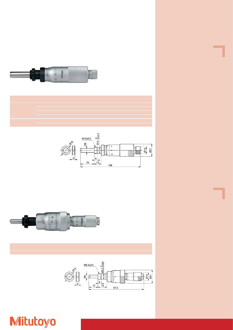
90
110–102
110–101
Series 110
• Micrometer heads with non-rotating spindle, especially suited for fine adjustments.
Micrometer Heads
Measuring range
No.
Graduation
Error limit
Mass
Comments
mm
mm
mm
g
0–1
110–105
0,001
0,003
150
110–107
0,001
0,003
150
Spherical measuring surface
110–106
0,0001
0,003
150
110–108
0,0001
0,003
150
Spherical measuring surface
0–2,5
110–101
0,001
0,005
150
110–102
0,0001
0,005
150
Dimensions of all devices see page 88 and 89
110–502
Series 110
• Micrometer heads with non-rotating spindle and double thimble scale.
• Graduation 0,5 mm, especially suited for fine adjustments.
Measuring range
No.
Graduation
Error limit
Mass
Comments
mm
mm
mm
g
0–13
110–502
0,0005
0,003
100
Spherical measuring surface
Dimensions of all devices see page 88 and 89
110–502
Specifications
Accuracy:
Factory specification
Stem:
with adjusting nut
Measuring surfaces: carbide-tipped
Specifications
Accuracy:
Factory specification
Fine adjustment: 0,2 mm
Stem:
with adjusting nut
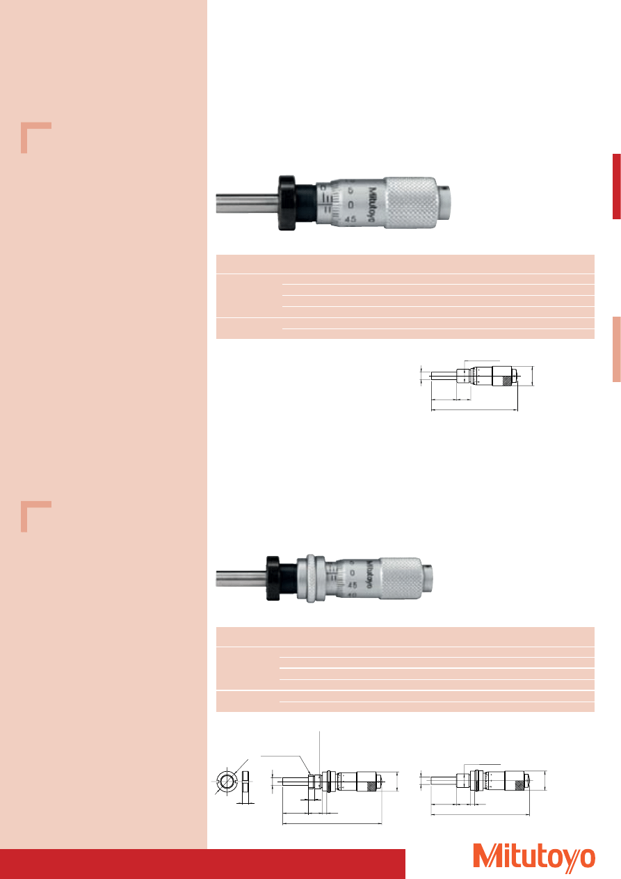
91
Specifications
Accuracy: Factory specification
Stem:
with / without adjustment nut
Specifications
Accuracy: Factory specification
Stem:
with / without adjustment nut
58.5
Ø5
9.5
17.5
Ø9.5
0
-0.009
Ø13
148–104
Series 148
• Micrometer heads especially suited for fine adjustments.
Micrometer Heads
Dimensions of all devices see page 88 and 89
67
Ø5
3
9.5
17.5
Ø9.5
0
-0.009
Ø13
Series 148
• Micrometer heads with lock, especially suited for fine adjustments.
Measuring range
No.
Graduation
Error limit
Mass
Comments
mm
mm
mm
g
0–13
148–120
0,01
0,002
40
with adjusting nut
148–121
0,01
0,002
40
without adjusting nut
148–803
0,01
0,002
50
spherical measuring surface, without adjusting nut
148–804
0,01
0,002
50
spherical measuring surface, with adjusting nut
13–0
148–823
0,01
0,002
50
reversable scale, without adjusting nut
148–824
0,01
0,002
50
reversable scale, with adjusting nut
Dimensions of all devices see page 88 and 89
148–121
Measuring range
No.
Graduation
Error limit
Mass
Comments
mm
mm
mm
g
0–13
148–103
0,01
0,002
35
with adjusting nut
148–104
0,01
0,002
35
without adjusting nut
148–801
0,01
0,002
35
spherical measuring surface, without adjusting nut
148–802
0,01
0,002
35
spherical measuring surface, with adjusting nut
13–0
148–821
0,01
0,002
35
reversable scale, without adjusting nut
148–822
0,01
0,002
35
reversable scale, with adjusting nut
67
Ø5
3
9.5
17.5
Ø9.5
0
-0.009
4
M9.5 x 0.5
Ø13
Ø14
4
148–120
148–120
148–103
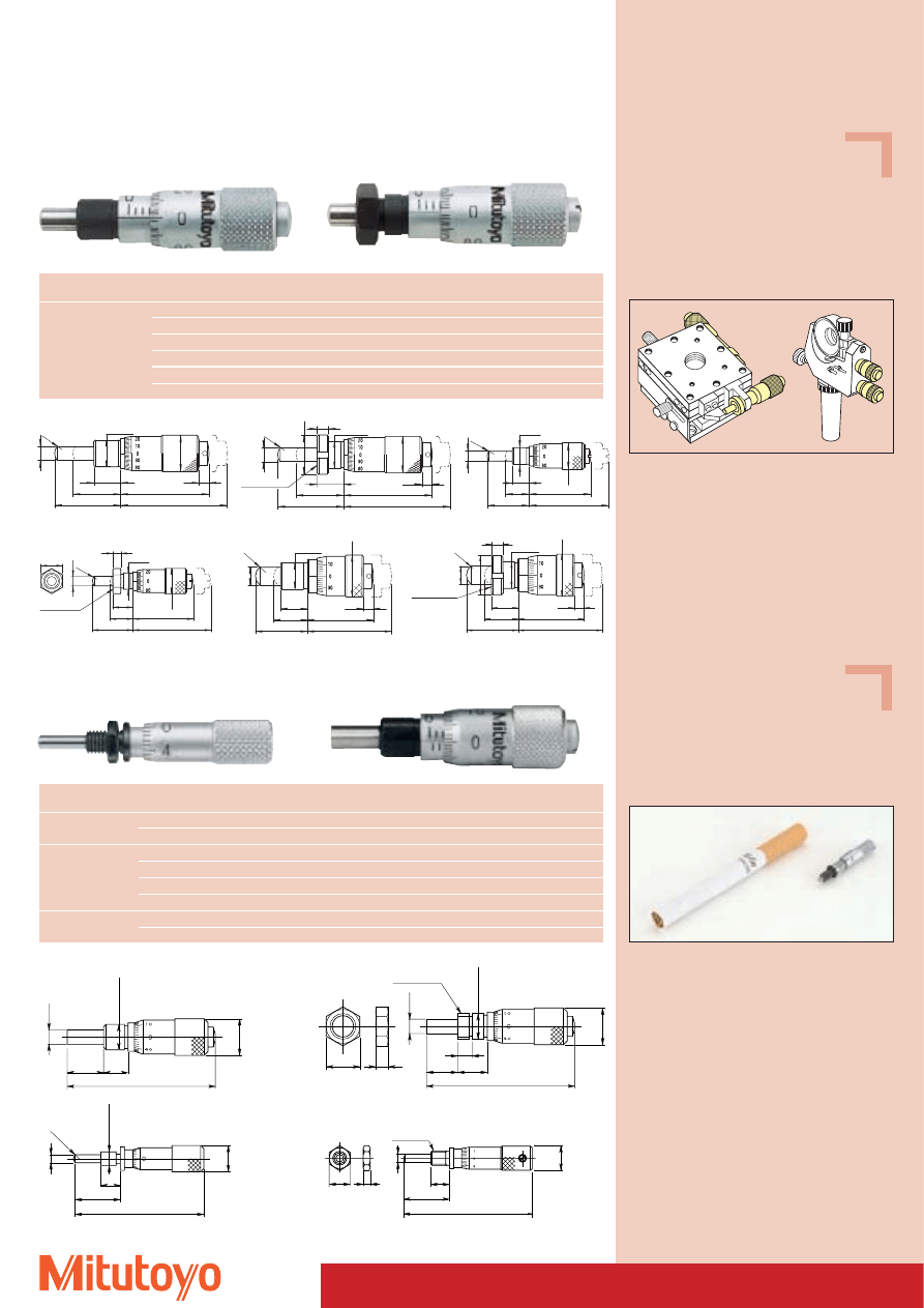
92
Specifications
Accuracy:
Factory specification
Stem:
with / without adjustment nut
Pitch:
0,1 mm
Measuring surfaces: carbide-tipped
37
Ø3.5
7.5
Ø9.3
Ø6
0
-0.008
7.5
4
M6x0.5
8
3
148–242
148–243
148–203
Ø5
Ø 9.5
Ø1
3
3.5
9.5
23.5
31.5
(38)
(17)
SR4
-0.009
0
Series 148
Small size micrometer heads with extremely small pitch 0.1 mm
Micrometer Heads
Dimensions of all devices see page 88 and 89
32
11.5
5
M3.5x0.5
5.5
1.8
Ø2
Ø6
148–201
148–216
37
Ø3.5
9
Ø9.3
Ø6
0
-0.008
6
SR1.5
32
Ø2
11.5
5
Ø3.5
0
-0.010
Ø6
148–215
Measuring range
No.
Graduation
Error limit
Mass
Comments
mm
mm
mm
g
0–5
148–215
0,02
0,005
4
spherical measuring surface, without adjusting nut
148–216
0,02
0,005
5
spherical measuring surface, with adjusting nut
0–6,5
148–201
0,01
0,002
10
without adjusting nut
148–203
0,01
0,002
10
with adjusting nut
148–205
0,01
0,002
10
spherical measuring surface, without adjusting nut
148–207
0,01
0,002
10
spherical measuring surface, with adjusting nut
6,5–0
148–209
0,01
0,002
10
reversable scale, without adjusting nut
148–211
0,01
0,002
10
reversable scale, with adjusting nut
Measuring range
No.
Graduation
Error limit
Mass
Comments
mm
mm
mm
g
0–6,5
148–142
0,002
2
31
9,5 mm shaft
148–143
0,002
2
34
9,5 mm shaft and adjusting nut
148–242
0,002
5
10
6 mm shaft
148–243
0,002
5
10
6 mm shaft and adjusting nut
148–342
0,002
2
29
9,5 mm shaft
148–343
0,002
2
31
9,5 mm shaft and adjusting nut
Specifications
Accuracy: Factory specification
Stem:
with / without adjustment nut
148–216
Series 148
Small size micrometer heads
148–142
-0.09
0
9.5
4
Ø1
4
Ø5
31.5
23.5
(17)
3.5
Ø1
3
Ø 9.5
SR4
(38)
M9.5 x 0.5
148–143
Ø
3.5
(8.5)
(28.4)
21.9
15
6
Ø9
.3
Ø 6
SR3
-0.008
0
148–242
Ø
3.5
3
(28.4)
21.9
(8.5)
15
M6 x 0.5
7.5
Ø
9.3
Ø 6
8
SR3
-0.008
0
148–243
(30)
(12)
23.5
3.5
18.5
Ø
6.35
Ø 9.5
Ø1
5
9.5
SR4
-0.009
0
148–342
4
(30)
(12)
23.5
Ø1
5
Ø 9.5
Ø1
4
18.5
M9.5 x 0.5
9.5
3.5
Ø
6.35
SR4
-0.009
0
148–343
148–201
Ideal for extremely fine positioning due to the
extremely fine pitch of 0.1 mm
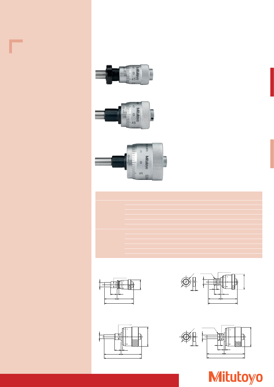
93
Specifications
Accuracy: Factory specification
Stem:
with / without adjustment nut
Ø15
Ø6.35
42
18.5
23.5
2
9.5
Ø9.5
0
-0.009
148–302
148–301
Ø29
Ø6.35
55
25
30
9.5
2
Ø9.5
0
-0.009
148–311
Series 148
• Small size micrometer with large scale thimble.
Micrometer Heads
Dimensions of all devices see page 88 and 89
42
18.5
23.5
2
9.5
Ø14
4
Ø6.35
Ø20
M9.5x0.5
4
Ø9.5
0
-0.009
148–303
148–304
Ø29
Ø6.35
55
25
30
9.5
2
M9.5x0.5
Ø14
4
4
Ø9.5
0
-0.009
148–312
Measuring range
No.
Graduation
Error limit
Thimble Ø
Mass
Comments
mm
mm
mm
mm
g
0–6,5
148–301
0,01
0,005
15
26
without adjusting nut
148–302
0,01
0,005
15
26
with adjusting nut
148–303
0,01
0,002
20
39
without adjusting nut
148–304
0,01
0,002
20
39
with adjusting nut
148–305
0,01
0,002
29
71
without adjusting nut
148–306
0,01
0,002
29
71
with adjusting nut
0–13
148–307
0,01
0,002
15
35
without adjusting nut
148–308
0,01
0,002
15
35
with adjusting nut
148–309
0,01
0,002
20
55
without adjusting nut
148–310
0,01
0,002
20
55
with adjusting nut
148–311
0,01
0,002
29
103
without adjusting nut
148–312
0,01
0,002
29
103
with adjusting nut
148–311
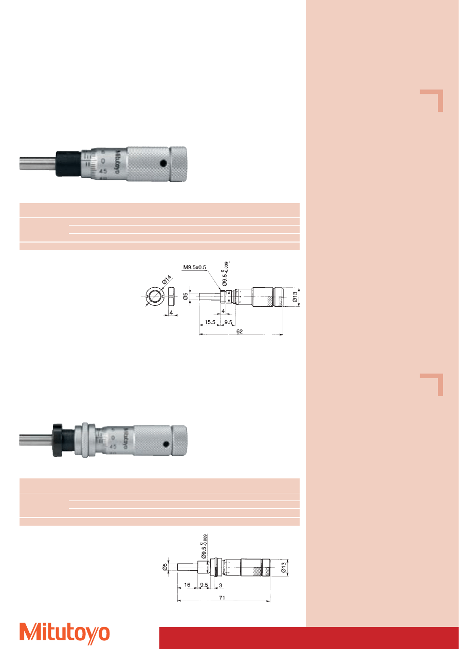
Specifications
Accuracy: Factory specification
Stem:
with / without adjustment nut
94
Specifications
Accuracy: Factory specification
Stem:
with / without adjustment nut
Micrometer Heads
148–503
148–508
Series 148
• Micrometer heads with variable zero-setting.
• By loosening the (headless) screw on the thimble the origin may be set to random positions.
Dimensions of all devices see page 88 and 89
148–504
Series 148
• Micrometer heads with variable zero-setting.
• By loosening the (headless) screw on the thimble the origin may be set to random positions..
Measuring range
No.
Graduation
Error limit
Mass
Comments
mm
mm
mm
g
0–13
148–504
0,01
0,002
40
with adjusting nut
148–506
0,01
0,002
40
without adjusting nut
148–854
0,01
0,002
40
spherical measuring surface, with adjusting nut
13–0
148–864
0,01
0,002
40
reversable scale, with adjusting nut
Dimensions of all devices see page 88 and 89
148–506
Measuring range
No.
Graduation
Error limit
Mass
Comments
mm
mm
mm
g
0–13
148–503
0,01
0,002
40
without adjusting nut
148–508
0,01
0,002
40
with adjusting nut
148–853
0,01
0,002
40
spherical measuring surface, without adjusting nut
13–0
148–863
0,01
0,002
40
reversable scale, without adjusting nut
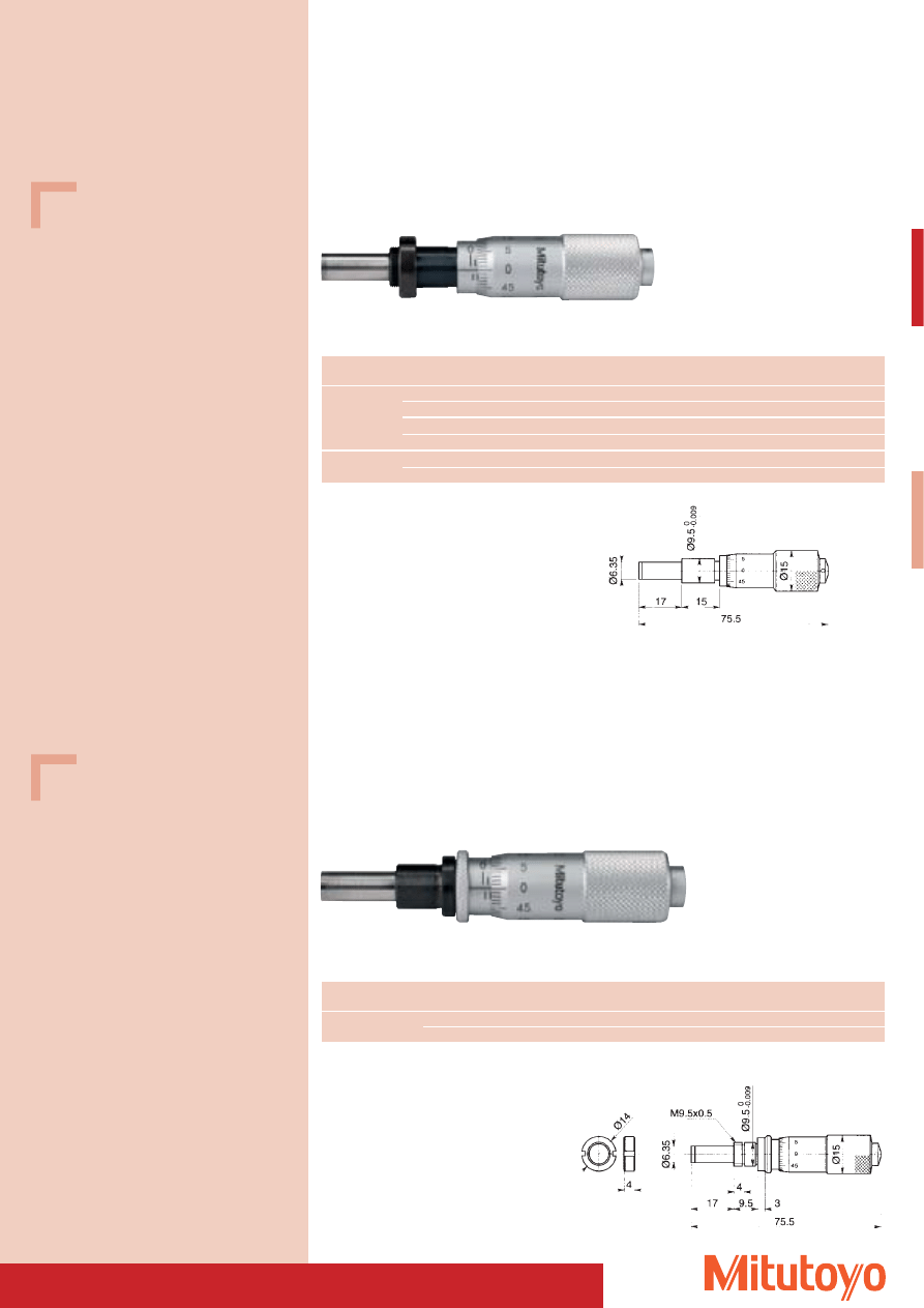
95
Specifications
Accuracy:
Factory specification
Stem:
with / without adjustment nut
Measuring surfaces: carbide-tipped
Specifications
Accuracy:
Factory specification
Stem:
with / without adjustment nut
Measuring surfaces: carbide-tipped
149–131
149–132
Series 149
Micrometer Heads
Dimensions of all devices see page 88 and 89
149–183
Series 149
• Micrometer head with clamping device.
Measuring range
No.
Graduation
Error limit
Mass
Comments
mm
mm
mm
g
0–15
149–183
0,01
0,002
60
without adjusting nut
149–184
0,01
0,002
60
with adjusting nut
Dimensions of all devices see page 88 and 89
149–184
Measuring range
No.
Graduation
Error limit
Mass
Comments
mm
mm
mm
g
0–15
149–131
0,01
0,002
55
with adjusting nut
149–132
0,01
0,002
55
without adjusting nut
149–801
0,01
0,002
55
spherical measuring surface, without adjusting nut
149–802
0,01
0,002
55
spherical measuring surface, with adjusting nut
15–0
149–821
0,01
0,002
55
reversable scale, without adjusting nut
149–822
0,01
0,002
55
reversable scale, with adjusting nut
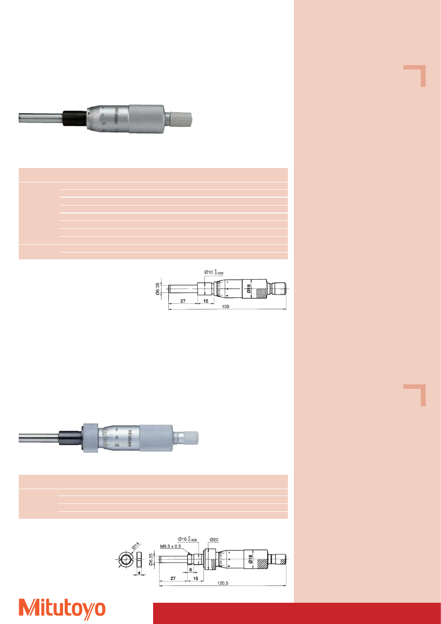
Specifications
Accuracy:
Factory specification
Stem:
with / without adjustment nut
Measuring surfaces: carbide-tipped
Specifications
Accuracy:
Factory specification
Stem:
with / without adjustment nut
Measuring surfaces: carbide-tipped
96
150–192
150–192
Series 150
Micrometer Heads
Dimensions of all devices see page 88 and 89
150–209
Series 150
• Micrometer head with clamping device.
Measuring range
No.
Graduation
Error limit
Mass
Comments
mm
mm
mm
g
0–25
150–209
0,01
0,002
125
without adjusting nut, with ratchet
150–210
0,01
0,002
125
with adjusting nut, with ratchet
150–211
0,01
0,002
115
without ratchet, without adjusting nut
150–212
0,01
0,002
115
without ratchet, with adjusting nut
Dimensions of all devices see page 88 and 89
150–210
Measuring range
No.
Graduation
Error limit
Mass
Comments
mm
mm
mm
g
0–25
150–189
0,001
0,002
90
with adjusting nut, with ratchet
150–190
0,001
0,002
90
without adjusting nut, with ratchet
150–191
0,01
0,002
90
with adjusting nut, with ratchet
150–192
0,01
0,002
90
without adjusting nut, with ratchet
150–195
0,01
0,002
90
without ratchet, with adjusting nut
150–196
0,01
0,002
90
without ratchet, without adjusting nut
150–801
0,01
0,002
90
spherical measuring surface, without adjusting nut, with ratchet
150–802
0,01
0,002
90
spherical measuring surface, with adjusting nut, with ratchet
25–0
150–821
0,01
0,002
90
reversable scale, without adjusting nut, with ratchet
150–822
0,01
0,002
90
reversable scale, with adjusting nut, with ratchet
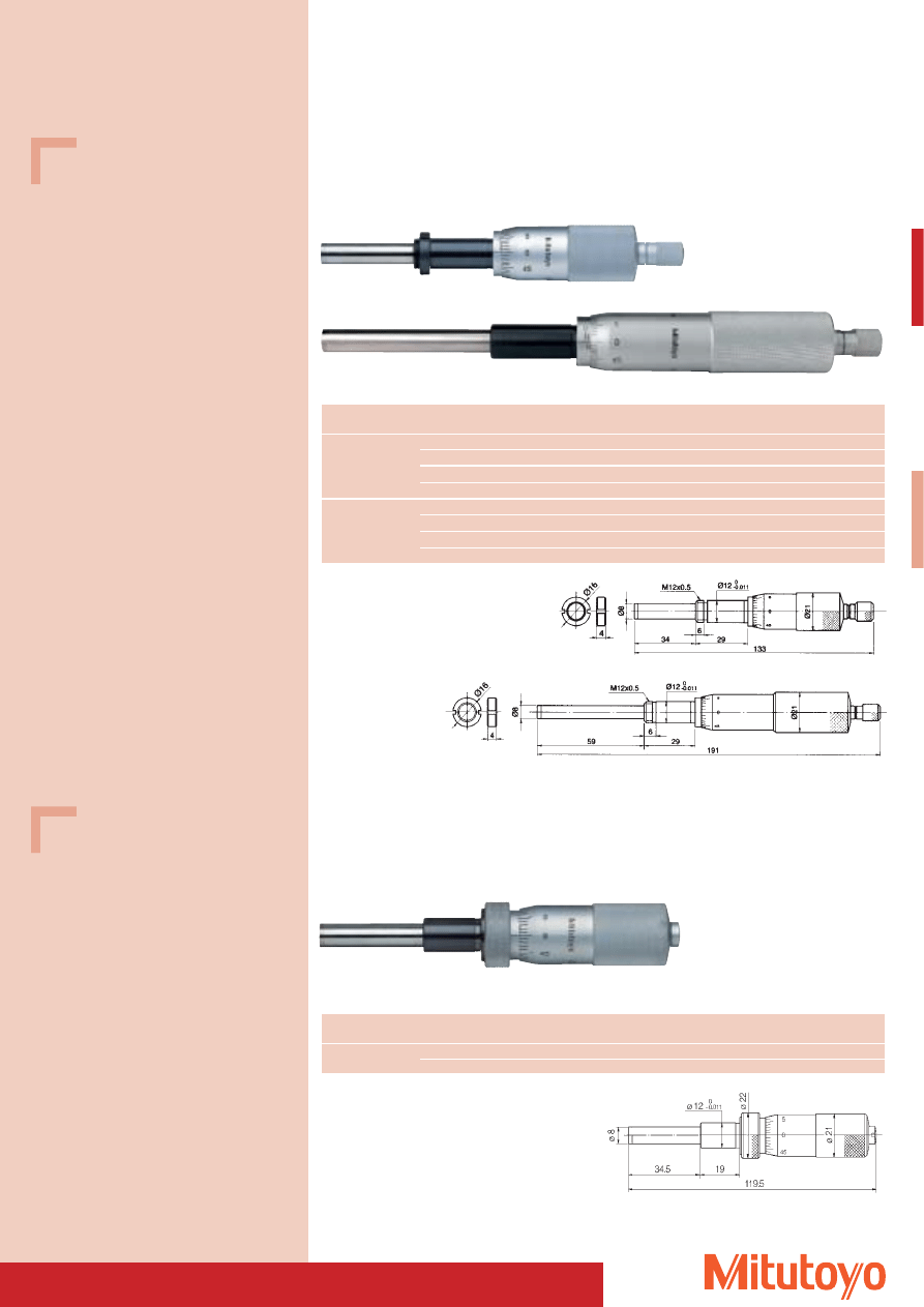
97
Specifications
Accuracy:
Factory specification
Stem:
with / without adjustment nut
Measuring surfaces: carbide-tipped
Specifications
Accuracy:
Factory specification
Stem:
with / without adjustment nut
Measuring surfaces: carbide-tipped
151–225
Series 151
• Micrometer head with clamping device and 8 mm spindle diameter.
• Heavy duty.
Measuring range
No.
Graduation
Error limit
Mass
Comments
mm
mm
mm
g
0–25
151–225
0,01
0,002
165
without adjusting nut, without ratchet
151–226
0,01
0,002
165
with adjusting nut, without ratchet
Dimensions of all devices see page 88 and 89
151–225
151–223
151–223
Series 151
• Micrometer head with/without ratchet and 8 mm spindle diameter.
• Heavy duty.
Micrometer Heads
Dimensions of all devices see page 88 and 89
151–256
151–255
Measuring range
No.
Graduation
Error limit
Mass
Comments
mm
mm
mm
g
0–25
151–221
0,001
0,002
160
with adjusting nut, with ratchet
151–222
0,001
0,002
150
without adjusting nut, with ratchet
151–223
0,01
0,002
160
with adjusting nut, with ratchet
151–224
0,01
0,002
150
without adjusting nut, with ratchet
0–50
151–255
0,01
0,004
250
with adjusting nut, with ratchet
151–256
0,01
0,004
240
without adjusting nut, with ratchet
151–259
0,01
0,004
250
without ratchet, with adjusting nut
151–260
0,01
0,004
240
without ratchet, without adjusting nut
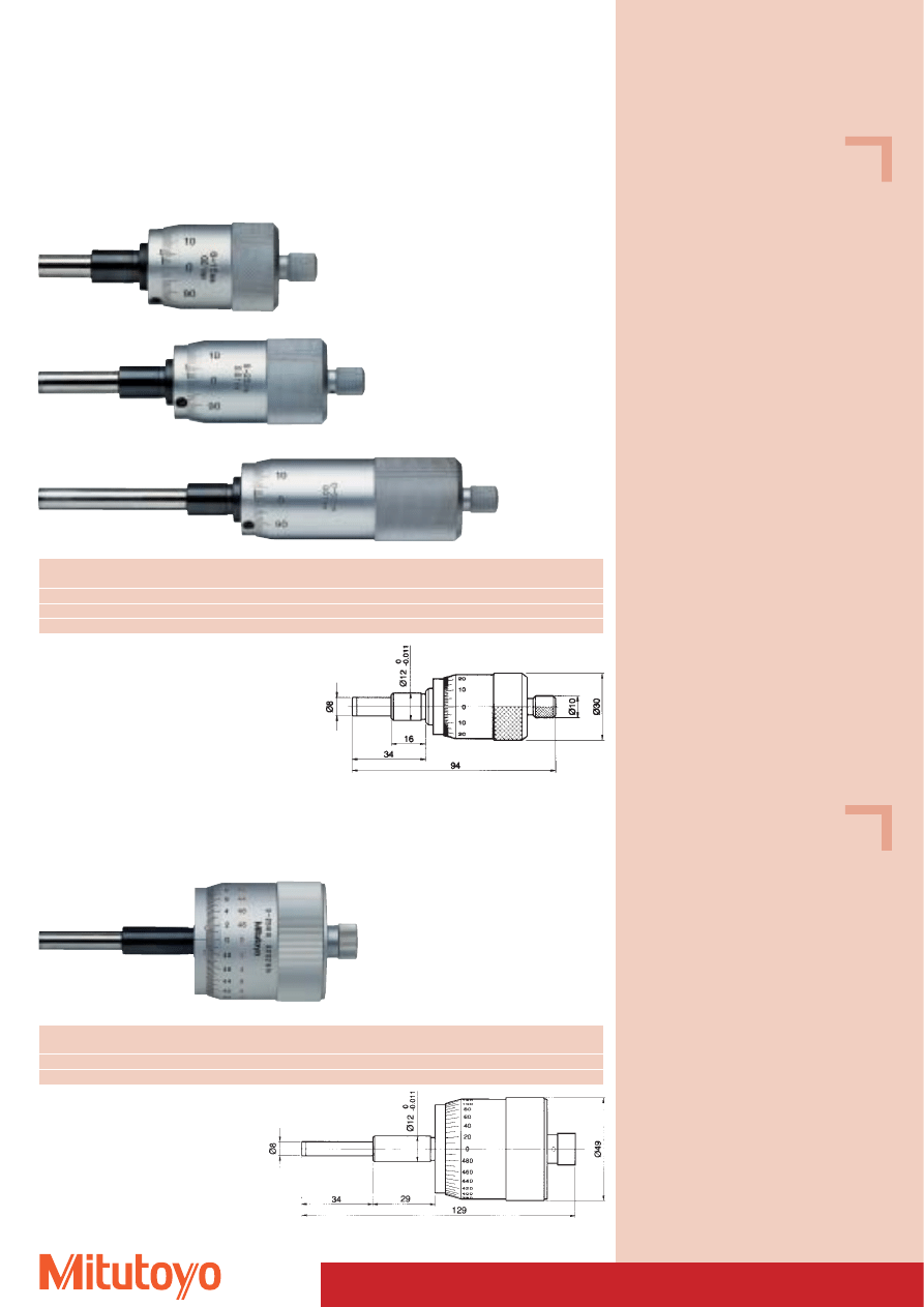
Specifications
Accuracy:
Factory specification
Stem:
without adjusting nut
Measuring surfaces: carbide-tipped
Specifications
Accuracy:
Factory specification
Stem:
without adjusting nut
Measuring surfaces: carbide-tipped
98
152–101
Series 152
• Micrometer head with 1 mm spindle pitch to avoid errors in reading.
• Measurement value can be read from the 100 step graduation thimble without calculation of
1
/
2
mm
values.
Micrometer Heads
Dimensions of all devices see page 88 and 89
152–102
152–101
Measuring range
No.
Graduation
Error limit
Mass
mm
mm
mm
g
0–15
152–101
0,01
0,002
205
0–25
152–102
0,01
0,002
230
0–50
152–103
0,01
0,004
355
152–103
Series 152
• Micrometer head with large thimble and bi-direction reading.
• Black and red scaling for both directions.
Measuring range
No.
Graduation
Error limit
Mass
mm
mm
mm
g
0–25–0
152–348
0,002
0,002
310
0–50–0
152–380
0,002
0,004
460
Dimensions of all devices see page 88 and 89
152–348
152–348
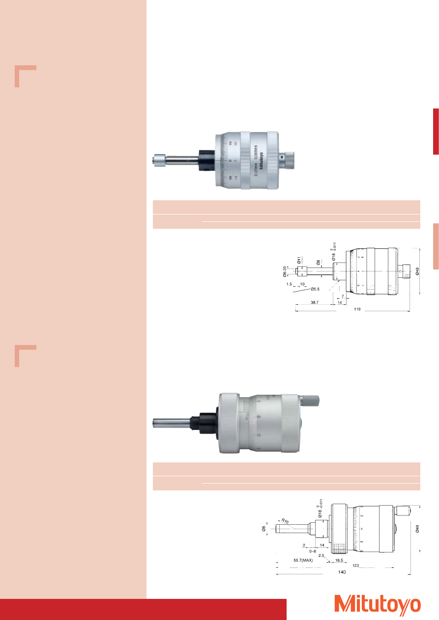
99
Specifications
Accuracy: Factory specification
Specifications
Accuracy:
Factory specification
Measuring surfaces: carbide-tipped
Zero-setting can be performed directly using
the sleeve.
Micrometer Heads For x/y travel
Series 152
• Micrometer heads with rotating spindle, non-rotating measuring surface and bi-directional reading.
• Reading in both directions of graduation engraved in black and red.
• The measurement values can be read directly from the 100 step graduation without having to add
the
1
/
2
mm values.
Dimensions of all devices see page 88 and 89
152–389
152–390
Measuring range
No.
Graduation
Error limit
Mass
Comments
mm
mm
mm
g
0–25–0
152–389
0,005
0,002
270
for Y-axis
152–390
0,005
0,002
270
for X-axis
Measuring range
No.
Graduation
Error limit
Mass
Comments
mm
mm
mm
g
0–25–0
152–401
0,001
0,002
460
for Y-axis
152–402
0,001
0,002
460
for X-axis
Dimensions of all devices see page 88 and 89
152–402
Series 152
• Micrometer head with extra large thimble Floating ZERO adjustment.
• The measurement values can be read directly from the 100 step graduation without having to add
the
1
/
2
mm values.
152–402
Bore
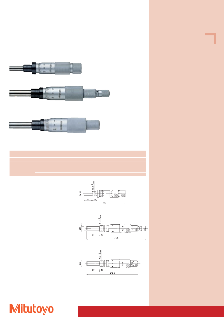
Specifications
Accuracy:
Factory specification
Measuring surfaces: carbide-tipped
100
153–101
Series 153
• Micrometer head with non-rotating spindle.
Micrometer Heads
Dimensions of all devices see page 88 and 89
153–201
153–101
153–201 + 153–202
153–203 + 153–204
Measuring range
No.
Graduation
Error limit
Mass
Comments
mm
mm
mm
g
0–15
153–101
0,01
0,003
70
0–25
153–201
0,01
0,003
122
with ratchet
153–202
0,001
0,003
122
with ratchet
153–203
0,01
0,003
117
153–204
0,001
0,003
117
153–204
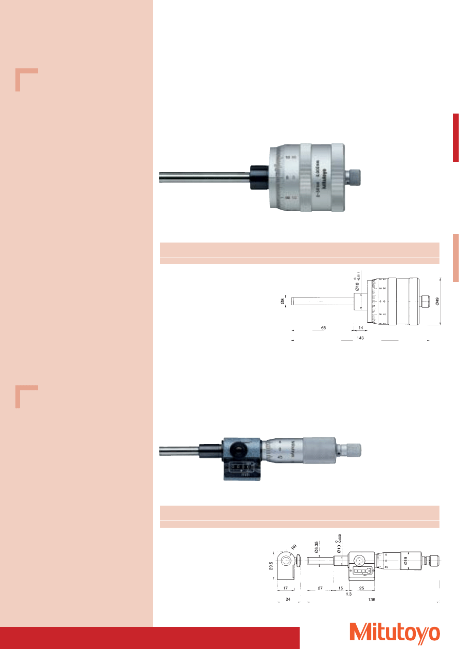
101
Specifications
Accuracy:
Factory specification
Measuring surfaces: carbide-tipped
Specifications
Accuracy:
Factory specification
Measuring surfaces: carbide-tipped
Micrometer Heads
Series 197
• Micrometer head with double-threaded non-rotating spindle and 1 mm spindle pitch.
• The measurement values can be read directly from the 100 step gradutation without having to add
the
1
/
2
mm values.
• The scale can be reset by turning the scale shell.
Dimensions of all devices see page 88 and 89
197–101
197–101
Measuring range
No.
Graduation
Error limit
Mass
mm
mm
mm
g
0–50
197–101
0,005
0,005
360
Dimensions of all devices see page 88 and 89
250–301
250–301
Measuring range
No.
Graduation
Error limit
Mass
mm
mm
mm
g
0–25
250–301
0,01
0,002
165
Series 250
• Micrometer with counter and ratchet.
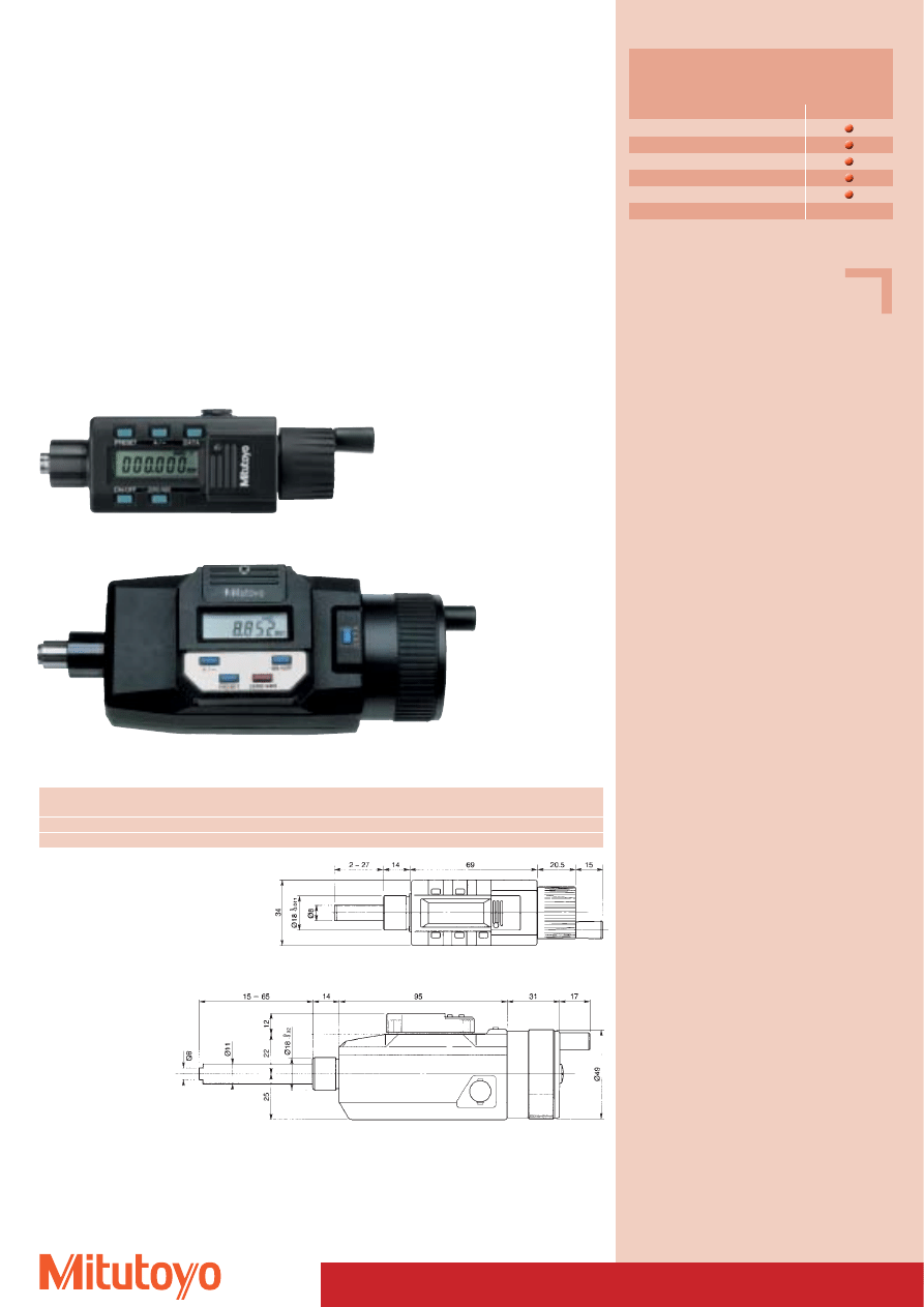
Specifications
Accuracy:
Factory specification
Measuring surfaces: carbide-tipped
Including battery 164–171 (1 x)
and 164–161 (2 x)
Optional accessories
No. 937387
Signal cable (1 m)
No. 965013
Signal cable (2 m)
Consumable Spares
No. 938882
Battery SR-44
102
164–171
164–161
Series 164
• Display and operating unit may be rotated by 330° for convenience (164–161 only)
• For integration into machinery and measuring facilities.
• Digital micrometer head with non-rotating spindle.
• Direct reading of 0,001 mm from clear digital display.
• Accurate and error free measurement.
“DIGIMATIC” Micrometer Heads
164–171
164–161
Measuring range
No.
Resolution
Error limit
Mass
mm
mm
mm
g
0–25
164–171
0,001
0,002
160
0–50
164–161
0,001
0,003
500
Functions
Series 164
ON/OFF
PRESET
+/– Revers measuring direction
ZERO/ABS
Data output
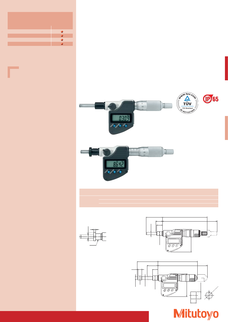
103
Specifications
Protection class: IP-65
Accuracy:
Factory specification
Including battery, key,
bushing Ø 18 mm (350–261, 350–271)
Optional accessories
No. 05CZA662
Signal cable (1 m)
No. 05CZA663
Signal cable (2 m)
Consumable Spares
No. 938882
Battery SR-44
Series 350
• For integration into machinery and measuring facilities.
• Digital micrometer head.
• Direct reading of clearly displayed 0,001 mm step measurement values.
• Accurate and error-free measuring.
“DIGIMATIC” Micrometer Heads
-0.01
1
Ø 12
0
5
0
45
10
(1.5)
(101)
52.7
14
Ø 6.35
Ø 6.35
(126)
(27.7)
(58)
Ø 11
Ø 18
350–261
5
0
45
15
42
Ø
6.35
(17)
(139.5)
114.5
(58)
0
-0.009
Ø 18
-0.01
1
Ø 12
0
350–271
Measuring range
No.
Resolution
Error limit
Mass
Comments
mm
mm
mm
g
0–25
350–261
0,001
0,002
235
rotating spindle, non-rotating measuring surface
350–271
0,001
0,002
230
with ratchet, measuring surfaces carbide-tipped
350–272
0,001
0,002
230
with adjusting nut, with ratchet, measuring surfaces carbide-tipped
Functions
Series 350
PRESET
ZERO/ABS
HOLD
Data output
350–271
350–272
-0.011
14
0
Ø 18
Ø 12
+0.01 0
0
Ø
6.35
4
M12x1
350–261 / 350–272
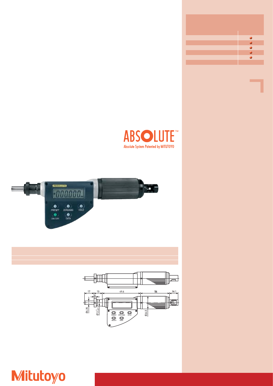
104
Specifications
Accuracy:
Factory specification
Resolution:
0,001 mm
Flatness:
울 0,3 mm
Measuring direction: horizontal *
Including box, 1 battery
* = a change in the direction of measurement
affects the measuring force; the guaranteed
tolerances only apply to horizontal measuring
(± 3 degrees).
Optional accessories
No. 937387
Signal cable (1 m)
No. 965013
Signal cable (2 m)
Consumable Spares
No. 938882
Battery SR-44
Functions
Series 227
ON/OFF
ORIGIN
DATA/HOLD
ZERO/ABS
Data output
227–241
A
Micrometer Heads
• Large figures, long battery life
The digital display is very easy to read with its 7.5 mm high figures. The battery life is approx. 3 years,
which corresponds approximately to 3 times the battery life of traditional digital external screw type
micrometers
• Precise measurement at high travel speed
The measuring system is an absolute linear scale with an numerical increment of 1 mm.
The absolute scale means that there can be no error displays due to excessive travel speed; the travel
speed is unlimited.
This micrometer has a newly-developed spindle mechanism that enables a spindle thrust of 10 mm/rev.
The thrust rate is therefore 20 x higher than with traditional micrometers.
• Exact measurements on sensitive surfaces
As the micrometer has a non-rotating spindle, measurements can also be carried out on sensitive
surfaces.
Series 227
Quick built-in micrometer with non-rotating spindle
and adjustable measuring force 0,5– 2,5 N
(at 227–241)
,
2,0–10,0 N
(at 227–242)
Measuring
No.
Adjustment range
Measuring force (N)
Error limits of measuring force
Error limit
Mass
range mm
for measuring force
Scale
(pre-adjusted measuring force)
mm
g
0–15
227–241
0,5– 2,5 N
0,5; 1,0; 1,5; 2,0; 2,5
0,1 + (adjusted measuring force / 10) N
2
260
0–15
227–242
2,0–10,0 N
2; 4; 6; 8; 10
0,4 + (adjusted measuring force / 10) N
2
260
TM
Patent numbers see page 464
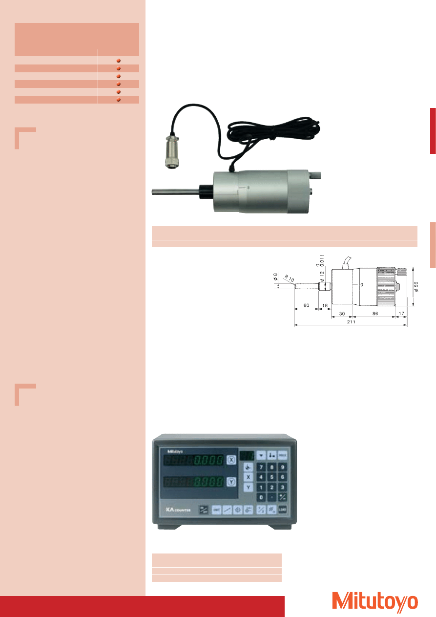
105
Specifications
Accuracy:
Factory specification
Measuring surfaces: carbide-tipped
Optional accessories
No. 09CAB231
Adapter for micrometer heads
164–122 (1 piece) for connection
to display unit KA counter
164–122
Electronic Micrometer Heads
164–122
Measuring range
No.
Resolution
Error limit
Mass
mm
mm
mm
g
0–50
164–122
0,001
0,002
760
Series 164
• With rotating spindle.
• Electronic micrometer head for integration into machinery and measuring facilities
in connection with KA counter of the serie 174.
Functions
Series 174
Zero-setting
Polarity switch
mm/inch switch
Preset/ZERO-setting
1/2 key
ABS/INC-coordinate switch
Specifications
Resolution:
0,005 mm, 0,001 mm
Display:
8 Digits, Denominator (–)
Operation temperature: 0 °C up to 45 °C
Optional accessories
No. 09CAB217
RS-232 C port
No. 011418
Foot switch for KA counter
for data output No. 09CAB217
No. 09CAB231
Adapter for micrometer heads
164–122 (1 piece)
Digital Display Unit for No. 164–122
Series 174
KA-Counter
User-friendly multifunctional display unit
No.
Axres Dimensions
(W x H x D)
Mass
mm
kg
174–173 D
2
260 x 167 x 80
1,1
174–175 D
3
260 x 167 x 80
1,2
174–173 D
Wyszukiwarka
Podobne podstrony:
narzędzia suwmiarkowe Mitutoyo
3 SUWMIARKOWE I MIKROMETRYCZNE NARZĘDZIA POMIAROWE(2)
Narzedzia wspomagajace zarzadzanie projektem
Język jako narzędzie paradoksy
narzedzia
Narzędzia chirurgiczne i ich rodzaje
sprzet lab mikromanometry
Podstawowe stale konstrukcyjne i narzędziowe
MRIT Materiały narzędziowe
Komputer przenośny nowoczesne narzędzie
63 MT 09 Przybornik narzedziowy
Narzędzia tokarskie
12 Narzedzia promocji miejscowo Nieznany (2)
więcej podobnych podstron