
4B
General
Injection system type:
C16 NZ, C16 NZ2, X16 SZ and C18 NZ . . . . . . . . . . . . . . . . . . . . . . .
Multec Central Fuel Injection
20 NE, C20 NE and 20 SEH, (up to 1990) . . . . . . . . . . . . . . . . . . . . .
Motronic M4.1
20 NE, C20 NE and 20 SEH, (from 1990) . . . . . . . . . . . . . . . . . . . . . .
Motronic M1.5
20 XEJ and C20 XE, (up to 1993) . . . . . . . . . . . . . . . . . . . . . . . . . . . .
Motronic M2.5
C20 XE (from 1993) . . . . . . . . . . . . . . . . . . . . . . . . . . . . . . . . . . . . . . .
Motronic M2.8
X20 XEV . . . . . . . . . . . . . . . . . . . . . . . . . . . . . . . . . . . . . . . . . . . . . . .
Simtec 56.1
Fuel tank capacity:
All models . . . . . . . . . . . . . . . . . . . . . . . . . . . . . . . . . . . . . . . . . . . . . .
63.0 ± 2 litres
Fuel octane rating *
Leaded . . . . . . . . . . . . . . . . . . . . . . . . . . . . . . . . . . . . . . . . . . . . . . . .
98 RON (4-star)
Unleaded (refer to Chapter 5) * . . . . . . . . . . . . . . . . . . . . . . . . . . . . . .
95 RON (Premium)
* Note: Models fitted with a catalytic converter (engine code prefixed by ‘C’ or ‘X’), must only be operated on unleaded fuel.
Idle settings
Idle speed:
C16 NZ and X16 SZ . . . . . . . . . . . . . . . . . . . . . . . . . . . . . . . . . . . . . .
850 ± 80 rpm
C16 NZ2 . . . . . . . . . . . . . . . . . . . . . . . . . . . . . . . . . . . . . . . . . . . . . . .
880 ± 80 rpm
C18 NZ
Manual transmission models . . . . . . . . . . . . . . . . . . . . . . . . . . . . .
880 ± 80 rpm
Automatic transmission models . . . . . . . . . . . . . . . . . . . . . . . . . . .
830 ± 80 rpm
20 NE, C20 NE and 20 SEH . . . . . . . . . . . . . . . . . . . . . . . . . . . . . . . .
800 ± 80 rpm
20 XEJ and C20 XE . . . . . . . . . . . . . . . . . . . . . . . . . . . . . . . . . . . . . . .
940 ± 80 rpm
X20 XEV . . . . . . . . . . . . . . . . . . . . . . . . . . . . . . . . . . . . . . . . . . . . . . .
850 ± 160 rpm
Note: Idle speed adjustment is not possible on these models, for information only
Chapter 4 Part B:
Fuel and exhaust systems - fuel injection models
Air box - removal and refitting . . . . . . . . . . . . . . . . . . . . . . . . . . . . . . .5
Air cleaner - removal and refitting . . . . . . . . . . . . . . . . . . . . . . . . . . . .4
Air filter element - renewal . . . . . . . . . . . . . . . . . . . . . . . .See Chapter 1
Airflow meter (if fitted) - removal and refitting . . . . . . . . . . . . . . . . . .25
Air mass meter (if fitted) - removal and refitting . . . . . . . . . . . . . . . . .26
Air temperature sensor (later models) - removal and refitting . . . . . . .7
Air temperature control - description and testing . . . . . . . . . . . . . . . .6
Depressurising the fuel system - general . . . . . . . . . . . . . . . . . . . . . . .8
Electronic Control Unit (ECU) - removal and refitting . . . . . . . . . . . . .35
Fuel filter (‘In-tank’ fuel pump models) - removal and refitting . . . . . .10
Fuel filter (‘Out-of-tank’ fuel pump models) - removal and refitting . . .9
Fuel flow damper - removal and refitting . . . . . . . . . . . . . . . . . . . . . .18
Fuel injection system - precautions . . . . . . . . . . . . . . . . . . . . . . . . . . .2
Fuel injector (Multec system) - removal and refitting . . . . . . . . . . . . .29
Fuel injector (Multec system) - testing . . . . . . . . . . . . . . . . . . . . . . . .30
Fuel injectors (except Multec system) - removal and refitting . . . . . .28
Fuel pressure regulator - removal and refitting . . . . . . . . . . . . . . . . .21
Fuel pump - testing . . . . . . . . . . . . . . . . . . . . . . . . . . . . . . . . . . . . . .11
Fuel pump (‘In-tank’ fuel pump models) - removal and refitting . . . .13
Fuel pump (‘Out-of-tank’ fuel pump models) - removal and refitting .12
Fuel pump relay - renewal . . . . . . . . . . . . . . . . . . . . . . . . . . . . . . . . .14
Fuel tank - removal and refitting . . . . . . . . . . . . . . . . . . . . . . . . . . . . .16
Fuel tank filler pipe - removal and refitting . . . . . . . . . . . . . . . . . . . . .15
Fuel tank sender unit - removal and refitting . . . . . . . . . . . . . . . . . . .17
General description . . . . . . . . . . . . . . . . . . . . . . . . . . . . . . . . . . . . . . .1
Hot film mass airflow meter - removal and refitting . . . . . . . . . . . . . .27
Idle air control stepper motor - removal and refitting . . . . . . . . . . . . .33
Idle mixture - checking and adjustment . . . . . . . . . . . . . . . . . . . . . . .20
Idle speed adjuster - removal and refitting . . . . . . . . . . . . . . . . . . . . .22
Inlet manifold (DOHC models) - removal and refitting . . . . . . . . . . . .40
Inlet manifold (SOHC with Multec) - removal and refitting . . . . . . . . .39
Inlet manifold (SOHC without Multec) - removal and refitting . . . . . .38
Knock sensor and module (X16 SZ models) - removal and refitting .36
Knock sensor (Simtec system) - removal and refitting . . . . . . . . . . . .37
System testing - general . . . . . . . . . . . . . . . . . . . . . . . . . . . . . . . . . . . .3
Throttle body (except Multec system) - removal and refitting . . . . . .31
Throttle body (Multec system) - removal and refitting . . . . . . . . . . . .32
Throttle cable - removal, refitting and adjustment . . . . . . . . . . . . . . .19
Throttle pedal - removal and refitting . . . . . . . . . . . . . .See Chapter 4A
Throttle position sensor - removal and refitting . . . . . . . . . . . . . . . . .23
Throttle potentiometer - removal and refitting . . . . . . . . . . . . . . . . . .34
Throttle valve potentiometer - removal and refitting . . . . . . . . . . . . .24
4B•1
Specifications
Contents
Easy, suitable for
novice with little
experience
Fairly easy, suitable
for beginner with
some experience
Fairly difficult,
suitable for competent
DIY mechanic
Difficult, suitable for
experienced DIY
mechanic
Very difficult,
suitable for expert DIY
or professional
Degrees of difficulty
5
4
3
2
1

Idle settings (continued)
Idle mixture (CO content):
20 NE and 20 SEH . . . . . . . . . . . . . . . . . . . . . . . . . . . . . . . . . . . . . . .
1.0 max.
20 XEJ . . . . . . . . . . . . . . . . . . . . . . . . . . . . . . . . . . . . . . . . . . . . . . . . .
0.7 to 1.2%
All other models . . . . . . . . . . . . . . . . . . . . . . . . . . . . . . . . . . . . . . . . .
0.3 % (at 2800 to 3200 rpm)
Fuel Pressure (regulator vacuum hose connected)
Multec . . . . . . . . . . . . . . . . . . . . . . . . . . . . . . . . . . . . . . . . . . . . . . . . . . .
0.76 bar
Motronic 4.1:
Feed . . . . . . . . . . . . . . . . . . . . . . . . . . . . . . . . . . . . . . . . . . . . . . . . . .
2.3 to 2.7 bar
Return . . . . . . . . . . . . . . . . . . . . . . . . . . . . . . . . . . . . . . . . . . . . . . . . .
0.3 to 1.5 bar
Motronic 1.5:
Feed . . . . . . . . . . . . . . . . . . . . . . . . . . . . . . . . . . . . . . . . . . . . . . . . . .
1.8 to 2.2 bar
Return . . . . . . . . . . . . . . . . . . . . . . . . . . . . . . . . . . . . . . . . . . . . . . . . .
0.3 to 1.5 bar
Motronic 2.5 . . . . . . . . . . . . . . . . . . . . . . . . . . . . . . . . . . . . . . . . . . . . . .
2.0 to 2.2 bar
Motronic 2.8 . . . . . . . . . . . . . . . . . . . . . . . . . . . . . . . . . . . . . . . . . . . . . .
2.2 to 2.7 bar
Simtec 56.1 . . . . . . . . . . . . . . . . . . . . . . . . . . . . . . . . . . . . . . . . . . . . . . .
not available
Torque wrench settings
Nm
lbf ft
All specifications as for carburettor models except for the following:
Bracket, tank vent valve to coolant flange . . . . . . . . . . . . . . . . . . . . . . .
8
6
Fuel distributor pipe to inlet manifold . . . . . . . . . . . . . . . . . . . . . . . . . . .
8
6
Fuel flow damper . . . . . . . . . . . . . . . . . . . . . . . . . . . . . . . . . . . . . . . . . .
20
15
Fuel injector retainer . . . . . . . . . . . . . . . . . . . . . . . . . . . . . . . . . . . . . . . .
3
2
Fuel pressure regulator . . . . . . . . . . . . . . . . . . . . . . . . . . . . . . . . . . . . . .
2.5
2
Fuel pump clamp . . . . . . . . . . . . . . . . . . . . . . . . . . . . . . . . . . . . . . . . . .
4
3
Idle air control stepper motor . . . . . . . . . . . . . . . . . . . . . . . . . . . . . . . . .
2.5
2
Knock sensor (X16 SZ) to block . . . . . . . . . . . . . . . . . . . . . . . . . . . . . . .
13
10
Oxygen sensor . . . . . . . . . . . . . . . . . . . . . . . . . . . . . . . . . . . . . . . . . . . .
30
22
Throttle body mounting . . . . . . . . . . . . . . . . . . . . . . . . . . . . . . . . . . . . .
20
15
Throttle body upper-to-lower section . . . . . . . . . . . . . . . . . . . . . . . . . . .
6
4.5
Throttle potentiometer . . . . . . . . . . . . . . . . . . . . . . . . . . . . . . . . . . . . . .
2
1.5
Throttle valve housing to inlet manifold . . . . . . . . . . . . . . . . . . . . . . . . .
9
7
1
General description
General
1 All engines available within the Cavalier
range can be operated on unleaded petrol.
Refer to Chapter 5 for further details. Note
that models fitted with a catalytic converter
must only be operated on unleaded petrol,
and leaded petrol must not be used. Models
with catalytic converter can be identified by
the engine code, which is prefixed by the
letter ‘C’ or ‘X’.
Multec system
Note: There is no provision for the adjustment
or alteration of the idle speed; if checking the
idle speed, remember that it may vary
constantly under ECU control.
2 The Multec system is essentially a simple
method of air/fuel metering, replacing the
carburettor with a single injector mounted in a
throttle body. This type of system is therefore
also known as Throttle Body Injection (TBi),
Central Fuel Injection (CFi) or single- (or
mono-) point injection. The whole system is
best explained if considered as three
sub-systems, these being fuel delivery, air
metering and electrical control.
3 The fuel delivery system incorporates the
fuel tank (with the electric fuel pump
immersed inside it), the fuel filter, the fuel
injector and pressure regulator (mounted in
the throttle body), and the hoses and pipes
connecting them. When the ignition is
switched on (or when the engine is cranking,
on X16 SZ engines) the pump is supplied with
voltage, by way of the pump relay and fuse
11, under the control of the Electronic Control
Unit (ECU). The pump feeds through the fuel
filter to the injector. Fuel pressure is controlled
by the pressure regulator, which lifts to allow
excess fuel to return to the tank.
4 The air metering system includes the inlet air
temperature control system and the air
cleaner, but its main components are in the
throttle body assembly. This incorporates the
injector, which sprays fuel onto the back of the
throttle valve, the throttle potentiometer. This
is linked to the throttle valve spindle and sends
the ECU information on the rate of throttle
opening by transmitting a varying voltage. The
idle air control stepper motor is controlled by
the ECU to maintain the idle speed.
5 The electrical side of the fuel injection
system consists of the ECU and all the
sensors that provide it with information, plus
the actuators by which it controls the whole
system’s operation. The basic method of
operation is as follows; note that the ignition
system is controlled by the same ECU.
6 The manifold absolute pressure sensor is
connected by a hose to the inlet manifold.
Variations in manifold pressure are converted
into graduated electrical signals that are used
by the ECU to determine the load on the
engine. The throttle valve potentiometer is
explained above.
7 Information on engine speed and
crankshaft position comes from the distributor
on C16 NZ engines and from the crankshaft
speed/position sensor on C16 NZ2, X16 SZ
and C18 NZ engines.
8 An odometer frequency sensor provides the
ECU with information on the vehicle’s road
speed, and the coolant temperature sensor
provides it with the engine temperature. A
knock sensor located in the cylinder block
between cylinders 2 and 3 on the X16 SZ
engine provides additional information to the
ECU by detecting pre-ignition (detonation)
during the combustion process.
9 All these signals are compared by the ECU
with set values pre-programmed (mapped)
into its memory. Considering this information,
the ECU selects the response appropriate to
those values. It controls the ignition amplifier
module by varying the ignition timing as
required. The fuel injector is controlled by
varying its pulse width the time the injector is
held open, to provide a richer or weaker
mixture, as appropriate. The idle air control
stepper motor controls the idle speed. The
fuel pump relay controls the fuel delivery and
the oxygen sensor, accordingly. The mixture,
idle speed and ignition timing are constantly
varied by the ECU to provide the best settings
for cranking, starting and engine warm-up
(with either a hot or cold engine), idling,
4B•2 Fuel and exhaust systems - fuel injection models

4B
cruising and accelerating. The injector earth is
also switched off on the overrun to improve
fuel economy and reduce exhaust emissions.
Additionally, on the X16 SZ engine, the ECU
also controls the operation of the charcoal
canister purge valve in the evaporative
emission control system.
10 The oxygen sensor screwed into the
exhaust manifold provides the ECU with a
constant feedback signal. This enables it to
adjust the mixture (closed-loop control) to
provide the best possible conditions for the
catalytic converter to operate effectively.
11 Until the oxygen sensor is fully warmed up
it gives no feedback so the ECU uses
pre-programmed values (open-loop control) to
determine the correct injector pulse width.
When the sensor reaches its normal operating
temperature, its tip (which is sensitive to
oxygen) sends the ECU a varying voltage
depending on the amount of oxygen in the
exhaust gases. If the inlet air/fuel mixture is too
rich, the exhaust gases are low in oxygen so the
sensor sends a low-voltage signal. The voltage
rises as the mixture weakens and the amount of
oxygen rises in the exhaust gases. Peak
conversion efficiency of all major pollutants
occurs if the inlet air/fuel mixture is maintained
at the chemically correct ratio for the complete
combustion of petrol of 14.7 parts (by weight) of
air to 1 part of fuel (the “stoichiometric” ratio).
The sensor output voltage alters in a large step
at this point, the ECU using the signal change
as a reference point and correcting the inlet
air/fuel mixture accordingly by altering the fuel
injector pulse width.
12 In addition, the ECU senses battery
voltage, incorporates diagnostic capabilities,
and can both receive and transmit information
by way of the diagnostic connector, thus
permitting engine diagnosis and tuning by
Vauxhall’s TECH1, test equipment.
Motronic system
13
The Motronic type is available in several
different versions, depending on model. The
system is under the overall control of the
Motronic engine management system (Chapter
5), which also controls the ignition timing.
14 Fuel is supplied from the rear-mounted
fuel tank by an electric fuel pump mounted
under the rear of the vehicle, through a
pressure regulator, to the fuel rail. The fuel rail
acts as a reservoir for the four fuel injectors,
which inject fuel into the cylinder inlet tracts,
upstream of the inlet valves. On SOHC
engines, the fuel injectors receive an electrical
pulse once per crankshaft revolution, which
operates all four injectors simultaneously. On
DOHC engines, sequential fuel injection is
used, whereby each injector receives an
individual electrical pulse allowing the four
injectors to operate independently, which
enables finer control of the fuel supply to each
cylinder. The duration of the electrical pulse
determines the quantity of fuel-injected, and
pulse duration is computed by the Motronic
module, based on the information received
from the various sensors.
15 On SOHC engines, inlet air passes from
the air cleaner through a vane type airflow
meter, before passing to the cylinder inlet
tracts through the throttle valve. A flap in the
vane airflow meter is deflected in proportion
to the airflow; this deflection is converted into
an electrical signal, and passed to the
Motronic module. A potentiometer screw
located on the airflow meter provides the
means of idle mixture adjustment, by altering
the reference voltage supplied to the Motronic
module.
16 On DOHC engines, inlet air passes from
the air cleaner through a hot wire type air
mass meter, before passing to the cylinder
inlet tracts through a two-stage throttle body
assembly. The electrical current required to
maintain the temperature of the hot wire in the
air mass meter is directly proportional to the
mass flow rate of the air trying to cool it. The
current is converted into a signal, which is
passed to the Motronic module. The throttle
body contains two throttle valves that open
progressively, allowing high torque at part
throttle, and full-throttle, high-speed
“breathing” capacity. A potentiometer screw
located on the air mass meter provides the
means of idle mixture adjustment, by altering
the reference voltage supplied to the Motronic
module.
17 A throttle position sensor enables the
Motronic module to compute the throttle
position, and on certain models, its rate of
change. Extra fuel can thus be provided for
acceleration when the throttle is opened
suddenly. Information from the throttle
position sensor is also used to cut off the fuel
supply on the overrun, thus improving fuel
economy and reducing exhaust gas
emissions.
18 Idle speed is controlled by a variable-
orifice solenoid valve, which regulates the
amount of air bypassing the throttle valve. The
valve is controlled by the Motronic module;
there is no provision for direct adjustment of
the idle speed.
19 Additional sensors inform the Motronic
module of engine coolant temperature, air
temperature, and on models fitted with a
catalytic converter, exhaust gas oxygen
content.
20 A fuel filter is incorporated in the fuel
supply line, to ensure that the fuel supplied to
the injectors is clean.
21 A fuel pump cut-off relay is controlled by
the Motronic module, which cuts the power to
the fuel pump should the engine stop with the
ignition switched on, if there is an accident. All
1993-onwards models equipped with
Motronic systems, have their fuel pump
located inside the fuel tank.
22 The later M2.8 system is basically the
same as the earlier M2.5 system apart from
the following:
a) Hot Film Mass Airflow Meter - The hot
wire type unit used previously is replaced
on the M2.8 system by a hot film mass
airflow meter. The operation is the same
except that a thin, electrically heated plate
rather than a wire is used. The plate is
maintained at a constant temperature by
electric current as the inlet air mass
passing over the plate tries to cool it. The
current required to maintain the
temperature of the plate is directly
proportional to the mass flow rate of the
inlet air. The current is converted to a
signal that is passed to the Motronic
module.
b) Inlet Air Temperature Sensor - The sensor
is located in the hose between the hot
film mass airflow meter and the air cleaner
for precise monitoring of inlet air
temperature. Signals from the sensor are
used in conjunction with other sensors to
indicate the occurrence of a hot start
condition. The Motronic module then
interprets these signals to alter injector
duration accordingly.
c) Throttle Valve Potentiometer - On the
M2.8 system a throttle valve
potentiometer replaces the throttle valve
switch used previously.
Simtec system
23 An increased amount of electronic
components are used instead of mechanical
parts as sensors and actuators with the
Simtec engine management system. This
provides more precise operating data as well
as greater problem free motoring.
24 The control unit is equipped with
electronic ignition control. Called ‘Micropro-
cessor Spark Timing System, inductive
triggered’, (or MSTS-i), and means that the
mechanical high voltage distributor is no
longer needed. It is located behind the trim
panel, on the right-hand side footwell (door
pillar).
25 The ignition coil is replaced by a dual
spark ignition coil, which is switched directly
by the output stages in the control unit.
26 A camshaft sensor will maintain
emergency operation, should the crankshaft
inductive pulse pick-up, malfunction. These
sense TDC (‘Top Dead Centre’), crankshaft
angle and engine speed. The signals are used
by the control unit to calculate ignition point
and for fuel injection.
27 The ‘hot film airflow meter’ determines the
mass of air taken in by the engine. The system
uses this information to calculate the correct
amount of fuel needed for injection in the
engine.
28 The air inlet temperature sensor (NTC), is
fitted in the air inlet duct between the air
cleaner and the hot mass air flow meter.
29 A controlled canister purge valve is
actuated by the system. The tank ventilation is
monitored closely with the Lambda control (or
oxygen sensor) and adaptation by the
computer within the control unit.
30 A knock control system is also fitted. This
eliminates the need for octane number
adjustment, as it is performed automatically
through the control unit.
Fuel and exhaust systems - fuel injection models 4B•3
31 This engine is also fitted with an EGR
(exhaust gas recirculation) valve and
secondary air injection (AIR - Air Injection
Reactor), to conform to the latest European
exhaust emission limits (as from 1996). The
EGR returns a specific amount of exhaust gas
into the combustion process. This in turn
reduces the formation of nitrogen oxides
(No
x
). The secondary air injection system has
an electrically driven air pump that injects air
into the exhaust manifold, reducing the
amount of CO and HC emissions.
2
Fuel injection system -
precautions
The fuel injection system is pressurised,
therefore extra care must be taken when
disconnecting fuel lines. When disconnecting
a fuel line union, loosen the union slowly, to
avoid a sudden release of pressure that may
cause fuel to spray out.
Fuel pressure checking must be entrusted
to a Vauxhall dealer, or other specialist, who
has the necessary special equipment.
3
System testing - general
3
General
1 Apart from basic electrical tests, there is
nothing that can be done by the owner to test
individual fuel system components.
2 If a fault arises, check first that it is not due
to poor maintenance. Check that the air
cleaner filter element is clean, the spark plugs
are in good condition and correctly gapped.
Check also that the engine breather hoses are
clear and undamaged and that the throttle
cable is correctly adjusted. If the engine is
running very roughly, check the compression
pressures (Chapter 1) and remember the
possibility that one of the hydraulic tappets
might be faulty, producing an incorrect valve
clearance.
3 If the fault is thought to be due to a dirty
injector, it is worth trying one of the
established injector-cleaning treatments
before renewing, perhaps unnecessarily, the
injector.
4 If the fault persists, check the ignition
system components (as far as possible).
5 If the fault is still not eliminated, work
methodically through the system, checking all
fuses, wiring connectors and wiring, looking
for any signs of poor connections, dampness,
corrosion, dirt or other faults.
6 Once the system components have been
checked for signs of obvious faults, take the
vehicle to a Vauxhall dealer for the full system
to be tested on special equipment.
7 Do not attempt to “test” any component,
but particularly the ECU, with anything other
than the correct test equipment, available at a
Vauxhall dealer. If any of the wires to be
checked lead to a component such as the
ECU, always first unplug the relevant
connector from the system components so
that there is no risk of the component being
damaged by the application of incorrect
voltages from test equipment.
4
Air cleaner - removal and
refitting
2
Note: If ‘round type’ air filter is fitted, follow
procedure in Chapter 4A.
Removal
1 Unclip the coolant expansion tank hose
from the air cleaner cover, and move it to one
side out of the way.
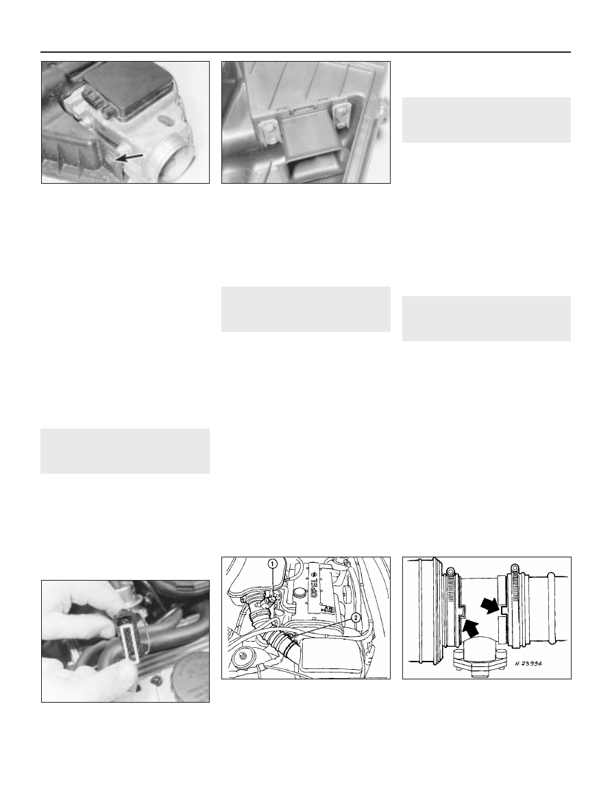
2 Loosen the clamp screw and disconnect
the air trunking from the airflow meter (see
illustration).
3 Disconnect the battery negative lead, then
disconnect the wiring plug from the airflow
meter.
4 Release the two securing clips from the left-
hand side of the air cleaner cover, and
unscrew the two captive securing screws
from the right-hand side, then lift off the
cover.
5 Lift out the filter element.
6 Loosen the preheat hoses, fastening nuts.
7 Undo the nuts securing the 2 rubber block
studs which are secured through the lower
half of the air cleaner housing.
8 Some models are fitted with an inlet air
resonance box, to reduce induction noise.
This box is located under the wheel arch, and
connects to a pipe on the air inlet tube.
9 The resonance box must be removed
before the air inlet tube can be removed. To
do this, first apply the handbrake, then jack up
the front of the vehicle, and support securely
on axle stands placed under the body side
members.
10 Remove the securing screws, and
withdraw the lower splash shield from the
wing to expose the resonance box.
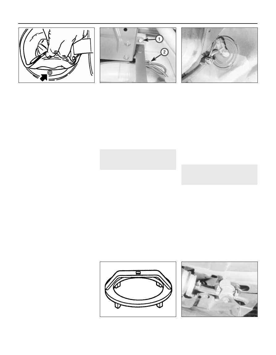
11 Unscrew the single securing screw, and
pull the resonance box from the connector
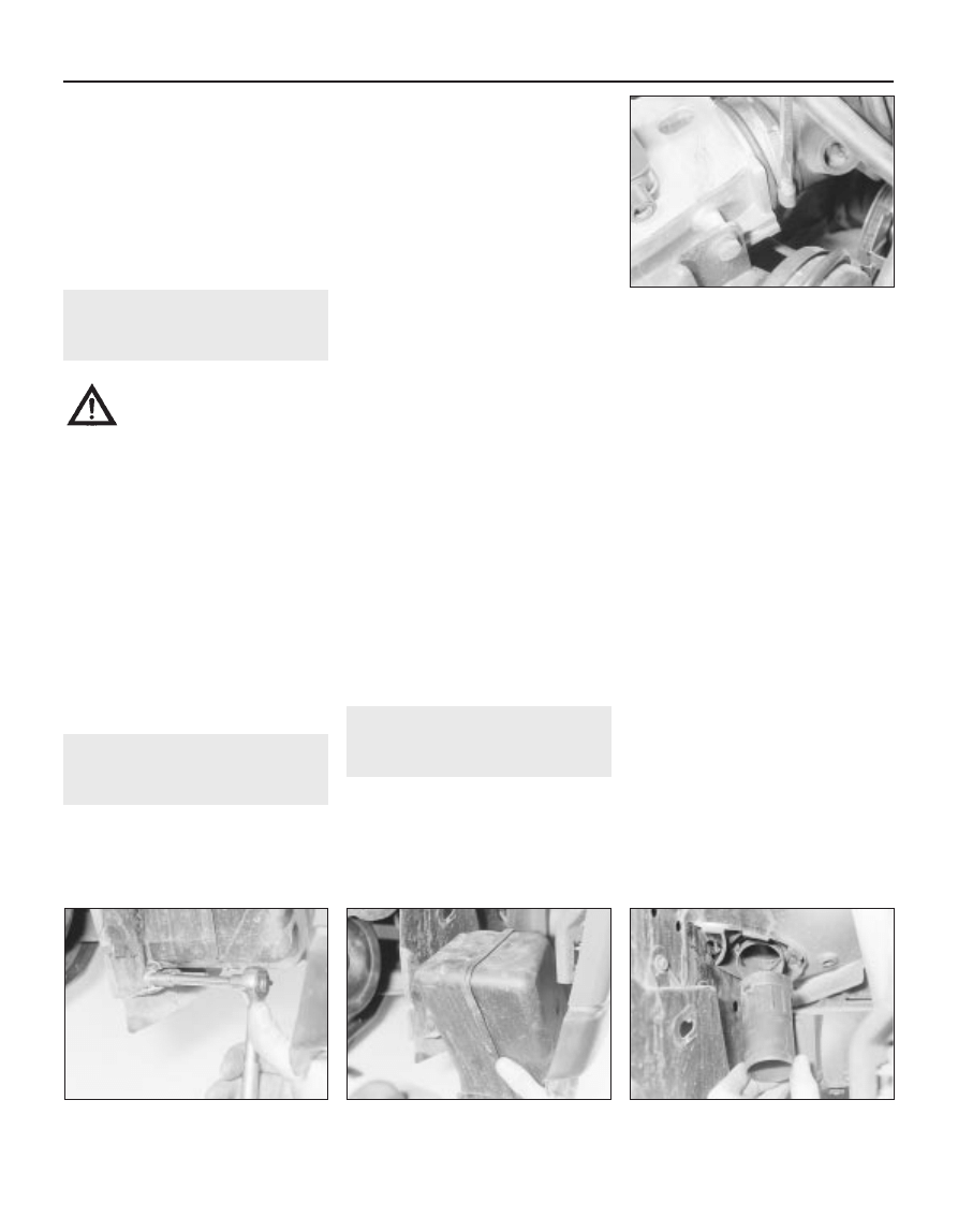
tube (see illustrations).
12 If desired, the air inlet tube can be
removed after pulling off the connector tube
from under the wing (see illustration).
4B•4 Fuel and exhaust systems - fuel injection models
4.12 Removing the resonance box
connector tube
4.11B . . . and withdraw the resonance box
4.11A Remove the securing screw . . .
4.2 Loosening the air trunking clamp
screw at the airflow meter
Warning: Many of the
procedures in this sub-Section
require the removal of fuel lines
and connections that may result
in some fuel spillage. Before carrying out
any operation on the fuel system refer to
the precautions given in Safety first! at
the beginning of this Manual and follow
them implicitly. Petrol is a highly
dangerous and volatile liquid, and the
precautions necessary when handling it
cannot be overstressed.
4B
13 Manipulate the air inlet tube to release the
securing lugs from the front body panel. This
is a tricky operation, and patience will be
required. For improved access, the headlamp
can be removed, as described in Chapter 12.
Refitting
14 Refitting of all components is a reversal of
removal, noting that the air cleaner element
fits with the rubber locating flange uppermost.
5
Air box - removal and refitting
2
Removal
1 The air box, if fitted, is secured by two or
three bolts to the top of the throttle body.
Take note of the routing and connections of
the inlet air temperature control system
vacuum pipes.
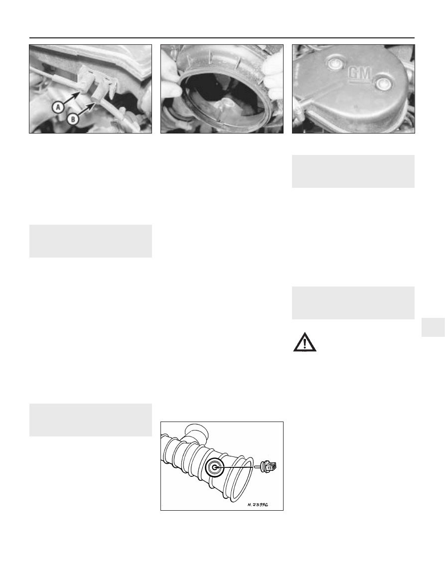
2 Disconnect the engine breather hose from
the air box and the vacuum pipe from the
rearmost of the throttle body’s three unions
(see illustration).
3 Do not lose the sealing ring as the air box is
withdrawn.
Refitting
4 On refitting, ensure that the sealing ring is
seated correctly in the slot in the underside of
the air box, tighten the screws, and reconnect
the vacuum pipe and breather hose (see
illustrations).
6
Air temperature control -
description and testing
3
Description
1 Fitted to models with Multec systems, air
temperature is controlled by a thermac switch
(thermostat), mounted in the air box. When
the engine is started from cold, the switch is
closed to allow inlet manifold depression to
act on the air temperature control valve in the
air cleaner assembly. This uses a vacuum
servo in the valve assembly to draw a flap
valve across the cold air inlet thus allowing
only (warmed) air from the exhaust manifold to
enter the air cleaner.
2 As the temperature of the exhaust warmed
air in the air box rises, a bi-metallic strip in the
thermac switch deforms. This opens the
switch to shut off the depression in the air
temperature control valve. The flap is then
lowered gradually across the hot air inlet. Until
the engine is fully warmed up to normal
operating temperature, only cold air from the
front of the vehicle is entering the air cleaner.
Testing
3 To check the system, allow the engine to
cool down completely, then remove the air
cleaner cover; the flap valve should be
securely seated across the hot air inlet. Start
the engine. The flap should immediately rise to
close off the cold air inlet. It should then lower
steadily as the engine warms until it is
eventually seated across the hot air inlet again.
4 To check the thermac switch, disconnect
the control valve vacuum pipe from the switch
union (on the rear face of the air box) when the
engine is running. With the engine cold, full
inlet manifold depression should be felt
sucking at the union; none at all should be felt
when the engine is fully warmed up.
5 To check the air temperature control valve,
remove the air cleaner cover; the flap valve
should be securely seated across the hot air
inlet. Disconnect the control valve vacuum
pipe from the switch union on the rear face of
the air box and suck hard on its end; the flap
should rise to shut off the cold air inlet.
6 If either component is faulty, it must be
renewed. This means renewing the air cleaner
lower casing to obtain a new air temperature
control valve, or renewing the air box in the
case of the thermac switch.
7
Air temperature sensor (later
models) - removal and
refitting
2
Removal
1 Disconnect the battery negative lead.
2 Disconnect the wiring plug at the inlet air
temperature sensor.
3 Release the hose clips and remove the air
trunking then remove the inlet air temperature
sensor from the trunking.
Refitting
4 Refitting is a reversal of removal but ensure
that the air trunking is connected to the
airflow meter as shown (see illustration).
8
Depressurising the fuel
system - general
2
General
1 The fuel system consisting of the
tank-mounted fuel pump, the fuel filter, the
fuel injector and the pressure regulator in the
throttle body. Metal pipes and flexible hoses
of the fuel lines connect these components.
All these contain fuel that will be under
pressure while the engine is running and/or
while the ignition is switched on.
2 The pressure will remain for some time after
the ignition has been switched off and must
be relieved before any of these components
are disturbed.
3 Remove either the fuel pump fuse (num-
ber 11) or the fuel pump relay and start the
engine. Allow the engine to idle until it cuts
out. Turn the engine over once or twice on the
starter to ensure that all pressure is released,
then switch off the ignition.
4 Do not forget to refit the fuse or relay when
work is complete.
Fuel and exhaust systems - fuel injection models 4B•5
5.4B Do not overtighten the air box
screws
7.4 Removing the intake air temperature
sensor from the air trunking - later models
5.4A Ensure the sealing ring is located in
the air box groove
5.2 Vacuum pipe connections to air box
A To throttle body B To air cleaner
Warning: The following
procedures will merely relieve
the pressure in the fuel system.
Remember that fuel will still be
present in the system components, so
take precautions before disconnecting
any of them. Refer to Section 2.
9
Fuel filter (‘Out-of-tank’ fuel
pump models) - removal and
refitting
3
Note: Refer to Section 2 before proceeding
Removal
1 The fuel filter is located on the fuel pump
bracket under the rear of the vehicle. Either on
the right-hand side of the spare wheel well or
in front of the fuel tank, depending on model
(see illustrations).
2 Disconnect the battery negative lead.
3 Have a container to hand, to catch the fuel
that will be released as the filter is removed.
4 Clamp the fuel hoses on either side of the
filter, to minimise fuel loss when the hoses are
disconnected.
5 Loosen the clamp screws, and disconnect
the fuel hoses from the filter. Be prepared for
fuel spillage, and take adequate fire
precautions.
6 Loosen the clamp bolt(s), and withdraw the
fuel filter from its bracket. Note the orientation
of the flow direction arrow on the body of the
filter, and the position of the “AUS” (out)
marking on the filter end face.
Refitting
7 Refitting is a reversal of removal, ensuring
that the flow direction markings are correctly
orientated.
8 Run the engine and check for leaks on
completion. If leakage is evident, stop the
engine immediately, and rectify the problem
without delay.
10 Fuel filter (‘In-tank’ fuel
pump models) - removal and
refitting
3
Note: Refer to Section 2 before proceeding
Removal
1 Depressurise the fuel system (Section 8).
2 Chock the front wheels, jack up the rear of
the vehicle and support it on axle stands
placed under the body side members. (see
“Jacking and Vehicle Support”). The fuel filter
is located at the rear of the fuel tank, on the
right-hand side.
3 Unclip the fuel hose from the filter mounting
bracket.
4 Note carefully any markings on the fuel filter
casing. There should be at least an arrow
(showing the direction of fuel flow) pointing in
the direction of the fuel supply hose leading to
the engine compartment. There may also be
the words “EIN” (in) and “AUS” (out)
embossed in the appropriate end of the
casing.
5 Clamp the fuel filter hoses, then slacken the
clips and disconnect the hoses.
6 Undo the single screw to release the
mounting bracket, then open the clamp with a
screwdriver to remove the fuel filter (see
illustration).
Refitting
7 Fit the new fuel filter using a reversal of the
removal procedure, but ensure that the fuel
flow direction arrow or markings point in the
correct direction. Switch on the ignition and
check carefully for leaks; if any signs of
leakage are detected, the problem must be
rectified before the engine is started.
11 Fuel pump - testing
2
Testing
1 If the fuel pump is functioning, it should be
possible to hear it “buzzing” by listening
under the rear of the vehicle when the ignition
is switched on. Unless the engine is started,
the fuel pump should switch off after
approximately one second. If the noise
produced is excessive, this may be due to a
faulty fuel flow damper. The damper can be
renewed referring to Section 18, if necessary.
2 If the pump appears to have failed
completely, check the appropriate fuse and
relay.
3 To test the fuel pump, special equipment is
required, and it is recommended that any
suspected faults are referred to a Vauxhall
dealer.
12 Fuel pump (‘Out-of-tank’ fuel
pump models) - removal and
refitting
3
Note: Refer to Section 2 before proceeding
Removal
1 The fuel pump is located on a bracket
under the rear of the vehicle, either on the
right-hand side of the spare wheel well or in
front of the fuel tank on other models.
2 Disconnect the battery negative lead.
3 Have a container to hand, to catch the fuel
that will be released as the damper is
removed.
4 Disconnect the wiring plug(s) from the fuel
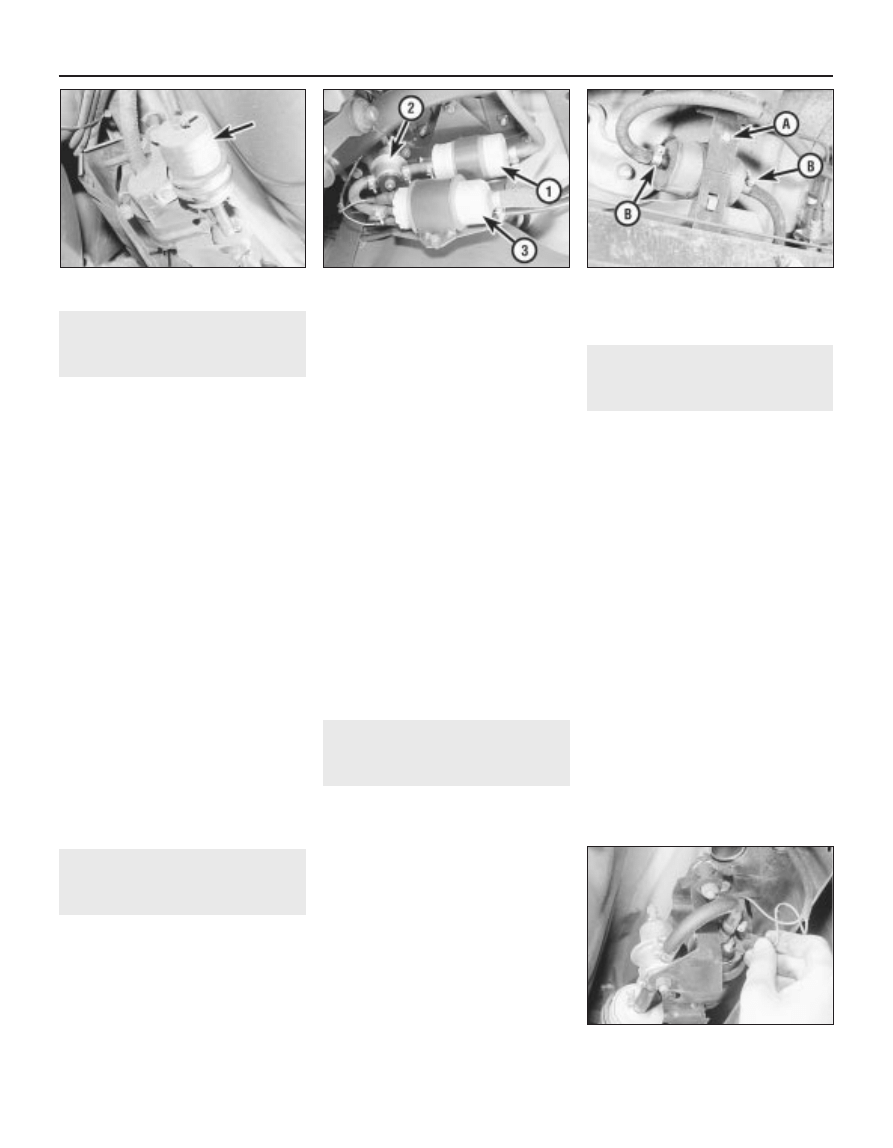
pump (see illustration).
5 Clamp the fuel hoses on either side of the
damper, to minimise fuel loss when the hoses
are disconnected.
6 Loosen the clamp screws, and disconnect
the fuel hoses from the pump. Be prepared for
fuel spillage, and take adequate fire
precautions.
7 Loosen the clamp bolt, and slide the pump
from its bracket.
Refitting
8 Refitting is a reversal of removal, ensuring
that the pump is fitted the correct way round
in its bracket. Push the pump into the rubber
clamping sleeve as far as the rim on the pump
body (see illustration).
4B•6 Fuel and exhaust systems - fuel injection models
9.1A Fuel filter (arrowed) - ‘out of tank’,
fuel pump models
10.6 Fuel filter - ‘in tank’, fuel pump type
A Clamp screw
B Hose clips
12.4 Disconnecting a fuel pump wiring
plug - ‘out of tank’, fuel pump model
9.1B Fuel component assembly - ‘out of
tank’, fuel pump models
1 Fuel filter
2 Fuel flow damper
3 Fuel pump
4B
9 Run the engine and check for leaks on
completion. If leakage is evident, stop the
engine immediately, and rectify the problem
without delay.
13 Fuel pump (‘In-tank’ fuel
pump models) - removal and
refitting
3
Removal
1 Depressurise the fuel system (Section 8),
then remove and refit the fuel filler cap to
ensure that the pressure is equalised inside
and outside the tank.
2 Disconnect the battery negative terminal.
3 Fold forwards the rear seat cushion. Peel
back the floor covering beneath it, then
remove the cover plug from the vehicle floor
to reach the pump mountings (see
illustration).
4 Noting exactly how it is connected, and
making your own marks or notes to ensure
that it can be reconnected the same way
round, disconnect the wiring plug from the
pump.
5 Release the securing clip and disconnect
the fuel hose from the pump. Clamp or plug
the hose to prevent the loss of fuel and the
entry of dirt.
6 Undo the pump mounting bracket screws,
then withdraw the mounting bracket and
pump assembly from the tank. Note the
position of the sealing ring and discard it, then
cover the tank opening as a safety measure
and to prevent the entry of dirt.
7 If the pump is to be renewed, first move it to
a clean working area and carry out the
following.
8 Prise off the filter at the base of the pump
assembly, then release the securing clamp
and disconnect the mounting
bracket-to-pump fuel hose.
9 Making your own marks or notes to ensure
that they can be reconnected the same way
round, unsolder the wires connecting the
pump to the mounting bracket.
10 Press the pump out of the rubber sleeve.
Refitting
11 Reassembly and refitting are the reverse
of the removal and dismantling procedures,
noting the following points.
a) Ensure that the pump is seated correctly
in the sleeve and that the hose is securely
fastened.
b) Ensure that the wires are correctly
reconnected and securely soldered.
c) Always renew the pump mounting
bracket’s sealing ring.
d) Apply a few drops of sealing compound
(i.e. Vauxhall part no. 90485251) to the
threads of the screws, then tighten them
securely, but take care not to distort the
sealing ring.
14 Fuel pump relay - renewal
2
The relay is mounted in the engine
compartment relay box (Chapter 12). Where
more than one relay is fitted, the fuel pump
relay is the one with the black base.
15 Fuel tank filler pipe - removal
and refitting
3
Removal
1 Syphon out any remaining fuel in the tank
into a clean container that is designed for
carrying petrol and is clearly marked as such.
2 Raise the bottom edge of the seal
surrounding the filler neck and undo the single
securing screw beneath.
3 Chock the front wheels, jack up the rear of
the vehicle and support it securely on axle
stands (see “Jacking and Vehicle Support”)
placed under the body side members.
4 Unscrew the single filler pipe mounting bolt
from the underbody, then work along the
length of the pipe, cutting or releasing any
clips or ties securing other pipes or hoses to
it. Releasing their clips, disconnect the filler
and vent hoses from the pipe’s lower end and
the small-bore vent hoses from the unions at
its upper end.
5 Having ensured that all components have
been removed or disconnected which might
prevent its removal, manoeuvre the pipe away
from the vehicle’s underside.
6 To check the operation of the pipe’s
anti-leak valve, invert the filler pipe and fill the
lower union (now uppermost) with petrol. If
the valve is functioning correctly, no petrol will
leak from the other union. If petrol leaks from
the other union the valve is faulty and the
complete filler pipe must be renewed.
Refitting
7 Refitting is the reverse of the removal
procedure, noting the following.
a) Check the condition of all hoses and
clips, renewing any components that are
found to be worn or damaged
b) When reconnecting the small-bore vent
hoses to the unions at the pipe’s upper
end, connect the hose from the charcoal
canister to the uppermost union and the
vent hose from the tank itself to the lower
union (see illustration).
c) Replacing any that were cut on removal
use the clips or ties provided to secure
any other pipes or hoses to the filler pipe.
d) Check carefully for signs of leaks on
refilling the tank; if any signs of leakage
are detected, the problem must be
rectified immediately.
16 Fuel tank - removal and
refitting
4
Note: Refer to Section 2 before proceeding
Removal
SOHC models
1 The procedure is similar as for models with
carburettors. Refer to Chapter 4A, however
note the following:
a) Depressurise the fuel system (Section 8).
b) On models with C16 NZ and X16 SZ
engines, disconnect the exhaust system
from the manifold.
c) When working on the fuel tank sender
unit, note that there is only one hose to be
disconnected.
Fuel and exhaust systems - fuel injection models 4B•7
15.7 Vent hose connections at fuel tank
filler pipe
A Charcoal canister hose
B Tank vent hose
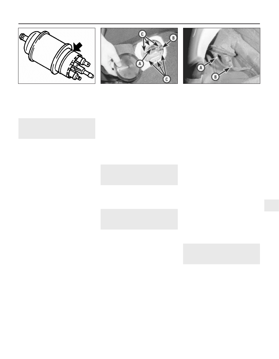
13.3 Fuel pump - ‘in-tank’, fuel pump
model
A Wiring connector
B Fuel hose clamp
C Mounting bracket
screws
12.8 Fuel pump clamping sleeve should
rest against rim (arrowed)
d) Disconnect the fuel pump hose and wiring
as described in Section 12.
e) When releasing the tank mounting straps,
note that the fuel filter must either be
moved aside or removed completely,
whichever is most convenient
f) One of the fuel hoses connects to a pipe
in the side of the tank.
DOHC models
2 Disconnect the battery negative lead.
3 Siphon out any remaining fuel in the tank
through the filler pipe. Siphon the fuel into a
clean metal container that can be sealed.
4 Chock the front wheels, then jack up the
rear of the vehicle, and support on axle stands
placed under the body side members (see
“Jacking and Vehicle Support”).
5 Open the fuel filler flap, then pull back the
rubber seal to expose the fuel filler pipe
securing screw (see illustration). Remove the
screw.
6 Release the fuel tank vent hoses from the
clips on the underbody.
7 Support the weight of the fuel tank on a
jack, with an interposed block of wood.
8 Unscrew the securing bolts from the tank
mounting straps. Then remove the straps and
lower the tank sufficiently to enable the fuel
hoses, vent hoses and fuel tank sender unit
wiring to be disconnected (see illustration).
9 Disconnect the vent hoses and the fuel tank
sender unit wiring. Note the positions of the
vent hoses as an aid to refitting.
10 Disconnect the fuel hoses from the tank and
the fuel tank sender unit, making a note of the
hose positions for use when refitting. Be
prepared for fuel spillage, and take adequate fire
precautions. Plug the open ends of the hoses, to
prevent dirt ingress and further fuel loss.
11 Lower the fuel tank, and withdraw it from
under the vehicle.
12 If the tank contains sediment or water, it
may be cleaned out using two or three rinses
with clean fuel. Shake vigorously using
several changes of fuel, but before doing so,
remove the fuel tank sender unit, as described
in Section 17. This procedure should be
carried out in a well-ventilated area, and it is
vital to take adequate fire precautions - refer
to the “Safety first!” Section at the beginning
of this manual for further details.
Refitting
13 Any repairs to the fuel tank should be
carried out by a professional.
14 Refitting is a reversal of removal, ensuring
that all hoses are reconnected to their correct
locations as noted during removal.
15 On completion, fill the fuel tank, then run
the engine and check for leaks. If leakage is
evident, stop the engine immediately, and
rectify the problem without delay.
17 Fuel tank sender unit -
removal and refitting
3
Note: Refer to Section 2 before proceeding
Removal
SOHC models
1 Remove the fuel tank, (refer to Section 16),
if necessary. Note that there is only one hose
connected to the sender unit. This must also
be disconnected from the union on the inside
of the unit before it can be withdrawn
completely from the tank (see illustration).
DOHC models
2 Remove the fuel tank, as described in
Section 16.
3 Make alignment marks on the sender unit
and the fuel tank so that the sender unit can
be refitted in its original position.
4 To remove the sender unit, an improvised
tool must be used which engages with the
cut-outs in the sender unit retaining ring. The
Vauxhall special tool KM-673 for this purpose
is shown (see illustration).
5 Withdraw the unit carefully, to avoid
bending the float arm.
6 Recover the sealing ring.
Refitting
7 Refitting is a reversal of removal,
remembering the following points.
8 Renew the sealing ring.
9 Ensure that the marks made on sender unit
and fuel tank before removal are aligned.
10 Refit the fuel tank, (Section 16).
18 Fuel flow damper - removal
and refitting
3
Note: Refer to Section 2 before proceeding
Removal
1 The fuel flow damper is located on the fuel
pump bracket under the rear of the vehicle, on
the right-hand side of the spare wheel well or
in front of the fuel tank, depending on model
(see illustration). The damper is positioned in
the fuel feed line between the fuel pump and
the fuel filter, and its purpose is to reduce
pressure fluctuations in the fuel return line,
thus reducing noise levels.
2 Disconnect the battery negative lead.
3 Have a container to hand, to catch the fuel
that will be released as the damper is
removed.
4B•8 Fuel and exhaust systems - fuel injection models
16.5 Fuel filler pipe securing screw
(arrowed) - models with semi-trailing arm
rear axles
17.1 Fuel level sender unit - models with
semi-independent rear axles
18.1 Fuel flow damper - models with semi-
trailing arm rear axles
17.4 Vauxhall special tool KM-673 for
removing fuel level sender units
16.8 Fuel tank mounting - models with
semi-trailing arm rear axles
1 Strap securing bolt 2 Vent hose securing
4B
4 Clamp the fuel hoses on either side of the
damper, to minimise fuel loss when the hoses
are disconnected.
5 Loosen the clamp screws, and disconnect
the fuel hoses from the damper. Be prepared
for fuel spillage, and take adequate fire
precautions.
6 Unscrew the securing nut, and withdraw
the damper from the bracket.
Refitting
7 Refitting is a reversal of removal.
8 Run the engine and check for leaks on
completion. If leakage is evident; stop the
engine immediately, and rectify the problem
without delay.
19 Throttle cable - removal,
refitting and adjustment
3
Removal
1 This procedure is basically the same as
described in Chapter 4A, but note the
following.
2 Not all models are fitted with an air box.
Ignore references to it, if not applicable.
3 For “carburettor” substitute “throttle body”,
and note that the cable bracket is bolted to
the inlet manifold.
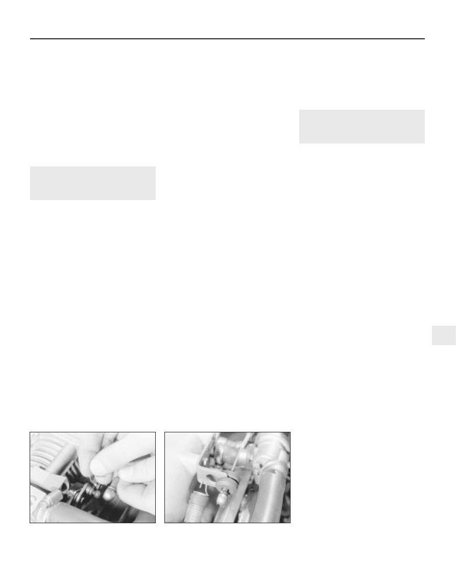
4 The throttle cable end may connect to a
balljoint on the throttle valve lever, which is
retained by a clip (see illustration).
5 If fitted, remove the air box. Refer to
Section 5, if necessary.
6 Where fitted, use a pair of needle-nosed
pliers to extract the wire spring clip securing
the cable end balljoint to the throttle linkage.
Prise the cable end off the linkage.
7 Withdraw the clip and pull the cable outer
seating grommet out of the cable bracket,
then release the cable as far as the bulkhead
(see illustration).
8 Working inside the passenger
compartment, remove the driver’s footwell
trim panel, refer to Chapter 11, if necessary.
9 Release the end of the cable’s inner wire
from the “keyhole” fitting at the top of the
throttle pedal by easing back the spring and
prising the cable end out of the slot.
10 Prise the grommet out of the bulkhead
and tie a length of string to the cable.
11 Noting carefully its routing, withdraw the
cable through the bulkhead into the engine
compartment; untie the string, leaving it in
place, when the pedal end of the cable
appears.
Refitting
12 Refitting is the reverse of the removal
procedure, noting the following points.
a) First ensure that the cable is correctly
routed, then draw it through the bulkhead
aperture using the string.
b) Ensure that the bulkhead grommet is
correctly seated.
c) Connect the cable end to the throttle
linkage. Seat the cable outer grommet in
the bracket and pull it through so that the
cable inner wire is just taut when the
throttle linkage is held fully closed. Fit the
clip to secure the cable outer in that
position.
d) Check the throttle operation and cable
adjustment, as described below.
Adjustment
13 Refer to Chapter 4A, but for “carburettor”
substitute “throttle body”. If applicable, the air
box must be removed.
14 First check that the pedal is at a
convenient height for the driver. This setting
can be adjusted by turning the pedal stop
screw (it will be necessary to remove the
footwell trim panel to reach the screw).
Remember that the pedal must be left with
enough travel for the throttle valve to open
fully. Also check that the pedal pivot bushes
are in good condition.
15 Returning to the engine compartment,
check that the linkage pivots and balljoints are
unworn and operate smoothly throughout
their full travel. When the throttle valve is fully
closed and the throttle pedal is released, there
should be hardly any free play in the cable
inner wire.
16 If adjustment is required, extract the clip
securing the cable outer seating grommet in
the cable bracket and replace it in the
appropriate groove, so that the cable outer is
repositioned correctly.
17 With an assistant operating the throttle
pedal from the driver’s seat. Check that when
the pedal is fully depressed, the throttle valve
is fully open. If there is insufficient pedal travel
to permit this, unscrew the pedal stop screw,
then reset the cable at the throttle linkage.
18 When cable adjustment is correct, refit all
disturbed components.
20 Idle mixture - checking and
adjustment
3
Note: No adjustment of idle mixture is
possible on models fitted with a catalytic
converter, and no adjustment of idle speed is
possible with the Motronic system. Refer to
Section 2 before proceeding. A tachometer
and an exhaust gas analyser (CO meter) will be
required to carry out adjustment on models
fitted with Motronic systems.
Multec systems
Checking
1 If the CO level reading is incorrect (or if any
other symptom is encountered which causes
you to suspect a fault) always check first that
the air cleaner element is clean. Check also
that the spark plugs are in good condition and
correctly gapped. Ensure that the engine
breather and vacuum hoses are clear and
undamaged. Check that there are no leaks in
the air inlet trunking. Check the throttle body
and the manifolds for damage. Ensure that the
throttle cable is correctly adjusted (see Section
19). If the engine is running very roughly, check
the compression pressures (Chapter 2A) and
remember the possibility that one of the
hydraulic tappets might be faulty, producing
an incorrect valve clearance. Check also that
all wiring is in good condition, with securely
fastened connectors. Check that the fuel filter
has been renewed at the recommended
intervals and that the exhaust system is
entirely free of air leaks which might upset the
operation of the catalytic converter, if fitted.
Adjustment
2 The idle mixture is controlled entirely by the
ECU and there is no provision at all for any
form of adjustment. Furthermore, accurate
checking is not possible without the use of
Vauxhall test equipment in conjunction with a
good-quality, carefully calibrated exhaust gas
analyser.
3 While it may be possible for owners with
access to such analysers to check the
mixture, the results should be regarded as no
more than a rough guide. If the mixture is
thought to be incorrect, the vehicle should be
taken to a Vauxhall dealer for checking. If the
CO level exceeds the specified value the
system must be checked thoroughly by an
experienced mechanic using the Vauxhall test
equipment until the fault is eliminated and the
defective component renewed.
Fuel and exhaust systems - fuel injection models 4B•9
19.7 Throttle cable end grommet in
bracket on inlet manifold
19.4 Disconnecting the throttle cable end
from the throttle valve lever - SOHC model
4 Where applicable, the only test of the
catalytic converter’s efficiency is to check the
level of CO in the exhaust gas. This is
measured at the tailpipe with the engine
running (with no load) at 3000 rpm. If the CO
level exceeds the specified value, the Vauxhall
test equipment must be used to check the
entire fuel injection/ignition system. If the
engine is mechanically sound, once the
system has been eliminated, the fault must lie
in the converter, which must be renewed.
Motronic systems
Checking
5 In order to check the idle mixture adjustment,
the following conditions must be met:
a) The engine must be at normal operating
temperature
b) All electrical consumers (cooling fan,
heater blower, headlamps etc.) must be
switched off
c) The spark plug gaps must be correctly
adjusted see Chapter 1
d) The throttle cable free play must be
correctly adjusted - see Section 19
e) The air inlet trunking must be free from
leaks, and the air filter must be clean
Adjustment
6 Connect a tachometer and an exhaust gas
analyser to the vehicle in accordance with the
equipment manufacturer’s instructions.
7 Start the engine and turn it at 2000 rpm for
approximately 30 seconds, then allow it to
idle. Check that the idle speed is within the
specified limits. No adjustment of idle speed
is possible, and if outside the specified limits,
the problem should be referred to a dealer.
8 With the idle speed correct, check the CO
level in the exhaust gas. If it is outside the
specified limits, adjust by means of the idle
mixture adjustment screw in the airflow meter
or air mass meter, as applicable. In
production, the screw is covered by a
tamperproof plug; ensure that no local or
national laws are being broken before
removing the plug.
9 If the cooling fan cuts in during the
adjustment procedure, stop the adjustments,
and proceed when the cooling fan stops.
10 When the idle mixture is correctly set,
stop the engine and disconnect the test
equipment.
Simtec systems
11 Adjustment is not possible on these
models.
21 Fuel pressure regulator -
removal and refitting
3
Note: Refer to Section 2 before proceeding
Removal
SOHC models (except Multec systems)
1 Disconnect the battery negative lead.
2 For improved access, remove the idle
speed adjuster as described in Section 22.
Disconnect the wiring harness housing from
the fuel injectors and move it to one side,
taking care not to strain the wiring. Pull up on
the wiring harness housing, and compress the
wiring plug retaining clips to release the
harness housing from the injectors.
3 Position a wad of rag beneath the pressure
regulator, to absorb the fuel that will be
released as the regulator is removed.
4 Loosen the clamp screws and disconnect
the fuel hoses from the regulator. Be prepared
for fuel spillage, and take adequate fire
precautions.
5 Disconnect the vacuum pipe from the top
of the pressure regulator and withdraw the
regulator.
SOHC models (with Multec system)
6 Depressurise the fuel system, as described
in Section 8.
7 Remove the air box. Refer to Section 5, if
necessary.
8 Disconnect the battery earth lead.
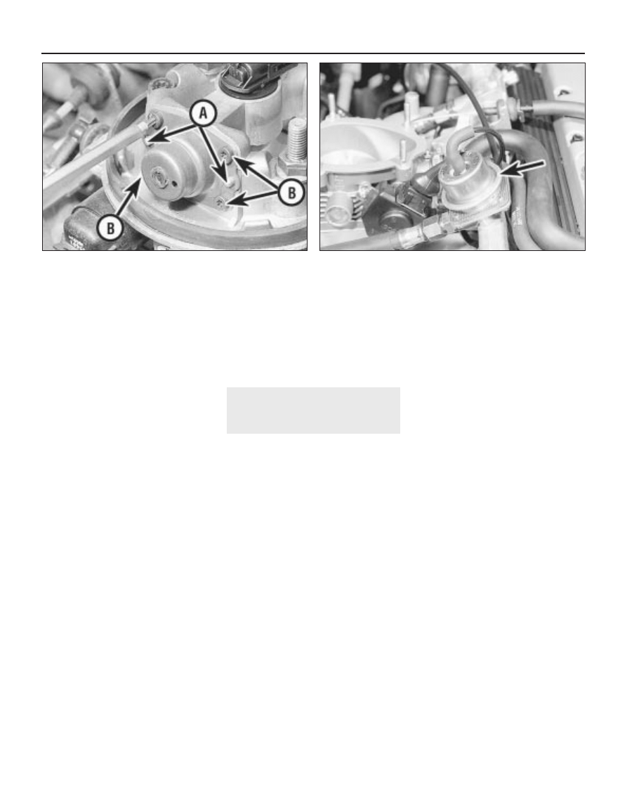
9 Noting the dowels locating the cover,
carefully unscrew the fuel pressure regulator
cover Torx-type screws (size TX 15). Ensure
that the spring does not fly out as the cover is
released. Remove the cover spring seat,
spring and diaphragm, noting how each is
fitted (see illustration).
10 The diaphragm must be renewed
whenever the cover is disturbed. If any of the
regulator’s other components are worn or
damaged, they can be renewed only as part
of the throttle body upper section assembly.
DOHC models
11 Disconnect the battery negative lead.
12 Disconnect the wiring plug from the air
mass meter. Recover the sealing ring.
13 Loosen the clamp screw securing the air
trunking to the right-hand end of the air mass
meter.
14 Using an Allen key or hexagon bit,
unscrew the four bolts securing the air box to
the throttle body. Lift the air box from the
throttle body and disconnect the hose from
the base of the air box, then withdraw the air
box/air mass meter assembly.
15 Disconnect the two breather hoses from
the rear of the camshaft cover, and move
them to one side.
16 Disconnect the wiring plug from the
throttle position sensor.
17 Disconnect the vacuum pipe from the top
of the pressure regulator (see illustration).
18 Position a wad of rag beneath the
regulator, to absorb the fuel that will be
released as the regulator is removed.
19 Using a spanner or socket, and working
underneath the regulator, unscrew the four
Torx type securing bolts, then withdraw the
regulator. Be prepared for fuel spillage, and
take adequate fire precautions.
Refitting
20 Refitting is a reversal of removal, ensuring
that all wires, pipes and hoses are correctly
reconnected. Note that on DOHC models, the
4B•10 Fuel and exhaust systems - fuel injection models
21.17 Fuel pressure regulator (arrowed) - DOHC model
21.9 Fuel pressure regulator cover
A Locating dowels B Mounting screws
regulator vacuum pipe should be routed over
the top of the camshaft cover breather hoses.
21 On models with the Multec system note
also the following:
a) Fit the new diaphragm so that it locates in
the throttle body groove.
b) Ensure that the spring and spring seat are
correctly engaged with each other and
with the diaphragm and regulator cover.
Then press the cover over its locating
dowels and hold it in place while the
screws are tightened.
c) Tighten the screws carefully to the
specified torque wrench setting.
22 On completion, check the regulator for
leaks, pressurising the system by switching
the ignition on and off several times, before
the engine is started.
22 Idle speed adjuster - removal
and refitting
3
Note: Idle speed adjustment on models fitted
with Multec systems, is not possible, as it is
controlled by the ECU. Refer to Section 1.
Removal
SOHC models (except Multec system)
1 Disconnect the battery negative lead.
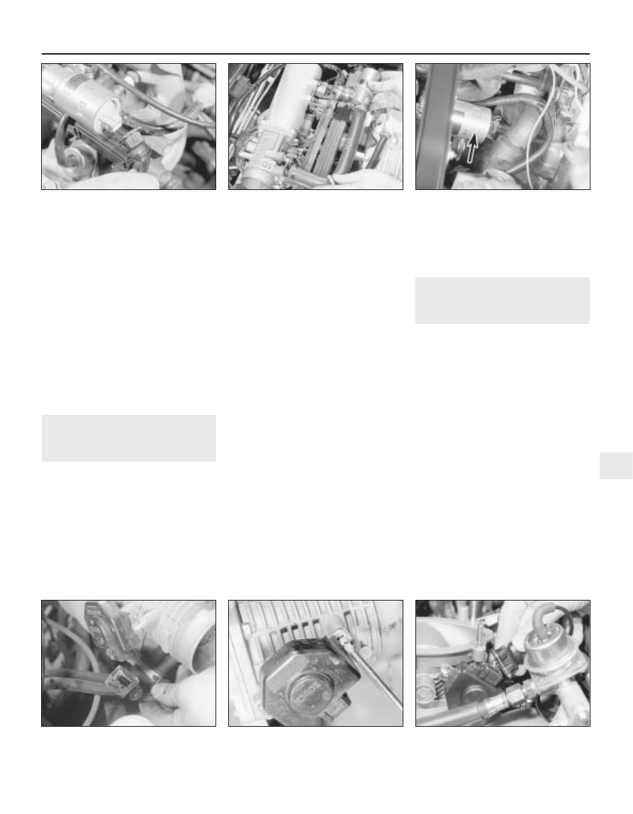
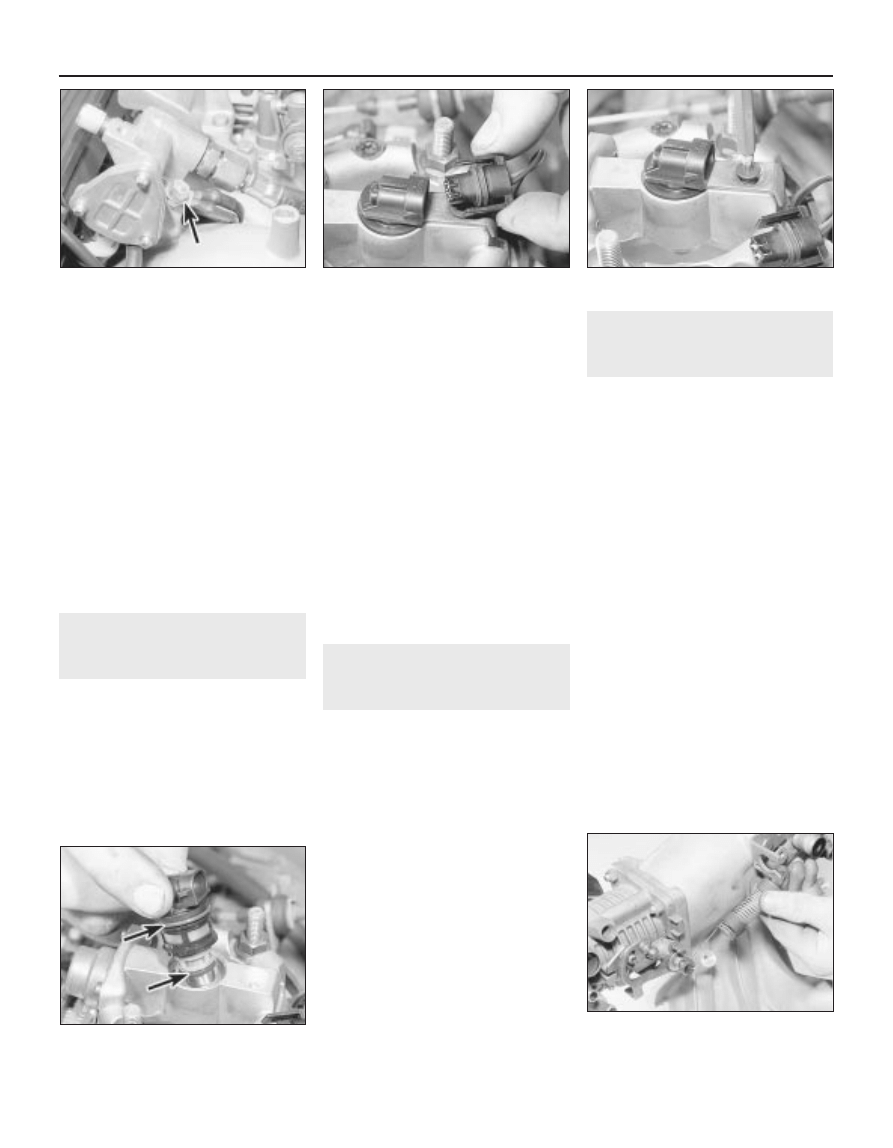
2 Disconnect the wiring plug from the idle
speed adjuster (see illustration).
3 The adjuster can be removed complete with
its connecting hoses, or separately, leaving
the hoses in place.
4 Loosen the relevant clamp screws, then
disconnect the hoses, and withdraw the idle
speed adjuster (see illustration).
DOHC models
5 Disconnect the battery negative lead.
6 Loosen the clamp screw, and disconnect
the hose from underneath the air box on the
throttle body. Remove the clamp from the
hose.
7 Apply the handbrake, then jack up the front
of the vehicle, and support securely on axle
stands (see “Jacking and Vehicle Support”)
placed under the body side members.
8 Remove the engine undershield, as
described in Chapter 11.
9 Working underneath the vehicle,
disconnect the wiring plug from the idle speed
adjuster, which is located underneath the inlet
manifold above the starter motor (see
illustration).
10 Loosen the clamp screw and disconnect
the remaining idle speed adjuster hose from
the inlet manifold, then withdraw the adjuster
downwards complete with the hoses.
11 If the hoses are to be removed from the
adjuster, mark their locations before removal
so that they can be correctly reconnected.
Once the adjuster has been refitted, it is
impossible to swap the hose positions.
Refitting
12 Refitting is a reversal of removal. On
DOHC models ensure that the idle speed
adjuster rests horizontally, with the wiring
routed over the top of the coolant hose. If the
wiring is routed under the coolant hose, this
may cause the idle speed adjuster to be bent
downwards, resulting in a restriction or
fracture in the air hose to the inlet manifold.
23 Throttle position sensor -
removal and refitting
3
Removal
SOHC models
1 Disconnect the battery negative lead.
2 Disconnect the wiring plug from the throttle
position sensor (see illustration).
3 Remove the two securing screws and
withdraw the sensor from the throttle body
(see illustration).
DOHC models
4 Disconnect the battery negative lead.
5 Disconnect the wiring plug from the air
mass meter. Recover the sealing ring.
6 Loosen the clamp screw securing the air
trunking to the right-hand end of the air mass
meter.
7 Using an Allen key or hexagon bit, unscrew
the four bolts securing the air box to the
throttle body. Lift the air box from the throttle
body, and disconnect the hose from the base
of the air box, then withdraw the air box/air
mass meter assembly.
8 Disconnect the wiring plug from the throttle
position sensor wiring plug (see illustration).
Fuel and exhaust systems - fuel injection models 4B•11
22.9 Idle speed adjuster (arrowed) viewed
from underneath vehicle -
DOHC model
23.8 Disconnecting the throttle position
sensor wiring plug - DOHC model
23.3 Removing a throttle position sensor
securing screw - SOHC early model
23.2 Disconnecting the throttle position
sensor wiring plug - early SOHC models
22.4 Withdrawing the idle speed adjuster
complete with hoses - SOHC model
(except with Multec systems)
22.2 Disconnecting the idle speed adjuster
wiring plug - SOHC models (except with
Multec systems)
4B
9 Remove the two securing screws and
withdraw the sensor from the throttle body.
Refitting
10 Refitting is a reversal of removal.
11 On Motronic M4.1 system models, before
tightening the securing screws, adjust the
position of the sensor as follows:
a) Turn the sensor body anti-clockwise until
resistance is felt, then tighten the securing
screws.
b) When the throttle valve is opened, an
audible click should be noticeable from
the sensor, and similarly, this should be
repeated as the throttle valve is closed.
c) If necessary, adjust the position of the
sensor until a click is heard just as the
throttle valve begins to open.
12 On M 1.5 systems, no adjustment is
required when refitting, as the sensor can only
be fitted in one position.
24 Throttle valve potentiometer
- removal and refitting
3
Removal
1 Disconnect the battery negative lead.
2 Disconnect the wiring plugs at the inlet air
temperature sensor and at the hot film mass
airflow meter.
3 Undo and remove the bolts securing the air
box to the throttle body. Remove the air box
complete with air trunking.
4 Disconnect the wiring plug at the throttle
valve potentiometer, then undo the two
screws and withdraw the potentiometer from
the throttle body.
Refitting
5 Refitting is a reversal of removal.
25 Airflow meter (if fitted) -
removal and refitting
3
Note: If the air funnel is removed, a new
gasket must be used on refitting. The airflow
meter securing bolts must be coated with
thread-locking compound on refitting
Removal
1 Remove the air cleaner assembly, as
described in Section 4.
2 Unscrew the single bolt securing the airflow
meter to the front of the air cleaner cover (see
illustration).
3 Unscrew the four securing bolts from inside
the air cleaner cover, recover the two
reinforcing plates, and withdraw the airflow
meter (see illustration).
4 If desired, the air funnel can be unclipped
from inside the air cleaner cover.
Refitting
5 Refitting is a reversal of removal,
remembering the following points.
6 If the air funnel has been removed, refit it
using a new gasket.
7 Coat the threads of the four airflow meter
securing bolts that fit inside the air cleaner
cover with thread-locking compound.
26 Air mass meter (if fitted) -
removal and refitting
3
Removal
1 Disconnect the battery negative lead.
2 Disconnect the wiring plug from the air
mass meter. Recover the sealing ring (see
illustration).
3 Loosen the clamp screws from the air
trunking on either side of the air mass meter,
then disconnect the air trunking and withdraw
the meter.
Refitting
4 Refitting is a reversal of removal, but
inspect the air mass meter wiring plug sealing
ring and renew if necessary.
27 Hot film mass airflow meter -
removal and refitting
3
Removal
1 Disconnect the battery negative lead.
2 Disconnect the wiring plug at the hot film
mass airflow meter and at the inlet air
temperature sensor.
3 Remove the upper part of the air cleaner
together with the inlet air trunking and air flow
meter.
4 Release the hose clamps and separate the
airflow meter from the inlet air trunking, noting
the position of the trunking with the air flow
meter. If there is any external damage replace
the unit.
Refitting
5 Refitting is a reversal of removal but ensure
that the air trunking is connected to the
airflow meter as shown (see illustration). Also
ensure that the marks on the air trunking and
air box are aligned as shown (see
illustration).
4B•12 Fuel and exhaust systems - fuel injection models
25.2 Airflow meter securing bolt (arrowed)
- SOHC model
26.2 Recover the sealing ring from the air
mass meter wiring plug - DOHC model
27.5B Correct attachment of air trunking to
hot film mass airflow meter - Motronic M2.8
Arrows indicate air trunking to airflow meter
alignment notches
27.5A Hot film mass airflow meter
attachments - Motronic M2.8
1 Hot film mass airflow meter wiring plug
2 Inlet air temperature sensor wiring plug
25.3 Airflow meter securing bolts and
reinforcing plates, and air funnel
28 Fuel injectors (except Multec
system) - removal and refitting
3
Note: Refer to Section 2 before proceeding.
New O-rings must be used when refitting the
injectors. Where applicable, a tachometer and
an exhaust gas analyser will be required to
check the idle mixture on completion
Removal
SOHC models
1 Disconnect the battery negative lead.
2 Unscrew the union nut, and disconnect the
brake servo vacuum hose from the inlet
manifold.
3 Remove the idle speed adjuster, complete
with hoses, referring to Section 22 if
necessary.
4 Disconnect the vacuum pipe from the top
of the fuel pressure regulator.
5 Disconnect the wiring harness housing from
the fuel injectors, and move it to one side,
taking care not to strain the wiring. Pull up on
the wiring harness housing, and compress the
wiring plug retaining clips to release the
harness housing from the injectors.
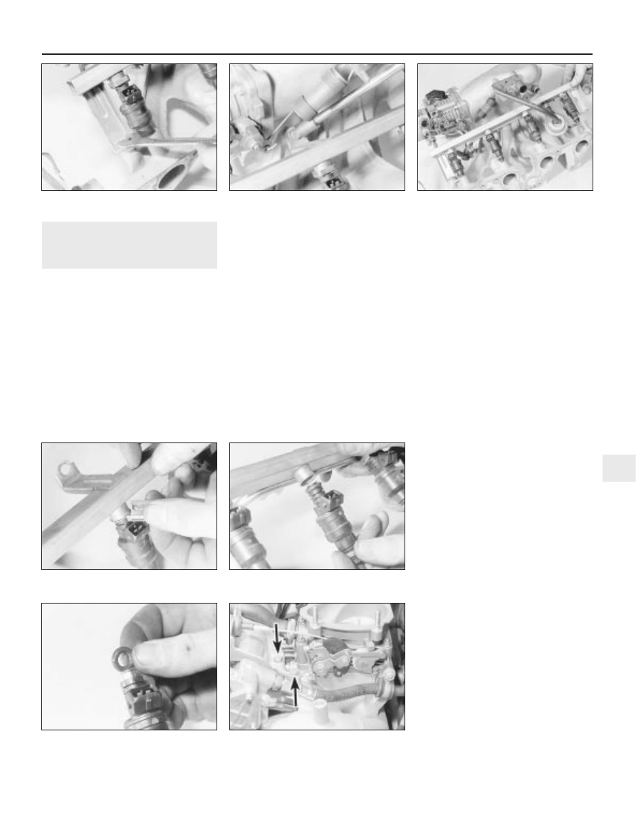
6 Remove the four bolts from the brackets
securing the fuel rail to the inlet manifold, then
lift the fuel rail complete with fuel injectors
sufficiently to enable the injector(s) to be
removed (see illustrations). Take care not to
strain the fuel hoses.
7 To remove an injector from the fuel rail,
prise out the metal securing clip using a
screwdriver, then pull the injector from the fuel
rail (see illustrations).
Refitting
8 Overhaul of the fuel injectors is not
possible, as no spares are available. If faulty,
an injector must be renewed.
9 Begin refitting by fitting new seals to both
ends of each fuel injector (see illustration).
Even if only one injector has been removed,
new seals should be fitted to all four injectors.
10 Refitting is a reversal of removal, ensuring
that all hoses, pipes and wires are correctly
reconnected.
11 On completion, where applicable, check
and if necessary adjust the idle mixture, as
described in Section 20.
DOHC models
Removal
12 Disconnect the battery negative lead.
13 Loosen the clamp screw securing the air
trunking to the left-hand end of the air mass
meter.
14 Using an Allen key or hexagon bit, unscrew
the four bolts securing the air box to the throttle
body. Lift the air box from the throttle body,
and disconnect the hose from the base of the
air box, then withdraw the air box.
15 Position a wad of rag beneath one of the
fuel hose unions on the fuel rail, to absorb the
fuel that will be released as the union is
disconnected.
16 Slowly loosen the fuel hose union to
relieve the pressure in the fuel line, then
disconnect the hose from the fuel rail. Be
prepared for fuel spillage, and take adequate
fire precautions. Plug the end of the fuel hose,
to prevent dirt ingress and further fuel leakage.
17 Repeat paragraphs 15 and 16 for the
remaining fuel hose-to-fuel rail union.
18 Disconnect the two breather hoses from
the rear of the camshaft cover. Disconnect the
larger hose from the throttle body, and
remove the hose completely.
19 Disconnect the vacuum pipe from the top
of the fuel pressure regulator.
20 Disconnect the wiring plug from the air
mass meter. Recover the sealing ring.
21 Disconnect the wiring plug from the
throttle position sensor.
22 Slide the end of the throttle cable from the
throttle valve lever on the throttle body, then
unbolt the cable bracket from the inlet
manifold, and move it to one side (see
illustration).
Fuel and exhaust systems - fuel injection models 4B•13
28.6C . . . and lift the fuel rail from the inlet
manifold (inlet manifold removed for
clarity) - SOHC model
28.22 Throttle cable bracket securing
bolts (arrowed) - DOHC model
28.9 Fit new seals to the injectors
28.7B . . . then pull the injector from the
fuel rail - SOHC model
28.7A Withdraw the securing clip . . .
28.6B . . . and inner fuel rail securing
bolts . . .
28.6A Remove the outer . . .
4B
23 Disconnect the wiring harness housing
from the fuel injectors, and move it to one
side, taking care not to strain the wiring. Pull
up on the wiring harness housing, and
compress the wiring plug retaining clips to
release the housing from the injectors.
24 Unscrew and remove the two fuel rail
securing nuts, and withdraw the fuel rail
complete with fuel injectors from the inlet
manifold. Note the position of the earth leads
on the fuel rail securing studs (see
illustration).
25 To remove an injector from the fuel rail,
prise out the metal securing clip using a
screwdriver, then pull the injector from the fuel
rail
Refitting
26 Refitting is as described in paragraphs 8
to 11 inclusive.
29 Fuel injector (Multec system)
- removal and refitting
3
Removal
1 Depressurise the fuel system (see Sec
tion 8).
2 Remove the air box (see Section 5).
3 Disconnect the battery earth lead.
4 Disconnect the wiring plug from the fuel
injector (see illustration).
5 Undo the Torx-type screw (size TX 20)
securing the fuel injector retainer to the top of
the throttle body, remove the retainer and lift
out the injector (see illustration). Remove
and discard the injector sealing rings.
Refitting
6 Refitting is the reverse of the removal
procedure, noting the following points.
a) Always renew both sealing rings; apply a
smear of grease to each to ease injector
refitting (see illustration).
b) Refit the injector so that its wiring
terminals point to the rear of the vehicle;
locate the edge of the retainer securely in
the groove at the top of the injector.
c) Apply a few drops of a thread-locking
compound to the screw threads, then
tighten it carefully to the specified torque
wrench setting.
d) Switch on the ignition and check carefully
for signs of fuel leaks; if any signs of
leakage are detected, the problem must
be rectified before the engine is started.
30 Fuel injector (Multec system)
- testing
3
1 A simple test of the injector’s windings is
possible for those who have a multi-meter of
sufficient sensitivity. First disconnect the
injector wiring plug as described in Section 29,
then connect the meter (set to the appropriate
resistance scale) across the injector’s
terminals and note the reading obtained.
2 On C18 NZ engines, the reading should be
within the specified tolerance; similar results
can be expected on C16NZ, C16NZ2, and
X16 SZ engines.
3 If the reading differs significantly from the
specified value, indicating either shorted or
open circuit windings, the injector must be
renewed.
4 Note that this is only a test of the injector’s
electrical condition; it does not test its spray
pattern or performance. If the injector is
thought to be faulty it is always worth trying a
well known injector-cleaning treatment. If this
fails, the vehicle must be taken to a Vauxhall
dealer for full testing on the special test
equipment.
31 Throttle body (except Multec
system) - removal and refitting
3
Note: Refer to Section 2 before proceeding. A
new throttle body gasket must be used on
refitting
SOHC
Removal
1 Disconnect the battery negative lead.
2 Loosen the clamp screws securing the air
trunking to the throttle body and the airflow
meter, then withdraw the air trunking.
3 Loosen the clamp screw, and disconnect
the idle speed adjuster hose from the throttle
body.
4 Disconnect the camshaft cover breather
hose from the throttle body.
5 Disconnect the coolant hoses from the
throttle body. Be prepared for coolant
spillage, and clamp or plug the open ends of
the hoses, to prevent further coolant loss.
6 Disconnect the wiring plug from the throttle
position sensor.
7 Release the securing clip, then disconnect
the throttle cable end balljoint from the throttle
valve lever.
8 Slide the throttle cable grommet from the
bracket on the inlet manifold, then unhook the
throttle return spring from the bracket (see
illustration).
9 Make a final check to ensure that all relevant
hoses and wires have been disconnected and
moved clear of the throttle body.
4B•14 Fuel and exhaust systems - fuel injection models
28.24 Earth leads secured to fuel rail stud
(arrowed) - DOHC model
29.5 Unscrewing the injector retainer Torx
screw
31.8 Unhook the throttle return spring
from the bracket on the inlet manifold
(inlet manifold removed for clarity)
29.6 Renew injector sealing rings
(arrowed)
29.4 Disconnecting the fuel injector wiring
plug - Multec systems
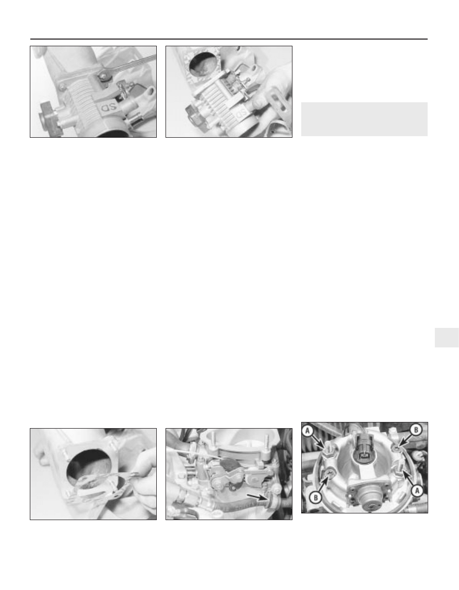
4B
10 Unscrew the four securing nuts, and
withdraw the throttle body from the inlet
manifold (see illustrations). Access to the
lower nuts is difficult and it may be necessary
to move the two fuel hoses to one side for
improved access. Take care not to strain the
hoses.
11 Recover the gasket.
12 If desired, the throttle position sensor can
be removed from the throttle body, with
reference to Section 23.
Refitting
13 Refitting is a reversal of removal,
remembering the following points.
14 Where applicable, refit the throttle
position sensor, as described in Section 23.
15 Refit the throttle body, using a new gasket
(see illustration).
16 Ensure that all hoses and wires are
correctly reconnected and routed.
17 Check and if necessary top-up the
coolant level, as described in Chapter 3.
18 Check and if necessary adjust the throttle
cable free play, as described in Section 19.
DOHC
Removal
19 Disconnect the battery negative lead.
20 Loosen the clamp screw securing the air
trunking to the left-hand side of the air mass
meter.
21 Using an Allen key or hexagon bit,
unscrew the four bolts securing the air box to
the throttle body. Lift the air box from the
throttle body, and disconnect the hose from
the base of the air box, then withdraw the air
box.
22 Disconnect the wiring plug from the
throttle position sensor.
23 Unscrew the retaining nut, and remove
the fuel hose bracket from the left-hand side
of the throttle body (see illustration).
24 Slide the throttle cable end from the
throttle valve lever.
25 Disconnect the breather hose from the
front of the throttle body.
26 Disconnect the vacuum pipe from the top
of the fuel pressure regulator.
27 Make a final check to ensure that all
relevant hoses, pipes and wires have been
disconnected and moved clear of the throttle
body.
28 Unscrew the four securing nuts, and
withdraw the throttle body from the inlet
manifold. Recover the gasket.
29 If desired, the throttle position sensor can
be removed from the throttle body, referring
to Section 31, if necessary.
30 Do not under any circumstances attempt
to adjust the throttle valve linkage. If the
throttle valve linkage is faulty, refer the
problem to a Vauxhall dealer.
Refitting
31 Refitting is a reversal of removal,
remembering the following points.
32 Where applicable, refit the throttle
position sensor, as described in Section 23.
33 Refit the throttle body, using a new
gasket.
34 Ensure that all hoses, pipes and wires are
correctly reconnected and routed.
35 On completion, check and if necessary
adjust the throttle cable free play, as
described in Section 19.
32 Throttle body (Multec
system) - removal and refitting
3
Removal
1 Depressurise the fuel system (Section 8).
2 Remove the air box (see above).
3 Disconnect the battery negative lead.
4 Disconnect the wiring plugs from the fuel
injector (pressing out the wiring rubber
grommet), from the idle air control stepper
motor and from the potentiometer.
5 Disconnect the fuel hoses from their unions
and plug them to prevent loss of fuel and the
entry of dirt; label them to ensure correct
refitting. Be prepared for fuel spillage and take
safety precautions.
6 Disconnect the vacuum hoses and pipes
from the body unions.
7 Disconnect the throttle valve operating
linkage at the throttle body.
8 Undo the two nuts securing the throttle
body to the inlet manifold and withdraw the
body assembly; peel off and discard the
gasket (see illustration).
9 If required, the throttle body’s upper and
lower sections may be separated by removing
the two Torx-type securing screws; note that
a new gasket must be fitted on reassembly.
The fuel inlet and return unions may also be
unscrewed, but note that new sealing rings
must be fitted on reassembly, and the unions
must be tightened securely.
Refitting
10 Refitting is the reverse of the removal
procedure, noting the following points (see
illustration).
a) Renew all gaskets and seals, and use
thread-locking compound where
applicable.
Fuel and exhaust systems - fuel injection models 4B•15
31.15 Refit the throttle body, using a new
gasket
32.8 Throttle body - Multec systems
A Mounting nuts
B Upper-to-lower section Torx screws
31.23 Remove the fuel hose bracket
(arrowed) from the throttle body -
DOHC models
31.10B. . . and withdraw the throttle body
(inlet manifold removed for clarity) -
SOHC models
31.10A Unscrew the securing nuts . . .
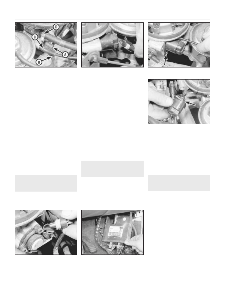
b) Check the throttle cable operation and
adjustment (see above).
c) When reconnecting the vacuum hoses
and pipes, ensure that they are connected
to the front unions as shown in the
accompanying photograph.
d) As no fuel vapour trap is fitted, it is
essential that the manifold absolute
pressure sensor vacuum hose is routed
so that it falls steadily from the sensor to
the throttle body. This precaution will
prevent any fuel droplets being trapped in
the sensor or hose and allowing them to
drain into the inlet port.
e) Ensure that the fuel hoses are correctly
reconnected; the feed hose is on the
injector end of the throttle body.
f) Switch on the ignition and check for signs
of fuel leaks from all disturbed unions; if
any signs of leakage are detected, the
problem must be rectified before the
engine is started.
33 Idle air control stepper
motor - removal and refitting
3
Removal
1 Remove the air box (see Section 5).
2 Disconnect the battery earth lead.
3 Disconnect the wiring plug from the stepper
motor (see illustration).
4 Undo its two screws, then withdraw the
stepper motor. Remove and discard the
sealing ring (see illustrations).
Refitting
5 Refitting is the reverse of the removal
procedure, noting the following points.
a) Fit a new sealing ring, greasing it lightly to
ease installation.
b) To prevent the risk of damage, either to
the throttle body or to the stepper motor,
if the motor’s plunger tip projects more
than 28 mm (1.1 in) beyond the motor’s
mating surface, carefully press the
plunger in until its stop is reached. The
stepper motor will then be reset by the
ECU when the engine is restarted.
c) Apply a few drops of a thread-locking
compound to their threads, then carefully
tighten the screws to the specified torque
wrench setting.
34 Throttle potentiometer -
removal and refitting
3
Removal
1 Disconnect the battery negative lead.
2 Disconnect the wiring plug from the
potentiometer
(see illustration).
3 Unscrew the two Torx-type securing
screws (size TX 25) and withdraw the
potentiometer.
Refitting
4 Refitting is the reverse of the removal
procedure, noting the following points.
a) Install the potentiometer when the throttle
valve is fully closed, and ensure that its
adapter seats correctly on the throttle
valve spindle.
b) Tighten the screws carefully to the
specified torque.
35 Electronic Control Unit
(ECU) - removal and refitting
3
Removal
1 Disconnect the battery negative lead.
2 Remove the driver’s footwell side trim panel
(Chapter 11).
3 Release the unit from its mountings and
withdraw it until the wiring plugs’ locking lugs
can be released and the plugs can be
disconnected (see illustration).
4 Note that the unit consists of two parts the
basic control unit and the Programmable
Read Only Memory (PROM). While it is
possible to renew them separately, do not
attempt to separate them. Faults requiring this
degree of attention can be diagnosed only by
an experienced mechanic using the special
Vauxhall test equipment. A previously sound
ECU could be seriously damaged by careless
handling of the contacts between the two
sub-units.
4B•16 Fuel and exhaust systems - fuel injection models
32.10 Intake air temperature control -
Multec systems
A Vacuum pipe
B Exhaust gas recirculation valve hose
C Charcoal canister control pipe
D Fuel return hose
33.4A Unscrew retaining screws (second
screw arrowed) . . .
35.3 Withdrawing the fuel
injection/ignition system ECU
34.2 Disconnecting the throttle
potentiometer wiring plug - note the
mounting screws (arrowed)
33.4B . . . to remove the stepper motor -
renew sealing ring (arrowed)
33.3 Disconnecting the idle air control
stepper motor wiring plug
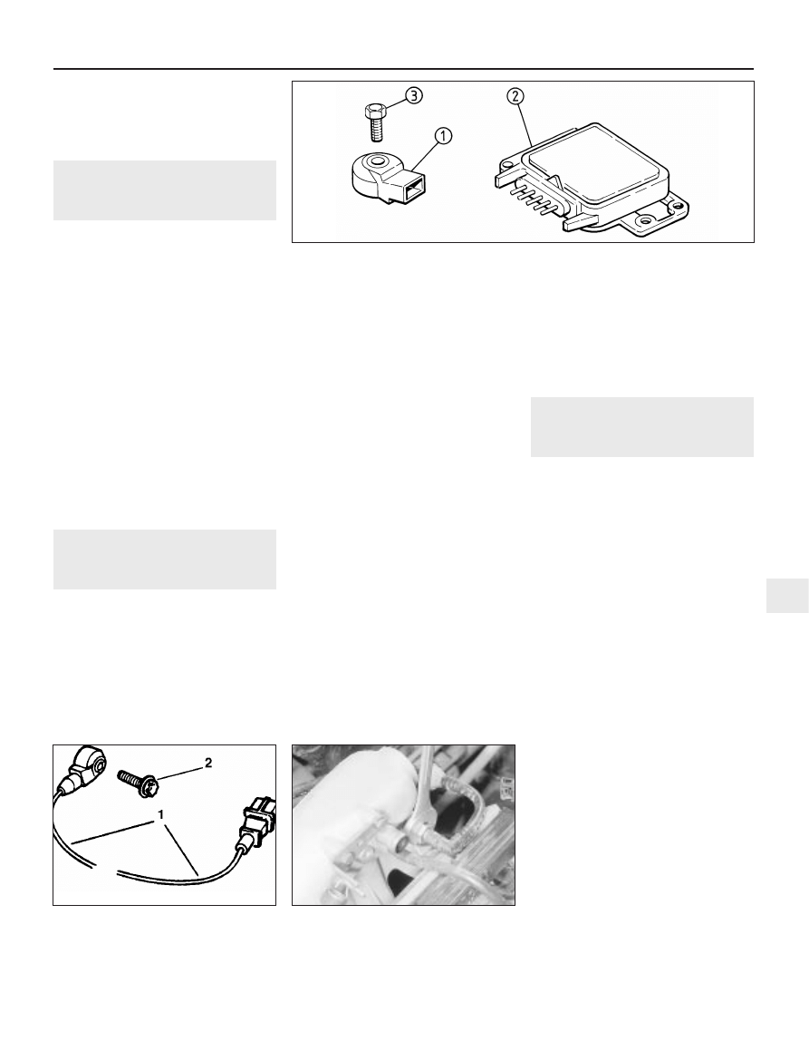
Refitting
5 Refitting is a reversal of the removal
procedure, ensuring that the wiring plugs are
correctly reconnected and that the unit is
located securely.
36 Knock sensor and module
(X16 SZ models) - removal
and refitting
3
Removal
1 The knock sensor fitted to the X16 SZ
engine is located on the cylinder block below
the inlet manifold, between cylinders 2 and 3.
2 Disconnect the battery negative lead.
3 Remove the wiring and unscrew the unit
from the block.
4 The module and control unit are located on
the left-hand side of the engine compartment
behind the battery. To remove, disconnect the
wiring multiplug and remove the retaining
bolts (see illustration).
5 There is no provision for testing the knock
sensor or module without dedicated Vauxhall
test equipment. Check for external damage
and replace if necessary.
Refitting
6 Refitting is a reversal of the removal
procedure, ensuring that the wiring plugs are
correctly reconnected and that the units are
located securely.
37 Knock sensor (Simtec
system) - removal and refitting
3
Removal
1 Disconnect the battery negative lead.
2 Disconnect wiring harness plug, from inlet
air temperature sensor and wiring harness
plug, from hot mass air flow meter.
3 Remove crankcase ventilation hoses.
4 Remove coolant hoses from air inlet hoses,
hot film mass air flow meter complete with air
inlet hoses, from upper part of air cleaner and
throttle body.
5 Press retaining clip for 1st and 4th cylinder
injectors in plug strip (with screwdriver)
towards fuel distributor pipe - lifting plug strip
at the same time. On the underside of the plug
strip there are a total of 6 plug connections, 4
of which are for the injectors.
6 Disconnect wiring harness plug for knock
sensor from the plug strip.
7 Connect a 1 metre length of separate cable
to knock sensor wiring harness plug (note
routing).
8 Remove knock sensor from cylinder block
(see illustration).
9 Disconnect knock sensor cable from
separately attached cable, separate cable
remains in engine compartment.
Refitting
10 Refitting is a reversal of removal, but note
the following.
11 Before refitting ensure that the sensor is
spotlessly clean. Clean the entire contact
surface of the sensor must lie directly on the
cylinder block. Do not use any form of
washers.
12 Carefully refit sensor into the block.
Tighten to the correct torque.
13 Guide knock sensor cable between ridges
on inlet manifold using separate cable -
ensure correct routing.
14 Remove the cable.
15 Insert the wiring harness plug for the
knock sensor, into the plug strip.
16 Correctly align the spring clips for the
injectors as they may prevent engagement of
the plug strip. Correct contact between the
plug strip and the injector is essential.
17 When connecting plug strip, an audible
‘click’ should be heard.
18 Ensure that hoses are in good condition
and installed securely with the two clamps.
38 Inlet manifold (SOHC without
Multec) - removal and refitting
3
Note: Refer to warning in Section 2, before
proceeding. Use a new gaskets when refitting.
Removal
1 Disconnect the battery negative lead.
2 Remove the idle speed adjuster and its
hoses, referring to Section 22, if necessary.
3 Release the securing clip, then disconnect
the throttle cable and balljoint from the throttle
valve lever. Slide the throttle cable grommet
from the bracket on the inlet manifold, and
move the throttle cable to one side out of the
way.
4 Loosen the clamp screw and disconnect
the air trunking from the throttle body.
5 Unscrew the union nut and disconnect the
brake servo vacuum hose from the inlet
manifold (see illustration).
6 Disconnect the camshaft cover breather
hose from the throttle body.
7 Disconnect the coolant hoses from the
throttle body. Be prepared for coolant
spillage, and clamp or plug the open ends of
the hoses, to prevent further coolant loss.
8 Disconnect the wiring plug from the throttle
position sensor.
9 Disconnect the vacuum pipe from the top
of the fuel pressure regulator.
10 Disconnect the wiring harness housing
from the fuel injectors and move it to one side,
taking care not to strain the wiring. Pull up on
the wiring harness housing, and compress the
wiring plug retaining clips to release the
harness housing from the injectors.
11 Disconnect the fuel hoses from the fuel
rail. Be prepared for fuel spillage, and take
adequate fire precautions. Clamp or plug the
open ends of the hoses, to prevent dirt
ingress and further fuel leakage.
Fuel and exhaust systems - fuel injection models 4B•17
38.5 Disconnecting the brake servo
vacuum hose -
SOHC models
37.8 Knock sensor and wiring
(Simtec system)
1 Sensor
2 Securing bolt
36.4 Knock sensor and module (X16 SZ models)
1 Sensor
2 Module
3 Sensor securing bolt
4B
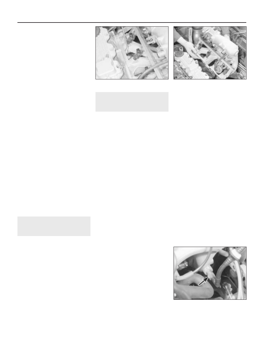
12 Unscrew and remove the top alternator
mounting nut and bolt.
13 Make a final check to ensure that all
relevant hoses, pipes and wires have been
disconnected.
14 Unscrew the securing nuts, and withdraw
the manifold from the cylinder head. Recover
the gasket (see illustrations).
15 It is possible that some of the manifold
studs may be unscrewed from the cylinder
head when the manifold securing nuts are
unscrewed. In this event, the studs should be
screwed back into the cylinder head once the
manifold has been removed, using two
manifold nuts locked together.
16 If desired, the ancillary components can
be removed from the manifold, referring to the
relevant Chapter.
Refitting
17 Refitting is a reversal of removal,
remembering the following points.
18 Where applicable refit any ancillary
components to the manifold, with reference to
relevant Sections of Chapters 4A or 4B.
19 If the alternator mounting bracket has
been unbolted from the manifold, refit it
before refitting the manifold, as access to the
securing bolt is extremely limited once the
manifold is in place.
20 Refit the manifold using a new gasket,
and tighten the securing nuts to the specified
torque.
21 Ensure that all relevant hoses, pipes and
wires are correctly reconnected.
22 On completion, check and if necessary
top-up the coolant level, (Chapter 3).
23 Check and if necessary adjust the throttle
cable free play, as described in Chapters 4A
or 4B, as applicable.
24 If any of the fuel system components have
been disturbed or renewed, check and if
necessary adjust the idle mixture, as
described in Chapters 4A or 4B, as applicable.
39 Inlet manifold (SOHC with
Multec) - removal and refitting
3
Removal
1 Depressurise the fuel system Section 8).
2 Remove the air box (see Section 5).
3 Disconnect the battery negative lead.
4 Either remove the throttle body assembly
(see Section 32), or disconnect the throttle
cable, wiring, fuel and vacuum hoses and
pipes to allow the manifold to be removed
with the throttle body.
5 Drain the cooling system (see Chapter 3).
6 Continue as described in Chapter 4A,
Section 26, paragraph 4 onwards.
Refitting
7 Refitting is the reverse of the removal
procedure; renew all gaskets and seals
disturbed.
40 Inlet manifold (DOHC
models) - removal and
refitting
3
Removal
1 Disconnect the battery negative lead.
2 Disconnect the wiring plug from the air
mass meter. Recover the sealing ring.
3 Loosen the clamp screw securing the air
trunking to the right-hand end of the air mass
meter.
4 Using an Allen key or hexagon bit, unscrew
the four bolts securing the air box to the
throttle body. Lift the air box from the throttle
body, and disconnect the hose from the base
of the air box then withdraw the air box/air
mass meter assembly.
5 Disconnect the wiring plug from the throttle
position sensor.
6 Slide the throttle cable end from the throttle
valve lever. Then pull the cable end grommet
from the bracket on the inlet manifold and
move the throttle cable to one side out of the
way.
7 Disconnect the two breather hoses from the
rear of the camshaft cover. Disconnect the
larger hose from the throttle body, and
remove the hose completely.
8 Position a wad of rag beneath one of the
fuel hose unions on the fuel rail, to absorb the
fuel that will be released as the union is
disconnected.
9 Slowly loosen the fuel hose union, to
gradually relieve the pressure in the fuel feed
line, then disconnect the hose from the fuel
rail. Be prepared for fuel spillage, and take
adequate fire precautions. Plug the end of the
fuel hose, to prevent dirt ingress and further
fuel leakage.
10 Repeat paragraphs 9 and 10 for the
remaining fuel hose-to-fuel rail union.
11 Disconnect the vacuum pipe from the top
of the fuel pressure regulator.
12 Disconnect the wiring harness housing
from the fuel injectors and move it to one side,
taking care not to strain the wiring. Pull up on
the wiring harness housing, and compress the
wiring plug retaining clips to release the
housing from the injectors.
13 Unscrew the union nut, and disconnect
the brake servo vacuum hose from the left-
hand side of the inlet manifold (see
illustration).
14 Unscrew the retaining nut, and remove
the fuel hose bracket from the left-hand side
of the throttle body.
15 Unscrew the securing nuts, and
disconnect the earth leads from the fuel rail
securing studs at either end of the fuel rail.
16 Unscrew the securing bolt, and remove
the cable/hose bracket from the left-hand end
of the inlet manifold.
17 Remove the idle speed adjuster, as
described in Section 22.
18 Unscrew and remove the top alternator
mounting nut and bolt.
19 Make a final check to ensure that all
relevant hoses, pipes and wires have been
disconnected.
20 Unscrew the securing nuts, and withdraw
the manifold from the cylinder head. Recover
the gasket.
21 It is possible that some of the manifold
studs may be unscrewed from the cylinder
head when the manifold securing nuts are
unscrewed. In this event, the studs should be
screwed back into the cylinder head once the
manifold has been removed, using two
manifold nuts locked together.
22 If desired, the ancillary components can
be removed from the manifold, with reference
to the relevant Sections of Chapters 4A or 4B.
Refitting
23 Refitting is a reversal of the removal
procedure.
4B•18 Fuel and exhaust systems - fuel injection models
38.14A Unscrew the securing nuts
40.13 Brake servo vacuum hose
connection at inlet manifold (arrowed) -
DOHC models
38.14B ...and withdraw the inlet manifold -
SOHC models
Wyszukiwarka
Podobne podstrony:
Matematyka PG PP kl2 MPZ sprawdzian 04B arkusz
1570 04C
elektro wyklad 04b
1570
PR1 04b
04b RACHUNEK ZYSKÓW I STRAT
30 A 1570 r 1600 r renesans, manieryzm
1570 Pius V Quo primum tempore
04b BUDOWA CIALA STALEGOid 53 Nieznany (2)
1998 07 17 1570
0656PWsrTz1 Rysunek 04b
FIG-04B
miernictwo 04b oscyloskop ox 800
Matematyka PG PP kl2 MPZ sprawdzian 04B instrukcja
04b harmonogram spotkan, awans zawodowy
1570
więcej podobnych podstron