
I
Executable and Linkable Format (ELF)

Contents
Preface
1
OBJECT FILES
Introduction
1-1
ELF Header
1-3
Sections
1-8
String Table
1-16
Symbol Table
1-17
Relocation
1-21
2
PROGRAM LOADING AND DYNAMIC LINKING
Introduction
2-1
Program Header
2-2
Program Loading
2-7
Dynamic Linking
2-10
3
C LIBRARY
C Library
3-1
I
Index
Index
I-1
Tool Interface Standards (TIS)
Portable Formats Specification, Version 1.1
i

ELF: Executable and Linkable Format
ii
Portable Formats Specification, Version 1.1
Tool Interface Standards (TIS)

Figures and Tables
Figure 1-1: Object File Format
1-1
Figure 1-2: 32-Bit Data Types
1-2
Figure 1-3: ELF Header
1-3
Figure 1-4:
e
_
i
d
e
n
t
[ ]
Identification Indexes
1-5
Figure 1-5: Data Encoding
E
L
F
D
A
T
A
2
L
S
B
1-6
Figure 1-6: Data Encoding
E
L
F
D
A
T
A
2
M
S
B
1-6
Figure 1-7: 32-bit Intel Architecture Identification,
e
_
i
d
e
n
t
1-7
Figure 1-8: Special Section Indexes
1-8
Figure 1-9: Section Header
1-9
Figure 1-10: Section Types,
s
h
_
t
y
p
e
1-10
Figure 1-11: Section Header Table Entry: Index 0
1-11
Figure 1-12: Section Attribute Flags,
s
h
_
f
l
a
g
s
1-12
Figure 1-13:
s
h
_
l
i
n
k
and
s
h
_
i
n
f
o
Interpretation 1-13
Figure 1-14: Special Sections
1-13
Figure 1-15: String Table Indexes
1-16
Figure 1-16: Symbol Table Entry
1-17
Figure 1-17: Symbol Binding,
E
L
F
3
2
_
S
T
_
B
I
N
D
1-18
Figure 1-18: Symbol Types,
E
L
F
3
2
_
S
T
_
T
Y
P
E
1-19
Figure 1-19: Symbol Table Entry: Index 0
1-20
Figure 1-20: Relocation Entries
1-21
Figure 1-21: Relocatable Fields
1-22
Figure 1-22: Relocation Types
1-23
Figure 2-1: Program Header
2-2
Figure 2-2: Segment Types,
p
_
t
y
p
e
2-3
Figure 2-3: Note Information
2-4
Figure 2-4: Example Note Segment
2-5
Figure 2-5: Executable File
2-7
Figure 2-6: Program Header Segments
2-7
Figure 2-7: Process Image Segments
2-8
Figure 2-8: Example Shared Object Segment Addresses
2-9
Figure 2-9: Dynamic Structure
2-12
Figure 2-10: Dynamic Array Tags,
d
_
t
a
g
2-12
Figure 2-11: Global Offset Table
2-17
Figure 2-12: Absolute Procedure Linkage Table
2-17
Figure 2-13: Position-Independent Procedure Linkage Table
2-18
Figure 2-14: Symbol Hash Table
2-19
Figure 2-15: Hashing Function
2-20
Figure 3-1:
l
i
b
c
Contents, Names without Synonyms
3-1
Figure 3-2:
l
i
b
c
Contents, Names with Synonyms
3-1
Figure 3-3:
l
i
b
c
Contents, Global External Data Symbols
3-2
Tool Interface Standards (TIS)
Portable Formats Specification, Version 1.1
iii
Preface
ELF: Executable and Linking Format
The Executable and Linking Format was originally developed and published by UNIX System Labora-
tories (USL) as part of the Application Binary Interface (ABI). The Tool Interface Standards committee
(TIS) has selected the evolving ELF standard as a portable object file format that works on 32-bit Intel
Architecture environments for a variety of operating systems.
The ELF standard is intended to streamline software development by providing developers with a set of
binary interface definitions that extend across multiple operating environments. This should reduce the
number of different interface implementations, thereby reducing the need for recoding and recompiling
code.
About This Document
This document is intended for developers who are creating object or executable files on various 32-bit
environment operating systems. It is divided into the following three parts:
Part 1, ‘‘Object Files’’ describes the ELF object file format for the three main types of object files.
Part 2, ‘‘Program Loading and Dynamic Linking’’ describes the object file information and system
actions that create running programs.
Part 3, ‘‘C Library’’ lists the symbols contained in
l
i
b
s
y
s
, the standard ANSI C and
l
i
b
c
routines,
and the global data symbols required by the
l
i
b
c
routines.
NOTE
References to X86 architecture have been changed to Intel Architecture.
Tool Interface Standards (TIS)
Portable Formats Specification, Version 1.1
1

1
OBJECT FILES
Introduction
1-1
File Format
1-1
Data Representation
1-2
ELF Header
1-3
ELF Identification
1-5
Machine Information
1-7
Sections
1-8
Special Sections
1-13
String Table
1-16
Symbol Table
1-17
Symbol Values
1-20
Relocation
1-21
Relocation Types
1-22
Tool Interface Standards (TIS)
Portable Formats Specification, Version 1.1
i

Introduction
Part 1 describes the iABI object file format, called ELF (Executable and Linking Format). There are three
main types of object files.
A relocatable file holds code and data suitable for linking with other object files to create an execut-
able or a shared object file.
An executable file holds a program suitable for execution; the file specifies how
e
x
e
c
(BA
_
OS) creates
a program’s process image.
A shared object file holds code and data suitable for linking in two contexts. First, the link editor [see
l
d
(SD
_
CMD)] may process it with other relocatable and shared object files to create another object
file. Second, the dynamic linker combines it with an executable file and other shared objects to
create a process image.
Created by the assembler and link editor, object files are binary representations of programs intended to
execute directly on a processor. Programs that require other abstract machines, such as shell scripts, are
excluded.
After the introductory material, Part 1 focuses on the file format and how it pertains to building pro-
grams. Part 2 also describes parts of the object file, concentrating on the information necessary to execute
a program.
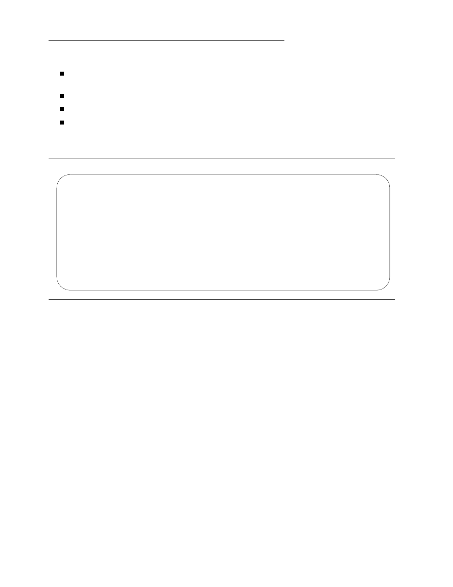
File Format
Object files participate in program linking (building a program) and program execution (running a pro-
gram). For convenience and efficiency, the object file format provides parallel views of a file’s contents,
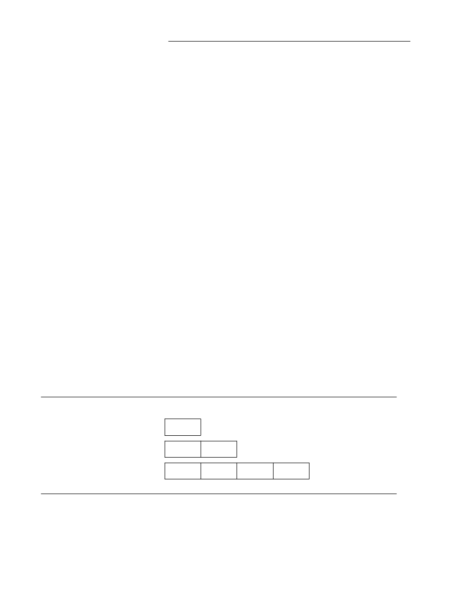
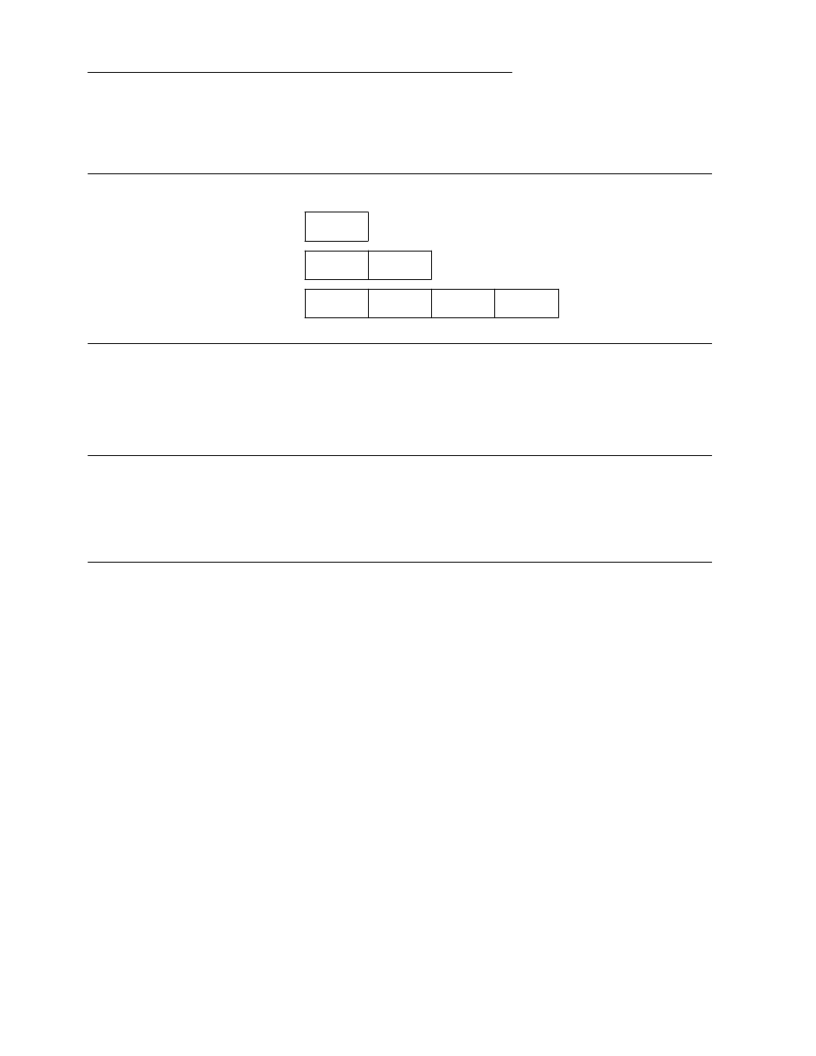
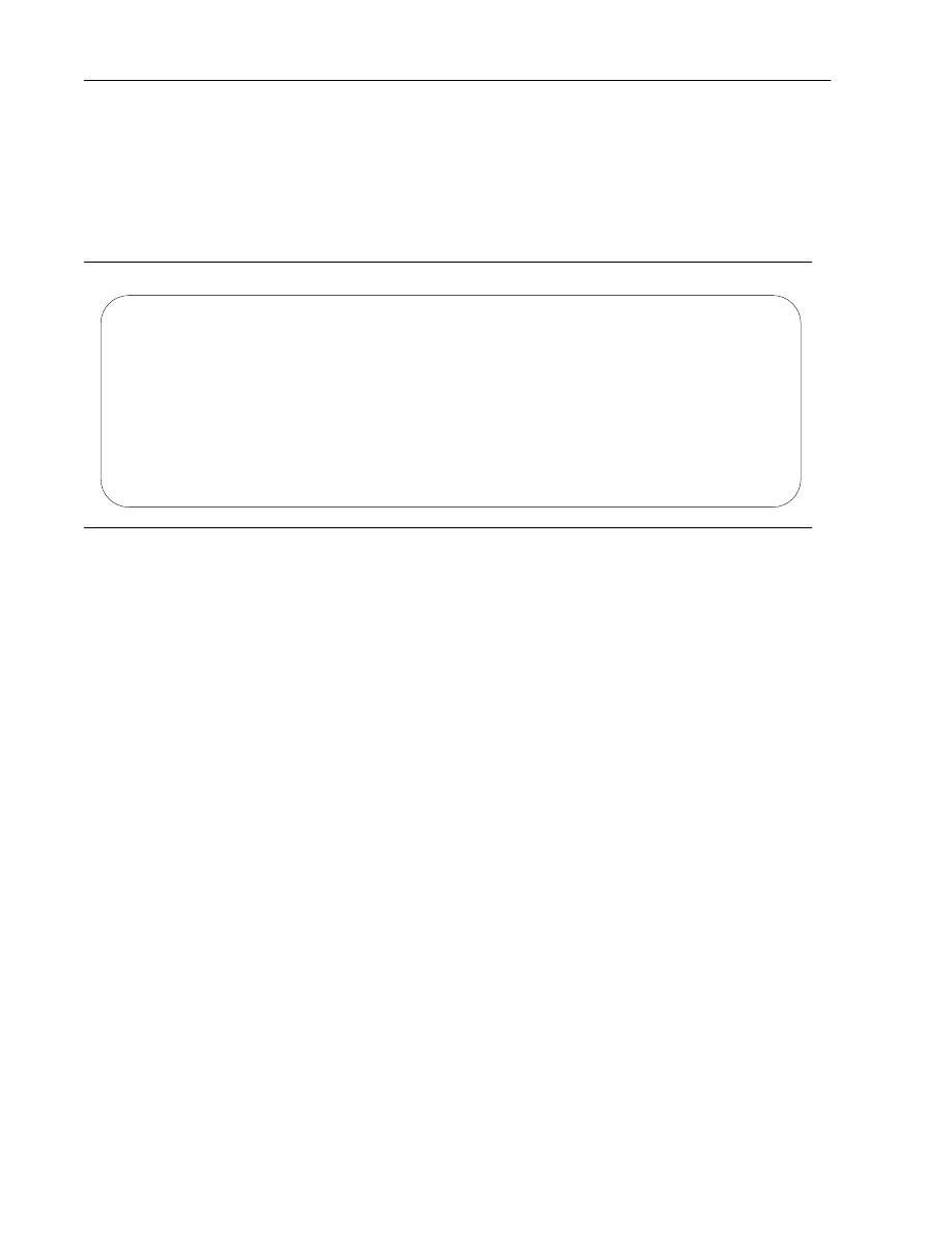
reflecting the differing needs of these activities. Figure 1-1 shows an object file’s organization.
Figure 1-1: Object File Format
Linking View
Execution View
_ _____________________ _
______________________
ELF header
ELF header
_ _____________________ _
______________________
Program header table
Program header table
optional
_ _____________________ _
______________________
Section 1
_ _____________________
. . .
Segment 1
_ _____________________ _
______________________
Section n
_ _____________________
. . .
Segment 2
_ _____________________ _
______________________
. . .
. . .
_ _____________________ _
______________________
Section header table
Section header table
optional
_ _____________________ _
______________________
An ELF header resides at the beginning and holds a ‘‘road map’’ describing the file’s organization. Sec-
tions hold the bulk of object file information for the linking view: instructions, data, symbol table, reloca-
tion information, and so on. Descriptions of special sections appear later in Part 1. Part 2 discusses seg-
ments and the program execution view of the file.
Tool Interface Standards (TIS)
Portable Formats Specification, Version 1.1
1-1

ELF: Executable and Linkable Format
A program header table, if present, tells the system how to create a process image. Files used to build a pro-
cess image (execute a program) must have a program header table; relocatable files do not need one. A
section header table contains information describing the file’s sections. Every section has an entry in the
table; each entry gives information such as the section name, the section size, etc. Files used during link-
ing must have a section header table; other object files may or may not have one.
NOTE
Although the figure shows the program header table immediately after the ELF header, and the section
header table following the sections, actual files may differ. Moreover, sections and segments have no
specified order. Only the ELF header has a fixed position in the file.
Data Representation
As described here, the object file format supports various processors with 8-bit bytes and 32-bit architec-
tures. Nevertheless, it is intended to be extensible to larger (or smaller) architectures. Object files there-
fore represent some control data with a machine-independent format, making it possible to identify
object files and interpret their contents in a common way. Remaining data in an object file use the encod-
ing of the target processor, regardless of the machine on which the file was created.
Figure 1-2: 32-Bit Data Types
Name Size
Alignment
Purpose
_ ____________________________________________________________
E
l
f
3
2
_
A
d
d
r
4
4
Unsigned program address
E
l
f
3
2
_
H
a
l
f
2
2
Unsigned medium integer
E
l
f
3
2
_
O
f
f
4 4
Unsigned
file offset
E
l
f
3
2
_
S
w
o
r
d
4
4
Signed large integer
E
l
f
3
2
_
W
o
r
d
4
4
Unsigned large integer
u
n
s
i
g
n
e
d c
h
a
r
1
1
Unsigned small integer
_ ____________________________________________________________
All data structures that the object file format defines follow the ‘‘natural’’ size and alignment guidelines
for the relevant class. If necessary, data structures contain explicit padding to ensure 4-byte alignment for
4-byte objects, to force structure sizes to a multiple of 4, etc. Data also have suitable alignment from the
beginning of the file. Thus, for example, a structure containing an
E
l
f
3
2
_
A
d
d
r
member will be aligned
on a 4-byte boundary within the file.
For portability reasons, ELF uses no bit-fields.
1-2
Portable Formats Specification, Version 1.1
Tool Interface Standards (TIS)

ELF Header
Some object file control structures can grow, because the ELF header contains their actual sizes. If the
object file format changes, a program may encounter control structures that are larger or smaller than
expected. Programs might therefore ignore ‘‘extra’’ information. The treatment of ‘‘missing’’ informa-
tion depends on context and will be specified when and if extensions are defined.
Figure 1-3: ELF Header
#
d
e
f
i
n
e E
I
_
N
I
D
E
N
T 1
6
t
y
p
e
d
e
f s
t
r
u
c
t {
u
n
s
i
g
n
e
d c
h
a
r e
_
i
d
e
n
t
[
E
I
_
N
I
D
E
N
T
]
;
E
l
f
3
2
_
H
a
l
f e
_
t
y
p
e
;
E
l
f
3
2
_
H
a
l
f e
_
m
a
c
h
i
n
e
;
E
l
f
3
2
_
W
o
r
d e
_
v
e
r
s
i
o
n
;
E
l
f
3
2
_
A
d
d
r e
_
e
n
t
r
y
;
E
l
f
3
2
_
O
f
f e
_
p
h
o
f
f
;
E
l
f
3
2
_
O
f
f e
_
s
h
o
f
f
;
E
l
f
3
2
_
W
o
r
d e
_
f
l
a
g
s
;
E
l
f
3
2
_
H
a
l
f e
_
e
h
s
i
z
e
;
E
l
f
3
2
_
H
a
l
f e
_
p
h
e
n
t
s
i
z
e
;
E
l
f
3
2
_
H
a
l
f e
_
p
h
n
u
m
;
E
l
f
3
2
_
H
a
l
f e
_
s
h
e
n
t
s
i
z
e
;
E
l
f
3
2
_
H
a
l
f e
_
s
h
n
u
m
;
E
l
f
3
2
_
H
a
l
f e
_
s
h
s
t
r
n
d
x
;
} E
l
f
3
2
_
E
h
d
r
;
e_ident
The initial bytes mark the file as an object file and provide machine-independent data
with which to decode and interpret the file’s contents. Complete descriptions appear
below, in ‘‘ELF Identification.’’
e_type
This member identifies the object file type.
Name Value Meaning
_ _______________________________________
ET_NONE 0
No file type
ET_REL 1
Relocatable file
ET_EXEC 2
Executable file
ET_DYN 3
Shared object file
ET_CORE 4
Core file
ET_LOPROC 0xff00
Processor-specific
ET_HIPROC 0xffff
Processor-specific
_ _______________________________________
Although the core file contents are unspecified, type
ET_CORE
is reserved to mark the
file. Values from
ET_LOPROC
through
ET_HIPROC
(inclusive) are reserved for
processor-specific semantics. Other values are reserved and will be assigned to new
object file types as necessary.
Tool Interface Standards (TIS)
Portable Formats Specification, Version 1.1
1-3

ELF: Executable and Linkable Format
e_machine
This member’s value specifies the required architecture for an individual file.
Name Value Meaning
_ ___________________________________
EM_NONE 0
No machine
EM_M32 1
AT&T WE 32100
EM_SPARC 2
SPARC
EM_386 3
Intel 80386
EM_68K 4
Motorola 68000
EM_88K 5
Motorola 88000
EM_860 7
Intel 80860
EM_MIPS 8
MIPS RS3000
_ ___________________________________
Other values are reserved and will be assigned to new machines as necessary.
Processor-specific ELF names use the machine name to distinguish them. For example,
the flags mentioned below use the prefix
EF_
; a flag named
WIDGET
for the
EM_XYZ
machine would be called
EF_XYZ_WIDGET
.
e_version
This member identifies the object file version.
Name Value Meaning
_ _____________________________________
EV_NONE 0
Invalid version
EV_CURRENT 1
Current version
_ _____________________________________
The value
1
signifies the original file format; extensions will create new versions with
higher numbers. The value of
EV_CURRENT
, though given as
1
above, will change as
necessary to reflect the current version number.
e_entry
This member gives the virtual address to which the system first transfers control, thus
starting the process. If the file has no associated entry point, this member holds zero.
e_phoff
This member holds the program header table’s file offset in bytes. If the file has no
program header table, this member holds zero.
e_shoff
This member holds the section header table’s file offset in bytes. If the file has no sec-
tion header table, this member holds zero.
e_flags
This member holds processor-specific flags associated with the file. Flag names take
the form
EF_
machine
_
flag. See ‘‘Machine Information’’ for flag definitions.
e_ehsize
This member holds the ELF header’s size in bytes.
e_phentsize
This member holds the size in bytes of one entry in the file’s program header table; all
entries are the same size.
e_phnum
This member holds the number of entries in the program header table. Thus the pro-
duct of
e_phentsize
and
e_phnum
gives the table’s size in bytes. If a file has no pro-
gram header table,
e_phnum
holds the value zero.
e_shentsize
This member holds a section header’s size in bytes. A section header is one entry in
the section header table; all entries are the same size.
e_shnum
This member holds the number of entries in the section header table. Thus the product
of
e_shentsize
and
e_shnum
gives the section header table’s size in bytes. If a file
has no section header table,
e_shnum
holds the value zero.
1-4
Portable Formats Specification, Version 1.1
Tool Interface Standards (TIS)

ELF: Executable and Linkable Format
e_shstrndx
This member holds the section header table index of the entry associated with the sec-
tion name string table. If the file has no section name string table, this member holds
the value
SHN_UNDEF
. See ‘‘Sections’’ and ‘‘String Table’’ below for more informa-
tion.
ELF Identification
As mentioned above, ELF provides an object file framework to support multiple processors, multiple data
encodings, and multiple classes of machines. To support this object file family, the initial bytes of the file
specify how to interpret the file, independent of the processor on which the inquiry is made and indepen-
dent of the file’s remaining contents.
The initial bytes of an ELF header (and an object file) correspond to the
e_ident
member.
Figure 1-4:
e_ident[ ]
Identification Indexes
Name Value
Purpose
_ __________________________________________
EI_MAG0 0
File identification
EI_MAG1 1
File identification
EI_MAG2 2
File identification
EI_MAG3 3
File identification
EI_CLASS 4
File class
EI_DATA 5
Data encoding
EI_VERSION 6
File version
EI_PAD 7
Start of padding bytes
EI_NIDENT 16
Size of
e_ident[]
_ __________________________________________
These indexes access bytes that hold the following values.
EI_MAG0
to
EI_MAG3
A file’s first 4 bytes hold a ‘‘magic number,’’ identifying the file as an ELF object file.
Name Value
Position
_ ______________________________________
ELFMAG0 0x7f e_ident[EI_MAG0]
ELFMAG1 ’E’ e_ident[EI_MAG1]
ELFMAG2 ’L’ e_ident[EI_MAG2]
ELFMAG3 ’F’ e_ident[EI_MAG3]
_ ______________________________________
EI_CLASS
The next byte,
e_ident[EI_CLASS]
, identifies the file’s class, or capacity.
Tool Interface Standards (TIS)
Portable Formats Specification, Version 1.1
1-5
ELF: Executable and Linkable Format
Name Value
Meaning
_
_____________________________________
ELFCLASSNONE 0
Invalid class
ELFCLASS32 1
32-bit objects
ELFCLASS64 2
64-bit objects
_
_____________________________________
The file format is designed to be portable among machines of various sizes, without
imposing the sizes of the largest machine on the smallest. Class
ELFCLASS32
supports
machines with files and virtual address spaces up to 4 gigabytes; it uses the basic types
defined above.
Class
ELFCLASS64
is reserved for 64-bit architectures. Its appearance here shows how
the object file may change, but the 64-bit format is otherwise unspecified. Other classes
will be defined as necessary, with different basic types and sizes for object file data.
EI_DATA
Byte
e_ident[EI_DATA]
specifies the data encoding of the processor-specific data in
the object file. The following encodings are currently defined.
Name Value Meaning
_ ___________________________________________
ELFDATANONE 0
Invalid data encoding
ELFDATA2LSB 1
See below
ELFDATA2MSB 2
See below
_ ___________________________________________
More information on these encodings appears below. Other values are reserved and
will be assigned to new encodings as necessary.
EI_VERSION
Byte
e_ident[EI_VERSION]
specifies the ELF header version number. Currently, this
value must be
EV_CURRENT
, as explained above for
e_version
.
EI_PAD
This value marks the beginning of the unused bytes in
e_ident
. These bytes are
reserved and set to zero; programs that read object files should ignore them. The value
of
EI_PAD
will change in the future if currently unused bytes are given meanings.
A file’s data encoding specifies how to interpret the basic objects in a file. As described above, class
ELFCLASS32
files use objects that occupy 1, 2, and 4 bytes. Under the defined encodings, objects are
represented as shown below. Byte numbers appear in the upper left corners.
Encoding
ELFDATA2LSB
specifies 2’s complement values, with the least significant byte occupying the
lowest address.
Figure 1-5: Data Encoding
ELFDATA2LSB
01
0
0x01
02
0
01
1
0x0102
04
0
03
1
02
2
01
3
0x01020304
1-6
Portable Formats Specification, Version 1.1
Tool Interface Standards (TIS)
ELF: Executable and Linkable Format
Encoding
ELFDATA2MSB
specifies 2’s complement values, with the most significant byte occupying the
lowest address.
Figure 1-6: Data Encoding
ELFDATA2MSB
01
0
0x01
01
0
02
1
0x0102
01
0
02
1
03
2
04
3
0x01020304
Machine Information
For file identification in
e_ident
, the 32-bit Intel Architecture requires the following values.
Figure 1-7: 32-bit Intel Architecture Identification,
e_ident
Position Value
_ ____________________________________
e_ident[EI_CLASS] ELFCLASS32
e_ident[EI_DATA] ELFDATA2LSB
_ ____________________________________
Processor identification resides in the ELF header’s
e_machine
member and must have the value
EM_386
.
The ELF header’s
e_flags
member holds bit flags associated with the file. The 32-bit Intel Architecture
defines no flags; so this member contains zero.
Tool Interface Standards (TIS)
Portable Formats Specification, Version 1.1
1-7
Sections
An object file’s section header table lets one locate all the file’s sections. The section header table is an
array of
Elf32_Shdr
structures as described below. A section header table index is a subscript into this
array. The ELF header’s
e_shoff
member gives the byte offset from the beginning of the file to the sec-
tion header table;
e_shnum
tells how many entries the section header table contains;
e_shentsize
gives the size in bytes of each entry.
Some section header table indexes are reserved; an object file will not have sections for these special
indexes.
Figure 1-8: Special Section Indexes
Name Value
_ _________________________
SHN_UNDEF 0
SHN_LORESERVE 0xff00
SHN_LOPROC 0xff00
SHN_HIPROC 0xff1f
SHN_ABS 0xfff1
SHN_COMMON 0xfff2
SHN_HIRESERVE 0xffff
_ _________________________
SHN_UNDEF
This value marks an undefined, missing, irrelevant, or otherwise meaningless section
reference. For example, a symbol ‘‘defined’’ relative to section number
SHN_UNDEF
is an undefined symbol.
NOTE
Although index 0 is reserved as the undefined value, the section header table contains an entry for
index 0. That is, if the
e_shnum
member of the ELF header says a file has 6 entries in the section
header table, they have the indexes 0 through 5. The contents of the initial entry are specified later in
this section.
SHN_LORESERVE
This value specifies the lower bound of the range of reserved indexes.
SHN_LOPROC
through
SHN_HIPROC
Values in this inclusive range are reserved for processor-specific semantics.
SHN_ABS
This value specifies absolute values for the corresponding reference. For example,
symbols defined relative to section number
SHN_ABS
have absolute values and are
not affected by relocation.
SHN_COMMON
Symbols defined relative to this section are common symbols, such as FORTRAN
COMMON
or unallocated C external variables.
SHN_HIRESERVE
This value specifies the upper bound of the range of reserved indexes. The system
reserves indexes between
SHN_LORESERVE
and
SHN_HIRESERVE
, inclusive; the
values do not reference the section header table. That is, the section header table
does not contain entries for the reserved indexes.
Sections contain all information in an object file, except the ELF header, the program header table, and the
section header table. Moreover, object files’ sections satisfy several conditions.
1-8
Portable Formats Specification, Version 1.1
Tool Interface Standards (TIS)
ELF: Executable and Linkable Format
Every section in an object file has exactly one section header describing it. Section headers may
exist that do not have a section.
Each section occupies one contiguous (possibly empty) sequence of bytes within a file.
Sections in a file may not overlap. No byte in a file resides in more than one section.
An object file may have inactive space. The various headers and the sections might not ‘‘cover’’
every byte in an object file. The contents of the inactive data are unspecified.
A section header has the following structure.
Figure 1-9: Section Header
t
y
p
e
d
e
f s
t
r
u
c
t {
E
l
f
3
2
_
W
o
r
d s
h
_
n
a
m
e
;
E
l
f
3
2
_
W
o
r
d s
h
_
t
y
p
e
;
E
l
f
3
2
_
W
o
r
d s
h
_
f
l
a
g
s
;
E
l
f
3
2
_
A
d
d
r s
h
_
a
d
d
r
;
E
l
f
3
2
_
O
f
f s
h
_
o
f
f
s
e
t
;
E
l
f
3
2
_
W
o
r
d s
h
_
s
i
z
e
;
E
l
f
3
2
_
W
o
r
d s
h
_
l
i
n
k
;
E
l
f
3
2
_
W
o
r
d s
h
_
i
n
f
o
;
E
l
f
3
2
_
W
o
r
d s
h
_
a
d
d
r
a
l
i
g
n
;
E
l
f
3
2
_
W
o
r
d s
h
_
e
n
t
s
i
z
e
;
} E
l
f
3
2
_
S
h
d
r
;
sh_name
This member specifies the name of the section. Its value is an index into the section
header string table section [see ‘‘String Table’’ below], giving the location of a null-
terminated string.
sh_type
This member categorizes the section’s contents and semantics. Section types and their
descriptions appear below.
sh_flags
Sections support 1-bit flags that describe miscellaneous attributes. Flag definitions
appear below.
sh_addr
If the section will appear in the memory image of a process, this member gives the
address at which the section’s first byte should reside. Otherwise, the member con-
tains 0.
sh_offset
This member’s value gives the byte offset from the beginning of the file to the first
byte in the section. One section type,
SHT_NOBITS
described below, occupies no
space in the file, and its
sh_offset
member locates the conceptual placement in the
file.
sh_size
This member gives the section’s size in bytes. Unless the section type is
SHT_NOBITS
, the section occupies
sh_size
bytes in the file. A section of type
SHT_NOBITS
may have a non-zero size, but it occupies no space in the file.
sh_link
This member holds a section header table index link, whose interpretation depends
on the section type. A table below describes the values.
Tool Interface Standards (TIS)
Portable Formats Specification, Version 1.1
1-9

ELF: Executable and Linkable Format
sh_info
This member holds extra information, whose interpretation depends on the section
type. A table below describes the values.
sh_addralign
Some sections have address alignment constraints. For example, if a section holds a
doubleword, the system must ensure doubleword alignment for the entire section.
That is, the value of
sh_addr
must be congruent to 0, modulo the value of
sh_addralign
. Currently, only 0 and positive integral powers of two are allowed.
Values 0 and 1 mean the section has no alignment constraints.
sh_entsize
Some sections hold a table of fixed-size entries, such as a symbol table. For such a sec-
tion, this member gives the size in bytes of each entry. The member contains 0 if the
section does not hold a table of fixed-size entries.
A section header’s
sh_type
member specifies the section’s semantics.
Figure 1-10: Section Types,
sh_type
Name Value
_ _____________________________
SHT_NULL 0
SHT_PROGBITS 1
SHT_SYMTAB 2
SHT_STRTAB 3
SHT_RELA 4
SHT_HASH 5
SHT_DYNAMIC 6
SHT_NOTE 7
SHT_NOBITS 8
SHT_REL 9
SHT_SHLIB 10
SHT_DYNSYM 11
SHT_LOPROC 0x70000000
SHT_HIPROC 0x7fffffff
SHT_LOUSER 0x80000000
SHT_HIUSER 0xffffffff
_ _____________________________
SHT_NULL
This value marks the section header as inactive; it does not have an associated section.
Other members of the section header have undefined values.
SHT_PROGBITS
The section holds information defined by the program, whose format and meaning are
determined solely by the program.
SHT_SYMTAB
and
SHT_DYNSYM
These sections hold a symbol table. Currently, an object file may have only one sec-
tion of each type, but this restriction may be relaxed in the future. Typically,
SHT_SYMTAB
provides symbols for link editing, though it may also be used for
dynamic linking. As a complete symbol table, it may contain many symbols unneces-
sary for dynamic linking. Consequently, an object file may also contain a
SHT_DYNSYM
section, which holds a minimal set of dynamic linking symbols, to save
space. See ‘‘Symbol Table’’ below for details.
1-10
Portable Formats Specification, Version 1.1
Tool Interface Standards (TIS)

ELF: Executable and Linkable Format
SHT_STRTAB
The section holds a string table. An object file may have multiple string table sections.
See ‘‘String Table’’ below for details.
SHT_RELA
The section holds relocation entries with explicit addends, such as type
Elf32_Rela
for the 32-bit class of object files. An object file may have multiple relocation sections.
See ‘‘Relocation’’ below for details.
SHT_HASH
The section holds a symbol hash table. All objects participating in dynamic linking
must contain a symbol hash table. Currently, an object file may have only one hash
table, but this restriction may be relaxed in the future. See ‘‘Hash Table’’ in Part 2 for
details.
SHT_DYNAMIC
The section holds information for dynamic linking. Currently, an object file may have
only one dynamic section, but this restriction may be relaxed in the future. See
‘‘Dynamic Section’’ in Part 2 for details.
SHT_NOTE
The section holds information that marks the file in some way. See ‘‘Note Section’’ in
Part 2 for details.
SHT_NOBITS
A section of this type occupies no space in the file but otherwise resembles
SHT_PROGBITS
. Although this section contains no bytes, the
sh_offset
member
contains the conceptual file offset.
SHT_REL
The section holds relocation entries without explicit addends, such as type
Elf32_Rel
for the 32-bit class of object files. An object file may have multiple reloca-
tion sections. See ‘‘Relocation’’ below for details.
SHT_SHLIB
This section type is reserved but has unspecified semantics. Programs that contain a
section of this type do not conform to the ABI.
SHT_LOPROC
through
SHT_HIPROC
Values in this inclusive range are reserved for processor-specific semantics.
SHT_LOUSER
This value specifies the lower bound of the range of indexes reserved for application
programs.
SHT_HIUSER
This value specifies the upper bound of the range of indexes reserved for application
programs. Section types between
SHT_LOUSER
and
SHT_HIUSER
may be used by
the application, without conflicting with current or future system-defined section
types.
Other section type values are reserved. As mentioned before, the section header for index 0
(
SHN_UNDEF
) exists, even though the index marks undefined section references. This entry holds the fol-
lowing.
Figure 1-11: Section Header Table Entry: Index 0
Name Value
Note
_ _____________________________________________________
sh_name 0
No name
sh_type SHT_NULL
Inactive
sh_flags 0
No flags
sh_addr 0
No address
sh_offset 0
No file offset
sh_size 0
No size
Tool Interface Standards (TIS)
Portable Formats Specification, Version 1.1
1-11

ELF: Executable and Linkable Format
Figure 1-11: Section Header Table Entry: Index 0 (continued )
sh_link SHN_UNDEF
No link information
sh_info 0
No auxiliary information
sh_addralign 0
No alignment
sh_entsize 0
No entries
_ _____________________________________________________
A section header’s
sh_flags
member holds 1-bit flags that describe the section’s attributes. Defined
values appear below; other values are reserved.
Figure 1-12: Section Attribute Flags,
sh_flags
Name Value
_ ______________________________
SHF_WRITE 0x1
SHF_ALLOC 0x2
SHF_EXECINSTR 0x4
SHF_MASKPROC 0xf0000000
_ ______________________________
If a flag bit is set in
sh_flags
, the attribute is ‘‘on’’ for the section. Otherwise, the attribute is ‘‘off’’ or
does not apply. Undefined attributes are set to zero.
SHF_WRITE
The section contains data that should be writable during process execution.
SHF_ALLOC
The section occupies memory during process execution. Some control sections do
not reside in the memory image of an object file; this attribute is off for those sections.
SHF_EXECINSTR
The section contains executable machine instructions.
SHF_MASKPROC
All bits included in this mask are reserved for processor-specific semantics.
Two members in the section header,
sh_link
and
sh_info
, hold special information, depending on
section type.
1-12
Portable Formats Specification, Version 1.1
Tool Interface Standards (TIS)

ELF: Executable and Linkable Format
Figure 1-13:
sh_link
and
sh_info
Interpretation
sh_type sh_link
sh_info
_ _____________________________________________________________________
The section header index of
the string table used by
entries in the section.
SHT_DYNAMIC 0
_ _____________________________________________________________________
The section header index of
the symbol table to which
the hash table applies.
SHT_HASH 0
_ _____________________________________________________________________
SHT_REL
SHT_RELA
The section header index of
the associated symbol table.
The section header index of
the section to which the
relocation applies.
_ _____________________________________________________________________
SHT_SYMTAB
SHT_DYNSYM
The section header index of
the associated string table.
One greater than the sym-
bol table index of the last
local symbol (binding
STB_LOCAL
).
_ _____________________________________________________________________
other
SHN_UNDEF 0
_ _____________________________________________________________________
Special Sections
Various sections hold program and control information. Sections in the list below are used by the system
and have the indicated types and attributes.
Figure 1-14: Special Sections
Name Type
Attributes
_ ___________________________________________________________
.bss SHT_NOBITS
SHF_ALLOC
+
SHF_WRITE
.comment SHT_PROGBITS
none
.data SHT_PROGBITS
SHF_ALLOC
+
SHF_WRITE
.data1 SHT_PROGBITS
SHF_ALLOC
+
SHF_WRITE
.debug SHT_PROGBITS
none
.dynamic SHT_DYNAMIC
see below
.dynstr SHT_STRTAB SHF_ALLOC
.dynsym SHT_DYNSYM SHF_ALLOC
.fini SHT_PROGBITS
SHF_ALLOC
+
SHF_EXECINSTR
.got SHT_PROGBITS
see below
.hash SHT_HASH SHF_ALLOC
.init SHT_PROGBITS
SHF_ALLOC
+
SHF_EXECINSTR
.interp SHT_PROGBITS
see below
.line SHT_PROGBITS
none
.note SHT_NOTE
none
.plt SHT_PROGBITS
see below
.rel
name
SHT_REL
see below
Tool Interface Standards (TIS)
Portable Formats Specification, Version 1.1
1-13

ELF: Executable and Linkable Format
Figure 1-14: Special Sections (continued )
.rela
name
SHT_RELA
see below
.rodata SHT_PROGBITS
SHF_ALLOC
.rodata1 SHT_PROGBITS
SHF_ALLOC
.shstrtab SHT_STRTAB
none
.strtab SHT_STRTAB
see below
.symtab SHT_SYMTAB
see below
.text SHT_PROGBITS
SHF_ALLOC
+
SHF_EXECINSTR
_ ___________________________________________________________
.bss
This section holds uninitialized data that contribute to the program’s memory image. By
definition, the system initializes the data with zeros when the program begins to run. The
section occupies no file space, as indicated by the section type,
SHT_NOBITS
.
.comment
This section holds version control information.
.data
and
.data1
These sections hold initialized data that contribute to the program’s memory image.
.debug
This section holds information for symbolic debugging. The contents are unspecified.
.dynamic
This section holds dynamic linking information. The section’s attributes will include the
SHF_ALLOC
bit. Whether the
SHF_WRITE
bit is set is processor specific. See Part 2 for
more information.
.dynstr
This section holds strings needed for dynamic linking, most commonly the strings that
represent the names associated with symbol table entries. See Part 2 for more information.
.dynsym
This section holds the dynamic linking symbol table, as ‘‘Symbol Table’’ describes. See
Part 2 for more information.
.fini
This section holds executable instructions that contribute to the process termination code.
That is, when a program exits normally, the system arranges to execute the code in this
section.
.got
This section holds the global offset table. See ‘‘Special Sections’’ in Part 1 and ‘‘Global
Offset Table’’ in Part 2 for more information.
.hash
This section holds a symbol hash table. See ‘‘Hash Table’’ in Part 2 for more information.
.init
This section holds executable instructions that contribute to the process initialization code.
That is, when a program starts to run, the system arranges to execute the code in this sec-
tion before calling the main program entry point (called
main
for C programs).
.interp
This section holds the path name of a program interpreter. If the file has a loadable seg-
ment that includes the section, the section’s attributes will include the
SHF_ALLOC
bit; oth-
erwise, that bit will be off. See Part 2 for more information.
.line
This section holds line number information for symbolic debugging, which describes the
correspondence between the source program and the machine code. The contents are
unspecified.
1-14
Portable Formats Specification, Version 1.1
Tool Interface Standards (TIS)

ELF: Executable and Linkable Format
.note
This section holds information in the format that ‘‘Note Section’’ in Part 2 describes.
.plt
This section holds the procedure linkage table. See ‘‘Special Sections’’ in Part 1 and ‘‘Pro-
cedure Linkage Table’’ in Part 2 for more information.
.rel
name and
.rela
name
These sections hold relocation information, as ‘‘Relocation’’ below describes. If the file has
a loadable segment that includes relocation, the sections’ attributes will include the
SHF_ALLOC
bit; otherwise, that bit will be off. Conventionally, name is supplied by the
section to which the relocations apply. Thus a relocation section for
.text
normally
would have the name
.rel.text
or
.rela.text
.
.rodata
and
.rodata1
These sections hold read-only data that typically contribute to a non-writable segment in
the process image. See ‘‘Program Header’’ in Part 2 for more information.
.shstrtab
This section holds section names.
.strtab
This section holds strings, most commonly the strings that represent the names associated
with symbol table entries. If the file has a loadable segment that includes the symbol string
table, the section’s attributes will include the
SHF_ALLOC
bit; otherwise, that bit will be off.
.symtab
This section holds a symbol table, as ‘‘Symbol Table’’ in this section describes. If the file
has a loadable segment that includes the symbol table, the section’s attributes will include
the
SHF_ALLOC
bit; otherwise, that bit will be off.
.text
This section holds the ‘‘text,’’ or executable instructions, of a program.
Section names with a dot (
.
) prefix are reserved for the system, although applications may use these sec-
tions if their existing meanings are satisfactory. Applications may use names without the prefix to avoid
conflicts with system sections. The object file format lets one define sections not in the list above. An
object file may have more than one section with the same name.
Section names reserved for a processor architecture are formed by placing an abbreviation of the architec-
ture name ahead of the section name. The name should be taken from the architecture names used for
e_machine
. For instance .FOO.psect is the psect section defined by the FOO architecture. Existing
extensions are called by their historical names.
Pre-existing Extensions
_ _______________________
.sdata .tdesc
.sbss .lit4
.lit8 .reginfo
.gptab .liblist
.conflict
Tool Interface Standards (TIS)
Portable Formats Specification, Version 1.1
1-15

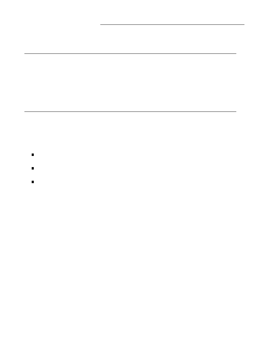
String Table
String table sections hold null-terminated character sequences, commonly called strings. The object file
uses these strings to represent symbol and section names. One references a string as an index into the
string table section. The first byte, which is index zero, is defined to hold a null character. Likewise, a
string table’s last byte is defined to hold a null character, ensuring null termination for all strings. A
string whose index is zero specifies either no name or a null name, depending on the context. An empty
string table section is permitted; its section header’s
sh_size
member would contain zero. Non-zero
indexes are invalid for an empty string table.
A section header’s
sh_name
member holds an index into the section header string table section, as desig-
nated by the
e_shstrndx
member of the ELF header. The following figures show a string table with 25
bytes and the strings associated with various indexes.
Index
+ 0
+ 1
+ 2
+ 3
+ 4
+ 5
+ 6
+ 7
+ 8
+ 9
______________________________________________________
0
\0 n a m e . \0 V a r
______________________________________________________
10
i a b l e \0 a b l e
______________________________________________________
20
\0 \0 x x \0
______________________________________________________
Figure 1-15: String Table Indexes
Index String
_ _________________
0
none
1
name.
7
Variable
11
able
16
able
24
null string
_ _________________
As the example shows, a string table index may refer to any byte in the section. A string may appear
more than once; references to substrings may exist; and a single string may be referenced multiple times.
Unreferenced strings also are allowed.
1-16
Portable Formats Specification, Version 1.1
Tool Interface Standards (TIS)
Symbol Table
An object file’s symbol table holds information needed to locate and relocate a program’s symbolic
definitions and references. A symbol table index is a subscript into this array. Index 0 both designates
the first entry in the table and serves as the undefined symbol index. The contents of the initial entry are
specified later in this section.
Name Value
___________________
STN_UNDEF 0
___________________
A symbol table entry has the following format.
Figure 1-16: Symbol Table Entry
t
y
p
e
d
e
f s
t
r
u
c
t {
E
l
f
3
2
_
W
o
r
d s
t
_
n
a
m
e
;
E
l
f
3
2
_
A
d
d
r s
t
_
v
a
l
u
e
;
E
l
f
3
2
_
W
o
r
d s
t
_
s
i
z
e
;
u
n
s
i
g
n
e
d c
h
a
r s
t
_
i
n
f
o
;
u
n
s
i
g
n
e
d c
h
a
r s
t
_
o
t
h
e
r
;
E
l
f
3
2
_
H
a
l
f s
t
_
s
h
n
d
x
;
} E
l
f
3
2
_
S
y
m
;
st_name
This member holds an index into the object file’s symbol string table, which holds the
character representations of the symbol names. If the value is non-zero, it represents a
string table index that gives the symbol name. Otherwise, the symbol table entry has no
name.
NOTE
External C symbols have the same names in C and object files’ symbol tables.
st_value
This member gives the value of the associated symbol. Depending on the context, this
may be an absolute value, an address, etc.; details appear below.
st_size
Many symbols have associated sizes. For example, a data object’s size is the number of
bytes contained in the object. This member holds 0 if the symbol has no size or an
unknown size.
st_info
This member specifies the symbol’s type and binding attributes. A list of the values and
meanings appears below. The following code shows how to manipulate the values.
#
d
e
f
i
n
e E
L
F
3
2
_
S
T
_
B
I
N
D
(
i
) (
(
i
)
>
>
4
)
#
d
e
f
i
n
e E
L
F
3
2
_
S
T
_
T
Y
P
E
(
i
) (
(
i
)
&
0
x
f
)
#
d
e
f
i
n
e E
L
F
3
2
_
S
T
_
I
N
F
O
(
b
,
t
) (
(
(
b
)
<
<
4
)
+
(
(
t
)
&
0
x
f
)
)
Tool Interface Standards (TIS)
Portable Formats Specification, Version 1.1
1-17

ELF: Executable and Linkable Format
st_other
This member currently holds 0 and has no defined meaning.
st_shndx
Every symbol table entry is ‘‘defined’’ in relation to some section; this member holds the
relevant section header table index. As Figure 1-7 and the related text describe, some
section indexes indicate special meanings.
A symbol’s binding determines the linkage visibility and behavior.
Figure 1-17: Symbol Binding,
ELF32_ST_BIND
Name Value
_
____________________
STB_LOCAL 0
STB_GLOBAL 1
STB_WEAK 2
STB_LOPROC 13
STB_HIPROC 15
_
____________________
STB_LOCAL
Local symbols are not visible outside the object file containing their definition. Local
symbols of the same name may exist in multiple files without interfering with each
other.
STB_GLOBAL
Global symbols are visible to all object files being combined. One file’s definition of a
global symbol will satisfy another file’s undefined reference to the same global symbol.
STB_WEAK
Weak symbols resemble global symbols, but their definitions have lower precedence.
STB_LOPROC
through
STB_HIPROC
Values in this inclusive range are reserved for processor-specific semantics.
Global and weak symbols differ in two major ways.
When the link editor combines several relocatable object files, it does not allow multiple definitions
of
STB_GLOBAL
symbols with the same name. On the other hand, if a defined global symbol
exists, the appearance of a weak symbol with the same name will not cause an error. The link edi-
tor honors the global definition and ignores the weak ones. Similarly, if a common symbol exists
(i.e., a symbol whose st
_
shndx field holds
SHN_COMMON
), the appearance of a weak symbol with
the same name will not cause an error. The link editor honors the common definition and ignores
the weak ones.
When the link editor searches archive libraries, it extracts archive members that contain definitions
of undefined global symbols. The member’s definition may be either a global or a weak symbol.
The link editor does not extract archive members to resolve undefined weak symbols. Unresolved
weak symbols have a zero value.
In each symbol table, all symbols with
STB_LOCAL
binding precede the weak and global symbols. As
‘‘Sections’’ above describes, a symbol table section’s
sh_info
section header member holds the symbol
table index for the first non-local symbol.
1-18
Portable Formats Specification, Version 1.1
Tool Interface Standards (TIS)

ELF: Executable and Linkable Format
A symbol’s type provides a general classification for the associated entity.
Figure 1-18: Symbol Types,
ELF32_ST_TYPE
Name Value
_ _____________________
STT_NOTYPE 0
STT_OBJECT 1
STT_FUNC 2
STT_SECTION 3
STT_FILE 4
STT_LOPROC 13
STT_HIPROC 15
_ _____________________
STT_NOTYPE
The symbol’s type is not specified.
STT_OBJECT
The symbol is associated with a data object, such as a variable, an array, etc.
STT_FUNC
The symbol is associated with a function or other executable code.
STT_SECTION
The symbol is associated with a section. Symbol table entries of this type exist pri-
marily for relocation and normally have
STB_LOCAL
binding.
STT_FILE
Conventionally, the symbol’s name gives the name of the source file associated with the
object file. A file symbol has
STB_LOCAL
binding, its section index is
SHN_ABS
, and it
precedes the other
STB_LOCAL
symbols for the file, if it is present.
STT_LOPROC
through
STT_HIPROC
Values in this inclusive range are reserved for processor-specific semantics.
Function symbols (those with type
STT_FUNC
) in shared object files have special significance. When
another object file references a function from a shared object, the link editor automatically creates a pro-
cedure linkage table entry for the referenced symbol. Shared object symbols with types other than
STT_FUNC
will not be referenced automatically through the procedure linkage table.
If a symbol’s value refers to a specific location within a section, its section index member,
st_shndx
,
holds an index into the section header table. As the section moves during relocation, the symbol’s value
changes as well, and references to the symbol continue to ‘‘point’’ to the same location in the program.
Some special section index values give other semantics.
SHN_ABS
The symbol has an absolute value that will not change because of relocation.
SHN_COMMON
The symbol labels a common block that has not yet been allocated. The symbol’s value
gives alignment constraints, similar to a section’s
sh_addralign
member. That is, the
link editor will allocate the storage for the symbol at an address that is a multiple of
st_value
. The symbol’s size tells how many bytes are required.
SHN_UNDEF
This section table index means the symbol is undefined. When the link editor combines
this object file with another that defines the indicated symbol, this file’s references to the
symbol will be linked to the actual definition.
Tool Interface Standards (TIS)
Portable Formats Specification, Version 1.1
1-19
ELF: Executable and Linkable Format
As mentioned above, the symbol table entry for index 0 (
STN_UNDEF
) is reserved; it holds the following.
Figure 1-19: Symbol Table Entry: Index 0
Name Value
Note
_
______________________________________________
st_name 0
No name
st_value 0
Zero value
st_size 0
No size
st_info 0
No type, local binding
st_other 0
st_shndx SHN_UNDEF
No section
_
______________________________________________
Symbol Values
Symbol table entries for different object file types have slightly different interpretations for the
st_value
member.
In relocatable files,
st_value
holds alignment constraints for a symbol whose section index is
SHN_COMMON
.
In relocatable files,
st_value
holds a section offset for a defined symbol. That is,
st_value
is an
offset from the beginning of the section that
st_shndx
identifies.
In executable and shared object files,
st_value
holds a virtual address. To make these files’ sym-
bols more useful for the dynamic linker, the section offset (file interpretation) gives way to a virtual
address (memory interpretation) for which the section number is irrelevant.
Although the symbol table values have similar meanings for different object files, the data allow efficient
access by the appropriate programs.
1-20
Portable Formats Specification, Version 1.1
Tool Interface Standards (TIS)

Relocation
Relocation is the process of connecting symbolic references with symbolic definitions. For example, when
a program calls a function, the associated call instruction must transfer control to the proper destination
address at execution. In other words, relocatable files must have information that describes how to
modify their section contents, thus allowing executable and shared object files to hold the right informa-
tion for a process’s program image. Relocation entries are these data.
Figure 1-20: Relocation Entries
t
y
p
e
d
e
f s
t
r
u
c
t {
E
l
f
3
2
_
A
d
d
r r
_
o
f
f
s
e
t
;
E
l
f
3
2
_
W
o
r
d r
_
i
n
f
o
;
} E
l
f
3
2
_
R
e
l
;
t
y
p
e
d
e
f s
t
r
u
c
t {
E
l
f
3
2
_
A
d
d
r r
_
o
f
f
s
e
t
;
E
l
f
3
2
_
W
o
r
d r
_
i
n
f
o
;
E
l
f
3
2
_
S
w
o
r
d r
_
a
d
d
e
n
d
;
} E
l
f
3
2
_
R
e
l
a
;
r_offset
This member gives the location at which to apply the relocation action. For a relocatable
file, the value is the byte offset from the beginning of the section to the storage unit affected
by the relocation. For an executable file or a shared object, the value is the virtual address of
the storage unit affected by the relocation.
r_info
This member gives both the symbol table index with respect to which the relocation must be
made, and the type of relocation to apply. For example, a call instruction’s relocation entry
would hold the symbol table index of the function being called. If the index is
STN_UNDEF
,
the undefined symbol index, the relocation uses 0 as the ‘‘symbol value.’’ Relocation types
are processor-specific. When the text refers to a relocation entry’s relocation type or symbol
table index, it means the result of applying
ELF32_R_TYPE
or
ELF32_R_SYM
, respectively,
to the entry’s
r_info
member.
#
d
e
f
i
n
e E
L
F
3
2
_
R
_
S
Y
M
(
i
) (
(
i
)
>
>
8
)
#
d
e
f
i
n
e E
L
F
3
2
_
R
_
T
Y
P
E
(
i
) (
(
u
n
s
i
g
n
e
d c
h
a
r
)
(
i
)
)
#
d
e
f
i
n
e E
L
F
3
2
_
R
_
I
N
F
O
(
s
,
t
) (
(
(
s
)
<
<
8
)
+
(
u
n
s
i
g
n
e
d c
h
a
r
)
(
t
)
)
r_addend
This member specifies a constant addend used to compute the value to be stored into the
relocatable field.
As shown above, only
Elf32_Rela
entries contain an explicit addend. Entries of type
Elf32_Rel
store
an implicit addend in the location to be modified. Depending on the processor architecture, one form or
the other might be necessary or more convenient. Consequently, an implementation for a particular
machine may use one form exclusively or either form depending on context.
Tool Interface Standards (TIS)
Portable Formats Specification, Version 1.1
1-21
ELF: Executable and Linkable Format
A relocation section references two other sections: a symbol table and a section to modify. The section
header’s
sh_info
and
sh_link
members, described in ‘‘Sections’’ above, specify these relationships.
Relocation entries for different object files have slightly different interpretations for the
r_offset
member.
In relocatable files,
r_offset
holds a section offset. That is, the relocation section itself describes
how to modify another section in the file; relocation offsets designate a storage unit within the
second section.
In executable and shared object files,
r_offset
holds a virtual address. To make these files’ relo-
cation entries more useful for the dynamic linker, the section offset (file interpretation) gives way to
a virtual address (memory interpretation).
Although the interpretation of
r_offset
changes for different object files to allow efficient access by the
relevant programs, the relocation types’ meanings stay the same.
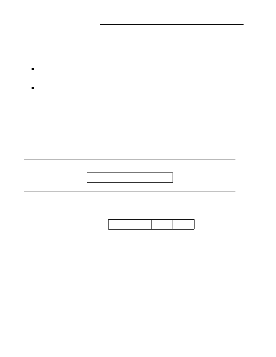
Relocation Types
Relocation entries describe how to alter the following instruction and data fields (bit numbers appear in
the lower box corners).
Figure 1-21: Relocatable Fields
word32
31 0
word32
This specifies a 32-bit field occupying 4 bytes with arbitrary byte alignment. These values use
the same byte order as other word values in the 32-bit Intel Architecture.
01
3
31
02
2
03
1
04
0
0
0x01020304
Calculations below assume the actions are transforming a relocatable file into either an executable or a
shared object file. Conceptually, the link editor merges one or more relocatable files to form the output.
It first decides how to combine and locate the input files, then updates the symbol values, and finally per-
forms the relocation. Relocations applied to executable or shared object files are similar and accomplish
the same result. Descriptions below use the following notation.
A
This means the addend used to compute the value of the relocatable field.
B
This means the base address at which a shared object has been loaded into memory during
execution. Generally, a shared object file is built with a 0 base virtual address, but the execu-
tion address will be different.
1-22
Portable Formats Specification, Version 1.1
Tool Interface Standards (TIS)

ELF: Executable and Linkable Format
G
This means the offset into the global offset table at which the address of the relocation entry’s
symbol will reside during execution. See ‘‘Global Offset Table’’ in Part 2 for more informa-
tion.
GOT
This means the address of the global offset table. See ‘‘Global Offset Table’’ in Part 2 for more
information.
L
This means the place (section offset or address) of the procedure linkage table entry for a sym-
bol. A procedure linkage table entry redirects a function call to the proper destination. The
link editor builds the initial procedure linkage table, and the dynamic linker modifies the
entries during execution. See ‘‘Procedure Linkage Table’’ in Part 2 for more information.
P
This means the place (section offset or address) of the storage unit being relocated (computed
using
r_offset
).
S
This means the value of the symbol whose index resides in the relocation entry.
A relocation entry’s
r_offset
value designates the offset or virtual address of the first byte of the
affected storage unit. The relocation type specifies which bits to change and how to calculate their values.
The SYSTEM V architecture uses only
Elf32_Rel
relocation entries, the field to be relocated holds the
addend. In all cases, the addend and the computed result use the same byte order.
Figure 1-22: Relocation Types
Name Value
Field
Calculation
_ __________________________________________________
R_386_NONE 0
none none
R_386_32 1
word32
S + A
R_386_PC32 2
word32
S + A - P
R_386_GOT32 3
word32
G + A - P
R_386_PLT32 4
word32
L + A - P
R_386_COPY 5
none none
R_386_GLOB_DAT 6
word32
S
R_386_JMP_SLOT 7
word32
S
R_386_RELATIVE 8
word32
B + A
R_386_GOTOFF 9
word32
S + A - GOT
R_386_GOTPC 10
word32
GOT + A - P
_ __________________________________________________
Some relocation types have semantics beyond simple calculation.
R_386_GOT32
This relocation type computes the distance from the base of the global offset
table to the symbol’s global offset table entry. It additionally instructs the link
editor to build a global offset table.
R_386_PLT32
This relocation type computes the address of the symbol’s procedure linkage
table entry and additionally instructs the link editor to build a procedure linkage
table.
R_386_COPY
The link editor creates this relocation type for dynamic linking. Its offset
member refers to a location in a writable segment. The symbol table index
specifies a symbol that should exist both in the current object file and in a shared
object. During execution, the dynamic linker copies data associated with the
shared object’s symbol to the location specified by the offset.
Tool Interface Standards (TIS)
Portable Formats Specification, Version 1.1
1-23

ELF: Executable and Linkable Format
R_386_GLOB_DAT
This relocation type is used to set a global offset table entry to the address of the
specified symbol. The special relocation type allows one to determine the
correspondence between symbols and global offset table entries.
R_3862_JMP_SLOT
The link editor creates this relocation type for dynamic linking. Its offset
member gives the location of a procedure linkage table entry. The dynamic
linker modifies the procedure linkage table entry to transfer control to the desig-
nated symbol’s address [see ‘‘Procedure Linkage Table’’ in Part 2].
R_386_RELATIVE
The link editor creates this relocation type for dynamic linking. Its offset
member gives a location within a shared object that contains a value represent-
ing a relative address. The dynamic linker computes the corresponding virtual
address by adding the virtual address at which the shared object was loaded to
the relative address. Relocation entries for this type must specify 0 for the sym-
bol table index.
R_386_GOTOFF
This relocation type computes the difference between a symbol’s value and the
address of the global offset table. It additionally instructs the link editor to build
the global offset table.
R_386_GOTPC
This relocation type resembles
R_386_PC32
, except it uses the address of the
global offset table in its calculation. The symbol referenced in this relocation
normally is
_GLOBAL_OFFSET_TABLE_
, which additionally instructs the link
editor to build the global offset table.
1-24
Portable Formats Specification, Version 1.1
Tool Interface Standards (TIS)

2
PROGRAM LOADING AND DYNAMIC LINKING
Introduction
2-1
Program Header
2-2
Base Address
2-4
Note Section
2-4
Program Loading
2-7
Dynamic Linking
2-10
Program Interpreter
2-10
Dynamic Linker
2-10
Dynamic Section
2-11
Shared Object Dependencies
2-15
Global Offset Table
2-16
Procedure Linkage Table
2-17
Hash Table
2-19
Initialization and Termination Functions
2-20
Tool Interface Standards (TIS)
Portable Formats Specification, Version 1.1
i
Introduction
Part 2 describes the object file information and system actions that create running programs. Some infor-
mation here applies to all systems; other information is processor-specific.
Executable and shared object files statically represent programs. To execute such programs, the system
uses the files to create dynamic program representations, or process images. A process image has seg-
ments that hold its text, data, stack, and so on. The major sections in this part discuss the following.
Program header. This section complements Part 1, describing object file structures that relate directly
to program execution. The primary data structure, a program header table, locates segment images
within the file and contains other information necessary to create the memory image for the pro-
gram.
Program loading. Given an object file, the system must load it into memory for the program to run.
Dynamic linking. After the system loads the program, it must complete the process image by resolv-
ing symbolic references among the object files that compose the process.
NOTE
There are naming conventions for ELF constants that have specified processor ranges. Names such as
DT
_
, PT
_
, for processor-specific extensions, incorporate the name of the processor:
DT
_
M32
_
SPECIAL, for example. Pre
–
existing processor extensions not using this convention will be
supported.
Pre-existing Extensions
_ ____________________
D
T
_
J
M
P
_
R
E
L
Tool Interface Standards (TIS)
Portable Formats Specification, Version 1.1
2-1
Program Header
An executable or shared object file’s program header table is an array of structures, each describing a seg-
ment or other information the system needs to prepare the program for execution. An object file segment
contains one or more sections, as ‘‘Segment Contents’’ describes below. Program headers are meaningful
only for executable and shared object files. A file specifies its own program header size with the ELF
header’s
e
_
p
h
e
n
t
s
i
z
e
and
e
_
p
h
n
u
m
members [see ‘‘ELF Header’’ in Part 1].
Figure 2-1: Program Header
t
y
p
e
d
e
f s
t
r
u
c
t {
E
l
f
3
2
_
W
o
r
d p
_
t
y
p
e
;
E
l
f
3
2
_
O
f
f p
_
o
f
f
s
e
t
;
E
l
f
3
2
_
A
d
d
r p
_
v
a
d
d
r
;
E
l
f
3
2
_
A
d
d
r p
_
p
a
d
d
r
;
E
l
f
3
2
_
W
o
r
d p
_
f
i
l
e
s
z
;
E
l
f
3
2
_
W
o
r
d p
_
m
e
m
s
z
;
E
l
f
3
2
_
W
o
r
d p
_
f
l
a
g
s
;
E
l
f
3
2
_
W
o
r
d p
_
a
l
i
g
n
;
} E
l
f
3
2
_
P
h
d
r
;
p_type
This member tells what kind of segment this array element describes or how to interpret
the array element’s information. Type values and their meanings appear below.
p_offset
This member gives the offset from the beginning of the file at which the first byte of the
segment resides.
p_vaddr
This member gives the virtual address at which the first byte of the segment resides in
memory.
p_paddr
On systems for which physical addressing is relevant, this member is reserved for the
segment’s physical address. Because System V ignores physical addressing for applica-
tion programs, this member has unspecified contents for executable files and shared
objects.
p_filesz
This member gives the number of bytes in the file image of the segment; it may be zero.
p_memsz
This member gives the number of bytes in the memory image of the segment; it may be
zero.
p_flags
This member gives flags relevant to the segment. Defined flag values appear below.
p_align
As ‘‘Program Loading’’ later in this part describes, loadable process segments must have
congruent values for
p_vaddr
and
p_offset
, modulo the page size. This member
gives the value to which the segments are aligned in memory and in the file. Values 0
and 1 mean no alignment is required. Otherwise,
p_align
should be a positive, integral
power of 2, and
p_vaddr
should equal
p_offset
, modulo
p_align
.
Some entries describe process segments; others give supplementary information and do not contribute to
the process image. Segment entries may appear in any order, except as explicitly noted below. Defined
type values follow; other values are reserved for future use.
2-2
Portable Formats Specification, Version 1.1
Tool Interface Standards (TIS)

ELF: Executable and Linkable Format
Figure 2-2: Segment Types,
p_type
Name Value
___________________________
PT_NULL 0
PT_LOAD 1
PT_DYNAMIC 2
PT_INTERP 3
PT_NOTE 4
PT_SHLIB 5
PT_PHDR 6
PT_LOPROC 0x70000000
PT_HIPROC 0x7fffffff
___________________________
PT_NULL
The array element is unused; other members’ values are undefined. This type lets the
program header table have ignored entries.
PT_LOAD
The array element specifies a loadable segment, described by
p_filesz
and
p_memsz
.
The bytes from the file are mapped to the beginning of the memory segment. If the
segment’s memory size (
p_memsz
) is larger than the file size (
p_filesz
), the ‘‘extra’’
bytes are defined to hold the value 0 and to follow the segment’s initialized area. The file
size may not be larger than the memory size. Loadable segment entries in the program
header table appear in ascending order, sorted on the
p_vaddr
member.
PT_DYNAMIC
The array element specifies dynamic linking information. See ‘‘Dynamic Section’’ below
for more information.
PT_INTERP
The array element specifies the location and size of a null-terminated path name to
invoke as an interpreter. This segment type is meaningful only for executable files
(though it may occur for shared objects); it may not occur more than once in a file. If it is
present, it must precede any loadable segment entry. See ‘‘Program Interpreter’’ below
for further information.
PT_NOTE
The array element specifies the location and size of auxiliary information. See ‘‘Note Sec-
tion’’ below for details.
PT_SHLIB
This segment type is reserved but has unspecified semantics. Programs that contain an
array element of this type do not conform to the ABI.
PT_PHDR
The array element, if present, specifies the location and size of the program header table
itself, both in the file and in the memory image of the program. This segment type may
not occur more than once in a file. Moreover, it may occur only if the program header
table is part of the memory image of the program. If it is present, it must precede any
loadable segment entry. See ‘‘Program Interpreter’’ below for further information.
PT_LOPROC
through
PT_HIPROC
Values in this inclusive range are reserved for processor-specific semantics.
Tool Interface Standards (TIS)
Portable Formats Specification, Version 1.1
2-3

ELF: Executable and Linkable Format
NOTE
Unless specifically required elsewhere, all program header segment types are optional. That is, a file’s
program header table may contain only those elements relevant to its contents.
Base Address
Executable and shared object files have a base address, which is the lowest virtual address associated with
the memory image of the program’s object file. One use of the base address is to relocate the memory
image of the program during dynamic linking.
An executable or shared object file’s base address is calculated during execution from three values: the
memory load address, the maximum page size, and the lowest virtual address of a program’s loadable
segment. As ‘‘Program Loading’’
in this chapter describes, the virtual addresses in the program headers might not represent the actual vir-
tual addresses of the program’s memory image. To compute the base address, one determines the
memory address associated with the lowest
p_vaddr
value for a
PT_LOAD
segment. One then obtains
the base address by truncating the memory address to the nearest multiple of the maximum page size.
Depending on the kind of file being loaded into memory, the memory address might or might not match
the
p_vaddr
values.
As ‘‘Sections’’ in Part 1 describes, the
.bss
section has the type
SHT_NOBITS
. Although it occupies no
space in the file, it contributes to the segment’s memory image. Normally, these uninitialized data reside
at the end of the segment, thereby making
p_memsz
larger than
p_filesz
in the associated program
header element.
Note Section
Sometimes a vendor or system builder needs to mark an object file with special information that other
programs will check for conformance, compatibility, etc. Sections of type
SHT_NOTE
and program
header elements of type
PT_NOTE
can be used for this purpose. The note information in sections and
program header elements holds any number of entries, each of which is an array of 4-byte words in the
format of the target processor. Labels appear below to help explain note information organization, but
they are not part of the specification.
Figure 2-3: Note Information
_ _________
namesz
_ _________
descsz
_ _________
type
_ _________
name
. . .
_ _________
desc
. . .
_ _________
2-4
Portable Formats Specification, Version 1.1
Tool Interface Standards (TIS)

ELF: Executable and Linkable Format
namesz
and
name
The first
namesz
bytes in
name
contain a null-terminated character representation of the
entry’s owner or originator. There is no formal mechanism for avoiding name conflicts. By
convention, vendors use their own name, such as ‘‘XYZ Computer Company,’’ as the
identifier. If no name is present,
namesz
contains 0. Padding is present, if necessary, to
ensure 4-byte alignment for the descriptor. Such padding is not included in
namesz
.
descsz
and
desc
The first
descsz
bytes in
desc
hold the note descriptor. The ABI places no constraints on a
descriptor’s contents. If no descriptor is present,
descsz
contains 0. Padding is present, if
necessary, to ensure 4-byte alignment for the next note entry. Such padding is not included
in
descsz
.
type
This word gives the interpretation of the descriptor. Each originator controls its own types;
multiple interpretations of a single type value may exist. Thus, a program must recognize
both the name and the type to ‘‘understand’’ a descriptor. Types currently must be non-
negative. The ABI does not define what descriptors mean.
To illustrate, the following note segment holds two entries.
Figure 2-4: Example Note Segment
+0 +1 +2 +3
_ _____________________
namesz 7
_ _____________________
descsz 0
No descriptor
_ _____________________
type 1
_ _____________________
name
X Y Z
_ _____________________
C
o
\0
pad
_ _____________________
_ _____________________
namesz 7
_ _____________________
descsz 8
_ _____________________
type 3
_ _____________________
name
X Y Z
_ _____________________
C
o
\0
pad
_ _____________________
desc
word 0
_ _____________________
word 1
_ _____________________
NOTE
The system reserves note information with no name (
namesz=
=0
) and with a zero-length name
(
name[0]=
=’\0’
) but currently defines no types. All other names must have at least one non-null
character.
Tool Interface Standards (TIS)
Portable Formats Specification, Version 1.1
2-5

ELF: Executable and Linkable Format
NOTE
Note information is optional. The presence of note information does not affect a program’s ABI confor-
mance, provided the information does not affect the program’s execution behavior. Otherwise, the pro-
gram does not conform to the ABI and has undefined behavior.
2-6
Portable Formats Specification, Version 1.1
Tool Interface Standards (TIS)

Program Loading
As the system creates or augments a process image, it logically copies a file’s segment to a virtual
memory segment. When—and if—the system physically reads the file depends on the program’s execu-
tion behavior, system load, etc. A process does not require a physical page unless it references the logical
page during execution, and processes commonly leave many pages unreferenced. Therefore delaying
physical reads frequently obviates them, improving system performance. To obtain this efficiency in
practice, executable and shared object files must have segment images whose file offsets and virtual
addresses are congruent, modulo the page size.
Virtual addresses and file offsets for the SYSTEM V architecture segments are congruent modulo 4 KB
(
0x1000
) or larger powers of 2. Because 4 KB is the maximum page size, the files will be suitable for pag-
ing regardless of physical page size.
Figure 2-5: Executable File
File Offset
File
Virtual Address
_ ___________________
0
ELF header
_ ___________________
Program header table
_ ___________________
Other information
_ ___________________
0x100
Text segment
0x8048100
. . .
0x2be00
bytes
0x8073eff
_ ___________________
0x2bf00
Data segment
0x8074f00
. . .
0x4e00
bytes
0x8079cff
_ ___________________
0x30d00
Other information
. . .
_ ___________________
Figure 2-6: Program Header Segments
Member Text
Data
_
_____________________________________________
p_type PT_LOAD
PT_LOAD
p_offset 0x100
0x2bf00
p_vaddr 0x8048100
0x8074f00
p_paddr
unspecified unspecified
p_filesz 0x2be00
0x4e00
p_memsz 0x2be00
0x5e24
p_flags PF_R
+
PF_X PF_R
+
PF_W
+
PF_X
p_align 0x1000
0x1000
_
_____________________________________________
Although the example’s file offsets and virtual addresses are congruent modulo 4 KB for both text and
data, up to four file pages hold impure text or data (depending on page size and file system block size).
The first text page contains the ELF header, the program header table, and other information.
Tool Interface Standards (TIS)
Portable Formats Specification, Version 1.1
2-7

ELF: Executable and Linkable Format
The last text page holds a copy of the beginning of data.
The first data page has a copy of the end of text.
The last data page may contain file information not relevant to the running process.
Logically, the system enforces the memory permissions as if each segment were complete and separate;
segments’ addresses are adjusted to ensure each logical page in the address space has a single set of per-
missions. In the example above, the region of the file holding the end of text and the beginning of data
will be mapped twice: at one virtual address for text and at a different virtual address for data.
The end of the data segment requires special handling for uninitialized data, which the system defines to
begin with zero values. Thus if a file’s last data page includes information not in the logical memory
page, the extraneous data must be set to zero, not the unknown contents of the executable file. ‘‘Impuri-
ties’’ in the other three pages are not logically part of the process image; whether the system expunges
them is unspecified. The memory image for this program follows, assuming 4 KB (
0x1000
) pages.
Figure 2-7: Process Image Segments
Virtual Address
Contents
Segment
_ ___________________
0x8048000
Header padding
0x100
bytes
_ ___________________
0x8048100
Text
Text segment
. . .
0x2be00
bytes
_ ___________________
0x8073f00
Data padding
0x100
bytes
_ ___________________
_ ___________________
0x8074000
Text padding
0xf00
bytes
_ ___________________
0x8074f00
Data
Data segment
. . .
0x4e00
bytes
_ ___________________
0x8079d00
Uninitialized data
0x1024
zero bytes
_ ___________________
0x807ad24
Page padding
0x2dc
zero bytes
_ ___________________
One aspect of segment loading differs between executable files and shared objects. Executable file seg-
ments typically contain absolute code. To let the process execute correctly, the segments must reside at
the virtual addresses used to build the executable file. Thus the system uses the
p_vaddr
values
unchanged as virtual addresses.
2-8
Portable Formats Specification, Version 1.1
Tool Interface Standards (TIS)

ELF: Executable and Linkable Format
On the other hand, shared object segments typically contain position-independent code. This lets a
segment’s virtual address change from one process to another, without invalidating execution behavior.
Though the system chooses virtual addresses for individual processes, it maintains the segments’ relative
positions. Because position-independent code uses relative addressing between segments, the difference
between virtual addresses in memory must match the difference between virtual addresses in the file.
The following table shows possible shared object virtual address assignments for several processes, illus-
trating constant relative positioning. The table also illustrates the base address computations.
Figure 2-8: Example Shared Object Segment Addresses
Sourc Text
Data
Base
Address
_
_____________________________________________________
File
0x200 0x2a400
0x0
Process 1
0x80000200 0x8002a400 0x80000000
Process 2
0x80081200 0x800ab400 0x80081000
Process 3
0x900c0200 0x900ea400 0x900c0000
Process 4
0x900c6200 0x900f0400 0x900c6000
_
_____________________________________________________
Tool Interface Standards (TIS)
Portable Formats Specification, Version 1.1
2-9
Dynamic Linking
Program Interpreter
An executable file may have one
PT_INTERP
program header element. During
exec
(BA
_
OS), the sys-
tem retrieves a path name from the
PT_INTERP
segment and creates the initial process image from the
interpreter file’s segments. That is, instead of using the original executable file’s segment images, the sys-
tem composes a memory image for the interpreter. It then is the interpreter’s responsibility to receive
control from the system and provide an environment for the application program.
The interpreter receives control in one of two ways. First, it may receive a file descriptor to read the exe-
cutable file, positioned at the beginning. It can use this file descriptor to read and/or map the executable
file’s segments into memory. Second, depending on the executable file format, the system may load the
executable file into memory instead of giving the interpreter an open file descriptor. With the possible
exception of the file descriptor, the interpreter’s initial process state matches what the executable file
would have received. The interpreter itself may not require a second interpreter. An interpreter may be
either a shared object or an executable file.
A shared object (the normal case) is loaded as position-independent, with addresses that may vary
from one process to another; the system creates its segments in the dynamic segment area used by
mmap
(KE
_
OS) and related services. Consequently, a shared object interpreter typically will not
conflict with the original executable file’s original segment addresses.
An executable file is loaded at fixed addresses; the system creates its segments using the virtual
addresses from the program header table. Consequently, an executable file interpreter’s virtual
addresses may collide with the first executable file; the interpreter is responsible for resolving
conflicts.
Dynamic Linker
When building an executable file that uses dynamic linking, the link editor adds a program header ele-
ment of type
PT_INTERP
to an executable file, telling the system to invoke the dynamic linker as the pro-
gram interpreter.
NOTE
The locations of the system provided dynamic linkers are processor
–
specific.
Exec
(BA
_
OS) and the dynamic linker cooperate to create the process image for the program, which
entails the following actions:
Adding the executable file’s memory segments to the process image;
Adding shared object memory segments to the process image;
Performing relocations for the executable file and its shared objects;
Closing the file descriptor that was used to read the executable file, if one was given to the dynamic
linker;
Transferring control to the program, making it look as if the program had received control directly
from
exec
(BA
_
OS).
2-10
Portable Formats Specification, Version 1.1
Tool Interface Standards (TIS)
ELF: Executable and Linkable Format
The link editor also constructs various data that assist the dynamic linker for executable and shared object
files. As shown above in ‘‘Program Header,’’ these data reside in loadable segments, making them avail-
able during execution. (Once again, recall the exact segment contents are processor-specific. See the pro-
cessor supplement for complete information.)
A
.dynamic
section with type
SHT_DYNAMIC
holds various data. The structure residing at the
beginning of the section holds the addresses of other dynamic linking information.
The
.hash
section with type
SHT_HASH
holds a symbol hash table.
The
.got
and
.plt
sections with type
SHT_PROGBITS
hold two separate tables: the global offset
table and the procedure linkage table. Sections below explain how the dynamic linker uses and
changes the tables to create memory images for object files.
Because every ABI-conforming program imports the basic system services from a shared object library,
the dynamic linker participates in every ABI-conforming program execution.
As ‘‘Program Loading’’ explains in the processor supplement, shared objects may occupy virtual memory
addresses that are different from the addresses recorded in the file’s program header table. The dynamic
linker relocates the memory image, updating absolute addresses before the application gains control.
Although the absolute address values would be correct if the library were loaded at the addresses
specified in the program header table, this normally is not the case.
If the process environment [see
exec
(BA
_
OS)] contains a variable named
LD_BIND_NOW
with a non-null
value, the dynamic linker processes all relocation before transferring control to the program. For exam-
ple, all the following environment entries would specify this behavior.
LD_BIND_NOW=1
LD_BIND_NOW=on
LD_BIND_NOW=off
Otherwise,
LD_BIND_NOW
either does not occur in the environment or has a null value. The dynamic
linker is permitted to evaluate procedure linkage table entries lazily, thus avoiding symbol resolution and
relocation overhead for functions that are not called. See ‘‘Procedure Linkage Table’’ in this part for more
information.
Dynamic Section
If an object file participates in dynamic linking, its program header table will have an element of type
PT_DYNAMIC
. This ‘‘segment’’ contains the
.dynamic
section. A special symbol,
_DYNAMIC
, labels the
section, which contains an array of the following structures.
Tool Interface Standards (TIS)
Portable Formats Specification, Version 1.1
2-11

ELF: Executable and Linkable Format
Figure 2-9: Dynamic Structure
t
y
p
e
d
e
f s
t
r
u
c
t {
E
l
f
3
2
_
S
w
o
r
d d
_
t
a
g
;
u
n
i
o
n {
E
l
f
3
2
_
W
o
r
d d
_
v
a
l
;
E
l
f
3
2
_
A
d
d
r d
_
p
t
r
;
} d
_
u
n
;
} E
l
f
3
2
_
D
y
n
;
e
x
t
e
r
n E
l
f
3
2
_
D
y
n
_
D
Y
N
A
M
I
C
[
]
;
For each object with this type,
d_tag
controls the interpretation of
d_un
.
d_val
These
Elf32_Word
objects represent integer values with various interpretations.
d_ptr
These
Elf32_Addr
objects represent program virtual addresses. As mentioned previously,
a file’s virtual addresses might not match the memory virtual addresses during execution.
When interpreting addresses contained in the dynamic structure, the dynamic linker com-
putes actual addresses, based on the original file value and the memory base address. For
consistency, files do not contain relocation entries to ‘‘correct’’ addresses in the dynamic
structure.
The following table summarizes the tag requirements for executable and shared object files. If a tag is
marked ‘‘mandatory,’’ then the dynamic linking array for an ABI-conforming file must have an entry of
that type. Likewise, ‘‘optional’’ means an entry for the tag may appear but is not required.
Figure 2-10: Dynamic Array Tags,
d_tag
Name Value
d_un
Executable Shared
Object
_
______________________________________________________________________
DT_NULL 0
ignored mandatory
mandatory
DT_NEEDED 1
d_val
optional optional
DT_PLTRELSZ 2
d_val
optional optional
DT_PLTGOT 3
d_ptr
optional optional
DT_HASH 4
d_ptr
mandatory mandatory
DT_STRTAB 5
d_ptr
mandatory mandatory
DT_SYMTAB 6
d_ptr
mandatory mandatory
DT_RELA 7
d_ptr
mandatory optional
DT_RELASZ 8
d_val
mandatory optional
DT_RELAENT 9
d_val
mandatory optional
DT_STRSZ 10
d_val
mandatory mandatory
DT_SYMENT 11
d_val
mandatory mandatory
DT_INIT 12
d_ptr
optional optional
DT_FINI 13
d_ptr
optional optional
DT_SONAME 14
d_val
ignored optional
DT_RPATH 15
d_val
optional ignored
DT_SYMBOLIC 16
ignored ignored optional
2-12
Portable Formats Specification, Version 1.1
Tool Interface Standards (TIS)

ELF: Executable and Linkable Format
Figure 2-10: Dynamic Array Tags,
d_tag
(continued )
Name Value
d_un
Executable Shared
Object
_
______________________________________________________________________
DT_REL 17
d_ptr
mandatory optional
DT_RELSZ 18
d_val
mandatory optional
DT_RELENT 19
d_val
mandatory optional
DT_PLTREL 20
d_val
optional optional
DT_DEBUG 21
d_ptr
optional ignored
DT_TEXTREL 22
ignored optional optional
DT_JMPREL 23
d_ptr
optional optional
DT_LOPROC 0x70000000
unspecified unspecified unspecified
DT_HIPROC 0x7fffffff
unspecified unspecified unspecified
_
______________________________________________________________________
DT_NULL
An entry with a
DT_NULL
tag marks the end of the
_DYNAMIC
array.
DT_NEEDED
This element holds the string table offset of a null-terminated string, giving the name of
a needed library. The offset is an index into the table recorded in the
DT_STRTAB
entry. See ‘‘Shared Object Dependencies’’ for more information about these names.
The dynamic array may contain multiple entries with this type. These entries’ relative
order is significant, though their relation to entries of other types is not.
DT_PLTRELSZ
This element holds the total size, in bytes, of the relocation entries associated with the
procedure linkage table. If an entry of type
DT_JMPREL
is present, a
DT_PLTRELSZ
must accompany it.
DT_PLTGOT
This element holds an address associated with the procedure linkage table and/or the
global offset table. See this section in the processor supplement for details.
DT_HASH
This element holds the address of the symbol hash table, described in ‘‘Hash Table.’’
This hash table refers to the symbol table referenced by the
DT_SYMTAB
element.
DT_STRTAB
This element holds the address of the string table, described in Part 1. Symbol names,
library names, and other strings reside in this table.
DT_SYMTAB
This element holds the address of the symbol table, described in Part 1, with
Elf32_Sym
entries for the 32-bit class of files.
DT_RELA
This element holds the address of a relocation table, described in Part 1. Entries in the
table have explicit addends, such as
Elf32_Rela
for the 32-bit file class. An object file
may have multiple relocation sections. When building the relocation table for an exe-
cutable or shared object file, the link editor catenates those sections to form a single
table. Although the sections remain independent in the object file, the dynamic linker
sees a single table. When the dynamic linker creates the process image for an execut-
able file or adds a shared object to the process image, it reads the relocation table and
performs the associated actions. If this element is present, the dynamic structure must
also have
DT_RELASZ
and
DT_RELAENT
elements. When relocation is ‘‘mandatory’’
for a file, either
DT_RELA
or
DT_REL
may occur (both are permitted but not required).
DT_RELASZ
This element holds the total size, in bytes, of the
DT_RELA
relocation table.
Tool Interface Standards (TIS)
Portable Formats Specification, Version 1.1
2-13

ELF: Executable and Linkable Format
DT_RELAENT
This element holds the size, in bytes, of the
DT_RELA
relocation entry.
DT_STRSZ
This element holds the size, in bytes, of the string table.
DT_SYMENT
This element holds the size, in bytes, of a symbol table entry.
DT_INIT
This element holds the address of the initialization function, discussed in ‘‘Initialization
and Termination Functions’’ below.
DT_FINI
This element holds the address of the termination function, discussed in ‘‘Initialization
and Termination Functions’’ below.
DT_SONAME
This element holds the string table offset of a null-terminated string, giving the name of
the shared object. The offset is an index into the table recorded in the
DT_STRTAB
entry. See ‘‘Shared Object Dependencies’’ below for more information about these
names.
DT_RPATH
This element holds the string table offset of a null-terminated search library search path
string, discussed in ‘‘Shared Object Dependencies.’’ The offset is an index into the table
recorded in the
DT_STRTAB
entry.
DT_SYMBOLIC
This element’s presence in a shared object library alters the dynamic linker’s symbol
resolution algorithm for references within the library. Instead of starting a symbol
search with the executable file, the dynamic linker starts from the shared object itself. If
the shared object fails to supply the referenced symbol, the dynamic linker then
searches the executable file and other shared objects as usual.
DT_REL
This element is similar to
DT_RELA
, except its table has implicit addends, such as
Elf32_Rel
for the 32-bit file class. If this element is present, the dynamic structure
must also have
DT_RELSZ
and
DT_RELENT
elements.
DT_RELSZ
This element holds the total size, in bytes, of the
DT_REL
relocation table.
DT_RELENT
This element holds the size, in bytes, of the
DT_REL
relocation entry.
DT_PLTREL
This member specifies the type of relocation entry to which the procedure linkage table
refers. The
d_val
member holds
DT_REL
or
DT_RELA
, as appropriate. All relocations
in a procedure linkage table must use the same relocation.
DT_DEBUG
This member is used for debugging. Its contents are not specified for the ABI; pro-
grams that access this entry are not ABI-conforming.
DT_TEXTREL
This member’s absence signifies that no relocation entry should cause a modification to
a non-writable segment, as specified by the segment permissions in the program header
table. If this member is present, one or more relocation entries might request
modifications to a non-writable segment, and the dynamic linker can prepare accord-
ingly.
DT_JMPREL
If present, this entries’s
d_ptr
member holds the address of relocation entries associ-
ated solely with the procedure linkage table. Separating these relocation entries lets the
dynamic linker ignore them during process initialization, if lazy binding is enabled. If
this entry is present, the related entries of types
DT_PLTRELSZ
and
DT_PLTREL
must
also be present.
DT_LOPROC
through
DT_HIPROC
Values in this inclusive range are reserved for processor-specific semantics.
2-14
Portable Formats Specification, Version 1.1
Tool Interface Standards (TIS)
ELF: Executable and Linkable Format
Except for the
DT_NULL
element at the end of the array, and the relative order of
DT_NEEDED
elements,
entries may appear in any order. Tag values not appearing in the table are reserved.
Shared Object Dependencies
When the link editor processes an archive library, it extracts library members and copies them into the
output object file. These statically linked services are available during execution without involving the
dynamic linker. Shared objects also provide services, and the dynamic linker must attach the proper
shared object files to the process image for execution. Thus executable and shared object files describe
their specific dependencies.
When the dynamic linker creates the memory segments for an object file, the dependencies (recorded in
DT_NEEDED
entries of the dynamic structure) tell what shared objects are needed to supply the
program’s services. By repeatedly connecting referenced shared objects and their dependencies, the
dynamic linker builds a complete process image. When resolving symbolic references, the dynamic
linker examines the symbol tables with a breadth-first search. That is, it first looks at the symbol table of
the executable program itself, then at the symbol tables of the
DT_NEEDED
entries (in order), then at the
second level
DT_NEEDED
entries, and so on. Shared object files must be readable by the process; other
permissions are not required.
NOTE
Even when a shared object is referenced multiple times in the dependency list, the dynamic linker will
connect the object only once to the process.
Names in the dependency list are copies either of the
DT_SONAME
strings or the path names of the shared
objects used to build the object file. For example, if the link editor builds an executable file using one
shared object with a
DT_SONAME
entry of
lib1
and another shared object library with the path name
/usr/lib/lib2
, the executable file will contain
lib1
and
/usr/lib/lib2
in its dependency list.
If a shared object name has one or more slash (
/
) characters anywhere in the name, such as
/usr/lib/lib2
above or
directory/file
, the dynamic linker uses that string directly as the path
name. If the name has no slashes, such as
lib1
above, three facilities specify shared object path search-
ing, with the following precedence.
First, the dynamic array tag
DT_RPATH
may give a string that holds a list of directories, separated
by colons (
:
). For example, the string
/home/dir/lib:/home/dir2/lib:
tells the dynamic
linker to search first the directory
/home/dir/lib
, then
/home/dir2/lib
, and then the current
directory to find dependencies.
Second, a variable called
LD_LIBRARY_PATH
in the process environment [see
exec
(BA
_
OS)] may
hold a list of directories as above, optionally followed by a semicolon (
;
) and another directory list.
The following values would be equivalent to the previous example:
LD_LIBRARY_PATH=/home/dir/lib:/home/dir2/lib:
LD_LIBRARY_PATH=/home/dir/lib;/home/dir2/lib:
LD_LIBRARY_PATH=/home/dir/lib:/home/dir2/lib:;
All
LD_LIBRARY_PATH
directories are searched after those from
DT_RPATH
. Although some pro-
grams (such as the link editor) treat the lists before and after the semicolon differently, the dynamic
linker does not. Nevertheless, the dynamic linker accepts the semicolon notation, with the
Tool Interface Standards (TIS)
Portable Formats Specification, Version 1.1
2-15
ELF: Executable and Linkable Format
semantics described above.
Finally, if the other two groups of directories fail to locate the desired library, the dynamic linker
searches
/usr/lib
.
NOTE
For security, the dynamic linker ignores environmental search specifications (such as
LD_LIBRARY_PATH
) for set-user and set-group ID programs. It does, however, search
DT_RPATH
directories and
/usr/lib
.
Global Offset Table
Position-independent code cannot, in general, contain absolute virtual addresses. Global offset tables
hold absolute addresses in private data, thus making the addresses available without compromising the
position-independence and sharability of a program’s text. A program references its global offset table
using position-independent addressing and extracts absolute values, thus redirecting position-
independent references to absolute locations.
Initially, the global offset table holds information as required by its relocation entries [see ‘‘Relocation’’ in
Part 1]. After the system creates memory segments for a loadable object file, the dynamic linker processes
the relocation entries, some of which will be type
R_386_GLOB_DAT
referring to the global offset table.
The dynamic linker determines the associated symbol values, calculates their absolute addresses, and sets
the appropriate memory table entries to the proper values. Although the absolute addresses are
unknown when the link editor builds an object file, the dynamic linker knows the addresses of all
memory segments and can thus calculate the absolute addresses of the symbols contained therein.
If a program requires direct access to the absolute address of a symbol, that symbol will have a global
offset table entry. Because the executable file and shared objects have separate global offset tables, a
symbol’s address may appear in several tables. The dynamic linker processes all the global offset table
relocations before giving control to any code in the process image, thus ensuring the absolute addresses
are available during execution.
The table’s entry zero is reserved to hold the address of the dynamic structure, referenced with the sym-
bol
_DYNAMIC
. This allows a program, such as the dynamic linker, to find its own dynamic structure
without having yet processed its relocation entries. This is especially important for the dynamic linker,
because it must initialize itself without relying on other programs to relocate its memory image. On the
32-bit Intel Architecture, entries one and two in the global offset table also are reserved. ‘‘Procedure
Linkage Table’’ below describes them.
The system may choose different memory segment addresses for the same shared object in different pro-
grams; it may even choose different library addresses for different executions of the same program.
Nonetheless, memory segments do not change addresses once the process image is established. As long
as a process exists, its memory segments reside at fixed virtual addresses.
A global offset table’s format and interpretation are processor-specific. For the 32-bit Intel Architecture,
the symbol
_GLOBAL_OFFSET_TABLE_
may be used to access the table.
2-16
Portable Formats Specification, Version 1.1
Tool Interface Standards (TIS)
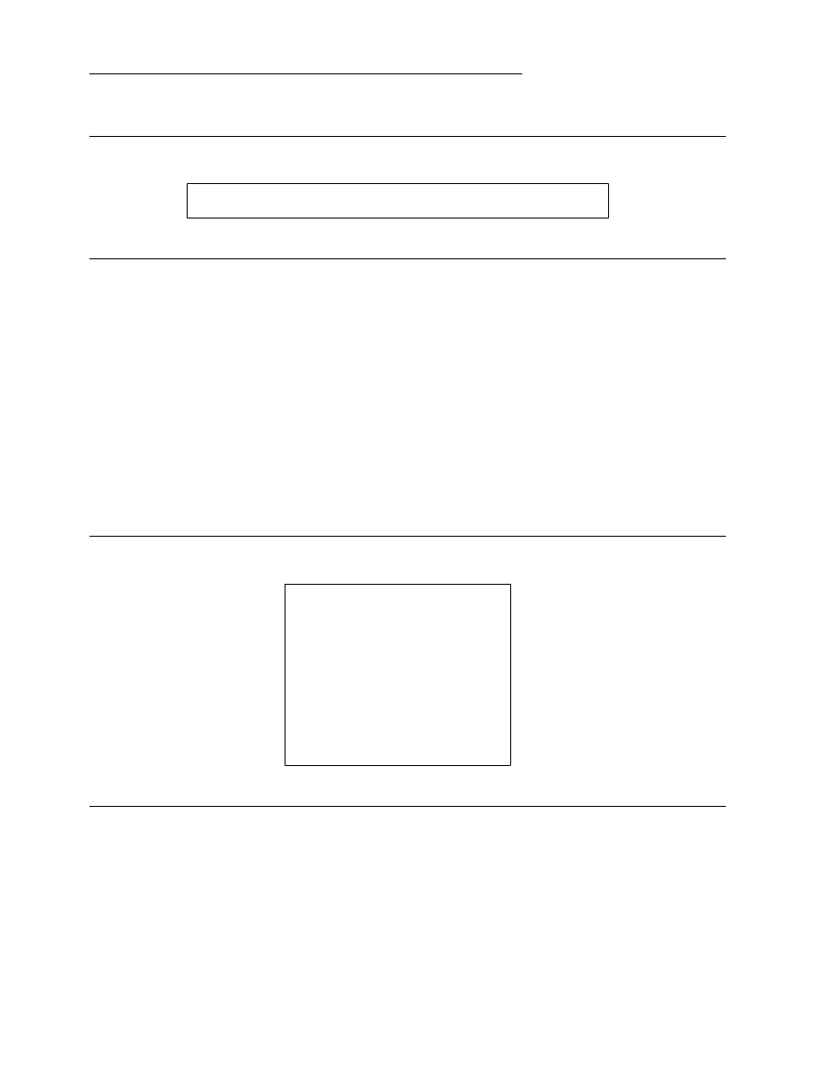
ELF: Executable and Linkable Format
Figure 2-11: Global Offset Table
extern Elf32_Addr
_GLOBAL_OFFSET_TABLE_[];
The symbol
_GLOBAL_OFFSET_TABLE_
may reside in the middle of the
.got
section, allowing both
negative and non-negative ‘‘subscripts’’ into the array of addresses.
Procedure Linkage Table
Much as the global offset table redirects position-independent address calculations to absolute locations,
the procedure linkage table redirects position-independent function calls to absolute locations. The link
editor cannot resolve execution transfers (such as function calls) from one executable or shared object to
another. Consequently, the link editor arranges to have the program transfer control to entries in the pro-
cedure linkage table. On the SYSTEM V architecture, procedure linkage tables reside in shared text, but
they use addresses in the private global offset table. The dynamic linker determines the destinations’
absolute addresses and modifies the global offset table’s memory image accordingly. The dynamic linker
thus can redirect the entries without compromising the position-independence and sharability of the
program’s text. Executable files and shared object files have separate procedure linkage tables.
Figure 2-12: Absolute Procedure Linkage Table
.PLT0:pushl
got
_
plus
_
4
jmp *
got
_
plus
_
8
nop; nop
nop; nop
.PLT1:jmp *
name1
_
in
_
GOT
pushl $
offset
@PC
.PLT2:jmp *
name2
_
in
_
GOT
push $
offset
jmp .PLT0@PC
...
Tool Interface Standards (TIS)
Portable Formats Specification, Version 1.1
2-17
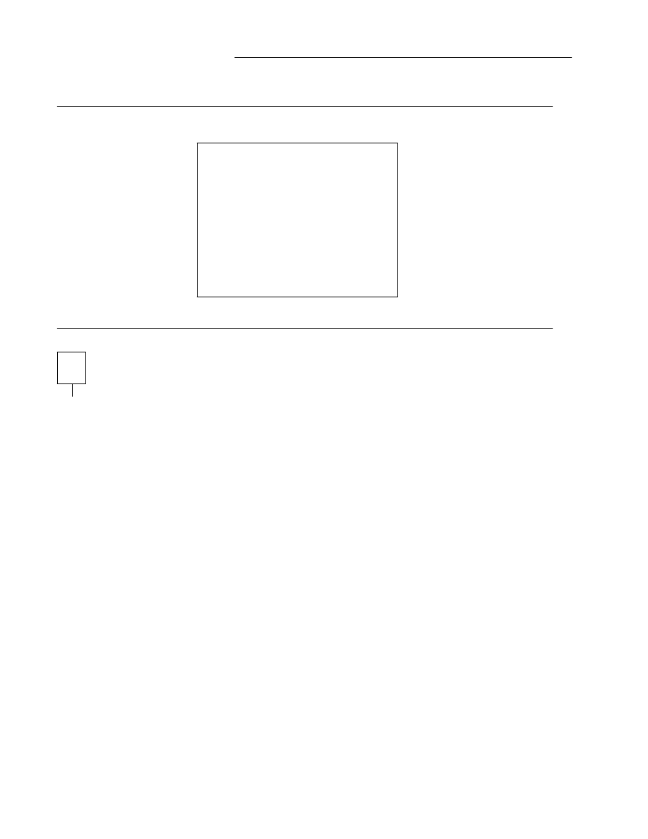
ELF: Executable and Linkable Format
Figure 2-13: Position-Independent Procedure Linkage Table
.PLT0:pushl 4(%ebx)
jmp *8(%ebx)
nop; nop
nop; nop
.PLT1:jmp *name1@GOT(%ebx)
pushl $
offset
jmp .PLT0@PC
.PLT2:jmp *name2@GOT(%ebx)
pushl $
offset
jmp .PLT0@PC
...
NOTE
As the figures show, the procedure linkage table instructions use different operand addressing modes
for absolute code and for position-independent code. Nonetheless, their interfaces to the dynamic linker
are the same.
Following the steps below, the dynamic linker and the program ‘‘cooperate’’ to resolve symbolic refer-
ences through the procedure linkage table and the global offset table.
1 . When first creating the memory image of the program, the dynamic linker sets the second and the
third entries in the global offset table to special values. Steps below explain more about these
values.
2 . If the procedure linkage table is position-independent, the address of the global offset table must
reside in
%ebx
. Each shared object file in the process image has its own procedure linkage table,
and control transfers to a procedure linkage table entry only from within the same object file. Con-
sequently, the calling function is responsible for setting the global offset table base register before
calling the procedure linkage table entry.
3 . For illustration, assume the program calls
name1
, which transfers control to the label
.PLT1
.
4 . The first instruction jumps to the address in the global offset table entry for
name1
. Initially, the
global offset table holds the address of the following
pushl
instruction, not the real address of
name1
.
5 . Consequently, the program pushes a relocation offset (offset) on the stack. The relocation offset is a
32-bit, non-negative byte offset into the relocation table. The designated relocation entry will have
type
R_386_JMP_SLOT
, and its offset will specify the global offset table entry used in the previous
jmp
instruction. The relocation entry also contains a symbol table index, thus telling the dynamic
linker what symbol is being referenced,
name1
in this case.
6 . After pushing the relocation offset, the program then jumps to
.PLT0
, the first entry in the pro-
cedure linkage table. The
pushl
instruction places the value of the second global offset table entry
(got
_
plus
_
4 or
4(%ebx)
) on the stack, thus giving the dynamic linker one word of identifying
information. The program then jumps to the address in the third global offset table entry
2-18
Portable Formats Specification, Version 1.1
Tool Interface Standards (TIS)

ELF: Executable and Linkable Format
(got
_
plus
_
8 or
8(%ebx)
), which transfers control to the dynamic linker.
7 . When the dynamic linker receives control, it unwinds the stack, looks at the designated relocation
entry, finds the symbol’s value, stores the ‘‘real’’ address for
name1
in its global offset table entry,
and transfers control to the desired destination.
8 . Subsequent executions of the procedure linkage table entry will transfer directly to
name1
, without
calling the dynamic linker a second time. That is, the
jmp
instruction at
.PLT1
will transfer to
name1
, instead of ‘‘falling through’’ to the
pushl
instruction.
The
LD_BIND_NOW
environment variable can change dynamic linking behavior. If its value is non-null,
the dynamic linker evaluates procedure linkage table entries before transferring control to the program.
That is, the dynamic linker processes relocation entries of type
R_386_JMP_SLOT
during process initiali-
zation. Otherwise, the dynamic linker evaluates procedure linkage table entries lazily, delaying symbol
resolution and relocation until the first execution of a table entry.
NOTE
Lazy binding generally improves overall application performance, because unused symbols do not incur
the dynamic linking overhead. Nevertheless, two situations make lazy binding undesirable for some
applications. First, the initial reference to a shared object function takes longer than subsequent calls,
because the dynamic linker intercepts the call to resolve the symbol. Some applications cannot tolerate
this unpredictability. Second, if an error occurs and the dynamic linker cannot resolve the symbol, the
dynamic linker will terminate the program. Under lazy binding, this might occur at arbitrary times. Once
again, some applications cannot tolerate this unpredictability. By turning off lazy binding, the dynamic
linker forces the failure to occur during process initialization, before the application receives control.
Hash Table
A hash table of
Elf32_Word
objects supports symbol table access. Labels appear below to help explain
the hash table organization, but they are not part of the specification.
Figure 2-14: Symbol Hash Table
_
_______________________
nbucket
_
_______________________
nchain
_
_______________________
bucket[0]
. . .
bucket[nbucket
-
1]
_
_______________________
chain[0]
. . .
chain[nchain
-
1]
_
_______________________
The
bucket
array contains
nbucket
entries, and the
chain
array contains
nchain
entries; indexes
start at 0. Both
bucket
and
chain
hold symbol table indexes. Chain table entries parallel the symbol
table. The number of symbol table entries should equal
nchain
; so symbol table indexes also select
chain table entries. A hashing function (shown below) accepts a symbol name and returns a value that
may be used to compute a
bucket
index. Consequently, if the hashing function returns the value x for
some name,
bucket[
x
%nbucket]
gives an index, y, into both the symbol table and the chain table. If
the symbol table entry is not the one desired,
chain[
y
]
gives the next symbol table entry with the same
hash value. One can follow the
chain
links until either the selected symbol table entry holds the desired
Tool Interface Standards (TIS)
Portable Formats Specification, Version 1.1
2-19
ELF: Executable and Linkable Format
name or the
chain
entry contains the value
STN_UNDEF
.
Figure 2-15: Hashing Function
u
n
s
i
g
n
e
d l
o
n
g
e
l
f
_
h
a
s
h
(
c
o
n
s
t u
n
s
i
g
n
e
d c
h
a
r *
n
a
m
e
)
{
u
n
s
i
g
n
e
d l
o
n
g
h = 0
, g
;
w
h
i
l
e (
*
n
a
m
e
)
{
h = (
h <
< 4
) + *
n
a
m
e
+
+
;
i
f (
g = h & 0
x
f
0
0
0
0
0
0
0
)
h ^
= g >
> 2
4
;
h &
= ~
g
;
}
r
e
t
u
r
n h
;
}
Initialization and Termination Functions
After the dynamic linker has built the process image and performed the relocations, each shared object
gets the opportunity to execute some initialization code. These initialization functions are called in no
specified order, but all shared object initializations happen before the executable file gains control.
Similarly, shared objects may have termination functions, which are executed with the
atexit
(BA
_
OS)
mechanism after the base process begins its termination sequence. Once again, the order in which the
dynamic linker calls termination functions is unspecified.
Shared objects designate their initialization and termination functions through the
DT_INIT
and
DT_FINI
entries in the dynamic structure, described in ‘‘Dynamic Section’’ above. Typically, the code
for these functions resides in the
.init
and
.fini
sections, mentioned in ‘‘Sections’’ of Part 1.
NOTE
Although the
atexit
(BA
_
OS) termination processing normally will be done, it is not guaranteed to
have executed upon process death. In particular, the process will not execute the termination process-
ing if it calls
_exit
[see
exit
(BA
_
OS)] or if the process dies because it received a signal that it nei-
ther caught nor ignored.
2-20
Portable Formats Specification, Version 1.1
Tool Interface Standards (TIS)

3
C LIBRARY
C Library
3-1
Global Data Symbols
3-2
Tool Interface Standards (TIS)
Portable Formats Specification, Version 1.1
i

C Library
The C library,
l
i
b
c
, contains all of the symbols contained in
l
i
b
s
y
s
, and, in addition, contains the rou-
tines listed in the following two tables. The first table lists routines from the ANSI C standard.
Figure 3-1:
l
i
b
c
Contents, Names without Synonyms
a
b
o
r
t f
p
u
t
c i
s
p
r
i
n
t p
u
t
c s
t
r
n
c
m
p
a
b
s f
p
u
t
s i
s
p
u
n
c
t p
u
t
c
h
a
r s
t
r
n
c
p
y
a
s
c
t
i
m
e f
r
e
a
d i
s
s
p
a
c
e p
u
t
s s
t
r
p
b
r
k
a
t
o
f f
r
e
o
p
e
n i
s
u
p
p
e
r q
s
o
r
t s
t
r
r
c
h
r
a
t
o
i f
r
e
x
p i
s
x
d
i
g
i
t r
a
i
s
e s
t
r
s
p
n
a
t
o
l f
s
c
a
n
f l
a
b
s r
a
n
d s
t
r
s
t
r
b
s
e
a
r
c
h f
s
e
e
k l
d
e
x
p r
e
w
i
n
d s
t
r
t
o
d
c
l
e
a
r
e
r
r f
s
e
t
p
o
s l
d
i
v s
c
a
n
f s
t
r
t
o
k
c
l
o
c
k f
t
e
l
l l
o
c
a
l
t
i
m
e s
e
t
b
u
f s
t
r
t
o
l
c
t
i
m
e f
w
r
i
t
e l
o
n
g
j
m
p s
e
t
j
m
p s
t
r
t
o
u
l
d
i
f
f
t
i
m
e g
e
t
c m
b
l
e
n s
e
t
v
b
u
f t
m
p
f
i
l
e
d
i
v g
e
t
c
h
a
r m
b
s
t
o
w
c
s s
p
r
i
n
t
f t
m
p
n
a
m
f
c
l
o
s
e g
e
t
e
n
v m
b
t
o
w
c s
r
a
n
d t
o
l
o
w
e
r
f
e
o
f g
e
t
s m
e
m
c
h
r s
s
c
a
n
f t
o
u
p
p
e
r
f
e
r
r
o
r g
m
t
i
m
e m
e
m
c
m
p s
t
r
c
a
t u
n
g
e
t
c
f
f
l
u
s
h i
s
a
l
n
u
m m
e
m
c
p
y s
t
r
c
h
r v
f
p
r
i
n
t
f
f
g
e
t
c i
s
a
l
p
h
a m
e
m
m
o
v
e s
t
r
c
m
p v
p
r
i
n
t
f
f
g
e
t
p
o
s i
s
c
n
t
r
l m
e
m
s
e
t s
t
r
c
p
y v
s
p
r
i
n
t
f
f
g
e
t
s i
s
d
i
g
i
t m
k
t
i
m
e s
t
r
c
s
p
n w
c
s
t
o
m
b
s
f
o
p
e
n i
s
g
r
a
p
h p
e
r
r
o
r s
t
r
l
e
n w
c
t
o
m
b
f
p
r
i
n
t
f i
s
l
o
w
e
r p
r
i
n
t
f s
t
r
n
c
a
t
Additionally,
l
i
b
c
holds the following services.
Figure 3-2:
l
i
b
c
Contents, Names with Synonyms
_ _
a
s
s
e
r
t g
e
t
d
a
t
e l
o
c
k
f
†
s
l
e
e
p t
e
l
l
†
c
f
g
e
t
i
s
p
e
e
d g
e
t
o
p
t l
s
e
a
r
c
h s
t
r
d
u
p t
e
m
p
n
a
m
c
f
g
e
t
o
s
p
e
e
d g
e
t
p
a
s
s m
e
m
c
c
p
y s
w
a
b t
f
i
n
d
c
f
s
e
t
i
s
p
e
e
d g
e
t
s
u
b
o
p
t m
k
f
i
f
o t
c
d
r
a
i
n t
o
a
s
c
i
i
c
f
s
e
t
o
s
p
e
e
d g
e
t
w m
k
t
e
m
p t
c
f
l
o
w _
t
o
l
o
w
e
r
c
t
e
r
m
i
d h
c
r
e
a
t
e m
o
n
i
t
o
r t
c
f
l
u
s
h t
s
e
a
r
c
h
c
u
s
e
r
i
d h
d
e
s
t
r
o
y n
f
t
w t
c
g
e
t
a
t
t
r _
t
o
u
p
p
e
r
d
u
p
2 h
s
e
a
r
c
h n
l
_
l
a
n
g
i
n
f
o t
c
g
e
t
p
g
r
p t
w
a
l
k
f
d
o
p
e
n i
s
a
s
c
i
i p
c
l
o
s
e t
c
g
e
t
s
i
d t
z
s
e
t
_ _
f
i
l
b
u
f i
s
a
t
t
y p
o
p
e
n t
c
s
e
n
d
b
r
e
a
k _
x
f
t
w
f
i
l
e
n
o i
s
n
a
n p
u
t
e
n
v t
c
s
e
t
a
t
t
r
_ _
f
l
s
b
u
f i
s
n
a
n
d
†
p
u
t
w t
c
s
e
t
p
g
r
p
f
m
t
m
s
g
†
l
f
i
n
d s
e
t
l
a
b
e
l t
d
e
l
e
t
e
† Function is at Level 2 in the SVID Issue 3 and therefore at Level 2 in the ABI.
Tool Interface Standards (TIS)
Portable Formats Specification, Version 1.1
3-1

ELF: Executable and Linkable Format
Besides the symbols listed in the With Synonyms table above, synonyms of the form
_
name exist for name
entries that are not listed with a leading underscore prepended to their name. Thus
l
i
b
c
contains both
g
e
t
o
p
t
and
_
g
e
t
o
p
t
, for example.
Of the routines listed above, the following are not defined elsewhere.
i
n
t _ _
f
i
l
b
u
f
(
F
I
L
E *
f
)
;
This function returns the next input character for
f
, filling its buffer as appropriate. It
returns
E
O
F
if an error occurs.
i
n
t _ _
f
l
s
b
u
f
(
i
n
t x
, F
I
L
E *
f
)
;
This function flushes the output characters for
f
as if
p
u
t
c
(
x
,
f
)
had been called and then
appends the value of
x
to the resulting output stream. It returns
E
O
F
if an error occurs and
x
otherwise.
i
n
t _
x
f
t
w
(
i
n
t
, c
h
a
r *
, i
n
t (
*
)
(
c
h
a
r *
, s
t
r
u
c
t s
t
a
t *
, i
n
t
)
, i
n
t
)
;
Calls to the
f
t
w
(BA
_
LIB) function are mapped to this function when applications are com-
piled. This function is identical to
f
t
w
(BA
_
LIB), except that
_
x
f
t
w
(
)
takes an interposed
first argument, which must have the value 2.
See this chapter’s other library sections for more SVID, ANSI C, and POSIX facilities. See ‘‘System Data
Interfaces’’ later in this chapter for more information.
Global Data Symbols
The
l
i
b
c
library requires that some global external data symbols be defined for its routines to work
properly. All the data symbols required for the
l
i
b
s
y
s
library must be provided by
l
i
b
c
, as well as the
data symbols listed in the table below.
For formal declarations of the data objects represented by these symbols, see the System V Interface
Definition, Third Edition or the ‘‘Data Definitions’’ section of Chapter 6 in the appropriate processor sup-
plement to the System V ABI.
For entries in the following table that are in name -
_
name form, both symbols in each pair represent the
same data. The underscore synonyms are provided to satisfy the ANSI C standard.
Figure 3-3:
l
i
b
c
Contents, Global External Data Symbols
g
e
t
d
a
t
e
_
e
r
r o
p
t
a
r
g
_
g
e
t
d
a
t
e
_
e
r
r o
p
t
e
r
r
_ _
i
o
b o
p
t
i
n
d
o
p
t
o
p
t
3-2
Tool Interface Standards (TIS)
Portable Formats Specification, Version 1.1

I
Index
Index
I-1
Tool Interface Standards (TIS)
Portable Formats Specification, Version 1.1
i

Index
2’s complement
1: 6
A
ABI conformance
1: 11, 2: 3, 6, 12, 14
a
b
o
r
t
3: 1
a
b
s
3: 1
absolute code
2: 9
absolute symbols
1: 8
address, virtual
2: 7
a
d
d
s
e
v
e
r
i
t
y
3: 1
alignment
executable file
2: 7
section
1: 10
ANSI C
3: 2
archive file
1: 18, 2: 15
a
s
c
t
i
m
e
3: 1
assembler
1: 1
symbol names
1: 17
_ _
a
s
s
e
r
t
3: 1
a
t
e
x
i
t
(BA
_
OS)
2: 20
a
t
o
f
3: 1
a
t
o
i
3: 1
a
t
o
l
3: 1
B
base address
1: 22, 2: 9, 12
definition
2: 4
b
s
e
a
r
c
h
3: 1
byte order
1: 6
C
C language
assembly names
1: 17
library (see library)
C library
3: 1
c
f
g
e
t
i
s
p
e
e
d
3: 1
c
f
g
e
t
o
s
p
e
e
d
3: 1
c
f
s
e
t
i
s
p
e
e
d
3: 1
c
f
s
e
t
o
s
p
e
e
d
3: 1
c
l
e
a
r
e
r
r
3: 1
c
l
o
c
k
3: 1
common symbols
1: 8
core file
1: 3
c
t
e
r
m
i
d
3: 1
c
t
i
m
e
3: 1
c
u
s
e
r
i
d
3: 1
D
data, uninitialized
2: 8
data representation
1: 2, 6
d
i
f
f
t
i
m
e
3: 1
d
i
v
3: 1
d
u
p
2
3: 1
_
D
Y
N
A
M
I
C
2: 11
see also dynamic linking
2: 11
dynamic library (see shared object file)
dynamic linker
1: 1, 2: 10
–
11
see also dynamic linking
2: 10
see also link editor
2: 10
see also shared object file
2: 10
dynamic linking
2: 10
base address
2: 4
_
D
Y
N
A
M
I
C
2: 11
environment
2: 11, 15, 19
hash function
2: 19
initialization function
2: 14, 20
lazy binding
2: 11, 19
L
D
_
B
I
N
D
_
N
O
W
2: 11, 19
L
D
_
L
I
B
R
A
R
Y
_
P
A
T
H
2: 15
relocation
2: 13, 16, 18
see also dynamic linker
2: 10
see also hash table
2: 13
see also procedure linkage table
2: 13
string table
2: 13
symbol resolution
2: 15
symbol table
1: 10, 14, 2: 13
termination function
2: 14, 20
dynamic segments
2: 9
E
ELF
1: 1
entry point (see process, entry point)
environment
2: 11, 15, 19
e
x
e
c
(BA
_
OS)
1: 1, 2: 10
–
11, 15
paging
2: 7
executable file
1: 1
segments
2: 9
e
x
i
t
2: 20
Tool Interface Standards (TIS)
Portable Formats Specification, Version 1.1
I-1

ELF: Executable and Linkable Format
F
f
c
l
o
s
e
3: 1
f
d
o
p
e
n
3: 1
f
e
o
f
3: 1
f
e
r
r
o
r
3: 1
f
f
l
u
s
h
3: 1
f
g
e
t
c
3: 1
f
g
e
t
p
o
s
3: 1
f
g
e
t
s
3: 1
_ _
f
i
l
b
u
f
3: 1
–
2
file, object (see object file)
file offset
2: 7
f
i
l
e
n
o
3: 1
_ _
f
l
s
b
u
f
3: 1
–
2
f
m
t
m
s
g
3: 1
f
o
p
e
n
3: 1
formats, object file
1: 1
FORTRAN
1: 8
f
p
r
i
n
t
f
3: 1
f
p
u
t
c
3: 1
f
p
u
t
s
3: 1
f
r
e
a
d
3: 1
f
r
e
o
p
e
n
3: 1
f
r
e
x
p
3: 1
f
s
c
a
n
f
3: 1
f
s
e
e
k
3: 1
f
s
e
t
p
o
s
3: 1
f
t
e
l
l
3: 1
f
t
w
(BA
_
LIB)
3: 2
f
w
r
i
t
e
3: 1
G
g
e
t
c
3: 1
g
e
t
c
h
a
r
3: 1
g
e
t
d
a
t
e
3: 1
_
g
e
t
d
a
t
e
_
e
r
r
3: 2
g
e
t
d
a
t
e
_
e
r
r
3: 2
g
e
t
e
n
v
3: 1
g
e
t
o
p
t
3: 1
_
g
e
t
o
p
t
3: 2
g
e
t
o
p
t
3: 2
g
e
t
p
a
s
s
3: 1
g
e
t
s
3: 1
g
e
t
s
u
b
o
p
t
3: 1
g
e
t
w
3: 1
global data symbols
3: 2
global offset table
1: 14, 23
–
24, 2: 11, 16
g
m
t
i
m
e
3: 1
H
hash function
2: 19
hash table
1: 12, 14, 2: 11, 13, 19
h
c
r
e
a
t
e
3: 1
h
d
e
s
t
r
o
y
3: 1
h
s
e
a
r
c
h
3: 1
I
interpreter, see program interpreter
2: 10
_ _
i
o
b
3: 2
i
s
a
l
n
u
m
3: 1
i
s
a
l
p
h
a
3: 1
i
s
a
s
c
i
i
3: 1
i
s
a
t
t
y
3: 1
i
s
c
n
t
r
l
3: 1
i
s
d
i
g
i
t
3: 1
i
s
g
r
a
p
h
3: 1
i
s
l
o
w
e
r
3: 1
i
s
n
a
n
3: 1
i
s
n
a
n
d
3: 1
i
s
p
r
i
n
t
3: 1
i
s
p
u
n
c
t
3: 1
i
s
s
p
a
c
e
3: 1
i
s
u
p
p
e
r
3: 1
i
s
x
d
i
g
i
t
3: 1
J
j
m
p
instruction
2: 17
–
18
L
l
a
b
s
3: 1
lazy binding
2: 11, 19
L
D
_
B
I
N
D
_
N
O
W
2: 11, 19
l
d
e
x
p
3: 1
l
d
i
v
3: 1
L
D
_
L
I
B
R
A
R
Y
_
P
A
T
H
2: 15
l
d
(SD
_
CMD) (see link editor)
l
f
i
n
d
3: 1
l
i
b
c
3: 0, 2
see also library
3: 0
l
i
b
c
contents
3: 1
–
2
I-2
Portable Formats Specification, Version 1.1
Tool Interface Standards (TIS)

ELF: Executable and Linkable Format
library
dynamic (see shared object file)
see also
l
i
b
c
3: 0
shared (see shared object file)
l
i
b
s
y
s
3: 1
–
2
link editor
1: 1, 18
–
19, 23, 2: 11, 13, 15
–
16
see also dynamic linker
2: 10
l
o
c
a
l
t
i
m
e
3: 1
l
o
c
k
f
3: 1
l
o
n
g
j
m
p
3: 1
l
s
e
a
r
c
h
3: 1
M
magic number
1: 4
–
5
m
a
i
n
1: 14
m
b
l
e
n
3: 1
m
b
s
t
o
w
c
s
3: 1
m
b
t
o
w
c
3: 1
m
e
m
c
c
p
y
3: 1
m
e
m
c
h
r
3: 1
m
e
m
c
m
p
3: 1
m
e
m
c
p
y
3: 1
m
e
m
m
o
v
e
3: 1
m
e
m
s
e
t
3: 1
m
k
f
i
f
o
3: 1
m
k
t
e
m
p
3: 1
m
k
t
i
m
e
3: 1
m
m
a
p
(KE
_
OS)
2: 10
m
o
n
i
t
o
r
3: 1
N
n
f
t
w
3: 1
n
l
_
l
a
n
g
i
n
f
o
3: 1
O
object file
1: 1
archive file
1: 18
data representation
1: 2
data types
1: 2
ELF header
1: 1, 3
extensions
1: 4
format
1: 1
hash table
2: 11, 13, 19
program header
1: 2, 2: 2
program loading
2: 2
relocation
1: 12, 21, 2: 13
section
1: 1, 8
section alignment
1: 10
section attributes
1: 12
section header
1: 2, 8
section names
1: 15
section types
1: 10
see also archive file
1: 1
see also dynamic linking
2: 10
see also executable file
1: 1
see also relocatable file
1: 1
see also shared object file
1: 1
segment
2: 1
–
2, 7
shared object file
2: 10
special sections
1: 13
string table
1: 12, 16
–
17
symbol table
1: 12, 17
type
1: 3
version
1: 4
o
p
t
a
r
g
3: 2
o
p
t
e
r
r
3: 2
o
p
t
i
n
d
3: 2
P
page size
2: 7
paging
2: 7
performance
2: 7
p
c
l
o
s
e
3: 1
performance, paging
2: 7
p
e
r
r
o
r
3: 1
p
o
p
e
n
3: 1
position-independent code
2: 9, 11
POSIX
3: 2
p
r
i
n
t
f
3: 1
procedure linkage table
1: 15, 19, 23
–
24, 2: 11,
13
–
14, 17
process
entry point
1: 4, 14, 2: 20
image
1: 1, 2: 1
–
2
virtual addressing
2: 2
processor-specific
2: 10
processor-specific information
1: 4, 6
–
8, 11
–
12,
18
–
19, 21, 2: 1, 3, 7, 11, 14, 16
–
17, 19
program header
2: 2
program interpreter
1: 14, 2: 10
program loading
2: 1, 7
Tool Interface Standards (TIS)
Portable Formats Specification, Version 1.1
I-3

ELF: Executable and Linkable Format
p
u
s
h
l
instruction
2: 17
–
18
p
u
t
c
3: 1
p
u
t
c
(BA
_
LIB)
3: 2
p
u
t
c
h
a
r
3: 1
p
u
t
e
n
v
3: 1
p
u
t
s
3: 1
p
u
t
w
3: 1
Q
q
s
o
r
t
3: 1
R
r
a
i
s
e
3: 1
r
a
n
d
3: 1
relocatable file
1: 1
relocation, see object file
1: 21
r
e
w
i
n
d
3: 1
S
s
c
a
n
f
3: 1
section, object file
2: 7
segment
dynamic
2: 10
–
11
object file
2: 1
–
2
permissions
2: 8
process
2: 1, 7, 10, 15
–
16
program header
2: 2
s
e
t
b
u
f
3: 1
s
e
t
j
m
p
3: 1
set-user ID programs
2: 16
s
e
t
v
b
u
f
3: 1
shared library (see shared object file)
shared object file
1: 1
functions
1: 19
see also dynamic linking
2: 10
see also object file
2: 10
segments
2: 9
shell scripts
1: 1
s
l
e
e
p
3: 1
s
p
r
i
n
t
f
3: 1
s
r
a
n
d
3: 1
s
s
c
a
n
f
3: 1
s
t
r
c
a
t
3: 1
s
t
r
c
h
r
3: 1
s
t
r
c
m
p
3: 1
s
t
r
c
p
y
3: 1
s
t
r
c
s
p
n
3: 1
s
t
r
d
u
p
3: 1
string table, see object file
1: 16
s
t
r
l
e
n
3: 1
s
t
r
n
c
a
t
3: 1
s
t
r
n
c
m
p
3: 1
s
t
r
n
c
p
y
3: 1
s
t
r
p
b
r
k
3: 1
s
t
r
r
c
h
r
3: 1
s
t
r
s
p
n
3: 1
s
t
r
s
t
r
3: 1
s
t
r
t
o
d
3: 1
s
t
r
t
o
k
3: 1
s
t
r
t
o
l
3: 1
s
t
r
t
o
u
l
3: 1
s
w
a
b
3: 1
symbol names, C and assembly
1: 17
symbol table, see object file
1: 17
symbols
absolute
1: 8
binding
1: 18
common
1: 8
see also hash table
1: 14
shared object file functions
1: 19
type
1: 18
undefined
1: 8
value
1: 18, 20
SYSTEM V
2: 7
T
t
c
d
r
a
i
n
3: 1
t
c
f
l
o
w
3: 1
t
c
f
l
u
s
h
3: 1
t
c
g
e
t
a
t
t
r
3: 1
t
c
g
e
t
p
g
r
p
3: 1
t
c
g
e
t
s
i
d
3: 1
t
c
s
e
n
d
b
r
e
a
k
3: 1
t
c
s
e
t
a
t
t
r
3: 1
t
c
s
e
t
p
g
r
p
3: 1
t
d
e
l
e
t
e
3: 1
t
e
l
l
3: 1
t
e
m
p
n
a
m
3: 1
t
f
i
n
d
3: 1
t
m
p
f
i
l
e
3: 1
t
m
p
n
a
m
3: 1
I-4
Portable Formats Specification, Version 1.1
Tool Interface Standards (TIS)

ELF: Executable and Linkable Format
t
o
a
s
c
i
i
3: 1
_
t
o
l
o
w
e
r
3: 1
t
o
l
o
w
e
r
3: 1
_
t
o
u
p
p
e
r
3: 1
t
o
u
p
p
e
r
3: 1
t
s
e
a
r
c
h
3: 1
t
w
a
l
k
3: 1
t
z
s
e
t
3: 1
U
undefined behavior
1: 10, 2: 6
–
7
undefined symbols
1: 8
u
n
g
e
t
c
3: 1
uninitialized data
2: 8
unspecified property
1: 2
–
3, 9, 11, 14, 2: 2
–
3, 5, 7
–
8,
14, 20
V
v
f
p
r
i
n
t
f
3: 1
virtual addressing
2: 2
v
p
r
i
n
t
f
3: 1
v
s
p
r
i
n
t
f
3: 1
W
w
c
s
t
o
m
b
s
3: 1
w
c
t
o
m
b
3: 1
X
_
x
f
t
w
3: 1
–
2
Z
zero, uninitialized data
2: 8
Tool Interface Standards (TIS)
Portable Formats Specification, Version 1.1
I-5
Wyszukiwarka
Podobne podstrony:
sen, Autor: Marcin Kulling - Dark Elf
MAKIJAŻ 217 LEŚNY ELF
Antologia SF Elf i gnom
Elf
cykl Elf-wprowadzenie do Prawa Zucha, ZHP - przydatne dokumenty, Cykle
KOD ELF
KOD ELF 2
kobieta elf
Brooks Terry Kamienie Elf├│w
elf
KB1 mod 7 ELF(podciąg ścinanie)
elf short
Elf- kolonia, Plany wyjazdów
ZADANIA ELF MORDERCA METRO
Warhammer Quest [characters] Barbarian, Dwarf, Elf and Wizard
Dark Elf Tactics
więcej podobnych podstron