
Technology Related
Examples

Lecture Outline
• Introduction
• MPLS over GE Network Design
• Tunnels Optimization in MPLS Networks
• SONET/SDH Protection
• Dimensioning of Overlay Networks for P2P
Multicasting
• Access Point Location in WLANs
• Routing and Wavelegth Assignment in Optical
Networks
• Concluding Remarks

Lecture Outline
• Introduction
• MPLS over GE Network Design
• Tunnels Optimization in MPLS Networks
• SONET/SDH Protection
• Dimensioning of Overlay Networks for P2P
Multicasting
• Access Point Location in WLANs
• Routing and Wavelegth Assignment in Optical
Networks
• Concluding Remarks

Introduction (1)
• Modeling of network optimization problems is
strongly related to network technologies,
which introduce to the model various constraints
• To model network traffic various versions of
multicommodity flows are used
• Capacity of network links is mostly modeled
applying integer variables
• Construction of the model is a tradeof between
size/complexity of the model and the level of
technological details

Lecture Outline
• Introduction
• MPLS over GE Network Design
• Tunnels Optimization in MPLS Networks
• SONET/SDH Protection
• Dimensioning of Overlay Networks for P2P
Multicasting
• Access Point Location in WLANs
• Routing and Wavelegth Assignment in Optical
Networks
• Concluding Remarks
MPLS Header
L3-L7 (IP Header)
L2 (IP Data)
IP Packet
L3-L7 (IP Header)
L2 (IP Data)
MPLS Packet
MPLS
MPLS Header
0 1 2 3
0 1 2 3 4 5 6 7 8 9 0 1 2 3 4 5 6 7 8 9 0 1 2 3 4 5 6 7 8 9 0 1
Label
MPLS
MPLS
Exp S
TTL
Label identification number of the packet denoting
the FEC (Forwarding Equivalence Class) of the packet
Exp for future use
S (ang. Bottom of Stack) =1 signifies that the current
label is the last in the stack ; =0, otherwise
TTL Time to Live of the packet

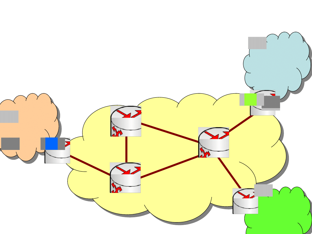
MPLS Network (1)
• The MPLS network consists of:
– Label Edge Router (LER) located on the entry
and exit points of the MPLS network
– Label Switch Routers (LSR) located inside the
MPLS network
• LER pushes an MPLS label onto an incoming
packet and pop it off the outgoing packet
according to the FEC (Forwarding Equivalence
Class)
• Packets are sent along LSP (Label Switch Paths)
between LERs and LSRs
Net IP2
Net IP2
Net IP1
Net IP1
MPLS Network
MPLS Network
MPLS Network (2)
LER2
LSR1
Net IP3
Net IP3
LSR2
LER3
LER1
LSR3

MPLS, QoS and Traffic
Engineering
• To classify a packet to FEC class IP address or
other element of the header (e.g., DSCP) can be
used
• Different FEC classes can have various QoS
parameters
• Using LSP and FEC packets between the same
pair of nodes can use diferent paths (routes)
• This enables effective traffic engineering

Network Design Problem (1)
• The network design problems includes
optimization of both routing and capacity,
therefore there are called CFA (Capacity and Flow
Assignment) problems
• Such problems are encountered by telecoms
during dimensioning the network according to
given/predicted traffic
• Usually the unicast traffic is considered
• Telecoms usually overprovision the network to
accommodate temporary traffic increase and
future clients

Network Design Problem (2)
• The network design must conform technological
constraints following from the technologies used
by the telecom (e.g., WDM, Ethernet, MPLS) as
well as business drivers (flexibility, cost,
scalability, etc.)
• Incremental network design (network
extension) problems are addressed when the
telecom is to extend the existing network to meet
growing clients’ demands considered
• Objectives of the optimization can be: cost,
survivability, QoS parameters, etc.

Objective
• How to determine network cost defined by link
capacity so that the total cost of installed links is
minimized
• Demands (traffic) are sent using MPLS
connections
• Link capacity is in modular units such as 10
Gbps links (10 Gigabit Ethernet)
• Given: network topology, demands, link module
cost

Modeling (1)
• Link-path formulation with candidate paths
• Binary variable x
dp
is 1, if demand d uses path
p; 0, otherwise
• Non-bifurcated flows and only one path can
be selected for demand d, i.e.,
p
x
dp
= 1, d = 1,2,…,D.

Modeling (2)
• Constant
edp
is 1, if link e belongs to path p
realizing demand d; 0, otherwise
• The demand volume is given by h
d
(bps)
• The flow on each link is given by formula
d
p
edp
x
dp
h
d
e = 1,2,…,E.

Modeling (3)
• The variable y
e
denotes the number of capacity
modules installed on link e
• M is the size of one module (e.g., 10 Gbps)
e
is cost of one module in link e
• The network cost is given by
e
y
e
e
• Capacity constraint - flow on each link cannot
exceed the link capacity
d
p
edp
x
dp
h
d
y
e
M e = 1,2,…,E.

Modeling (4)
objective
minimize F =
e
e
y
e
constraints
p
x
dp
= 1, d = 1,2,…,D
d
p
edp
x
dp
h
d
My
e
, e = 1,2,…,E.
x
dp
binary, y
e
integer and non-negative

Optimization
• This problem has discrete (binary and integer)
variables while the constraints and the objective
function are linear
• Thus, this is an example of a integer linear
programming problem (ILP)
• Branch-and-bound or branch-and-cut algorithms
can provide optimal result
• Various heuristics can be applied

Lecture Outline
• Introduction
• MPLS over GE Network Design
• Tunnels Optimization in MPLS Networks
• SONET/SDH Protection
• Dimensioning of Overlay Networks for P2P
Multicasting
• Access Point Location in WLANs
• Routing and Wavelegth Assignment in Optical
Networks
• Concluding Remarks

Objective
• How to carry different traffic classes in an MPLS
network through the creation of tunnels in such a
way that the number of tunnels on each MPLS
router/link is minimized and load balanced?
• Given: network topology, link capacity, demands,
candidate paths

Modeling (1)
• Let identifier d=1,2,…,D denote a demand
(associated with a node pair and a traffic class)
• Demand d that requires bandwidth h
d
and is to
be routed in the network
• Demand h
d
can be carried over multiple tunnels
from ingress to egress MPLS label-edge-router
(LER) denoted by p=1,2,…,P
d
• The fraction of the demand volume for demand d
to be carried on tunnel p is denoted as x
dp
• We then have the demand constraint
p
x
dp
= 1, d = 1,2,…,D.

Modeling (2)
• Since a flow can have very small fraction, we
propose to set a lower bound on the fraction of a
flow on a path
• We use a positive quantity ε to be the lower
bound on fraction of flow on a tunnel (path)
• We use the binary variable u
dp
= 1 to denote
selection of a tunnel if the lower bound is
satisfied (and 0, otherwise)
• We introduce the following two relations
εu
dp
x
dp
h
d
, d = 1,2,…,D p = 1,2,…,P
d
x
dp
u
dp
, d = 1,2,…,D p = 1,2,…,P
d
.

Modeling (3)
• Capacity constraint on link e (
edp
is 1, if link
e belongs to path p realizing demand d; 0,
otherwise)
d
h
d
p
edp
x
dp
c
e
, e = 1,2,…,E.
• The number of tunnels on link e will be
d
p
edp
u
dp
.
• Let r denote the maximum number of tunnels
on a link
d
p
edp
u
dp
r, e = 1,2,…,E.

Modeling (4)
objective
minimize F = r
constraints
p
x
dp
= 1, d = 1,2,…,D
d
h
d
p
edp
x
dp
c
e
, e = 1,2,…,E
εu
dp
x
dp
h
d
, d = 1,2,…,D p = 1,2,…,P
d
x
dp
u
dp
, d = 1,2,…,D p = 1,2,…,P
d
d
p
edp
u
dp
r, e = 1,2,…,E.
x
dp
continuous and non-negative, u
dp
binary, r
integer

Optimization
• This problem has both continuous and discrete
variables while the constraints and the objective
function are linear
• Thus, this is an example of a mixed-integer linear
programming problem (shortly, MIP problem)
• Branch-and-bound or branch-and-cut algorithms
can provide optimal result
• Various heuristics can be applied

Lecture Outline
• Introduction
• MPLS over GE Network Design
• Tunnels Optimization in MPLS Networks
• SONET/SDH Protection
• Dimensioning of Overlay Networks for P2P
Multicasting
• Access Point Location in WLANs
• Routing and Wavelegth Assignment in Optical
Networks
• Concluding Remarks

SONET/SDH
• Synchronous Optical Networking (SONET) or
Synchronous Digital Hierarchy (SDH) are
multiplexing protocols that transmit multiple streams
over fibers
• Lower rates can also be transferred using an
electrical interface
• SONET is used in the USA and Canada and SDH in the
rest of the world
• SONET/SDH provides essential protocol neutrality
and transport-oriented features
• SONET/SDH can be used with various technologies,
e.g., ATM (Asynchronous Transfer Mode), Ethernet

SONET/SDH Designations and
Bandwidths
SONET
Optical
Carrier Level
SONET Frame
Format
SDH level and
Frame Format
Payload
bandwidth
(kbps)
Line Rate
(kbps)
OC-1
STS-1
STM-0
50,112
51,840
OC-3
STS-3
STM-1
150,336
155,520
OC-12
STS-12
STM-4
601,344
622,080
OC-24
STS-24
–
1,202,688
1,244,160
OC-48
STS-48
STM-16
2,405,376
2,488,320
OC-192
STS-192
STM-64
9,621,504
9,953,280
OC-768
STS-768
STM-256
38,486,016
39,813,120
OC-3072
STS-3072
STM-1024
153,944,064
159,252,480

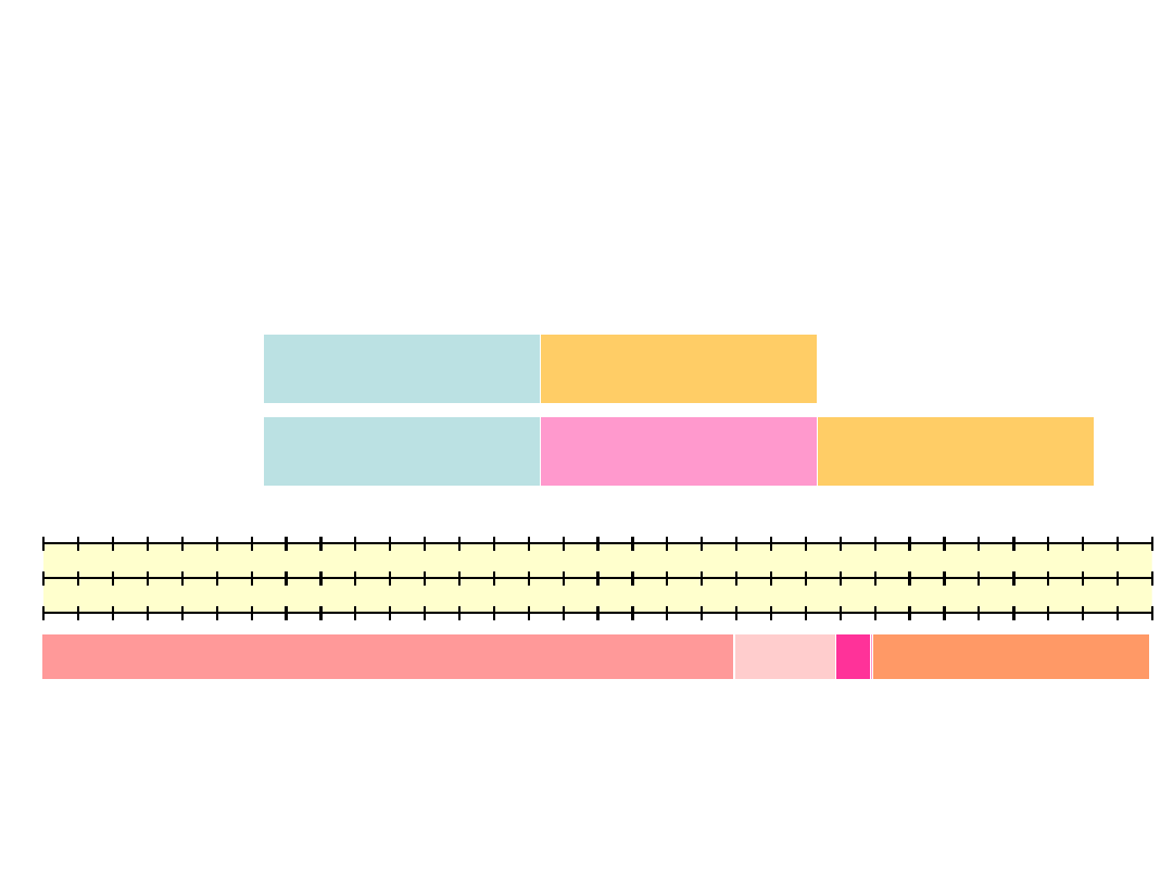
Automatic Protection
Switching
• APS (automatic protection switching), also
known as 1+1 is one of protection method used
in SDH/SONET
• The traffic is transported along both the working
and backup lightpath, then the signal quality is
then compared at the destination node and the
receiver selects the better one
• The most desirable goal of survivable networks is
to keep any interruption of carrier signal flows to
50 ms or less – APS method can assure the
duration of outage time below 50 ms
Example
2
1
3
4
12
11
10
8
7
6
9
Source
node
Destination
node
Working
path
5
1
7
Backup
path

Objective
• How to determine SDH/SONET network cost
defined by link capacity so that the total cost of
installed links is minimized
• The network is protected by APS method
• Given: network topology, demands, candidate
pairs of disjoint paths, link module cost

Modeling (1)
• Link-path formulation
• For each demand there are candidate pairs of
failure-disjoint paths p = 1,2,…,P
d
• Working path p for demand d is denoted as w
dp
,
the corresponding backup path is given by b
dp
• Constant
edp
is 1, if link e belongs to working
path w
dp
; 0, otherwise
• Constant
edp
is 1, if link e belongs to backup
path b
dp
; 0, otherwise

Modeling (2)
• Integer variable x
dp
indicates the number of
demand d circuit modules (e.g., STM-4) that
use path p; 0, otherwise
• The volume of demand d is given by h
d
, therefore
p
x
dp
= h
d
, d = 1,2,…,D.
• The flow on link e related to working paths is
d
p
x
dp
edp
, e = 1,2,…,E.
• The flow on link e related to backup paths is
d
p
x
dp
edp
, e = 1,2,…,E.

Modeling (3)
• The variable y
e
denotes the number of capacity
modules installed on link e
• M is the size of one module (e.g., given STM-4)
e
is cost of one module in link e
• The network cost is given by
e
y
e
e
• Capacity constraint - flow on each link cannot
exceed the link capacity
d
p
x
dp
(
edp
+
edp
) y
e
M, e = 1,2,…,E.

Modeling (4)
objective
minimize F =
e
e
y
e
constraints
p
x
dp
= h
d
, d = 1,2,…,D
d
p
x
dp
(
edp
+
edp
) y
e
M, e = 1,2,…,E.
x
dp
, y
e
integer and non-negative

Optimization
• This problem has discrete (integer) variables
while the constraints and the objective function
are linear
• Thus, this is an example of a integer linear
programming problem (ILP)
• Branch-and-bound or branch-and-cut algorithms
can provide optimal result
• Various heuristics can be applied

Lecture Outline
• Introduction
• MPLS over GE Network Design
• Tunnels Optimization in MPLS Networks
• SONET/SDH Protection
• Dimensioning of Overlay Networks for P2P
Multicasting
• Access Point Location in WLANs
• Routing and Wavelegth Assignment in Optical
Networks
• Concluding Remarks

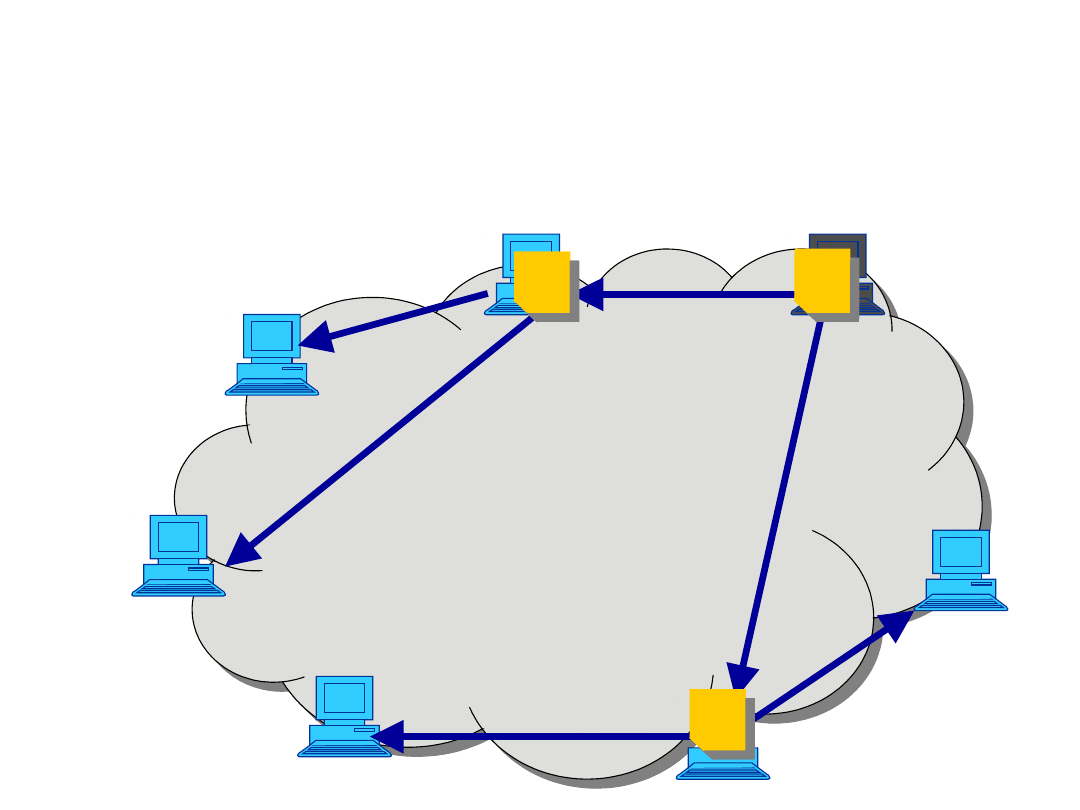
P2P Multicasting and Overlays
(1)
• Overlay is a virtual network built on the top of
an existing network (e.g., Internet)
• The underlying physical network provides
point-to-point connectivity including routing
• Overlay P2P multicasting (application-layer
multicast) uses a multicast delivery tree
constructed among peers (end hosts) of the
overlay
• Different to traditional IP multicast, the
uploading (non-leaf) nodes in the tree are
normal end hosts

P2P Multicasting and Overlays
(2)
• Peers are connected to the overlay network,
which is considered as an overprovisioned
cloud - capacity constraints are set only on access
links
• The graph is fully connected, i.e. each peer can
connect to any other peer
• The content to be distributed through P2P
multicasting can be divided into two categories:
– Elastic content (e.g. data files)
– Streaming content with specific bit rate requirements
(e.g. media streaming)
Example
1
2
3
4
5
6
7

Objective
• Minimize the overlay network cost
• The network is used for P2P multicasting of
content with a particular streaming rate
• Network cost is defined as the cost of selected
access links
• Each peer that wants to particpate in the system
has some background traffic

Modeling (1)
• The overlay network consists of V peers (nodes)
indexed by v
• For each peer we are given constants a
v
and b
v
denoting, respectively, download and upload
background traffic given in kbps
• One peer is the root of streaming and denoted
by r
v
= 1
• Each peer is connected to the network using an
access link selected from the candidate links of
a given ISP (Internet Service Provider) indexed by
k

Modeling (2)
• Let
vk
denote the cost of link type k for node v
(Euro/month)
• d
vk
is the download capacity of link type k for node
v (kbps)
• u
vk
is upload capacity of link type k for node v (kbps)
• Binary variable y
vk
is 1, if if node v is connected to the
overlay network by a link of type k; 0 otherwise
(binary)
• The download capacity of node v is
k
y
vk
d
vk
• The upload capacity of node v is
k
y
vk
u
vk
• The network cost is given by
v
k
y
vk
vk

Modeling (3)
• The volume of streaming rate is denoted by Q
(kbps)
• Each node must have enough download
capacity to receive the streaming Q and
background traffic a
v
, i.e.,
k
y
vk
d
vk
(a
v
+ Q), v = 1,2,…,V.
• Each node must have enough upload capacity
to transmit background traffic b
v
, i.e.,
k
y
vk
u
vk
b
v
, v = 1,2,…,V.

Modeling (4)
• The summary upload of the overlay network
should enable streaming of Q kbps to each peer
• Thus, the overall upload residual capacity
given by
v
(
k
y
vk
u
vk
– b
v
)
must exceed (V – 1)Q
(we take into account the background traffic and
there are (V – 1) receiving peers)
• Let
denote a dimensioning scaling factor
• In the model we introduce the following
constraint to dimensioning the network for P2P
streaming
v
(
k
y
vk
u
vk
– b
v
)
(V – 1)Q

Modeling (5)
objective
minimize F =
v
k
y
vk
vk
constraints
k
y
vk
= 1, v = 1,2,…,V
k
y
vk
d
vk
(a
v
+ Q), v = 1,2,…,V
k
y
vk
u
vk
b
v
, v = 1,2,…,V
v
(
k
y
vk
u
vk
– b
v
)
(V – 1)Q.
y
vk
binary

Optimization
• This problem has binary variables while the
constraints and the objective function are linear
• Thus, this is an example of a integer linear
programming problem (ILP)
• Branch-and-bound or branch-and-cut algorithms
can provide optimal result
• Various heuristics can be applied

Lecture Outline
• Introduction
• MPLS over GE Network Design
• Tunnels Optimization in MPLS Networks
• SONET/SDH Protection
• Dimensioning of Overlay Networks for P2P
Multicasting
• Access Point Location in WLANs
• Routing and Wavelegth Assignment in Optical
Networks
• Concluding Remarks

WiFi (1)
• WiFi (Wireless Fidelity) uses standard proposed
by IEEE 802.11
• WiFi can be used in the following modes:
– IBSS (Independent Basic Service Set) ad hoc
network
– BSS (ang. Basic Service Set) infrastructure
network with one access point
– ESS (ang. Extended Service Set) infrastructure
network with multiple access point

WiFi (2)
• WiFi uses two frequency ranges:
– 2.4 Ghz, ISM (Industry, Science, Medicine)
– 5 GHz, UNII (Unlicensed National Information
Infrastucture)
• WiFi clients (laptops, smart phones, desktops) are
connected to an access point that provides the
radio connectivity
• The most popular versions of WiFi are IEEE
802.11g, 802.11a, 802.11n
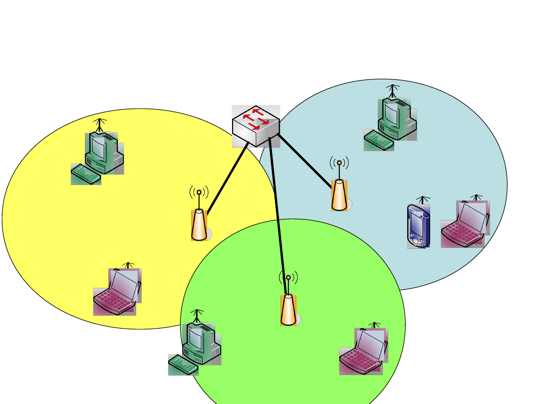
BSS1
Example
BSS2
BSS3

Objective
• Select location of WiFi access points over
candidate locations to maximize the total single-
user throughput overall all test points
• Given: candidate locations of access points, test
points, throughput for each pair of test point and
location

Modeling (1)
• Let identifier a = 1,2,…,A denote a set of
candidate AP (access point) locations
• Let index t = 1,2,…,T denote a set of TP (test
point), denoting potential users
• For each a we define a serving range, so that
TPs (test point) within the serving range of an AP,
let s = 1,2,…,S
a
be a set of of APs for which TP t is
within serving range
• Constant
at
denotes the throughput (quality of
signal) of TP t connected to AP a

Modeling (2)
• Binary variable z
a
is 1, if AP is installed in
location a; 0, otherwise
• There is a limit M on maximum number of
installed APs
a
z
a
M.
• Binary variable x
at
is 1, if TP t is assigned to AP
installed in location a; 0, otherwise
• The TP can be assigned only to an installed AP
(i.e., z
a
= 1)
x
at
z
a
, a = 1,2,…,A t = 1,2,…,T.

Modeling (3)
• Each TP can be assigned to maximum one AP
a
x
at
1, t = 1,2,…,T.
• The system throughput is calculated as
a
t
x
at
at

Modeling (4)
objective
maximize F =
a
t
x
at
at
constraints
x
at
z
a
, a = 1,2,…,A t = 1,2,…,T
a
x
at
1, t = 1,2,…,T
a
z
a
M
z
a
, x
at
binary

Optimization
• This problem has binary variables while the
constraints and the objective function are linear
• Thus, this is an example of a integer linear
programming problem (ILP)
• Usually the number of candidate APs is small,
therefore branch-and-bound or branch-and-cut
algorithms can provide optimal result in
relatively small time
• Various heuristics can be applied

Lecture Outline
• Introduction
• MPLS over GE Network Design
• Tunnels Optimization in MPLS Networks
• SONET/SDH Protection
• Dimensioning of Overlay Networks for P2P
Multicasting
• Access Point Location in WLANs
• Routing and Wavelegth Assignment in Optical
Networks
• Concluding Remarks

Optical Networks
• WDM (Wavelength Division Multiplexing) is
an optical technology, which multiplexes multiple
optical signals on a single optical fiber by using
different wavelengths (colors) of laser light to
carry different signals
• WDM is a connection-oriented technique, since
the whole signal is transmitted along one path
• Optical devices mostly cannot covert the
wavelength, therefore the whole connection must
use the same color (no wavelength
conversion)

Routing and Wavelength
Assignment
• Routing and Wavelength Assignment (RWA)
the capacity of each link is given
• It has been proven to be a NP-complete
problem
• Two possible objectives:
– Maximal capacity given, i.e., maximize routed
traffic (throughput)
– Offered traffic given, i.e., minimize wavelength
requirement

Objective
• Minimize the number of wavelengths
• Given: network topology, link capacity, demands
(lightpaths), no wavelength conversion

Modeling (1)
• Let d denote a demand defined as a node pair s
d
and t
d
• Demand d that requires h
d
connections
(lightpaths) to be routed in the network
• Let a
ev
= 1, if link e originates at node v; 0,
otherwise
• Let b
ev
= 1, if link e terminates in node v; 0,
otherwise
denotes the number of wavelengths per fiber
• λ is a wavelength index (λ = 1,2,…,
)

Modeling (2)
• Single path routing (non-bifurcated flows)
• There is not wavelength conversion, i.e., the
whole path of the connection must use the same
wavelegth
• Binary variable x
dλ
is 1, if demand d uses
wavelength λ; 0, otherwise
• Binary variable x
edλ
is 1, if demand d uses
wavelength λ on link e; 0, otherwise
• Classical multicommodity formulation and
additional layer for each wavelength

Modeling (3)
• Flow conservation constraints
e
a
ev
x
edλ
–
e
b
ev
x
edλ
= x
dλ
, if v = s
d
v = 1,2,…,V
d = 1,2,…,D λ = 1,2,…,
e
a
ev
x
edλ
–
e
b
ev
x
edλ
= –x
dλ
, if v = t
d
v = 1,2,…,V
d = 1,2,…,D λ = 1,2,…,
e
a
ev
x
edλ
–
e
b
ev
x
edλ
= 0, if v s
d
,t
d
v = 1,2,…,V
d = 1,2,…,D λ = 1,2,…,
.
• The whole demand h
d
must be satisifed, i.e.,
there must h
d
ligthpaths for each demand
λ
x
dλ
= h
d
, d = 1,2,…,D.

Modeling (3)
• Binary variable x
λ
is 1, if wavelength λ is used; 0
otherwise.
• Variable x
λ
is defined by the following constraint
x
dλ
x
λ
, d = 1,2,…,D λ = 1,2,…,
.
• The clash constraint expresses that no two
lightpaths going through the same fiber link can
use the same wavelength
d
x
edλ
x
λ
, e = 1,2,…,E λ = 1,2,…,
.
• The number of wavelentghs used in the network
is given by
λ
x
λ

Modeling (4)
objective
minimize F =
λ
x
λ
constraints
e
a
ev
x
edλ
–
e
b
ev
x
edλ
= x
dλ
, if v = s
d
v = 1,2,…,V
d = 1,2,…,D λ = 1,2,…,
e
a
ev
x
edkλ
–
e
b
ev
x
edkλ
= –x
dλ
, if v = t
d
v = 1,2,…,V
d = 1,2,…,D λ = 1,2,…,
e
a
ev
x
edkλ
–
e
b
ev
x
edkλ
= 0, if v s
d
,t
d
v = 1,2,…,V
d = 1,2,…,D λ = 1,2,…,

Modeling (5)
constraints
λ
x
dλ
, = h
d
, d = 1,2,…,D
x
dλ
x
λ
, d = 1,2,…,D λ = 1,2,…,
d
x
edλ
x
λ
, e = 1,2,…,E λ = 1,2,…,
.
X
edλ
, x
dλ
, x
λ
binary

Optimization
• This problem has binary variables while the
constraints and the objective function are linear
• Thus, this is an example of a integer linear
programming problem (ILP)
• Branch-and-bound or branch-and-cut algorithms
can provide optimal result
• Various heuristics can be applied, including
graph coloring methods

Lecture Outline
• Introduction
• MPLS over GE Network Design
• Tunnels Optimization in MPLS Networks
• SONET/SDH Protection
• Dimensioning of Overlay Networks for P2P
Multicasting
• Access Point Location in WLANs
• Routing and Wavelegth Assignment in Optical
Networks
• Concluding Remarks

Concluding Remarks
• Most of real network problems can be modeled
using integer and/or continuous modeling
• Details of the model follow from assumptions
and constraints of the considered technology
• The network traffic is usually modeled by
multicommodity flows
• More the model is closed to technology and
device constraints, more it becomes complicated
and harder to solve

Further Reading
• Pióro M. , Medhi D. , Routing, Flow, and Capacity Design in
Communication and Computer Networks, Morgan Kaufman Publishers
2004
• Jaumard, B., Meyer, C., Thiongane, B.: ILP formulations for the routing
and wavelength assignment problem: Symmetric systems. In: Resende,
M., Pardalos, P. (eds.) Handbook of Optimization in
Telecommunications, pp. 637-677. Springer, Heidelberg, 2006
• Grover W. , Mesh-based Survivable Networks: Options and Strategies
for Optical, MPLS, SONET and ATM Networking, Prentice Hall PTR, Upper
Saddle River, New Jersey, 2004
• Walkowiak K., Dimensioning of Overlay Networks for P2P Multicasting,
12th IEEE/IFIP Network Operations and Management Symposium NOMS
2010, pp. 805-809
• Bosio S. et al., Mathematical Optimization Models for WLAN Planning,
In: Koster A. Munoz X., (eds.) Graphs And Algorithms In
Communication Networks: Studies In Broadband, Optical, Wireless And
Ad Hoc Networks, Springer, 2010
Document Outline
- Slide 1
- Slide 2
- Slide 3
- Slide 4
- Slide 5
- Slide 6
- Slide 7
- Slide 8
- Slide 9
- Slide 10
- Slide 11
- Slide 12
- Slide 13
- Slide 14
- Slide 15
- Slide 16
- Slide 17
- Slide 18
- Slide 19
- Slide 20
- Slide 21
- Slide 22
- Slide 23
- Slide 24
- Slide 25
- Slide 26
- Slide 27
- Slide 28
- Slide 29
- Slide 30
- Slide 31
- Slide 32
- Slide 33
- Slide 34
- Slide 35
- Slide 36
- Slide 37
- Slide 38
- Slide 39
- Slide 40
- Slide 41
- Slide 42
- Slide 43
- Slide 44
- Slide 45
- Slide 46
- Slide 47
- Slide 48
- Slide 49
- Slide 50
- Slide 51
- Slide 52
- Slide 53
- Slide 54
- Slide 55
- Slide 56
- Slide 57
- Slide 58
- Slide 59
- Slide 60
- Slide 61
- Slide 62
- Slide 63
- Slide 64
- Slide 65
- Slide 66
- Slide 67
- Slide 68
- Slide 69
- Slide 70
Wyszukiwarka
Podobne podstrony:
ExampleExam US N(02 03)
Technologia mięsa, Cwiczenie II Dasiewicz 03-2006, Wędliny podrobowe - pojęcie zbiorcze, obejmujące
03 Przebieg procesu technologicznego i kwas mlekowy
Identyfikacja Procesów Technologicznych 03.Obiekt oscylacyjny
PKMT pytania 03, POLITECHNIKA ŚLĄSKA Wydział Mechaniczny-Technologiczny - MiBM POLSL, Inżynierskie,
03 Zniewolenie ludzi technologią mikroczipu RFID
spr 03, Ochrona środowiska, Technologie wody i ścieków
03 a8, STUDIA PŁ, TECHNOLOGIA ŻYWNOŚCI I ŻYWIENIA CZŁOWIEKA, ROK I, SEM 2, FIZYKA 2
POMIARY POŚREDNIE, Technologia maszyn, 03. Pomiary
Wykład 1-10.03.2011, Notatki UTP - Zarządzanie, Semestr II, Technologie informacyjne
03 Topologie, technologieid 4510 ppt
03.10.2010, Studia, TECHNOLOGIA INFORMACYJNA
kmp example 03
#03 OB podstawowe obciazenia technologiczne i montazowe PB 82 B 02003
Tworzenie wykresów w arkuszu kalkulacyjnym EXCEL, do uczenia, materialy do nauczania, rok2010-2011,
03. rysunek wykonawczy, Politechnika Lubelska, Studia, Studia, Sprawka 5 semestr, technologia maszyn
INŻYNIERIA REAKTORÓW CHEMICZNYCH (2 termin - zadania) - 9.03.2012, PK - technologia chem, Rok V, Rea
03 właściwości ok, Technologia chemiczna pw, 1rok, chemia kolosy egz
więcej podobnych podstron