327
g
Digital Energy
Special Function & Contr
ol
•
Flexible control device for distribution applications
•
Advanced automation capabilities for providing customized
protection and control solutions
•
Human machine interface (HMI) - graphical LCD,
programmable buttons, and easy keys for selecting setting
menus, and submenus.
•
Minimize replacement time - Modular with card draw-out
construction
•
Reduce troubleshooting time and maintenance costs -
IRIG-B and SNTP time synchronization, event reports,
waveform capture, data logger
•
Advanced automation capabilities for providing customized
control solutions
•
Reduced relay to relay wiring and associated installation
costs through high-speed inter-relay communications
•
Simplified system integration with communications
supporting serial and Ethernet interfaces and multiple
protocols
•
Reduced relay to relay wiring and associated installation
costs through high-speed inter-relay communications
•
Embedded IEC61850 Protocol (optional)
•
Primary control for distribution on solidly grounded, high
impedance grounded or resonant (Peterson Coil) grounded
systems
•
Bus blocking/Interlocking schemes
•
Throw over schemes (bus transfer scheme applications)
•
Load shedding schemes based on voltage and frequency
elements
•
Programmable Logic Control
•
Sophisticated software for configuration and commissioning
•
Document and software archiving
•
EnerVista™ Integrator providing easy integration of data in the
C650 into new or existing monitoring and control systems
EnerVista™ Software
Control
•
Four-shot autorecloser with synchronism check
•
Breaker control
•
Synchrocheck - V, , & Hz
•
Up to 64 Programmable digital inputs and up to 16 digital
outputs
•
Trip Circuit Supervision
FEATURES
C650
BAY CONTROL &
MONITORING SYSTEM
Substation hardened
Programmable logic controller
FEATURES
APPLICATIONS
KEY BENEFITS
Monitoring & Metering
•
Breaker operation
•
Event recorder - 479 Events
•
High resolution oscillography and Data Logger, with
programmable sampling rate
•
Metering: V I Hz W VA PF
•
Demand: Ia , Ib , Ic , Ig, Isg, I2, MW, MVA
•
Configurable graphical HMI interface
•
Alarm Panel
www.GEDigitalEnergy.com
C650
Bay Control & Monitoring System
328
Special Function & Contr
ol
Control
The C650 provides high speed control for
bay control applications, including:
Autoreclosurer
This function is applicable to three-pole
tripping schemes and single breaker
applications. Four reclosing “shots“ are
possible prior to locking out, each with an
independent time setting. Auto reclosure
outputs can be used to modify circuit
protection settings between shots.
Synchronism Check
One synchronism check element is
available. The algorithm allows breaker
close time compensation to optimize
close conditions. The element monitors
maximum difference in voltage magnitudes
( V), phase angles ( ), and frequencies
( f) as well as the dead source condition.
Advanced Automation
The C650 incorporates advanced
automation features including powerful
programmable logic, communication, and
SCADA capabilities that far surpass what is
found in the average controller relay. The
C650 integrates seamlessly with other GE
Multilin relays for complete system control.
C650 Logic Configuration
C650 Logic Configuration is the powerful
programming logic engine that provides
the ability of creating customized
protection and control schemes thereby
minimizing the need, and the associated
costs, of auxiliary components and wiring.
Inputs and Outputs
A choice of 16 to 64 inputs and 0 to 16
outputs are available. Digital inputs may
be user defined with a separate debounce
and chatter time. Programmable “quasi“
analog input levels allow the use of
different voltage levels in the same model
via setting the requested thresholds.
EnerVista™ software allows easy
configuration of all the interlocking and
switching sequences. A graphic HMI
interface provides access to monitoring,
metering and alarm panel screens.
Virtual Inputs/Outputs
Traditionally, relay logic has been
relatively limited. Use virtual inputs
and outputs in conjunction with the
programmable logic capabilities of the
C650 for unusual applications involving
interlocks, blocking, or supervisory
functions, to minimize the requirement for
auxiliary components and wiring while
making more complex schemes possible.
The virtual inputs and outputs are digital
signals associated with the C650 internal
logic. Virtual inputs include signals
generated remotely via communications.
The virtual outputs are outputs of
programmable logic equations used to
customize the device. Virtual outputs can
also serve as inputs to programmable logic
equations.
CAN BUS Remote I/O (CIO)
The C650 can be ordered with up to four
additional communication cards on the
rear. Besides two identical ports, COM1
and COM2, the cards may incorporate a
port for CAN BUS communications used to
connect the Remote CAN BUS I/O module
(CIO Module). Use the CIO Module to double
the number of I/Os of the C650, when the
maximum number of I/Os available inside
the relay (up to 64 inputs and 16 outputs) is
not sufficient to meet the needs of specific
applications.
In addition to increasing the number of
I/Os, the CIO Module allows the C650
to monitor signals located at a remote
location with only a connection between
both devices, resulting in significant
savings in installation costs.
Transducer Inputs
dcmA inputs are available to monitor
system parameters such as temperature,
vibration, pressure, wind speed, and flow.
Remote I/O
The remote I/O feature provides a means
of sharing digital point state information
between C650s or other IEC61850
compliant IEDs or controllers. The remote
outputs interface seamlessly to the remote
inputs of other C650 devices via the
IEC61850 GSSE messaging. User secure
peer-to-peer communications to develop
complex schemes in distributed logic and
I/Os.
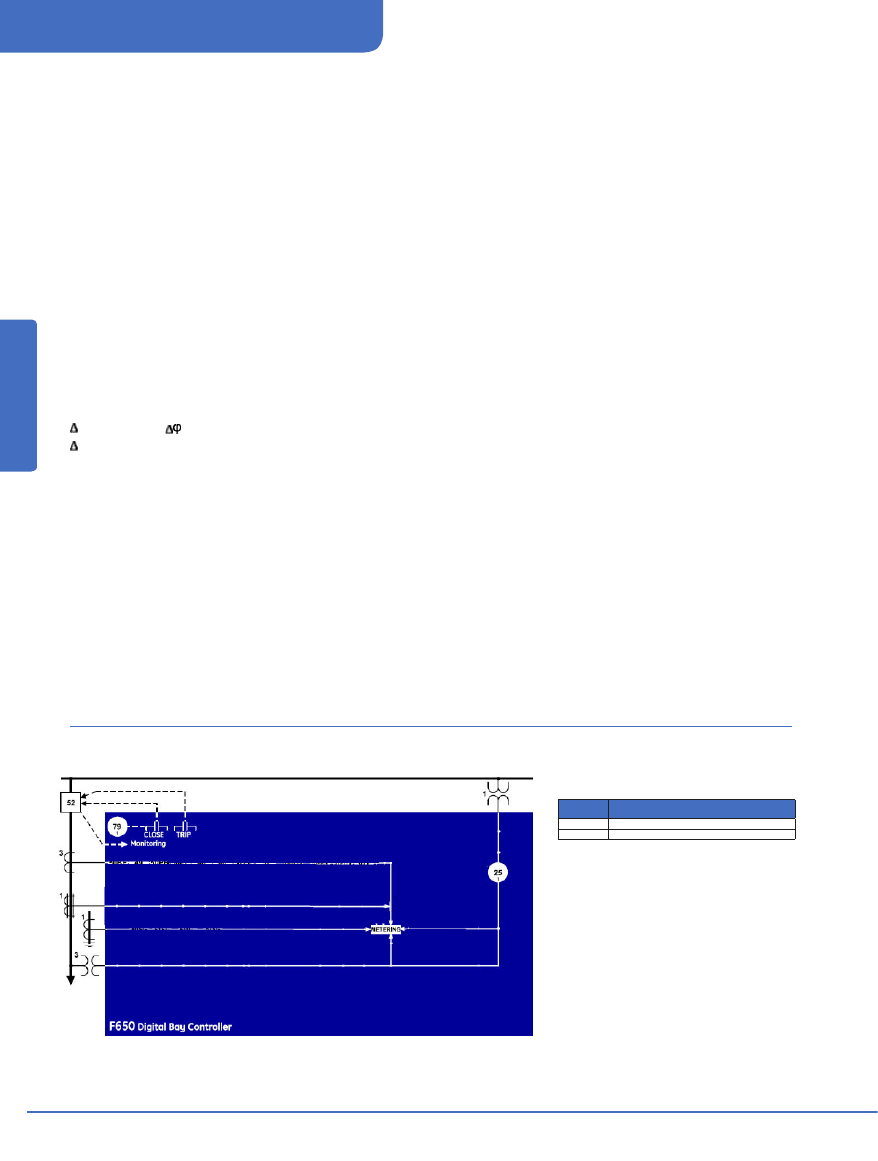
Functional Block Diagram
Device
Number
Function
25
Synchrocheck
79
Autorecloser
ANSI Device Numbers & Functions

www.GEDigitalEnergy.com
329
C650
Bay Control & Monitoring System
Special Function & Contr
ol
Monitoring and Metering
The C650 provides advanced monitoring
and metering that includes:
Trip Circuit Monitoring
C650 can be used to monitor the integrity
of both the breaker trip and closing
coils and circuits. The supervision inputs
monitor both the battery voltage level,
while the outputs monitor the continuity of
the trip and/or closing circuits, by applying
a small current through the circuits.
Basic Metering
Metered values include:
• Current: Ia, Ib, Ic, In, Ig, Isg
• Phase-to-phase and phase-to-ground
voltages for bus and line: Van, Vbn, Vcn,
Vbb, Vab, Vbc, Vca
• Active power (per-phase and total): Wa,
Wb, Wc, W
• Reactive power (per-phase and total):
VAra, VArb, VArc, VAr
•
Total active, reactive and apparent
energy: MWh, MVArh, MVah
•
Power factor (per-phase and total)
•
Frequency
•
Demand
Ia, Ib, Ic, Ig, Isg, Va, Vb, Vc and Vx signals are
available locally and remotely and can be
stored in the oscillography record or data
logger.
Event Recording and Oscillography
The C650 is capable of storing 479 time-
tagged events (1 ms tagging), to help
with trouble shooting. The trigger point,
the channels, and sampling rate of the
oscillography files are user programmable
features. Up to five seconds at maximum
sample rate can be stored.
Breaker Arcing Current (I2t)
The relay estimates the total interrupted
current as an accumulation of the RMS
current measured during the time period
taken to open the breaker after a trip.
It calculates the per-phase wear on the
breaker contacts to establish a threshold.
When the breaker maintenance threshold
is exceeded the relay can be set to trigger
an alarm.
Communications
The C650 includes up to three communication
ports that operate simultaneously.
Redundant ports are also available for
special applications. C650 features an
RS232 front port (COM2) and a choice
of rear RS485, plastic/glass fiber optics
(COM1 and COM2). Additionally, this
module may incorporate a port for CAN bus
communications, used for the connection
to the remote CAN BUS I/O module. C650
COM3 features 10/100 BaseTX and 100
Base FX single or redundant Ethernet ports.
Protocols supported by the C650
include IEC61850, DNP 3.0, Modbus RTU,
ModBus TCP/IP and IEC 60870-5-104.
These protocols make it easy to connect
to a Utility automation system and are
integrated into the C650, eliminating
the need for external protocol converter
devices.
Security
Independent passwords for protection and
control allow restricting access via keypad
and display, or EnerVista
™
software.
Interoperability With Embedded
IEC61850 Protocol
IEC61850 is the new international
standard for information exchange and
interoperability between intelligent
devices within a substation. Use the C650
with IEC61850 to lower the costs and
simplify the engineering, commissioning,
operating, and maintenance associated
with substation protection and control
applications. IEC61850 is built on over
7 years of GE leadership in UCA 2.0
implementation.
IEC61850 allows for the seamless
connection of IEDs from multiple vendors.
In addition to device interoperability, these
protocols are designed to control the
substation via a LAN instead of through
discrete wiring to an RTU. Peer-to-peer
communication over Ethernet enables
distributed control with several IEDs and
eliminates the need for an RTU to remote
SCADA master. High-speed message
transfer eliminates the need for large and
costly hard-wired interconnection.
EnerVista™ Software
The EnerVista™ Suite is an industry-leading
set of software programs that simplifies
every aspect of using the C650 relay. The
EnerVista™ suite provides all the tools to
monitor the status of your the protected
asset, maintain the relay, and integrate
information measured by the C650 into DCS
or SCADA monitoring systems. Convenient
COMTRADE and Sequence of Events viewers
are an integral part of the 650 Setup
software included with every C650 relay,
to carry out postmortem event analysis to
ensure proper protection system operation.
EnerVista™ Launchpad
EnerVista™ Launchpad is a powerful
software package that provides users with
all of the setup and support tools needed
for configuring and maintaining GE Multilin
products. The setup software within
Launchpad allows configuring devices in
real-time by communicating using serial,
Ethernet, or modem connections, or offline
by creating setting files to be sent to devices
at a later time.
Included in Launchpad is a document
archiving and management system that
ensures critical documentation is up-to-date
and available when needed. Documents
made available include:
• Manuals
• Application Notes
• Guideform Specifications
• Brochures
• Wiring Diagrams
• FAQ’s
• Service Bulletins
Viewpoint Monitoring
Viewpoint Monitoring is a simple-to-use
and full-featured monitoring and data
recording software package for small
systems. Viewpoint Monitoring provides a
complete HMI package with the following
functionality:
• Plug-&-Play Device Monitoring
• System Single-Line Monitoring &
Control
• Annunciator Alarm Screens
• Trending Reports
• Automatic Event Retrieval
• Automatic Waveform Retrieval
www.GEDigitalEnergy.com
C650
Bay Control & Monitoring System
330
Special Function & Contr
ol
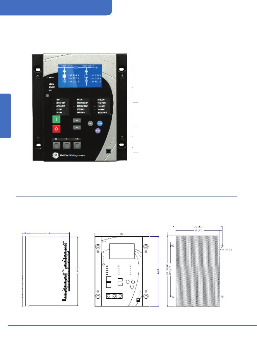
User Interface
Dimensions
The C650 uses a “shuttle“ control for ease of use. A choice of text or graphic display, and up to five configurable keys are available for frequently
performed control functions. Up to 15 programmable LEDs are available. The C650 can incorporate (option “N” for the second position of the
ordering code) a Graphical display with IEC Symbols.
Display
• Graphic 16x40 or text 4x20 LCD display
• Fluorescent backlight to improve visibility
LEDs
• Multicolor programmable LEDs with label panel
• Local/Remote/Off pushbutton with LEDs
Keypad & Shuttle
• Local/Remote/Off pushbutton withLEDs
• Key control for easy navigation
• Ergonomic programmable keys
Front Port
• Electrically isolated front USB communication port
SIDE VIEW
FRONT VIEW
CUTOUT
Note: all dimensions are shown in mm (inches)
PANEL MOUNTING CUTOUT
www.GEDigitalEnergy.com
331
C650
Bay Control & Monitoring System
Special Function & Contr
ol
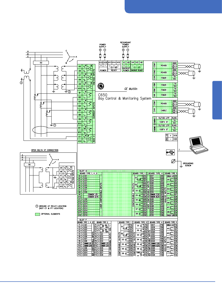
Typical Wiring Diagram

www.GEDigitalEnergy.com
C650
Bay Control & Monitoring System
332
Special Function & Contr
ol
INPUTS
CURRENT INPUTS
Rated current:
Appropriate for 1 or 5 A
LoadRelay Burden: < 0.04 Ohm
Overload:
20 A permanent
500 A during 1 second
Current Withstand:
Continuous at 20 A
1 second at 500 A for phases
and ground
1 second at 50 A for sensitive
ground
VOLTAGE INPUTS
VAC inputs do not need varistors, as the impulse test is
applied to 100% of the transformers
Metering range:
From 2 to 275 Vac
LoadRelay Burden: 0.05 VA at 120 Vac (50 or 60 Hz)
Voltage withstand: 260 Vac permanent
Continuous at 275 V to neutral
420 Vac during 1 min/hr at 420 to
neutral
DIGITAL INPUTS
Voltage Threshold: Programmable from 20 up to
230Vdc in steps of 1 V
Impedance:
> 100 kOhm
Load for voltage
supervision inputs: 2 mA + V/100 kOhm
Maximum error:
±10% setting or ± 5 V
Acknowledgement time: < 1 ms
Debounce time:
1 to 50 ms in steps of 1 ms
REMOTE INPUTS
No of input points: 32, configured from 64 incoming
bit pairs
No of remote devices: 16
Default states on loss of comms: On, Off, Latest/on,
Latest/off
ANALOG INPUTS (dcmA)
Current inputs:
0 to -1; 0 to +1; -1 to +1; 0 to 5; 0
to 10; 0 to 20, 4 to 20
Conversion range: -1 to 20 dcmA
Accuracy:
+/-0.2% of full scale
Type:
Passive
IRIG-B TIME SYNCHRONIZATION INPUT
Type:
Demodulated input (no carrier)
Formats:
B000(*) B001, B002 and B003(*)
Level:
TTL
Load:
1.5 mA
(*) Signal combinations recognized in accordance with
IRIG Standard 200-95
REAL TIME CLOCK
Accuracy:
Typical 20 ppm
Backup energy:
More than 1 week
MONITORING
TRIP/CLOSE COIL MONITORS
Detect open trip and close circuits
OSCILLOGRAPHY
Records:
Up to 20 oscillography records.
Samples:
Programmable to 4, 8, 16, 32 or 64
samples per cycle
Trigger position:
5% to 95% of total length
Trigger:
Programmable via programmable logic
Data:
5 current channels and 4 voltage
channels
Up to 16 digital channels selectable
from the available internal states
programmable through PLC
Storage:
Permanent in non volatile memory
(flash) without battery In non-volatile
memory (flash) without battery
Format:
International Standard COMTRADE
ASCII - IEEE C37.111-1999.
SNAPSHOT EVENTS
Capacity:
479 scrolling events
Labeling time tag: 1 ms using an internal clock of 100 µs
Accuracy:
1 ms (using the IRIG-B synchronization
input)
Trigger:
By pickup or dropout or operate of any
element
By change of state in a Digital
input/output change of state
By virtual inputs and control events
Storage:
Permanent in non volatile memory
(flash) without battery
CONTROL EVENTS
Capacity:
128 events programmable through PLC
Labeling time tag: 1 ms using an internal clock of 100 µs
Accuracy:
1 ms (using the IRIG-B synchronization
input)
Trigger:
By any digital signal programmable
through PLC
Alarm:
Possibility to display the event as an
alarm on the alarms panel. Information
available always through
Communications for all models and
also in HMI for models with graphical
display (M in ordering code).
Storage:
Permanent in non volatile memory
(flash) without battery
DEMAND
Channels:
9
Parameters: Ia(kA RMS), Ib(kA RMS), Ic(kA RMS),
Ig(kA RMS), Isg(kA RMS), I2 (KA),
P(MW), Q (MVAr) and S (MVA)
Current and Power Method:
Thermal Exponential, block
interval, Rolling demand
Metering Measurements: Each channel shows the
present and maximum measured
value, with date and time for the
maximum recorded value.
Samples:
5, 10, 15, 20, 30, 60 minutes.
Accuracy:
±1%
DATA LOGGER
Channels:
1 to 16
Parameters: Any of the analog Metering actual values
Samples:
1 second, 1, 5, 10, 15, 20, 30, 60
minutes.
Capacity: Fixed, (32768 measures)
METERING
CURRENT
Accuracy:
±0.5% of the reading ± 10 mA
from 0.1 to 10 A (for phases and
ground)
±1.5% of the reading ± 1 mA from
0.005 to 5 A (for sensitive ground)
±1.5% of the reading for higher
values
VOLTAGE
Accuracy:
±1% reading, from 10 to 208 V
POWER
Active:
±2,5% of the reading from power
factor ±0.8 to 1
Reactive:
±2,5% of the reading from power
factor ±0.2 to 0
Apparent:
±2,5% of the reading
ENERGY
Watts- hour (positive and negative)
Accuracy:
2,5%
Range:
±0 to 2147 MWh
Parameters:
three-phase
Updating Time:
100 ms
Var-hour (positive and negative)
Accuracy:
2,5%
Range:
±0 to 2147 MVArh
Updating Time:
100 ms
POWER FACTOR
Accuracy:
0.02
FREQUENCY
Accuracy:
±50 mHz
Accuracy angle:
2º
CONTROL
AUTORECLOSE (79)
Schemes:
Three-phase pole tripping schemes
No. of reclosing shots: Up to 4 reclose attempts
before lockout
Dead time: Independent dead time setting before
each shot adjustable between 0 and 900 s
in steps of 0.01 s
Reclaim time: 0.00 to 900.00 s in steps of 0.01 s
Condition permission: Selectable by setting
Hold time: 0.00 to 900.00 s in steps of 0.01 s
Reset time: 0.00 to 900.00 s in steps of 0.01 s
Snapshot Events: Selectable by setting
Possibility to modify protection settings after each shot
SYNCHRONISM CHECK (25)
Dead/live levels for line and bus:
0.00 to 300.00 in steps of 0.01 V
Maximum voltage difference:
2.00 to 300.00 V in steps of 0.01 V
Maximum angle difference:
2.0º to 80.0º in steps of 0.1º
Maximum frequency slip:
10 to 5000 mHz in steps of 10 mHz
Synchronism time: 0.01 to 600.00 s in steps of 0.01 s
Angle accuracy: 3º
Dead Source function: None
(DL-DB) Dead Line - Dead Bus
(LL-DB) Live Line-Dead Bus
(DL-LB) Dead Line – Live Bus
Snapshot Events: Selectable by setting
BREAKER MAINTENANCE
Kl2t BKR Ph A, B, C Cnt:
0.00 to 9999.99 in steps of 0.01 (KA)2s
BKR Openings Cnt: 0 to 9999 in steps of 1
BKR Closings Cnt: 0 to 9999 in steps of 1
BREAKER SETTINGS
Switchgear number: 1 to16
Maximum KI
2
t: 0.00 to 9999.99 in steps of 0.01 (KA)2s
KI2t integ. Time: 0.03 : 0.25 s in steps of 0.01s
Maximum openings: 0 to 9999 in steps of 1
Maximum Openings in an hour: 1 to 60 in steps of 1
Switchgear
Switchgear number: 1 to16
Switchgear: 1 to16 (configurable).
Technical Specifications

www.GEDigitalEnergy.com
333
C650
Bay Control & Monitoring System
Special Function & Contr
ol
OUTPUTS
TRIPPING CONTACTS/OUTPUT RELAYS
Permanent current Carry continous 16 A
Closing current Make and Carry for 1 second
60 A during 1 second
Opening current
0.3 A with L/R = 40 ms at 125 Vdc
0.25 A with L/R = 40 ms at 250 Vdc
REMOTE OUTPUTS
Standard output points 32
User output points 32
COMMUNICATIONS
FRONT PORT (COM2):
Type:
USB
Baude Rate:
300, 600, 1200, 2400, 4800, 9600,
38400, 57600 and 115200 bauds
Default baud rate: 19200 bauds
Protocol:
ModBus® RTU / DNP 3.0
ASYNCHRONOUS REAR PORTS:
Two COM1, COM2 (rear COM2 multiplexed with front
port)
Type:
Depending on model
Two RS485 ports
Two 1mm-plastic F.O. ports
Two multimode glass F.O. ports
with ST connectors.
PROTOCOLS:
DNP on COM1 & COM2
Serial Modbus® on COM1 & COM2
CAN PORT:
Type:
Cable or Multimode glass F.O. port
with ST connectors
Fiber Wave length: 1300 nm
Isolation:
2kV
ETHERNET PORT:
Type:
Model B:
10/100BaseTX self-negotiable
Model C:
10/100BaseTX + 100Base FX with
ST connectors
Model D:
10/100BaseTX + Double
100BaseFX with ST connectors
(physical media redundancy)
Model E:
Redundant 10/100BaseTX
Protocols:
ModBus® TCP/IP
DNP over TCP/IP and UDP/IP
IEC 60870-5-104
IEC61850
Http, ftp, tftp (allow the use of a
standard Internet browser)
NOTES:
In Models C and D, the 10/100BaseTX port is selected
by an internal switch. Two indicating LEDs for trans-
mission and reception are included
POWER SUPPLY
Options:
F range LO, LOR: DC: 24 to 48 V
H range HI, HIR: DC: 110 to 250 V
AC: 120 to 230 V
Power:
25 VA nominal, maximum 45 VA
Voltage loss hold-up time:
200 ms typical, worst case 100 ms
without unit reset
MECHANICAL CHARACTERISTICS
Metallic package in 1/2 19" rack 6 units high
Protection class IP52 (according to IEC 529)
CONTROL
Graphical display: English.
Basic display: English.
PACKAGING
Approximate weight:
Net:
11 lbs (5 kg)
Ship:
13.2 lbs (6 kg)
ENVIRONMENTAL
Temperature:
Storage: -40 to +80° C
Operation: -20 to +60° C
Humidity:
Up to 95% without condensing
APPROVALS
CE:
Conforms to EN/IEC 60255, 61010
*Specifications subject to change without notice.
TYPE TESTS
CATEGORY
STANDARD
CLASS
TEST
EMC
IEC 60255-25 EN 61000-6-4 A Conducted and
Emisivity
radiated emissions
Product IEC 60255-5
2 kV Insulation resistance -
dielectric test
IEC 60255-5
6kV .5J Impulse test
IEC 60255-11
100 ms Power supply
Voltagedips/inter-
ruptions/variations:
Mechanical IEC 60255-21-1
I Vibration test
(sinusoidal)
IEC 60255-21-2
I Shock and bump
IEC 60255-21-2
II Seismic
TYPE TESTS
CATEGORY
STANDARD
CLASS
TEST
EMC
IEC 61000-4-1 IEC 60255-22-1 III Oscillatory waves
immunity
IEC 61000-4-2 IEC 60255-22-2 IV Electrostatic dis-
charge immunity test
IEC 61000-4-3 IEC 60255-22-3 III Radiated electro-
magnetic field
disturbance test
IEC 61000-4-4 IEC 60255-22-4 IV Electrical fast transient
IEC 61000-4-5 IEC 60255-22-5 IVA Surge immunity test
IEC 61000-4-6 IEC 60255-22-6 III Conducted electro-
magnetic field
disturbance test
IEC 61000-4-8 EN 61000-4-8 IV Power frequency
magnetic field
immunity
ENV50204
III Radiated electro-
magnetic field
disturbance test -
1890 MHz.
Technical Specifications (cont’d)

www.GEDigitalEnergy.com
C650
Bay Control & Monitoring System
334
Special Function & Contr
ol
Ordering
C650
*
*
* F
* G
*
*
*
*
*
*
DESCRIPTION
C650
DIGTAL BAY MANAGEMENT DEVICE
B
Basic Display and Basic Control Functionality (See Note 1)
M
Graphical Display with Standard Symbols and Basic Control Functionality (See Note 1)
N
Graphical Display with IEC Symbols and Basic Control Functionality (See Note 1)
E
Basic Display and Enhanced Control Functionality. (See Note 1)
C
Graphical Display with Standard Symbols and Enhanced Control Functionality. (See Note 1)
D
Graphical Display with IEC Symbols and Enhanced Control Functionality. (See Note 1)
REAR SERIAL COMMUNICATIONS BOARD 1
F
None
A
Redundant RS485
P
Redundant plasticfiber optic
G
Redundant glass fiber optic
X
Redundant RS485 + fiber remote CAN bus I/O
Y
Redundant plastic fiber optic + fiber remote CAN bus I/O
Z
Redundant glass fiber optic + fiber remote CAN bus I/O
C
Cable Remote CAN Bus I/O
M
RS485 + cable Remote CAN Bus I/O
REAR ETHERNET COMMUNICATIONS BOARD 2
B
10/100 Base TX
C
10/100 Base TX + 100 Base FX
D
10/100 Base TX + Redundant 100 Base FX
E
Redundant 10/100 Base TX
I/O BOARD IN SLOT F
1
16 Digital Inputs + 8 Outputs
2
8 Digital Inputs + 8 Outputs + 2 trip/close circuit supervision circuits
4
32 Digital Inputs
5
16 Digitall Inputs + 8 Analog Inputs
I/O BOARD IN SLOT G
0
None
1
16 Digital Inputs + 8 Outputs
4
32 Digital Inputs (See Note 1)
5
16 Digital Inputs + 8 Analog Inputs (See Note 1)
AUXILIARY VOLTAGE
LO
24-48 Vdc (range 19.2 - 57.6)
HI
110- 250 Vdc (range 88 – 300)
120-230 Vac (range 96 – 250)
LOR
Redundant LO
HIR
Redundant HI
LANGUAGE
-
English/English
COMMUNICATION PROTOCOL
-
Modbus ® RTU, TCP/IP, DNP 3.0 Level 2, IEC 60870-5-104
6
IEC61850, Modbus ® RTU and TCP/IP, DNP 3.0 Level 2, IEC 60870-5-104
ENVIRONMENTAL PROTECTION
-
Without Harsh (Chemical) Environment Conformal Coating
H
Harsh (Chemical) Environment Conformal Coating
ENHANCED DISPLAY
E
Enhanced Display with Front USB port
(*) Notes:
(1) Control functionality description for basic and enhanced models. See table below
(2) The number selected for option G must be equal or higher than the number selected for option F for models including boards 4 and 5.
Ordering Note:
This order code is valid for the latest version of C650 hardware and firmware version. The older hardware and previous firmware versions are still available and may be ordered through the usual channels.
• Multilink Ethernet Switch
ML2400-F-HI-HI-A2-A2-A6-G1
• Viewpoint Maintenance
VPM-1
• Viewpoint Monitoring IEC61850
VP-1-61850
Accessories for the C650
• View Guideform specifications
• Download the instruction manual
• Review applications notes and support documents
• Buy a C650 online
• View the 650 Family brochure
Visit www.GEDigitalEnergy.com to:
110530 - V9
Ansi code
Functionality
C650 Basic
C650
Enhanced
25
Synchrocheck
X
79
Recloser
X
Metering
X
Wyszukiwarka
Podobne podstrony:
GE system monitorowania stanu maszyny online
Monitorowanie oraz identyfikacja zmian w strukturze plików systemu Windows
Monitorowanie mediów w systemie e FlowNet
Monitoring telefoniczny systemów alarmowych
Zmiany w systemie pomocy psychologiczno pedagogicznej – jak zorganizować i monitorować pracę zespołu
Systemy monitorowania bezpieczenstwem zywnosci
Dude System monitorowania sieci przy pomocy DUDE v1
Monitorowanie systemu. Dziennik wydajności, Notatki, SiS, KL.I
Monitoring sieci w systemach BSD
Wykład 4 systemy monitorowania LRIT i AIS PL
Laboratorium z Architektury systemów komputerowych, Budowa monitorów alfanumerycznych, Politechnika
klawiatury monitory drukarki myszki, Studia, WAT Informatyka 2, semestr IV, systemy wejścia-wyjścia
system monitoringu galangowska, korczynski, piekalny, wojciechowski
monitoring - opracowne, PWR Politechnika Wrocławska, Systemy Zarządzania i Monitoring Środowiska (ap
systemy VTS i monitorowania LRIT i AIS PL
OPIS SYSTEMU MONITOROWANIE ZDROWIA STRUKTURY BURJ KHALIFA
(Ćw nr 5) PA Lab KOMP SYSTEM MONITORINGU GENIE
więcej podobnych podstron