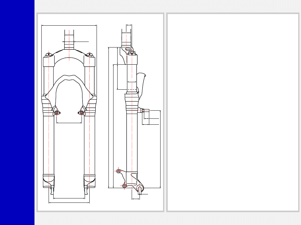
Z2
ATOM
Race
TRA
VEL 80
100
80
130
175
L.MAX=461
L.L.=451 L.MIN=371
396
Ø30
18
25
9.2
55
248.5
±
2
±
2
+0.5
0
+0.1
0
Ø30
+0.05
0
15
20
0
-0.1
+1
0
GENERAL
• Special cross-country fork whose legs are damped by a differen-
tiated system.
• Both legs use a mechanical coil spring system for compression
damping
• The right leg is also damped by a hydraulic cartridge.
• Spring pre-load adjustment (in both legs) and rebound damping
(right leg only) controlled via external top leg adjuster.
• Stanchions fitted into lower Crown by cryofit technique. Full
length bushings guarantee superior rigidity.
• Sliders and arch are an integral assembly for reduced weight and
improved rigidity.
• Parts subjected to friction are cooled and lubricated by a specially
formulated oil.
Steer tube: EASTON aluminum steer tubes available for 1 1/8”
diameter, threadless.
Crown: Forged and CNC-machined BAM
❊
aluminum alloy.
Arch: Cast magnesium alloy.
Stanchions: anodized EASTON aluminum with variable butting.
Sliders: Forged and CNC-machined BAM
❊
aluminum alloy. Left
slider equipped with disc brake adapter.
Springs: Constant pitch springs.
Slider bushing: Full length guide bushing composed of a copper
base and impregnated with an anti-friction coating.
Seals: Computer designed oil seals guarantee the highest quality
seals available.
Oil: Specially formulated oil which eliminates foaming and viscosity
breakdown while providing complete stiction-free performance.
Fork leg oil: type EBH 16 - SAE 7.5.
– right leg 90 cc,
– left leg 100 cc.
❊
❊
❊
❊
❊
BAM: Bomber Aerospace Material.
Special alloy developed from aerospace material.

Z2
ATOM
Race
GENERAL RULES
1. Where specified, assemble and disas-
semble the shock absorption system
using the M
ARZOCCHI
special tools only,
as shown in the table below.
2. On reassembling the suspension sys-
tem, always use new seals.
3. Clean all metal parts with a special,
preferably biodegradable solvent, such
as trichloroethane or trichloroethylene.
4. Before reassembling, lubricate all parts
in contact with each other using sili-
cone fat spray.
5. Always grease the conic seal rings
before reassembling.
6. Use wrenches with metric size only.
Wrenches with inch size might dam-
age the fastening devices even when
their size is similar to that of the wrenches
in metric size.
INSTRUCTIONS

Z2
ATOM
Race
FAILURES, CAUSES AND REMEDIES
This paragraph reports some failures that may occur when using the fork. It also indicates possible causes and suggests a remedy. Always
refer to this table before doing any repair work.
Oil leaking through the bottom of slider
O-ring on the cartridge seal nut and/or
pumping rod damaged
Replace the O-ring
Oil leaking through the top of slider
1. Oil seal is worn out
2. Stanchion tube is scored
3. Excessive dirt on oil seal
1. Replace oil seal
2. Replace crown/stanchions assembly,
oil seals and dust seals
3. Clean the oil seal seat and replace oil seal
Fork has not been used for some time and
is locked out
Oil seals and dust seals tend to stick to
stanchion tube
Raise dust seal and lubricate stanchion
tube, dust seal and oil seal with silicone
grease
Fork rebounds too fast even though the
adjuster is set to hardest damping position
(right leg)
Cartridge is faulty
Replace hydraulic cartridge
Excessive play of stanchions in the sliders
Pilot bushings are worn
Replace pilot bushings
FAILURES
CAUSES
REMEDIES
Adjuster position does not affect fork op-
eration
Dirt inside legs
Clean carefully and change oil

Z2
ATOM
Race
RECOMMENDATIONS FOR
MAINTENANCE
M
ARZOCCHI
forks are based on advanced
technology, supported by year-long expe-
rience in the field of professional moun-
tain biking. In order to achieve best re-
sults, we recommend to check and clean
the area below the dust seal and the
stanchion tube after each use and lubri-
cate with silicone oil.
In general, M
ARZOCCHI
forks can offer top
performance from the start. However, in
some cases a short running-in period is
required (5-10 hours) for inner adjust-
ments. This running-in period will make
fork life longer and ensure fork top per-
formance over time.
IMPORTANT: change oil at least every
100 working hours.
Polished forks should be cleaned with
bodywork polish at regular intervals in
order to preserve their original finish.
INSTALLATION
Installing the fork on a bicycle is a very
delicate operation that should be carried
out with extreme care. The installation
should always be checked by one of our
Technical Service Centers.
WARNING: Steer tube/headset
mounting and adjustment must be
carried out in compliance with the head-
set manufacturer’s instructions. Improper
installation may jeopardize the safety of
the rider.
To replace it, contact one of our Technical
Service Centers with the required tools.
WARNING: In case of improper
installation of the steer tube into the
crown, the rider might lose control of his/
her bicycle, thus jeopardizing his/her
safety.
DISC BRAKE SYSTEM ASSEMBLY
WARNING: If a disc brake sys-
tem is installed, it is absolutely for-
bidden to loosen and remove original
brake supports fixing pins. In fact, apart
from retaining Cantilever or V-brake le-
vers, they also play an important role in
securing slider bottom to slider-arch mono-
lith. If needed, replace these pins with
screws (part no. 532979QF) available
as spare parts.
Tighten the above screws to 15 Nm.
IMPORTANT: screw and pin threading
is treated to ensure hydraulic seal. Never
reuse screws and pins which have been
removed.
Assembling the brake caliper onto the
slider is a very delicate operation that
should be carried out with extreme care.
Improper assembly might overstress the
caliper supports which might break.
When installing the disc brake system, be
sure to properly follow the instructions
given by the manufacturer.
Z2
ATOM
Race
ADJUSTMENTS
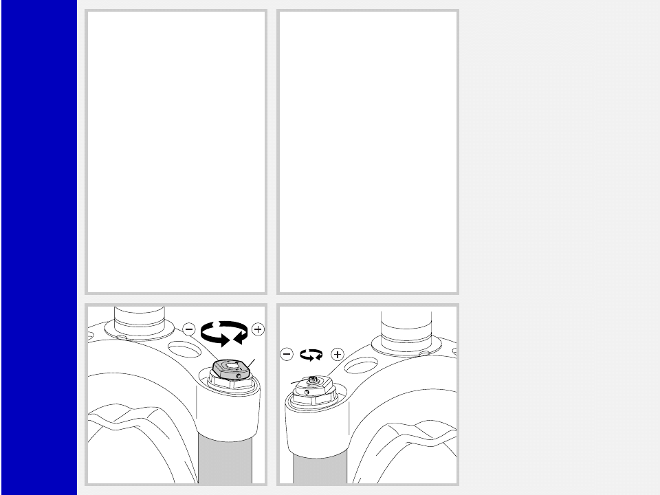
SPRING PRELOAD
The spring preload determines COMPRES-
SION damping and can be adjusted by
turning the knob (2) on top of the fork
legs. From the factory the fork is set at
minimum preload, i.e. the adjustment knob
completely unscrewed counterclockwise.
However, the springs are slightly
preloaded to help counteract static loads.
By turning the adjustment knob clockwise,
the preload is increased up to the maxi-
mum value equal to 15 mm’s of spring
preload. This adjustment is essential in
order to have the right fork response for
the rider’s weight and riding style.
REBOUND ADJUSTMENT
The right fork leg is equipped with an
adjuster screw (A) for REBOUND damp-
ing. Turning this adjuster clockwise into
the cartridge rod, changes the hydraulic
setting of the inner valves. In short, the
amount of adjustment applied on the pis-
ton in the fluid determines the rate of
damping.
To adjust, always start from the minimum
damping setting, i.e. unscrew completely
counterclockwise. About 8 turns - abt. 4
mm of the adjustment - are possible.
A
2

Z2
ATOM
Race
▲ ▲ ▲ ▲ ▲
▲ ▲ ▲ ▲ ▲
▲ ▲ ▲ ▲ ▲
▲ ▲ ▲ ▲ ▲
▲ ▲ ▲ ▲ ▲
▲ ▲ ▲ ▲ ▲
▲ ▲ ▲ ▲ ▲
▲ ▲ ▲ ▲ ▲
▲ ▲ ▲ ▲ ▲
▲ ▲ ▲ ▲ ▲
▲ ▲ ▲ ▲ ▲
▲ ▲ ▲ ▲ ▲
▲ ▲ ▲ ▲ ▲
▲ ▲ ▲ ▲ ▲
▲ ▲ ▲ ▲ ▲
▲ ▲ ▲ ▲ ▲
▲ ▲ ▲ ▲ ▲
▲ ▲ ▲ ▲ ▲
▲ ▲ ▲ ▲ ▲
DISASSEMBLY
GENERAL
– The reference numbers given in this section relate to the components shown in the forks exploded view.
– Before starting any operation, please read the diagram below. It shows the quickest procedure and the exact sequence in which
it should be disassembled. Locate the part you need to remove in the diagram, then look at the arrows to determine which other parts
you will need to remove first.
DISASSEMBLY DIAGRAM
FOOT NUT FIG. 6
PILOT BUSHING AND SEAL ASSEMBLY CHANGE
CARWON AND STANCHIONS ASSEMBLY
FIG. 9
SPRING CHANGE
PRELOAD KNOB FIG. 1
STANCHION TUBE CAP FIG. 3/4
SPRING FIG. 5
FORK OIL CHANGE
STOP RING FIG. 2
DUST SEAL FIG. 10
STOP RING FIG. 11
OIL SEAL FIG. 12
UPPER WASHER FIG. 13
PILOT BUSHING FIG. 14
PUMPING ROD AND REBOUND
SPRING FIG. 8
HYDRAULIC CARTRIDGE AND
REBOUND SPRING FIG. 7
PUMPING ROD CHANGE
(left leg)
HYDRAULIC CARTRIDGE CHANGE
(right leg)
Z2
ATOM
Race
2
3
4
5-15
6
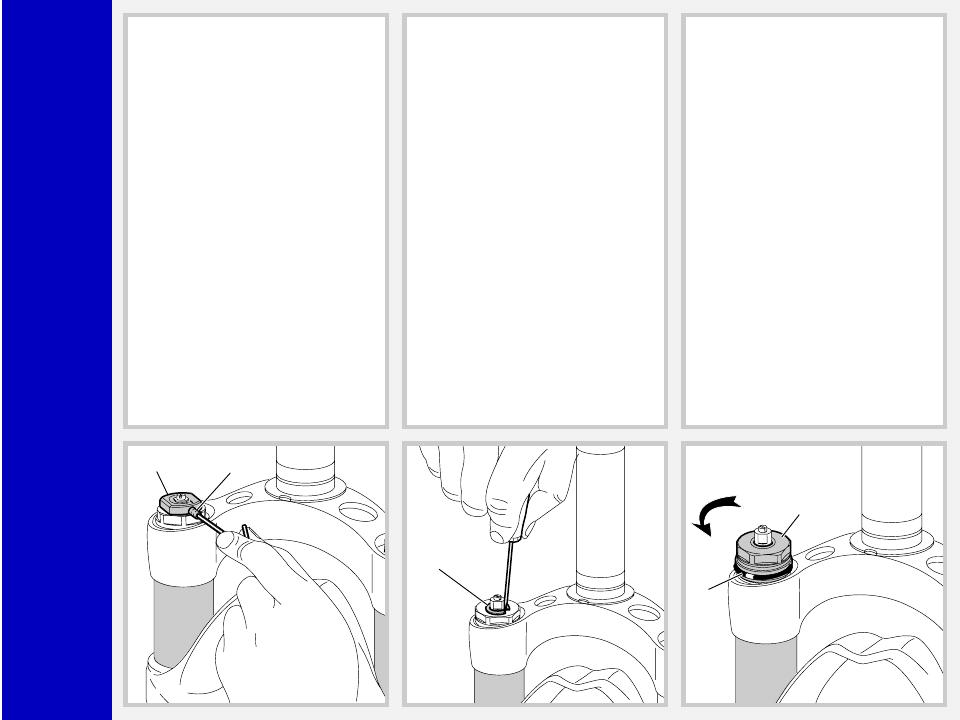
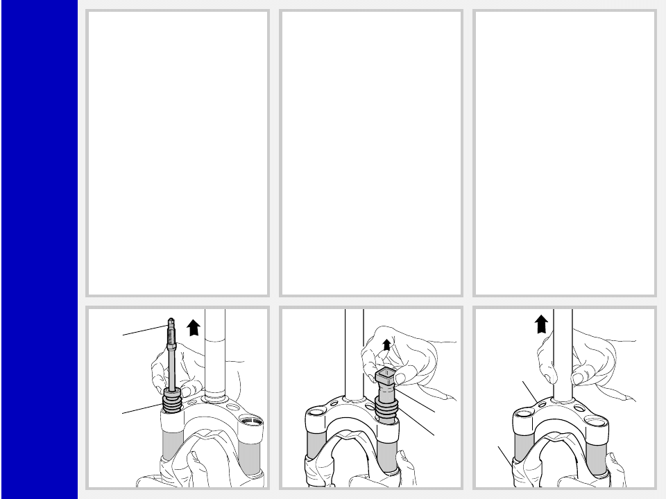
SPRING CHANGE
FIG. 1
Set knob (2) to minimum preload.
Loosen the small grub screw (3) fastening
the preload knob by means of a 1.5 mm
Allen wrench. Remove the knob from the
cap.
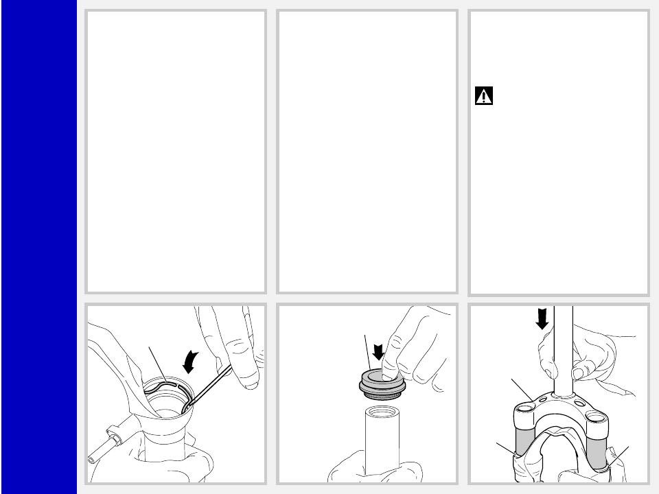
FIG. 2
Remove the stop ring (4) from the top of
the preload knob support with a small
screwdriver.
FIG. 3
Unscrew the caps (5) and (15) with a 21
mm socket wrench.
Remove the caps complete with O-ring (6)
from the stanchions.
Z2
ATOM
Race
15
12B
12
11
24
23
FIG. 4 (only right leg)
Lock the check nut (12B) and remove the
cap (15) from hydraulic cartridge end
(12).
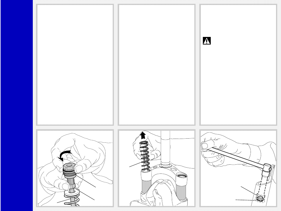
FIG. 5
Push the stanchions into the sliders and
remove the springs (11).
Let all the oil drain into the fork leg. By
following this procedure, there is no need
to check the oil level.
Make all necessary changes.
HYDRAULIC CARTRIDGE CHANGE
(right fork leg) AND PUMPING
ROD CHANGE (left fork leg)
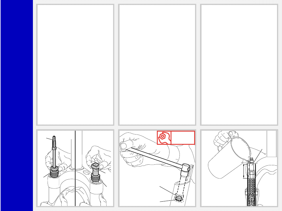
FIG. 6
Drain all oil from the fork legs.
WARNING: Remember to always
recycle any used oil.
To change the fork leg oil follow the
procedure as described in section
“REASSEMBLY” from Fig. 23 to Fig. 28.
Turn the fork leg upside-down and un-
screw the foot nut (24) complete with O-
ring (23) by the use of a 15 mm socket
wrench.
Z2
ATOM
Race
12
14
Dx.
13
14
Sx.
1
22
FIG. 7
Pull the hydraulic cartridge (12) complete
with rebound spring (14) and washer
(26, see exploded view) out of the R.H.
stanchion tube.
Replace the whole hydraulic cartridge.
FIG. 8
A pumping rod (13) complete with
rebound spring (14) and washer (26,
see exploded view) is fitted into the L.H.
leg, inside the stanchion. Withdraw the
above parts from the tube top by pushing
them from slider bottom.
PILOT BUSHING AND SEAL
ASSEMBLY CHANGE
FIG. 9
Pull the crown and stanchions assembly
(1) completely out of the sliders (22).
Z2
ATOM
Race
17
18
19
A
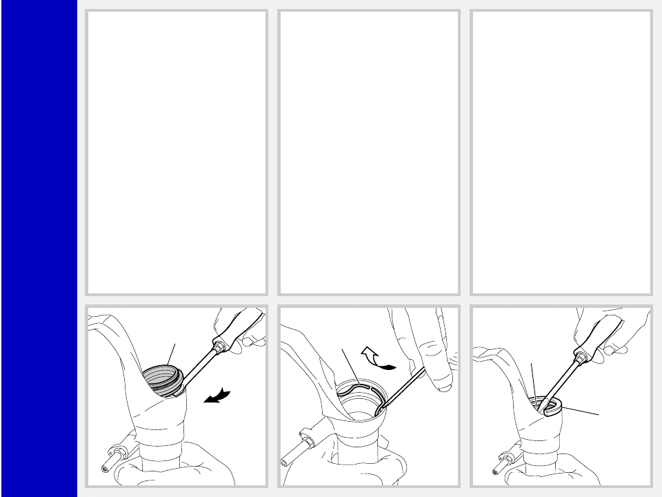
FIG. 10
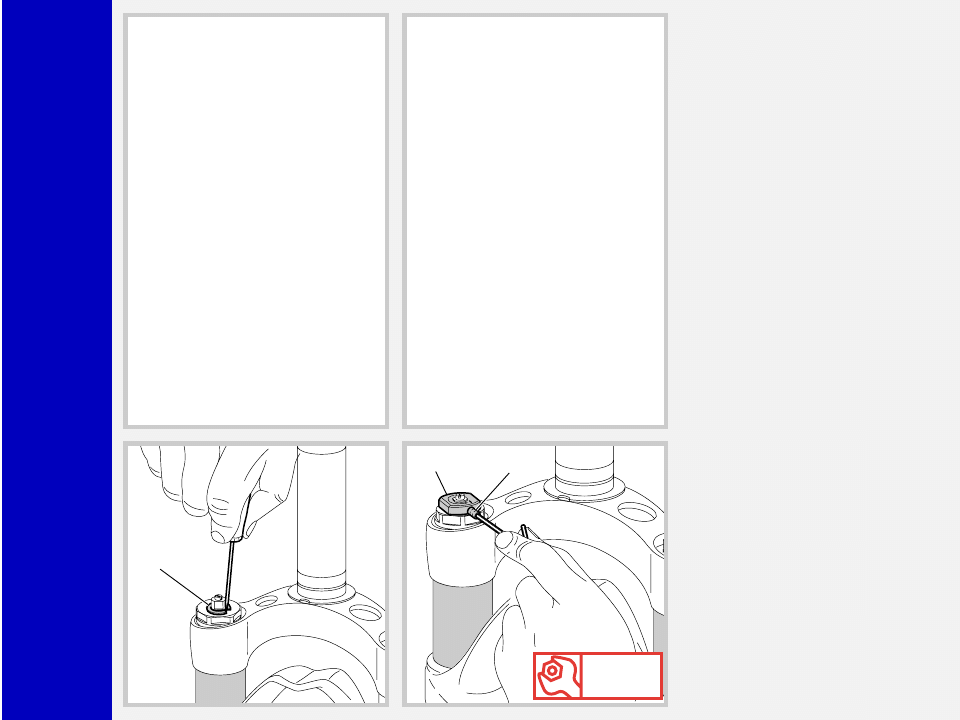
Use a small screwdriver and remove the
dust seal (17) from the top of the slider.
FIG. 11
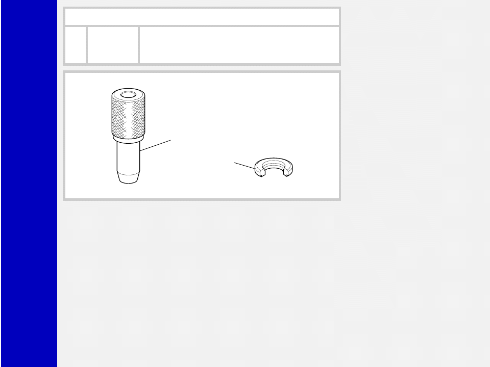
Remove the stop ring (18) from the slider
by placing the screwdriver bit in one of the
three openings on the stop ring and care-
fully lifting the ring out of place.
IMPORTANT: when removing the stop
ring, make sure not to damage its seat.
FIG. 12
Fit the slider protector (A) onto the slider
and remove the oil seal (19) with the help
of a large slot screwdriver.
IMPORTANT: when removing the oil
seal, make sure not to damage its seat.
Once removed the oil seals should not be
used again.
Z2
ATOM
Race
20
21
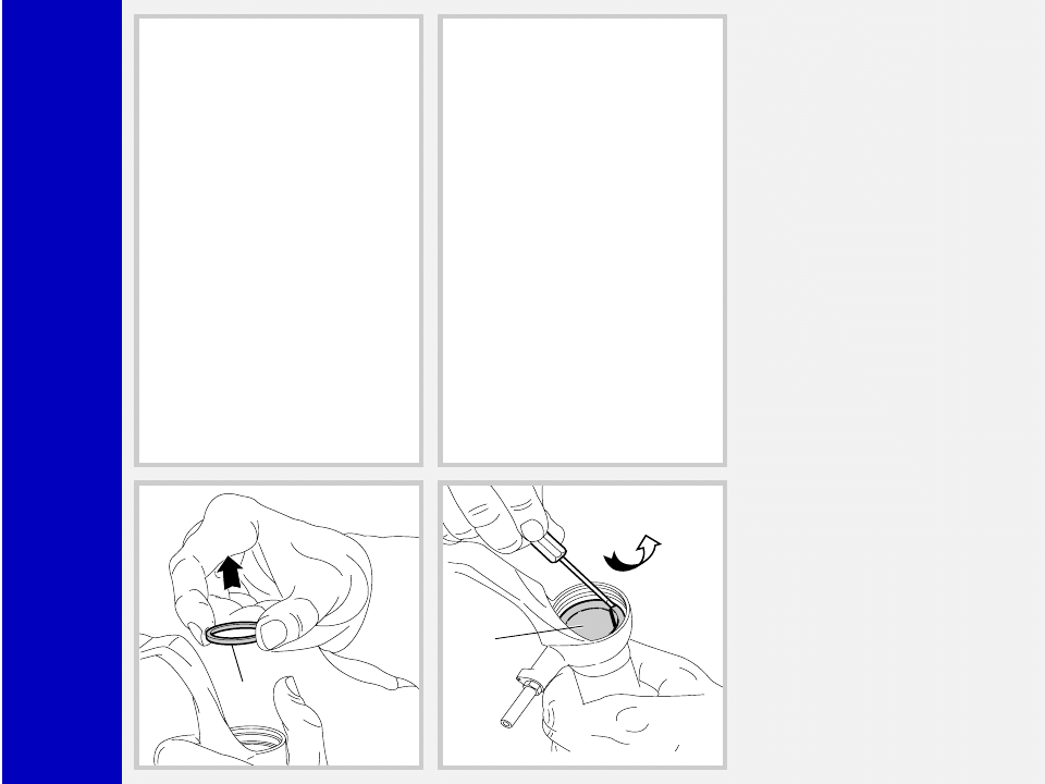
FIG. 13
Remove the upper washer (20) from the
slider.
FIG. 14
Fit the bit of a small screwdriver into the
upper edge slot of the pilot bushing (21)
and lift gently. Pull the bushing out of the
slider and make all necessary changes.
Z2
ATOM
Race
21
20
19
B
REASSEMBLY
CAUTION: before reassembling, clean
all metal parts carefully with inflammable
and biodegradable solvent and dry them
with compressed air.
PILOT BUSHING AND SEAL
ASSEMBLY
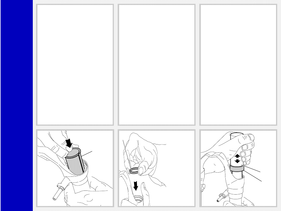
FIG. 15
Check that no dirt or debris is between
slider and bushing. Insert the pilot bushing
(21) into place so that it adheres to the
slider.
FIG. 16
Fit the upper washer (20) into the slider so
that it touches the pilot bushing.
FIG. 17
Lubricate the oil seal (19) and place it
onto the seal press (B) with the hollow
side toward the slider.
Press the oil seal into place until it touches
the lower washer by using the above seal
press.
Z2
ATOM
Race
18
17
1
17
17
FIG. 18
Insert the stop ring (18) making sure it is
properly seated into place.
Use buffer (B) to properly seat the ring
into the slider.
FIG. 19
Lubricate the dust seals (17) and fit them
into the stanchions from the spring end.
CROWN AND STANCHIONS
ASSEMBLY
FIG. 20
Fit the stanchions (1) and crown assembly
with the dust seals in place gently into the
sliders seals.
WARNING: to avoid any dam-
ages to sealing surfaces, keep the
stanchions duly lubricated and squared
into the sliders.
Press the crown and stanchions assembly
fully down and check that threaded ends of
cartridge (12) and pumping rod (13) are
coming out through the bottom of the sliders.
Check to see that the stanchion tube slides
unrestricted by cycling the fork up and
down several times.
The tube should slide freely inside the seal
assembly without any side play.
In the event it is too hard or too soft, repeat
the previous steps described above and
check components to ensure they are not
damaged.
Seat the dust seals (17) on top of the
sliders.
Z2
ATOM
Race
12
14
14
13
Dx.
Sx.
24
23
Nm
12
30
12
HYDRAULIC CARTRIDGE (right leg)
AND PUMPING ROD (left leg)
FIG. 21
Push the stanchions up to slider bottom.
Insert hydraulic cartridge (12), complete
with rebound spring (14) and washer
(26) in the RH stanchion tube.
Insert pumping rod (13), with rebound
spring (14) and washer (26) fitted on it,
in LH stanchion tube.
Push complete hydraulic cartridge (12)
and pumping rod (13) into stanchion
bottom.
FIG. 22
Grease the O-ring (23) on the foot nut
(24) and screw the nut on the threaded
end of both the hydraulic cartridge and
the pumping rod.
Tighten to 12 Nm.
Check to verify that the stanchions slide
properly through the stroke by pumping
them up and down several times.
HOW TO FILL WITH OIL
FIG. 23
Pour the oil little by little when the stan-
chions are fully down and then pump with
the cartridge (12) rod so as to have a
better filling. Cartridge is full when no air
is detected when pumping, in the com-
pletely closed position. Check that oil
level is 30 mm from the top of the stan-
chion tube in both fork legs.
Z2
ATOM
Race
11
Dx.
15
6
12
10
Nm
12
5-15
SPRING AND CAP
FIG. 24
Fit the spring (11) into the stanchions.
Move the preload adjuster (9, see ex-
ploded view), in the cap, to the minimum
preload position.
FIG. 25 (right leg only)
Lubricate the O-ring (7, see exploded
view) on the top of the preload knob
support (right leg only) and the O-ring (6)
on the caps (5) and (15).
Screw the cap (15) complete with preload
adjuster (9) and lower washer (10) onto
the cartridge (12) rod. Screw cap all the
way in.
Tighten check nut (12B) against cap
(15).
FIG. 26
Lift the stanchions and start the caps (5)
and (15) onto the threads by hand.
Tighten the caps to 12 Nm.
Z2
ATOM
Race
4
2
3
Nm
1,5
FIG. 27
Fit the stop ring (4) of the preload knob
support and make sure it is properly
seated into place.
FIG. 28
Fit the preload knob (2) and secure it on
the support by tightening the grub screw
(3) to 1.5 Nm.
Z2
ATOM
Race
SPECIFIC TOOLS
R e f .
I t e m .
Description and use
A
R 5089 AB
Slider protector: to remove the oil seal from the slider
B
R 5090
Oil seal press: to press oil seal into the slider
A
B
Wyszukiwarka
Podobne podstrony:
2000 z2 atom bomb 80
Thomas C Holt The Problem of Race in the Twenty first Century (2001)
W 5 ATOM
PiU P Z2
2001 08 28
bph pbk raport roczny 2001
2001 11 29
zegarmistrz 731[05] z2 02 u
711[04] Z2 04 Wykonywanie konse Nieznany (2)
mechanik operator pojazdow i maszyn rolniczych 723[03] z2 04 n
arkusz fizyka poziom s rok 2001 535
2001 październik Cztery pory roku kryteria
fototechnik 313[01] z2 04 n
2001 06 30
monter instalacji gazowych 713[07] z2 03 u
operator urzadzen przemyslu szklarskiego 813[02] z2 07 n
Porty morskie i żegluga morska w Polsce w latach 1999 2001
operator urzadzen przemyslu spozywczego 827[01] z2 02 u
121 307 POL ED02 2001
więcej podobnych podstron