
Initial Print Date: 08/03
Revision Date: 09/03
Subject
Page
E60 Engines
Objectives . . . . . . . . . . . . . . . . . . . . . . . . . . . . . . . . . . . . . . . . . . . . . . . ..2
M54 Engine
Purpose of the System . . . . . . . . . . . . . . . . . . . . . . . . . . . . . . . . . . . . . .3
Technical Data . . . . . . . . . . . . . . . . . . . . . . . . . . . . . . . . . . . . . . . . . . . . .3
System Components . . . . . . . . . . . . . . . . . . . . . . . . . . . . . . . . . . . . . . . .4
Electric Fan - Removal . . . . . . . . . . . . . . . . . . . . . . . . . . . . . . . . . . . . . . .8
N62 Engine
Purpose of the System . . . . . . . . . . . . . . . . . . . . . . . . . . . . . . . . . . . . . .9
Technical Data . . . . . . . . . . . . . . . . . . . . . . . . . . . . . . . . . . . . . . . . . . . .10
System Components . . . . . . . . . . . . . . . . . . . . . . . . . . . . . . . . . . . . . . .11
Valvetronic - Overview . . . . . . . . . . . . . . . . . . . . . . . . . . . . . . . . . . . . . .12
Table of Contents
E60 Engines

2
E60 Engines
E60 Engines
Model: E60 - 525i, 530i, 545i
Engines: M54B25, M54B30, N62B44
Production: Start of Production MY 2004
Objectives:
After completion of this module you will be able to:
• Identify the changes on the M54 Engine as applied to the E60.
• Remove and install the Electric fan.
• Familiarize yourself with the N62B44 from the E65.
3
E60 Engines
M54 Engine
Purpose of the System
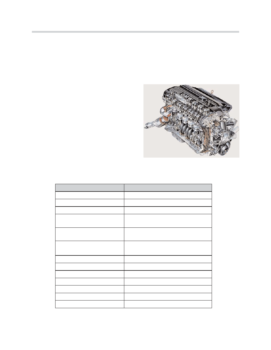
The E60 530i is equipped with the M54 engine. The M54 engine is adapted for use in the
E60 and the changes include:
• Engine peripherals:
- Fresh air system Cooling system
- Exhaust system
- Ancillary components and belt drive
- Cooling module (without viscous fan)
• MS45.1 Engine Management System
• Fuel system
Technical Data
KT-10146
Engine
M54B25 / M54B30
Configuration
6-cylinder in-line
Displacement (cc)
2494 / 2979
Bore / stroke (mm)
84 x 75 / 84 x 89.6
Power output (bhp)
at engine speed (rpm)
184 / 225
6000 / 5900
Torque (ft lb)
at engine speed (rpm)
175 / 214
3500
Idle speed (rpm)
Max. engine speed (rpm)
640
6500
Compression ratio (:1)
10.5 / 10.2
Valves per cylinder
4
Fuel requirement
Premium unleaded
Knock control
yes
Engine management system
Siemens MS45.1 (US)
Emission compliance
ULEV II (US)
Firing order
1-5-3-6-2-4
4
E60 Engines
System Components
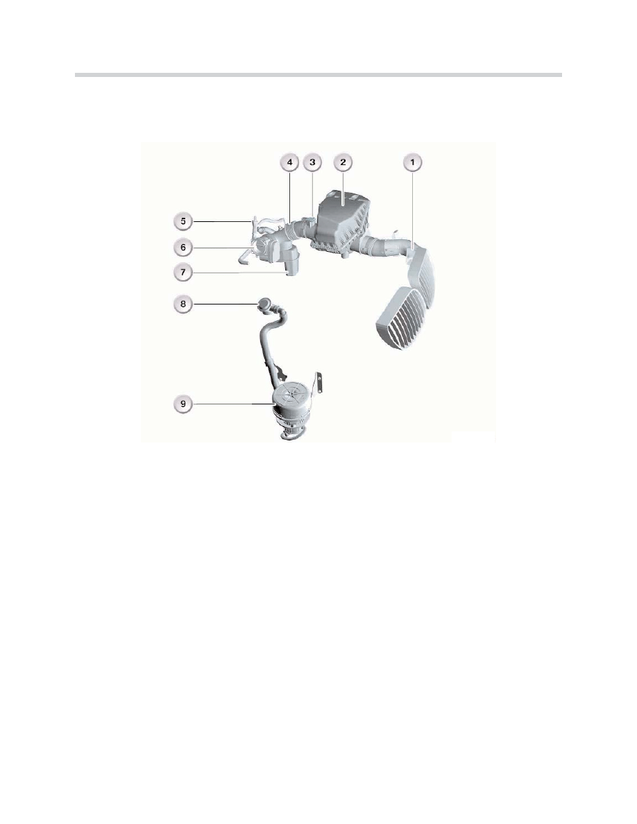
Fresh Air System
1. Intake snorkel 6. Electronic throttle (EDK)
2. Air filter housing
7. Intake noise resonator
3. Hot film air mass sensor (HFM) 8. Secondary air valve
4. Intake air boot 9. Secondary air pump
5. Suction-jet pump
Hot Film Air Mass Sensor (HFM)
The HFM is a compact plug in design, it is mounted directly into the clean air outlet of the
air filter housing. This design eliminates the grille in front of the HFM. This reduces flow
resistance in the air intake ducting, resulting in lower fuel consumption.
Air Filter
The intake air filter housing has a volume of approximately 13 litres.
KT-11147
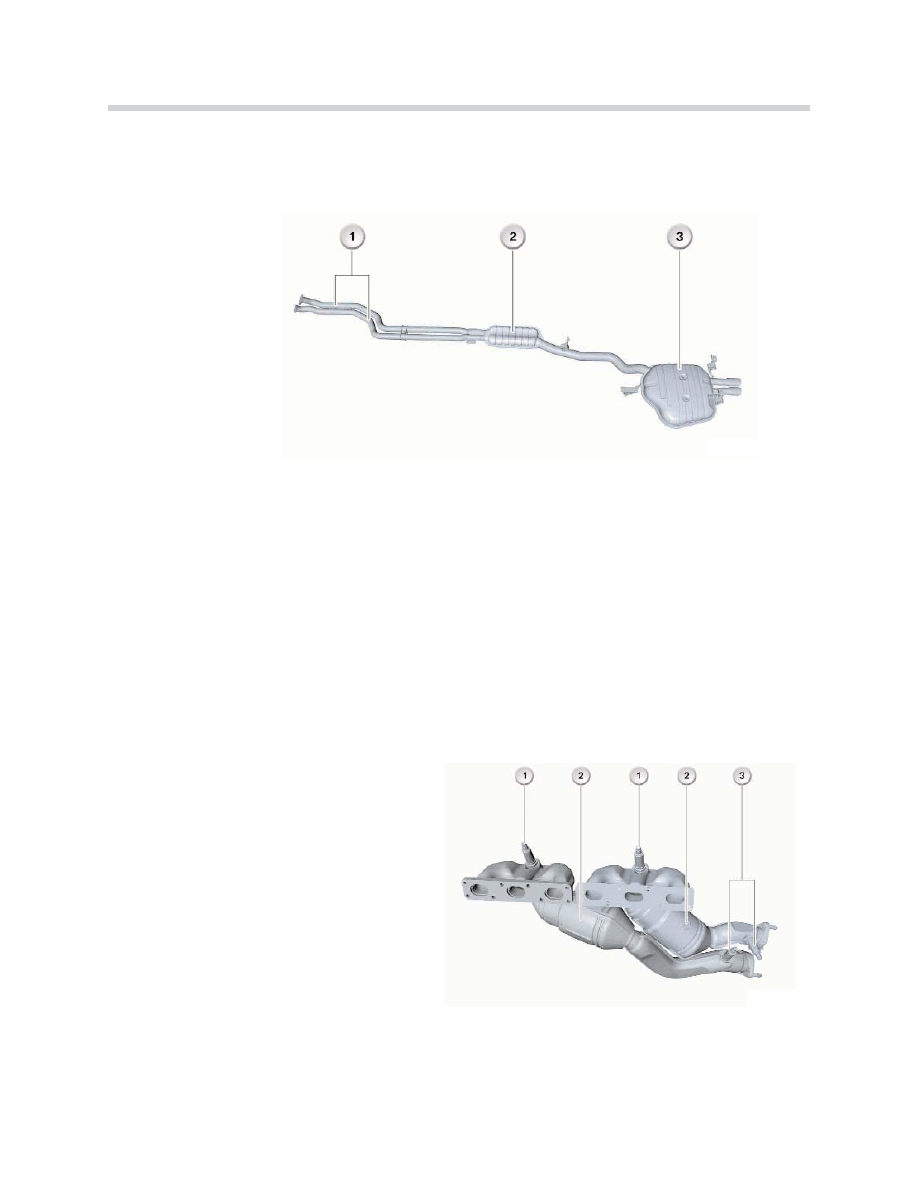
Exhaust System
The E60 exhaust system has been specifically developed for the M54 engine.
1. Front pipe
2. Middle silencer
3. Rear silencer
S
Siille
en
nc
ce
err
The exhaust system is made of stainless steel and is designed as a single unit up to the
exhaust manifolds. The exhaust system consists of a middle silencer with a volume of 4.8
litres and a rear silencer with a volume of 26.2 litres.
N
No
otte
e:: Regarding service repairs, the middle and rear silencers can be ordered and replaced
separately.
V
Va
arriia
an
ntts
s
The shape of the stainless steel exhaust system is the same up to the exhaust manifolds
for all engine (M54) and transmission variants.
E
Ex
xh
ha
au
us
stt M
Ma
an
niiffo
olld
ds
s
The exhaust manifolds with upstream
catalytic converters have been used in
previous M54 applications.
1. Oxygen sensors (pre-catalyst)
2. Catalytic converters
3. Catalyst Monitoring (post) oxygen sensors
V
Va
arriia
an
ntts
s
Depending on the exhaust emissions leg-
islation, the exhaust manifolds have different catalyst coatings (world wide).
5
E60 Engines
KT-11147
KT-11152
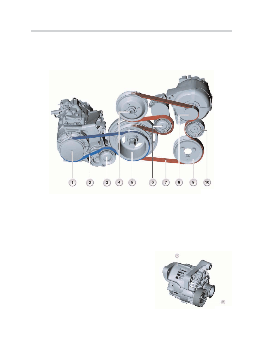
Ancillary Components and Belt Drive
M
Mo
od
diiffiic
ca
attiio
on
ns
s
The alternator is fitted with a deflection pulley. The width of the ribbed V-belt for the A/C
compressor drive has been reduced from 5 to 4 ribs.
1. A/C compressor 6. Tensioning pulley
2. Ribbed V-belt, A/C compressor drive 7. Ribbed V-belt, main drive
3. Tensioning pulley 8. Alternator
4. Belt pulley, water pump
9. Belt pulley, power-steering pump
5. Vibration damper 10. Deflection pulley
A
Alltte
errn
na
atto
orr
A Bosch alternator (1) with a charging current of 140 A
is used on the M54. Due to the high alternator output,
the alternator is fitted with a deflection pulley (2) for the
ribbed V-belt.
The deflection pulley is a component part of the alter-
nator and ensures that the ribbed V-belt is looped to
better effect round the alternator pulley. Refer to the
ST045 E85 Training Handout for alternator control.
6
E60 Engines
KT-11154
KT-11155
Cooling System
Only the modifications to the cooling system of the M54 for use in the E60 are addressed.
The cooling module is similar in design to the E65. The transmission oil cooler for the auto-
matic transmission is identical to that of the E65. A
An
n e
en
ng
giin
ne
e o
oiill c
co
oo
olle
err a
an
nd
d v
viis
sc
co
ou
us
s ffa
an
n a
arre
e
n
no
ott u
us
se
ed
d iin
n tth
he
e E
E6
60
0 w
wiitth
h M
M5
54
4 e
en
ng
giin
ne
e.. No modifications have been made to the cooling
system on the engine side.
N
Ne
ew
w F
Fe
ea
attu
urre
es
s
• Coolant expansion tank with facility for draining off leakage at the expansion tank cap.
• Lifetime coolant, routine flushing is not required.
The electric fan is mounted on the fan cowl and acts by drawing air through the radiator.
The speed is variably regulated by the ECM.
N
No
otte
e:: Automatic transmission equipped E60’s with M54 have a 600 W fan.
The coolant expansion tank is located outside the cooling module on the right hand strut
tower. The tank is made of black plastic and incorporates a float rod with min. and max.
markings to determine the coolant level. A float with a reed contact is located in the base
of the tank for the low level warning.
The cap on the expansion tank limits the pressure in the cooling system. The cap incor-
porates two valves. The pressure relief valve opens from a cooling system pressure of 2
bar. The vacuum valve opens in the event of a small vacuum pressure in the cooling
system.
7
E60 Engines
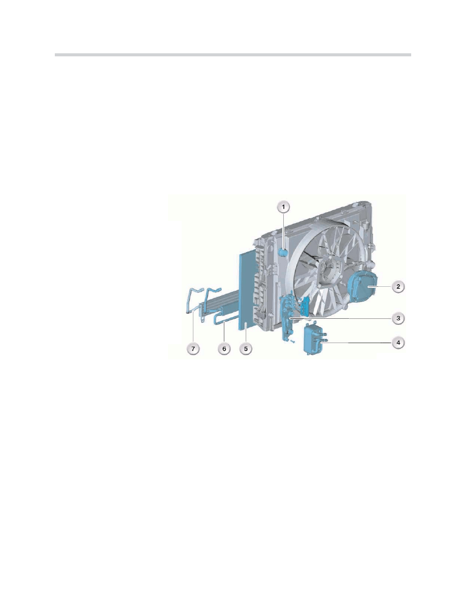
KT-11157
1. Coolant connection (upper radiator
hose)
2. Electric fan motor
3. Mounting plate with thermostat
(transmission-oil cooler)
4. Transmission oil cooler
5. A/C condenser
6. Power steering cooler
7. Cooler for active steering (AFS)
N
No
otte
e:: The opening pressures of the cap for the coolant expansion tank differ depending on
the type of engine used. The caps for the coolant expansion tank are engine specific and
must not be mixed up. The value of the opening pressure is cast into the inside of the cap
and can be read off there (e.g. 200 = 2 bar opening pressure).
When the cap opens at a system pressure of 2 bar, it allows pressure to escape and with
it coolant from the side. In the previous model series, the coolant left behind contaminants
on the expansion tank.
The coolant expansion tank of the E60 is pro-
vided with a drain edge all round the cap. This
drain edge serves to catch the escaping
coolant.
Inside the drain edge is a drain channel which
passes through the expansion tank. The
escaping coolant is routed through this drain
channel to the right-hand wheel-arch trim,
where it evaporates.
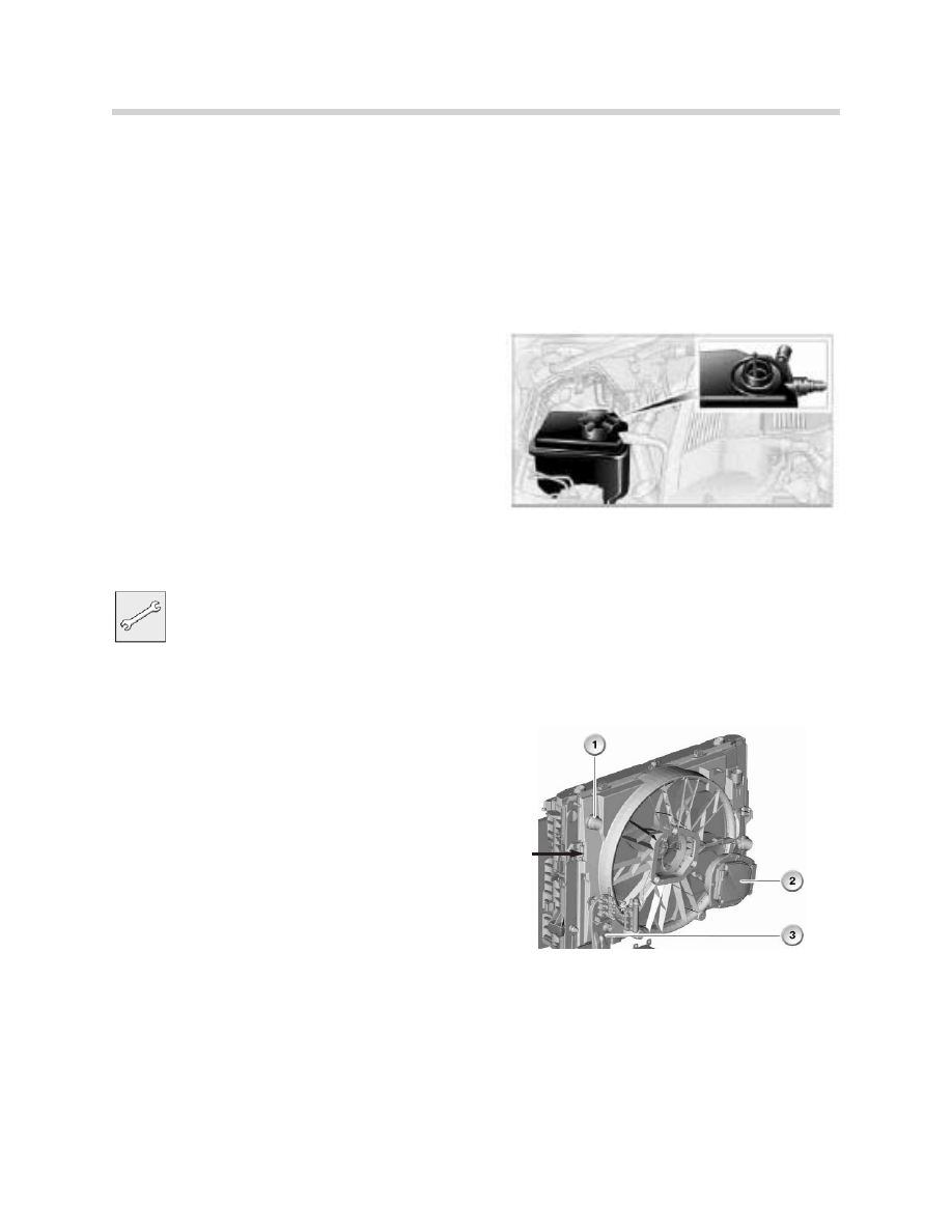
Workshop Exercise - Electric Fan Removal
The electric fan can be removed without removing the coolant connection (1) and the
mounting plate with thermostat (3).
W
Wiitth
h IIn
ns
sttrru
uc
ctto
orr’’s
s a
as
ss
siis
stta
an
nc
ce
e,, rre
em
mo
ov
ve
e tth
he
e e
elle
ec
cttrriic
c
ffa
an
n..
1
1.. R
Re
em
mo
ov
ve
e tth
he
e tto
op
p c
co
on
nn
ne
ec
cttiin
ng
g p
plla
atte
e ((c
co
om
mp
plle
ette
e
v
ve
eh
hiic
clle
e s
se
ec
cttiio
on
n)) a
an
nd
d rra
ad
diia
atto
orr tto
op
p c
co
ov
ve
err..
2
2.. L
Liifftt tth
he
e ffa
an
n ((s
slliig
gh
httlly
y)) o
ou
utt o
off tth
he
e ““U
U”” s
sh
ha
ap
pe
ed
d
rre
etta
aiin
niin
ng
g b
brra
ac
ck
ke
etts
s ((lle
efftt a
an
nd
d rriig
gh
htt)) a
an
nd
d ffo
olld
d iin
n
tth
he
e ““h
hiin
ng
ge
ed
d”” tta
ab
b ((lle
efftt s
siid
de
e -- a
arrrro
ow
w)) tto
o g
ga
aiin
n
c
clle
ea
arra
an
nc
ce
e..
3
3.. T
Th
he
en
n tth
he
e e
elle
ec
cttrriic
c ffa
an
n c
ca
an
n b
be
e rre
em
mo
ov
ve
ed
d tth
he
e rre
es
stt
o
off tth
he
e w
wa
ay
y.. T
Th
he
e e
elle
ec
cttrriic
c ffa
an
n m
mo
otto
orr ((2
2)) rre
em
ma
aiin
ns
s
iin
n p
plla
ac
ce
e u
un
nttiill tth
he
e ffa
an
n a
as
ss
se
em
mb
blly
y iis
s rre
em
mo
ov
ve
ed
d
ffrro
om
m v
ve
eh
hiic
clle
e..
N
No
otte
e:: When installing electric fan, remember to unfold the “hinged” tab before fitting into
“U” shaped brackets.
8
E60 Engines
KT-061603
KT-11157 B
9
E60 Engines
N62 Engine
Purpose of The System
The E60 545i is equipped with the N62B44 (NG - New Generation) engine used in the E65.
Please refer to ST042 E65 Complete Vehicle Part 2 for additional details and information.
The development objectives were:
• Reduction in fuel consumption
• Reduction in emissions
• Increased power
• Improved torque and torque curve
• Improved engine acoustics
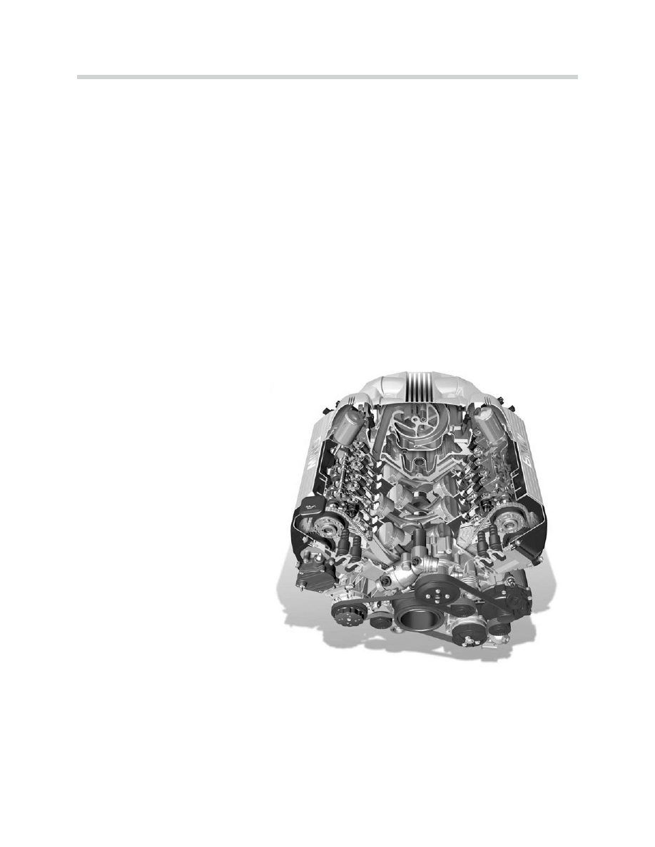
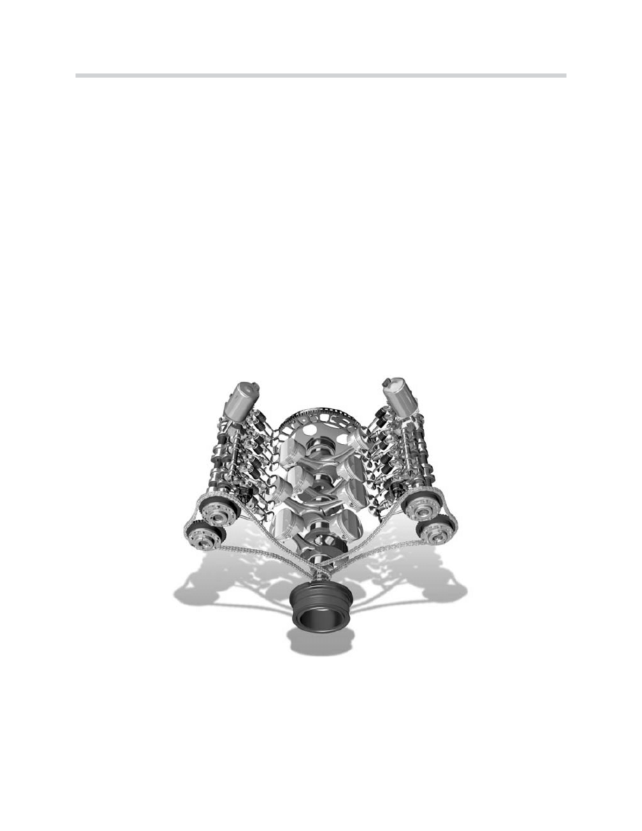
The most important features of the
new N62 engine are:
• 8 cylinders in a 90º V configu-
ration
• 2 four-valve cylinder heads
• Light-alloy design
• Newly-developed variable
intake manifold
• Valvetronic system
In conjunction with the Variable Intake Manifold, the Valvetronic system adapts the intake
valve lift to ensure optimum cylinder filling. The throttle valve use is limited during engine
operation to maintain a constant intake manifold vacuum.
To achieve these objectives, enhancements
were made in the following areas:
• Engine mechanicals
• Treatment of exhaust emissions
• Valve timing
• Engine management control
• Intake air flow
• Electric fan only (no viscous fan)
43-02-01

10
E60 Engines
Technical Data
E
En
ng
giin
ne
e
N
N6
62
2B
B4
44
4
Design
8 Cylinder V
V Angle
90°
Displacement (cm3)
4,398
Bore/Stroke (mm)
92/82.7
Cylinder Gap (mm)
98
Main Crankshaft Bearing Diameter (mm)
70
Output (HP)
at speed (rpm)
325
6,100
Torque (FT.LBS)
at Speed (RPM)
330
3,600
Cut-off speed (RPM)
6.500
Compression Ratio
10.0
Valves / Cylinders
4
Intake Valve Diameter (mm)
35
Exhaust Valve Diameter (mm)
29
Intake Valve Lift (mm)
0.3 – 9.85
Exhaust Valve Lift (mm)
9.7
Cams Open Period (º crankshaft)
282/254
Engine Weight (kg)
213
Fuel
91 Octane
Firing Order
1-5-4-8-6-3-7-2
Knock Sensor
Yes
Variable Intake Manifold
Yes
Digital Motor Electronics
ME 9.2 with Valvetronic Control Unit
Complies with Exhaust Emission Regulations
EU-3
EU-4
LEV
Engine Length (mm)
704
Fuel Consumption Saving Compared with the M62
14%
(US)
Premium unleaded
5,900
11
E60 Engines
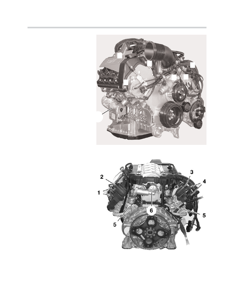
System Components
1
2
3
4
5
6
7
42-02-03
N62B44 Engine (Front View)
1. Starter Motor
2. Valvetronic Motor
3. Evaporative Emission Valve
4. VANOS Solenoid Valve
5. Thermostat Housing
6. Throttle Unit
7. Vacuum Pump
N62B44 Engine (Rear View)
1. Camshaft Position Sensor Cylinder
Bank 5-8
2. Valvetronic Eccentric Shaft Position
Sensor, Cylinder Bank 5-8
3. Valvetronic Eccentric Shaft Position
Sensor, Cylinder Bank 1-4
4. Camshaft Position Sensor Cylinder
Bank 1-4
5. Secondary Air Non-return Valves
6. Servomotor for Variable Intake
Manifold
42-02-04
12
E60 Engines
Valvetronic
Over the entire speed and load range, the gasoline engine needs a combustible fuel-air
mixture within the ideal ratio (Lambda = 1). The mixture quantity must be altered to vary
the speed and output. This variation is effected by the throttle valve. The mixture, which
falls within the narrow range of Lambda = 1, is formed outside the combustion chamber
using the fuel injection system (external mixture formation).
The mixture control is influenced by the throttle valve and is not optimal in all the different
load ranges. This is particularly true in the idle to part-load ranges, since the throttle valve
is only opened slightly in these ranges. The consequences are less than optimal cylinder
filling, torque and increased fuel consumption.
Technical measures were previously introduced; such as the optimization of air/fuel mixing,
improved valve overlap, introduction of DISA and the steady improvement of mixture con-
trol all depend on the throttle valve. This is where the completely unique Valvetronic design
comes in.
The Valvetronic system simultaneously varies the valve opening time and the valve opening
lift between 0.3 mm and 9.85 mm, according to engine speed and load. This means that
the air/fuel mixture volume is controlled according to engine requirements. This type of
mixture and volume control makes the typical throttle valve control unnecessary.
43-02-27
Document Outline
- Main Menu
- E60 Complete Vehicle
- E60 Engines
- E60 Engine Management
- E60 Driveline
- E60 Chassis Dynamics
- E60 Active Front Steering
- E60 Dynamic Drive
- E60 Climate Control
- E60 Advanced Safety Electronics
- E60 Voltage Supply and Bus Systems
- E60 General Vehicle Electrical Systems
- E60 Driver Information
- E60 Communication Systems
Wyszukiwarka
Podobne podstrony:
02 2007 Engine Technology
02 engine electrical system
Engineering Symbols, Prints and Drawings 02 US DOE
02 Engine Diagnosis
Wyk 02 Pneumatyczne elementy
02 OperowanieDanymiid 3913 ppt
02 Boża radość Ne MSZA ŚWIĘTAid 3583 ppt
OC 02
PD W1 Wprowadzenie do PD(2010 10 02) 1 1
02 Pojęcie i podziały prawaid 3482 ppt
WYKŁAD 02 SterowCyfrowe
02 filtracja
02 poniedziałek
21 02 2014 Wykład 1 Sala
więcej podobnych podstron