
G
B
D
F
I
N
L
E
P
G
R
R
U
T
R
Air-Conditioners For Building Application
INDOOR UNIT
PEFY-P-VML-A
INSTALLATION MANUAL
For safe and correct use, please read this installation manual thoroughly before installing the air-conditioner unit.
INSTALLATIONSHANDBUCH
Zum sicheren und ordnungsgemäßen Gebrauch der Klimageräte das Installationshandbuch gründlich durchlesen.
MANUEL D’INSTALLATION
Veuillez lire le manuel d’installation en entier avant d’installer ce climatiseur pour éviter tout accident et vous assurer d’une utilisation correcte.
MANUAL DE INSTALACIÓN
Para un uso seguro y correcto, lea detalladamente este manual de instalación antes de montar la unidad de aire acondicionado.
MANUALE DI INSTALLAZIONE
Per un uso sicuro e corretto, leggere attentamente questo manuale di installazione prima di installare il condizionatore d’aria.
INSTALLATIEHANDLEIDING
Voor een veilig en juist gebruik moet u deze installatiehandleiding grondig doorlezen voordat u de airconditioner installeert.
MANUAL DE INSTALAÇÃO
Para segurança e utilização correctas, leia atentamente este manual de instalação antes de instalar a unidade de ar condicionado.
E°XEIPI¢IO O¢H°IøN E°KATA™TA™H™
°È· ·ÛÊ¿ÏÂÈ· Î·È ÛˆÛÙ‹ ¯Ú‹ÛË, ·Ú·Î·Ï›ÛÙ ‰È·‚¿ÛÂÙ ÚÔÛ¯ÙÈο ·˘Ùfi ÙÔ ÂÁ¯ÂÈÚ›‰ÈÔ ÂÁηٿÛÙ·Û˘ ÚÈÓ ·Ú¯›ÛÂÙ ÙËÓ
ÂÁηٿÛÙ·ÛË Ù˘ ÌÔÓ¿‰·˜ ÎÏÈÌ·ÙÈÛÌÔ‡.
РУКОВОДСТВО ПО УСТАНОВКЕ
Для осторожного и правильного использования прибора необходимо тщательно ознакомиться с данным руководством по
установке до выполнения установки кондиционера.
MONTAJ ELK‹TABI
Emniyetli ve do¤ru biçimde nas›l kullan›laca¤›n› ö¤renmek için lütfen klima cihaz›n› monte etmeden önce bu elkitab›n› dikkatle okuyunuz.
3
3.2
[Fig. 3.2.1]
B
C
F
D
A
3
4
E
A
50~150
450
450
50~150
8
55
459
545(*1)
40
664
690
23
23
10
225(*2)
14
664
1
2
A
Access door
B
Electrical parts box
C
Air inlet
D
Air outlet
E
Ceiling surface
F
Service space
* If the optional long-life filter is installed, the dimensions of the air
conditioner increase.
Rear inlet:
Depth increases by 30 mm (*1)
Bottom inlet: Height increases by 30 mm (*2)
A
B
D
C
E
E
A
Ceiling board
B
Edge beam
C
Tie beam
D
Square timber for hanging the air
conditioner
E
Pitch
F
G
H
F
Insert: 100 to 150 kg (1
piece) (field supply)
G
M10 hanging bolt (field
supply)
H
Reinforcement
4
4.1
[Fig. 4.1.1]
197
142
57
178
43
A B
C
A
Refrigerant pipe (liquid pipe): HP
B
Refrigerant pipe (gas pipe): LP
C
Drain pipe
A
B
A
B
A
Filter
B
Bottom plate
A
Filter
B
Bottom plate
B
A
A
C
D
C
E
D
A
Unit body
B
Lifting machine
C
Nuts (field supply)
D
Washers (field supply)
E
M10 hanging bolt (field supply)
[Fig. 4.1.2]
5
[Fig. 5.0.1]
[Fig. 5.0.2]
6
6.2
[Fig. 6.1.1]
[Fig. 6.1.2]
[Fig. 6.2.1]
6.1
7
7.2
[Fig. 7.2.1]
1
500 or more
2
100 or more
3
20 or more
4
300 or more
2
3
A
Cut here
B
Remove brazed cap
A
A
E
C
F
B
D
A
Thermal insulation
B
Pull out insulation
C
Wrap with damp cloth
D
Return to original position
E
Ensure that there is no gap here
F
Wrap with insulating tape
C
C
C
D
2
E
A
B
1
A
Downward slope 1/100 or more
B
Connection dia. R1 external thread
C
Indoor unit
D
Collective piping
E
Maximize this length to approx. 10 cm
G
F
H
E
D
C
B
A
A
Air inlet
B
Air outlet
C
Access door
D
Ceiling surface
E
Canvas duct
F
Connect common reference potential wire between
duct-work to air conditioner.
G
Air filter
H
Inlet grille
A
B
D
E
C
C
C
C
C
C
C
A
Switch 16 A
B
Overcurrent protection 16 A
C
Indoor unit
D
Total operating current be less than 16 A
E
Pull box
8
8.2
[Fig. 8.1.1]
[Fig. 8.2.1]
8.1
[Fig. 8.1.2]
9
[Fig. 9.0.1]
10
10.1
[Fig. 10.1.1]
[Fig. 10.2.1]
10.2
A
A
C
TB5
TB5
S
M1M2
S
M1M2
C
B
TB3
M1M2
A
A
C
TB5
TB15 TB5
TB15
S
M1M2
S
M1M2
B
TB3
M1M2
2
1
C
2
1
A
Terminal block for indoor
transmission cable
B
Terminal block for outdoor
transmission cable
C
Remote controller
[Fig. 10.2.2]
M2
DC24~30V
M1
(A, B)
1
2
D
A
C
L
N
DC10~13V
A
B
1
2
L
N
1
2
A
C
B
A
Non-polarized
B
Upper level (TB15)
C
Remote Controller
D
Lower level (TB5)
[Fig. 10.2.3]
[Fig. 10.2.4]
4
E
F
G
I
H
M2
M1
N
L
K
J
L
M
N
O
M2
S
M1
A
B
C
F
E
D
A
C
B
E
To prevent external tensile force from applying to the wiring connection section of
power source terminal bed use buffer bushing like PG connection or the like.
F
Power source wiring
G
Tensile force
H
Use ordinary bushing
I
Transmission wiring
J
Power source terminal bed
K
Terminal bed for indoor transmission
L
To 1-phase power source
M
Transmission line DC 30 V
N
Terminal bed for outdoor transmission line (TB3)
O
Transmission line to the remote controller, terminal bed for indoor unit and
BC controller
A
Terminal bed
B
Round terminal
C
Shield wire
D
Two shield wires may be connected together at the shield relay terminal bed
E
One shield wire is connected with another shield wire. (Terminal connection)
F
Insulation tape (for the earthing of shield and the prevention of contact to transmission terminal)
A
Terminal bed box connector (White)
B
Motor connector (White)
C
Attachment connector (Blue) (Accessory)
CN62
SW1
MADE IN JAPAN
ON
SW14
N0
N0
W254613G03
FP-AD-R
JP2
JP3
JP4
CN82
8
1
6
1
10
1
240V
220V
SW5
JP1
SWC
SWA
1
3
2
0
SW12
10
0
SW11
1
0
<Address board>
10.3
[Fig. 10.3.3]
[Fig. 10.3.4]
10.5
[Fig. 10.4.1]
[Fig. 10.5.1]
[Fig. 10.3.5]
10.4
A
B
A
D
B
C
C
A
Terminal bed box
B
Knockout hole
C
Remove
D
Knockout hole
A
Screw holding cover (2pcs)
B
Cover
[Fig. 10.3.1]
[Fig. 10.3.2]
5
G
B
D
F
I
N
L
E
P
G
R
R
U
T
R
Contents
1. Safety precautions
1.1. Before installation and electric work
s
Before installing the unit, make sure you read all the “Safety
precautions”.
s
The “Safety precautions” provide very important points re-
garding safety. Make sure you follow them.
Symbols used in the text
Warning:
Describes precautions that should be observed to prevent danger of injury
or death to the user.
Caution:
Describes precautions that should be observed to prevent damage to the
unit.
Symbols used in the illustrations
: Indicates an action that must be avoided.
: Indicates that important instructions must be followed.
: Indicates a part which must be grounded.
: Indicates that caution should be taken with rotating parts. (This symbol is
displayed on the main unit label.) <Color: Yellow>
: Beware of electric shock (This symbol is displayed on the main unit label.)
<Color: Yellow>
Warning:
Carefully read the labels affixed to the main unit.
Warning:
•
Ask the dealer or an authorized technician to install the air conditioner.
- Improper installation by the user may result in water leakage, electric shock,
or fire.
•
Install the air unit at a place that can withstand its weight.
- Inadequate strength may cause the unit to fall down, resulting in injuries.
•
Use the specified cables for wiring. Make the connections securely so
that the outside force of the cable is not applied to the terminals.
- Inadequate connection and fastening may generate heat and cause a fire.
•
Prepare for typhoons and other strong winds and earthquakes and in-
stall the unit at the specified place.
- Improper installation may cause the unit to topple and result in injury.
•
Always use an air cleaner, humidifier, electric heater, and other accesso-
ries specified by Mitsubishi Electric.
- Ask an authorized technician to install the accessories. Improper installation
by the user may result in water leakage, electric shock, or fire.
•
Never repair the unit. If the air conditioner must be repaired, consult the
dealer.
- If the unit is repaired improperly, water leakage, electric shock, or fire may
result.
•
Do not touch the heat exchanger fins.
- Improper handling may result in injury.
•
If refrigerant gas leaks during installation work, ventilate the room.
- If the refrigerant gas comes into contact with a flame, poisonous gases will
be released.
•
Install the air conditioner according to this Installation Manual.
- If the unit is installed improperly, water leakage, electric shock, or fire may
result.
•
Have all electric work done by a licensed electrician according to “Elec-
tric Facility Engineering Standard” and “Interior Wire Regulations”and
the instructions given in this manual and always use a special circuit.
- If the power source capacity is inadequate or electric work is performed im-
properly, electric shock and fire may result.
•
Securely install the outdoor unit terminal cover (panel).
- If the terminal cover (panel) is not installed properly, dust or water may enter
the outdoor unit and fire or electric shock may result.
•
When installing and moving the air conditioner to another site, do not
charge the it with a refrigerant different from the refrigerant (R407C or
R22) specified on the unit.
- If a different refrigerant or air is mixed with the original refrigerant, the refrig-
erant cycle may malfunction and the unit may be damaged.
•
If the air conditioner is installed in a small room, measures must be taken
to prevent the refrigerant concentration from exceeding the safety limit
even if the refrigerant should leak.
- Consult the dealer regarding the appropriate measures to prevent the safety
limit from being exceeded. Should the refrigerant leak and cause the safety
limit to be exceeded, hazards due to lack of oxygen in the room could result.
•
When moving and reinstalling the air conditioner, consult the dealer or
an authorized technician.
- If the air conditioner is installed improperly, water leakage, electric shock, or
fire may result.
•
After completing installation work, make sure that refrigerant gas is not
leaking.
- If the refrigerant gas leaks and is exposed to a fan heater, stove, oven, or
other heat source, it may generate noxious gases.
•
Do not reconstruct or change the settings of the protection devices.
- If the pressure switch, thermal switch, or other protection device is shorted
and operated forcibly, or parts other than those specified by Mitsubishi Elec-
tric are used, fire or explosion may result.
•
To dispose of this product, consult your dealer.
1.2. Precautions for devices that use R407C
refrigerant
Caution:
•
Do not use the existing refrigerant piping.
- The old refrigerant and refrigerator oil in the existing piping contains a large
amount of chlorine which may cause the refrigerator oil of the new unit to
deteriorate.
•
Use refrigerant piping made of C1220 (CU-DHP) phosphorus deoxidized
copper as specified in the JIS H3300 “Copper and copper alloy seamless
pipes and tubes”. In addition, be sure that the inner and outer surfaces of
the pipes are clean and free of hazardous sulphur, oxides, dust/dirt, shav-
ing particles, oils, moisture, or any other contaminant.
- Contaminants on the inside of the refrigerant piping may cause the refriger-
ant residual oil to deteriorate.
•
Store the piping to be used during installation indoors and keep both
ends of the piping sealed until just before brazing. (Store elbows and
other joints in a plastic bag.)
- If dust, dirt, or water enters the refrigerant cycle, deterioration of the oil and
compressor trouble may result.
•
Use ester oil, ether oil or alkylbenzene (small amount) as the refrigerator
oil to coat flares and flange connections.
- The refrigerator oil will degrade if it is mixed with a large amount of mineral
oil.
1. Safety precautions ...................................................................................... 5
1.1. Before installation and electric work .......................................... 5
1.2. Precautions for devices that use R407C refrigerant .................. 5
1.3. Before getting installed .............................................................. 6
1.4. Before getting installed (moved) - electrical work ...................... 6
1.5. Before starting the test run ........................................................ 6
2. Indoor unit accessories ............................................................................... 6
3. Selecting an installation site ....................................................................... 6
3.1. Install the indoor unit on a ceiling strong enough to sustain
its weight ................................................................................... 6
3.2. Securing installation and service space .................................... 7
3.3. Combining indoor units with outdoor units ................................ 7
4. Fixing hanging bolts .................................................................................... 7
4.1. Fixing hanging bolts .................................................................. 7
5. Changing Bottom Inlet Specifications ......................................................... 7
6. Installing the unit ......................................................................................... 7
6.1. Hanging the unit body ............................................................... 7
6.2. Confirming the unit’s position and fixing hanging bolts ............. 7
7. Refrigerant pipe and drain pipe specifications ............................................ 7
7.1. Refrigerant pipe and drain pipe specifications .......................... 8
7.2. Refrigerant pipe, drain pipe and filling port ............................... 8
8. Connecting refrigerant pipes and drain pipes ............................................. 8
8.1. Refrigerant piping work ............................................................. 8
8.2. Drain piping work ....................................................................... 8
9. Duct work .................................................................................................... 8
10. Electrical wiring ........................................................................................... 9
10.1. Power supply wiring ................................................................... 9
10.2. Connecting remote controller, indoor and outdoor
transmission cables ................................................................... 9
10.3. Connecting electrical connections ............................................. 9
10.4. Selecting the power source ..................................................... 10
10.5. Setting addresses .................................................................... 10
10.6. Sensing room temperature with the built-in sensor in
a remote controller .................................................................. 10
6
G
B
D
F
I
N
L
E
P
G
R
R
U
T
R
•
Use liquid refrigerant to fill the system.
- If gas refrigerant is used to seal the system, the composition of the refriger-
ant in the cylinder will change and performance may drop.
•
Do not use a refrigerant other than R407C.
- If another refrigerant (R22, etc.) is used, the chlorine in the refrigerant may
cause the refrigerator oil to deteriorate.
•
Use a vacuum pump with a reverse flow check valve.
- The vacuum pump oil may flow back into the refrigerant cycle and cause the
refrigerator oil to deteriorate.
•
Do not use the following tools that are used with conventional refriger-
ants.
(Gauge manifold, charge hose, gas leak detector, reverse flow check valve,
refrigerant charge base, vacuum gauge, refrigerant recovery equipment)
- If the conventional refrigerant and refrigerator oil are mixed in the R407C,
the refrigerant may deteriorated.
- If water is mixed in the R407C, the refrigerator oil may deteriorate.
- Since R407C does not contain any chlorine, gas leak detectors for conven-
tional refrigerants will not react to it.
•
Do not use a charging cylinder.
- Using a charging cylinder may cause the refrigerant to deteriorate.
•
Be especially careful when managing the tools.
- If dust, dirt, or water gets in the refrigerant cycle, the refrigerant may deterio-
rate.
1.3. Before getting installed
Caution:
•
Do not install the unit where combustible gas may leak.
- If the gas leaks and accumulates around the unit, an explosion may result.
•
Do not use the air conditioner where food, pets, plants, precision instru-
ments, or artwork are kept.
- The quality of the food, etc. may deteriorate.
•
Do not use the air conditioner in special environments.
- Oil, steam, sulfuric smoke, etc. can significantly reduce the performance of
the air conditioner or damage its parts.
•
When installing the unit in a hospital, communication station, or similar
place, provide sufficient protection against noise.
- The inverter equipment, private power generator, high-frequency medical
equipment, or radio communication equipment may cause the air conditioner
to operate erroneously, or fail to operate. On the other hand, the air condi-
tioner may affect such equipment by creating noise that disturbs medical
treatment or image broadcasting.
•
Do not install the unit on a structure that may cause leakage.
- When the room humidity exceeds 80% or when the drain pipe is clogged,
condensation may drip from the indoor unit. Perform collective drainage work
together with the outdoor unit, as required.
•
The indoor models should be installed the ceiling over than 2.5 m from
floor.
1.4. Before getting installed (moved) - elec-
trical work
Caution:
•
Ground the unit.
- Do not connect the ground wire to gas or water pipes, lightning rods, or
telephone ground lines. Improper grounding may result in electric shock.
•
Install the power cable so that tension is not applied to the cable.
- Tension may cause the cable to break and generate heat and cause a fire.
•
Install an leak circuit breaker, as required.
- If an leak circuit breaker is not installed, electric shock may result.
•
Use power line cables of sufficient current carrying capacity and rating.
- Cables that are too small may leak, generate heat, and cause a fire.
•
Use only a circuit breaker and fuse of the specified capacity.
- A fuse or circuit breaker of a larger capacity or a steel or copper wire may
result in a general unit failure or fire.
•
Do not wash the air conditioner units.
- Washing them may cause an electric shock.
•
Be careful that the installation base is not damaged by long use.
- If the damage is left uncorrected, the unit may fall and cause personal injury
or property damage.
•
Install the drain piping according to this Installation Manual to ensure
proper drainage. Wrap thermal insulation around the pipes to prevent
condensation.
- Improper drain piping may cause water leakage and damage to furniture
and other possessions.
•
Be very careful about product transportation.
- Only one person should not carry the product if it weighs more than 20 kg.
- Some products use PP bands for packaging. Do not use any PP bands for a
means of transportation. It is dangerous.
- Do not touch the heat exchanger fins. Doing so may cut your fingers.
- When transporting the outdoor unit, suspend it at the specified positions on
the unit base. Also support the outdoor unit at four points so that it cannot
slip sideways.
•
Safely dispose of the packing materials.
- Packing materials, such as nails and other metal or wooden parts, may cause
stabs or other injuries.
- Tear apart and throw away plastic packaging bags so that children will not
play with them. If children play with a plastic bag which was not torn apart,
they face the risk of suffocation.
1.5. Before starting the test run
Caution:
•
Turn on the power at least 12 hours before starting operation.
- Starting operation immediately after turning on the main power switch can
result in severe damage to internal parts. Keep the power switch turned on
during the operational season.
•
Do not touch the switches with wet fingers.
- Touching a switch with wet fingers can cause electric shock.
•
Do not touch the refrigerant pipes during and immediately after opera-
tion.
- During and immediately after operation, the refrigerant pipes are may be hot
and may be cold, depending on the condition of the refrigerant flowing through
the refrigerant piping, compressor, and other refrigerant cycle parts. Your
hands may suffer burns or frostbite if you touch the refrigerant pipes.
•
Do not operate the air conditioner with the panels and guards removed.
- Rotating, hot, or high-voltage parts can cause injuries.
•
Do not turn off the power immediately after stopping operation.
- Always wait at least five minutes before turning off the power. Otherwise,
water leakage and trouble may occur.
2. Indoor unit accessories
The unit is provided with the following accessories:
No.
Name
Quantity
1
Attachment connector
1
3. Selecting an installation site
•
Select a site with sturdy fixed surface sufficiently durable against the weight of
unit.
•
Before installing unit, the routing to carry in unit to the installation site should
be determined.
•
Select a site where the unit is not affected by entering air.
•
Select a site where the flow of supply and return air is not blocked.
•
Select a site where refrigerant piping can easily be led to the outside.
•
Select a site which allows the supply air to be distributed fully in room.
•
Do not install unit at a site with oil splashing or steam in much quantity.
•
Do not install unit at a site where combustible gas may generate, flow in, stag-
nate or leak.
•
Do not install unit at a site where equipment generating high frequency waves
(a high frequency wave welder for example) is provided.
•
Do not install unit at a site where fire detector is located at the supply air side.
(Fire detector may operate erroneously due to the heated air supplied during
heating operation.)
•
When special chemical product may scatter around such as site chemical plants
and hospitals, full investigation is required before installing unit. (The plastic
components may be damaged depending on the chemical product applied.)
3.1. Install the indoor unit on a ceiling strong
enough to sustain its weight
Warning:
The unit must be securely installed on a structure that can sustain its weight.
If the unit is mounted on an unstable structure, it may fall down causing
injuries.
7
G
B
D
F
I
N
L
E
P
G
R
R
U
T
R
4. Fixing hanging bolts
4.1. Fixing hanging bolts
(Use M10 hanging bolts. The bolts should be supplied in the field.)
(Give site of suspension strong structure.)
Hanging structure
•
Ceiling: The ceiling structure varies from building to one another. For detailed
information, consult your construction company.
1 Reinforcing the ceiling with additional members (edge beam, etc.) must be
required to keep the ceiling at level and to prevent the ceiling from vibrations.
2 Cut and remove the ceiling members.
3 Reinforce the ceiling members, and add other members for fixing the ceiling
boards.
For wooden construction
•
Use the tie beam (for one story building) or second-floor beam (for two story
building) as strength members.
•
To hang the air-conditioner, use a hard square timber of more than 6 cm if the
distance between beams is less than 90 cm and a hard square timber of more
than 9 cm if the distance between beams is less than 180 cm.
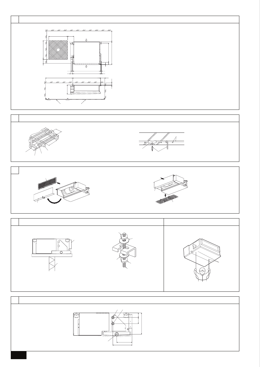
[Fig. 4.1.1] (P.2)
A
Ceiling board
B
Edge beam
C
Tie beam
D
Square timber for hanging the air conditioner
E
Pitch
For reinforced concrete construction
•
As shown in the figure below, fix the hanging bolts, or use square timbers to fix
the hanging bolts.
[Fig. 4.1.2] (P.2)
F
Insert: 100 to 150 kg (1 piece) (field supply)
G
M10 hanging bolt (field supply)
H
Reinforcement
Product Weight (kg)
Model name
20·25·32
PEFY-P-VML-A
18
5. Changing Bottom Inlet Specifications
1. Remove filter A (6 screws).
2. Remove the bottom plate B (6 screws) and bend the slit portion inwards at a
right angle.
[Fig. 5.0.1] (P.2)
A
Filter
B
Bottom plate
Caution:
When bending the bottom plate, be sure to protect yourself from its edges.
3. Fit the bottom plate B to the rear of the main body.
4. Fit filter A to the underside of the main body (6 screws).
[Fig. 5.0.2] (P.2)
A
Filter
B
Bottom plate
6. Installing the unit
6.1. Hanging the unit body
s
s
s
s
s
Bring the indoor unit to an installation site as it is packed.
s
s
s
s
s
To hang the indoor unit, use a lifting machine to lift and pass through the
hanging bolts.
[Fig. 6.1.1] (P.2)
A
Unit body
B
Lifting machine
[Fig. 6.1.2] (P.2)
C
Nuts (field supply)
D
Washers (field supply)
E
M10 hanging bolt (field supply)
6.2. Confirming the unit’s position and fix-
ing hanging bolts
s
s
s
s
s
Use the gage supplied with the panel to confirm that the unit body and
hanging bolts are positioned in place. If they are not positioned in place,
it may result in dew drops due to wind leak. Be sure to check the positional
relationship.
s
s
s
s
s
Use a level to check that the surface indicated by A
A
A
A
A
is at level. Ensure
that the hanging bolt nuts are tightened to fix the hanging bolts.
s
s
s
s
s
To ensure that drain is discharged, be sure to hang the unit at level using
a level.
[Fig. 6.2.1] (P.2)
Caution:
Be sure to install the unit body at level.
7. Refrigerant pipe and drain pipe specifications
To avoid dew drops, provide sufficient antisweating and insulating work to the re-
frigerant and drain pipes.
When using commercially available refrigerant pipes, be sure to wind commer-
cially available insulating material (with a heat-resisting temperature of more than
100 °C and thickness given below) onto both liquid and gas pipes.
Be also sure to wind commercially available insulating material (with a form
polyethylene’s specific gravity of 0.03 and thickness given below) onto all pipes
which pass through rooms.
1 Select the thickness of insulating material by pipe size.
Pipe size
Insulating material’s thickness
6.4 mm to 25.4 mm
More than 10 mm
28.6 mm to 38.1 mm
More than 15 mm
2 If the unit is used on the highest story of a building and under conditions of
high temperature and humidity, it is necessary to use pipe size and insulating
material’s thickness more than those given in the table above.
3 If there are customer’s specifications, simply follow them.
3.2. Securing installation and service space
•
Select the optimum direction of supply airflow according to the configuration of
the room and the installation position.
•
As the piping and wiring are connected at the bottom and side surfaces, and
the maintenance is made at the same surfaces, allow a proper space properly.
For the efficient suspension work and safety, provide a space as much as pos-
sible.
[Fig. 3.2.1] (P.2)
A
Access door
B
Electrical parts box
C
Air inlet
D
Air outlet
E
Ceiling surface
F
Service space
1
500 or more
2
100 or more
3
20 or more
4
300 or more
* If the optional long-life filter is installed, the dimensions of the air conditioner
increase.
Rear inlet:
Depth increases by 30 mm (*1)
Bottom inlet: Height increases by 30 mm (*2)
3.3. Combining indoor units with outdoor
units
For combining indoor units with outdoor units, refer to the outdoor unit installation
manual.
8
G
B
D
F
I
N
L
E
P
G
R
R
U
T
R
Caution:
•
Use refrigerant piping made of C1220 (CU-DHP) phosphorus deoxidized
copper as specified in the JIS H3300 “Copper and copper alloy seamless
pipes and tubes”. In addition, be sure that the inner and outer surfaces of
the pipes are clean and free of hazardous sulphur, oxides, dust/dirt, shav-
ing particles, oils, moisture, or any other contaminant.
•
Never use existing refrigerant piping.
- The large amount of chlorine in conventional refrigerant and refrigerator oil
in the existing piping will cause the new refrigerant to deteriorate.
•
Store the piping to be used during installation indoors and keep both
ends of the piping sealed until just before brazing.
- If dust, dirt, or water gets into the refrigerant cycle, the oil will deteriorate and
the compressor may fail.
•
Use Suniso 4GS or 3GS (small amount) refrigerator oil to coat the flare
and flange connection part. (For models using R22)
•
Use ester oil, ether oil or alkylbenzene (small amount) as the refrigerator
oil to coat flares and flange connections. (For models using R407C)
- The refrigerant used in the unit is highly hygroscopic and mixes with water
and will degrade the refrigerator oil.
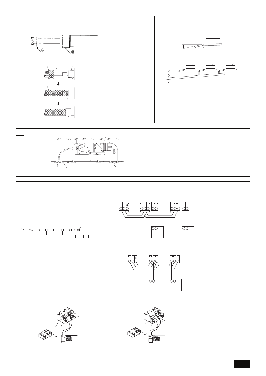
8.2. Drain piping work
1. Ensure that the drain piping is downward (pitch of more than 1/100) to the
outdoor (discharge) side. Do not provide any trap or irregularity on the way.
(1)
2. Ensure that any cross-wise drain piping is less than 20 m (excluding the differ-
ence of elevation). If the drain piping is long, provide metal braces to prevent it
from waving. Never provide any air vent pipe. Otherwise drain may be ejected.
3. Use a hard vinyl chloride pipe VP-25 (with an external diameter of 32 mm) for
drain piping.
4. Ensure that collected pipes are 10 cm lower than the unit body’s drain port as
shown in 2.
5. Do not provide any odor trap at the drain discharge port.
6. Put the end of the drain piping in a position where no odor is generated.
7. Do not put the end of the drain piping in any drain where ionic gases are
generated.
[Fig. 8.2.1] (P.3)
A
Downward slope 1/100 or more
B
Connection dia. R1 external thread
C
Indoor unit
D
Collective piping
E
Maximize this length to approx. 10 cm
9. Duct work
•
When connecting ducts, insert a canvas duct between the main body and the
duct.
•
Use non-combustible duct components.
•
Install sufficient thermal insulation to prevent condensation forming on outlet
duct flanges and outlet ducts.
Caution:
•
The noise from the intake will increase dramatically if intake A
A
A
A
A
is fitted
directly beneath the main body. Intake A
A
A
A
A
should therefore be installed as
far away from the main body as possible.
Particular care is required when using it with bottom inlet specifications.
•
To connect the air conditioner main body and the duct for potential equali-
zation.
•
Keep the distance between the inlet grille and the fan over 850 mm.
If it is less than 850 mm, install a safety guard not to touch the fan.
[Fig. 9.0.1] (P.3)
A
Air inlet
B
Air outlet
C
Access door
D
Ceiling surface
E
Canvas duct
F
Connect common reference potential wire between duct-work to air conditioner.
G
Air filter
H
Inlet grille
8. Connecting refrigerant pipes and drain pipes
8.1. Refrigerant piping work
This piping work must be done in accordance with the installation manuals for both
outdoor unit and BC controller (simultaneous cooling and heating series R2).
•
Series R2 is designed to operate in a system that the refrigerant pipe from an
outdoor unit is received by BC controller and branches at the BC controller to
connect between indoor units.
•
For constraints on pipe length and allowable difference of elevation, refer to
the outdoor unit manual.
•
The method of pipe connection is brazing connection.
Caution:
•
Install the refrigerant piping for the indoor unit in accordance with the
following.
1. Cut the tip of the indoor unit piping, remove the gas, and then remove the
brazed cap.
[Fig. 8.1.1] (P.3)
A
Cut here
B
Remove brazed cap
2. Pull out the thermal insulation on the site refrigerant piping, braze the unit
piping, and replace the insulation in its original position.
Wrap the piping with insulating tape.
Note:
•
Pay strict attention when wrapping the copper piping since wrapping the
piping may cause condensation instead of preventing it.
*
Before brazing the refrigerant piping, always wrap the piping on the main
body, and the thermal insulation piping, with damp cloths to prevent heat
shrinkage and burning the thermal insulation tubing. Take care to ensure
that the flame does not come into contact with the main body itself.
[Fig. 8.1.2] (P.3)
A
Thermal insulation
B
Pull out insulation
C
Wrap with damp cloth
D
Return to original position
E
Ensure that there is no gap here
F
Wrap with insulating tape
Cautions On Refrigerant Piping
s
s
s
s
s
Be sure to use non-oxidative brazing for brazing to ensure that no for-
eign matter or moisture enter into the pipe.
s
s
s
s
s
Be sure to apply refrigerating machine oil over the flare connection seat-
ing surface and tighten the connection using a double spanner.
s
s
s
s
s
Provide a metal brace to support the refrigerant pipe so that no load is
imparted to the indoor unit end pipe. This metal brace should be pro-
vided 50 cm away from the indoor unit’s flare connection.
Warning:
When installing and moving the unit, do not charge it with refrigerant other
than the refrigerant (R407C or R22) specified on the unit.
- Mixing of a different refrigerant, air, etc. may cause the refrigerant cycle to mal-
function and result in severe damage.
7.1. Refrigerant pipe and drain pipe specifi-
cations
Item
Model
20·25·32
Liquid pipe
ø 6.35
Gas pipe
ø 12.7
Drain pipe
R1 (External thread)
Refrigerant pipe
(Brazing connection)
7.2. Refrigerant pipe, drain pipe and filling
port
[Fig. 7.2.1] (P.2)
A
Refrigerant pipe (liquid pipe): HP
B
Refrigerant pipe (gas pipe): LP
C
Drain pipe
9
G
B
D
F
I
N
L
E
P
G
R
R
U
T
R
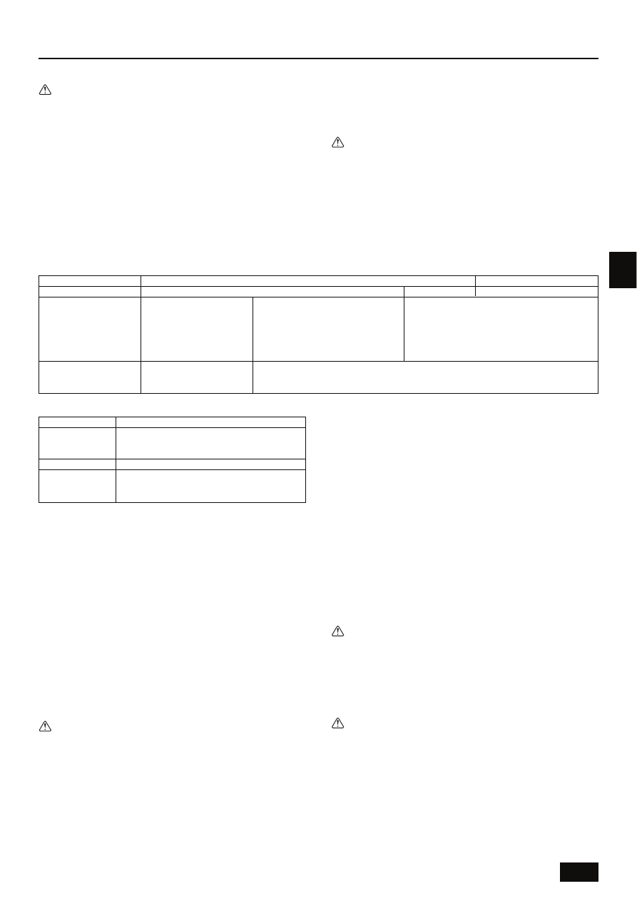
<Table 1>
System configuration
For a single-refrigerant system
For a multi-refrigerant system
Transmission cable length
Less than 120 m
More than 120 m
Regardless of length
Facility example
(for noise judgment)
Types of transmission
cables
Residence or independent store
without noise
VCTF, VCTFK, CVV, CVS, VVR,
VVF, VCT or shielding wire
CVVS or CPEVS
Building, clinic, hospital or communications
station without noise supposedly generated
from inverter equipment, private power gen-
erator, high-frequency medical equipment,
radio-used communications equipment and
so on
All facilities
Shielding wire CVVS or CPEVS
2. Remote controller cables
Network remote controller
Types of cables
Non-shielding wire for up to 10 m; the same specifica-
tions as “1.” Wiring transmission cables for more than
10 m
Cable diameter
More than 0.5 to 0.75 mm
2
Length
Add any portion in excess of 10 m to within the longest
allowable transmission cable length 200 m (Shielding
portion is more than 1.25 mm
2
)
10.1. Power supply wiring
•
Power supply cords of appliances shall not be lighter than design 245 IEC or
227 IEC.
•
A switch with at least 3 mm contact separation in each pole shall be provided
by the Air conditioner installation.
Power cable size: more than 1.5 mm
2
[Fig. 10.1.1] (P.3)
A
Switch 16 A
B
Overcurrent protection 16 A
C
Indoor unit
D
Total operating current be less than 16 A
E
Pull box
[Selecting non-fuse breaker (NF) or earth leakage breaker (NV)]
To select NF or NV instead of a combination of Class B fuse with switch, use the
following:
•
In the case of Class B fuse rated 15 A or 20 A,
NF model name (MITSUBISHI): NF30-CS (15 A) (20 A)
NV model name (MITSUBISHI): NV30-CA (15 A) (20 A)
Use an earth leakage breaker with a sensitivity of less than 30 mA 0.1 s.
Caution:
Do not use anything other than the correct capacity breaker and fuse. Using
fuse, wire or copper wire with too large capacity may cause a risk of mal-
function or fire.
10.2. Connecting remote controller, indoor
and outdoor transmission cables
•
Connect indoor unit TB5 and outdoor unit TB3. (Non-polarized 2-wire)
The “S” on indoor unit TB5 is a shielding wire connection. For specifications
about the connecting cables, refer to the outdoor unit installation manual.
•
Install a remote controller following the manual supplied with the remote con-
troller.
•
Connect the “1” and “2” on indoor unit TB15 to a MA remote controller. (Non-
polarized 2-wire)
•
Connect the “M1” and “M2” on indoor unit TB5 to a M-NET remote controller.
(Non-polarized 2-wire)
•
Connect the remote controller’s transmission cable within 10 m using a 0.75 mm
2
core cable. If the distance is more than 10 m, use a 1.25 mm
2
junction cable.
[Fig. 10.2.1] (P.3) MA Remote controller
[Fig. 10.2.2] (P.3) M-NET Remote controller
A
Terminal block for indoor transmission cable
B
Terminal block for outdoor transmission cable
C
Remote controller
•
DC 9 to 13 V between 1 and 2 (MA remote controller)
•
DC 24 to 30 V between M1 and M2 (M-NET remote controller)
[Fig. 10.2.3] (P.3) MA Remote controller
[Fig. 10.2.4] (P.3) M-NET Remote controller
A
Non-polarized
B
Upper level (TB15)
C
Remote Controller
D
Lower level (TB5)
•
The MA remote controller and the M-NET remote controller cannot be used at
the same time or interchangeably.
Caution:
Install wiring so that it is not tight and under tension. Wiring under tension
may break, or overheat and burn.
•
Fix power source wiring to control box by using buffer bushing for tensile force.
(PG connection or the like.) Connect transmission wiring to transmission ter-
minal block through the knockout hole of control box using ordinary bushing.
•
After wiring is complete, make sure again that there is no slack on the connec-
tions, and attach the cover onto the control box in the reverse order removal.
Caution:
Wire the power supply so that no tension is imparted. Otherwise disconnec-
tion, heating or fire result.
10.3. Connecting electrical connections
Please identify the model name of the operation manual attached on the terminal
bed box cover with that shown on the rating name plate.
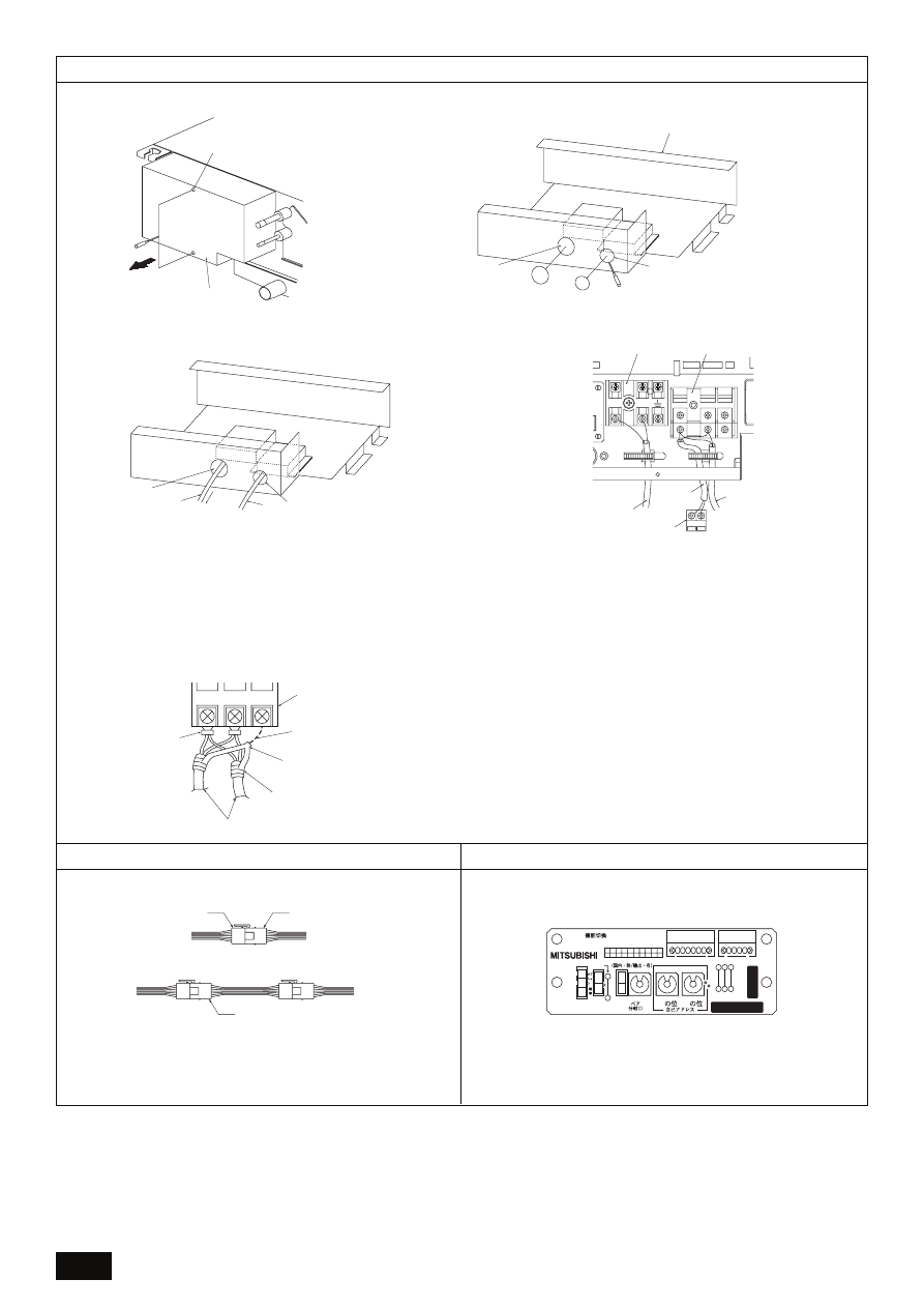
1. Remove the screw (2pcs) holding the cover to dismount the cover.
[Fig. 10.3.1] (P.4)
A
Screw holding cover (2pcs)
B
Cover
10. Electrical wiring
Precautions on electrical wiring
Warning:
Electrical work should be done by qualified electrical engineers in accord-
ance with “Engineering Standards For Electrical Installation” and supplied
installation manuals. Special circuits should also be used. If the power cir-
cuit lacks capacity or has an installation failure, it may cause a risk of elec-
tric shock or fire.
1. Be sure to take power from the special branch circuit.
2. Be sure to install an earth leakage breaker to the power.
3. Install the unit to prevent that any of the control circuit cables (remote control-
ler, transmission cables) is brought in direct contact with the power cable out-
side the unit.
4. Ensure that there is no slack on all wire connections.
5. Some cables (power, remote controller, transmission cables) above the ceiling
may be bitten by mouses. Use as many metal pipes as possible to insert the
cables into them for protection.
6. Never connect the power cable to leads for the transmission cables. Otherwise
the cables would be broken.
7. Be sure to connect control cables to the indoor unit, remote controller, and the
outdoor unit.
8. Put the unit to the ground on the outdoor unit side.
9. Select control cables from the conditions given in page 9.
Caution:
Be sure to put the unit to the ground on the outdoor unit side. Do not con-
nect the earth cable to any gas pipe, water pipe, lightening rod, or telephone
earth cable. Incomplete grounding may cause a risk of electric shock.
Types of control cables
1. Wiring transmission cables
•
Types of transmission cables
Design wiring in accordance with the following table <Table 1>.
•
Cable diameter
More than 1.25 mm
2

10
G
B
D
F
I
N
L
E
P
G
R
R
U
T
R
2. Open knockout holes
(Recommend to use a screwdriver or the like for this work.)
[Fig. 10.3.2] (P.4)
A
Terminal bed box
B
Knockout hole
C
Remove
D
Knockout hole
3. Fix power source wiring to terminal bed box by using buffer bushing for tensile
force. (PG connection or the like.) Connect transmission wiring to transmission
terminal bed through the knockout hole of terminal bed box using ordinary
bushing.
[Fig. 10.3.3] (P.4)
E
To prevent external tensile force from applying to the wiring connection section of
power source terminal bed use buffer bushing like PG connection or the like.
F
Power source wiring
G
Tensile force
H
Use ordinary bushing
I
Transmission wiring
4. Connect the power source, transmission and remote controller wiring. The dis-
mounting of the terminal bed box is not needed.
[Fig. 10.3.4] (P.4)
J
Power source terminal bed
K
Terminal bed for indoor transmission
L
To 1-phase power source
M
Transmission line DC 30 V
N
Terminal bed for outdoor transmission line (TB3)
O
Transmission line to the remote controller, terminal bed for indoor unit and BC
controller
[Shield wire connection]
[Fig. 10.3.5] (P.4)
A
Terminal bed
B
Round terminal
C
Shield wire
D
Two shield wires may be connected together at the shield relay terminal bed
E
One shield wire is connected with another shield wire. (Terminal connection)
F
Insulation tape (for the earthing of shield and the prevention of contact to trans-
mission terminal)
5. After wiring is complete, make sure again that there is no slack on the connec-
tions, and attach the cover onto the terminal bed box in the reverse order of
removal.
Notes:
•
Do not pinch the cables or wires when attaching the terminal bed box
cover. Doing so may cause a risk of disconnection.
•
When accommodating the terminal bed box, make sure that the connec-
tors on the box side are not removed. If removed, it cannot operate nor-
mally.
10.4. Selecting the power source
It is 240V, 230V setting at factory shipment.
So, it is necessary to change the setting in other power supply districts.
Please remove the connector of motor from the control box, and insert the attach-
ment connector according to each power supply between those.
The connector colors are as follows.
Power source
240V
230V
220V
Color
White
Blue
[Fig. 10.4.1] (P.4)
A
Terminal bed box connector (White)
B
Motor connector (White)
C
Attachment connector (Blue) (Accessory)
10.5. Setting addresses
(Be sure to operate with the main power turned OFF.)
[Fig. 10.5.1] (P.4)
<Address board>
•
There are two types of rotary switch setting available: setting addresses 1 to 9
and over 10, and setting branch numbers.
1 How to set addresses
Example: If Address is “3”, remain SW12 (for 1 to 9) at “0”, and match
SW11(for over 10) with “3”.
2 How to set branch numbers (Series R2 only)
Match the indoor unit’s refrigerant pipe with the BC controller’s end connec-
tion number. Remain other than R2 at “0”.
•
The rotary switches are all set to “0” when shipped from the factory. These
switches can be used to set unit addresses and branch numbers at will.
•
The determination of indoor unit addresses varies with the system at site. Set
them referring to technical data.
Notes:
Please set the switch SW5 according to the power supply voltage.
•
Set SW5 to 240V side when the power supply is 230 and 240 volts.
•
When the power supply is 220 volts, set SW5 to 200V side.
10.6. Sensing room temperature with the
built-in sensor in a remote controller
If you want to sense room temperature with the built-in sensor in a remote control-
ler, set SW1-1 on the control board to “ON”.
Wyszukiwarka
Podobne podstrony:
IM PEFY P15 63VMS1 L E KB79H130H03 GB 08 2009
IM PEFY P VMM A WT03199X02 2004
IM PEFY P 20 140VMM E WT04197X01 08 2005
IM PEFY P40 250VMH E WT04198X02 GB 2005
IM PEFY P VM A WT03198X03 2001
60 Rolle der Landeskunde im FSU
IM 5 dyfuzja wyklad 03
jadłospis, Turystyka i Rekreacja UW im. MSC, IV Semestr, Żywienie Człowieka
Problemy w małżeństwie i przeciwdziałanie im, konspekty, KONSPEKT, wych.do.życia, klasa II
praca-magisterska-7092, 1a, prace magisterskie Politechnika Krakowska im. Tadeusza Kościuszki
praca-magisterska-7091, 1a, prace magisterskie Politechnika Krakowska im. Tadeusza Kościuszki
NA kolosa Z IM
Uczelnia Warszawska im
Biogasanlagen im EEG 2009
Datenblaetter im Web
IM wykład 1
6 rozdział IM
więcej podobnych podstron