Air-Conditioners For Building Application
INDOOR UNIT
PEFY-P-VML-A
PLFY-P-VLMD-A
PEFY-P-VMM-A
PDFY-P-VM-A
PEFY-P-VMH-A
PFFY-P-VLEM-A
PFFY-P-VLRM-A
OPERATION MANUAL
For safe and correct use, please read this operation manual thoroughly before operating the air-conditioner unit.
BEDIENUNGSHANDBUCH
Zum sicheren und einwandfreien Gebrauch der Klimaanlage dieses Bedienungshandbuch vor Inbetriebnahme gründlich durchlesen.
MANUEL D’UTILISATION
Pour une utilisation correcte sans risques, veuillez lire le manuel d’utilisation en entier avant de vous servir du climatiseur.
MANUAL DE INSTRUCCIONES
Lea este manual de instrucciones hasta el final antes de poner en marcha la unidad de aire acondicionado para garantizar un uso seguro y
correcto.
ISTRUZIONI DI FUNZIONAMENTO
Leggere attentamente questi istruzioni di funzionamento prima di avviare l’unità, per un uso corretto e sicuro della stessa.
BEDIENINGSHANDLEIDING
Voor een veilig en juist gebruik moet u deze bedieningshandleiding grondig doorlezen voordat u de airconditioner gebruikt.
MANUAL DE OPERAÇÃO
Para segurança e utilização correctas, leia atentamente o manual de operação antes de pôr a funcionar a unidade de ar condicionado.
E°XEIPI¢IO O¢H°IøN XPH™Eø™
°È· ·ÛÊ¿ÏÂÈ· Î·È ÛˆÛÙ‹ ¯Ú‹ÛË, ·Ú·Î·Ï›ÛÙ ‰È·‚¿ÛÂÙ ÚÔÛ¯ÙÈο ·˘Ùfi ÙÔ ÂÁ¯ÂÈÚ›‰ÈÔ ¯Ú‹Ûˆ˜ ÚÈÓ ı¤ÛÂÙ Û ÏÂÈÙÔ˘ÚÁ›· ÙË
ÌÔÓ¿‰· ÎÏÈÌ·ÙÈÛÌÔ‡.
РУКОВОДСТВО ПО ЭКСПЛУАТАЦИИ
Для обеспечения правильного и безопасного использования следует ознакомиться с инструкциями, указанными в данном
руководстве по эксплуатации, тщательным образом до того, как приступать к использованию кондиционера.
IfiLETME ELK‹TABI
Emniyetli ve do¤ru biçimde nas›l kullan›laca¤›n› ö¤renmek için lütfen klima cihaz›n› iflletmeden önce bu elkitab›n› dikkatle okuyunuz.
G
B
D
F
I
N
L
E
P
G
R
R
U
T
R
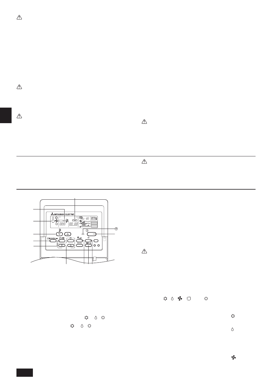
1
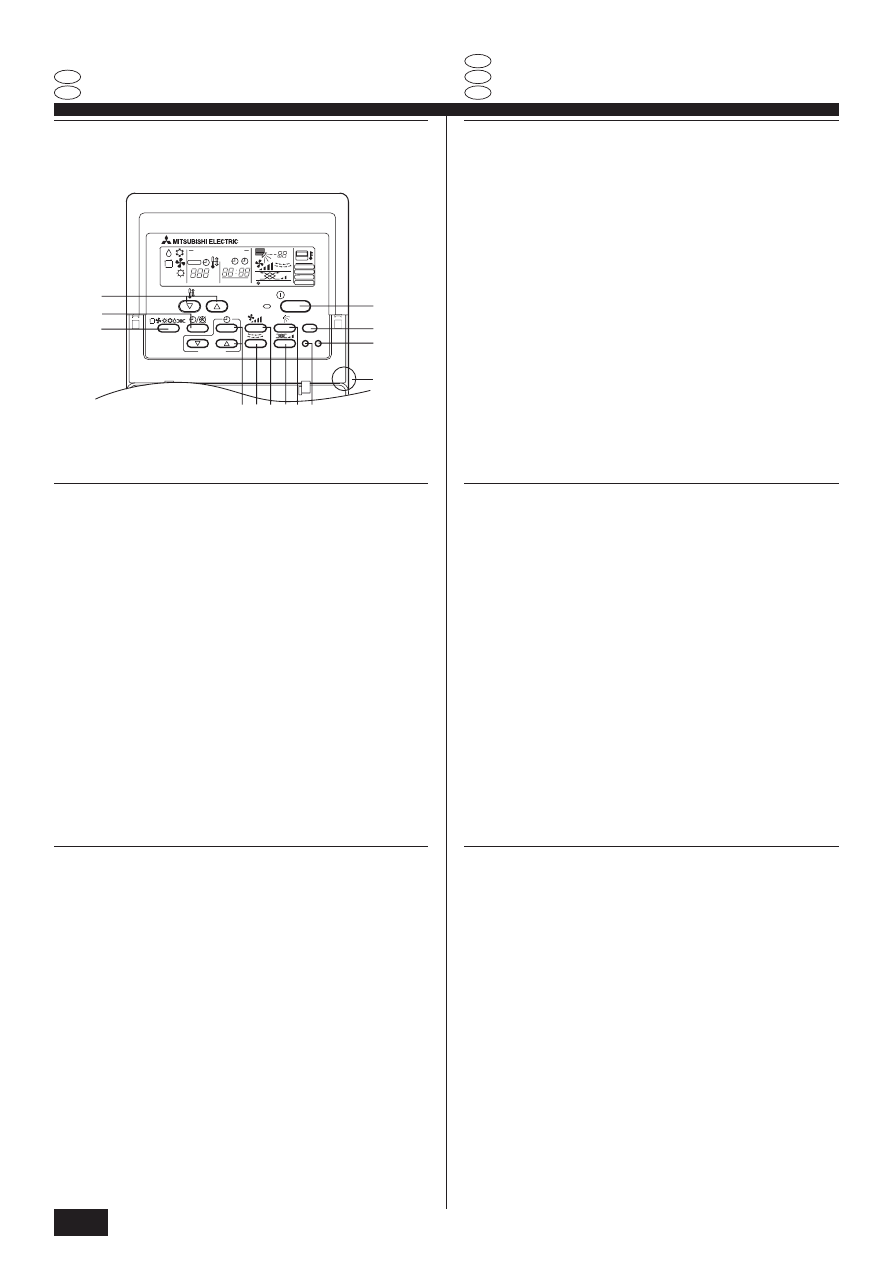
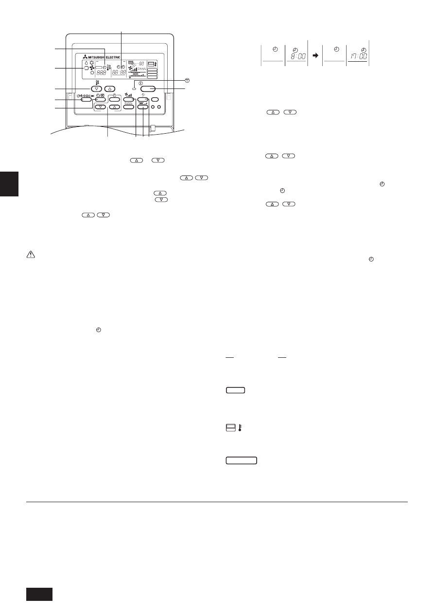
[Room temperature adjustment] Button
2
[Timer/continuous] Button
3
[Selecting operation] Button
4
[Time selection] Button
[Time-setting] Button
5
[Louver] Button
6
[Fan speed adjustment] Button
7
[Up/down airflow direction] Button
8
[Ventilation] Button
9
[Checking/built-in] Button
0
[Test run] Button
A
[Filter] Button
B
[ON/OFF] Button
C
Position of built-in room temperature
•
Never expose the remote controller to direct sunlight. Doing so can result in
the erroneous measurement of room temperature.
•
Never place any obstacle around the lower right-hand section of the remote
controller. Doing so can result in the erroneous measurement of room tem-
perature.
Remote controller-Button
Fernbedienungs-Taste
PAR-20MAA
ON/OFF
CENTRALLY CONTROLLED
ERROR CODE
CLOCK
ON OFF
˚C
CHECK
CHECK MODE
FILTER
TEST RUN
FUNCTION
˚C
1Hr.
NOT AVAILABLE
STAND BY
DEFROST
FILTER
CHECK TEST
TEMP.
TIMER SET
1
2
3
4 5 6 8 7 9
0
C
A
B
1
Raumtemperatur-Tasten
2
Zeitschalter-/Dauerbetrieb-Taste
3
Betriebsart-Taste
4
Zeitumschalt-Taste
Zeiteinstell-Tasten
5
Klappen-Taste
6
Luftstromgeschwindigkeit-Taste
7
Vertikale luftstromrichtung-Tasten
8
Belüftung-Tasten
9
Überprüfen/Eingebauten-Tasten
0
Testlauf-Tasten
A
Filter-Taste
B
Betrieb-/Stop-Taste
C
Position der eingebauten Raumtemperatur
•
Die Fernbedienung nicht direkter Sonneneinstrahlung aussetzen. Die Raum-
temperatur wird sonst nicht korrekt gemessen.
•
Den rechten unteren Teil der Fernbedienung nicht blockieren. Die Raum-
temperatur wird sonst nicht korrekt gemessen.
1
Touche de [réglage de la température de la pièce]
2
Touche de [fonctionnement continu/minuterie]
3
Touche de [sélection du mode de fonctionnement]
4
Touche de [sélection de l’heure]
Touche de [réglage de l’heure]
5
Touche de [pivotement]
6
Touche de [réglage de la vitesse du ventilateur]
7
Touche de [sens de la soufflerie vers le haut/vers le bas]
8
Touche [Ventilation]
9
Touche [Vérification/Intégré]
0
Touche [Essai de fonctionnement]
A
Touche de [filtre]
B
Touche [ON/OFF]
C
Position du capteur intégré de la température de la pièce
•
Ne jamais laisser la commande à distance en plein soleil sinon les données de
température ambiante risquent d’être erronées.
•
Ne jamais placer d’obstacle devant la partie inférieure droite de la commande
à distance sinon la lecture des températures ne sera pas correcte.
1
Pulsante [Regolazione della temperatura ambiente]
2
Pulsante [Timer/continuo]
3
Pulsante [Selezione modalità di funzionamento]
4
Pulsante [Selezione ora]
Pulsante [Impostazione dell’ora]
5
Pulsante [Regolazione deflettore]
6
Pulsante [Regolazione della velocità di ventilazione]
7
Pulsante [Regolazione della direzione di soffiaggio verso l’alto/il basso]
8
Pulsante [Ventilazione]
9
Pulsante [Controllo/Incorporata]
0
Pulsante [Prova di funzionamento]
A
Pulsante [Filtro]
B
Pulsante [ACCENSIONE/SPEGNIMENTO]
C
Posizione temperatura ambiente incorporata
•
Non esporre mai il comando a distanza alla luce diretta del sole, in quanto
questo può alterare la corretta rilevazione della temperatura ambiente.
•
Non porre alcun ostacolo attorno alla sezione inferiore destra del comando a
distanza, in quanto questo può alterare la corretta rilevazione della temperatu-
ra ambiente.
1
Botón [Ajuste de la temperatura de la habitación]
2
Botón [Temporizador/continuo]
3
Botón [Selección del modo de funcionamiento]
4
Botón [Selección de la hora]
Botón [Determinación de la hora]
5
Botón [Persiana]
6
Botón [Ajuste de la velocidad del ventilador]
7
Botón [Dirección de la corriente ascendente/descendente de aire]
8
Botón [Ventilación]
9
Botón [Comprobación/Incorporada]
0
Botón [Prueba de funcionamiento]
A
Botón [Filtro]
B
Botón [ON/OFF]
C
Posición de temperatura ambiente incorporada
•
Nunca exponga el mando a distancia a la luz directa del sol. Si lo hace, se
producirá una lectura errónea de la temperatura de la habitación.
•
Nunca ponga ningún obstáculo alrededor de la sección inferior derecha del
mando a distancia. Si lo hace, se producirá una lectura errónea de la tempera-
tura de la habitación.
Touche Commande à distance
Bottone dell’unità del comando a distanza
Controlador remoto-Botón
2
F
I
E
GB
D
3
G
B
D
F
I
N
L
E
P
G
R
R
U
T
R
NL
P
GR
RU
TR
1
[Aanpassen kamertemperatuur] Knop
2
[Timer/continu] Knop
3
[Standselectie] Knop
4
[Tijdselectie] Knop
[Tijdinstellings] Knop
5
[Ventilatie-jaloezie] Knop
6
[Aanpassen van de ventilatorsnelheid] Knop
7
[Blaasrichting naar boven/ naar beneden] Knop
8
Knop [Ventilatie]
9
Knop [Controle/Ingebouwde]
0
Knop [Proefdraaien]
A
[Filter] Knop
B
[ON/OFF (AAN/UIT)] Knop
C
Plaats van ingebouwde kamertemperatuursensor
•
Laat de afstandsbediening nooit in direct zonlicht liggen. Als u dit toch doet
kan het zijn dat de kamertemperatuur onjuist gemeten wordt.
•
Zet of hang nooit iets in de buurt van het gedeelte rechtsonder op de
afstandsbediening. Als u dit toch doet kan het zijn dat de kamertemperatuur
onjuist gemeten wordt.
1
Кнопка [Регули ование темпе ату ы в помещении]
2
Кнопка [Тайме /постоянно]
3
Кнопка [Выбо опе ации]
4
Кнопка [Выбо в емени]
Кнопка [Наст ойка в емени]
5
Кнопка [жалюзи]
6
Кнопка [Регули овки ско ости вентилято а]
7
Кнопка [Нап авления потока воздуха вве х/вниз]
8
Кнопка [Вентиляция]
9
Кнопка [П ове ка/вст оенного датчика]
0
Кнопка [Тестовый п огон]
A
Кнопка [Фильт ]
B
Кнопка [ВКЛ./ВЫКЛ.]
C
Позиция вст оенного датчика темпе ату ы помещения
•
Никогда не подве гайте пульт дистанционного уп авления воздействию
п ямых солнечных лучей. Это может п ивести к неп авильным
заме ениям темпе ату ы в помещении.
•
Никогда не помещайте какое-либо п епятствие пе ед нижней п авой
секцией пульта дистанционного уп авления. Это может п ивести к
неп авильному заме ению темпе ату ы в помещении.
1
[Oda S›cakl›¤› Ayar›] Dü¤mesi
2
[Saatli/Sürekli Çal›flma] Dü¤mesi
3
[Program Seçme] Dü¤mesi
4
[Saat Seçme] Dü¤mesi
[Saat Ayar›] Dü¤mesi
5
[Pancur] Dü¤mesi
6
[Vantilatör H›z› Ayarlama] Dü¤mesi
7
[Hava Ak›m›n› Afla¤›/Yukar› Yönlendirme] Dü¤mesi
8
[Havaland›rma] Dü¤me
9
[Kontrol/Entegre] Dü¤me
0
[Deneme Çal›flt›rmas›] Dü¤me
A
[Filtre] Dü¤mesi
B
[Açma/Kapama] Dü¤mesi
C
Entegre oda s›cakl›¤› konumu
•
Uzaktan kumanda ünitesini günefl ›fl›¤›na maruz b›rakmay›n. Aksi taktirde oda
s›cakl›¤›n›n yanl›fl ölçülmesine neden olabilirsiniz.
•
Uzaktan kumanda ünitesinin sa¤ alt köflesinin önünü hiçbir flekilde kapatmay›n.
Aksi taktirde oda s›cakl›¤›n›n yanl›fl ölçülmesine neden olabilirsiniz.
1
Tecla de [regulação da temperatura da peça]
2
Tecla de [temporização/contínuo]
3
Tecla de [selecção de funcionamento]
4
Tecla de [selecção da hora]
Tecla de [programação da hora]
5
Tecla [Veneziana]
6
Tecla de [regulação da velocidade da ventoinha]
7
Tecla de [direcção do fluxo de ar para cima/para baixo]
8
Botão [Ventilação]
9
Botão [Verificação/Incorporada]
0
Botão [Teste de funcionamento]
A
Tecla [filtro]
B
Tecla [ON/OFF] (Ligar/Desligar)
C
Posição da temperatura ambiente incorporada
•
Nunca exponha o controlo remoto à luz directa do sol, porque pode dar-lhe
valores de temperatura da peça anormais.
•
Nunca coloque nenhum obstáculo em volta da secção inferior direita do con-
trolo remoto, pois isso pode dar-lhe valores de temperatura da peça anormais.
1
∫ Ô˘Ì › [ƒ‡ıÌÈÛ˘ ıÂÚÌÔÎÚ·Û›·˜ ‰ˆÌ·Ù›Ô˘]
2
∫ Ô˘Ì › [ÃÚÔÓfiÌÂÙÚÔ/Û˘Ó¯‹˜]
3
∫ Ô˘Ì › [∂ ÎÏÔÁ‹˜ ÏÂÈÙÔ˘ÚÁ›·˜]
4
∫ Ô˘Ì › [∂ ÎÏÔÁ‹˜ ¯ÚfiÓÔ˘]
∫ Ô˘Ì › [ƒ‡ıÌÈÛ˘ ÒÚ·˜]
5
∫ Ô˘Ì › [ÁÚ›ÏÏÈ·˜]
6
∫ Ô˘Ì › [ƒ‡ıÌÈÛ˘ Ù·¯‡ÙËÙ·˜ ·ÓÂÌÈÛÙ‹Ú·]
7
∫ Ô˘Ì › [¶¿Óˆ/οو ηÙ‡ı˘ÓÛ˘ ÚÔ‹˜ ·¤Ú·]
8
∫ Ô˘Ì › [∂ Í·ÂÚÈÛÌÔ‡]
9
∫ Ô˘Ì › [∂ ϤÁ¯Ô˘/ÂÓۈ̷و̤ÓÔ˘]
0
∫ Ô˘Ì › [¢ÔÎÈÌ·ÛÙÈ΋˜ ÏÂÈÙÔ˘ÚÁ›·˜]
A
∫ Ô˘Ì › [Ê›ÏÙÚÔ˘]
B
∫ Ô˘Ì › [ON/OFF]
C
£¤ÛË ÙÔ˘ ÂÓۈ̷و̤ÓÔ˘ ıÂÚÌfiÌÂÙÚÔ˘ ‰ˆÌ·Ù›Ô˘
•
ªËÓ ÂÎÙ›ıÂÙ ÔÙ¤ ÙÔ ¯ÂÈÚÈÛÙ‹ÚÈÔ ÂÍ · ÔÛÙ¿Ûˆ˜ ÛÙÔ ËÏÈ·Îfi ÊÒ˜.
∞˘Ùfi
Ì ÔÚ› Ó· ¤¯ÂÈ Û·Ó · ÔÙ¤ÏÂÛÌ· Ï·Óı·Ṳ̂Ó˜ ÌÂÙÚ‹ÛÂȘ Ù˘ ıÂÚÌÔÎÚ·Û›·˜
‰ˆÌ·Ù›Ô˘.
•
ªËÓ ÙÔ ÔıÂÙ›Ù ÔÙ¤ ÂÌ fi‰È· Á‡Úˆ · fi ÙÔ Î¿Ùˆ ‰ÂÍÈfi ÙÌ‹Ì· ÙÔ
¯ÂÈÚÈÛÙËÚ›Ô˘ ÂÍ · ÔÛÙ¿Ûˆ˜.
∞˘Ùfi Ì ÔÚ› Ó· ¤¯ÂÈ Û·Ó · ÔÙ¤ÏÂÛÌ·
Ï·Óı·Ṳ̂Ó˜ ÌÂÙÚ‹ÛÂȘ Ù˘ ıÂÚÌÔÎÚ·Û›·˜ ‰ˆÌ·Ù›Ô˘.
Knop afstandbediening
Botão do controlo remoto
∆ËϯÂÈÚÈÛÙ‹ÚÈÔ-∫ Ô˘Ì ›
Кнопка конт олле а ДУ
Uzaktan kumanda ünitesi - Dü¤me
4
G
B
D
F
I
N
L
E
P
G
R
R
U
T
R
F
I
E
GB
D
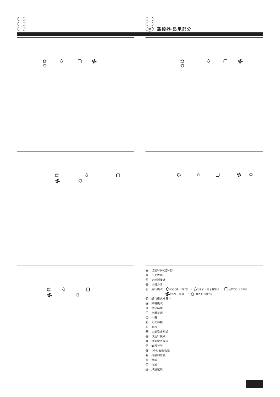
A
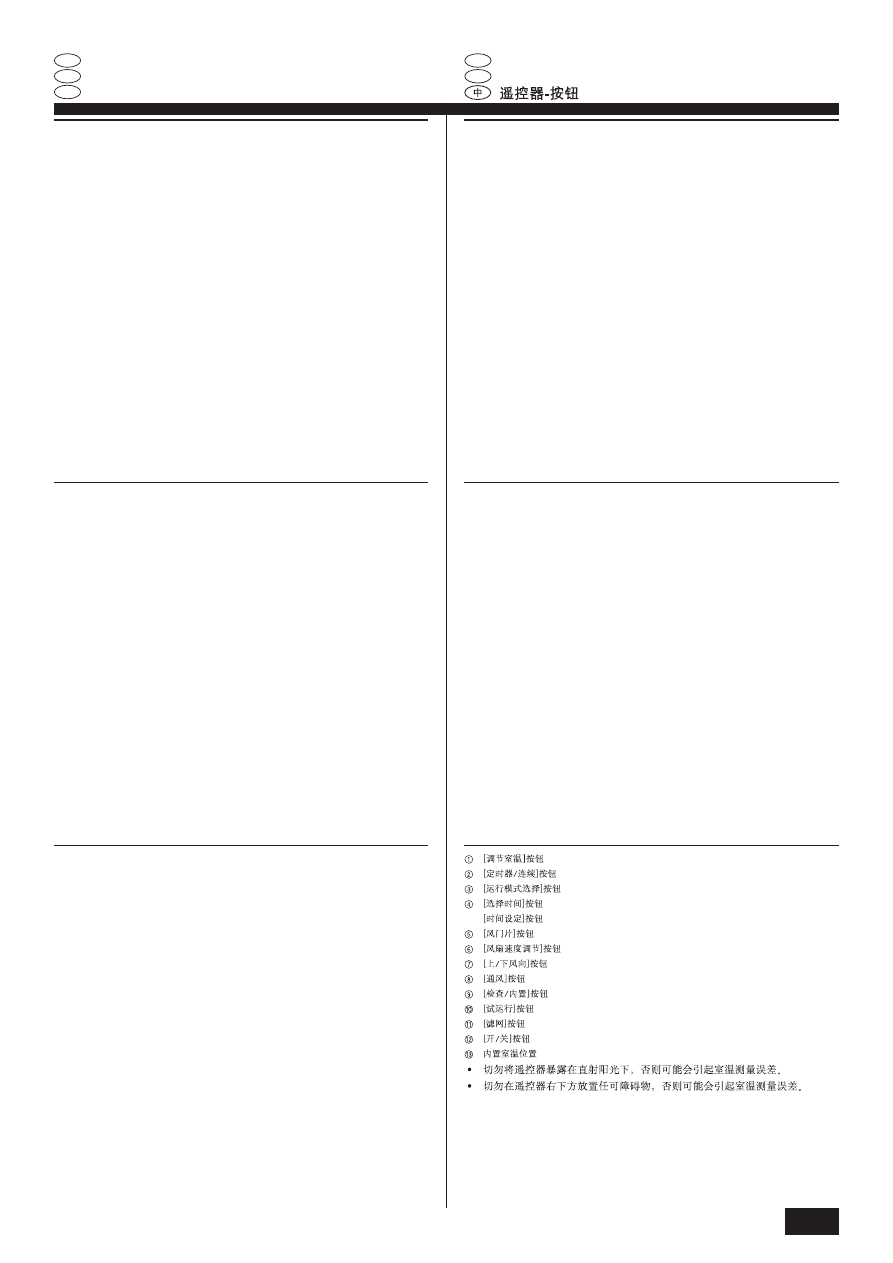
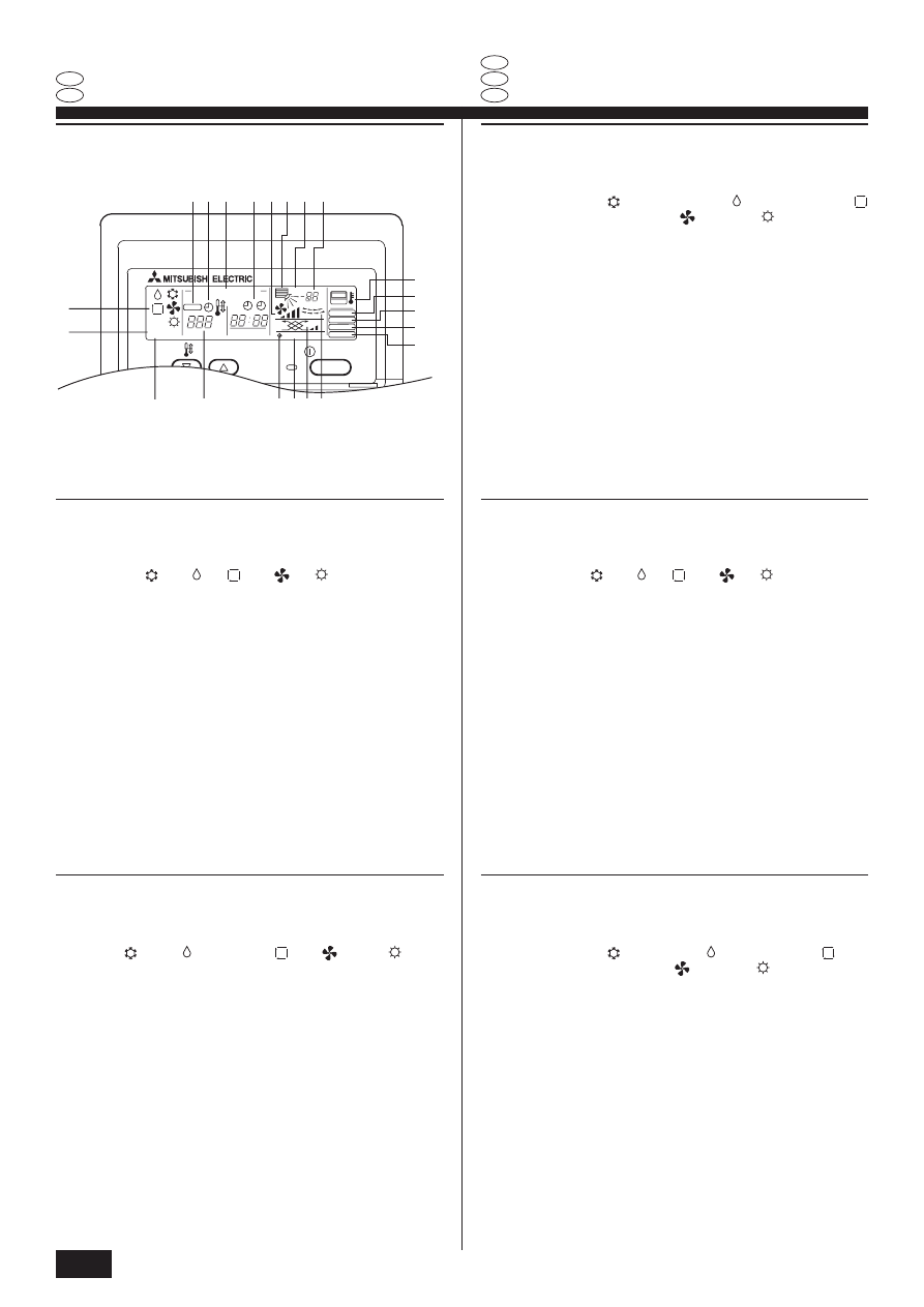
Current time/Timer
B
Centralized control
C
Timer ON
D
Abnormality occurs
E
Operation mode:
COOL, DRY,
AUTO,
FAN,
HEAT
F
Preparing for Heating mode
G
Defrost mode
H
Set temperature
I
Power ON
J
Louver
K
Not available function
L
Ventilation
M
Function setting mode
N
Test run mode
O
Error check mode
P
Filter sign
Q
Set effective for 1 hr.
R
Sensor position
S
Room temperature
T
Airflow
U
Fan speed
ON/OFF
CENTRALLY CONTROLLED
ERROR CODE
CLOCK
ON OFF
˚C
CHECK
CHECK MODE
FILTER
TEST RUN
FUNCTION
˚C
1Hr.
NOT AVAILABLE
STAND BY
DEFROST
TEMP.
A
B
C
D
E
F
H
I KL J
M
P
N
O
R
S
Q
T
U
G
A
Heure/Programmateur
B
Contrôle centralisé
C
Programmateur activé (ON)
D
En cas d’anomalie
E
Mode de fonctionnement:
REFROIDDISSEMENT,
DESHUMIDIFICATION,
AUTOMATIQUE,
SOUFFLERIE,
CHAUFFAGE
F
Préparation pour le mode chauffage
G
Mode dégivrage
H
Réglage de la température
I
Mise sous tension (ON)
J
Lucarne
K
Fonction non disponible
L
Ventilation
M
Mode de réglage du fonctionnement
N
Mode d’essai de fonctionnement
O
Mode de vérification des erreurs
P
Signe du filtre
Q
Réglage après une heure
R
Position du capteur
S
Température de la pièce
T
Flux d’air
U
Vitesse du ventilateur
A
Ora corrente/Timer
B
Comando centralizzato
C
Timer attivato
D
Si verifica un’anomalia
E
Modo funzionamento:
COOL, DRY,
AUTO,
FAN,
HEAT
F
Preparazione della modalità di riscaldamento
G
Modalità di sbrinamento
H
Impostazione temperatura
I
Alimentazione attivata
J
Deflettore
K
Funzione non disponibile
L
Ventilazione
M
Modalità impostazione funzione
N
Modalità di prova di funzionamento
O
Modalità di controllo errore
P
Simbolo del filtro
Q
Impostazione effettiva di un’ora
R
Posizione del sensore
S
Temperature ambiente
T
Flujo de aire
U
Velocità di ventilazione
A
Hora actual/Temporizador
B
Control centralizado
C
Temporizador en ON
D
Se producen anomalías
E
Modo de funcionamiento:
REFRIGERACIÓN,
DESHUMIDIFICACIÓN,
MODO
AUTOMÁTICO,
VENTILADOR,
CALEFACCIÓN
F
Preparación para el modo Calefacción
G
Modo Descongelación
H
Temperatura programada
I
Activado
J
Rejilla
K
Función no disponible
L
Ventilación
M
Modo de configuración de funciones
N
Modo de prueba de funcionamiento
O
Modo de comprobación de errores
P
Señal del filtro
Q
Valor activado por una hora
R
Posición del sensor
S
Temperatura ambiente
T
Flusso d’aria
U
Velocidad del ventilador
A
Aktuelle Zeit/Timer (Zeitschalter)
B
Anzeige für Zentralsteuerung
C
Zeitschalter/Timer ON/EIN
D
Auftretende Abnormität
E
Betriebsart:
KÜHLEN,
LUFTTROCKNEN,
AUTO,
GEBLÄSE,
HEIZEN
F
Vorbereitung zur Betriebsart Heizen
G
Betriebsart Enteisen
H
Eingestellten Temperatur
I
Netz ON/EIN
J
Luftklappe
K
Funktion nicht verfügbar
L
Ventilation
M
Betriebsart Funktion einstellen
N
Betriebsart Testlauf
O
Betriebsart Fehlerprüfung
P
Filterzeichen
Q
1 Stunde wirksame Einstellung
R
Fühlerposition
S
Raumtemperatur
T
Luftstrom
U
Luftstromgeschwindigkeit
Remote controller-Display
Fernbedienung-Anzeige
Affichage Commande à distance
Display dell’unità del comando a distanza
Controlador remoto-Indicador
5
G
B
D
F
I
N
L
E
P
G
R
R
U
T
R
NL
P
GR
RU
TR
A
Текущее в емя/Тайме
B
Цент ализованного конт оля
C
Тайме ВКЛ. (ON)
D
В случае неполадки
E
Режим эксплуатации:
ОХЛАЖДЕНИЕ,
СУШКА,
АВТО,
ВЕНТИЛЯТОР,
ОБОГРЕВ
F
Подготовка к ежиму обог ева
G
Режим азмо аживания
H
Выбо а темпе ату ы
I
Питание ВКЛ. (ON)
J
Заслонка
K
Функция недоступна
L
Вентиляции
M
Режим установки функции
N
Режим тестового п огона
O
Режим п ове ки ошибки
P
Символ фильт а
Q
Задействован в течение одного часа
R
Позиция датчика
S
Темпе ату а в помещении
T
Воздушный поток
U
Ско ости вентилято а
A
Mevcut saat/Zamanlay›c›
B
Merkezi Kontrol Alt›nda
C
Zamanlay›c› AÇIK
D
Anormal durum olufltu.
E
Programlama modu:
SO⁄UTMA, KURUTMA,
OTOMAT‹K,
FAN,
ISITMA
F
Is›tma moduna haz›rl›k
G
Buz giderme modu
H
‹stenilen S›cakl›k
I
Elektrik AÇIK
J
Pancur
K
Kullan›lamayan fonksiyon
L
Havaland›rma
M
Fonksiyon ayarlama modu
N
Deneme çal›flt›rmas› modu
O
Hata kontrol modu
P
Filtre iflareti
Q
Bir Saat Boyunca Etkin K›lma
R
Sensör konumu
S
Oda s›cakl›¤›
T
Hava Ak›m›
U
Vantilatör H›z›
A
Hora actual/Temporizador
B
Controlo centralizado
C
Temporizador ON (Ligado)
D
Ocorre uma anomalia
E
Modo de funcionamento:
ARREFECIMENTO, DESCONGELAÇÃO,
AUTO,
VENTOINHA,
QUENTE
F
Preparar para o modo de Aquecimento
G
Modo de Descongelação
H
Temperatura programada
I
Corrente ON (Ligada)
J
Louver
K
Função não disponível
L
Ventilação
M
Modo de programação de Função
N
Modo de teste de funcionamento
O
Modo de verificação de erro
P
Sinal do filtro
Q
Em funcionamento durante uma hora
R
Posição do sensor
S
Temperatura ambiente
T
Fluxo de Ar
U
Velocidade da ventoinha
A
∆Ú¤¯Ô˘Û· ÒÚ·/ÃÚÔÓԉȷÎfi Ù˘
B
∫ ÂÓÙÚÈÎÔ‡ ÂϤÁ¯Ô˘
C
ÃÚÔÓԉȷÎfi Ù˘
√ ¡
D
¶·ÚÔ˘ÛÈ¿˙ÂÙ·È ·ÓˆÌ·Ï›·
E
º¿ÛË ÏÂÈÙÔ˘ÚÁ›·˜:
æÀ•
∏, ∞ºÀ° ƒ∞¡™∏,
∞À∆√ ª∞∆∏ §∂π∆√ Àƒ°π∞,
∞¡∂ ªπ™∆∏ƒ∞™,
£
∂ ƒª∞¡™∏
F
¶ÚÔÂÙÔÈÌ·Û›· ÁÈ· ÙË ÏÂÈÙÔ˘ÚÁ›· ı¤ÚÌ·ÓÛ˘
G
§ÂÈÙÔ˘ÚÁ›· · fi„˘Í˘
H
ƒ‡ıÌÈÛ˘ ıÂÚÌÔÎÚ·Û›·˜
I
§ÂÈÙÔ˘ÚÁ›·
√ ¡
J
° Ú›ÏȘ
K
ªË ‰È·ı¤ÛÈÌË ÏÂÈÙÔ˘ÚÁ›·
L
∂ Í·ÂÚÈÛÌÔ‡
M
ƒ‡ıÌÈÛË ÏÂÈÙÔ˘ÚÁ›·˜
N
∫ ·Ù¿ÛÙ·ÛË ‰ÔÎÈÌ·ÛÙÈ΋˜ ÏÂÈÙÔ˘ÚÁ›·˜
O
∫ ·Ù¿ÛÙ·ÛË ÂϤÁ¯Ô˘ ÛÊ·ÏÌ¿ÙˆÓ
P
™‹Ì· Ê›ÏÙÚÔ˘
Q
ƒ‡ıÌÈÛË ÈÛ¯‡ÂÈ ÁÈ· Ì›· ÒÚ·
R
£¤ÛË ·ÈÛıËÙ‹Ú·
S
£ÂÚÌÔÎÚ·Û›· ‰ˆÌ·Ù›Ô˘
T
ƒÔ‹ ·¤Ú·
U
∆·¯‡ÙËÙ·˜ ·ÓÂÌÈÛÙ‹Ú·
A
Huidige tijd/Timer
B
Centraal regelen
C
Timer AAN
D
Storing treedt op
E
Werkingsstand:
KOELEN, DROGEN,
AUTO,
VENTILATOR,
VERWARMEN
F
Bezig voor te bereiden op verwarmingsmodus
G
Ontdooimodus
H
Installen temperatuur
I
Voeding AAN
J
Jalouzie
K
Niet-beschikbare functie
L
Ventileren
M
Functie-instellingsmodus
N
Proefdraaimodus
O
Foutcontrolemodus
P
Filterteken
Q
Installen effectief voor na één uur
R
Plaats van sensor
S
Kamertemperatuur
T
Luchtstroom
U
Ventilatorsnelheid
Display afstandbediening
Visualização do controlo remoto
∆ËϯÂÈÚÈÛÙ‹ÚÈÔ-∂ ›‰ÂÈÍË
Дисплей конт олле а ДУ
Uzaktan kumanda ünitesi-Göstergesi
6
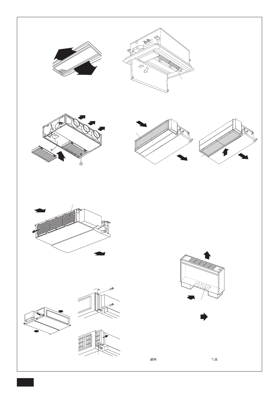
[Fig. A]
A
A
A
A
<PLFY-P-VLMD-A>
<PDFY-P-VM-A>
<PEFY-P-VML-A>
<PEFY-P-VMM-A>
<PEFY-P-VMH-A>
<PFFY-P-VLEM-A, VLRM-A>
A
: Filter
Filter
Filtre
Filtro
Filtro
Filter
Filtro
º›ÏÙÚÔ
Фильтр
Filtre
: Air Flow
Luftstrom
Flux d’air
Flujo de aire
Flusso d’aria
Luchtstroom
Fluxo de Ar
ƒÔ‹ ·¤Ú·
Воздушный поток
Hava Ak›m›
A
A
In case of rear inlet
In case of bottom inlet
7
G
B
D
F
I
N
L
E
P
G
R
R
U
T
R
1. Safety precautions
s
Before operating the unit, make sure you read all the “Safety
precautions”.
s
“Safety precautions” lists important points about safety.
Please be sure to follow them.
Symbols used in the text
Warning:
Describes precautions that should be observed avoid the risk of injury or
death to the user.
Caution:
Describes precautions that should be observed to prevent damage to the
unit.
Symbols used in the illustrations
: Indicates an action that must be avoided.
: Indicates that important instructions must be followed.
: Indicates a part which must be grounded.
: Indicates that caution should be taken with rotating parts. (This symbol is
displayed on the main unit label.) <Color: yellow>
: Beware of electric shock. (This symbol is displayed on the main unit label.)
<Color: yellow>
Warning:
Carefully read the labels affixed to the main unit.
1.1. Installation
s
After you have read this manual, keep it and the Installation Manual in a
safe place for easy reference whenever a question arises. If the unit is
going to be operated by another person, make sure that this manual is
given to him or her.
Warning:
•
The unit should not be installed by the user. Ask the dealer or an author-
ized company to install the unit. If the unit is installed improperly, water
leakage, electric shock or fire may result.
•
Use only accessories authorized by Mitsubishi Electric and ask your
dealer or an authorized company to install them. If accessories are in-
stalled improperly, water leakage, electric shock or fire may result.
•
The Installation Manual details the suggested installation method. Any
structural alteration necessary for installation must comply with local
building code requirements.
•
Never repair the unit or transfer it to another site by yourself. If repair is
performed improperly, water leakage, electric shock or fire may result. If
you need to have the unit repaired or moved, consult your dealer.
•
The appliance is not intended for use by young children or infirm per-
sons without supervision.
•
Young children should be supervised to ensure that they do not play
with the appliance.
1) Outdoor unit
Warning:
•
The outdoor unit must be installed on a stable, level surface, in a place
where there is no accumulation of snow, leaves or rubbish.
•
Do not stand on, or place any items on the unit. You may fall down or the
item may fall, causing injury.
Caution:
The outdoor unit should be installed in a location where air and noise emit-
ted by the unit will not disturb the neighbours.
2) Indoor unit
Warning:
The indoor unit should be securely installed. If the unit is loosely mounted, it
may fall, causing injury.
3) Remote controller
Warning:
The remote controller should be installed in such a way that children cannot
play with it.
4) Drain hose
Caution:
Make sure that the drain hose is installed so that drainage can go ahead
smoothly. Incorrect installation may result in water leakage, causing dam-
age to furniture.
5) Power line, fuse or circuit breaker
Warning:
•
Make sure that the unit is powered by a dedicated supply. Other appli-
ances connected to the same supply could cause an overload.
•
Make sure that there is a main power switch.
•
Be sure to adhere to the unit’s voltage and fuse or circuit breaker ratings.
Never use a piece of wire or a fuse with a higher rating than the one
specified.
6) Grounding
Caution:
•
The unit must be properly grounded. Never connect the grounding wire
to a gas pipe, water pipe, lightning conductor or telephone grounding
wire. If the unit is not grounded properly, electric shock may result.
•
Check frequently that the ground wire from the outdoor unit is properly
connected to both the unit’s ground terminal and the grounding elec-
trode.
1.2. During operation
Caution:
•
Do not use any sharp object to push the buttons, as this may damage the
remote controller.
•
Do not twist or tug on the remote controller cord as this may damage the
remote controller and cause malfunction.
•
Never remove the upper case of the remote controller. It is dangerous to
remove the upper case of the remote controller and touch the printed
circuit boards inside. Doing so can result in fire and failure.
•
Never wipe the remote controller with benzene, thinner, chemical rags,
etc. Doing so can result in discoloration and failure. To remove heavy
stains, soak a cloth in neutral detergent mixed with water, wring it out
thoroughly, wipe the stains off, and wipe again with a dry cloth.
•
Never block or cover the indoor or outdoor unit’s intakes or outlets. Tall
items of furniture underneath the indoor unit, or bulky items such as
large boxes placed close to the outdoor unit will reduce the unit’s effi-
ciency.
Warning:
•
Do not splash water over the unit and do not touch the unit with wet
hands. An electric shock may result.
•
Do not spray combustible gas close to the unit. Fire may result.
•
Do not place a gas heater or any other open-flame appliance where it will
be exposed to the air discharged from the unit. Incomplete combustion
may result.
Contents
1. Safety precautions ...................................................................................... 7
1.1. Installation ................................................................................. 7
1.2. During operation ........................................................................ 7
1.3. Disposing of the unit .................................................................. 8
2. Names and functions of various parts ........................................................ 8
3. How to operate ........................................................................................... 8
3.1. ON/OFF ..................................................................................... 8
3.2. Selecting operation .................................................................... 8
3.3. Room temperature adjustment .................................................. 9
3.4. Fan speed adjustment ............................................................... 9
3.5. Adjustment of up/down airflow direction .................................... 9
3.6. Time setting ............................................................................... 9
3.7. Timer setting ............................................................................ 10
3.8. Ventilation ................................................................................ 10
3.9. Others ...................................................................................... 10
4. The smart way to use ............................................................................... 10
5. Caring for the machine ............................................................................. 11
6. Troubleshooting ......................................................................................... 11
7. Installation, transferring works, and checking ........................................... 12
8. Specifications ............................................................................................ 12
8
G
B
D
F
I
N
L
E
P
G
R
R
U
T
R
Warning:
•
Do not remove the front panel or the fan guard from the outdoor unit
when it is running. You could be injured if you touch rotating, hot or high-
voltage parts.
•
Never insert fingers, sticks etc. into the intakes or outlets, otherwise in-
jury may result, since the fan inside the unit rotates at high speed. Exer-
cise particular care when children are present.
•
If you detect odd smells, stop using the unit, turn off the power switch
and consult your dealer. Otherwise, a breakdown, electric shock or fire
may result.
•
When you notice exceptionally abnormal noise or vibration, stop opera-
tion, turn off the power switch, and contact your dealer.
•
Do not over-cool. The most suitable inside temperature is one that is
within 5
°
C of the outside temperature.
•
Do not leave handicapped people or infants sitting or standing in the path
of the airflow from the air-conditioner. This could cause health problems.
Caution:
•
Do not direct the airflow at plants or caged pets.
•
Ventilate the room frequently. If the unit is operated continuously in a
closed room for a long period of time, the air will become stale.
In case of failure
Warning:
•
Never remodel the air conditioner. Consult your dealer for any repair serv-
ice. Improper repair work can result in water leakage, electric shock, fire, etc.
•
If the remote controller displays an error indication, the air conditioner
does not run, or there is any abnormality, stop operation and contact
your dealer. Leaving the unit as it is under such conditions can result in
fire or failure.
•
If the power breaker is frequently activated, get in touch with your dealer.
Leaving it as it is can result in fire or failure.
•
If the refrigeration gas blows out or leaks, stop the operation of the air
conditioner, thoroughly ventilate the room, and contact your dealer. Leav-
ing the unit as it is can result in accidents due to oxygen deficiency.
When the air conditioner is not to be used for a long
time
•
If the air conditioner is not to be used for a long time due to a seasonal
change, etc., run it for 4 - 5 hours with the air blowing until the inside is
completely dry. Failing to do so can result in the growth of unhygienic,
unhealthy mold in scattered areas throughout the room.
•
When it is not to be used for an extended time, keep the [power supply]
turned OFF.
If the power supply is kept on, several watts or several tens of watts will
be wasted. Also, the accumulation of dust, etc., can result in fire.
•
Keep the power switched ON for more than 12 hours before starting op-
eration. Do not turn the power supply OFF during seasons of heavy use.
Doing so can result in failure.
1.3. Disposing of the unit
Warning:
When you need to dispose of the unit, consult your dealer. If pipes are re-
moved incorrectly, refrigerant (fluorocarbon gas) may blow out and come
into contact with your skin, causing injury. Releasing refrigerant into the
atmosphere also damages the environment.
2. Names and functions of various parts
Attachment and detachment of filter
[Fig. A] (P.6)
TIMER SET
PAR-20MAA
ON/OFF
CENTRALLY CONTROLLED
ERROR CODE
CLOCK
ON OFF
˚C
CHECK
CHECK MODE
FILTER
TEST RUN
FUNCTION
˚C
1Hr.
NOT AVAILABLE
STAND BY
DEFROST
FILTER
CHECK TEST
TEMP.
3
2
E
C
A
1
6 8 7
4
B
3. How to operate
Before starting operation
•
Start running after the “H0” display has disappeared. The “H0” display briefly
appears on the room temperature display (max. 3 minutes) when the power is
turned on and after a power failure. This does not indicate any failure of the air
conditioner.
•
The operation modes of the indoor units’ cooling operation, dry operation, and
heating operation are different from those of the outdoor units.
When the operation is started with cooling/dry (heating) and other indoor units
connected to the counterpart outdoor units are already running in the same
operation mode, the remote control displays “
” or “ ” (“
”) mode. However,
the operation comes to stop, and you cannot get a desired mode. When this
occurs, you will be notified by the “
” or “ ” (“
”) display that flashes in the
liquid crystal display of the remote controller. Set to the operation mode of
other indoor unit by the operation switch button.
The above does not apply to the models that simultaneously run both the cool-
ing operation and heating operation.
•
The outdoor units stop when all the indoor units connected to the counterpart
outdoor units stop.
•
During heating operation, even if the indoor unit is set to operation while the
outdoor unit is in defrosting operation, operation starts after the defrosting op-
eration of the outdoor unit has ended.
3.1. ON/OFF
Start an operation
1. Press the B
B
B
B
B
[ON/OFF] button
Operation lamp V lights up and operation starts.
Stop an operation
1. Press the B
B
B
B
B
[ON/OFF] button again
Operation lamp goes off and operation stops.
•
Once the buttons have been set, pressing of the [ON/OFF] button only can
repeat the same operation thereafter.
•
During operation, the operation lamp above the [ON/OFF] button lights up.
Caution:
Even if the operation button is pressed immediately after the operation is
once stopped, operation is not restarted for about 3 minutes. This function
protects the machine. It automatically starts operation after the lapse of ap-
proximately 3 minutes.
3.2. Selecting operation
When selecting operation
1. Press the 3
3
3
3
3
[selecting operation] button
Consecutive press of the selecting operation button switches the operation
over to E “
,” “ ,” “
,” (“
”), and (“
”). For the contents of operation,
check the display.
For cooling
Press the 3
3
3
3
3
[selecting operation] button and bring up the “
” display.
For dry
Press the 3
3
3
3
3
[selecting operation] button and bring up the “ ” display.
•
The indoor fan turns to the low-speed operation, disabling the change of fan
speed.
•
Dry operation cannot be carried out at a room temperature of less than 18
°C.
For fan
Press the 3
3
3
3
3
[selecting operation] button and bring up the “
” display.
•
The fan operation functions to circulate the air in the room.
•
The temperature of the room cannot be set by fan operation.
Caution:
•
In removing the filter, precautions must be taken to protect your eyes
from dust. Also, if you have to climb up on a stool to do the job, be careful
not to fall.
•
Turn off the power supply when the filter is changed.

9
G
B
D
F
I
N
L
E
P
G
R
R
U
T
R
[PLFY-PVLMD, PDFY-P20~80VM series]
Fan speed : 4 stages
Display:
(Low)
→
(Mid2)
→
(Mid1)
→
(High)
[PEFY-P-VML, PEFY-P20~80-VMM series]
Fan speed : 3 stages
Display:
(Low)
→
(Mid)
→
(High)
3.5. Adjustment of up/down airflow direction
To change the up/down airflow direction
Every time the 7
7
7
7
7
[up/down airflow direction] button is pressed, the direction
of the airflow changes.
*1 • It automatically returns to the “2 0
°” when one hour passes.
• The “1 Hr.” is displayed on the remote controller (It is disappeared when one
hour passes.)
•
This function is not available according to the models.
•
In the following cases, it is different for the display and the unit.
1. “DEFROST” or “STAND BY” is displayed
2. Just starting in heating mode
3. Thermostat OFF in heating mode
PFFY-P-VLEM
While pulling the blowout grill out toward you, raise the rear, remove it, change the
direction, and set it in place.
Caution:
Avoid putting your hand into the air outlet of the indoor unit any more than
necessary during operation. If you get your hands caught in the metal parts
when adjusting the airflow-direction-adjustment board and blowout grill, or
nip them in the autovane, there is a risk of injury and failure.
3.6. Time setting
•
Set the current time after turning ON the power of the air conditioner or after
restoration from a power failure.
•
It can be set regardless of the operation of the indoor unit.
•
During the time operation, the time-setting button becomes void, disabling time
setting.
1. Press the 4
4
4
4
4
[time selection] button and bring up the A
A
A
A
A
“current time”
display
•
Every time it is pressed, the display changes.
Caution:
When the current time is not yet set, the “CLOCK (current time)” display
flashes, disabling the setting of timer operation.
Caution:
Never expose your body directly to cool air for a long time. Excessive expo-
sure to cool air is bad for your health, and should therefore be avoided.
Dry operation
The dry is a microcomputer-controlled dehumidifying operation which controls ex-
cessive air-cooling according to the room temperature of your choice. (Not usable
for heating.)
1. Until reaching room temperature of your choice
The compressor and indoor fan function is linked motion according to the change
of the room temperature and automatically repeat ON/OFF.
2. When reaching room temperature of your choice
Both the compressor and indoor fan stop.
When stop continues for 10 minutes, the compressor and indoor fan are oper-
ated for 3 minutes to keep the humidity low.
For heating
Press the 3
3
3
3
3
[selecting operation] button to bring up the “
” display.
Regarding displays during heating operation “DEFROST”
Displayed only during the defrosting operation.
“STAND BY”
Displayed from the start of heating operation until the moment warm air blows out.
Caution:
•
When the air conditioner is used together with burners, thoroughly ven-
tilate the area. Insufficient ventilation can result in accidents due to oxy-
gen deficiency.
•
Never place a burner at a place where it is exposed to the airflow from the
air conditioner.
Doing so can result in imperfect combustion of the burner.
•
The microcomputer functions in the following cases:
•
Air does not blow out when heating starts.
- To prevent any cool air from escaping, the indoor fan is gradually switched in
sequence from faint airflow/weak airflow/set airflow according to the tem-
perature rise of the blown out air. Wait a moment until the airflow comes out
naturally.
•
The fan is not moving at the set speed.
- In some models, the system switches over to faint airflow when the tempera-
ture of the room reaches the set temperature. In other cases, it stops to
prevent any cool air from escaping during the defrosting operation.
•
Air flows out even if operation is stopped.
- Approximately 1 minute after the stop of operation, the indoor fan sometimes
rotates to eliminate extra heat generated by the electric heater, etc. The fan
speed comes to low or high.
3.3. Room temperature adjustment
To change room temperature
Press the 1
1
1
1
1
[room temperature adjustment] button and set the room tem-
perature of your choice.
Pressing
or
once changes the setting by 1
°C.
If the pressing is continued, the setting continues to change by 1
°C.
•
Indoor temperature can be set within the following range.
Cooling/dry: 19 - 30
°C
Heating:
17 - 28
°C
•
It is impossible to set the room temperature by the air-blow operation.
*
The range of room temperature display is 8 - 39
°C. Outside this range, the
display flashes either 8 - 39
°C to inform you if the room temperature is lower or
higher than the displayed temperature.
3.4. Fan speed adjustment
To change fan speed
Every time you press the 6 [fan speed] button once, it switches from the low-
speed to high-speed settings successively.
In the electronics dry operation, the indoor fan automatically turns to low-speed
operation. Switching of fan speed is impossible. (Only the display on the remote
controller changes.)
*
Every time the fan speed adjustment button is once pressed, the fan speed is
changed.
[PEFY-P200·250VMH]
Fan speed : 1 stage
Display:
(High)
PEFY-P-VM, PEFY-P40~140VMH, PFFY-P-VLEM, PFFY-P-VLRM
PDFY-P100·125VM, PEFY-P100~140-VMM series
Fan speed : 2 stages
Display:
(Low)
→
(High)
2
2
Cooling
Dry
Fan
Display
Initial setting
1
1
–
5
5
*1
Heating
4
4
–
3
3
–
1
Swing
2
0
°
3
45
°
4
60
°
5
85
°
CLOCK
“current
time”
(no display)
“timer end
time”
OFF
“timer start
time”
ON
Fan speed
High/Mid1/
Mid2/Low
High
Mid1/Mid2/Low
Can not Change
Mode
Heating/Fan
Cooling
Dry
10
G
B
D
F
I
N
L
E
P
G
R
R
U
T
R
TIMER SET
PAR-20MAA
ON/OFF
CENTRALLY CONTROLLED
ERROR CODE
CLOCK
ON OFF
˚C
CHECK
CHECK MODE
FILTER
TEST RUN
FUNCTION
˚C
1Hr.
NOT AVAILABLE
STAND BY
DEFROST
FILTER
CHECK TEST
TEMP.
3
2
E
C
A
1
6 8 7
4
B
2. Set the current time by pressing the 4
4
4
4
4
or
button
•
The time cannot be set while the C “timer on” is displayed.
•
While the A “CLOCK” time is displayed, press the time setting 4
/
buttons and set the time.
•
The setting advances one minute every time the 4
button is pressed
once, and retrogresses one minute every time the 4
button is pressed
once.
When respective 4
/
buttons are pressed continuously, the time
display goes fast forward. It advances in the order of 1 minute unit - 10 minute
unit - one hour unit.
•
About 10 seconds after the button operation has been completed, the C “cur-
rent time” and A “CLOCK” displays disappear.
Caution:
•
Remote controller is equipped with a simplified clock with a precision of
about + or - one minute per month.
•
The time must be readjusted (reset) every time the air conditioner is sub-
jected to a power stop of the air conditioner or a power failure.
3.7. Timer setting
•
If the timer is set, the unit starts (stops) at the set time, and the time mode is
terminated.
•
When you wish to confirm the starting and ending time, press the 4 [time
selection] button while C “
” is displayed.
Function of timer
On-timer
Set the on-timer for the time the working day begins in your company.
When the set start time arrives, the air conditioner starts operation.
Off-timer
Use the off-timer as a reminder to turn off the air conditioner. When the set end-
work time arrives, the air conditioner stops operation.
There are three methods for using the timer.
1. ON/OFF Timer
When setting both starting and ending time
2. On-timer
When only setting the starting time
(Ending time is set to “ - - : - - ”)
3. Off-timer
When only setting the ending time
(Starting time is set to “ - - : - - ”)
4. The smart way to use
Even minimal steps to care for your air conditioner can help make its use far
more effective in terms of air-conditioning effect, electricity charges, etc.
Set the right room temperature
•
In cooling operation, a temperature difference of about 5
°C between indoors
and outdoors is optimum.
•
If the room temperature is raised by 1
°C during air-cooling operation, about
10 % electric power can be saved.
•
Excessive cooling is bad for health. It also results in the waste of electric power.
Clean the filter thoroughly
•
If the screen of the air filter becomes clogged, the airflow and air-conditioning
effect can be significantly reduced.
Further, if the condition is left unattended, failure can result. It is particularly
important to clean the filter at the beginning of the cooling and heating sea-
sons. (When profuse dust and dirt have accumulated, clean the filter thoroughly.)
ON
OFF
ON
OFF
Display example of timer setting
The example shows a timer set for operation start at 8:00 and end at 17:00.
1. Press the 2
2
2
2
2
[timer/continuous] button and bring up the C
C
C
C
C
no display
2. Press the 4
4
4
4
4
[time selection] button and bring up the A
A
A
A
A
“Timer start time”
display
3. Press the 4
4
4
4
4
(
) button of the 4
4
4
4
4
[time selection] and set the
starting time
When using it as an off-timer, set the starting time to “ - - : - - ”.
The “ - - : - - ” is displayed next to 23:50.
4. Press the 4
4
4
4
4
[time selection] button and bring up the A
A
A
A
A
“Timer end time”
display
5. Press the 4
4
4
4
4
(
) button of the [time switch] and set the ending
time
When using it as an on-timer, set the ending time to “ - - : - - ”.
The “ - - : - - ” is displayed next to 23:50.
6. Press the 2
2
2
2
2
[timer/continuous] button and bring up the C
C
C
C
C
“
” display
Bringing up the C “
” display completes the setting.
Every time the 4
(
) button of the 4 [timer selection] is pressed once,
it advances (or retrogresses) by 10 minutes.
If the button is pressed continuously, it advances (or retrogresses) continuously.
First set the hour digit and then set the minute digit.
When the ON/OFF timer mode is set, you can run (on-timer) or stop (off-timer)
operation by pressing the B [ON/OFF] button even when there is remaining time.
Release
Press the 2
2
2
2
2
[timer/continuous] button and disappear the “
” display.
3.8. Ventilation
•
The ventilatior (OA processing unit or LOSSNAY) is automatically oper-
ated with the indoor unit when it interlocks to the indoor unit.
•
Press the 8
8
8
8
8
[Ventilation] button when indoor unit stops, only the ventila-
tor is operated.
•
8
8
8
8
8
[Ventilation] button is once pressed, the fan speed is changed.
•
The fan of indoor unit runs even when only the ventilator is operated
according to the model of indoor unit and ventilator occasionally.
3.9. Others
CENTRALLY CONTROLLED
: Displayed when control is executed by a separately
sold centralized control unit, etc.
STAND BY
DEFROST
: Displayed from the start of heating operation until the
moment warm air blows out.
CHECK
: This displays indication when some abnormality oc-
curs in the unit.
NOT AVAILABLE
: When a button is pressed for any function which the
indoor unit cannot perform, this display flashes con-
currently with the display of that function.
: In the system in which the [Sensor] display is indi-
cated as the “remote controller”, room temperature
measurement is performed by the room temperature
sensor built into the remote controller. Therefore, pay
attention to the following:
FILTER
: Displayed when it is time to clean the filter.
Press the A [Filter] button twice, then the display is
disappeared.

11
G
B
D
F
I
N
L
E
P
G
R
R
U
T
R
5. Caring for the machine
Before care-taking, turn the power supply OFF.
Caution:
•
Before you start cleaning, stop operation and turn OFF the power supply.
Remember that the fan is rotating inside at high speed, posing a serious
risk of injury.
•
Indoor units are equipped with filters to remove the dust of sucked-in air.
Clean the filters using the methods shown in the following sketches. (The
standard filter should normally be cleaned once a week, and the long-life
filter at the beginning of each season.)
•
The life of the filter depends on where the unit is installed and how it is
operated.
How to clean
•
Clear dust away lightly or clean it up with a vacuum cleaner. In the case of
severe staining, wash the filter in lukewarm water mixed with dissolved neutral
detergent or water, and then rinse off the detergent completely. After washing,
dry it and fix it back into place.
Caution:
•
Do not dry the filter by exposing it to direct sunlight or warming it using
fire, etc. Doing so can result in the deformation of the filter.
•
Washing it in hot water (more than 50
°
C) can also result in deformation.
Caution:
Never pour water or flammable sprays onto the air conditioner. Cleaning using
these methods can result in the failure of the air conditioner, electric shock,
or fire.
6. Troubleshooting
Before you ask for repair service, check the following points:
State of Machine
It does not run.
Air flows out but it does
not cool enough or heat
enough.
Cool air or warm air
does not come out.
It runs briefly, but soon
stops.
The sound of the ex-
haust and rotation of
the motor can still be
heard after stop of run-
ning.
The sound of the ex-
haust and the rotation
of the motor can be
heard intermittently af-
ter stop of running.
Warm air comes out in-
termittently when the
thermostat is OFF or
during fan operation.
Troubleshooting
Press the [ON/OFF] button after power restoration.
Turn the power supply ON.
Replace fuse.
Put in the earth leakage breaker.
After checking the set temperature and inlet temperature
on the liquid crystal display, refer to [Room temperature
adjustment], and operate the adjustment button.
Clean up the filter.
(Refer to [Caring for the machine].)
Remove.
Close.
Wait for a while.
(To protect the compressor, a 3-minute restart-preventing
circuit is built into the indoor unit. Therefore, there are occa-
sions sometimes when the compressor does not start run-
ning immediately. There are cases when it does not run for
as long as 3 minutes.)
Wait for a while.
(Heating operation starts after ending defrosting operation.)
Rerun after removal
Rerun after cleaning the filter. (Refer to [Caring for the ma-
chine].)
Wait for 3 minutes.
It soon stops. (If the noise occurs more than 2-3 times in an
hour, ask for repair service.)
It soon stops. (If the room temperature rises uncomfortably
high in a small room, stop operation.)
Cause
Power failure
The power supply is turned OFF.
The fuse in the power supply is gone.
The earth leakage breaker is gone.
Improper temperature adjustment
The filter is filled with dust and dirt.
There are some obstacles at the air inlet and outlet of
the indoor and outdoor units.
Windows and doors are open.
The restart-preventing circuit is in operation for 3 min-
utes.
Indoor unit operation was started anew during the heat-
ing and defrosting operation.
There are some obstacles at the air inlet and outlet of
the indoor and outdoor units.
The filter is filled with dust and dirt.
When other indoor units are engaged in cooling opera-
tion, the machine stops after running a drain-up mecha-
nism for 3 minutes when air-cooling operation is
stopped.
When other indoor units are engaged in cooling opera-
tion, drained water is brought in. If the drain water is
collected, the drain-up mechanism initiates a draining
operation.
When other indoor units are engaged in heating op-
eration, the control valves are opened and closed from
time to time to maintain the stability of the system.
Remote Controller
“'” display is not lit up
No display appears even
when the [ON/OFF] but-
ton is pressed.
The liquid crystal display
shows that it is in the
state of operation.
The liquid crystal display
shows that it is in opera-
tion.
The “check” and check
code flashes on the liquid
crystal display.
All lights are out except
the powered display of
“'”.
All lights are out except
the powered display of
“'”.
The liquid crystal display
shows that it is in the
state of operation.
•
If operation stops due to a power failure, the [restart-preventing circuit at power failure] operates and disables unit operation even after power restoration. In this case,
press the [ON/OFF] button again and start operation.
If malfunctions persist after you have checked the above, turn the power supply OFF and contact your dealer with information about the product name, the nature of the
malfunction, etc. If the display of “[check]” and (4 digit) check code flashes, tell the dealer contents of the display (check code). Never attempt to repair by yourself.
The following symptoms are not air conditioner failures:
•
The air blown out from the air conditioner can sometimes give off odors. This is due to cigarette smoke contained in the air of the room, the smell of cosmetics, the walls,
furniture, etc., absorbed in the air conditioner.
•
A hissing noise can be heard immediately after the air conditioner is started or stopped. This is the sound of the refrigeration flowing inside the air conditioner. This is
normal.
•
The air conditioner sometimes snaps or clicks at the beginning or end of cooling/heating operation. This is the sound of friction on the front panel and other sections due
to expansion and contraction caused by temperature change. This is normal.
Prevent intrusion of heat during air-cooling
•
To prevent the intrusion of heat during cooling operation, provide a curtain or a
blind on the window to block out direct sunlight. Also, do not open the entrance
or exit except in cases of dire necessity.
Carry out ventilation sometimes
•
Since the air periodically gets dirty in a room that is kept closed for a long time,
ventilation is sometimes necessary. When gas appliances are used together
with the air conditioner, special precautions must be taken. If the “LOSSNAY”
ventilation unit developed by our company is used, you can perform ventilation
with less waste. For details on this unit, consult with your dealer.
12
G
B
D
F
I
N
L
E
P
G
R
R
U
T
R
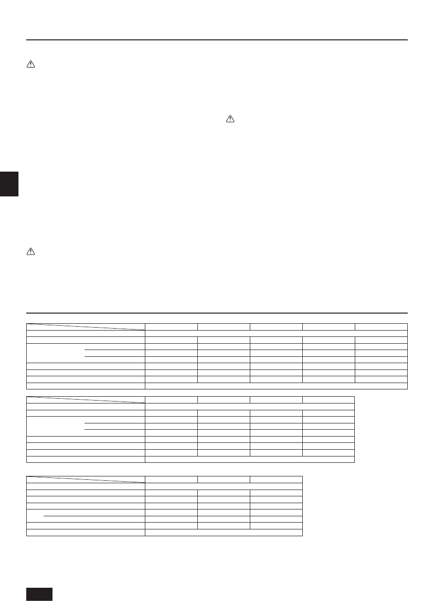
Power source
Cooling capacity*1 / Heating capacity*1
kW
Height
mm
Dimension*2
Width
mm
Depth
mm
Net weight
kg
Fan Airflow rate (Low-Middle2-Middle1-High) m
3
/min
Noise level (Low-Middle2-Middle1-High)
dB(A)
Filter
P25VML-A
2.8/3.2
225/720/550
18
5.4-6.5-7.9
5
29-33-36
~220-240V 50/60Hz
PEFY-P-VML-A series
Power source
Cooling capacity*1 / Heating capacity*1
kW
Dimension
Height / Width / Depth
mm
Net weight
kg
Fan
Airflow rate (Low-Middle-High)
m
3
/min
External static pressure
Pa
Noise level (Low-Middle-High)
dB(A)
Filter
P32VML-A
3.6/4.0
225/720/550
18
6.0-7.5-9.5
5
30-35-40
P20VML-A
2.2/2.5
225/720/550
18
5.4-6.5-7.9
5
29-33-36
Item
Model
7. Installation, transferring works, and checking
Regarding place for installation
Consult with your dealer for details on installation and transferring the installation.
Caution:
Never install the air conditioner where there is a risk of leakage of flammable
gas.
If gas leaks and accumulates around the unit, fire can result.
Never install the air conditioner at the following place:
•
where there is a lot of machine oil
•
near the ocean and beach areas where there is salt air.
•
where humidity is high
•
where there are hot springs nearby
•
where there is sulphurous gas
•
where there is a high-frequency processing machinery (a high-frequency welder,
etc.)
•
where acid solution is frequently used
•
where special sprays are frequently used
•
Install the indoor unit horizontally. Otherwise, water leakage can result.
•
Take sufficient measures against noise when installing the air conditioners at
hospitals or communication-related businesses.
If the air conditioner is used in any of the above-mentioned environments, frequent
operational failure can be expected. It is advisable to avoid these types of installa-
tion sites.
For further details, consult with your dealer.
Regarding electrical work
Caution:
•
The electrical work must be undertaken by a person who is qualified as
an electrical engineer according to the [technical standard respecting
electrical installation], [internal wiring rules], and the installation instruc-
tion manual with the absolute use of exclusive circuits. The use of other
products with the power source can result in burnt-out beakers and fuses.
•
Never connect the grounding wire to a gas pipe, water pipe, arrester, or
telephone grounding wire. For details, consult with your dealer.
•
In some types of installation sites, the installation of an earth leakage
breaker is mandatory. For details, consult with your dealer.
Regarding transfer of installation
•
When removing and reinstalling the air conditioner when you enlarge your
home, remodel, or move, consult with your dealer in advance to ascertain the
cost of the professional engineering work required for transferring the installa-
tion.
Caution:
When moving or reinstalling the air conditioner, consult with your dealer.
Defective installation can result in electric shock, fire, etc.
Regarding noise
•
In installing work, choose a place that can fully bear the weight of the air con-
ditioner, and where noise and vibration can be reduced.
•
Choose a place where cool or warm air and noise from the outdoor air outlet of
the air conditioner does not inconvenience the neighbors.
•
If any alien object is placed near the outdoor air outlet of the air conditioner,
decreased performance and increased noise can result. Avoid placing any
obstacles adjacent to the air outlet.
•
If the air conditioner produces any abnormal sound, consult with your dealer.
Maintenance and inspection
•
If the air conditioner is used throughout several seasons, the insides can get
dirty, reducing the performance.
Depending upon the conditions of usage, foul odors can be generated and
drainage can deteriorate due to dust and dirt, etc.
P32VLMD-A
3.6/4.0
338 (8)
768 (1,060)
606 (670)
25 (7)
6.5-7.0-7.8-8.5
29-31-34-36
P20VLMD-A
2.2/2.5
338 (8)
768 (1,060)
606 (670)
24 (7)
6.0-6.5-7.3-8.0
28-30-33-35
P50VLMD-A
5.6/6.3
338 (8)
1,008 (1,300)
606 (670)
35 (8)
10.0-11.0-12.0-13.0
32-34-36-38
8. Specifications
Item
Model
P25VLMD-A
2.8/3.2
338 (8)
768 (1,060)
606 (670)
24 (7)
6.0-6.5-7.3-8.0
28-30-33-35
P40VLMD-A
4.5/5.0
338 (8)
1,008 (1,300)
606 (670)
33.5 (8)
9.0-10.5-11.5-12.5
29-32-34-36
~220-240V 50Hz
PLFY-P-VLMD-A series
Notes: *1 Cooling/Heating capacity indicates the maximum value at operation under the following condition.
Cooling: Indoor: 27
°C DB/19 °C WB
Outdoor: 35
°C DB
Heating: Indoor: 20
°C DB
Outdoor: 7
°C DB/6 °C WB
*2 The figure in ( ) indicates panel’s.
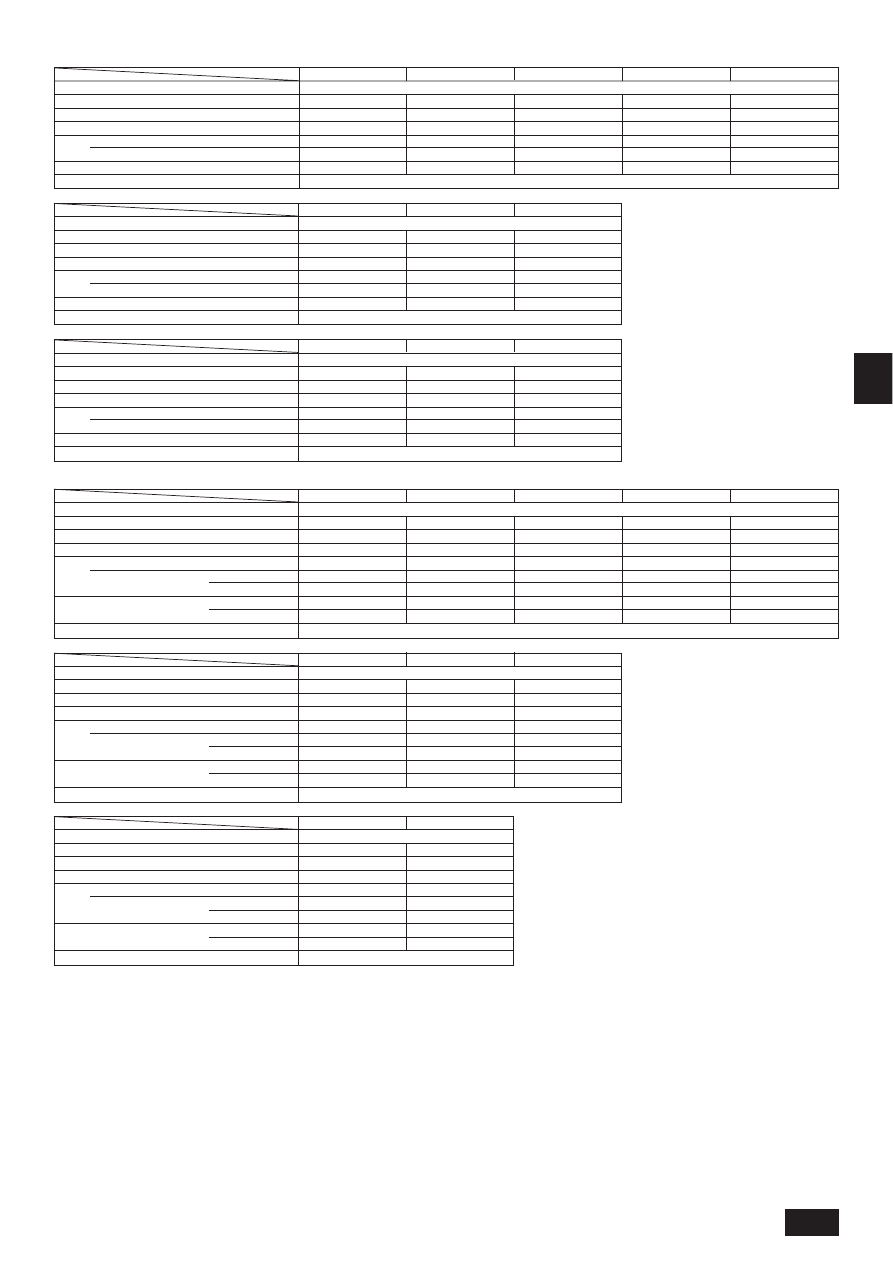
P125VLMD-A
14.0/16.0
338 (8)
1,708 (2,000)
606 (670)
56 (11.5)
24.0-27.0-30.0-33.0
40-42-44-46
Power source
Cooling capacity*1 / Heating capacity*1
kW
Height
mm
Dimension*2
Width
mm
Depth
mm
Net weight
kg
Fan Airflow rate (Low-Middle2-Middle1-High) m
3
/min
Noise level (Low-Middle2-Middle1-High)
dB(A)
Filter
P80VLMD-A
9.0/10.0
338 (8)
1,358 (1,650)
606 (670)
39 (10)
15.0-17.0-19.0-21.0
36-38-41-43
P100VLMD-A
11.2/12.5
338 (8)
1,708 (2,000)
606 (670)
56 (11.5)
21.0-23.0-26.0-29.0
37-39-41-43
P63VLMD-A
7.1/8.0
338 (8)
1,358 (1,650)
606 (670)
39 (10)
13.0-14.0-16.0-18.0
32-34-37-39
Item
Model
~220-240V 50Hz
Long life filter
Long life filter
Standard filter
13
G
B
D
F
I
N
L
E
P
G
R
R
U
T
R
P250VMH-A
28.0/31.5
470/1,250/1,120
100
72.0
110/220
130/260
50
52
P200VMH-A
22.4/25.0
470/1,250/1,120
100
58.0
110/220
130/260
42
44
3N~380-415V 50/60Hz
P63VMH-A
7.1/8.0
380/750/900
45
13.5-19.0
50/100/200
100/150/200
32-38
36-41
P40VMH-A
4.5/5.0
380/750/900
44
10.0-14.0
50/100/200
100/150/200
27-34
31-37
P80VMH-A
9.0/10.0
380/1,000/900
50
18.0-25.0
50/100/200
100/150/200
35-41
38-43
Power source
Cooling capacity*1 / Heating capacity*1
kW
Dimension
Height / Width / Depth
mm
Net weight
kg
Airflow rate (Low-High)
m
3
/min
Fan
External static
Pa
220 V
pressure*3
230, 240 V
Noise level
dB(A)
220 V
(Low-High)
230, 240 V
Filter
Item
Model
P50VMH-A
5.6/6.3
380/750/900
44
10.0-14.0
50/100/200
100/150/200
27-34
31-37
P71VMH-A
8.0/9.0
380/1,000/900
50
15.5-22.0
50/100/200
100/150/200
32-39
35-41
~220-240V 50/60Hz
PEFY-P-VMH-A series
P140VMH-A
16.0/18.0
380/1,200/900
70
28.0-40.0
50/100/200
100/150/200
34-42
38-44
P100VMH-A
11.2/12.5
380/1,200/900
70
26.5-38.0
50/100/200
100/150/200
34-42
38-44
Power source
Cooling capacity*1 / Heating capacity*1
kW
Dimension
Height / Width / Depth
mm
Net weight
kg
Airflow rate (Low-High)
m
3
/min
Fan
External static
Pa
220 V
pressure*3
230, 240 V
Noise level
dB(A)
220 V
(Low-High)
230, 240 V
Filter
Item
Model
P125VMH-A
14.0/16.0
380/1,200/900
70
26.5-38.0
50/100/200
100/150/200
34-42
38-44
~220-240V 50/60Hz
Power source
Cooling capacity*1 / Heating capacity*1
kW
Dimension
Height / Width / Depth
mm
Net weight
kg
Airflow rate
m
3
/min
Fan
External static
Pa
380V
pressure*4
400, 415V
Noise level
dB(A)
380V
400, 415V
Filter
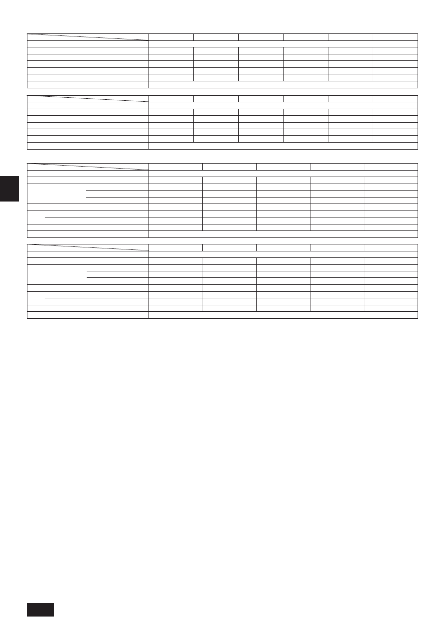
Item
Model
P32VMM-A
3.6/4.0
295/815/700
27
7.5-9.0-10.5
30/50/100
28-32-35
~220-240V 50Hz
P20VMM-A
2.2/2.5
295/815/700
27
6.0-7.2-8.5
30/50/100
27-30-32
P50VMM-A
5.6/6.3
295/935/700
33
12.0-14.5-17.0
30/50/100
31-35-38
Power source
Cooling capacity*1 / Heating capacity*1
kW
Dimension
Height / Width / Depth
mm
Net weight
kg
Airflow rate (Low-Middle-High)
m
3
/min
Fan
External static pressure*2
Pa
Noise level (Low-Middle-High)
dB(A)
Filter
Item
Model
P25VMM-A
2.8/3.2
295/815/700
27
6.0-7.2-8.5
30/50/100
27-30-32
P40VMM-A
4.5/5.0
295/935/700
33
10.0-12.0-14.0
30/50/100
31-34-37
PEFY-P-VMM-A series
P80VMM-A
9.0/10.0
295/1,175/700
42
14.5-18.0-21.0
30/50/100
32-36-39
P63VMM-A
7.1/8.0
295/1,175/700
42
13.5-16.2-19.0
30/50/100
31-35-38
Power source
Cooling capacity*1 / Heating capacity*1
kW
Dimension
Height / Width / Depth
mm
Net weight
kg
Airflow rate (Low-Middle-High)
m
3
/min
Fan
External static pressure*2
Pa
Noise level (Low-Middle-High)
dB(A)
Filter
Item
Model
P71VMM-A
8.0/9.0
295/1,175/700
42
14.5-18.0-21.0
30/50/100
32-36-39
P140VMM-A
16.0/18.0
325/1,715/740
70
29.5-42.0
50/130
42-45
P100VMM-A
11.2/12.5
325/1,415/740
62
23.0-33.0
50/130
40-44
Power source
Cooling capacity*1 / Heating capacity*1
kW
Dimension
Height / Width / Depth
mm
Net weight
kg
Airflow rate (Low-High)
m
3
/min
Fan
External static pressure*2
Pa
Noise level (Low-High)
dB(A)
Filter
Item
Model
P125VMM-A
~220-240V 50Hz
14.0/16.0
325/1,415/740
65
28.0-40.0
50/130
42-45
~220-240V 50Hz
Standard filter
Standard filter
Standard filter
Long life filter (option)
Long life filter (option)
Long life filter (option)
Notes: *1 Cooling/Heating capacity indicates the maximum value at operation under the following condition.
Cooling: Indoor: 27
°C DB/19 °C WB
Outdoor: 35
°C DB
Heating: Indoor: 20
°C DB
Outdoor: 7
°C DB/6 °C WB
*2 The external static pressure is set to 50 Pa at factory shipment.
*3 The external static pressure is set to 100 Pa (at 220 V)/150 Pa (at 230, 240 V) at factory shipment.
*4 The external static pressure is set to 220 Pa (at 380 V)/260 Pa (at 400, 415 V) at factory shipment.
14
G
B
D
F
I
N
L
E
P
G
R
R
U
T
R
P32VM-A
3.6/4.0
295 (58)
710 (790)
735 (600)
27 (5)
6.0-6.5-7.5-8.5
30/50/100
28-30-33-36
Power source
Cooling capacity*1/Heating capacity*1
kW
Height
mm
Dimension*2
Width
mm
Depth
mm
Net weight
kg
Fan
Airflow rate (Low-Middle2-Middle1-High) m
3
/min
External static pressure*3
Pa
Noise level (Low-Middle2-Middle1-High)*4 dB(A)
Filter
P25VM-A
2.8/3.2
295 (58)
710 (790)
735 (600)
25.5 (5)
6.0-6.5-7.5-8.5
30/50/100
28-30-33-36
~220-240V 50Hz / ~220V 60Hz
PDFY-P-VM-A series
P20VM-A
2.2/2.5
295 (58)
710 (790)
735 (600)
25.5 (5)
6.0-6.5-7.5-8.5
30/50/100
28-30-33-36
Item
Model
P40VM-A
4.5/5.0
295 (58)
960 (1,040)
735 (600)
32 (6)
10.0-11.0-12.5-14.0
30/50/100
34-36-37-39
P50VM-A
5.6/6.3
295 (58)
960 (1,040)
735 (600)
34 (6)
10.0-11.0-12.5-14.0
30/50/100
34-36-37-39
P80VM-A
9.0/10.0
295 (58)
1,160 (1,240)
735 (600)
39 (7)
14.5-16.5-18.5-21.0
30/50/100
34-37-40-42
Power source
Cooling capacity*1/Heating capacity*1
kW
Height
mm
Dimension*2
Width
mm
Depth
mm
Net weight
kg
Fan
Airflow rate (Low-Middle2-Middle1-High) m
3
/min
External static pressure*3
Pa
Noise level (Low-Middle2-Middle1-High)*4 dB(A)
Filter
P71VM-A
8.0/9.0
295 (58)
1,160 (1,240)
735 (600)
39 (7)
13.5-15.5-17.5-19.5
30/50/100
32-35-37-40
~220-240V 50Hz / ~220V 60Hz
P63VM-A
7.1/8.0
295 (58)
1,160 (1,240)
735 (600)
39 (7)
12.5-14.0-16.0-18.0
30/50/100
30-34-36-39
Item
Model
P100VM-A
11.2/12.5
335 (58)
1,510 (1,590)
775 (600)
52 (8.5)
19.5-28.0
50/100/130
34-42 <37-44>
P125VM-A
14.5/16.3
335 (58)
1,510 (1,590)
775 (600)
52 (8.5)
24.0-34.0
50/100/130
40-45 <42-46>
Notes: *1 Cooling/Heating capacity indicates the maximum value at operation under the following condition.
Cooling:Indoor: 27
°C DB/19 °C WB
Outdoor: 35
°C DB
Heating:Indoor: 20
°C DB
Outdoor: 7
°C DB/6 °C WB
*2 The figure in ( ) indicates panel’s.
*3 The external static pressure is set to 50 Pa at factory shipment.
*4 The figure in < > indicates noise level at 240 V/50 Hz.
Operation temperature
Cooling mode: 15
°C WB - 24 °C WB
Heatingmode: 15
°C DB - 27 °C DB
*5 The figures represent a 240 V/50 Hz unit measured at a point which is 1 m away from the front of the unit and at a height of 1 m from the floor.
The noise is approximately 1 dB(A) less for a 230 V unit and approximately 2 dB(A) less for a 220 V unit. The noise is approximately 3 dB(A) less when the
measurement point is 1.5 m away from the front of the unit and at a height of 1.5 m from the floor.
P32VLEM-A
3.6/4.0
630/1,170/220
25
7.0-9.0
35-40
P40VLEM-A
4.5/5.0
630/1,170/220
26
9.0-11.0
38-43
P25VLEM-A
2.8/3.2
630/1,050/220
23
5.5-6.5
34-40
P63VLEM-A
7.1/8.0
630/1,410/220
32
12.0-15.5
40-46
Power source
Cooling capacity*1 / Heating capacity*1
kW
Dimension
Height / Width / Depth
mm
Net weight
kg
Fan
Airflow rate (Low-High)
m
3
/min
Noise level (Low-High)*5
dB(A)
Filter
Item
Model
P50VLEM-A
5.6/6.3
630/1,410/220
30
12.0-14.0
38-43
~220-240V 50Hz / ~208V-230V 60Hz
PFFY-P-VLEM-A/PFFY-P-VLRM-A series
P20VLEM-A
2.2/2.5
630/1,050/220
23
5.5-6.5
34-40
P40VLRM-A
4.5/5.0
639/1,006/220
21
9.0-11.0
38-43
P32VLRM-A
3.6/4.0
639/1,006/220
20
7.0-9.0
35-40
~220-240V 50Hz / ~208V-230V 60Hz
P25VLRM-A
2.8/3.2
639/886/220
18.5
5.5-6.5
34-40
P63VLRM-A
7.1/8.0
639/1,246/220
27
12.0-15.5
40-46
Power source
Cooling capacity*1 / Heating capacity*1
kW
Dimension
Height / Width / Depth
mm
Net weight
kg
Fan
Airflow rate (Low-High)
m
3
/min
Noise level (Low-High)*5
dB(A)
Filter
Item
Model
P50VLRM-A
5.6/6.3
639/1,246/220
25
12.0-14.0
38-43
P20VLRM-A
2.2/2.5
639/886/220
18.5
5.5-6.5
34-40
Standard filter
Standard filter
Long life filter
Long life filter
Wyszukiwarka
Podobne podstrony:
IM PEFY P VMM A WT03199X02 2004
IM PEFY P15 63VMS1 L E KB79H130H03 GB 08 2009
IM PEFY P 20 140VMM E WT04197X01 08 2005
IM PEFY P40 250VMH E WT04198X02 GB 2005
IM PEFY P VML A
2001 08 28
bph pbk raport roczny 2001
2001 11 29
60 Rolle der Landeskunde im FSU
arkusz fizyka poziom s rok 2001 535
2001 październik Cztery pory roku kryteria
2001 06 30
IM 5 dyfuzja wyklad 03
Porty morskie i żegluga morska w Polsce w latach 1999 2001
121 307 POL ED02 2001
2001 12 29
2001 10 26
80 307 POL ED02 2001
A2 2001 petrol YES
więcej podobnych podstron