
Initial Print Date:09/02
Revision Date:
Subject
Page
New features of body structure . . . . . . . . . . . . . . . . . . . . . . . . . . . . . . .2
Frontal impact . . . . . . . . . . . . . . . . . . . . . . . . . . . . . . . . . . . . . . . . . . . .2
Side impact . . . . . . . . . . . . . . . . . . . . . . . . . . . . . . . . . . . . . . . . . . . . .3
Roll-over crash . . . . . . . . . . . . . . . . . . . . . . . . . . . . . . . . . . . . . . . . . . .4
Rigidity . . . . . . . . . . . . . . . . . . . . . . . . . . . . . . . . . . . . . . . . . . . . . . . . .5
Torsional rigidity . . . . . . . . . . . . . . . . . . . . . . . . . . . . . . . . . . . . . . . . . .5
Table of Contents
Body Shell
2
Body Shell
Bodyshell
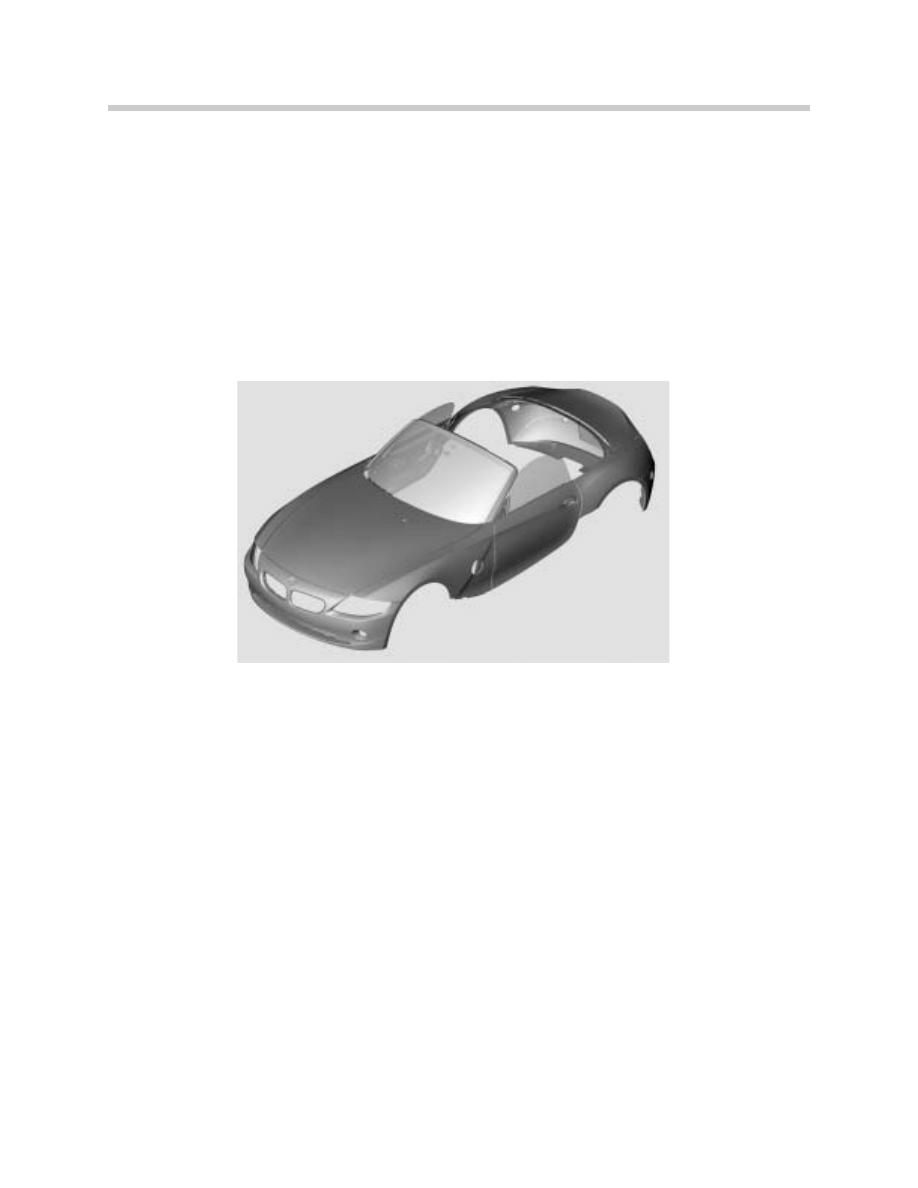
New features of body structure
The development process for the E85 bodyshell placed particular importance on crash
safety and ease of repair. The outside panel of the A pillar is a load-bearing component.
Between the outer and inner plates of the A-pillar there is a reinforcing tube. The rigidity of
the body if the car overturns has been improved by the reinforcement of the A-pillar and the
profile of the windscreen top rail.
Crash scenarios
Frontal impact
In the event of a frontal impact, the force is distributed as follows:
The force is passed from the aluminum-section bumper crossmembers via two deforma-
tion elements to the engine subframe members. From there, the forces are channeled into
the sills and the transmission tunnel ("Y" structure). The transmission tunnel is reinforced
by 4 tunnel side members.
Each of the sills is reinforced on the inside by 4 bulkheads. This also helps to prevent defor-
mation of the passenger compartment.
3
Body Shell
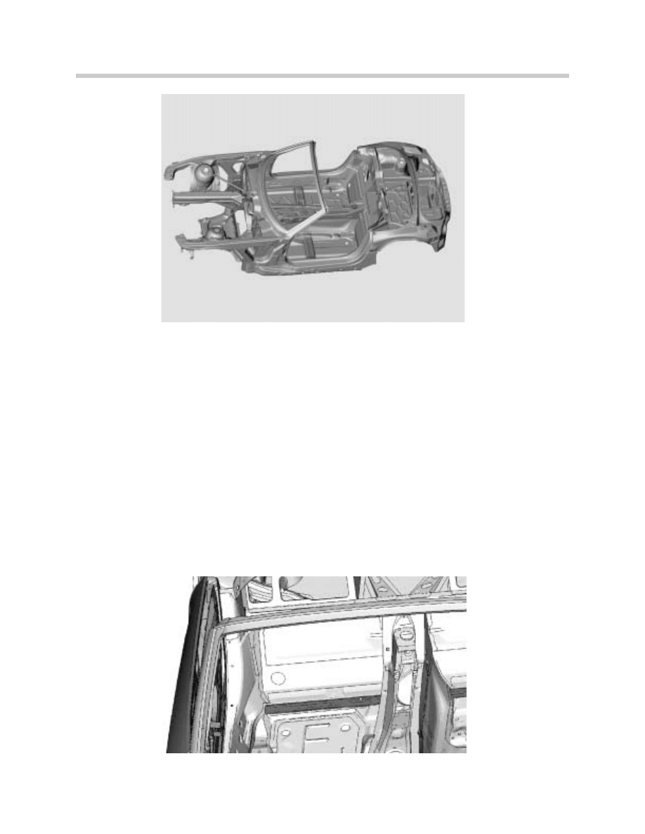
Side impact
In the event of a side impact, the forces are absorbed by a number of components:
•
At the front of the vehicle, the bulkhead absorbs the force.
•
In the door area, the force is channeled into the sills. The doors themselves are
strengthened by reinforcing plates. They absorb only a small amount of the force so that
they can still be opened after a crash.
•
In the area of the fuel filler pipe, the forces are channeled from the sill through the heel
plate and into the transmission tunnel. Lateral transfer in the tunnel is provided by the
rear thrust plate. This function was previously performed by a bridging plate.
Attachment of the thrust plate to the rear suspension has only a minimal effect on
rigidity. Therefore, in the event of a crash, very little energy is transmitted to the rear
suspension.
Rear impact
4
Body Shell
The distribution of forces in the event of a rear impact is as follows:
•
The force is passed from the bumper mountings via two deformation elements to the
rear body panel support. From there, the forces are channeled via longitudinal
members to the transmission tunnel. Relatively small forces can also be transferred by
the center brace. However, the primary purpose of the center brace and cross-braces
is to increase torsional rigidity. But since they do not have a predetermined fracture
point, they can also absorb relatively small compression forces.
Roll-over crash
If the car overturns, the forces are distributed as follows:
•
At the front, the forces are channeled via the A-pillars (with internal reinforcing tube) into
the bulkhead and the sills.
•
At the back, the force passes through the roll-over bars into the roll-over bar subframe
and from there to the side panels
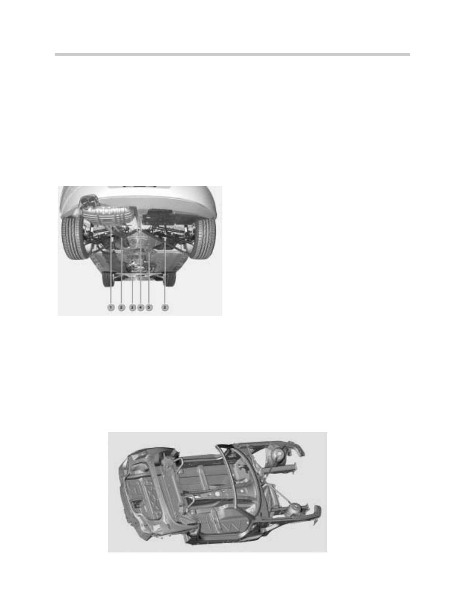
Rigidity
1. Brace Mounting
2. Right/Left Cross Braces
3. Front Thrust Plate
4. Center Brace
5. Rear Thrust Plate
5
Body Shell
Although the E85 is larger than its predecessor, the E36/7, the rigidity has been substan-
tially increased without increasing the weight.
The dynamic rigidity has been increased from approx. 17.5 Hz on the E36/7 to approx. 21
Hz on the E85.
The static rigidity has been more or less doubled. The figure has risen from approx. 7 kNm/º
on the E36/7 to approx. 14 kNm/º on the E85.
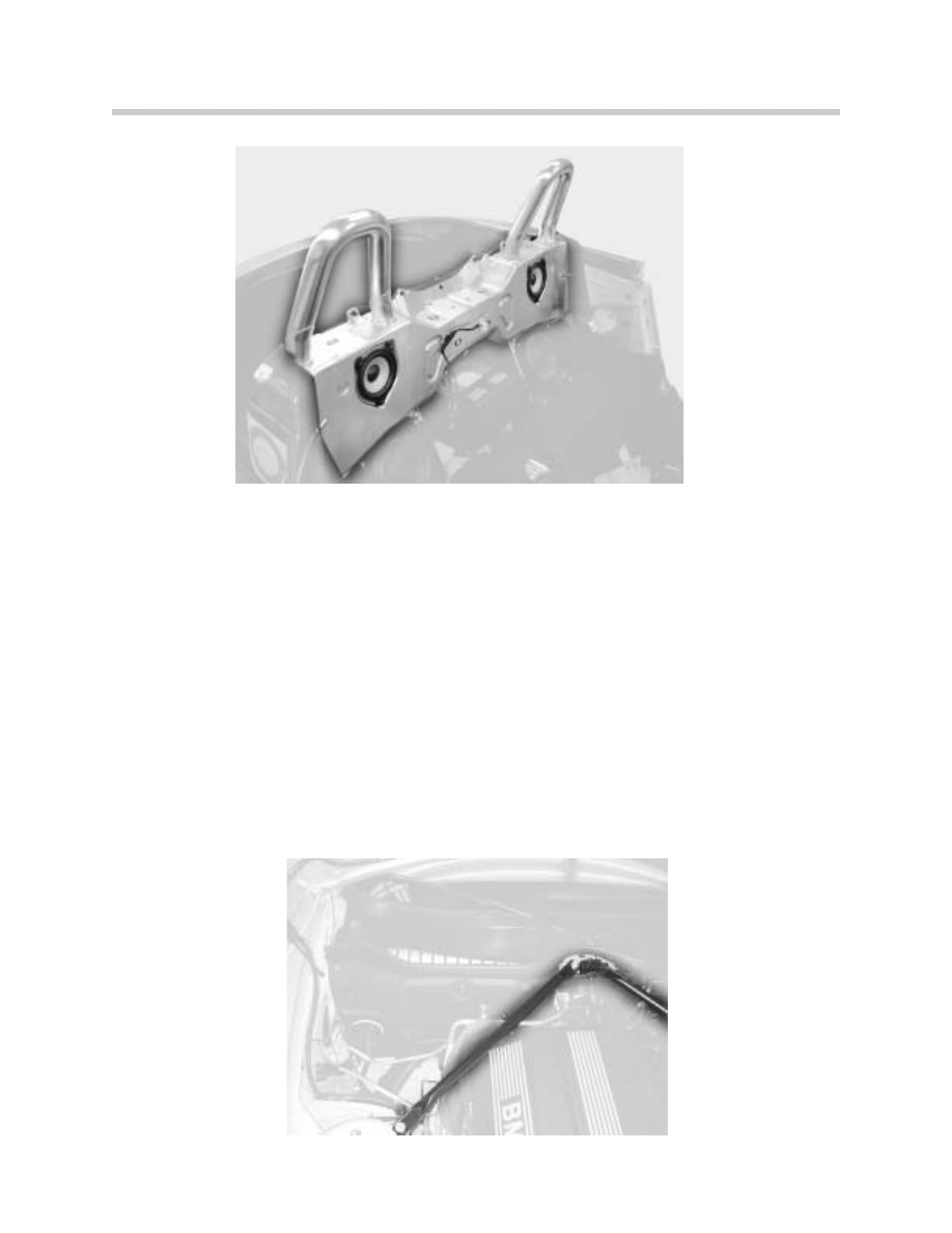
Torsional rigidity
There are extra cross-braces between the suspension-strut mountings and the engine-
compartment bulkhead. These increase the torsional rigidity. In the event of a serious
impact, the braces bend at a designed buckling point.
There are also additional reinforcing components for increasing torsional rigidity at the rear
(cross-braces) and in the underbody area (2 thrust plates).
Document Outline
- Main Menu
- E85 Complete Vehicle
- E85 BodyShell
- M54 Engine
- MS45 DME Part 1
- MS45 DME Part 2
- MS45 DME Part 3
- MS45 DME Part 4
- E85 Driveline
- E85 Chassis Dynamics
- E85 Heating & Air Conditioning System
- E85 Power Supply
- E85 Adv. Safety Electronics
- E85 Driver Information
- E85 Central Body Electronics
- E85 Communications
- E85 Updates
Wyszukiwarka
Podobne podstrony:
02 Frame Body Panels Exhaust System
02 E63 64 Body Electrical
02 Frame Body Panels Exhaust System
02 E66 Body
Wyk 02 Pneumatyczne elementy
02 OperowanieDanymiid 3913 ppt
02 Boża radość Ne MSZA ŚWIĘTAid 3583 ppt
OC 02
PD W1 Wprowadzenie do PD(2010 10 02) 1 1
02 Pojęcie i podziały prawaid 3482 ppt
WYKŁAD 02 SterowCyfrowe
02 filtracja
02 poniedziałek
21 02 2014 Wykład 1 Sala
Genetyka 2[1] 02
więcej podobnych podstron