
Initial Print Date: 03/06
Table of Contents
Subject
Page
System Circuit Diagram (Front Equipment - E65/E66) . . . . . . . . . . . . . .6
Connection of Control Units . . . . . . . . . . . . . . . . . . . . . . . . . . . . . . . . . . . . .9
System Circuit Diagram (E60/E61/E63/E64) . . . . . . . . . . . . . . . . . . . . . .10
Night Vision Camera . . . . . . . . . . . . . . . . . . . . . . . . . . . . . . . . . . . . . . . .13
Night Vision Control Unit . . . . . . . . . . . . . . . . . . . . . . . . . . . . . . . . . . . . .14
Button in Light Switch Center . . . . . . . . . . . . . . . . . . . . . . . . . . . . . . . .14
Switch-On Conditions . . . . . . . . . . . . . . . . . . . . . . . . . . . . . . . . . . . . . . . . .16
Operation by iDrive . . . . . . . . . . . . . . . . . . . . . . . . . . . . . . . . . . . . . . . . . . . .17
Calling Up Menu . . . . . . . . . . . . . . . . . . . . . . . . . . . . . . . . . . . . . . . . .17
Zoom - Angle of View of Camera . . . . . . . . . . . . . . . . . . . . . . . . . . . . .18
Bend/Curve Mode . . . . . . . . . . . . . . . . . . . . . . . . . . . . . . . . . . . . . . . . . .19
Full Screen . . . . . . . . . . . . . . . . . . . . . . . . . . . . . . . . . . . . . . . . . . . . . . . . .20
Contrast and Brightness . . . . . . . . . . . . . . . . . . . . . . . . . . . . . . . . . . . . .20
Visibility . . . . . . . . . . . . . . . . . . . . . . . . . . . . . . . . . . . . . . . . . . . . . . . . . . . .21
Axial Camera Adjustment . . . . . . . . . . . . . . . . . . . . . . . . . . . . . . . . . . . . . .22
Vertical Camera Adjustment . . . . . . . . . . . . . . . . . . . . . . . . . . . . . . . . . . . .22
Replacing Camera Washer Jet . . . . . . . . . . . . . . . . . . . . . . . . . . . . . . . . . .22
Displays in Event of a Fault . . . . . . . . . . . . . . . . . . . . . . . . . . . . . . . . . . . . .23
Component Location . . . . . . . . . . . . . . . . . . . . . . . . . . . . . . . . . . . . . . . . . .24
BMW Night Vision
Revision Date:

BMW Night Vision
Model: E60, E61, E63, E64, E65, E66
Production: March 2006
After completion of this module you will be able to:
• Familiarize yourself with the technology used in the BMW Night Vision system
• Know which components are responsible for the system’s operation
• Understand how to utilize the BMW Night Vision Feature
• Know the benefits to having this technology in the vehicle
2
BMW Night Vision
3
BMW Night Vision
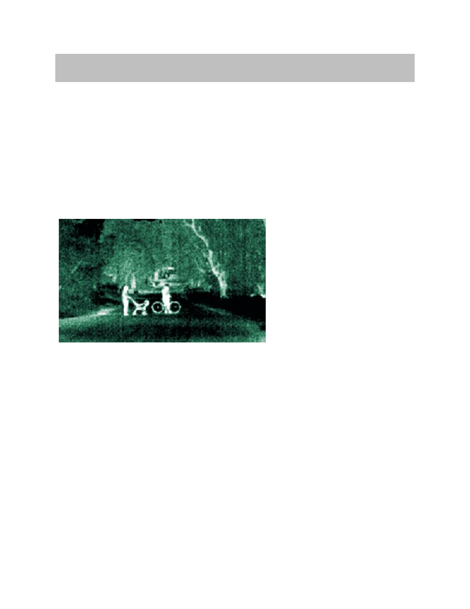
The BMW Night Vision system provides the driver with a black-and-white image of the
driving environment ahead of the vehicle in the central information display (CID).
BMW Night Vision is a 100% passive system without active infrared illumination. Objects
situated ahead of the vehicle are shown in varying degrees of brightness depending on
the temperature of these objects. This enables the driver to detect in good time heat-
emitting objects such as people, animals, and other vehicles.
This thermal image is recorded with a Far Infrared camera (FIR) via a special imaging
sensor which detects the infrared radiation in a specific wavelength range.
The BMW system is distinguished from infrared systems with active illumination by its
resistance to dazzling, its long range, and its clearly structured image.
The system offers the following advantages:
• Improved vision in conditions of dusk and darkness
• No dazzling by the headlights of oncoming vehicles
• Highlighting of unilluminated, heat-emitting objects such as pedestrians, cyclists
vehicles and deer, etc.
• Better overview of the driving situation thanks to the depiction of the route of the
road beyond the headlight cone
• Enlarged depiction thanks to the zoom function of objects in the far distance at high
speeds
• Illumination of bends/curves thanks to the bend/curve mode (pivoting of image
detail)
• Illumination of dark courtyard and garage entrances
Note: The driving speed must be adapted to the relevant visibility conditions
in each case. BMW Night Vision is designed as a supporting system,
which, with a modified driving style, affords the driver an early, better
overview of the road conditions ahead of the vehicle.
Introduction
Image taken from CID
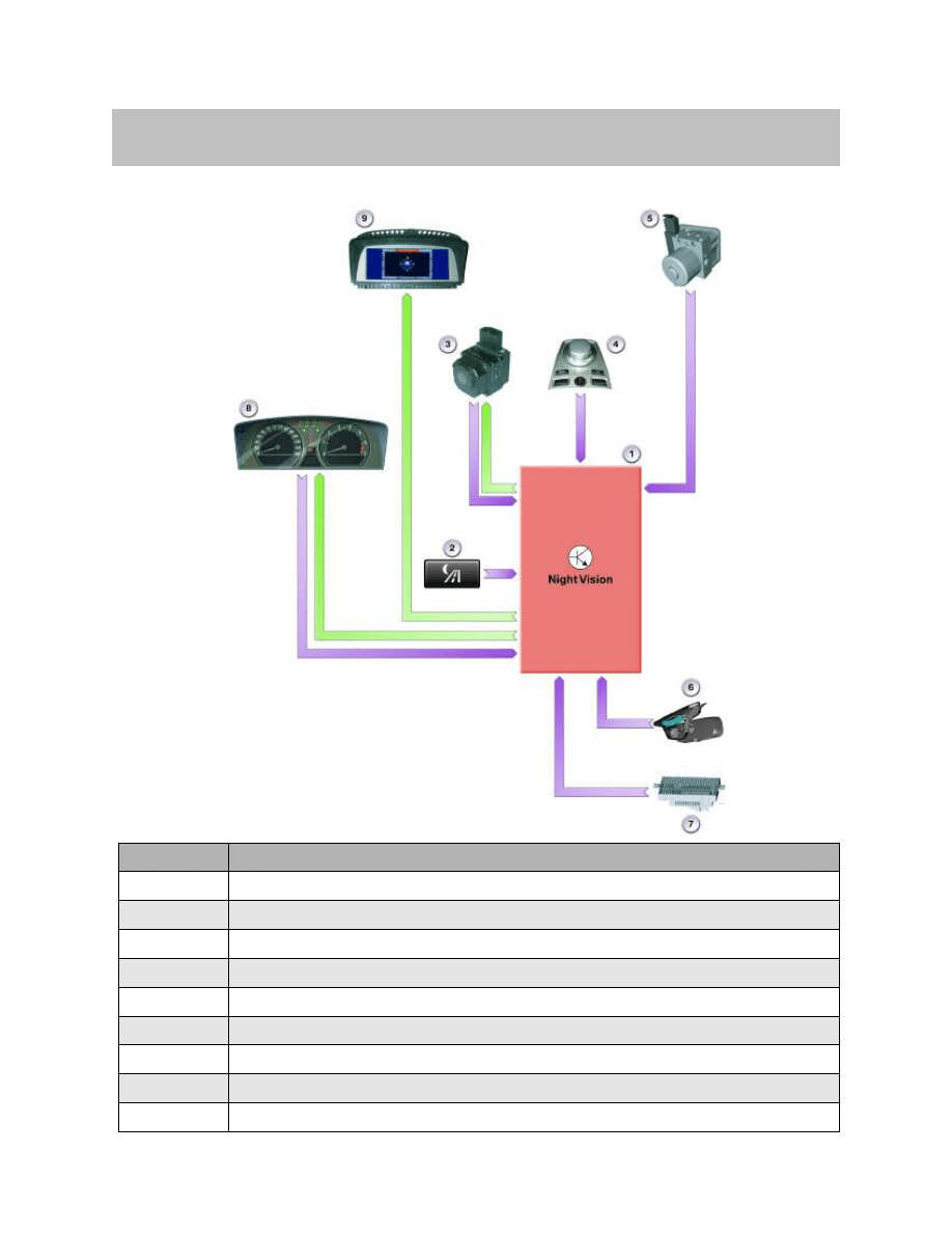
IPO Diagram (E65/E66)
4
BMW Night Vision
System Overview
Index
Explanation
1
Night Vision control unit
2
Button in light switch center
3
Night Vision camera
4
Controller
5
Dynamic Stability Control
6
Rain/light sensor
7
Light module
8
Instrument cluster
9
Control display

Connection of Control Units
Control Unit and Camera
The Night Vision control unit and the Night Vision camera are connected via the following
cables:
• LIN bus;
Diagnosis, programming and camera control
• Sym. Video;
Video signal from the camera
• CAN_POW;
Power supply from control unit to camera, heating of camera lens
• Ground;
Common earth/ground of camera and control unit for suppressing interference
The video signal between the camera and the control unit is transmitted via two cables as
a symmetrical, Analog video differential signal.
In the control unit the differential signal is converted into a CVBS signal and, depending
on the equipment specification, transmitted to the navigation system or the video module.
The camera is powered under the following conditions:
• Switching on of BMW Night Vision by the button in the light switch center
• Rain/light sensor detects dusk/half-light (driving lights are switched on)
The BMW Night Vision control unit is powered by the front distribution box via term. 30B.
K-CAN
The K-CAN connection of the Night Vision control unit serves to transmit the diagnosis
and programming data and to read out the information from the RLS (brightness), the LM
(driving lights on) and DSC (yaw rate, speed and steering angle). The signals from DSC
are placed on the K-CAN via the SGM. In addition, the control unit receives information
on the terminal status via the K-CAN.
5
BMW Night Vision
6
BMW Night Vision
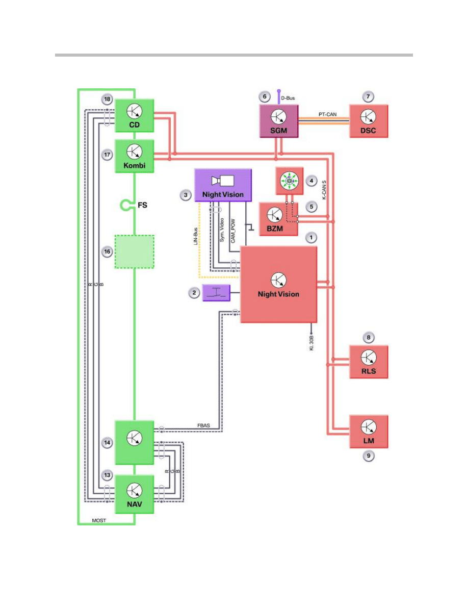
System Circuit Diagram (Front Equipment - E65/E66)

Legend for System Circuit Diagram
7
BMW Night Vision
Index
Explanation
Index
Explanation
1
Night Vision ECU
18
Control Display
2
Button in Light Switch Center
D-Bus
Diagnosis Bus
3
Night Vision Camera
PT-CAN
Powertrain CAN
4
Controller
K-CAN
Body CAN
5
Center Console Switch Cluster
MOST
Media Oriented System Transport
6
Safety Gateway Module
LIN-Bus
Local Interconnect Network Bus
7
Dynamic Stability Control
Kl. 30B
Continuous Positive
8
Rain/light Sensor
Sym. Video
Symmetrical, Analog Video
Differential Signal
9
Light Module
CAN_POW
Power Supply, Night Vision Camera
13
Navigation System
RGB
Red-Green-Blue Video Signal Cable
14
Video Switch, Drive
FBAS
Composite Video Burst
Synchronization Signal
16
MOST Components (optional)
FS
MOST Direct Access
17
Instrument Cluster
8
BMW Night Vision
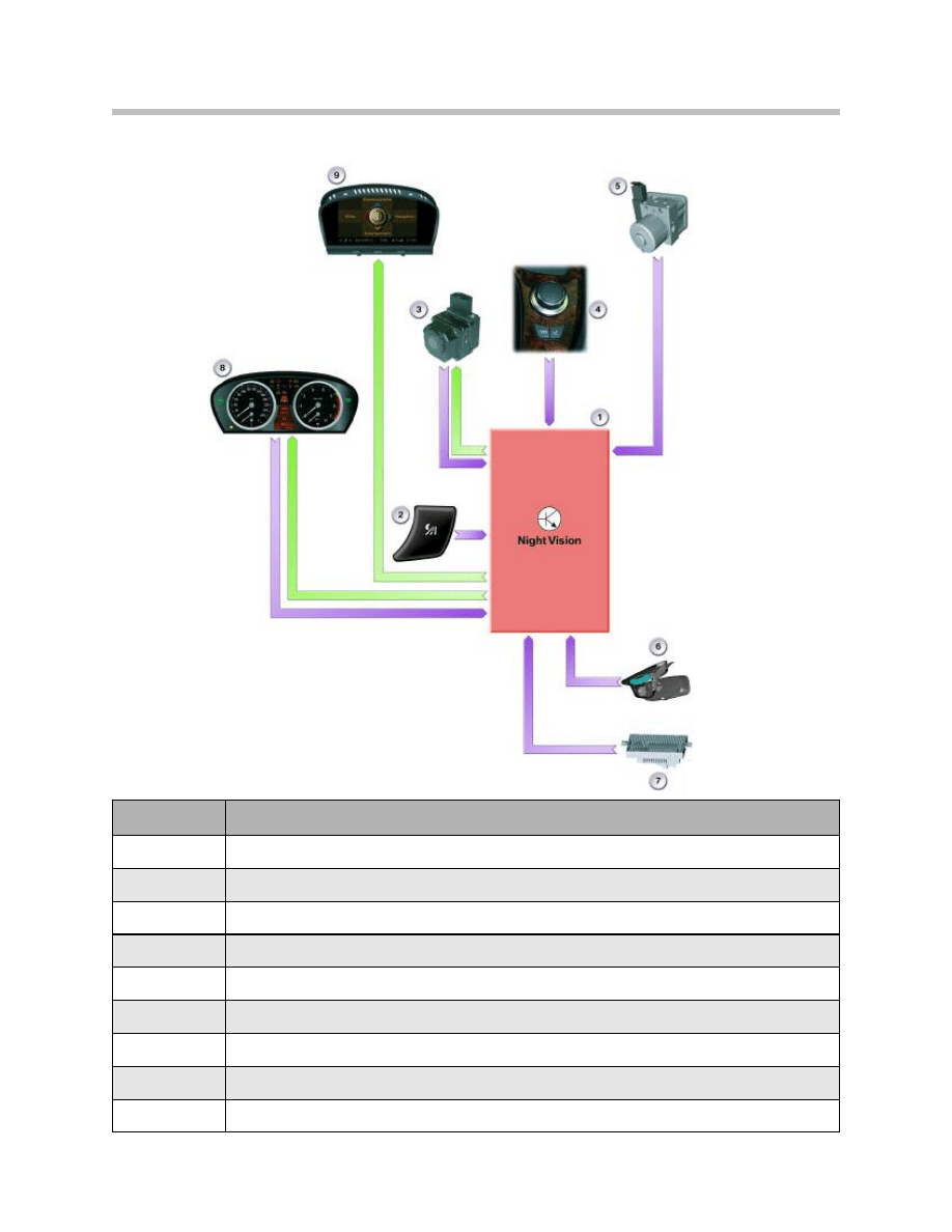
IPO Diagram (E60/E61/E63/E64)
Index
Explanation
1
Night Vision Control Unit
2
Night Vision Button on Light Switch
3
Night Vision Camera
4
Controller
5
Dynamic Stability Control
6
Rain/Light Sensor
7
Light Module
8
Instrument Cluster
9
Central Information Display

Connection of Control Units
Control Unit and Camera
The Night Vision control unit and the Night Vision camera are connected via the following
cables:
• LIN bus;
Diagnosis, programming and camera control
• Sym. Video;
Video signal from the camera
• CAN_POW;
Power supply from control unit to camera, heating of camera lens
• Ground;
Common ground of camera and control unit for suppressing interference
The video signal between the camera and the control unit is transmitted via two cables as
a symmetrical, Analog video differential signal.
In the control unit the differential signal is converted into a CVBS signal and, depending
on the equipment specification, transmitted to the navigation system or the video module.
The camera is powered under the following conditions:
• Switching on of BMW Night Vision by the button in the light switch center
• Rain/light sensor detects dusk/half-light (driving lights are switched on)
The BMW Night Vision control unit is powered by the front distribution box via term. 30B.
K-CAN
The K-CAN connection of the Night Vision control unit serves to transmit the diagnosis
and programming data and to read out the information from the RLS (brightness), the LM
(driving lights on) and DSC (yaw rate, speed and steering angle). The signals from DSC
are placed on the K-CAN via the KGM. In addition, the control unit receives information
on the terminal status via the K-CAN.
9
BMW Night Vision
10
BMW Night Vision
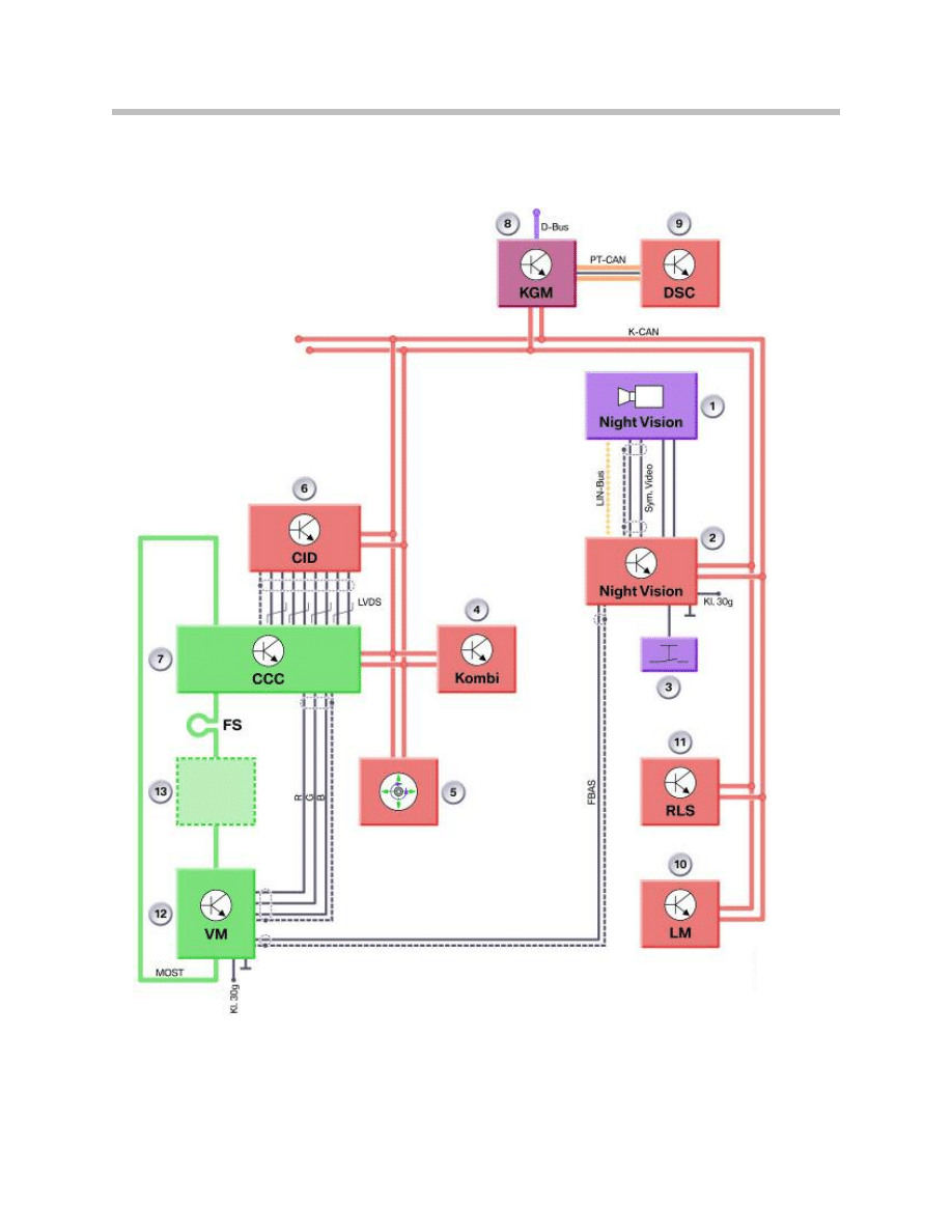
System Circuit Diagram (E60/E61/E63/E64)

11
BMW Night Vision
Legend for System Circuit Diagram (E60/E61/E63/E64)
Index
Explanation
Index
Explanation
1
Night Vision Camera
13
MOST Components (optional)
2
Night Vision Control Unit
D-Bus
Diagnosis Bus
3
Button in Light Switch Center
PT-CAN
Powertrain CAN
4
Instrument Cluster
K-CAN
Body CAN
5
Controller
MOST
Media Oriented System Transport
6
Central Information Display
LIN-Bus
Local Interconnect Network Bus
7
Car Communication Computer
Sym. Video
Symmetrical, Analog Video
Differential Signal
8
Body Gateway Module (KGM)
CAN_POW
Power Supply, Night Vision Camera
9
Dynamic Stability Control
RGB
Red-Green-Blue Video Signal Cable
10
Light Module
FBAS
Composite Video Burst
Synchronization Signal
11
Rain/light Sensor
FS
MOST Direct Access
12
Video Switch, Drive
Components
The BMW Night Vision system consists of the following components:
• Night Vision camera with camera bracket and camera washer jet
• Night Vision control unit
• Button in light switch center
• Sensor system
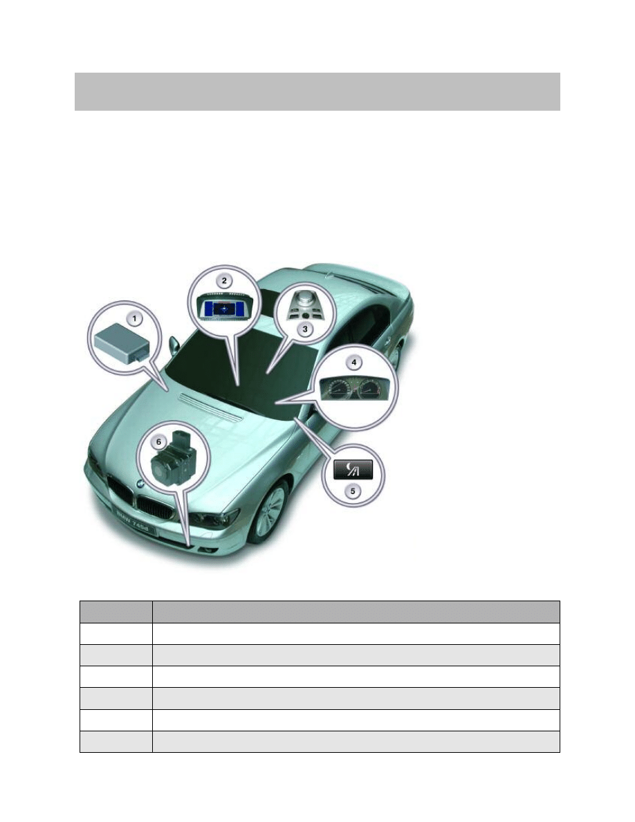
12
BMW Night Vision
Night Vision installation Locations
Index
Explanation
1
Night Vision Control Unit
2
Control Display
3
Controller
4
Instrument Cluster
5
Button in Light Switch Center
6
Night Vision Camera
System Components
Night Vision Camera
The thermal imaging camera consists of a heated
optical element and a thermal imaging sensor. The
thermal imaging sensor is made up of a multitude
of sensor elements.
Each display pixel is assigned one such sensor ele-
ment. The sensor elements generate an electrical
signal as a function of the impinging intensity of
heat radiation.
The higher the temperature, the brighter the corre-
sponding pixel will be displayed. The heat radiation
is converted into electrical signals on the basis of
the principle of a change in resistance.
The image can be replaced up to 60 times per second. In order to ensure an image
of consistent quality, it is necessary for the camera to be calibrated roughly every 120
seconds. This calibration can take up to approx. 0.5 seconds. For this reason, the image
may be seen to freeze in the display.
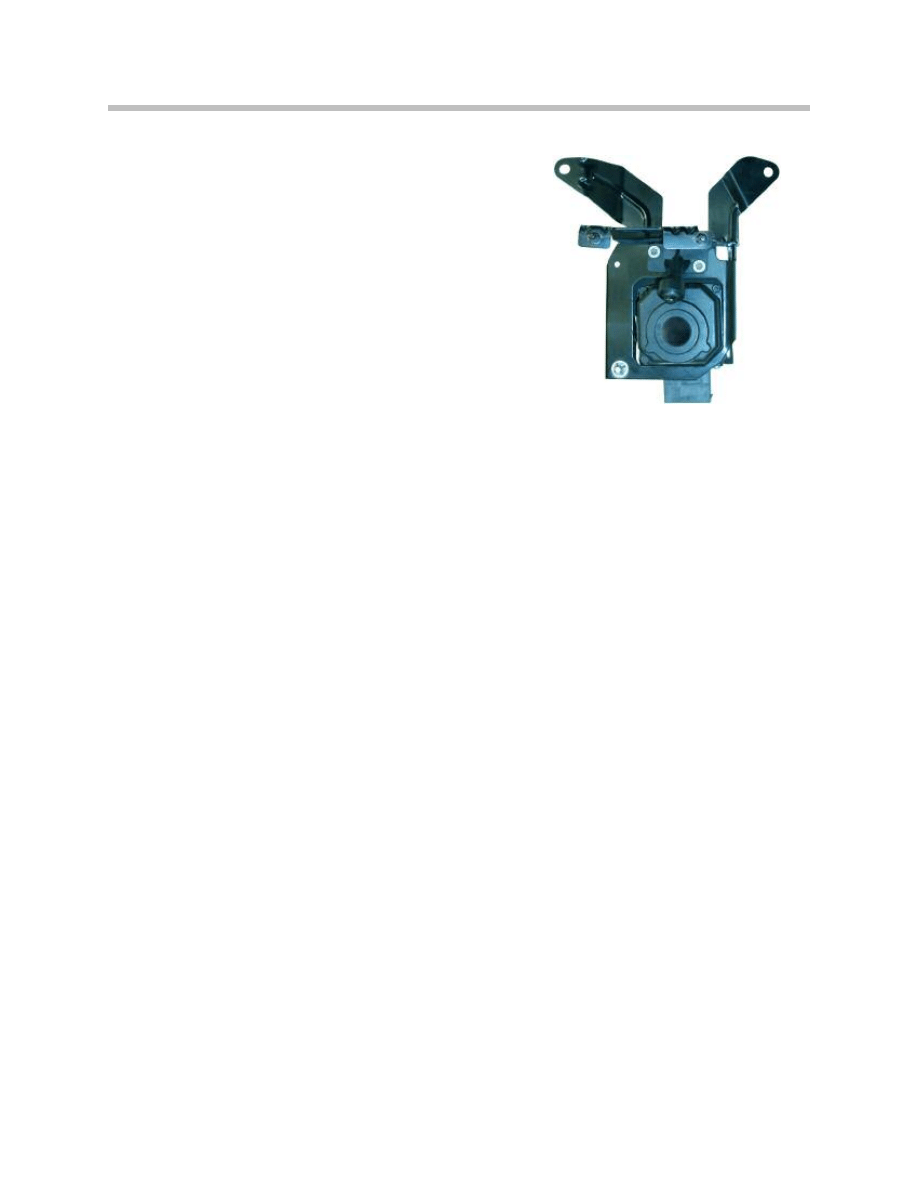
The Night Vision camera is mounted with a bracket directly behind the left ventilation
grille on the bumper mounting bracket.
The camera is equipped with a sensor which detects heat-emitting objects in the Far
Infrared range (wavelengths from 8
mm to 15 mm).
The camera resolution is 320 x 240 pixels. The maximum angle of view is 36°. The
calculations for the "Bend/curve mode" functions are made in the camera. The camera
operates in an ambient-temperature range of - 104°F to 185°F (40°C to +85°C). The
camera and imaging sensor are thermally insulated to provide protection against heat
influences from the camera surroundings.
The washer jet is screwed to the camera bracket and is situated directly above the
camera's front lens. It is directly connected to the headlight washer system and therefore
operates in conjunction with the latter.
A heater element is incorporated on the inside of the camera-housing cover to prevent
the optical element from misting over or freezing up. The heater is activated when the
rain/light sensor detects precipitation or at temperatures below 32°F (0°C).
13
BMW Night Vision
Camera with Bracket (E65 shown)
Night Vision Control Unit
The control unit is accommodated in the front
device holder behind the glovebox.
The control unit increases the image data from
the camera from 320 x 240 pixels to 640 x 480
pixels. Only one detail is shown in the control
display. 640 x 240 pixels are displayed when the
"Full screen" function is activated while 400 x
240 pixels are displayed for the splitscreen function. The diagnosis, programming and
coding data are transmitted to the camera via the control unit.
The camera and the front-lens heater are powered via the control unit. In addition, the
control unit converts the symmetrical image data from the camera into a CVBS signal
and, depending on the equipment specification, makes this signal available to either the
navigation system or the video module.
The Night Vision control unit is accommodated in the front device holder behind the
glovebox.
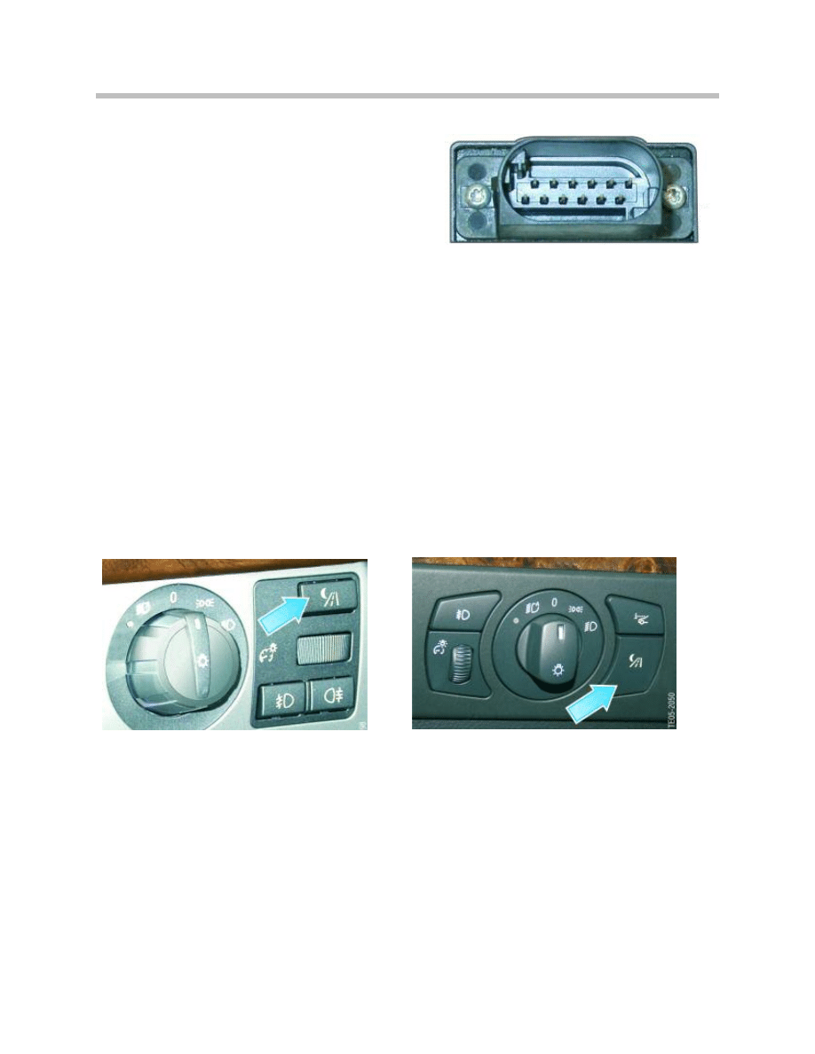
The camera-housing cover features a 12-pin plug connection.
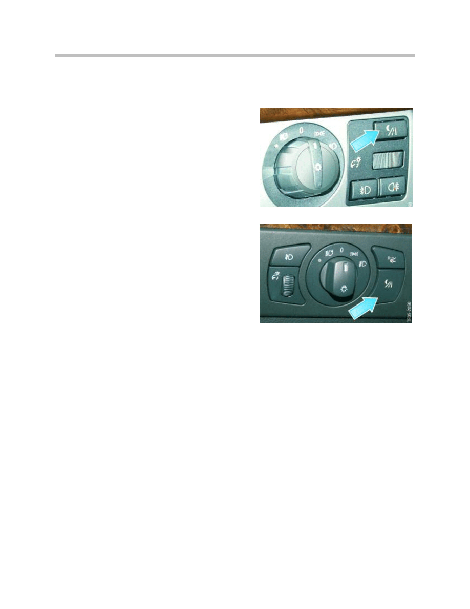
Button in Light Switch Center
The button for switching BMW Night Vision on and off is integrated in the light switch
center.
14
BMW Night Vision
12-pin Plug Connection
Switch/Button on E65/66
Switch/Button on E60/E61/E63/E64
Principles of Operation
The BMW Night Vision camera is a thermal imaging camera, which converts thermal
radiation into electronic signals and then into images visible to the human eye.
The thermal image is converted first by the sensor into electrical signals and then with
the aid of image-processing software into a visible image in the control display.
The sensor elements alter the resistance in proportion to the temperature. The higher
the temperature, the higher the electrical signal and the whiter the pixel will be shown.
Thanks to increased dynamic sensitivity, the sensor can generate a new image up to 60
times per second. This results in a softer and clearer image.
Heat radiation is absorbed and dissipated by virtually every solid or liquid body. Heat
radiation, however, is not visible to the human eye because it belongs in the long-wave
infrared range. From a physical standpoint, this represents electromagnetic waves with
a wavelength of 8
mm to 15 mm. This long-wave infrared radiation is known as Far
Infrared (FIR).
The advantage of utilizing radiation in the Far Infrared range is the greater range com-
pared with Near Infrared systems with a wavelength of 0.7
mm to 1.4 mm. These systems
require illumination with just this wavelength.
Essentially, FIR systems consist of an optical element, a thermal imaging camera, an
control unit and a display.
15
BMW Night Vision
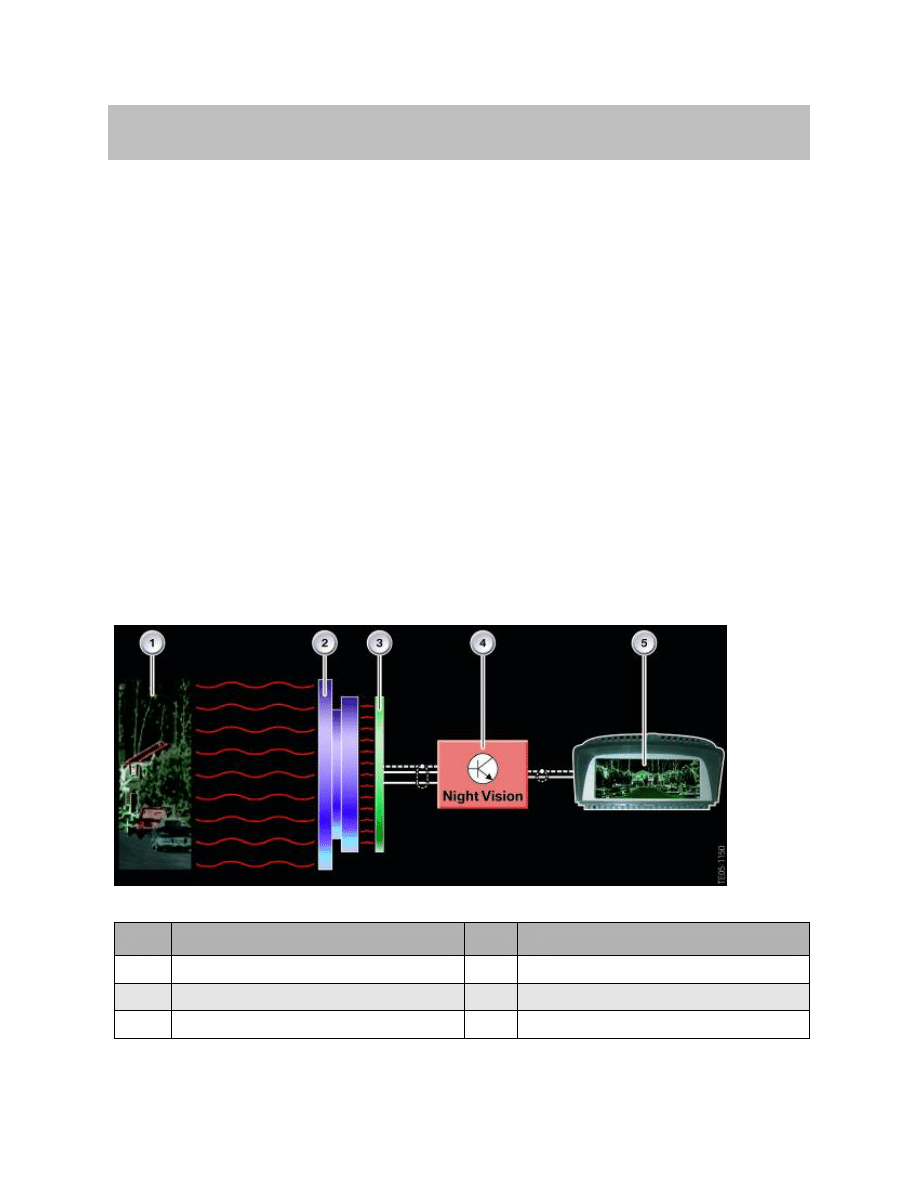
Index
Explanation
Index
Explanation
1
Environment ahead of vehicle
4
BMW Night Vision control unit
2
Optical element
5
Central Information Display
3
Thermal Imaging Sensor
Diagram Representing Principle of Operation
Switch-On Conditions
BMW Night Vision is activated as soon as the button in the light switch center is pressed.
The following basic conditions can exist:
• The rain/light sensor detects sufficient
ambient light and the driving lights are
switched off; BMW Night Vision is ready for
operation approx. 2 seconds after the button
in the light switch center is pressed. A mes-
sage is shown in the control display during
this period of 2 seconds.
• The rain/light sensor detects insufficient
ambient light and the driving lights are
switched on; BMW Night Vision is ready for
operation immediately after the button is
pressed.
• In conditions of darkness (underground
car park), the driving lights are switched off
and the driving speed is less than 5 km/h;
BMW Night Vision is ready for operation
after the button in the light switch center is
pressed.
BMW Night Vision cannot be activated when:
• the driving lights are switched off,
• the rain/light sensor detects insufficient ambient light, and
• the driving speed is greater than 5 km/h
Once BMW Night Vision has been activated, a message appears in the control display to
the effect that the system cannot be used at night without driving lights.
16
BMW Night Vision
Switch/Button on E65/66
Switch/Button on E60/E61/E63/E64
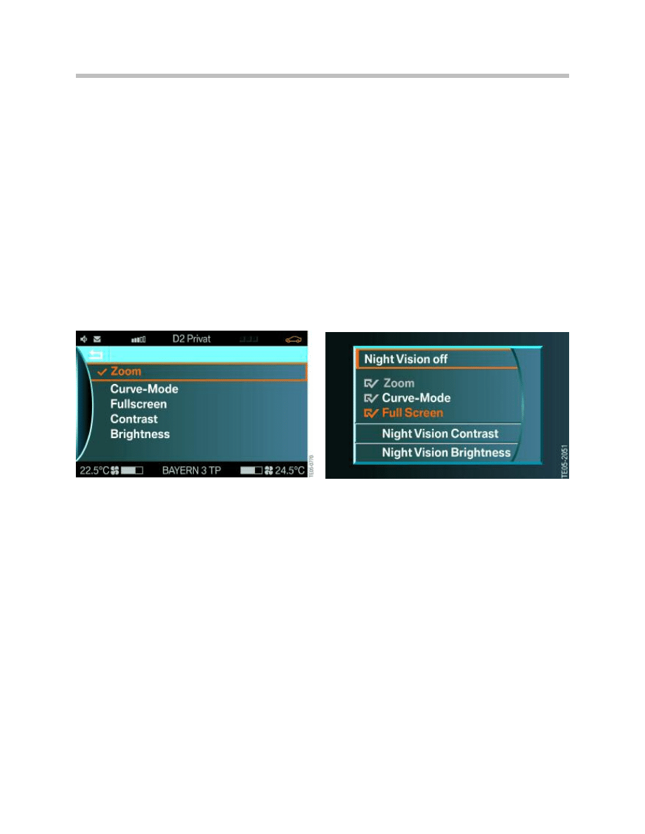
Operation by iDrive
Calling up Settings
The individual functions and settings can be selected and activated via the iDrive.
The following settings can be called up:
• Night Vision off (not E65)
• Zoom
• Curve mode
• Full screen
• Contrast
• Brightness
A tick/check symbol indicates when zoom, bend/curve mode or full screen is activated.
Calling Up Menu
The BMW Night Vision menu can only be called up when the system is activated.
When the preconditions are in place, the menu can be called up for example from the
Start menu as follows:
• Briefly press the controller. The "BMW Night Vision" menu appears in the control
display
• Select the desired menu item, e.g. "Brightness", by turning the controller
• Press the controller to activate the function
• Set the desired value and confirm by pressing
• Select the menu item "Back" and quit the "BMW Night Vision" menu
17
BMW Night Vision
E65/E66 Settings Menu
E60/E61/E63/E64 Settings Menu
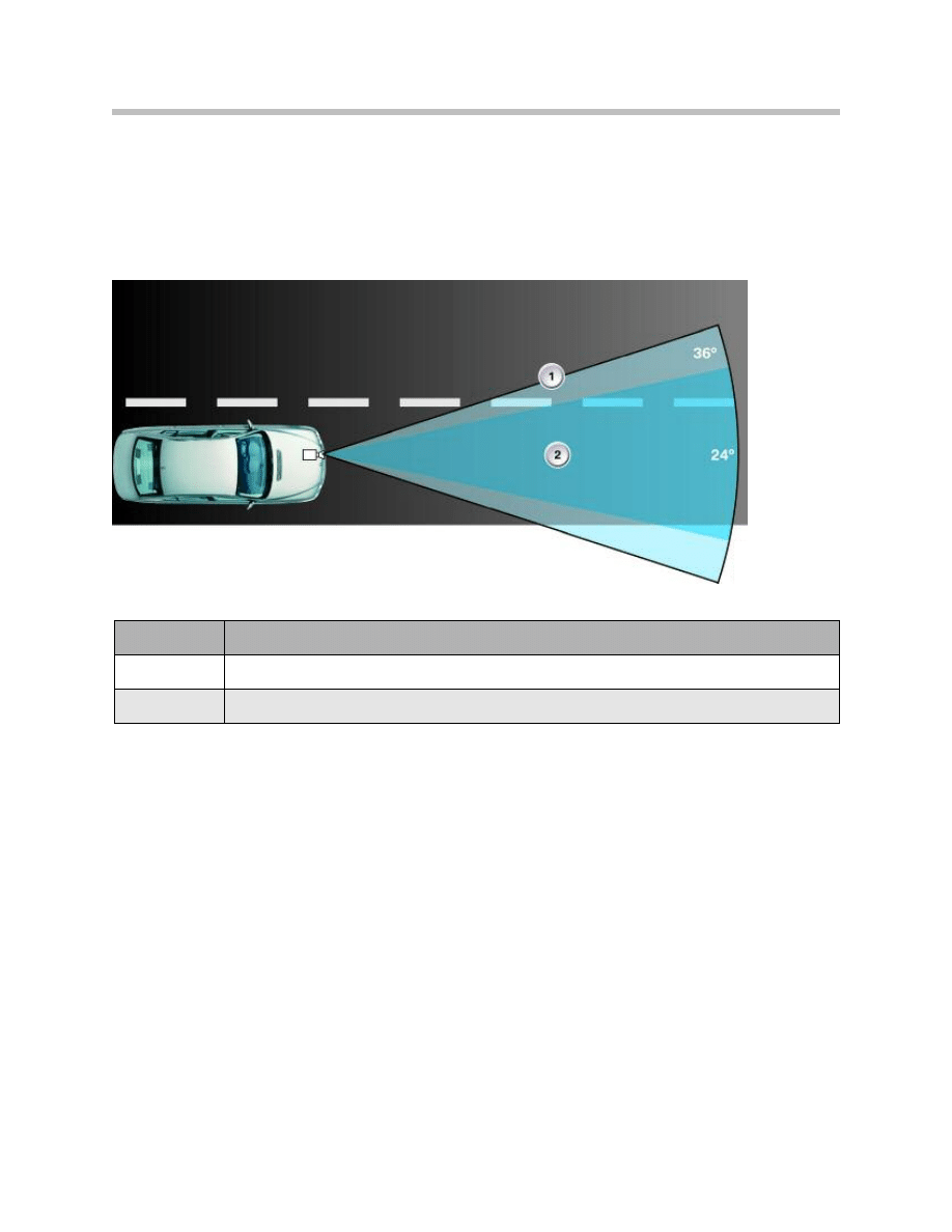
Zoom - Angle of View of Camera
When the "Zoom" function is activated, BMW Night Vision automatically switches to a
1.5 times enlargement of the display at speeds in excess of 44 mph (70 km/h). The cam-
era's angle of view is reduced to 24° here. Zoom is deactivated automatically again when
the speed drops below 37 mph (60 km/h). The camera's angle of view reverts to 36°.
Zoom is calculated by the camera.
Note: The "Zoom" function can only be selected when the "Full screen" func-
tion is deactivated.
18
BMW Night Vision
Index
Explanation
1
Angle of view of 36° without zoom
2
Angle of view of 24° with zoom
Angle of View of Camera
Bend/Curve Mode
Depending on the driving situation, the image detail follows the cornering path of the
vehicle along the same lines as the directional headlights.
The image detail is calculated in the camera.
Bend/curve mode is only available when the "Zoom" function is activated.
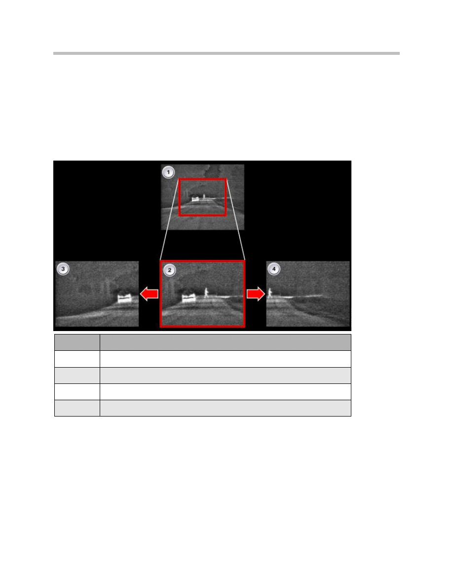
For better understanding, the following graphic shows a driving situation in which the
"Bend/curve mode" function is activated.
19
BMW Night Vision
Index
Explanation
1
Driving situation without zoom
2
Driving situation with zoom, direction of travel
3
Cornering to the left, enlarged 1.5 x
4
Cornering to the right, enlarged 1.5 x
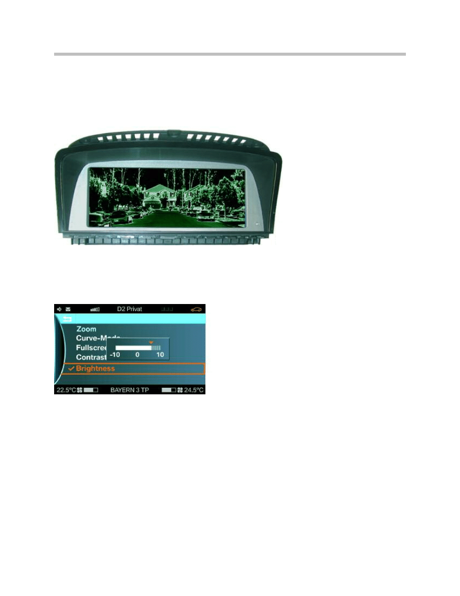
Full Screen
In the case of the "Full screen" function, the Assist window is removed and the thermal
image is shown over the entire width of the control display. 640 x 240 pixels (for full
screen) and 400 x 240 pixels (for split screen) are used to display the BMW Night Vision
image.
Contrast and Brightness
Both values can be personalized and changed on a scale between -10 and 10.
20
BMW Night Vision
Full Screen in Control Display
Adjusting Brightness
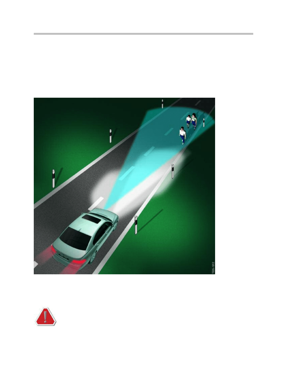
Visibility
Normal driving-light illumination is approximately 328 ft (150 m).
The use of BMW Night Vision enables heat emitting objects to be detected
up to a distance of approx. 984 ft (300 m).
This specified distance is dependent on weather factors.
For example, heavy fog or rain reduces visibility.
The driving speed must be adapted to the relevant visibility conditions
in each case. BMW Night Vision is designed as a supporting system,
which, with a modified driving style, affords the driver an early, better
overview of the road conditions ahead of the vehicle.
21
BMW Night Vision
Comparison of BMW Night Vision Visibility with Different Vehicle Headlights
22
BMW Night Vision
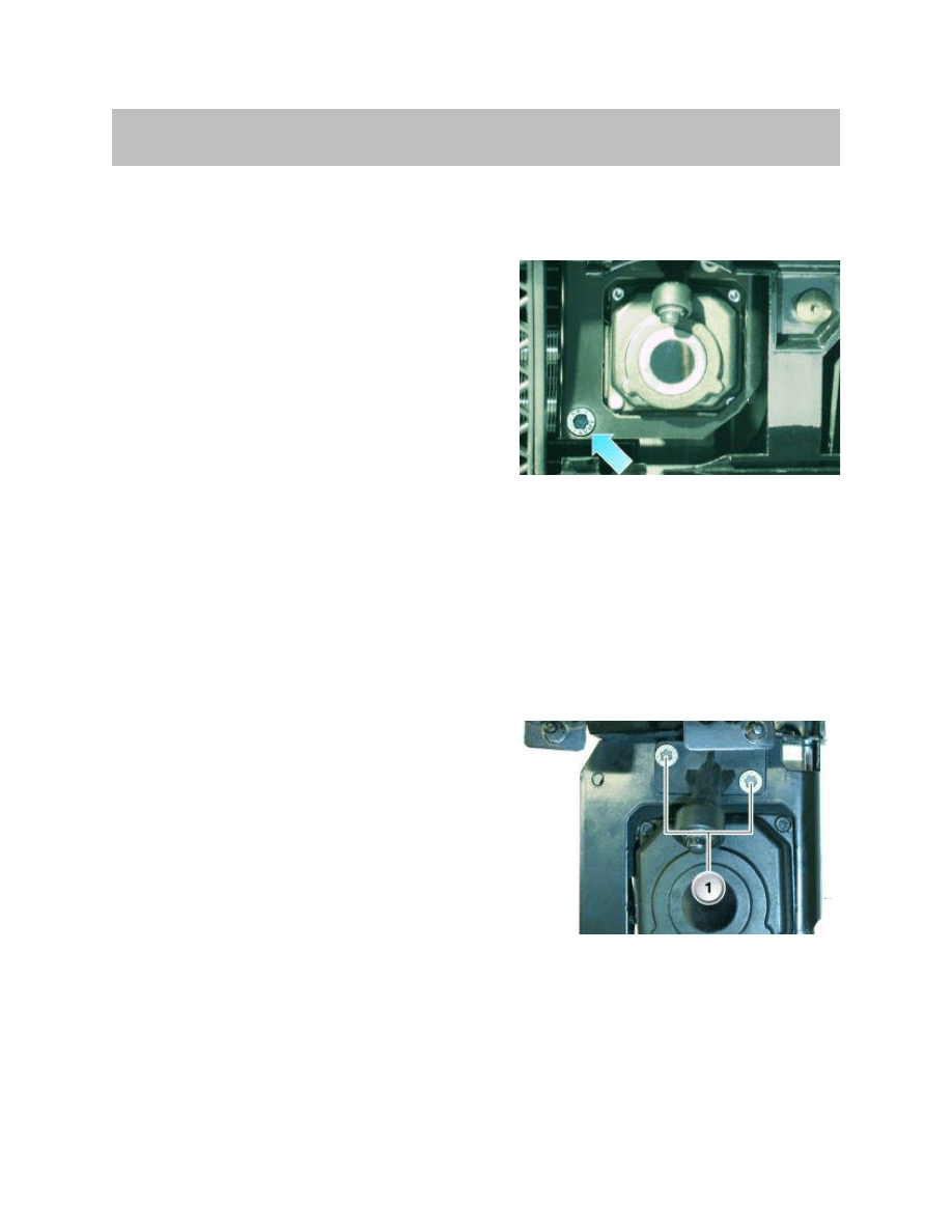
Axial Camera Adjustment
The camera can be axially readjusted by means of an adjusting screw on the housing.
The following procedure must be performed:
• Detach the left ventilation grille from the
front spoiler
• Position the headlight aiming device in
front of the vehicle
• Engage a Torx screwdriver and move the
camera to the desired position
• Reassemble all parts that have been
removed in reverse order
Vertical Camera Adjustment
Vertical camera adjustment should be adjusted until the horizontal plane is centered on
the CD/CID. This adjustment is only possible through a test plan in the BMW tester.
Replacing Camera Washer Jet
A washer jet with a direct connection to the headlight washer system for cleaning the
lens is mounted on the camera.
Follow the procedure below to replace the
washer jet:
• Detach the left ventilation grille from the
front spoiler
• Release the two Torx screws (1)
• Release the hose clamp on the connecting
hose to the headlight washer system and
detach the washer jet towards the front
• Reinstall all parts that have been removed
in reverse order
Note: Please refer to the repair instructions for more detailed information on
removing the camera and washer jet.
Camera Adjustment
Washer Jet Mounting Position
Service Information
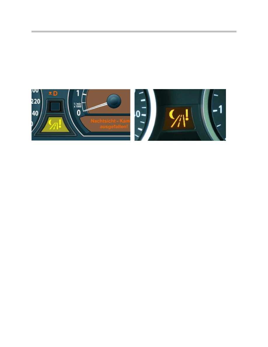
Displays in Event of a Fault
The following warnings are displayed if the camera is faulty:
• Check control icon in the instrument cluster
• A symbol/description is also shown in CD or CID
• Check control message in the cluster under the tachometer (E65/E66 only)
Initialization
When replacing the camera, it is always necessary to initialize the software by entering
a clearance code (FSC).
The camera is programmed by means of a control unit. The control unit receives the
programming and coding data for the camera via the K-CAN. The control unit forwards
these data to the camera via the LIN bus.
23
BMW Night Vision
Displays in Event of a Fault (E65/E66)
Displays in Event of a Fault (E60/E61/E63/E64)
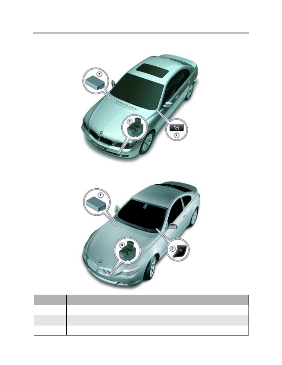
Component Location
24
BMW Night Vision
E65/E66
E60/E61/E63/E64
Index
Explanation
1
Night Vision Control Unit
2
On/off button for Night Vision System
3
Far infrared thermal imaging camera
Document Outline
- Main Menu
- Intro to Advanced Body Electronics
- E65 Power Management
- E65 Power Module
- E65 Car Access System
- E65 Driver Information
- E65 Body Electronics
- E65 Central Body Electronics
- E65 Remote Control Services
- E65 Automatic Trunk Lid Lift
- E65 Windshield Wiping Washing
- E65 Seat, Mirror and Steering Column
- E65/66 Model Update
- E65/66 Comfort Access
- E6x Voltage Supply and Bus Systems
- E6x Body Electronics
- E6x Body Electronics
- E6x 9/05 Model Updates
- E6x Driver Information Systems
- E90 Voltage Supply and Bus Systems
- E90 General Vehicle Electrical
- E90 General Vehicle Electrical
- E90 General Vehicle Electrical II
- E90 Driver Information Systems
- E90 Entertainment and Communication
- Car Communication Computer
- Head-Up Display
- Head-Up Display (First Generation)
- E70 Head-Up Display (Second Generation)
- E70 Audio Systems
- BMW Night Vision
- Glossary
Wyszukiwarka
Podobne podstrony:
06 3 F01 BMW Night Vision 2
BMW Night Vision(1)
17 BMW New CKM Introduction & Setting
17 A Hard Day s Night Searcher (s) (Rafael & Celena)
SII 17 Technologie mobilne
17 Metodologia dyscyplin praktycznych na przykładzie teorii wychowania fizycznego
13 ZACHOWANIA ZDROWOTNE gr wtorek 17;00
prezentacja 17
Giddens środa 17 15
17 Tydzień zwykły, 17 wtorek
kinezyterapia 17 10, POSTAWA CIAŁA I KRYTERIA JEJ OCENY
Odwodnienie (dehydratatio) (17 12 2010 i 7 01 2011)
17 G11 H09 Składniki krwi wersja IHiT
CHF dr gębalska 17 01 03
CECHY STRUKTUR ORGANIZACYJNYCH PRACA GRUPOWA 17 KWIETNIA[1]
lec6a Geometric and Brightness Image Interpolation 17
więcej podobnych podstron