
Hardware and Engineering
LE 4-206-AA2
Analog LE for Current Signals
09/99 AWB 2700-1331 GB
1st published 1998, edition 07/98
2nd published 1999, edition 09/99
© Moeller GmbH, Bonn
Author:
Peter Roersch
Editor:
Karola Großpietsch
Translator:
Terence Osborn

Caution!
Dangerous electrical voltage!
Before commencing the installation
●
Disconnect the power supply of the
device.
●
Ensure that the device cannot be
accidentally restarted.
●
Verify isolation from the supply.
●
Earth and short circuit.
●
Cover or enclose neighbouring units that
are live.
●
Follow the engineering instructions
(AWA) of the device concerned.
●
Only suitably qualified personnel may
work on this device/system.
●
Before installation and before touching
the device ensure that you are free of
electrostatic charge.
●
Connecting cables and signal lines
should be installed so that inductive or
capacitive interference do not impair the
automation functions.
●
Install automation devices and related
operating elements in such a way that
they are well protected against
unintentional operation.
●
Suitable safety hardware and software
measures should be implemented for
the I/O interface so that a line or wire
breakage on the signal side does not
result in undefined states in the
automation devices.
●
Ensure a reliable electrical isolation of
the low voltage for the 24 volt supply.
Only use power supply units complying
with IEC 60 364-4-41 or HD 384.4.41 S2.
●
Deviations of the mains voltage from the
rated value must not exceed the
tolerance limits given in the
specifications, otherwise this may cause
malfunction and dangerous operation.
●
Emergency stop devices complying with
IEC/EN 60 204-1 must be effective in all
operating modes of the automation
devices. Unlatching the emergency-stop
devices must not cause uncontrolled
operation or restart.
●
Devices that are designed for mounting
in housings or control cabinets must only
be operated and controlled after they
have been installed with the housing
closed. Desktop or portable units must
only be operated and controlled in
enclosed housings.
●
Measures should be taken to ensure the
proper restart of programs interrupted
after a voltage dip or failure. This should
not cause dangerous operating states
even for a short time. If necessary,
emergency-stop devices should be
implemented.
IBM is a registered trademark of International
Business Machines Corporation.
All other brand and product names are
trademarks or registered trademarks of the
owner concerned.
All rights reserved, including those of the
translation.
No part of this manual may be reproduced in
any form (printed, photocopy, microfilm or
any otherprocess) or processed, duplicated
or distributed by means of electronic
systems without written permission of
Moeller GmbH, Bonn.
Subject to alterations without notice.

1
09/99 AWB 2700-1331 GB
Contents
Mounting on mounting plate via fixing feet
Installing in the control cabinet
Fitting/removing the terminal strip
11
Electromagnetic compatibility (EMC)
Connecting to the PS 4-200/300,
EM 4-204-DX1 13
Connecting analog cables
Configuration and Parameter Setting
19
Setting the input and output parameters
Setting parameters for the PROFIBUS-DP
network 22
Addressing/Operation/Diagnostics
23
Addressing 23
Operation 24
Diagnostics 25
Diagnostics for the PROFIBUS-DP network
31
41
43

2
09/99 AWB 2700-1331 GB

3
09/99 AWB 2700-1331 GB
About This Manual
This manual is written for engineers and technicians
with PLC experience.
It provides the special information required for
connecting the module correctly, as well as for
configuring and programming it with the
Sucosoft S 40 programming software.
To use this manual, a knowledge of the following is
required:
the master in use
the programming software
You will find the required information in:
the “Hardware and Engineering” manual of your
master
the manual “Sucosoft S 40, User Interface”
(AWB 2700-1305 GB)
the manual “Sucosoft S 40, Language Elements
for PS 4-... and PS 416” (AWB 2700-1306 GB)
About This Manual
4
09/99 AWB 2700-1331 GB
The symbols used in this manual have the following
meaning:
왘 Indicates handling instructions.
Attracts your attention to interesting tips and
additional information.
Note
Warns you of damage to property. Product, parts
in its surrounding or data may be severely
damaged
Caution!
Warns you of severe damage to property.
Product, parts in its surrounding or data may be
severely damaged

5
09/99 AWB 2700-1331 GB
1
About The LE 4-206-AA2
Application range
The LE 4-206-AA2 converts analog current signals of
0(4) to 20 mA into digital values, and digital values
into analog current signals of 0(4) to 20 mA.
In HVAC applications and in process engineering, it
can be used to process the analog signals of sensors
that record physical values such as pressure,
temperature, and flow rate. The analog output
currents can be used to regulate these variables.
The LE 4-206-AA2 can be used to expand the analog
I/O of the PS 4-200, PS 4-300 compact PLCs as well
as the EM 4-204-DX1 remote expansion module.
Two modules can be used for each PLC. They are
fitted directly to the side of the PLC in the first or
second position.
Special features
Type of inputs/outputs
0(4) to 20 mA
Number of I/O
4 inputs/2 outputs
Resolution
12 Bit
Error detection
Out-of-range values,
wire breakage, reverse polarity
About The LE 4-206-AA2
6
09/99 AWB 2700-1331 GB
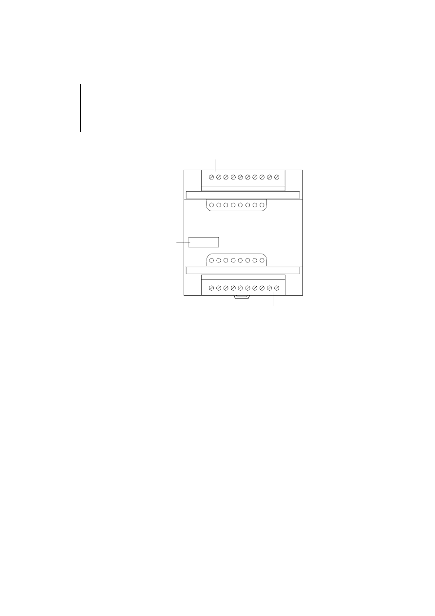
Setup
Figure 1: Setup of the LE 4-206-AA2
햲 Device designation with HAEG 18 3 6.5
햳 Plug-in screw terminal for the inputs/outputs
Software requirements
Sucosoft S 40 from version 3.0 is required for
configuring the LE 4-206-AA2 with the
PS 4-200/300.
0V
A
I
0
I
1
0V
A
LE4-206-AA2
Analog
Output
Analog
Input
0V
A
I
0
I
1
0V
A
0V
A
I
2
I
3
0V
A
햳
햲
햳
7
09/99 AWB 2700-1331 GB
2
Mounting
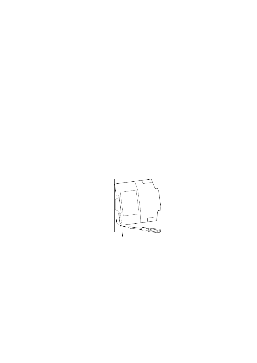
Mounting on top-hat
rail
The LE 4-206-AA2 can be fixed on a top-hat rail or on
a mounting plate via fixing feet. The relevant
dimensions are given in the Appendix.
왘 Hook the back of the device against the top edge
of the top-hat rail.
왘 Use a screwdriver to slide the spring-loaded clip
햲
out of the device
햳
.
왘 Push the device against the top-hat rail
햴
.
왘 Remove the screwdriver. The spring-loaded clip
should snap back into position and hold the
device securely.
왘 Check that the device is attached properly.
Figure 2: Mounting on top-hat rail
햲
햳
햴
Mounting
8
09/99 AWB 2700-1331 GB
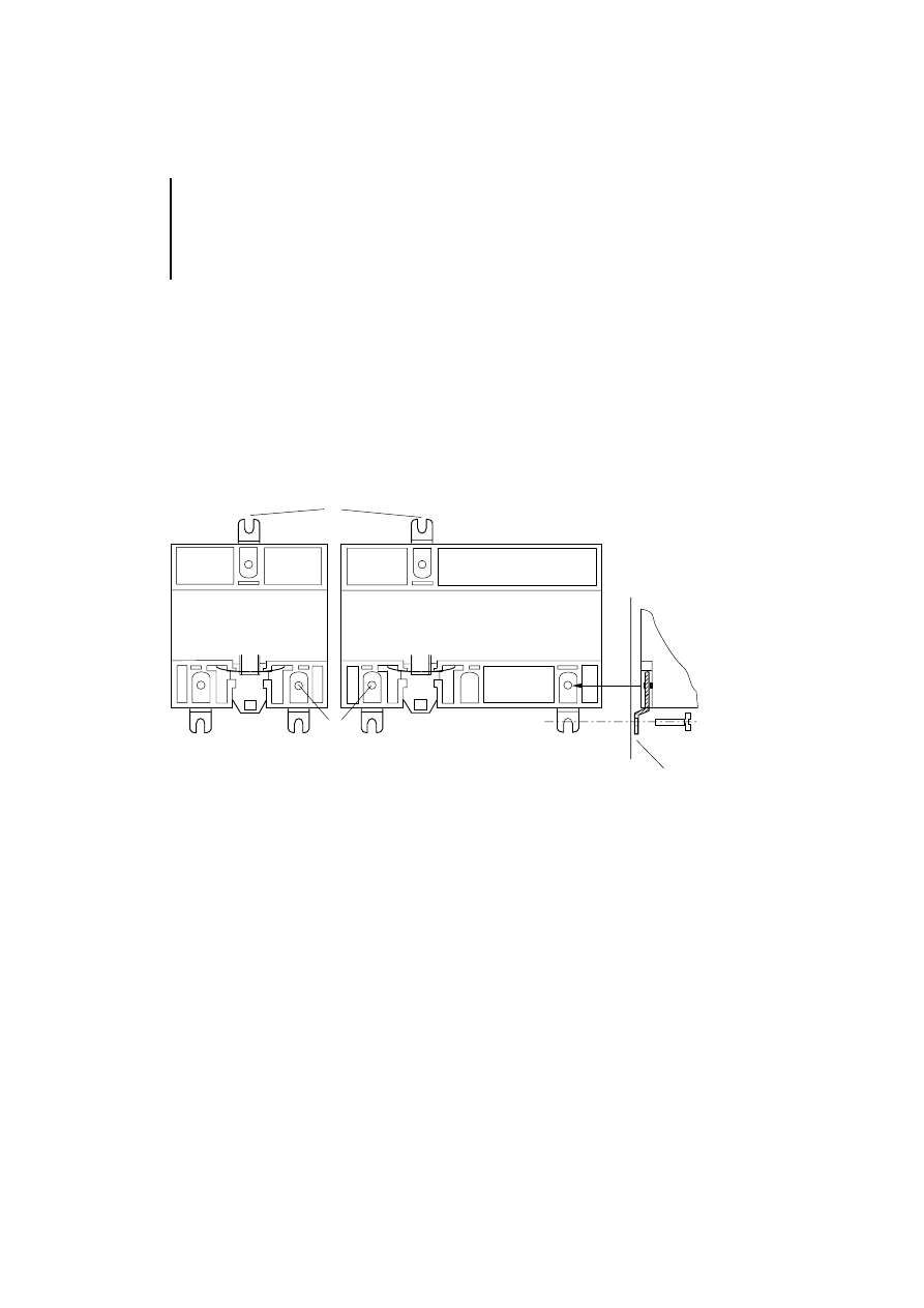
Mounting on mounting
plate via fixing feet
왘 Turn over the module. Here you will see the slots
provided for the fixing feet
햲
on the back of the
module.
왘 Push the fixing feet into the slots until the lugs
햳
snap into position.
왘 Ensure that all fixing feet are snapped securely
into position.
왘 Fasten each fixing foot to the mounting plate
햴
using an M4 screw.
Figure 3: Mounting on mounting plate
햲
햴
LE 4 -...
EM 4 -... / PS 4-...
햳
햳
Installing in the control
cabinet
9
09/99 AWB 2700-1331 GB
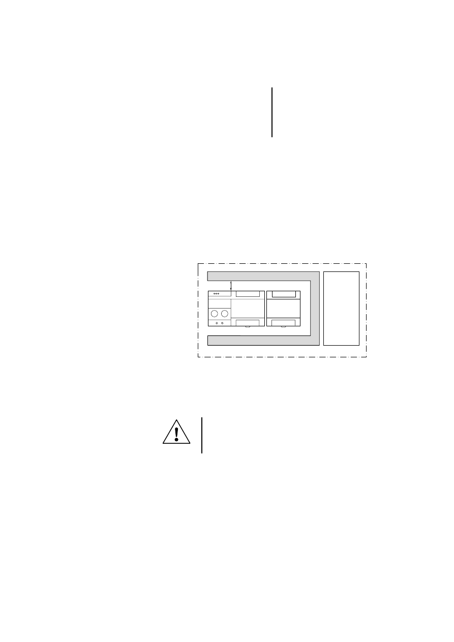
Installing in the control
cabinet
Ensure the following points when installing in a
control cabinet:
왘 Fasten the modules horizontally in the control
cabinet.
Proceed as follows to prevent electromagnetic
interference from impairing the function of the
electronic control section:
왘 Ensure a spacing between the cable duct
햲
and
the module of at least 5 cm (2").
왘 Keep the control
햴
and power sections
햳
apart.
Figure 4: Arrangement in the control cabinet
Fitting/removing the
terminal strip
햲
햴
50
햳
Caution!
Electrostatic charge can destroy the equipment.
Make sure you are free of electrostatic charge
before working on the input/output terminals.
Mounting
10
09/99 AWB 2700-1331 GB
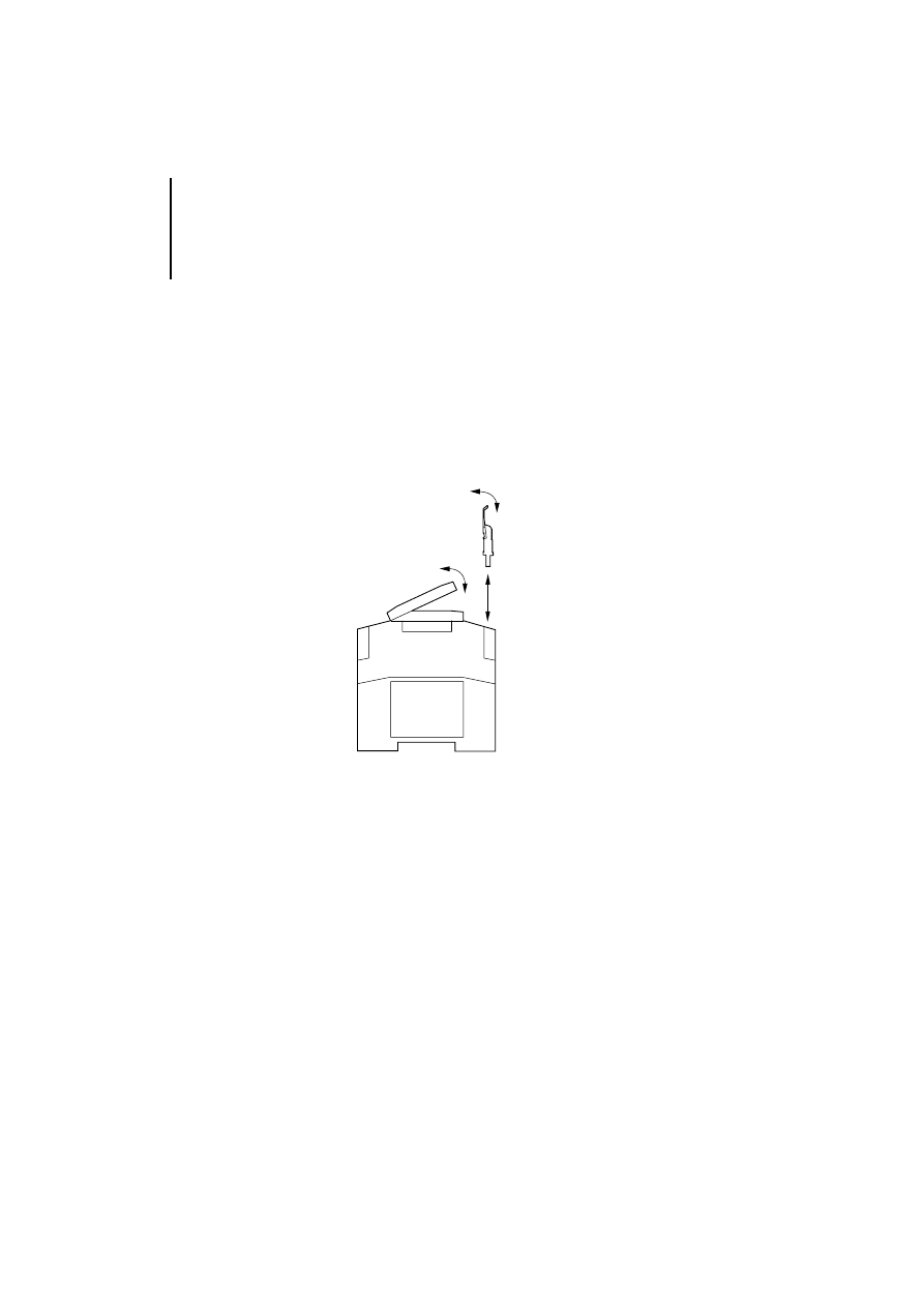
If you wish to pre-wire a circuit or change a module,
you can remove the plug-in screw terminal from the
module.
왘 Open out fully the cover of the plug-in screw
terminal.
왘 Remove the plug-in screw terminal at its cover.
왘 Use the same procedure for the other plug-in
screw terminal.
Figure 5: Fitting/removing the plug-in screw terminal
Proceed as follows to fit the plug-in screw terminal
into the module:
왘 Open out fully the cover of the plug-in screw
terminal.
왘 Fit the plug-in screw terminal into the slot and
press it into position.

11
09/99 AWB 2700-1331 GB
3
Engineering
Electromagnetic
compatibility (EMC)
The following engineering measures must be
observed in order to meet the requirements of the
EMC regulations and comply with the following
European EMC standards:
EN 50 081-2 (Emission)
EN 50 082-2 (Immunity)
Other engineering instructions are given in the
manual “EMC Guidelines for Automation
Systems”, AWB 27-1287-GB and the EMC
manual Electromagnetic Compatibility of
Machines TB 02-022 GB.
Engineering
12
09/99 AWB 2700-1331 GB
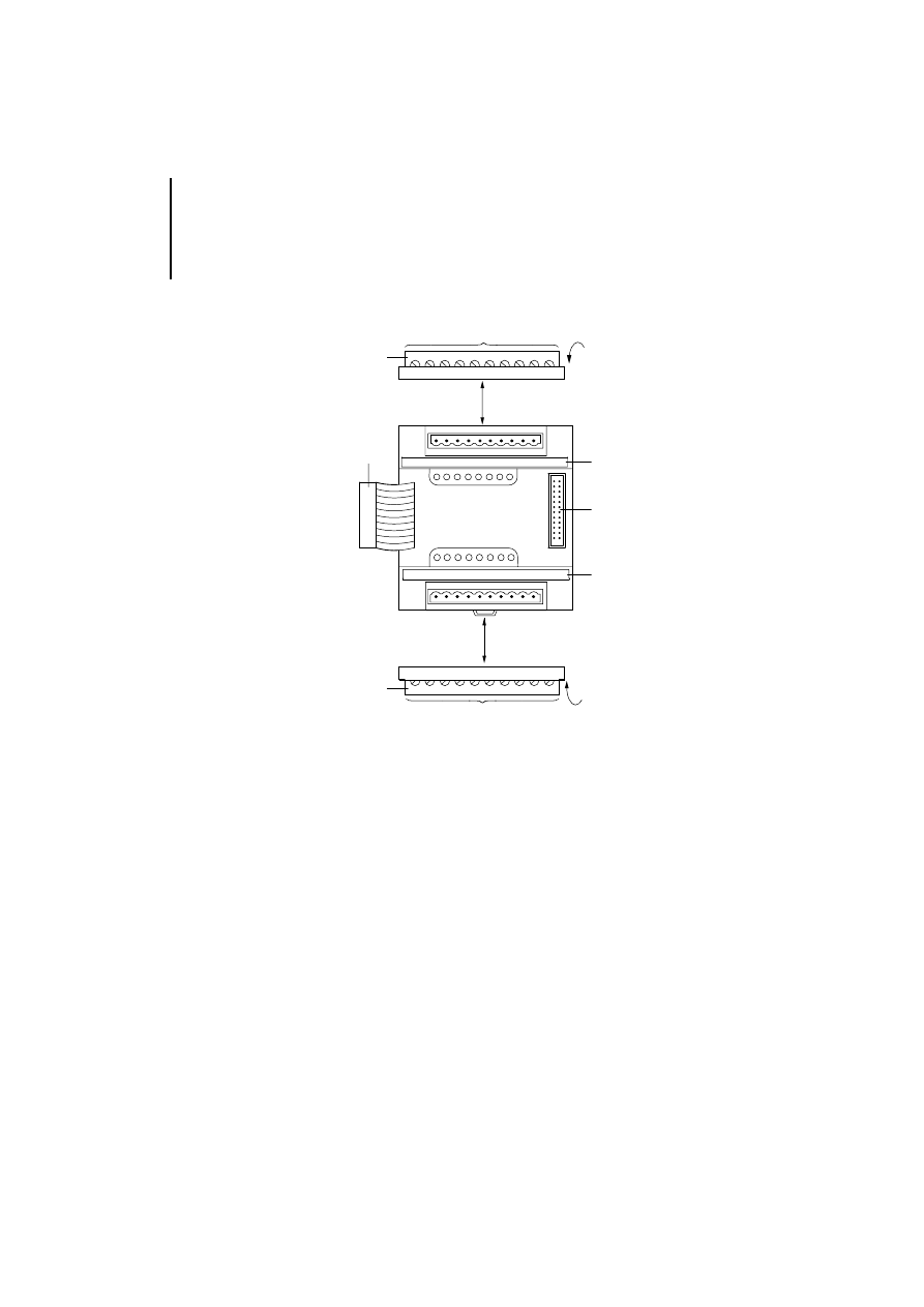
Connection overview
Figure 6: Connection overview
햲 Socket connector
햳 Plug-in screw terminal
햴 Connection cross-sections:
flexible with ferrule 0.22 to 1.5 mm
2
(AWG 23 to AWG 16)
solid 0.22 to 2.5 mm
2
(AWG 23 to AWG 13)
햵 Designation strips
햶 Connector strip
햵
햶
햲
햳
햴
햳
햴
햵
0V
A
I
0
I
1
0V
A
0V
A
I
0
I
1
0V
A
0V
A
I
2
I
3
0V
A
Connecting to the
PS 4-200/300,
EM 4-204-DX1
13
09/99 AWB 2700-1331 GB
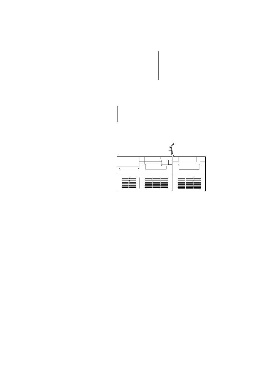
Connecting to the
PS 4-200/300,
EM 4-204-DX1
왘 Connect the LE 4-206-AA2 to the PS 4-200/300,
EM 4-204-DX1 via the plug connector.
Figure 7: Connecting to the PS 4-200/300, EM 4-204-DX1
The LE 4-206-AA2 must be mounted on the top-
hat rail or fastened to the mounting plate before
connecting it to the 4-200/300, EM 4-204-DX1.
Engineering
14
09/99 AWB 2700-1331 GB
Connecting analog
cables
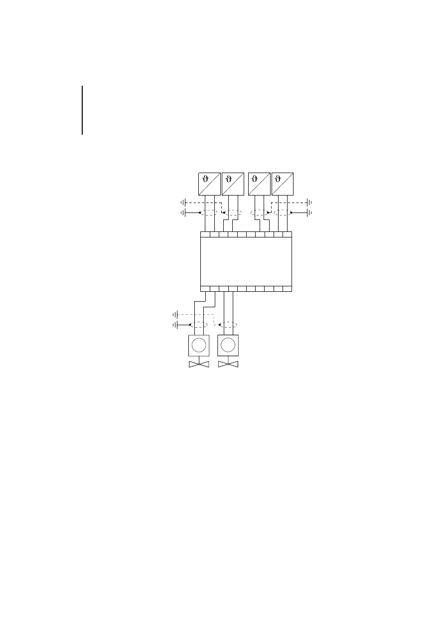
The following example shows the connection of the
analog cables to the LE 4-206-AA2:
Figure 8: Connecting the analog cables
햲 Screening of the analog cables (see Figure 9)
햳 Connection for sensors
햴 Connection for actuators
Analog
Output
M
A
0V
0
I
1
I
A
0V
A
0V
2
I
3
I
A
0V
A
0V
0
I
1
I
A
0V
Analog
Input
LE 4-206-AA2
햲
0(4) –
20 mA
햳
햴
0(4) –
20 mA
0(4) –
20 mA
0(4) –
20 mA
M

Grounding the analog
cables
15
09/99 AWB 2700-1331 GB
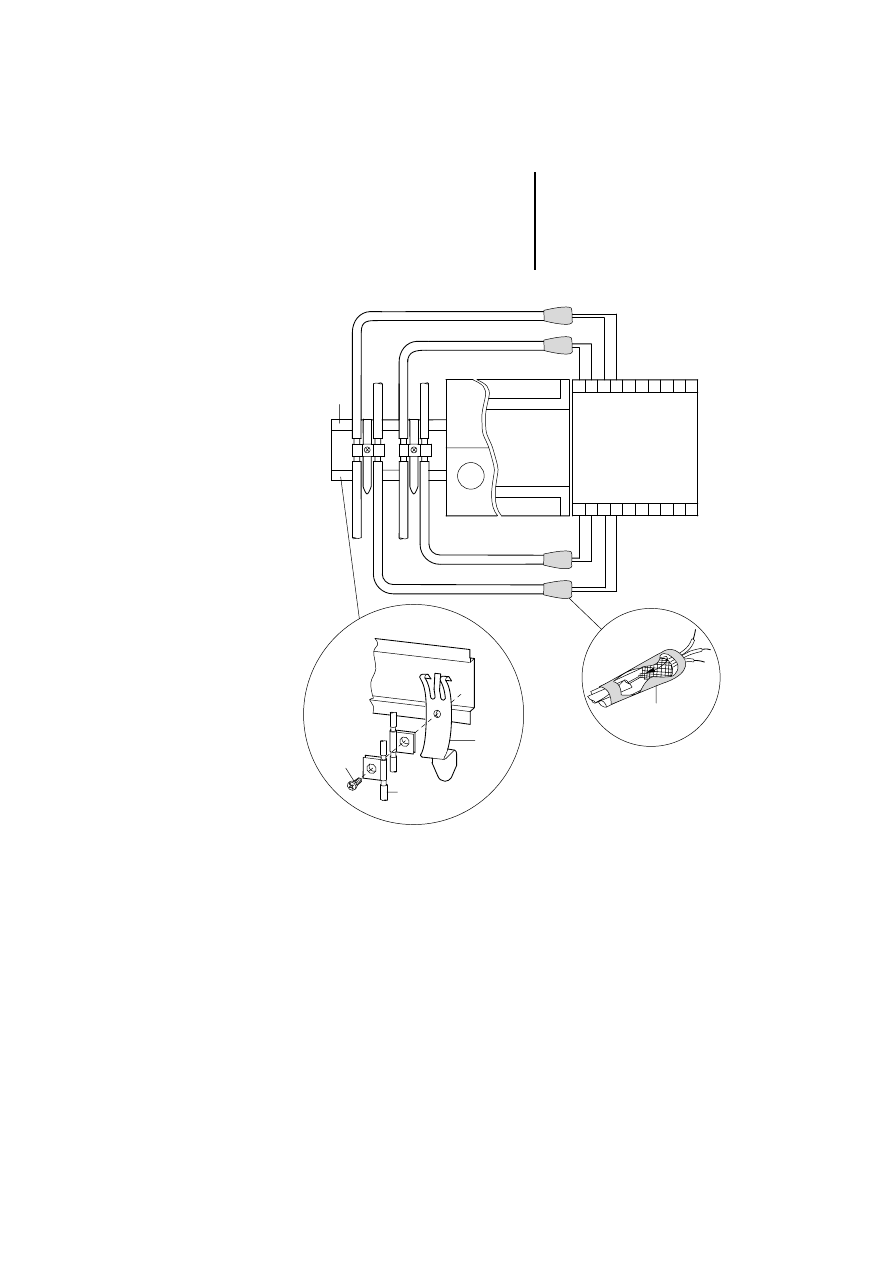
Grounding the analog
cables
Only use screened cables for analog lines (see
Figure 9).
왘 Strip the cable sheathing near the contact clip 햵
왘 Fit a contact clip on the bared part of the analog
cables.
왘 Make a low impedance connection between the
contact clip and the ground potential, such as the
terminal clip
햴, on the top-hat rail.
왘 Ensure that all connections are corrosion proof
and that the paint is removed from the connection
point of mounting plates.
왘 Pull back the screen at the ends of the analog
input cables.
왘 Isolate the screen with suitable material such as
heat shrinkable tubing
햳.
왘 Ground the top-hat rail with a large contact area.
Note!
Electromagnetic interference
Interference and line-conducted interference
according to ENV 50 140 and ENV 50 141 can
corrupt your measuring result by up to 20 %.
A faulty connection of the module may produce
interference for other components.

Engineering
16
09/99 AWB 2700-1331 GB
Legend for Figure 9
햲 Top-hat rail
햳 Heat shrinkable tubing
햴 Terminal clip
햵 Contact clip
햶 Screw
Items
햴, 햵 and 햶 are part of the ZB 4-102-KS1
screen grounding kit. This grounding kit must be
ordered separately.
Grounding the analog
cables
17
09/99 AWB 2700-1331 GB
Figure 9: Grounding the screen for analog cables
햴
햵
햶
Analog
Input
0
I
1
0 V
A
I
0 V
A
2
I
3
0 V
A
I
0 V
A
0
I
1
0 V
A
I
0 V
A
Analog
Output
LE 4-206-AA2
PS 4-201-MM1
햲
햳

18
09/99 AWB 2700-1331 GB

19
09/99 AWB 2700-1331 GB
4
Configuration and Parameter Setting
The LE 4-206-AA2 is configured in the topology
configurator of the Sucosoft S 40 programming
software:
왘 Open the Topology configurator and choose
‹Edit ➞ Local Expansion›.
왘 Select the LE 4-206-AA2 from the device list.
When selected the LE 4 will be highlighted.
왘 Choose ‹Edit ➞ Parameters› and set the input
and output parameters of the device.
Setting the input and
output parameters
The input and output parameters can be set to meet
the requirements of the application at hand. The
following parameters can be set:
Averaging (only for input channels)
Value range of the input/output current for each
channel
Scaling of inputs and outputs for each channel
The fastest refresh time for all I/O is achieved if
Averaging and Scaling are not selected. Without
these, the refresh time is approx. 3 ms including the
basic filter process. If Scaling is activated without
Averaging, the time required is 4 ms.
Factory setting:
No averaging
Value range 0 to 20 mA
No scaling

Configuration and
Parameter Setting
20
09/99 AWB 2700-1331 GB
Averaging
This setting applies to all the inputs.
The averaging result depends on the scan interval
and the number of mean values used. The scan
interval is the time in which all analog input values are
to be scanned and supplied to the PLC.
The averaging result depends on the selected
number of values and the scan interval. These two
parameters determine the time required for
averaging:
Example:
The different combinations and the time required for
averaging are set in the Sucosoft S 40 Parameter
Editor.
The table shows some combinations of scan interval
and number of values to form the average.
If the input changes from 0 to 20 mA, the final digital
value will be reached in 6 times the time required for
forming the averaging value.
Scan interval
3
3
3
3 Number of averaged values = Averaging time
4 ms
3 8 = 32 ms
Number of averaged
values
Scan/refresh
interval [ms]
Averaging [ms]
2
4
8
4
4
16
8
4
32
16
4
64
16
16
256
16
62.5
1000

Setting the input and
output parameters
21
09/99 AWB 2700-1331 GB
The outputs are also refreshed within the scan
interval for the inputs. In other words, the input scan
interval is at the same time the refresh interval for the
outputs.
Selecting a low scan interval and a small number of
values ensures a fast response in digital output value
to changes in the analog input signal. This will cause
a slight oscillation of value. To avoid oscillations
choose a larger scan interval with a large number of
values.
Value range of the input/output current
The value range for each input and output can be set
separately. Ranges of 0 to 20 mA (0 to 4095) and 4 to
20 mA (820 to 4095) can be selected.
Scaling the inputs and outputs
Scaling can be selected irrespective of whether
Averaging has been selected or not. This option
allows you to assign each input and output signal
from 0(4) to 20 mA a specified range of values for the
application concerned. The range is defined by
means of a minimum and maximum limit value.
If Scaling has been selected, enter the minimum and
maximum value required in the measuring range
window. The following limit values are possible
absolute max. limit value: +32767
absolute min. limit value: –32768
Further information is provided in the chapter Analog
Value Display

Configuration and
Parameter Setting
22
09/99 AWB 2700-1331 GB
Setting parameters for
the PROFIBUS-DP
network
To use LE 4-206-AA2 as a local expansion module
for the EM 4-204-DX1, the Averaging and Value
Range parameters must be set in the CFG
Configurator.
Scaling
If the LE 4-206-AA2 is connected to PROFIBUS-DP
via the EM 4-204-DX1, scaling applies to all channels.
If Scaling has been selected, enter the minimum and
maximum value required in the measuring range
window. The following limit values are possible
absolute min. limit value –32768
absolute max. limit value: +32767
Since the PROFIBUS-DP standard only permits
positive values between 0 and 65535, the negative
limit value must be converted with the following
formula (twos' complement of the positive value:
Example of a negative limit value:
Enter the range from –120 to +130. Set the following
parameters:
min. limit value: 65536 – 120 = 65416
max. limit value: 130
Example of a positive limit value:
Enter the range from 0 to +100. Set the following
parameters:
min. limit value: 0
max. limit value: 100
Ensure the following: min. limit value < max. limit
value.
An incorrect entry will cause the output of 0 or
4 mA
655366 – negative number = Parameter number

23
09/99 AWB 2700-1331 GB
5
Addressing/Operation/Diagnostics
Addressing
Addressing the inputs and outputs of the LE 4-206-
AA2 is described in the “Hardware and Engineering”
manual of the master in use. The data type of the
analog values is always of “Integer”. The operands
are addressed as follows:
VAR
AnaInp AT%IAW0.0.x.y:INT; (*Input scan*)
AnaOutp AT%QAW0.0.x.y:INT; (*Address output*)
END_VAR
LD AnaInp
ST AnaOutp
x = 1, 2:
Module number
y = 0, 2, 4, 6: I/O number
Input designation
Input number
Operand
I
0
0
IAW0.0.x.0
I
1
2
IAW0.0.x.2
I
2
4
IAW0.0.x.4
I
3
6
IAW0.0.x.6
Output designation
Output number
Operand
I
0
0
QAW0.0.x.0
I
1
2
QAW0.0.x.2

Addressing/Operation/
Diagnostics
24
09/99 AWB 2700-1331 GB
Operation
Startup behaviour
Once the power supply has been switched on, the
PLC sends the parameters set by the user to the
LE 4-206-AA2 and starts the exchange of process
data. No process data is exchanged if the PLC is in
HALT after being switched on. All the outputs of the
LE 4-206-AA2 will remain at 0 mA.
HALT/RUN changeover
Startup behaviour depends on the following.
LE parameters set beforehand
The parameters are transferred with the program. In
this case, the LE requires about 500 ms to adapt the
parameters. The I/O values can then be transferred.
During the calculation period, diagnostics bit 2 is set
in diagnostics byte 1. The Local Status (DLS)
diagnostics bit in the diagnostics status word of the
PS 4 is not set.
In order to ensure that the user program only sends
and receives plausible values, structure the program
so that the scanning and transfer of values is
controlled by the diagnostics bit.
Existing parameters in the LE:
When the PLC switches from Halt to Run,
communication with the LE 4-206-AA2 is resumed
immediately.

Diagnostics
25
09/99 AWB 2700-1331 GB
RUN/HALT changeover
When the PLC changes from RUN to Halt the PLC
continues to scan the input signals and saves them
in its internal memory. This means the plausible
values are available as soon as the PLC is restarted.
Otherwise, with a long scan time selected, the
averaging process would require several minutes to
provide values within range of the recorded signal.
If the PLC is in Halt, the output currents are restricted
to the selected value range accordingly.
Diagnostics
The diagnostics data of the LE 4-206-AA2 is stored
in two diagnostics bytes. The first bytes contains all
signals relating to correct functioning and a general
signal for out-of-range values or wire breakage on an
input.
The second diagnostics byte determines on which
input the wire breakage or out-of-range value has
occurred.
Value range
Output current
0 to 20 mA
0 mA
4 to 20 mA
4 mA

Addressing/Operation/
Diagnostics
26
09/99 AWB 2700-1331 GB
Diagnostics byte 1
Out-of range values
An out-of-range value is indicated if the current value
is 5 % higher than the maximum input current of
20 mA or is in the negative range
^ –1 mA.
Wire breakage
A wire breakage can only be detected if the value
range for the input is 4 to 20 mA. An error signal will
be output if the current falls below 3 mA.
Further information is provided in the chapter
“Analog Value Processing”
Structure of the first diagnostics byte:
Bit
7
6
5
4
3
2
1
0
Bit 0 = 0:
1:
ok
no/incorrect module
Bit 1 = 0:
1:
ok
wire breakage/out-of-range value
Bit 2 = 0:
1:
ok
Impermissible value
Bit 3 = 0:
1:
ok
Time monitoring
Bit 4 to 7: not assigned

Diagnostics
27
09/99 AWB 2700-1331 GB
No/incorrect module (Bit 0)
(No/unexpected module)
No or incorrect local expansion module.
Check
whether the type of local expansion module is
correct,
whether the LE bus connection is properly fitted.
Replace the faulty local expansion modules.
The signal is cleared automatically once the fault is
rectified. A reset in the diagnostics status of the CPU
is not necessary.
Wire breakage/out-of-range value (Bit 1)
The module measuring channel has detected a wire
breakage in the sensor or the measured value at the
channel specified is out of range.
If necessary, more detailed troubleshooting for the
sensor concerned is possible using the measured
values available. Call the Display/Force I/O window
for this station.
The signal is cleared automatically once the fault is
rectified.
Values not valid (Bit 2)
The local expansion module will make an internal
parameter setting after power is restored; analog
values that have been read or written are invalid for
this time. Permissible values can be read or output as
soon as the signal is cleared automatically.
A reset in the diagnostics status of the CPU is not
necessary.

Addressing/Operation/
Diagnostics
28
09/99 AWB 2700-1331 GB
Time monitoring (Bit 3)
(Timeout)
The LE 4-206-AA2 is not reporting its presence. This
may be due to a hardware error. Try to restart the
system by switching it off and then on again. Replace
a faulty module.
The signal is cleared automatically once the fault is
rectified. A reset in the diagnostics status of the CPU
is not necessary.
Scanning
Diagnostics byte 1 is scanned in bit or byte format
with the following syntax:
The variable declaration has not been shown
here. Refer to the manual Language Elements for
PS 4/PS 416 (AWB 2700-1306 GB) for a general
declaration.
Bit format
Byte format
LD %ISB0.0.x.0.y
LD %ISB0.0.x.0
x = 1 or 2 (module number)
y = 0 to 7 (bit number)

Diagnostics
29
09/99 AWB 2700-1331 GB
Diagnostics byte 2
Structure of the second diagnostics byte:
Bit 0 to 3:
Wire breakage inputI
x
Bit 4 to 7:
Out-of-range value input I
x
Wire breakage input I
x
(Wire breakage input x)
Wire breakage on the measuring channel indicated.
The signal is cleared automatically once the fault is
rectified.
Out-of-range value input I
x
The measured value on the measuring channel
indicated out-of-range.
The signal is cleared automatically once the fault is
rectified.
Scanning
Diagnostics byte 2 is scanned in bit or byte format
with the following syntax:
Bit
7
6
5
4
3
2
1
0
Bit format
Byte format
LD %ISB0.0.x.1.y
LD %ISB0.0.x.1
x = 1 or 2 (module number)
y = 0 to 7 (bit number)

Addressing/Operation/
Diagnostics
30
09/99 AWB 2700-1331 GB
Diagnostics for the
PROFIBUS-DP network
The LE 4-206-AA2 can be used as a local expansion
for the EM 4-204-DX1 in a PROFIBUS-DP line.
A detailed description of the diagnostics on the
PROFIBUS-DP line is provided in the the Hardware
and Engineering manual of the EM 4-204-DX1
(AWB 27-1315 GB) and in the manuals of the
masters used.
The scanning and evaluation of the diagnostics bytes
for the PS 416-NET-440 master card are described
in the Hardware and Engineering manual
(AWB 2700-1330 GB).
Scanning the diagnostics bytes with operations such
as LD%ISB1.2.1.0, as used for Sucosoft-K-stations,
is not possible with PROFIBUS-DP. An error
message will be output if this instruction is present.
The diagnostics byte of the LE 4-206-AA2
contains a central signal for wire breakage and
out-of-range errors.
31
09/99 AWB 2700-1331 GB
6
Analog Value Representation
Analog/digital
conversion
The LE 4-206-AA2 converts analog input signals to
12-bit digital values and vice versa. The basic digital
range of values is represented from 0 to 4095 dec or
0 to FFF hex (12 bit).
Figure 10: Analog/digital conversion
Calculation example
In order to calculate the digital or analog value the
step width must first be defined.
19.99
4
0
mA
820
4095
0
0
334
0FFF
dec.
hex

Analog Value
Representation
32
09/99 AWB 2700-1331 GB
Calculating the step width:
The digital value will change by one bit if there is a
change in the analog input value of 0.00488 mA
(increment).
Calculating the analog value
The analog value equivalent of a digital value x =
2048 is calculated as follows:
Example:
Calculating the digital value
The digital value equivalent of an analog value y = 5
mA is calculated as follows:
Example:
(the value shown is 1024)
Upper
lower meas. limit
–
2
12
---------------------------------------------------------------------
20 mA
4096
-----------------
0.00488 mA
=
=
x
3 Step widte Analog value
=
2048
3 0.00488 9.99 mA
=
y
Step width
----------------------------
Digital value
=
5
0.00488
---------------------
1024.6
=
Analog/digital conversion
33
09/99 AWB 2700-1331 GB
Value range of inputs
Inputs for 0 to 20 mA
Figure 11: Value range for current inputs 0 to 20 mA
If the input current goes over 20 mA, the maximum
value of the value range will normally be shown. This
is the value 4095 in the unscaled range and the
specified upper limit in the scaled range.
If the input current is negative because the cables
have been reversed, the measured value will be “0”.
If I
^ 21 mA or I ^ –1 mA due to reversed poles, the
diagnostics bit "Out-of-range" diagnostics bit will
indicate an out-of-range value (see page 26).
mA
21
19.99
15
10
5
0
400
800
C00
FFF
1024
2048
3072
4095
hex
dec.
Analog Value
Representation
34
09/99 AWB 2700-1331 GB
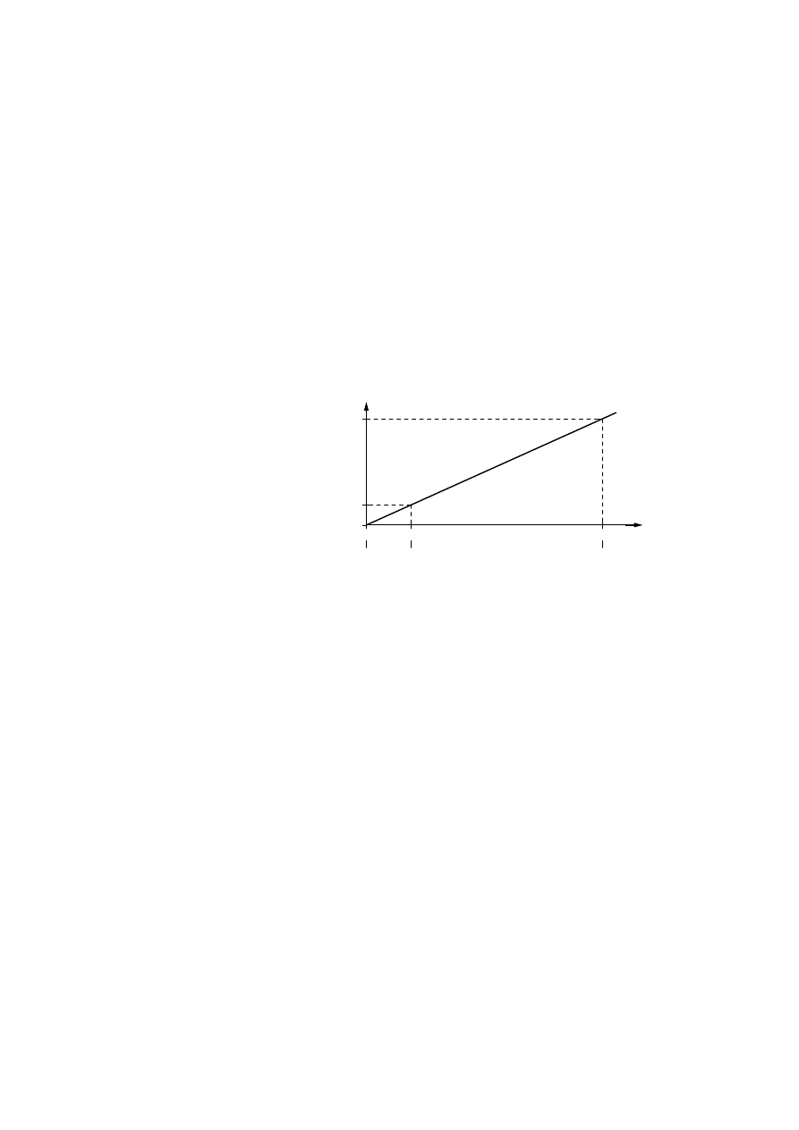
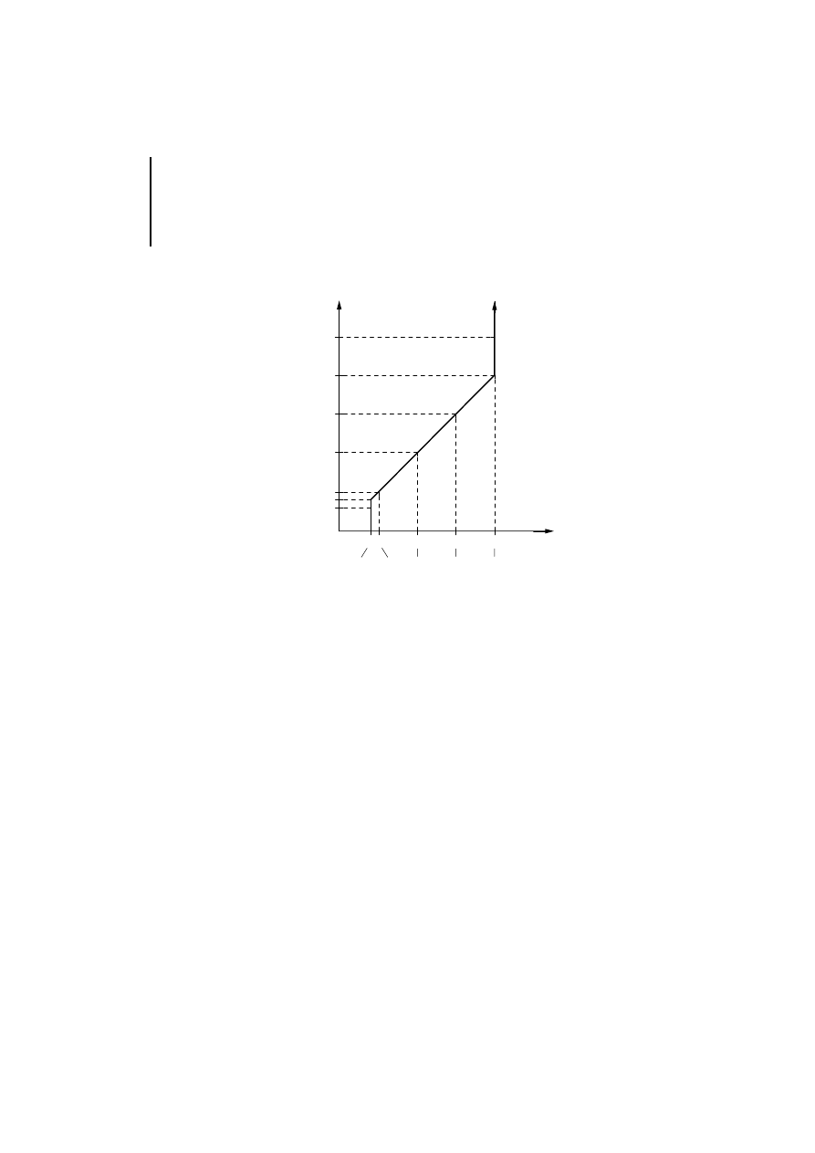
Inputs for 4 to 20 mA
Figure 12: Value range for current inputs 4 to 20 mA
If the input current exceeds 20 mA, the maximum
value of the value range will normally be output. This
is the value 4095 in the unscaled range and the
specified upper limit in the scaled range.
A current of 4 mA will cause the value 820 (334 hex)
to be output in the unscaled range and the lower limit
value in the scaled range.
If the input current drops below 4 mA or is negative
due to the reversing of the cables, the value 820
(334 hex) will be output as a constant or the lower
limit value will be shown if the range is scaled.
mA
21
19.99
15
10
5
, 4
3
334 400
800
C00
FFF
1024
2048
3072
4095
820
0
hex
dec.

Analog/digital conversion
35
09/99 AWB 2700-1331 GB
Two error messages may be output with inputs
configured with a measuring range of 4 to 20 mA:
With out-of-range values of
^ 21 mA or ^ –1 mA
the "Out-of-range value” diagnostics bit will
change to “1” (see page 26). The input current
can be negative if the cables are reversed.
In the event of a wire breakage with values
% 3 mA the "Wire breakage" diagnostics bit will
change to “1” (see page 26).
Output value range
If faulty entries cause the output of values outside of
the permissible range, the appropriate maximum of
minimum value will be output.
Analog Value
Representation
36
09/99 AWB 2700-1331 GB
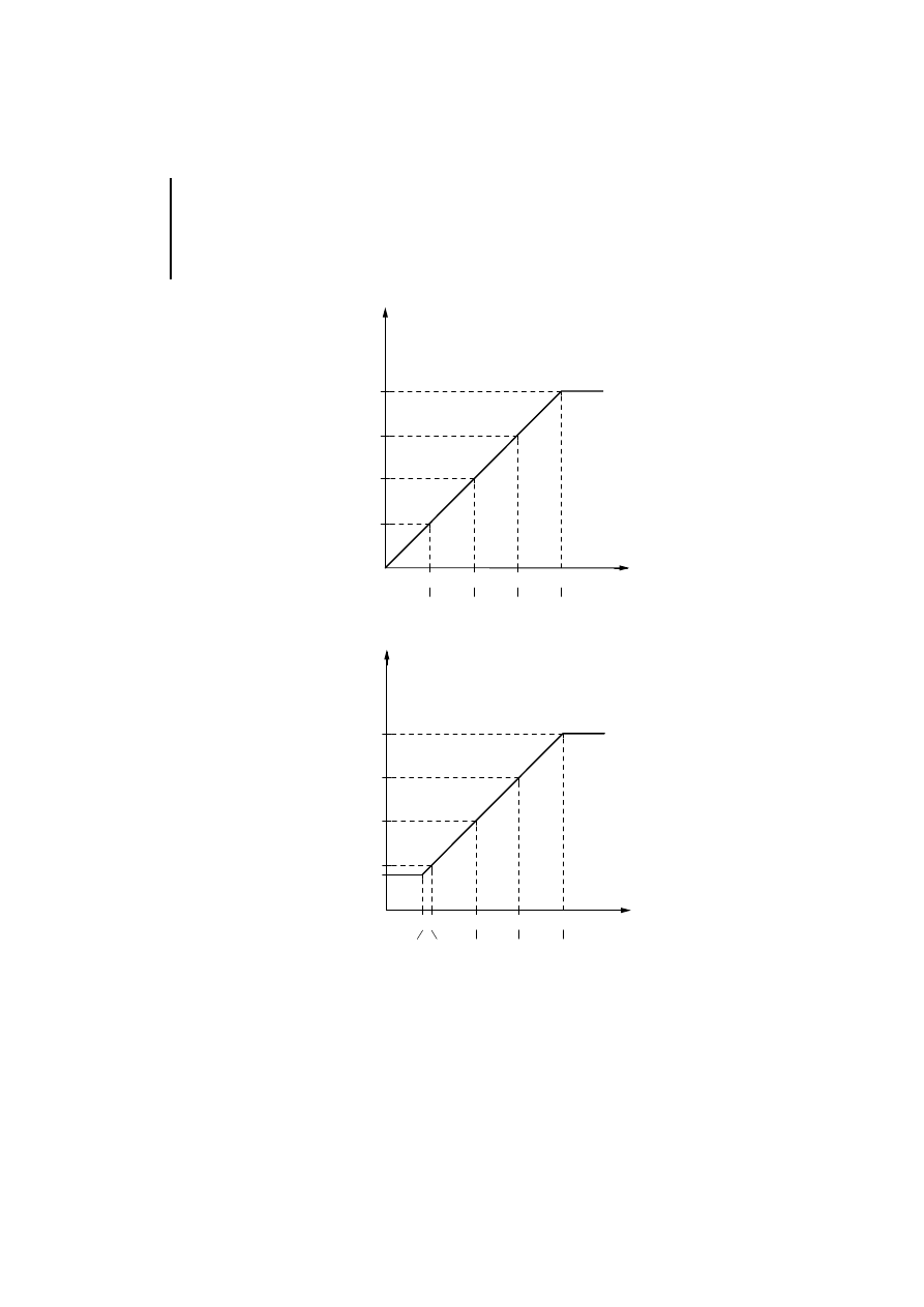
Figure 13: Value range for current outputs 0 to 20 mA
Figure 14: Value range for current outputs 4 to 20 mA
mA
19.99
15
10
5
400
800
C00
FFF
1024
2048
3072
4095
0
hex
dec.
mA
19.99
15
10
5
0
800
C00
FFF
2048
3072
4095
334 400
1024
820
4
hex
dec.
Analog/digital conversion
37
09/99 AWB 2700-1331 GB
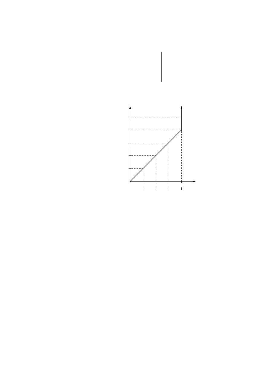
Scaling
A scaled range can be assigned to the the digital
value range. This allows the specific value for the
application to be scanned or output directly.
The scaled values are based on the value range from
0 to 4095 with an input/output current of 0 to
19.99 mA or from 820 to 4095 with a current of 4 to
19.99 mA.
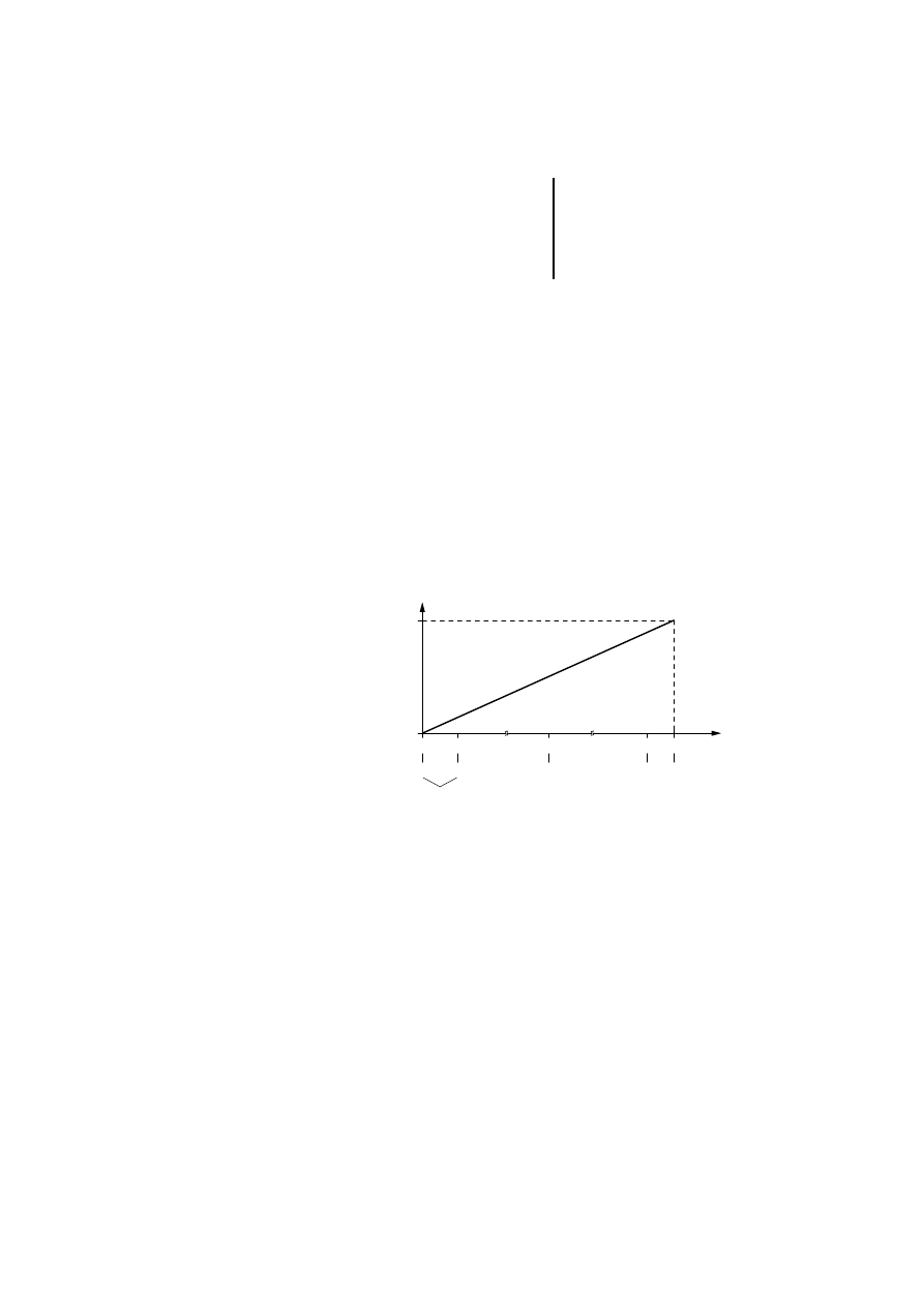
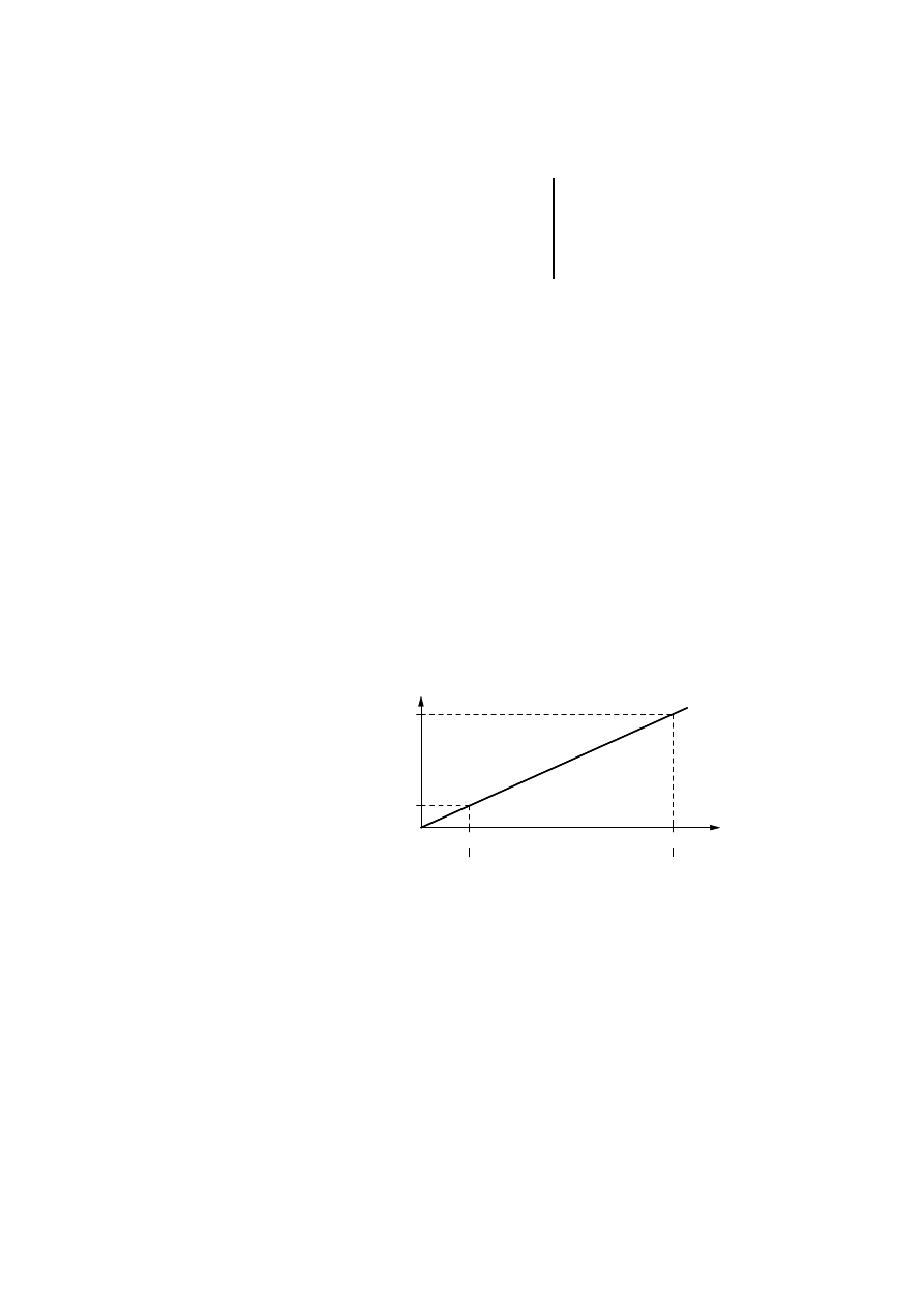
If, for example, a scaled range from –32768 to 32767
was selected for the input signal 0 to 19.99 mA, the
scaled range will be divided into steps of 16.
Example:
Figure 15: Scaling the input signal
65535
4095
----------------
16
=
19.99
mA
4095
0
1
– 32768
2048
0
0
– 32752
4094
32751 32767
Difference: 16
decimal value
scaled value
Analog Value
Representation
38
09/99 AWB 2700-1331 GB
The following examples show the scaling from 0 to
200 with an input value of 0 to 20 mA and 4 to 20 mA.
The maximum scaled range can be defined from
–32768 to +32767.
The difference between the higher and lower value
must be at least “1”.
The higher value must always be "more positive"
than the lower one.
Examples:
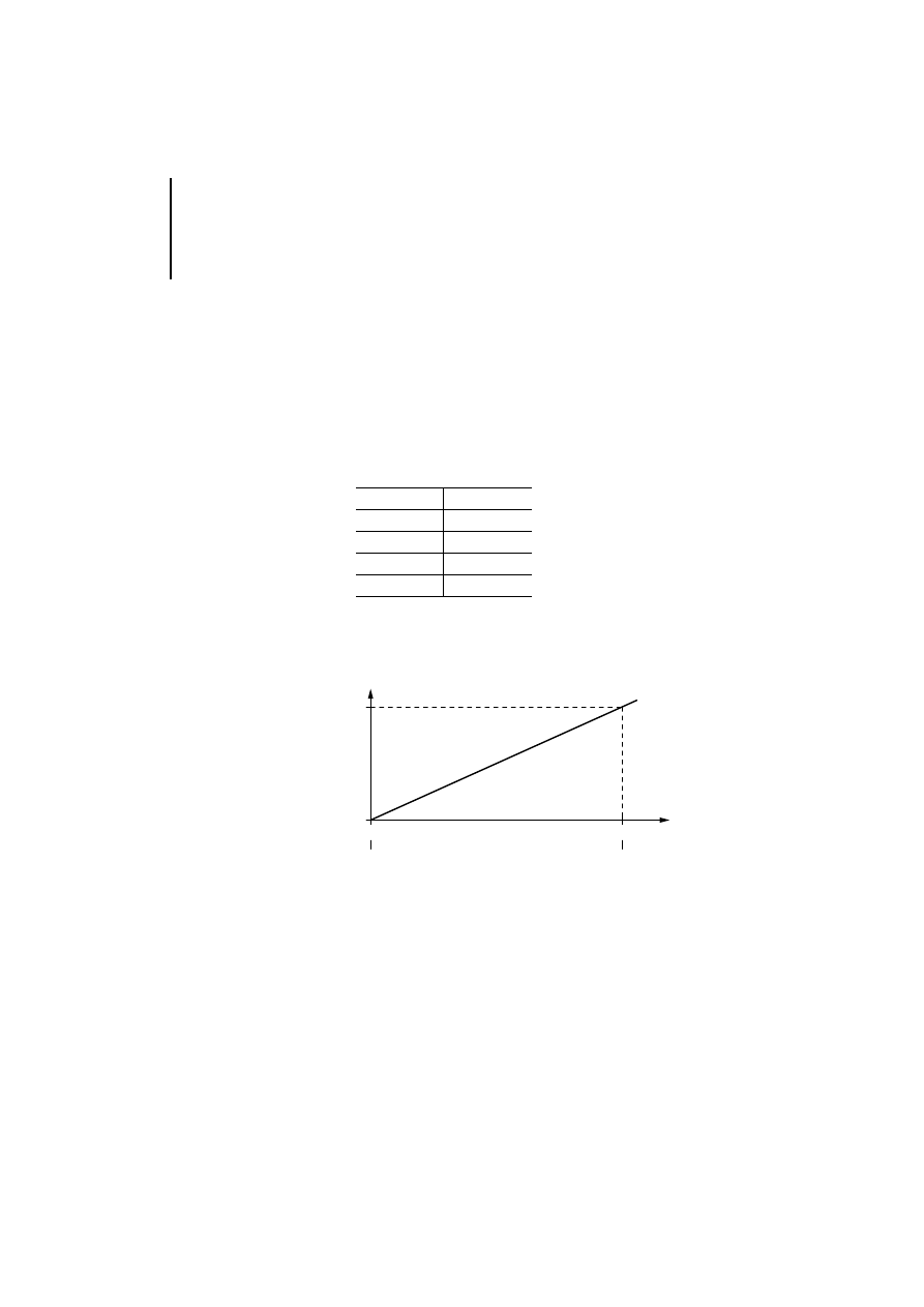
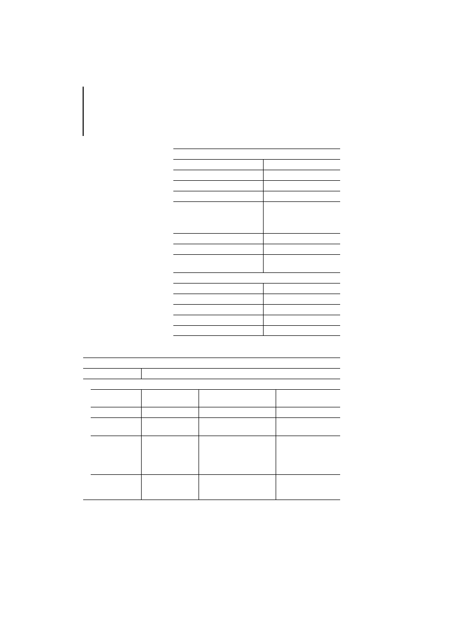
Example 1:
Scaling of value range 0 to 4095. In this example “0”
was used for the lower value and 200 for the higher.
Figure 16: Scaling the input signal 0 to 19.99 mA from
0 to 200
Lower value
Higher value
–1
0
0
1
2
3
–16
4
19.99
mA
4095
0
0
0
200
decimal value
scaled value
Analog/digital conversion
39
09/99 AWB 2700-1331 GB
Calculating the analog value
y = Required analog value
B = Selected range, 0 to 200 = 200
z = Specified digital value (0 to 200)
Calculating the digital value
x = Required digital value (0 to 200)
B = Selected range, 0 to 200 = 200
v = Specified analog value
Example 2:
Scaling of value range 820 to 4095. In this example
“0” was used for the lower value and 200 for the
higher.
Figure 17: Scaling the input signal 4 to 19.99 mA from
0 to 200
z
3 4096 3 0.00488
B
--------------------------------------------------------
y [mA]
=
v
3 B
0.00488
3 4096
--------------------------------------------
x
=
19.99
mA
4095
0
200
0
4
19.99
mA
4095
0
820
200
0
4
decimal value
scaled value

Analog Value
Representation
40
09/99 AWB 2700-1331 GB
Calculating the analog value
y = Required analog value
B = Selected range, 0 to 200 = 200
z = Specified digital value (0 to 200)
Calculating the digital value
x = Required digital value (0 to 200)
B = Selected range, 0 to 200 = 200
v = Specified analog value
The digital values are shown in 16-bit format.
Positive values: 0 to 7FFF
Negative values: 8000 to FFFF
decimal
hexadecimal
0
0000
1
0001
.
.
.
.
.
.
32767
7FFF
–32768
8000
.
.
.
.
.
.
–2
FFFE
–1
FFFF
z
3 0.00488 3 3276
B
--------------------------------------------------------
4
+
y [mA]
=
(v
4)
–
3 B
3276
30.00488
----------------------------------------
x
=

41
09/99 AWB 2700-1331 GB
Appendix
Technical Data
General
Standards, regulations
EN 61 131-2, EN 50 178
Ambient temperature
0 to 55 °C
Storage temperature
–25 to +70 °C
Weight
approx. 300 g
Shock resistance
15 g, 11 ms
Vibration resistance
Const. constant 1 g, f = 0 to
150 Hz
Device mounting
Snap-fit on top-hat rail or
mounting plate
Rated insulation voltage
600 V AC
Degree of protection
IP 20
Terminals
Plug-in screw terminal
Terminal cross-section
Flexible with ferrule
0.22 to 1.5 mm
2
(AWG 23 to 16)
solid
0.22 to 2.5 mm
2
(AWG 23 to 13)
Configuration
With expandable PS 4 compact
PLCs
Max. number per PS 4-200/300,
EM 4-204-DX1
2
Isolation
Between LE bus and analog I/O
Yes
Insulation between I/O
no
Cable to sensors or actuators
Screened twisted pair
cable
Appendix
42
09/99 AWB 2700-1331 GB
Inputs
Number of current inputs
4
Measuring ranges
0 to 20 mA, 4 to 20 mA
Resolution
12 Bit
Total error
Normally 0.4 % (0 to 55 °C)
Scanning
Without averaging,
without scaling 3 ms
without averaging,
with scaling 4 ms
Averaging
yes, from 8 ms to 1 s
Input impedance
50
V
Error signals
Wire breakage
out-of-range value
Outputs
Number of current outputs
2
Measuring ranges
0 to 20 mA, 4 to 20 mA
Resolution
12 Bit
Total error
Normally 0.4 % (0 to 55 °C)
Load resistance
max. 500
V
General EMC specifications for automation equipment
Emission
EN 55 011/22 Class A
Interference immunity
ESD
EN 61 000-4-2
Contact discharge
Air discharge
4 kV
8 kV
RFI
EN 61 000-4-3
AM/PM
10 V/m
Burst
EN 61 000-4-4
Mains/digital I/O
Analog I/O, fieldbus
2 kV
1 kV
Surge
EN 61 000-4-5
Digital I/O, asymmetrical
Mains DC, asymmetrical
Mains DC, symmetrical
Mains AC, asymmetrical
Mains AC, symmetrical
0.5 kV
1 kV
0.5 kV
2 kV
1 kV
Immunity to line-
conducted
interference
EN 61 000-4-6
AM
10 V

43
09/99 AWB 2700-1331 GB
Index
A
Analog cables ................................................................ 14
Analog/digital conversion .............................................. 31
C
Connecting ..................................................................... 14
Connection ..................................................................... 12
Overview ..................................................................... 12
Contact .......................................................................... 16
F
Features ........................................................................... 5
G
Grounding the screen for analog cables ........................ 17
H
Heat ................................................................................ 16
I
Immunity ........................................................................ 11
Installing in a control cabinet ........................................... 9
M
Mounting .......................................................................... 7
Control cabinet ............................................................. 9
Fixing feet ..................................................................... 8
On top-hat rail .............................................................. 7
N
Number, I/O ..................................................................... 5

Index
44
09/99 AWB 2700-1331 GB
P
Plug-in screw terminal .................................................... 10
PS 4 ................................................................................ 14
R
Requirements
Software ........................................................................ 6
Resolution ........................................................................ 5
S
Setup ................................................................................ 6
Software configuration ................................................... 23
Step width, calculation ................................................... 32
T
Terminal .......................................................................... 16
Z
ZB ................................................................................... 16
Document Outline
- Hardware and Engineering
- LE 4-206-AA2 Analog LE for Current Signals
- Before commencing the installation
- 1 About The LE4-206-AA2
- 2 Mounting
- 3 Engineering
- Electromagnetic compatibility (EMC)
- Connection overview
- Connecting to the PS4200/300, EM4204DX1
- Connecting analog cables
- Grounding the analog cables
- 4 Configuration and Parameter Setting
- 5 Addressing/Operation/Diagnostics
- 6 Analog Value Representation
Wyszukiwarka
Podobne podstrony:
PS4 LE 4 504 BS1, Master h1368g
PS4 LE 4 622 CX1 h1324g
h1239g PLC PS4 416
+le%9cmian+boles%b3aw+ +wiersze+wybrane 52RWPQJSPV3GXGTUE7QA4446RJVPT2XSKPEIAXY
Mentalność-Le Goff, Materiały
Drgania i?le TEST B
Sylabus LE
Zadania ?le
Drgania i?le sprężyste praca klasowa
FIZYKA ?LE
Akumulator do DUTRA LE ROBUSTE D 4 KB D 4 KB
5 ?le (17 03)
Wykład 1 ?finicje,?le, zadania psychologii
Peugeot 206 , 3 i 5 drzwiowy
Pio XII Le vicaire de hochhuth et le vrai Pie XII
Agamben, Giorgio Le cinéma de Guy Debord
więcej podobnych podstron