
Hardware and Engineering
LE 4-504-BS1, Master
LE 4-504-B
T1, Slave
Network LE for PROFIBUS-DP
09/99 AWB 2700-1368 GB
1st published 1999, edition 09/99
© Moeller GmbH, Bonn
Author:
Jürgen Herrmann
Editors:
Karola Großpietsch
Translators: DK, Terence Osborn

Caution!
Dangerous electrical voltage!
Before commencing the installation
●
Disconnect the power supply of the
device.
●
Ensure that the device cannot be
accidentally restarted.
●
Verify isolation from the supply.
●
Earth and short circuit.
●
Cover or enclose neighbouring units that
are live.
●
Follow the engineering instructions
(AWA) of the device concerned.
●
Only suitably qualified personnel may
work on this device/system.
●
Before installation and before touching
the device ensure that you are free of
electrostatic charge.
●
Connecting cables and signal lines
should be installed so that inductive or
capacitive interference do not impair the
automation functions.
●
Install automation devices and related
operating elements in such a way that
they are well protected against
unintentional operation.
●
Suitable safety hardware and software
measures should be implemented for
the I/O interface so that a line or wire
breakage on the signal side does not
result in undefined states in the
automation devices.
●
Ensure a reliable electrical isolation of
the low voltage for the 24 volt supply.
Only use power supply units complying
with IEC 60 364-4-41 or HD 384.4.41 S2.
●
Deviations of the mains voltage from the
rated value must not exceed the
tolerance limits given in the
specifications, otherwise this may cause
malfunction and dangerous operation.
●
Emergency stop devices complying with
IEC/EN 60 204-1 must be effective in all
operating modes of the automation
devices. Unlatching the emergency-stop
devices must not cause uncontrolled
operation or restart.
●
Devices that are designed for mounting
in housings or control cabinets must only
be operated and controlled after they
have been installed with the housing
closed. Desktop or portable units must
only be operated and controlled in
enclosed housings.
●
Measures should be taken to ensure the
proper restart of programs interrupted
after a voltage dip or failure. This should
not cause dangerous operating states
even for a short time. If necessary,
emergency-stop devices should be
implemented.
IBM is a registered trademark of International
Business Machines Corporation.
All other brand and product names are
trademarks or registered trademarks of the
owner concerned.
All rights reserved, including those of the
translation.
No part of this manual may be reproduced in
any form (printed, photocopy, microfilm or
any otherprocess) or processed, duplicated
or distributed by means of electronic
systems without written permission of
Moeller GmbH, Bonn.
Subject to alterations without notice.

1
09/99 AWB 2700-1368 GB
Contents
Contents 3
Additional documentation
About the local expansion modules
Hardware and software requirements
Electromagnetic compatibility (EMC)
19
23
Setting the bus terminating resistors
25
Configuring and setting parameters of
LE 4-504-BS1 26
Configuring and setting LE 4-504-BT1
parameters 31
35

2
09/99 AWB 2700-1368 GB
Testing/Commissioning/Diagnostics
41
Commissioning the LE 4-504-BS1
Commissioning the LE 4-504-BT1
Status indication in the operating phase
Diagnostic byte of master module
Function block “PdpStationDiag”
75
79

3
09/99 AWB 2700-1368 GB
About This Manual
Contents
The network LEs LE 4-504-BS1 and LE 4-504-BT1
form the interface between compact PLC PS 4 and
systems with PROFIBUS-DP. They conform to the
international standard EN 50 170, vol. 2 Although
some of the subjects covered by this manual are
closely linked with the PS 4, only features specific to
the network LE are covered here.
For further information regarding operation and
testing/commissioning of the following PLCs, refer to
the respective “Hardware and Engineering” manuals.
PS 4-201-MM1
PS 4-271-MM1
PS 4-341-MM1
Additional
documentation
The PROFIBUS configurator is described in detail in
the electronic manual AWB-EM 2700-1336 GB. This
is a PDF file supplied with the configurator on the
Sucosoft S 40 CD-ROM.
For detailed information about the Sucosoft S 40
Topology Configurator, refer to the manual “S 40
User Interface” (AWB 2700-1305 GB).
About This Manual
4
09/99 AWB 2700-1368 GB
Symbols
This manual uses symbols which have the following
meaning:
왘 Indicates actions to be taken
Indicates useful tips and additional information.
Attention!
Warns of the possibility of damage to products,
adjacent equipment or data.
Caution!
Warns of the possibility of serious damage to
products, adjacent equipment or data and risk of
serious or fatal personal injury.

5
09/99 AWB 2700-1368 GB
1
About the local expansion modules
General information
The network LEs LE 4-504-BS1 and LE 4-504-BT1
form the interface between the PS 4 compact PLC
and the PROFIBUS-DP field bus. They conform to
the international standard EN 50 170, vol. 2.
Purpose of the modules
LE 4-504-BS1
The LE 4-504-BS1 module provides the master
function for the PROFIBUS-DP fieldbus. It manages
and handles the exchange of data between the user
program on the PS 4-300 and the connected slaves.
A maximum of 124 slaves can be addressed. Without
a repeater, this number is limited to 30.
This module also provides numerous diagnostic
functions.
LE 4-504-BT1
The LE 4-504-BT1 module is required for interfacing
expandable PS 4 PLCs with the PROFIBUS-DP field
bus. It organizes and performs the exchange of data
between the user program of an intelligent PS 4 slave
controller with the PROFIBUS-DP line master.
Various network masters are available, such as the
PS 416-NET-440 card and the LE 4-504-BS1
module from Moeller, as well as other manufacturer’s
products.

About the local expansion
modules
6
09/99 AWB 2700-1368 GB
Hardware and software
requirements
The table provides an overview of the hardware and
software requirements for using local expansion
modules LE 4-504-BS1 and LE 4-504-BT1 with
compact PLCs.
The device configuration files (*.GSD) are included in
the CFG-DP configuration software.
If other manufacturers’ devices are used, the
required files are available from Moeller’s service
mailbox and website and from the PROFIBUS User
Organization (PNO):
Analog modem +49 228 6021414
ISDN
+49 228 6021881
http://www.moeller.net/automation
http://www.profibus.com
LE 4-504-BS1
LE 4-504-BT1
Sucosoft S 40
from version 4.0
PLC
PS 4-341-MM1 with
OS, version 2.0 (341_200.OSF)
–
PS 4-201-MM1
–
PS 4-271-MM1
CFG-DP configuration
software
from version 1.3
Setup of the LE 4-504-BS1
7
09/99 AWB 2700-1368 GB
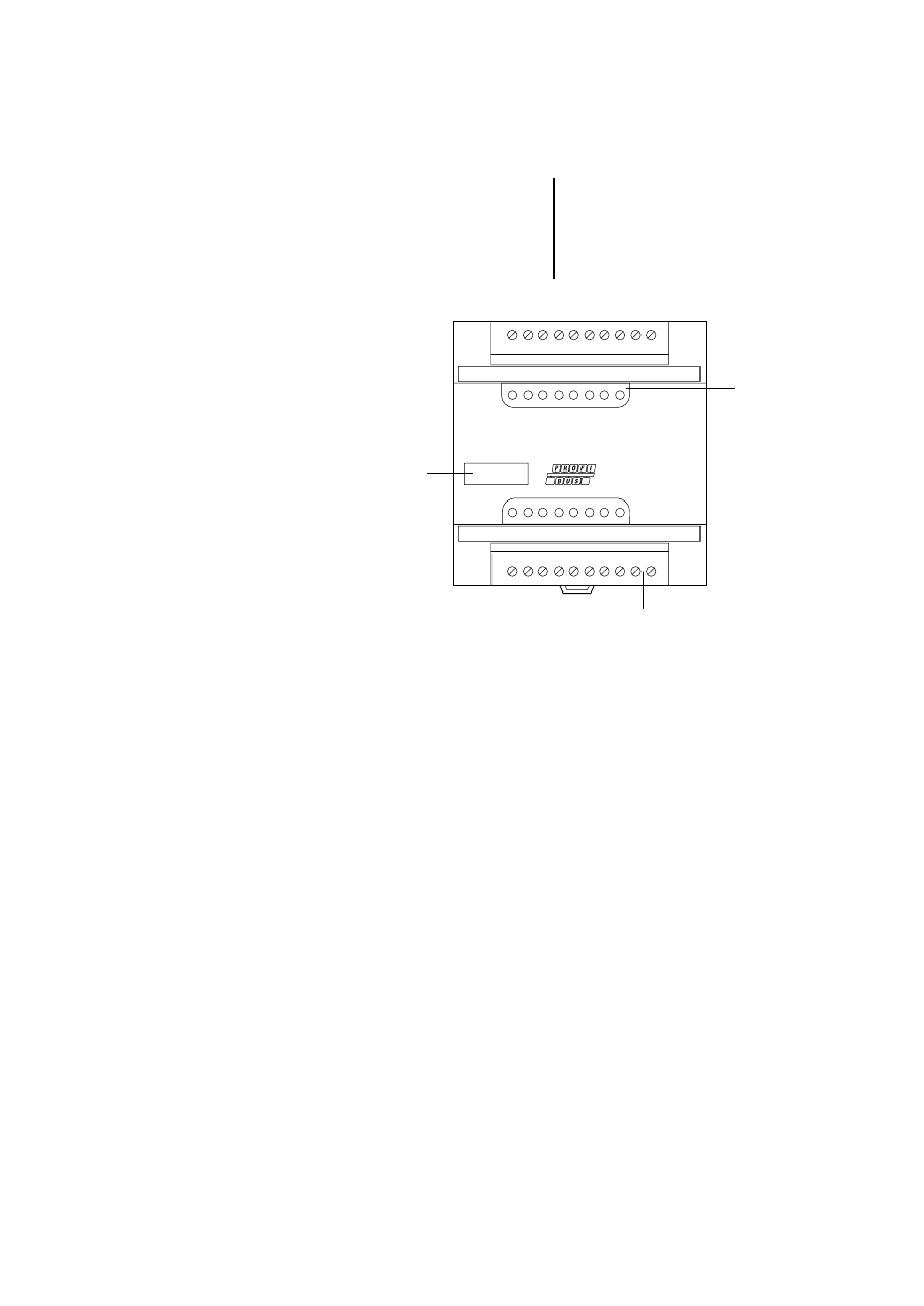
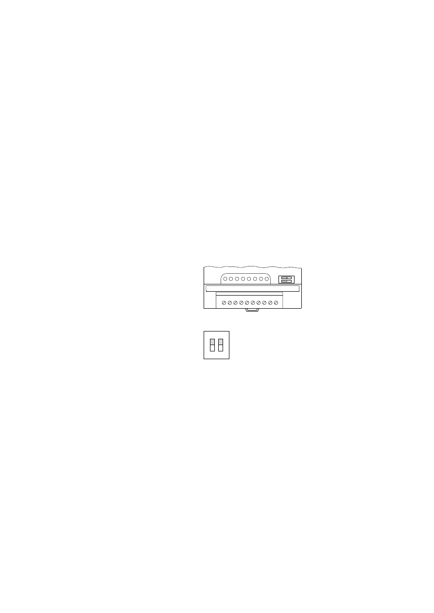
Setup of the
LE 4-504-BS1
Figure 1: LE 4-504-BS1 for PROFIBUS-DP
Device designation HAEG 18 ⫻ 6.5
LEDs
For detailed information about the function of each
LED, see chapter “Testing/Commissioning/
Diagnostics”.
Plug-in screw terminal
For connection of the bus cables (see chapter
“Engineering”).
LE4-504-BS1
B
A
B
A
1=Run
2=Ready
3=Status
4=Error
1 2 3 4
햴
햲
햳
About the local expansion
modules
8
09/99 AWB 2700-1368 GB
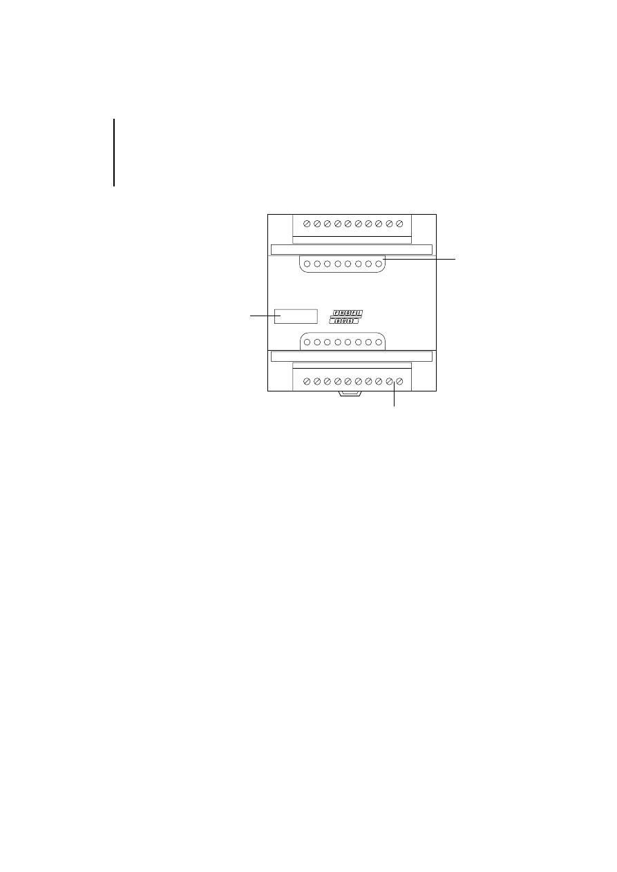
Setup of LE 4-504-BT1
Figure 2: Setup of the LE 4-504-BT1
Device designation HAEG 18 ⫻ 6.5
LEDs
For detailed information about the function of each
LED, see chapter “Testing/Commissioning/
Diagnostics”.
Plug-in screw terminal
For connection of the bus cables (see chapter
“Engineering”).
LE4-504-BT1
B
A
B
A
1=Bus
2=Diag
3=Config Error
1 2 3
햴
햲
햳

9
09/99 AWB 2700-1368 GB
2
Engineering
Electromagnetic
compatibility (EMC)
The following engineering measures must be
observed in order to meet the requirements of the
EMC regulations and comply with the following
European EMC standards:
EN 50 081-2 (Emission)
EN 50 082-2 (Immunity)
Bus and analog lines
Only screened cables must be used for bus and
analog lines (see Page 11).
Other engineering instructions are given in the
manual “EMC Guidelines for Automation
Systems”, AWB 27-1287-GB and the EMC
manual “Electromagnetic Compatibility of
Machines”, TB 02-022 GB.
Attention!
Electromagnetic interference
Interference and line-conducted interference
according to ENV 50 140 and ENV 50 141 can
corrupt measurement readings by up to 20 %.
A faulty connection of the module may produce
interference in other components.
Engineering
10
09/99 AWB 2700-1368 GB
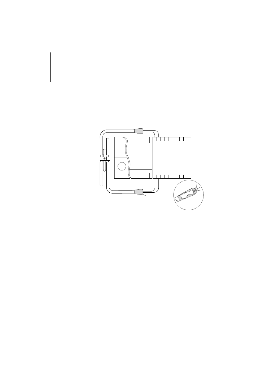
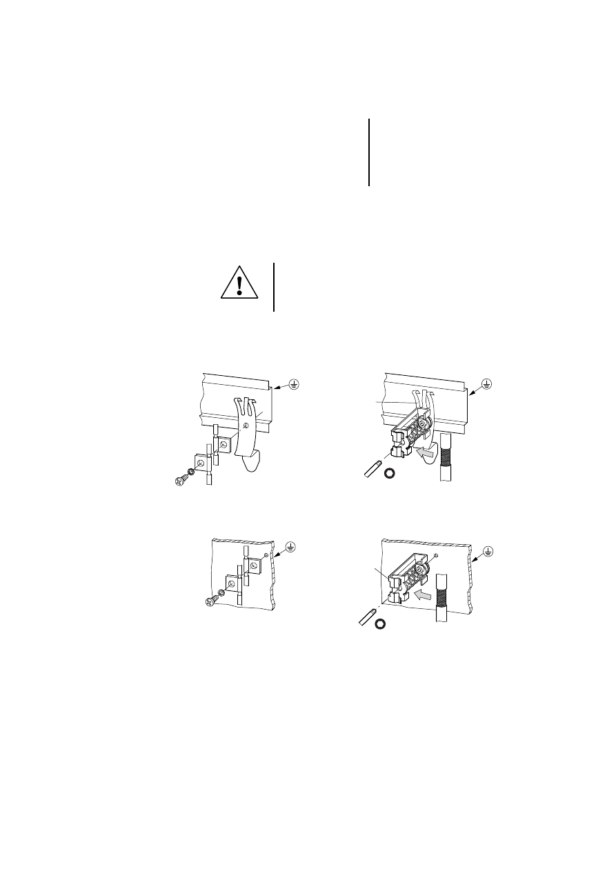
Terminating the bus and analog lines
왘 Pull back the screen at the ends of the bus and
analog input cables.
왘 Isolate the screen with suitable material such as
heat-shrink tubing.
*
Schematic connection
Installation with top-hat rail on mounting plate
Mounting on mounting plate
Grounding the bus and analog lines
왘 Strip the cable sheathing near the contact clip.
왘 Place a contact clip around the insulated section
of the bus and analog lines or press the stripped
section into the snap-on mounting of the terminal
clip.
PS 4/EM 4
LE 4
*
*
Bus and analog lines
11
09/99 AWB 2700-1368 GB
왘 Make a low-impedance connection between the
contact clip or terminal clip and the top-hat rail or
mounting plate.
왘 Fit the top-hat rail to the mounting plate.
왘 Ground the top-hat rail, ensuring a large contact
area.
Attention!
Ensure that all connections are corrosion proof
and that the paint is removed from the
connection point of mounting plates.
M4
ZB 4-102-KS1
FM 4/TS 35
(Weidmüller)
ZB 4-102-KS1
KLBü 3-8 SC
(Weidmüller)

Engineering
12
09/99 AWB 2700-1368 GB
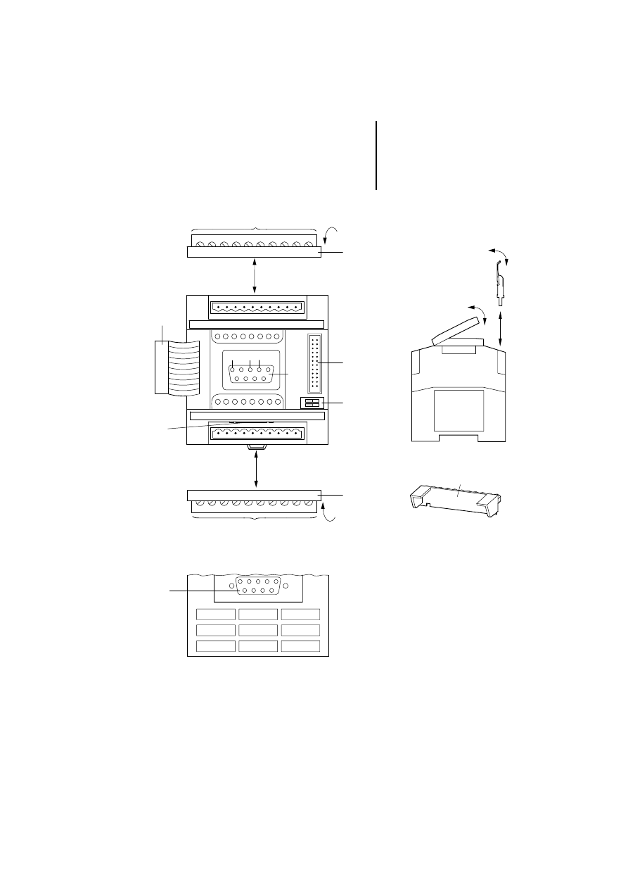
Connections
Legend for Figure 3:
Female connector for connection to the PS 4
Connection cross-sections:
flexible with ferrule 0.22 to 1.5 mm
2
(AWG 23 to AWG 16) solid 0.22 to 2.5 mm
2
(AWG 23 to
AWG 13)
Plug-in screw terminal
A (green)
= RxD/TxD-N receive/transmit data N
B (red)
= RxD/TxD-P receive/transmit data P
Plug connector for connecting further LEs
Switch for bus terminating resistors S1 and S2
PROFIBUS-DP interface; alternative connection for bus
lines via 9-pin Sub-D socket with connector
ZB-9 4-209-DS3, carry out the following steps:
CFG interface (for LE 4-504-BS1 only);
connection for PC with CFG-DP configuration software
via PS 416-ZBK-210 cable
Terminal strip cover, for use with alternative connection
method
Connections
13
09/99 AWB 2700-1368 GB
Figure 3: Connection overview
햲
햳
1 2 3 4
햳
햴
5
4
3
2
1
9
8
7
6
DGND TxD RxD
햸
햷
햵
햶
햴
A B
A B
OFF
12
Engineering
14
09/99 AWB 2700-1368 GB
Connecting to the PS 4
The network LEs can be used only in connection with
the expandable PS 4 series compact PLCs.
Table 1: Using the PROFIBUS-DP module
Figure 4: Connecting a locally expandable PS 4
Due to the current consumption of the
PROFIBUS-DP LEs, there may be a limit to the
expandability with LEs to prevent overloading the
PS 4 compact PLC’s power supply. The
Sucosoft S 40 topology configurator
automatically prevents inadmissible
configurations.
LE 4-504-BS1
(master)
LE 4-504-BT1 (slave)
PS 4-201-MM1
–
X
PS 4-271-MM1
–
X
PS 4-341-MM1
X (1 module)
X
The PROFIBUS-DP master LE 4-504-BS1 can be
used only in conjunction with a PS 4-341-MM1. It
must be placed in the first position, immediately
adjacent to the PLC.

Connections
15
09/99 AWB 2700-1368 GB
Connection to the PROFIBUS-DP
The network LEs are equipped with an isolated
RS 485 interface for connection to PROFIBUS-DP.
The connections are made via the lower plug-in
screw terminal – labelled A and B – or using the 9-pin
Sub-D socket immediately behind the screw
terminal.
왘 Connect PROFIBUS-DP cable ZB 4-900-KB1 by
attaching the green wire to screw terminal A and
the red wire to screw terminal B.
왘 Fit a jumper between the two connection points
of terminal A and between those of terminal B, so
that the screw terminals can be removed without
interrupting communications in the bus line.
왘 Establish the connection between screen and
top-hat rail using mounting kit ZB 4-102-KS1 and
snap-on mounting BT 432. These must be
ordered separately.
Use special PROFIBUS-DP plug ZB 4-209-DS3,
which contains the circuitry required for
interference-free operation up to transfer speeds
of 12 Mbit/s. Connector ZB 4-209-DS3 must be
ordered separately.
Engineering
16
09/99 AWB 2700-1368 GB
If the PROFIBUS-DP line is to be connected to the
Sub-D socket with connector ZB 4-209-DS3, carry
out the following steps:
왘 Release the lower plug-in screw terminal and
remove it.
왘 Cover the exposed terminal strip with the
supplied cover.
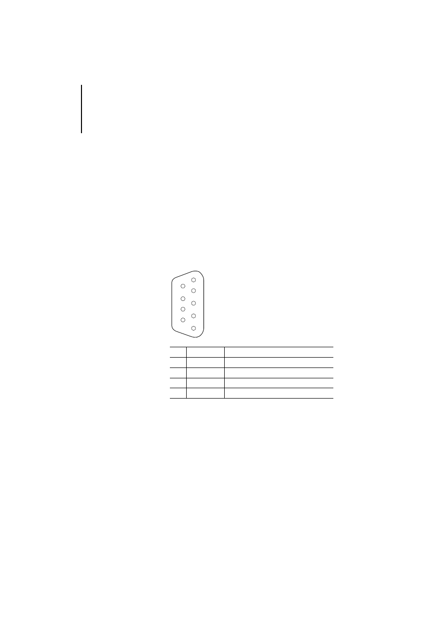
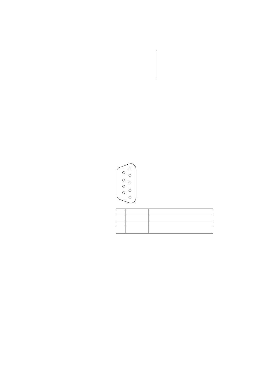
Connection assignment
The PROFIBUS-DP interface is a 9-pin Sub-D female
connector. It has the following pin assignment.
Pin
Designation
Meaning
3
RxD/TxD-P
Transmit/receive data line, positive
5
DGND
Data ground
6
VP
Supply voltage +5 V
8
RxD/TxD-N
Transmit/receive data line, negative
6
7
8
9
2
3
4
5
1
Connections
17
09/99 AWB 2700-1368 GB
Connecting to the CFG interface
The network LE is connected to a PC with the CFG-
DP configuration software via an RS-232C interface
(COM). A female Sub-D connector is provided for this
purpose on the front of the module. Programming
cable PS 416-ZBX-210 can be used to make the
connection. If no cable is connected, the front cover
must be fitted to the connector during operation.
Connection assignment
The CFG interface is a 9-pin Sub-D female
connector. It has the following pin assignment.
Pin
Designation
Meaning
2
RxD
Receive data
3
TxD
Transmit data
5
DGND
Data ground
6
7
8
9
2
3
4
5
1

Engineering
18
09/99 AWB 2700-1368 GB
Connecting a PC
To configure the module with the CFG-DP
configuration software, connect the PC via the pre-
assembled PS 416-ZBX-210 cable to the module.
The cable has a length of two metres. If this is not
long enough, you can optionally use data connectors
PS 416-ZBS-411 and PS 416-ZBS-410 to connect
your own cable between the module and the PC’s
COM interface. The cable must be no longer than
15 m.
Long cables can cause EMC problems in noisy
environments.
19
09/99 AWB 2700-1368 GB
3
Mounting
Modules LE 4-504-BS1 and LE 4-504-BT1 can be
mounted on a top-hat rail or with fixing brackets.
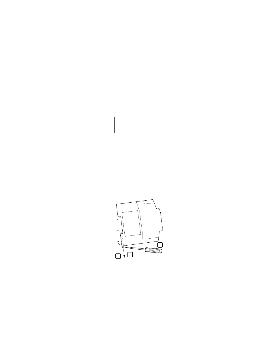
Mounting on a top-hat
rail
왘 Hook the back of the device onto the top edge of
the top-hat rail.
왘 Use a screwdriver to slide the spring-loaded
clip
out of the device
.
왘 Push the device against the top-hat rail
.
왘 Remove the screwdriver. The spring-loaded clip
should snap back into position and hold the
device securely.
왘 Check that the device is attached securely.
Figure 5: Mounting on top-hat rail
Before you connect the network LE to the PS 4,
the device must be clipped onto the top-hat rail
or fitted to the mounting plate.
1
2
3
Mounting
20
09/99 AWB 2700-1368 GB
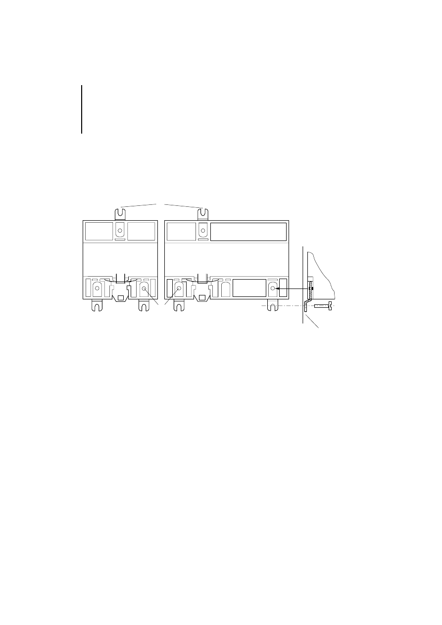
Mounting on fixing
brackets
왘 Push the fixing brackets in until they engage
.
왘 Check that the PLC is seated correctly. The
locating pin must be located in the bore
.
왘 Attach the fixing brackets on the mounting
plate
with M 4 screws.
Figure 6: Mounting on fixing brackets
햲
햴
LE 4 -...
EM 4 -... / PS 4-...
햳
햳
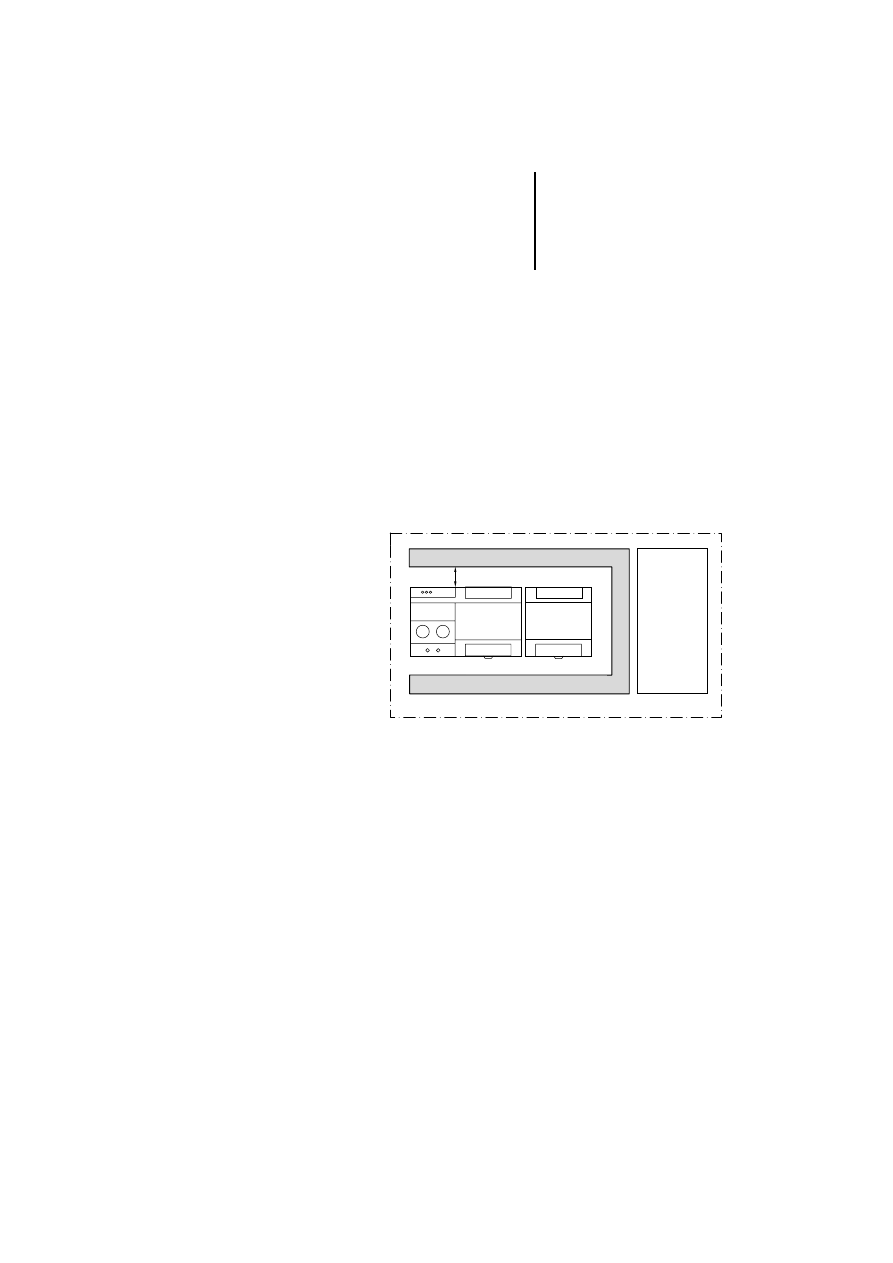
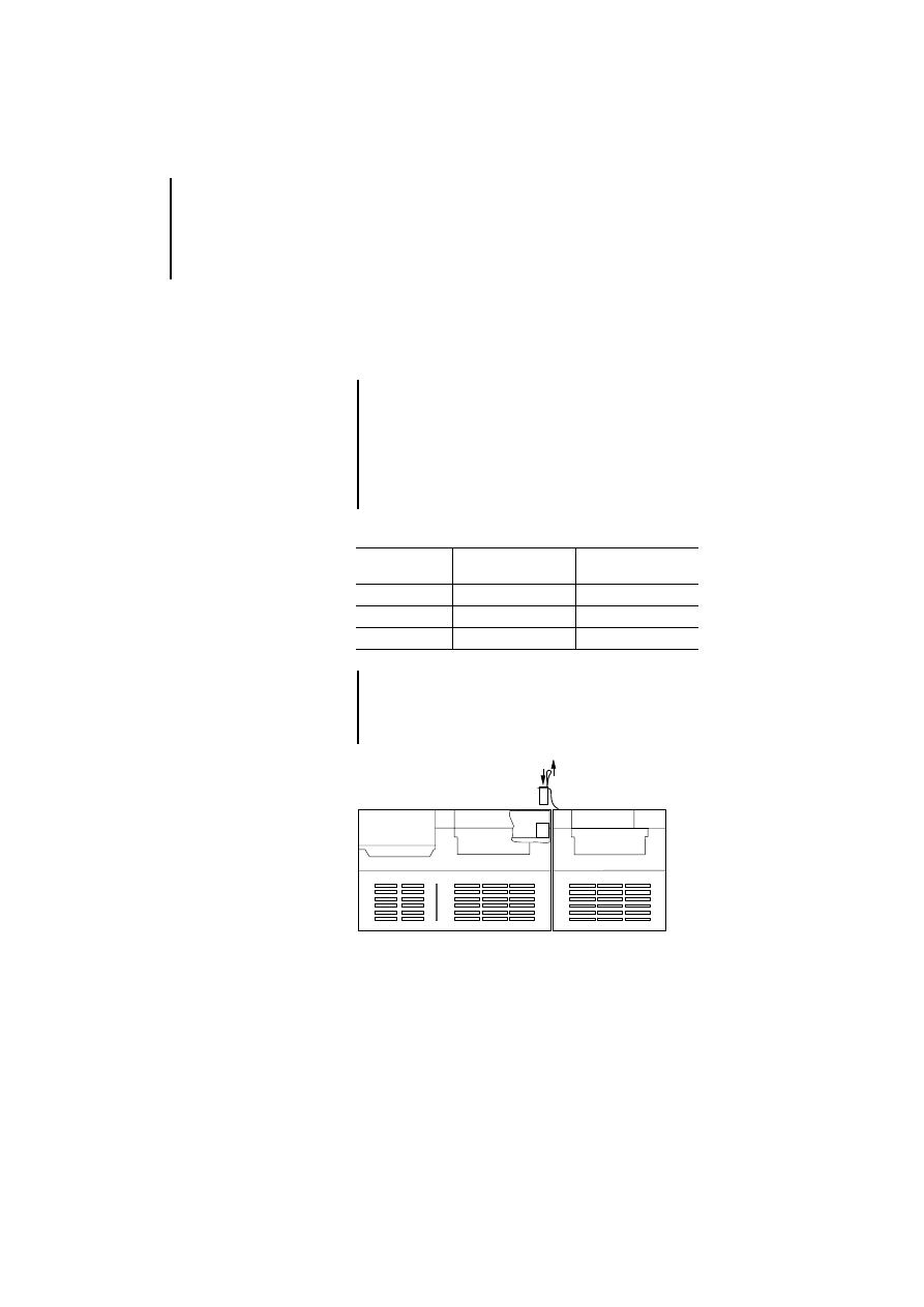
Installing in control cabinet
21
09/99 AWB 2700-1368 GB
Installing in control
cabinet
Observe the following requirements:
왘 Install the locally expandable PS 4 with your local
expansion modules horizontally in the control
cabinet.
Proceed as follows to prevent electromagnetic
interference from impairing the function of the
control electronics:
왘 Ensure a spacing between the cable duct
and
the local expansion modules of at least 50 mm
(2 inches).
왘 Keep the control
and power sections
apart.
Figure 7: Horizontal arrangement of modules in the control
cabinet
햲
햴
50
햳

22
09/99 AWB 2700-1368 GB
23
09/99 AWB 2700-1368 GB
4
Hardware Configuration
Setting the bus
terminating resistors
The bus terminating resistor prevents interference
caused by reflection at the bus cable ends.
They must be switched on if the module is the first or
last physical station on a PROFIBUS-DP line.
This can be done in one of two ways:
You can use the network LE’s bus terminating
resistors.
왘 Open the front panel of the network LE.
왘 Place DIP switch S1 to its ON position.
OFF
12
S1
2
1
OFF

Hardware Configuration
24
09/99 AWB 2700-1368 GB
If you are connecting the PROFIBUS-DP line via the
9-pin Sub-D connector and connector
ZB 4-209-DS3 with integrated bus terminating
resistor:
왘 Set DIP switch S1 on the network LEs to OFF.
왘 Activate the bus terminating resistor on the
connector.

25
09/99 AWB 2700-1368 GB
5
Software Configuration
Network LEs are always used in conjunction with a
locally expandable PS 4 compact PLC. As a rule, the
network LE must be integrated into the PS 4
configuration.
CFG files
For configuring PROFIBUS-DP LEs LE 4-504-BS1
and LE 4-504-BT1, you will need the configuration
and library files included in version 4.0 or higher of
the Sucosoft S 40 software.
You can select the PROFIBUS-DP LEs from the Local
Expansion list in the Sucosoft S 40 Topology
Configurator.
GSD files
To incorporate the network LEs into PROFIBUS-DP
communications, you will need the module master
data in the form of the GSD files. These files, which
are required for adjusting the communication
parameters, can be incorporated into the
configuration tools of any PROFIBUS-DP master,
e.g. the Sucosoft S 40 CFG-DP software.
The GSD files are included in configurator CFG-DP.
They are also available for download from the
Moeller website at www.moeller.net (under
“Automation User Support”) or from the PROFIBUS
User Organization (PNO) at www.profibus.com.
Software Configuration
26
09/99 AWB 2700-1368 GB
Configuring and setting
parameters of
LE 4-504-BS1
CFG Configurator
With the CFG-DP configuration software, you can
configure and define the parameters for the master
LE – LE 4-504-BS1 – which manages the
PROFIBUS-DP line. The CFG-DP configuration
software and its user manual,
AWB-EM 2700-1336 GB, are included in the
package content.
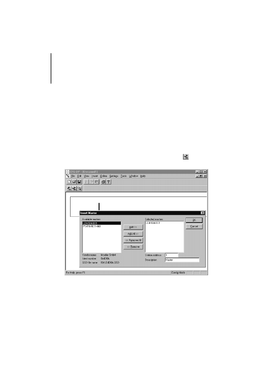
왘 Start the CFG-DP configurator.
왘 Select ‹File ➞ New›.
왘 Select ‹Insert ➞ Master or click on
and then
the left side of the schematic network line.
Configuring and setting
parameters of
LE 4-504-BS1
27
09/99 AWB 2700-1368 GB
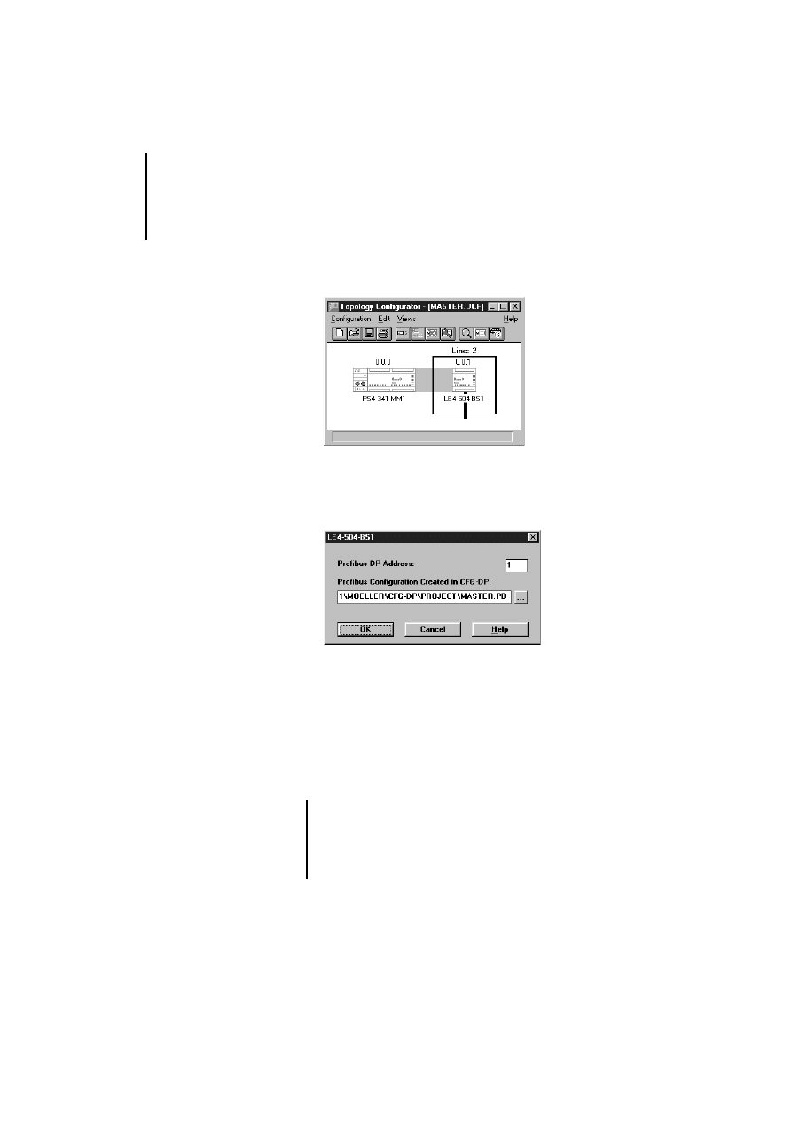
왘 In the left list, double-click on “LE 4-504-BS1”
and, under “Station address”, assign a
PROFIBUS-DP address. Optionally, you can also
enter a descriptive name in the “Description”
field.
For each station (master, slave), the PROFIBUS-DP
address can be in the range 1 to 125.
왘 Confirm with “OK”.
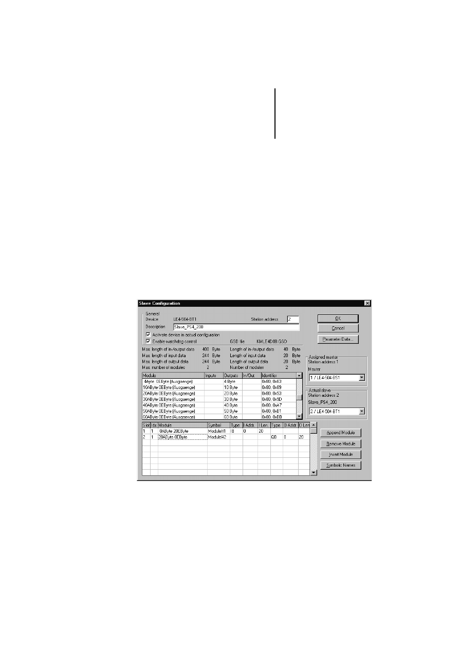
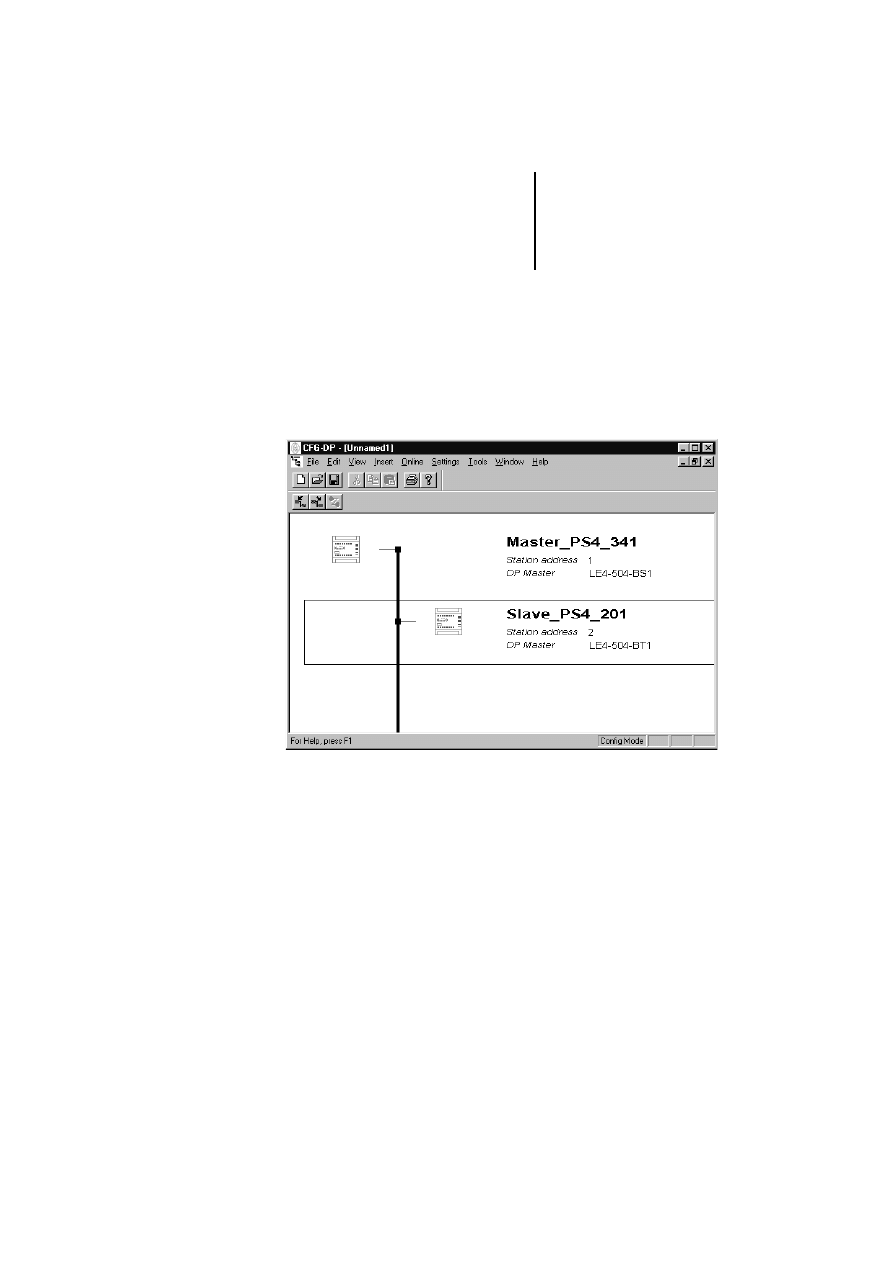
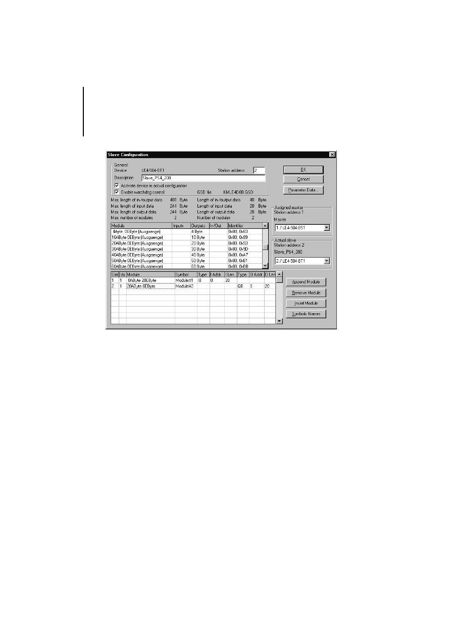
왘 One by one, select the slave stations in the
PROFIBUS-DP line. Where they are not already
predefined, specify their station address and the
send and receive data.
The LE 4-504-BT1 with “Station address 2” in the
example has 20 send and 20 receive data bytes.

Software Configuration
28
09/99 AWB 2700-1368 GB
왘 Having set the parameters for and configured all
slave stations, save the PROFIBUS-DP
configuration.
왘 Using the PS 416-ZBX-210 programming cable,
connect your PC’s serial port to the CFG interface
of the LE 4-504-BS1. The interface is located
behind the front cover.
왘 Select ‹Online ➞ Download› to transfer the
PROFIBUS-DP configuration to the master
module.
For a detailed description of the download
procedure, refer to the description of the CFG-DP
configurator, which is included as an Acrobat (PDF)
file on the Sucosoft S 40 CD-ROM and in the online
help for the configurator.
Attention!
The send and receive data (input and output
data) can be stored in various modules. An
example of this is the locally expandable
EM 4-204-DX1 with its digital inputs. Here, the
data can be physically located on different
modules. In the example for the LE 4-504-BT1,
these data storage areas are physically located
on the same module, even though their virtual
(software-defined) location is split over two
modules. This must always be taken into account
with the five-digit address notation when
addressing the slave stations within Moeller PLC
programs. For further information about
addressing in the PLC program, see chapters
“Operation” and “Testing/Commissioning/
Diagnostics”.
Configuring and setting
parameters of
LE 4-504-BS1
29
09/99 AWB 2700-1368 GB
Topology Configurator
The LE 4-504-BS1 master module can be configured
with the Sucosoft S 40 Topology Configurator.
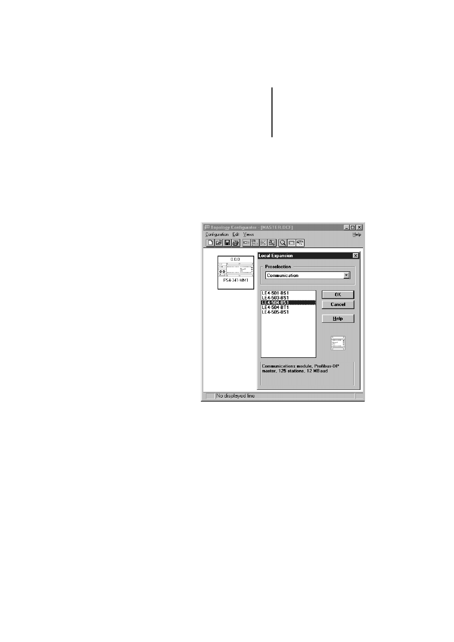
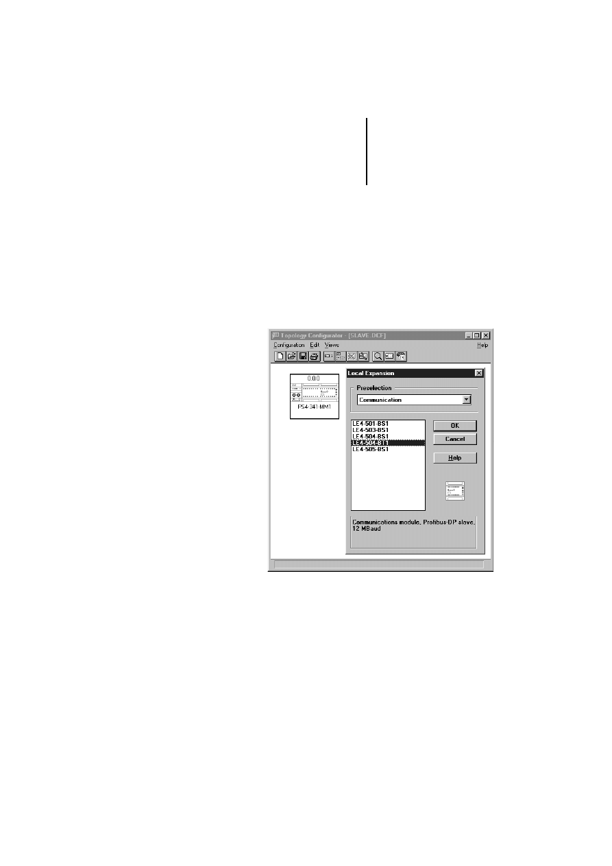
왘 Create a new topology configuration with a
PS 4-341-MM1.
왘 Select ‹Edit ➞ Local Expansion›.
Software Configuration
30
09/99 AWB 2700-1368 GB
왘 Highlight the master LE in the list and confirm
with “OK”.
왘 Select ‹Edit ➞ Set Parameters› and, in the dialog
that now opens, assign the PROFIBUS-DP
address for the LE 4-504-BS1.
왘 In the field “Profibus Configuration Created in
CFG-DP”, enter the path and name of the file
created with the CFG-DP PROFIBUS-DP
configurator or select the file with the button next
to the field.
The reference to the PROFIBUS-DP configuration file
is required for consistency checks by the Sucosoft
user program.
If a new or modified PROFIBUS-DP configuration
is loaded onto the LE 4-504-BS1 with the
CFG-DP, the user program of the PS 4-341-MM1
must be re-compiled with “Generate All” and
resent to the PS 4-341-MM1.
Configuring and setting
LE 4-504-BT1 parameters
31
09/99 AWB 2700-1368 GB
왘 Complete and save the local and remote
PS 4-341-MM1 configurations.
Configuring and setting
LE 4-504-BT1
parameters
The LE 4-504-BT1 slave module can be configured
with the Sucosoft S 40 Topology Configurator.
왘 Create a new topology configuration with a locally
expandable PS 4-MM1 PLC.
왘 Select ‹Edit ➞ Local Expansion›.
왘 Highlight the slave LE in the list and confirm with
“OK”.
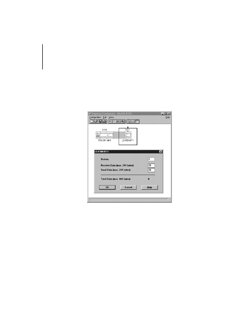
왘 Select ‹Edit ➞ Set Parameters›
왘 Enter the slave address, to which the
LE 4-504-BT1 is to be assigned on the
PROFIBUS-DP line.
Software Configuration
32
09/99 AWB 2700-1368 GB
왘 Using the list boxes, select the number of send
and receive data bytes for communication. The
data bytes specified here must correspond with
the data bytes configured for the respective line
master for data exchange with the LE 4-504-BT1
(see example with LE 4-504-BS1 as master,
below).
왘 Complete and save the local and remote PLC
configurations.
왘 Start the CFG-DP configurator.
왘 With ‹File ➞ Open›, open the configuration into
which you want to insert the LE 4-504-BT1 as
slave.
왘 Select ‹Insert ➞ Slave› and click the right section
of the schematic network line.
Configuring and setting
LE 4-504-BT1 parameters
33
09/99 AWB 2700-1368 GB
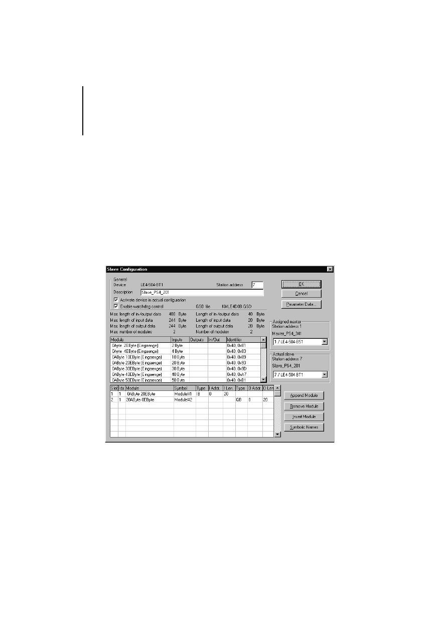
왘 In the left list, double-click the entry
“LE 4-504-BT1” and assign a PROFIBUS-DP
address under “Station address” and, optionally,
a representative name under “Description”. For
each station (master, slave), the PROFIBUS-DP
address can be in the range 1 to 125.
왘 Confirm with “OK”.
왘 Now specify the send and receive data lengths
for the LE 4-504-BT1.
Software Configuration
34
09/99 AWB 2700-1368 GB
왘 Having set the parameters for and configured all
slave stations, save the PROFIBUS-DP
configuration.

35
09/99 AWB 2700-1368 GB
6
Operation
Addressing the
modules
PROFIBUS-DP modules
Moeller’s 5-digit notation is used for reading and
writing in the PROFIBUS-DP network line. A
mirroring procedure is used to access the data. At
the beginning of each program cycle, the input
values are read from the dual-port RAM of
LE 4-504-BS1 and LE 4-504-BT1, and at the end of
the program cycle, the output values are written to
the dual-port RAM of LE 4-504-BS1 and
LE 4-504-BT1.
The I/O data can be accessed in bit, byte, word, or
double word format.
The data is assigned to the user program variables
when the variables are declared in the user program
by Sucosoft S 40.
The address notation corresponds with the notation
for Suconet K:
<Line No.> . <Station No.> . <Module No.> . <Byte/Word/Double Word> . <Bit>
Operand:
I, Q (master); RD, SD (slave)
Data width: X, B, W, D
For addressing slave module LE 4-504-BT1, the first
two places of the address –
<Line No.>
and
<Station
No.>
are always “0”. The third defines the slot in
which the module is located (1 or 2).
Operation
36
09/99 AWB 2700-1368 GB
The master declares the input and output data in
packets as separate modules, even if the network
station consists of only one physical module. The
input and output data is addressed through different
module numbers.
A user program may therefore have different
numbers for input and output data in the third place
of the five-digit address.
Example:
Slave LE 4-504-BT1 is connected to line 1 and has
20 input and 20 output bytes.

Addressing the modules
37
09/99 AWB 2700-1368 GB
The output data from the slave is shown in the lower
list box, labelled “Module#2”, and will be read by
master LE 4-504-BS1 via address operators
%IB1.7.1.0 to %IB1.7.1.19.
The slave input data, labelled “Module#1”, is
supplied by master LE 4-504-BS1 with address
operators %QB1.7.0.0 to %QB1.7.0.19.
The address notation is documented in detail in
manual AWB 2700-1306 GB “Sucosoft S 40:
Language Elements for PS 4-150/-200/-300 and
PS 416”, chapter 2, section “Directly represented
variables”.
PROFIBUS-DP stations
Master LE 4-504-BS1 manages the PROFIBUS-DP
line. The line number is assigned automatically in the
Sucosoft S 40 Topology Configurator.
In the Sucosoft S 40 Topology Configurator, enter
the slave’s station number, which is the same as the
“Station address” in the CFG-DP configurator.
The address notation requires the listed module
number – “Module#x” – to be reduced by “1”
each time in the PROFIBUS-DP configurator.

Operation
38
09/99 AWB 2700-1368 GB
Moeller slave devices consisting of several modules
(e.g. an EM 4-204-DX1 with local expansion
modules), are addressed in the order in which they
are connected. The EM 4 would then have the
module number 0 and the connected LE 4s module
numbers 1 to 6 in ascending order.
Other makes of PROFIBUS-DP station are
addressed in accordance with the description in the
associated device master data (*.GSD) files. Consult
the device’s documentation for address details.
Example for LE 4-504-BS1:
VAR
Analog_Input AT %IW2.3.1.0 : INT;
(* Analog input word 0 of 1st LE of
3rd station in 2nd line *)
Limit_Value : INT := 800 ;
END_VAR
LD
Analog_Input
GT
Limit_Value
JMPC
Alarm
.
.
.
Alarm:
To address the input and output values of the
PROFIBUS-DP stations, master LE 4-504-BS1
must use address ID %I or %Q, , with a
corresponding data width definition (X, B, W or
D). There are, for example, no special IDs for
analog values (%IAW, %QAW), They are
addressed via normal input or output addresses.

Function of LE 4-504-BS1
39
09/99 AWB 2700-1368 GB
Example for LE 4-504-BT1:
VAR
Set_Speed AT %SDW0.0.4.0:INT;
(*Sends an integer value
to the master's receive data field*)
Default:INT:=800;
END_VAR
LD
Default
ST
Set_Speed
.
.
.
Function of
LE 4-504-BS1
After the PLC is powered up, LE 4-BS1 performs a
self-test. Any errors during the self-test are indicated
by the LEDs on the front-panel (see Page 44).

40
09/99 AWB 2700-1368 GB

41
09/99 AWB 2700-1368 GB
7
Testing/Commissioning/Diagnostics
Commissioning the
LE 4-504-BS1
Commissioning the LE 4-504-BS1 requires the
following steps:
왘 With the CFG-DP configurator, transmit the
created PROFIBUS-DP line configuration to the
LE 4-504-BS1.
왘 In the Sucosoft S 40 Topology Configurator,
create the configuration for the PS 4-341-MM1 to
which the LE 4-504-BS1 is connected. When the
program code is generated, this configuration is
linked with the PLC user program and then sent
to the PS 4-341-MM1 with Sucosoft S 40.
The exact procedure is described in the
electronic documentation of the CFG-DP
configurator, which is included as a PDF file on
the Sucosoft S 40 CD-ROM.
The configuration of LE 4-504-BS1 is only
accepted by the PS 4-341-MM1 operating
system during the initial cold start of an
application.
For fault correction or for a version update it may
be necessary to load new firmware onto the
LE 4-504-BS1. New firmware versions are
announced in the Sucosoft S 40 Readme file, the
mailbox support pages and on the Moeller
website. The firmware download procedure is
described in the electronic documentation for the
CFG-DP configurator, which is included on the
Sucosoft S 40 CD-ROM as a PDF file.

Testing/Commissioning/
Diagnostics
42
09/99 AWB 2700-1368 GB
If the configuration of the PROFIBUS-DP network
line is modified or if the LE 4-504-BS1 is replaced,
then the configuration must be reloaded to the
PS 4-341-MM1.
During operation, diagnostic data from the
LE 4-504-BS1 and the network slave can be
evaluated either using diagnostic bytes or function
block “PdpStationDiag” in the PS 4-341-MM1 user
program (see function block “PdpStationDiag on
Page 56).
PROFIBUS-DP communication
The start of communications is dependent on the
operational status of the PS 4-341-MM1.
If the LE 4-504-BS1 is correctly entered in the
PS 4-341-MM1 topology configuration, data
communication on the PROFIBUS-DP line starts
when the status of the PS 4-341-MM1 changes from
“ready” to “run”.
When an error occurs and the status of the
PS 4-341-MM1 changes from “run” to “ready” or
“not ready”, data exchange in the PROFIBUS-DP line
stops, and the “run” LED on the LE 4-504-BS1
flashes at regular intervals.

Commissioning the
LE 4-504-BT1
43
09/99 AWB 2700-1368 GB
Commissioning the
LE 4-504-BT1
Commissioning the LE 4-504-BT1 consists of the
following steps:
왘 In the Sucosoft S 40 Topology Configurator,
create the configuration for the slave CPU PS 4 to
which the LE 4-504-BT1 is connected.
When the program code is generated, this
configuration is linked with the PLC user program. It
must then be sent to the slave CPU PS 4 with
Sucosoft S 40.

Testing/Commissioning/
Diagnostics
44
09/99 AWB 2700-1368 GB
Status indication in the
operating phase
The status of the LE 4-504-BS1 and PROFIBUS-DP
communications is indicated by four LEDs. The
LE 4-504-BT1 has three LEDs for this purpose. They
are located on the module’s front panel.
During error-free data exchange with all
configured stations, all three LEDs of the
LE 4-504-BS1 are lit. They are:
“run”, “ready” and “status”.
LED
Colour
Status
Meaning
LE 4-504-BS1
run
green
on
Communication with at least one station in progress
cyclic flashing
Ready for communication
acyclic flashing
Parameterization error
off
Communication interrupted
ready
yellow
on
LE 4-504-BS1 ready
cyclic flashing
Firmware must be transmitted or is being transmitted
(1 Hz and 2 Hz)
acyclic flashing
Hardware or firmware fault
off
Hardware fault
status
yellow
on
LE 4-504-BS1 has the token and is currently active line
master
error
red
on
Error during communication transfer
LE 4-504-BT1
bus
yellow
on
User data exchange with the PROFIBUS-DP master
flashing
No user data exchange. If the “config-error” LED also
flashes, the actual and set configuration do not correspond.
off
Startup phase
diag
red
on
A hardware fault has occurred in the device. The “config-
error” LED is also lit.
off
Hardware OK
config-error red
on
Hardware fault in device. The “diag” LED is also lit.
flashing
Actual configuration deviates from set configuration. The
“bus” LED is also lit.
off
Configuration OK
Overview of diagnostic
bytes
45
09/99 AWB 2700-1368 GB
Overview of diagnostic
bytes
Error messages of master CPU:
Data synchronization between PS 4-341-MM1
and LE 4-504-BS1
Diagnostic byte from master LE 4-504-BS1:
Information about master LE 4-504-BS1; group
information from slaves
Diagnostic byte from slave LE 4-504-BT1:
Byte0: information about status of slave LE 4-504-BT1;
read by the slave CPU
Byte1: communication status of slave LE 4-504-BT1;
read by the slave CPU
Extended byte1: information about slave CPU; master
CPU reads operating status of slave CPU
Extended byte2: service information about slave CPU
(e.g. state of backup battery)
General byte: indicator for extended diagnostic data
from slave; read by the master CPU
Function block “PdpStationDiag”:
Extended diagnostic message from slave; called by the
master CPU
Master PS 4-341-MM1
Slave PS 4-201-MM1
LE 4-504-BT1
LE 4-504-BS1
Slave: PS 4-271-MM1
PS 4-341-MM1
LE 4-504-BT1
c, d
c, d
a, b, e
f, g, h

Testing/Commissioning/
Diagnostics
46
09/99 AWB 2700-1368 GB
Diagnostic bytes indicate errors that have occurred
during testing, commissioning or operation. Their
physical location is
in master CPU PS 4-341-MM1 (
,
)
in master LE 4-504-BS1 (
)
in slave LE 4-504-BT1 (
,
,
,
,
)
Diagnostic bytes are called, however, in the PLC’s
user program. The following bytes are used:
,
,
,
,
,
in the user program of master
CPU PS 4-341-MM1
,
in the user program of slave CPU
PS 4-201-MM1/-271-MM1/-341-MM1
CPU error messages
Messages from operating system
PS 4-341-MM1
During operation of the PS 4-341-MM1 with the
LE 4-504-BT1 module, errors may arise during
transfer or cold start of the user program.
If, during the cold start of a user program, an I/O
error message appears, check the user
program’s I/O declarations in PROFIBUS-DP
operation against the S 40 configuration and
against the PROFIBUS-DP configuration.

CPU error messages
47
09/99 AWB 2700-1368 GB
The following error codes are possible:
82C0
Error when reading the PROFIBUS-DP
configuration (message during cold start)
82C2
LE 4-504-BT1 has no PROFIBUS-DP
configuration (message after transfer)
80FE
Error during parameter configuration of
LE 4-504-BT1 (message after transfer or
during cold start; internal error)
82C3
Not enough free memory available for
PROFIBUS-DP configuration (message
during cold start)
82C4
No station with the specified address exists
in the PROFIBUS-DP configuration
(message after cold start)
82C5
More than 24 modules have been
configured for one station (message after
cold start)
82C6
The operating system of the PS 4-341-MM1
does not know the configuration of the
PROFIBUS-DP line, because
the module is not inserted;
the assignment of line numbers to slot
numbers in the topology configuration is
not correct.

Testing/Commissioning/
Diagnostics
48
09/99 AWB 2700-1368 GB
Diagnostic byte of
master module
LE 4-504-BS1
The LE 4-504-BS1 provides the user program with a
diagnostic byte, which is addressed with the type
“IS” input operator.
Because the LE 4-504-BS1 can only be connected
directly adjacent to the PS 4-341-MM1, the
diagnostic byte is declared as follows:
VAR
Status_BS1 AT %ISB0.0.1.0 : BYTE ;
END_VAR
The meaning of the bits of the diagnostic byte is as
follows:
During error-free operation, all bits have the value
“0”.
Bit 0:
no/unexpected type; is set when the slot
contains no LE or an LE other than
LE 4-504-BS1.
Bit 1:
Reserved
Bit 2:
Reserved
Bit 3:
Group information; is set when a configured
station does not report on the bus. (“error”
LED of LE 4-504-BS1 is lit)
Bit 4:
timeout; is set when LE 4-504-BS1 does not
respond.
Bit 5:
is set when the PLC doe not exchange data
with any station in operating status “run”.
Bit 6:
is set, when the LE 4-504-BS1 does not have
a valid configuration.
Bit 7:
is set, when the LE 4-504-BS1 has not
performed a self-test.

Slave module diagnostic
bytes
49
09/99 AWB 2700-1368 GB
Evaluation of the diagnostic byte in the user program
must consist of either:
evaluating the individual bits using the special
Moeller point notation
LD Status_BS1 (* Station on line is not reporting*)
or
checking the whole diagnostic byte for errors
LD
Status_BS1
NE
0
JMPC
Error
Slave module
diagnostic bytes
LE 4-504-BT1
The LE 4-504-BT1 provides the user program with
two diagnostic bytes, which are addressed with the
type “IS” input operator.
If LE 4-504-BT1 is on slot 2 next to the expandable
PS 4, the diagnostic bytes for the module are
declared as follows:
VAR
Status1_BT1 AT %ISB0.0.2.0 : BYTE ;
Status2_BT1 AT %ISB0.0.2.1 : BYTE ;
END_VAR

Testing/Commissioning/
Diagnostics
50
09/99 AWB 2700-1368 GB
BYTE 0
Bit 0:
The module is either missing, defective or of
an incorrect type (i.e. the connected module
does not correspond with the topology
configuration). The signal is cleared
automatically once the fault is rectified. A
reset in the diagnostic status of the CPU is
not necessary.
Bit 1:
If a hardware fault has occurred, replace the
faulty module. The signal is cleared
automatically once the fault is rectified. A
reset in the diagnostic status of the CPU is
not necessary.
Bit 2:
If the input/output values are invalid, the
module performs an internal parameter
configuration shortly after power is restored
or the program is transferred. During this
time, the values that were read or written are
invalid. Permissible values can be read or
output as soon as the signal is cleared,
which happens automatically once the fault
is rectified.
A reset in the diagnostic status of
the CPU is not necessary.
Bit 3:
In case of a timeout, the communication
partner does not respond. This is either due
to a faulty module or a fault in the
PROFIBUS-DP line. Switch the system off
and on again and observe the notes about
cable routing in the manuals. which happens
automatically once the fault is rectified. A
reset in the diagnostic status of the CPU is
not necessary.

Slave module diagnostic
bytes
51
09/99 AWB 2700-1368 GB
BYTE 1
Bit 2:
A configuration error indicates that the local
configuration does not match the sent
PROFIBUS-DP configuration of the master.
Check the configured send and receive data
lengths in the Sucosoft S 40 topology
configuration and the PROFIBUS-DP
configuration of the master. which happens
automatically once the fault is rectified. A
reset in the diagnostic status of the CPU is
not necessary.
Bit 3:
If “SYNC” is active, the station’s receive data
(the output data for the PROFIBUS-DP
master) has been frozen with a “SYNC”
command from the master. The message
disappears automatically when an
“UNSYNC” command is received.
Bit 4:
If “FREEZE” is active, the module’s send
data (the input data for the PROFIBUS-DP
master) has been frozen with a “FREEZE”
command from the master. The message
disappears automatically when an
“UNFREEZE” command is received.
For a description of the “PdpFreezeSync”
function block, refer to manual AWB 2700-1306
“Language elements for PS 4-150/-200/-300 and
PS 416”.

Testing/Commissioning/
Diagnostics
52
09/99 AWB 2700-1368 GB
Bit 6:
If no PROFIBUS-DP communication is
taking place, the master of the
PROFIBUS-DP line does not exchange user
data with the station. Check:
the master’s power supply
that the master is in the correct operating
mode for communication
for an interrupted connection
that the PROFIBUS-DP address is
correct
that the station has been configured in
the PROFIBUS-DP configurator
that the data length in the PROFIBUS-DP
configurator corresponds with the locally
configured data lengths. If the
configuration data is not the same, bit 2 –
“config-error” – is set.
The signal is cleared automatically once the
fault is rectified.
A reset in the diagnostic
status of the CPU is not necessary.

Slave module diagnostic
bytes
53
09/99 AWB 2700-1368 GB
Module LE 4-504-BT1 provides extended, station-
specific information to the respective PROFIBUS-DP
master in the line. On PROFIBUS-DP masters
PS 416-NET-440 and LE 4-504-BS1 from Moeller,
this extended information is queried with the help of
function block “PdpStationDiag”. For details about
querying extended diagnostic data with other
PROFIBUS-DP masters, refer to the manufacturer’s
documentation.
The extended diagnostic information is stored in two
bytes, whose significance is also detailed in the GSD
file:
First byte of the extended diagnosis
Bit 0:
The PLC is in “Not Ready” state. PLC PS 4
with module LE 4-504-BT1 has a fatal error
or does not have an operating system
(PS 4-341-MM1). Load an operating system
or replace the CPU.
Bit 1:
The PLC is in “Halt” mode. PLC PS 4 has
stopped.
Bit 2:
If the message “Diag” appears, one or more
diagnostic messages are pending on PLC
PS 4. In Sucosoft S 40, call up the diagnostic
messages with “Test & Commissioning” and
check the extended information in the
second byte.

Testing/Commissioning/
Diagnostics
54
09/99 AWB 2700-1368 GB
Second byte of extended diagnosis
(message bits of host CPU)
Slave stations – general
Each slave in the PROFIBUS-DP has a diagnostic
byte that can be addressed with the type “IS” input
operator by the user program of master CPU PS 416
or the network master LE 4-504-BS1. The line
number and station number are determined by the
configuration; the module number is always “0”.
Bit 0:
If the message “DAK” appears, there is an
error in the local configuration. The topology
configuration for the PS 4 to which
LE 4-504-BT1 is connected is not the same
as the actual configuration. If no module is
recognized as being connected, then either
the module has not responded to addressing
or a module that is not connected has been
addressed.
Bit 1:
If the message “DDK” appears, there is an
error in the remote configuration.
The
configuration of one or more network
stations connected to the PS 4, is not
correct, i.e. the entered type designation is
not the same as that of the connected
device.
Bit 2:
The message “DBM” – Battery Monitor –
indicates, that the backup battery of the
PS 4 is exhausted and must be replaced, or
that no buffer battery is installed.

Slave module diagnostic
bytes
55
09/99 AWB 2700-1368 GB
Example:
The diagnostic byte of the tenth station on network
line 2 is assigned by the variable declaration.
VAR
Status_Slave AT %ISB 2.10.0.0 : BYTE ;
END_VAR
Bits 4 and 6 are required for diagnosis. They can be
declared and evaluated as Boolean variables.
VAR
Bit4_Slave10 AT %IS2.10.0.0.4 : BOOL ;
Bit6_Slave10 AT %IS2.10.0.0.6 : BOOL ;
END_VAR
In the former case, only those bits relevant to the
diagnostic byte must be filtered out before evaluation
(in the example these are bits 4 and 6):
LD
2#01010000
AND
Status_Slave
ST
Cleared
The meaning of the two relevant bits is as follows:
Bit 4:
Diagnostic bit.
Extended diagnostic data for the station is
available. This data can be read in the user
program with function block
“PdpStationDiag”. This bit is reset to “0”
after it is evaluated by the function block.
Bit 6:
Communication bit.
This is set when there is a fault in the data
exchange with the station, for example when
the station is not connected or is incorrectly
configured.

Testing/Commissioning/
Diagnostics
56
09/99 AWB 2700-1368 GB
Function block
“PdpStationDiag”
Extended diagnostic messages from slaves
Requesting diagnostic data from
PROFIBUS-DP station
Function block prototype
Meaning of operands
PdpStationDiag
Diagnostics
Diagnostics
ARRAY[1..100] OF BYTE
BOOL
Strobe
Active
BOOL
USINT
MasterSlot
State1
BYTE
USINT
StationAddress
State2
BYTE
State3
BYTE
MasterAddress
USINT
Ident
UINT
Error
UINT
Name
Meaning
Diagnostics
Transfers a field of 100 bytes. The station’s extended diagnostic data is stored here
Strobe
Enables the function block; the diagnostic job is initiated
MasterSlot
Specifies the slot number of module LE 4-504-BS1, i.e. “1”.
StationAddress
Address of the PROFIBUS-DP slave whose diagnostic data is to be read
Active
Display of job processing status
1: job accepted; 1 to 0: job finished
State 1
Standard diagnostic byte 1 of PROFIBUS-DP
State 2
Standard diagnostic byte 2 of PROFIBUS-DP
State 3
Standard diagnostic byte 3 of PROFIBUS-DP
MasterAddress
Provides address of master module to which addressed slave is assigned
Ident
Provides specific ID of PROFIBUS-DP station
Error
Error messages

Function block
“PdpStationDiag”
57
09/99 AWB 2700-1368 GB
Description
Function block “PdpStationDiag” can be used to
scan the standard and extended diagnostic data (if
available) of the PROFIBUS-DP slave. The scan is
performed with a rising edge at input Strobe of the
function block. The address parameters
(StationAddress, MasterAddress, MasterSlot, Ident)
are used to define the slave whose diagnostic data is
to be read.
If output Active is “1”, the job was accepted after an
input value validity check. As long as this output
stays “1”, the status of input Strobe is ignored. If
output Active changes from “1” to “0” and output
Error is “0”, then the job was processed successfully.
If, however, output Error has a value other than “0”,
an error has occurred. The error can be identified by
means of the value at output Error.
The value of output Error has the following meaning:
Function block “PdpStationDiag” must be
instantiated only once for each LE 4-504-BS1 in
the user program.
0
No error
1
Defective function block;
defective function block library
2
Diagnostic data cannot be requested
3
Error when receiving diagnostic data
4
Invalid slot number
Permissible range: 1 to 19;
function block also
used for PS 416
5
Invalid station number
Permissible range: 1 to 125
7
No module defined in topology configuration
for specified slot
Testing/Commissioning/
Diagnostics
58
09/99 AWB 2700-1368 GB
Parameter ”Diagnostics” specifies a 100-element
array of the Byte type. The extended diagnostic data
of the addressed slave is entered here.
If the job is carried out successfully, then
PS 4-504-BS1 always returns 100 bytes, irrespective
of the actual length of the diagnostic data.
When the job is completed successfully, the function
block returns three diagnostic bytes from the
PROFIBUS-DP
8
A module other than LE 4-504-BS1 is
specified for the slot in the topology
configuration.
9
LE 4-504-BS1 is not ready for operation
10
The PROFIBUS-DP configuration does not
contain the specified station
11
No diagnostic data is available for the
specified station.
Make sure the array you send at input/output
Diagnostics is 100 bytes long!
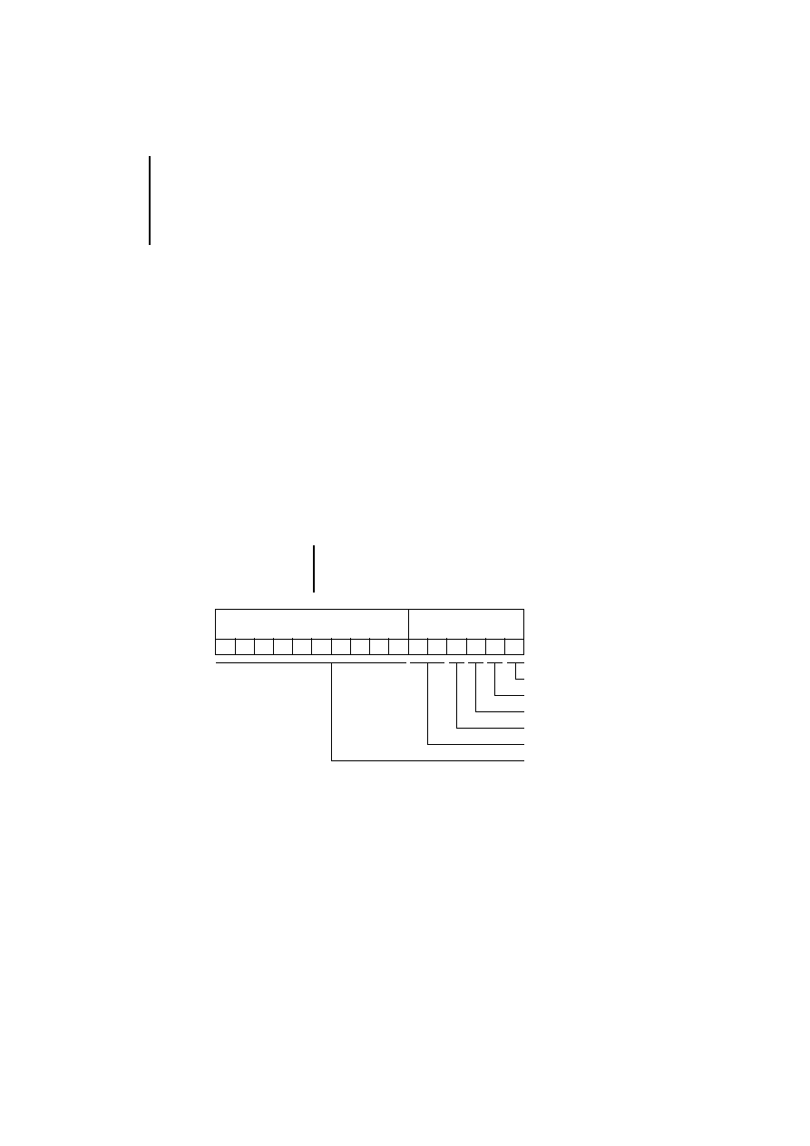
Extended diagnostics/device-specific
Standard slave
diagnostics
15 14 13 12 11 10
9
8
7
6
5
4
3
2
1
0
State 1
State 2
State 3
MasterAddress
Ident
Diagnostics

Function block
“PdpStationDiag”
59
09/99 AWB 2700-1368 GB
.
State1
Bit 0:
No response from station
Bit 1:
Station not ready for data transfer
Bit 2:
Station parameters incorrectly configured
Bit 3:
Station-specific diagnostic data is available
Bit 4:
Station has detected an unknown
command.
Bit 5:
Implausible response from station
Bit 6:
Incorrect configuration (e.g. ID number)
Bit 7:
Station parameters were configured by
another master
State2
Bit 0:
Station parameters not configured
Bit 1:
Static diagnosis
Bit 2:
Permanently set to 1
Bit 3:
Response monitoring active
Bit 4:
Freeze command active
Bit 5:
Sync command active
Bit 6:
Reserved
Bit 7:
PROFIBUS-DP configuration does not
contain the specified station
State3
Bit 0 to bit 6: reserved
Bit 7:
Extended station diagnostic data longer than
100 bytes
Testing/Commissioning/
Diagnostics
60
09/99 AWB 2700-1368 GB
Function block
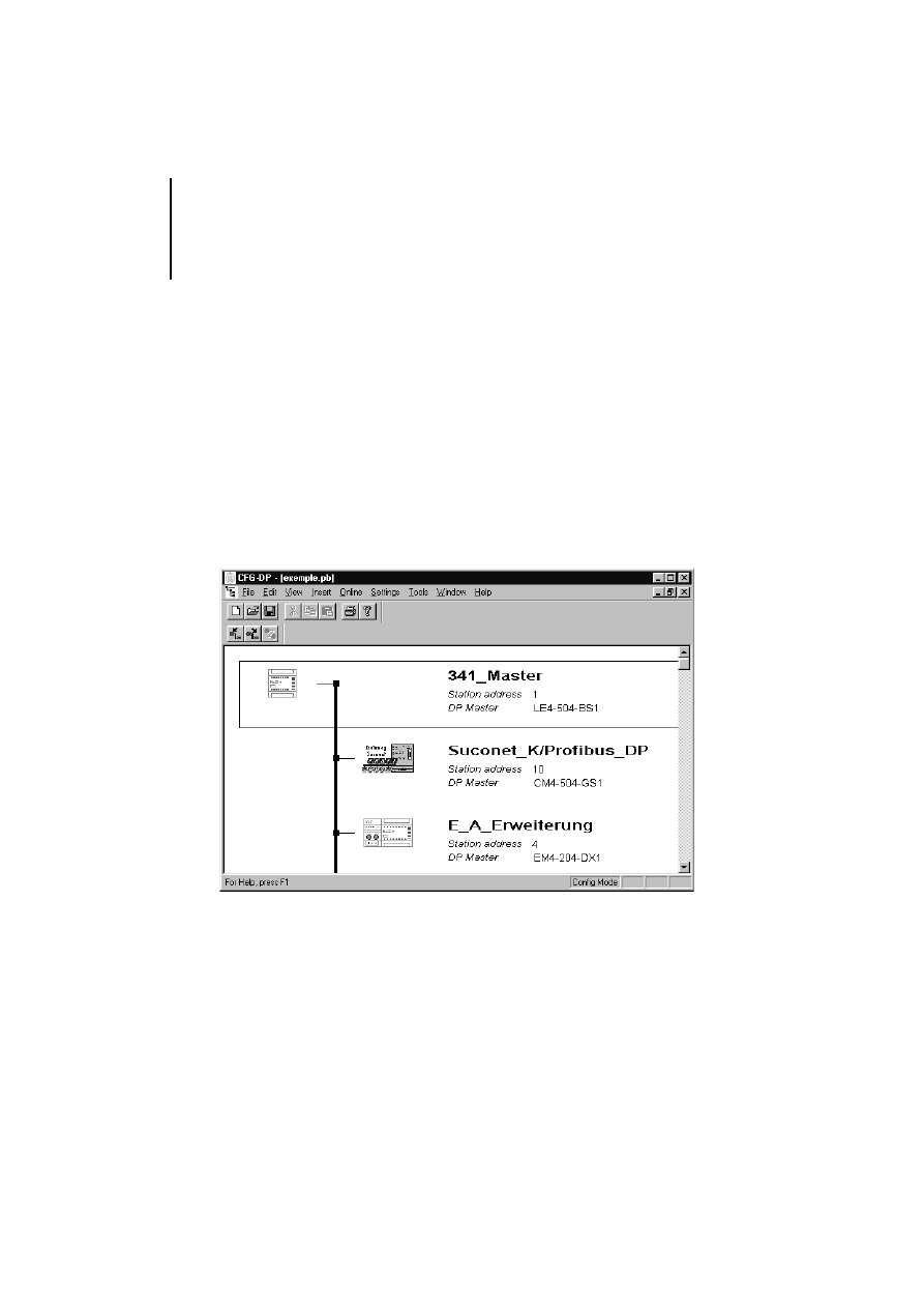
example
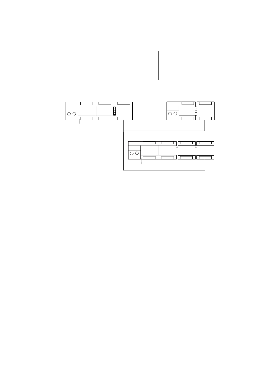
The example is for a PS 4-341-MM1 with an
LE 4-504-BS1 in slot 1, which manages the
PROFIBUS-DP line with two slave stations:
one CM 4-504-GS1 (gateway)
one EM 4-204-DX1 with local expansion modules
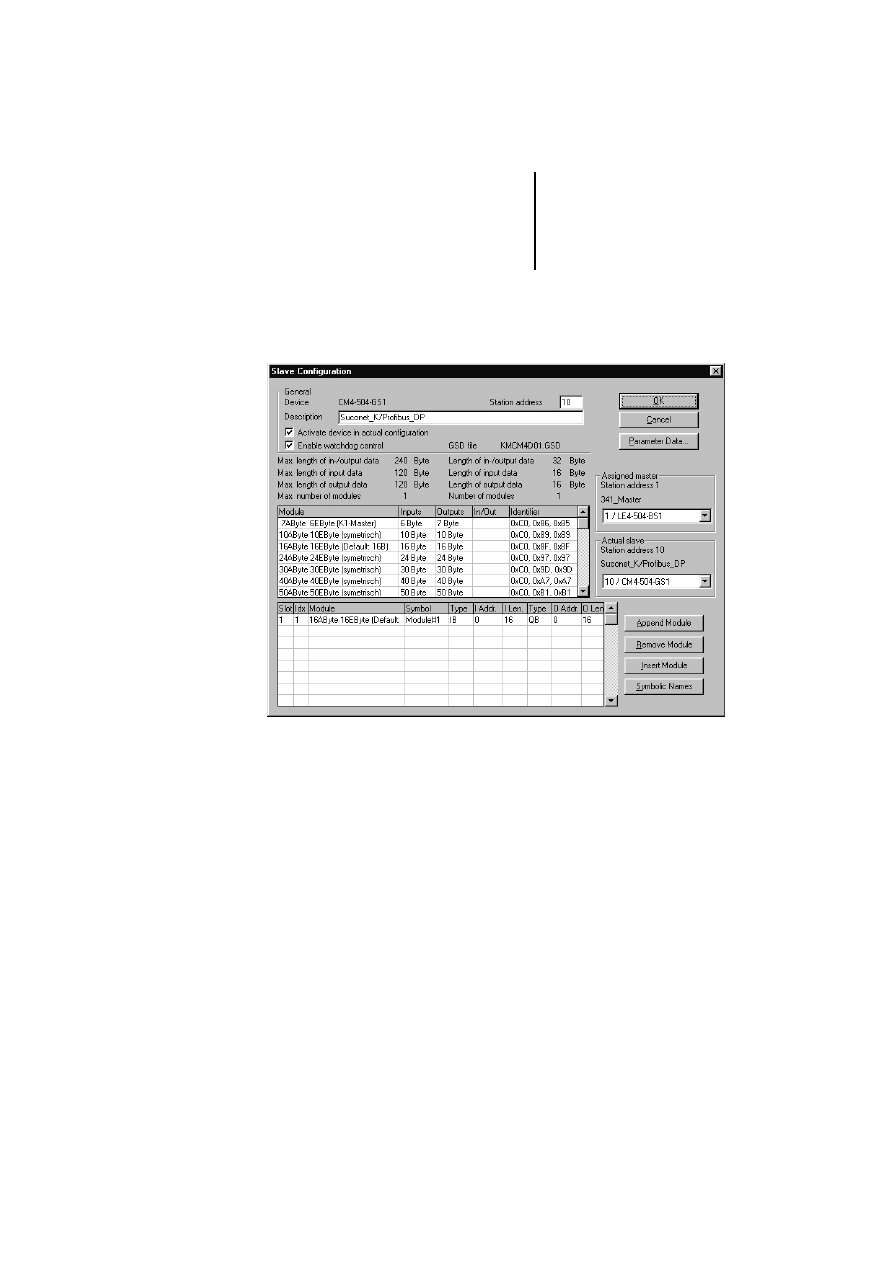
The two slave stations are added and their
parameters set in the PROFIBUS-DP configurator
CFG-DP. For details about operating the CFG-DP
configurator, refer to the electronic manual
AWB-EM 2700-1336 GB (PDF file for Acrobat
Reader), which is included on the Sucosoft S 40
CD-ROM.
Function block example
61
09/99 AWB 2700-1368 GB
To set the parameters of slave CM 4-504-GS1 with
station address 10, 16 bytes will be transferred in
each direction in this example.
Testing/Commissioning/
Diagnostics
62
09/99 AWB 2700-1368 GB
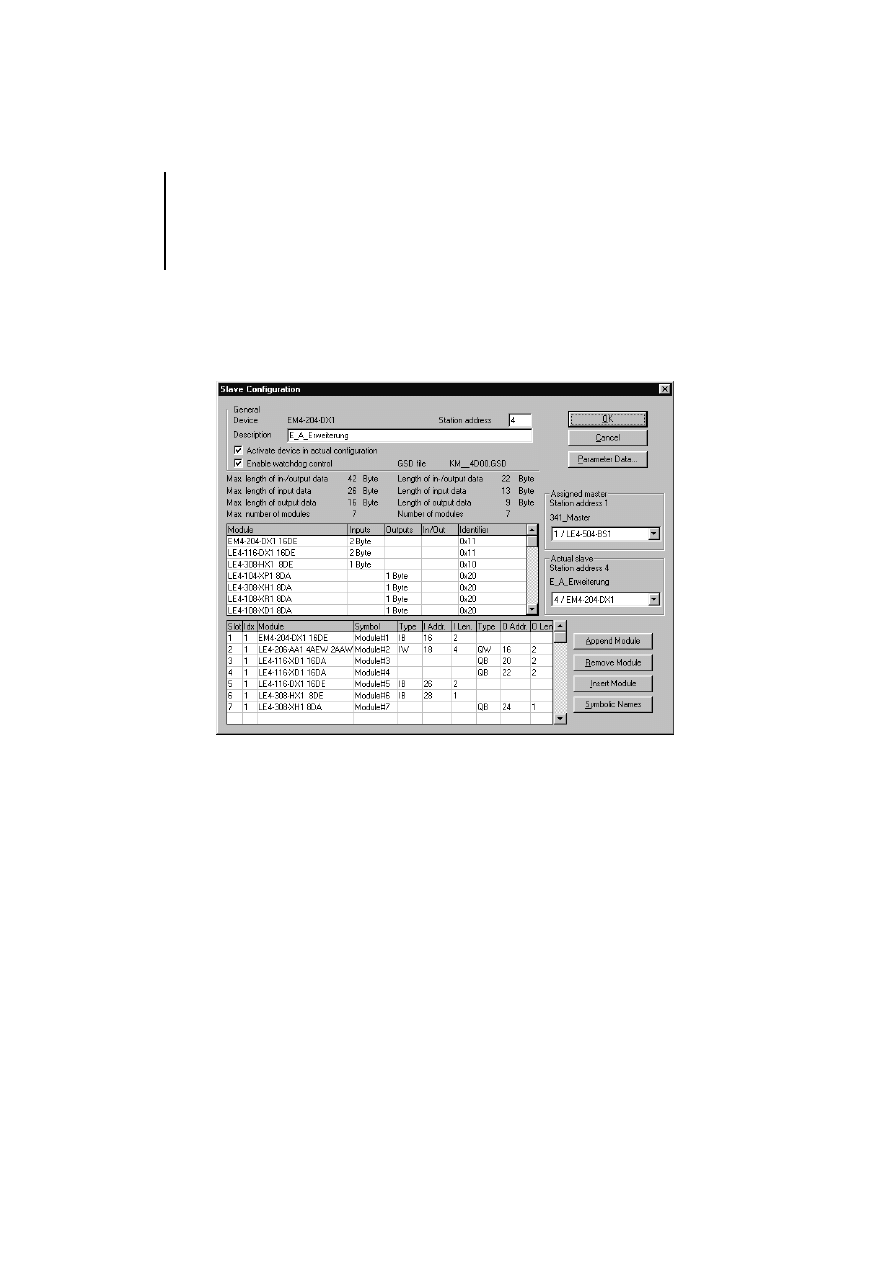
In the example, EM 4-204-DX1 with station
address 4 has a total of six local expansions,
including an LE 4-206-AA1 analog module in the first
position.
This configuration is stored and sent to network
module LE 4-504-BS1.
Function block example
63
09/99 AWB 2700-1368 GB
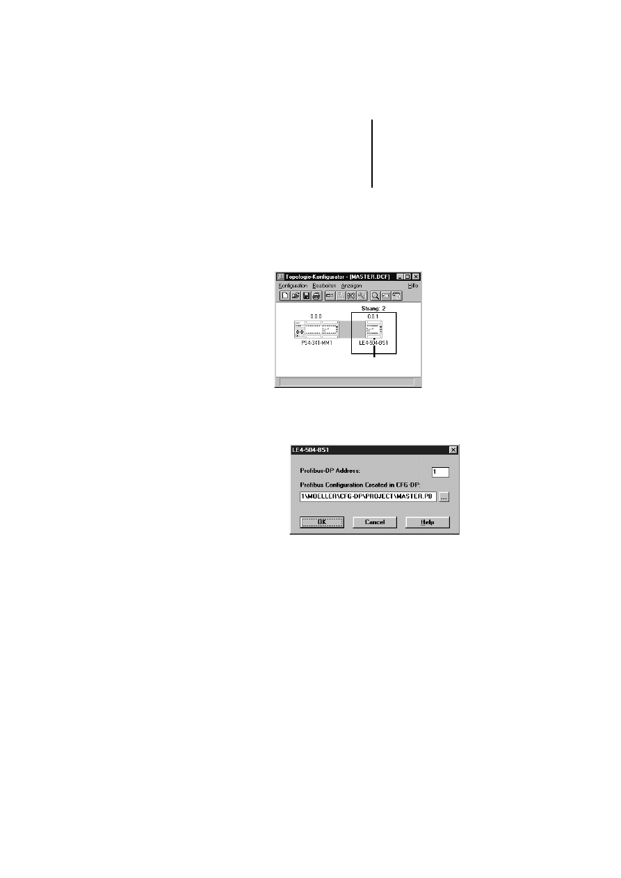
The topology configuration is then created in the
Sucosoft S 40 Topology Configurator. The
procedure for topology configuration is described in
manual AWB 2700-1305 GB “Sucosoft S 40, User
Interface”
왘 Select ‹Edit ➞ Set Parameters› and, in the dialog
that now opens, assign the PROFIBUS-DP
address for the LE 4-504-BS1.
왘 In the field “Profibus Configuration Created in
CFG-DP”, enter the path and name of the file
created with the CFG-DP PROFIBUS-DP
configurator or select the file with the button next
to the field.

Testing/Commissioning/
Diagnostics
64
09/99 AWB 2700-1368 GB
The reference to the PROFIBUS-DP configuration file
is required for consistency checks by the Sucosoft
user program.
The sample program below uses the topology
configuration created with Sucosoft S 40 to generate
an executable program for the PS 4-341-MM1,
which is then transferred to this PLC.
Beside an error analysis, you should implement the
following program sequences when working with the
function block.
The functions of the individual program sections are
listed below and are indicated by a corresponding
comment at the beginning of each section:
Registering all set diagnostic bits
Calling the function block for all registered
diagnostic bits
Entering the diagnostic data in a station-specific
buffer
Enabling the function block for a restart
Evaluating the diagnostic data
If a new or modified PROFIBUS-DP configuration
is loaded onto the LE 4-504-BS1 with the
CFG-DP, the user program of the PS 4-341-MM1
must be re-compiled with “Generate All” and
resent to the PS 4-341-MM1.

Function block example
65
09/99 AWB 2700-1368 GB
If diagnostic messages occur frequently and from
several stations at the same time, you should assign
priority to the function block call. This ensures that all
diagnostic data from the most important stations are
fetched.
The following example suggests a solution for the
function block whenever two stations send a
diagnosis at the same time. The solution guarantees
that each diagnostic message will be evaluated, even
if one of the stations continually sets the diagnostic
bit.
The master card always contains only the last
diagnostic message of a station. The diagnostic
bit remains set until the diagnostic data is
fetched by a function block call.

Testing/Commissioning/
Diagnostics
66
09/99 AWB 2700-1368 GB
Program DP_Diagnostics
VAR
(* Status, DP line; master in slot 1*)
DP_Status_line_1
AT %ISB0.0.1.0 :
BYTE;
(* DP---Line 2---Station 4---Module 0---EM4-204-DX1--- *)
(* Status byte, station 4 *)
Status_EM_4_204_ADR_4
AT %ISB2.4.0.0 :
BYTE;
em4204DX1_Modul0_IB0
AT %IB2.4.0.0 :
BYTE;
em4204DX1_Modul0_IB1
AT %IB2.4.0.1 :
BYTE;
le4206AA1_Modul1_IW0
AT %IW2.4.1.0 :
UINT;
le4206AA1_Modul1_IW2
AT %IW2.4.1.2 :
UINT;
le4206AA1_Modul1_IW4
AT %IW2.4.1.4 :
UINT;
le4206AA1_Modul1_IW6
AT %IW2.4.1.6 :
UINT;
le4206AA1_Modul1_QW0
AT %QW2.4.1.0 :
UINT;
le4206AA1_Modul1_QW2
AT %QW2.4.1.2 :
UINT;
le4116XD1_Modul2_QB0
AT %QB2.4.2.0 :
BYTE;
le4116XD1_Modul2_QB1
AT %QB1.4.2.1 :
BYTE;
le4116XD1_Modul3_QB0
AT %QB2.4.3.0 :
BYTE;
le4116XD1_Modul3_QB1
AT %QB2.4.3.1 :
BYTE;
le4116DX1_Modul4_IB0
AT %IB2.4.4.0 :
BYTE;
le4116DX1_Modul4_IB1
AT %IB2.4.4.1 :
BYTE;
le4308HX1_Modul5_IB0
AT %IB2.4.5.0 :
BYTE;
le4308XH1_Modul6_QB0
AT %QB2.4.6.0 :
BYTE;
(* DP---Line 2------Station 10--- GateWay--CM4-504-GS1--------- *)
(* Status byte, station 10 *)
Status_GateWay_ADR_10
AT %ISB2.10.0.0:
BYTE;
cm4504_IB0
AT %IB2.10.0.0 :
BYTE;
(* max. 16 bytes: 0 - 15 *)
cm4504_IB15
AT %IB2.10.0.15:
BYTE;
cm4504_QB0
AT %QB2.10.0.0 :
BYTE;
(* max. 16 bytes: 0 - 15 *)
cm4504_QB15
AT %QB2.10.0.15:
BYTE;

Function block example
67
09/99 AWB 2700-1368 GB
(*******************************************************************)
(*
Diagnosis of all line stations *)
(************************************************************************)
FB_DP_Diag
:
PDPSTATIONDIAG;
Strobe
:
BOOL;
FB_DP_Diag_F_Edge
:
F_TRIG;
DP_Diag
:
ARRAY[1..100] OF BYTE;
DP_Address
:
USINT;
DP_MASTERSLOT :
USINT;
GateWay_ADR_10_Diag
:
ARRAY[1..100] OF BYTE;
Buffer_Adr4
:
ARRAY[1..13] OF BYTE;
Buffer_Adr10
:
ARRAY[1..6] OF BYTE;
ADR4_Diag_Flag
:
BOOL;
ADR10_Diag_Flag
:
BOOL;
DiagCounter
:
USINT;
TestDiagBit_ADR4
:
FB_DiagBitCounter;
TestDiagBit_ADR10
:
FB_DiagBitCounter;
END_VAR
LD
DP_Status_Line_2(* Status byte DP *)
(* Evaluate DP line status byte*)
(*...*)
(* Status byte for DP station
*)
LD
Status_EM_4_204_ADR_4.6
(* Communication bit for station 4 *)
LD
Status_GateWay_ADR_10.6
(* Communication bit for station 10 *)
(* Evaluate communication bit *)
(*...*)
(** Begin ******************* Diagnostics Evaluation ********************************)
(***********************************************************************************)
(*
Register all set diagnostic bits
*)
(***********************************************************************************)
(* Diagnostic bit counter Addr.4 *)
CAL TestDiagBit_ADR4(
enable :=1,
InBit :=Status_EM_4_204_ADR_4.4
|
:=SetDiagBitCounter)
(* Diagnostic bit counter Addr.10 *)

Testing/Commissioning/
Diagnostics
68
09/99 AWB 2700-1368 GB
CAL TestDiagBit_ADR10(
enable :=1,
InBit :=Status_GateWay_ADR_10.4
|
:=SetDiagBitCounter)
(* Diagnostic detected then set diagnostic flags *)
LD
FB_DP_Diag.Active
EQ
1
JMPC
_DiagCall
(* Diagnostic request still active *)
LD
DiagCounter
(* Counter of detected diagnostic events *)
EQ
0
(* All diagnostics requests have been sent*)
JMPC
_ADR4
(* Entry of new diagnostic flags possible *)
JMP
_DiagSelect
(* Continue processing diagnostic flags *)
_ADR4:
(* Set diagnostic flag if ADR 4 reports diagnostic*)
LD
Status_EM_4_204_ADR_4.4
JMPCN
_ADR10
LD
DiagCounter
ADD
1
ST
DiagCounter
(* Increment diagnostic counter *)
LD
1
ST
ADR4_Diag_Flag
(* Set diagnostic flag for addr. 4*)
_ADR10:
(* (* Set diagnostic flag if ADR 10 reports diagnostic**)
LD
Status_GateWay_ADR_10.4
JMPCN
_ADRx
LD
DiagCounter
ADD
1
ST
DiagCounter
LD
1
ST
ADR10_Diag_Flag
(* (* Set diagnostic flag for Addr. 10 **)
_ADRx:
(*...*)

Function block example
69
09/99 AWB 2700-1368 GB
(***********************************************************************************)
(*
Function block call for all registered diagnostic bits*)
(***********************************************************************************)
_DiagSelect:
(* Process set diagnostic flags *)
LD
ADR4_Diag_Flag
JMPC
_prepareDiag_ADR4
LD
ADR10_Diag_Flag
JMPC
_prepareDiag_ADR10
JMP
_DiagCall
(* No diagnostic bit set *)
_prepareDiag_ADR4:
(* Enter parameters for diagnostics function block *)
LD
Status_EM_4_204_ADR_4.4
ST
FB_DP_Diag.Strobe
LD
4
ST
DP_Address
LD
1
ST
DP_MASTERSLOT
LD
0
ST
ADR4_Diag_Flag
JMP
_DiagCounter
_prepareDiag_ADR10:
LD
Status_GateWay_ADR_10.4
ST
FB_DP_Diag.Strobe
LD
10
ST
DP_Address
LD
1
ST
DP_MASTERSLOT
LD
0
ST
ADR10_Diag_Flag
JMP
_DiagCounter
_DiagCounter:(* Decrement diagnostic counter *)
LD
DiagCounter
SUB
1
ST
DiagCounter

Testing/Commissioning/
Diagnostics
70
09/99 AWB 2700-1368 GB
(***********************************************************************************)
(*
Function block call
*)
(***********************************************************************************)
_DiagCall:
CAL FB_DP_Diag(
STROBE :=,
MASTERSLOT :=DP_MASTERSLOT,
STATIONADDRESS :=DP_Address,
DIAGNOSE :=DP_Diag
|
:=ACTIVE,
:=STATE1,
:=STATE2,
:=STATE3,
:=MASTERADDRESS,
:=IDENT,
:=ERROR)
(* Evaluate falling edge of Active output *)
CAL FB_DP_Diag_F_Edge(
CLK :=FB_DP_Diag.Active
|
:=Q)
LD
FB_DP_Diag_F_Edge.Q
JMPCN
_DiagEnd
(* Falling edge detected *)
LD
FB_DP_Diag.Error
(* FB error detection *)
EQ
0
JMPC
_NoError
(* error-free *)
(*...*)
JMP
_DiagStrobe0
_NoError:
(* Enter diagnostic data in station diagnostics buffer *)
LD
DP_Address
EQ
4
JMPC
_DiagData_ADR4
LD
DP_Address
EQ
10
JMPC
_DiagData_ADR10
JMP
_DiagStrobe0

Function block example
71
09/99 AWB 2700-1368 GB
(***********************************************************************************)
(*
Enter diagnostic data in station-specific buffer*)
(***********************************************************************************)
_DiagData_ADR4:
(* Check master address and IdentNo. *)
LD
FB_DP_Diag.Masteraddress
LD
FB_DP_Diag.Ident
(*...*)
(* Enter diagnostic data in buffer *)
LD
FB_DP_Diag.STATE1
ST
Buffer_Adr4[1]
LD
FB_DP_Diag.STATE2
ST
Buffer_Adr4[2]
LD
FB_DP_Diag.STATE3
ST
Buffer_Adr4[3]
LD
DP_Diag[1]
ST
Buffer_Adr4[4]
LD
DP_Diag[2]
ST
Buffer_Adr4[5]
LD
DP_Diag[3]
ST
Buffer_Adr4[6]
LD
DP_Diag[4]
ST
Buffer_Adr4[7]
LD
DP_Diag[5]
ST
Buffer_Adr4[8]
LD
DP_Diag[6]
ST
Buffer_Adr4[9]
LD
DP_Diag[7]
ST
Buffer_Adr4[10]
LD
DP_Diag[8]
ST
Buffer_Adr4[11]
LD
DP_Diag[9]
ST
Buffer_Adr4[12]
LD
TestDiagBit_ADR4.SetDiagBitCounter
ST
Buffer_Adr4[13]
JMP
_DiagStrobe0

Testing/Commissioning/
Diagnostics
72
09/99 AWB 2700-1368 GB
_DiagData_ADR10:
(* Check master address and IdentNo. *)
LD
FB_DP_Diag.Masteraddress
LD
FB_DP_Diag.Ident
(*...*)
(* Enter diagnostic data in buffer *)
LD
FB_DP_Diag.STATE1
ST
Buffer_Adr10[1]
LD
FB_DP_Diag.STATE2
ST
Buffer_Adr10[2]
LD
FB_DP_Diag.STATE3
ST
Buffer_Adr10[3]
LD
DP_Diag[1]
ST
Buffer_Adr10[4]
LD
DP_Diag[2]
ST
Buffer_Adr10[5]
LD
TestDiagBit_ADR10.SetDiagBitCounter
ST
Buffer_Adr10[6]
JMP
_DiagStrobe0
(***********************************************************************************)
(*
Enable function block for a restart
*)
(***********************************************************************************)
_DiagStrobe0:
(* Output Strobe 0 after falling edge *)
CAL FB_DP_Diag(
STROBE :=0,
MASTERSLOT :=,
STATIONADDRESS :=,
DIAGNOSE :=DP_Diag)
_DiagEnd:
(***********************************************************************************)
(*
Evaluate diagnostic data
*)
(***********************************************************************************)
(*...*)
(** End ******************* Evaluate diagnostic data ********************************)

Function block example
73
09/99 AWB 2700-1368 GB
(***********************************************************************************)
(*
I-O Addressing of DP Stations
*)
(***********************************************************************************)
LD
16#FF
ST
le4116XD1_Modul2_QB1
(*...*)
_END:
END_PROGRAM
FUNCTION_BLOCK FB_DiagBitCounter
VAR_OUTPUT
SetDiagBitCounter:BYTE;
END_VAR
VAR_INPUT
enable
:
BOOL;
InBit
:
BOOL;
END_VAR
VAR
Set_Edge
:
R_TRIG;
END_VAR
LD
enable
JMPCN _End
(* Evaluate if bit was set *)
CAL Set_Edge(
CLK :=InBit
|
:=Q)
LD
Set_Edge.Q
EQ
1
JMPC
_SetBit
JMP
_End
(* Count occurrence of DiagBit *)
_SetBit:
LD
SetDiagBitCounter
BYTE_TO_USINT
ADD
1
USINT_TO_BYTE
ST
SetDiagBitCounter
_End:
END_FUNCTION_BLOCK

74
09/99 AWB 2700-1368 GB

75
09/99 AWB 2700-1368 GB
Appendix
Technical Data
Current consumption
max. 0.8 A (LE 4-504-BS1)
max. 0.5 A (LE 4-504-BT1)
Ambient temperature
(0 to 55) °C
Storage temperature
(–20 to 70) °C
Isolation voltage
850 V DC
Vibration resistance
1 g/(0...150) Hz
Shock resistance
15 g/11 ms
Degree of protection
IP 20
Weight
300 g
Connection type
Plug-in screw terminal, 9pole Sub-D
Connection cross-
sections for screw
terminal
flexible with ferrule 0.22 to 1.5 mm
2
(AWG 23 to AWG 16)
solid 0.22 to 2.5 mm
2
(AWG 23 to 13)
EMC
Interface
PROFIBUS-DP (EN 50 170, Vol. 2)
Station type
Master (Class 1)
(LE 4-504-BS1)
LE 4-504-BT1 (slave)
Electrical standard
RS 485
Isolation
Yes
Baud rate detection
automatic
Baud rate [kBit/s]
Cable lengths[m]
9.6
1200
19.2
1200
93.75
1200
187.5
1000
500
400
1500
200
3000
100
6000
100
12000
100

Appendix
76
09/99 AWB 2700-1368 GB
Accessories
Cable
ZB 4-900-KB1; specifically for PROFIBUS-DP
Connector
ZB 4-209-DS2; special PROFIBUS-DP up to
12 Mbit/s with switchable bus terminating
resistors
General EMC specifications for automation equipment
Emission
EN 55 011/22 Class A
Interference immunity
ESD
EN 61 000-4-2
Contact discharge
Air discharge
4 kV
8 kV
RFI
EN 61 000-4-3
AM/PM
10 V/m
Burst
EN 61 000-4-4
Mains/digital I/O
Analog I/O, fieldbus
2 kV
1 kV
Surge
EN 61 000-4-5
Digital I/O, asymmetrical
Mains DC, asymmetrical
Mains DC, symmetrical
Mains AC, asymmetrical
Mains AC, symmetrical
0.5 kV
1 kV
0.5 kV
2 kV
1 kV
Immunity to line-
conducted
interference
EN 61 000-4-6
AM
10 V
Dimensions
77
09/99 AWB 2700-1368 GB
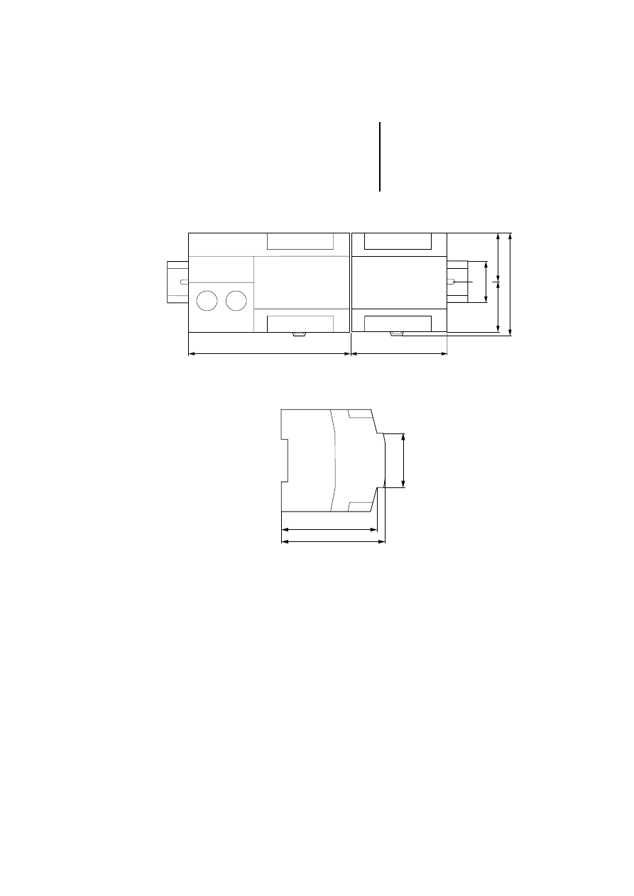
Dimensions
Figure 8: PS 4-200 with LE 4 on top-hat rail
Figure 9: PS 4, LE 4
42.5
LE 4
35
134.5
80.5
87.5
42.5
PS 4/EM 4
79
86
45
Appendix
78
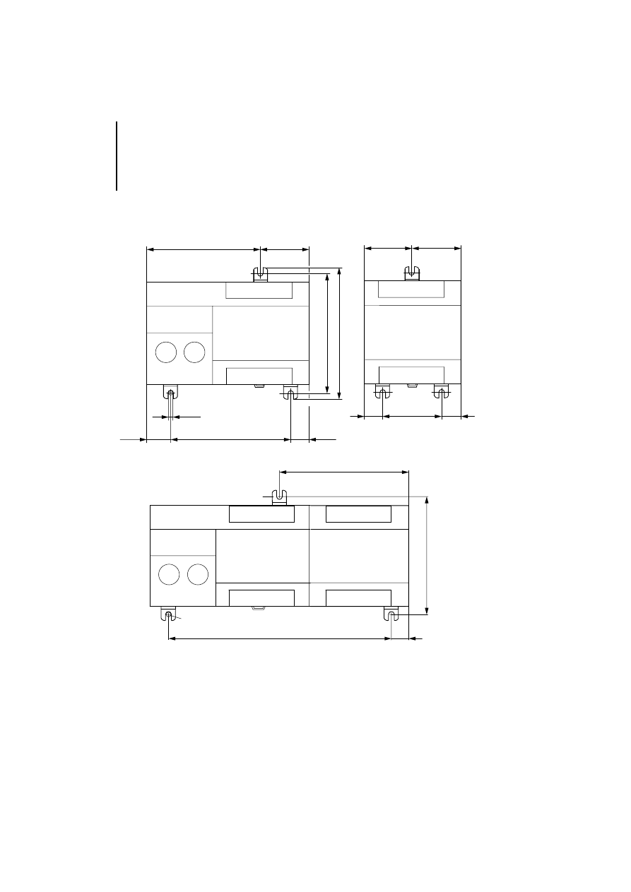
09/99 AWB 2700-1368 GB
Figure 10: PS 4-200, LE 4 and PS 4-341 with fixing
brackets
100
100
M4
94.25
40.25
19.25
15.25
PS 4/EM 4
110
⭋
50
LE 4
40.25
15.25
40.25
15.25
185
M 4
100
ZB 4-101-GF1
15.25
107.75

79
09/99 AWB 2700-1368 GB
Index
A
Active ............................................................................. 56
B
Bus terminating resistors ............................................... 23
C
CFG files ........................................................................ 25
CFG interface ................................................................. 17
Connecting
to CFG ........................................................................ 17
To PROFIBUS-DP ...................................................... 15
To the PS 4 ................................................................. 14
D
Diagnostics
Extended diagnostic bytes ......................................... 53
Function block PdpStationDiag ................................. 56
LE 4-504-BS1 ............................................................. 48
LE 4-504-BT1 ............................................................. 49
Operating system ....................................................... 46
Dimensions .................................................................... 77
E
EMC regulations .............................................................. 9
EMC requirements ........................................................... 9
Emission ........................................................................... 9
Engineering ...................................................................... 9
Error ............................................................................... 56
Error messages CPU .................................................... 46
Extended diagnostic byte .............................................. 53
F
Female connector .......................................................... 12
Function block PdpStationDiag
description .................................................................. 57
diagnostic data ........................................................... 56

Index
80
09/99 AWB 2700-1368 GB
Example ...................................................................... 60
Operands and their meaning ...................................... 56
Program DP_Diagnostics ............................................ 66
G
Grounding ....................................................................... 10
GSD files ......................................................................... 25
H
Hardware configuration .................................................. 23
I
Ident ............................................................................... 56
Immunity ........................................................................... 9
Interface
CFG ............................................................................. 17
PROFIBUS-DP ............................................................ 15
L
LED display .................................................................. 7, 8
In control cabinet ........................................................ 21
On fixing brackets ....................................................... 20
On top-hat rail ............................................................. 19
Mounting kit ZB 4-102-KS1 ........................................... 15
O
Operation ........................................................................ 35
Overview of diagnostic bytes ......................................... 45
P
Plug connector ............................................................... 12
Plug-in screw terminal ............................................ 7, 8, 12
PROFIBUS-DP cable ...................................................... 15
PROFIBUS-DP interface ................................................ 15
Programming cable ........................................................ 17
R
RS 485 interface ............................................................. 15

Index
81
09/99 AWB 2700-1368 GB
S
Screen grounding, analog cables .................................. 11
Screening ......................................................................... 9
Software configuration ................................................... 25
State 1 ............................................................................ 56
State 2 ............................................................................ 56
State 3 ............................................................................ 56
StationAddress .............................................................. 56
Status LEDs ................................................................... 44
Strobe ............................................................................ 56

Index
82
09/99 AWB 2700-1368 GB
Document Outline
- Contents
- About This Manual
- 1 About the local expansion modules
- 2 Engineering
- Electromagnetic compatibility (EMC)
- Bus and analog lines
- Attention! Electromagnetic interference
- Interference and line-conducted interference according to ENV50140 and ENV50141 can corrupt m...
- A faulty connection of the module may produce interference in other components.
- Attention!
- Ensure that all connections are corrosion proof and that the paint is removed from the connection...
- Connections
- a Female connector for connection to the PS4
- b Connection cross-sections: flexible with ferrule 0.22 to 1.5 mm2 (AWG23 to AWG16) solid 0.22...
- c Plug-in screw terminal A (green) = RxD/TxD-N receive/transmit data N B (red) = RxD/TxD-P receiv...
- d Plug connector for connecting further LEs
- e Switch for bus terminating resistors S1 and S2
- f PROFIBUS-DP interface; alternative connection for bus lines via 9-pin SubD socket with connect...
- g CFG interface (for LE4504BS1 only); connection for PC with CFG-DP configuration software via...
- h Terminal strip cover, for use with alternative connection method
- Figure 3: Connection overview
- Connecting to the PS4
- Due to the current consumption of the PROFIBUSDP LEs, there may be a limit to the expandability ...
- Table 1: Using the PROFIBUS-DP module
- 3 Mounting
- 4 Hardware Configuration
- 5 Software Configuration
- 6 Operation
- 7 Testing/Commissioning/Diagnostics
- Commissioning the LE4504BS1
- The exact procedure is described in the electronic documentation of the CFG-DP configurator, whic...
- The configuration of LE4-504-BS1 is only accepted by the PS 4-341-MM1 operating system during th...
- For fault correction or for a version update it may be necessary to load new firmware onto the LE...
- Commissioning the LE4504BT1
- Status indication in the operating phase
- Overview of diagnostic bytes
- a Data synchronization between PS4-341-MM1 andLE4504-BS1
- b Information about master LE4504-BS1; group informationfrom slaves
- c Byte0: information about status of slave LE4504-BT1; read by the slave CPU
- d Byte1: communication status of slave LE4504-BT1; read by the slave CPU
- e Extended byte1: information about slave CPU; master CPU reads operating status of slave CPU
- f Extended byte2: service information about slave CPU (e.g. state of backup battery)
- g General byte: indicator for extended diagnostic data from slave; read by the master CPU
- h Extended diagnostic message from slave; called by the master CPU
- CPU error messages
- Diagnostic byte of master module
- Slave module diagnostic bytes
- Function block “PdpStationDiag”
- Function block example
- VAR
- (* Status, DP line; master in slot 1*) DP_Status_line_1 AT %ISB0.0.1.0 : BYTE;
- (* DP---Line 2---Station 4---Module 0---EM4-204-DX1--- *) (* Status byte, station 4 *) Status_EM_...
- em4204DX1_Modul0_IB0 AT %IB2.4.0.0 : BYTE; em4204DX1_Modul0_IB1 AT %IB2.4.0.1 : BYTE;
- le4206AA1_Modul1_IW0 AT %IW2.4.1.0 : UINT; le4206AA1_Modul1_IW2 AT %IW2.4.1.2 : UINT; le4206AA1_M...
- le4206AA1_Modul1_QW0 AT %QW2.4.1.0 : UINT; le4206AA1_Modul1_QW2 AT %QW2.4.1.2 : UINT;
- le4116XD1_Modul2_QB0 AT %QB2.4.2.0 : BYTE; le4116XD1_Modul2_QB1 AT %QB1.4.2.1 : BYTE;
- le4116XD1_Modul3_QB0 AT %QB2.4.3.0 : BYTE; le4116XD1_Modul3_QB1 AT %QB2.4.3.1 : BYTE;
- le4116DX1_Modul4_IB0 AT %IB2.4.4.0 : BYTE; le4116DX1_Modul4_IB1 AT %IB2.4.4.1 : BYTE;
- le4308HX1_Modul5_IB0 AT %IB2.4.5.0 : BYTE;
- le4308XH1_Modul6_QB0 AT %QB2.4.6.0 : BYTE;
- (* DP---Line 2------Station 10--- GateWay--CM4-504-GS1--------- *) (* Status byte, station 10 *) ...
- cm4504_IB0 AT %IB2.10.0.0 : BYTE; (* max. 16 bytes: 0 - 15 *) cm4504_IB15 AT %IB2.10.0.15 : BYTE;
- cm4504_QB0 AT %QB2.10.0.0 : BYTE; (* max. 16 bytes: 0 - 15 *) cm4504_QB15 AT %QB2.10.0.15 : BYTE;
- (*******************************************************************) (* Diagnosis of all line st...
- FB_DP_Diag : PDPSTATIONDIAG; Strobe : BOOL;
- FB_DP_Diag_F_Edge : F_TRIG;
- DP_Diag : ARRAY[1..100] OF BYTE; DP_Address : USINT; DP_MASTERSLOT : USINT;
- GateWay_ADR_10_Diag : ARRAY[1..100] OF BYTE; Buffer_Adr4 : ARRAY[1..13] OF BYTE; Buffer_Adr10 : A...
- ADR4_Diag_Flag : BOOL; ADR10_Diag_Flag : BOOL; DiagCounter : USINT;
- TestDiagBit_ADR4 : FB_DiagBitCounter; TestDiagBit_ADR10 : FB_DiagBitCounter;
- END_VAR
- LD DP_Status_Line_2 (* Status byte DP *) (* Evaluate DP line status byte*) (*...*) (* Status byte...
- (* Evaluate communication bit *) (*...*)
- (** Begin ******************* Diagnostics Evaluation ********************************)
- (***********************************************************************************) (* Register...
- (* Diagnostic bit counter Addr.4 *) CAL TestDiagBit_ADR4( enable :=1, InBit :=Status_EM_4_204_ADR...
- LD DiagCounter (* Counter of detected diagnostic events *) EQ 0 (* All diagnostics requests have ...
- JMP _DiagSelect (* Continue processing diagnostic flags *)
- _ADR4: (* Set diagnostic flag if ADR 4 reports diagnostic*) LD Status_EM_4_204_ADR_4.4 JMPCN _ADR10
- LD DiagCounter ADD 1 ST DiagCounter (* Increment diagnostic counter *)
- LD 1 ST ADR4_Diag_Flag (* Set diagnostic flag for addr. 4*)
- _ADR10: (* (* Set diagnostic flag if ADR 10 reports diagnostic**) LD Status_GateWay_ADR_10.4 JMPC...
- LD DiagCounter ADD 1 ST DiagCounter
- LD 1 ST ADR10_Diag_Flag (* (* Set diagnostic flag for Addr. 10 **)
- _ADRx: (*...*)
- (***********************************************************************************) (* Function...
- _DiagSelect: (* Process set diagnostic flags *)
- LD ADR4_Diag_Flag JMPC _prepareDiag_ADR4 LD ADR10_Diag_Flag JMPC _prepareDiag_ADR10 JMP _DiagCall...
- _prepareDiag_ADR4: (* Enter parameters for diagnostics function block *)
- LD Status_EM_4_204_ADR_4.4 ST FB_DP_Diag.Strobe LD 4 ST DP_Address LD 1 ST DP_MASTERSLOT LD 0 ST ...
- JMP _DiagCounter
- _prepareDiag_ADR10:
- LD Status_GateWay_ADR_10.4 ST FB_DP_Diag.Strobe LD 10 ST DP_Address LD 1 ST DP_MASTERSLOT LD 0 ST...
- JMP _DiagCounter
- _DiagCounter: (* Decrement diagnostic counter *)
- LD DiagCounter SUB 1 ST DiagCounter
- (***********************************************************************************) (* Function...
- _DiagCall:
- CAL FB_DP_Diag( STROBE :=, MASTERSLOT :=DP_MASTERSLOT, STATIONADDRESS :=DP_Address, DIAGNOSE :=DP...
- (* Evaluate falling edge of Active output *) CAL FB_DP_Diag_F_Edge( CLK :=FB_DP_Diag.Active | :=Q)
- LD FB_DP_Diag_F_Edge.Q JMPCN _DiagEnd (* Falling edge detected *) LD FB_DP_Diag.Error (* FB error...
- _NoError: (* Enter diagnostic data in station diagnostics buffer *) LD DP_Address EQ 4 JMPC _Diag...
- LD DP_Address EQ 10 JMPC _DiagData_ADR10
- JMP _DiagStrobe0
- (***********************************************************************************) (* Enter di...
- _DiagData_ADR4: (* Check master address and IdentNo. *) LD FB_DP_Diag.Masteraddress LD FB_DP_Diag...
- LD DP_Diag[1] ST Buffer_Adr4[4] LD DP_Diag[2] ST Buffer_Adr4[5] LD DP_Diag[3] ST Buffer_Adr4[6]
- LD DP_Diag[4] ST Buffer_Adr4[7] LD DP_Diag[5] ST Buffer_Adr4[8] LD DP_Diag[6] ST Buffer_Adr4[9] L...
- LD TestDiagBit_ADR4.SetDiagBitCounter ST Buffer_Adr4[13]
- JMP _DiagStrobe0
- _DiagData_ADR10: (* Check master address and IdentNo. *) LD FB_DP_Diag.Masteraddress LD FB_DP_Dia...
- LD DP_Diag[1] ST Buffer_Adr10[4] LD DP_Diag[2] ST Buffer_Adr10[5]
- LD TestDiagBit_ADR10.SetDiagBitCounter ST Buffer_Adr10[6]
- JMP _DiagStrobe0
- (***********************************************************************************) (* Enable f...
- _DiagStrobe0: (* Output Strobe 0 after falling edge *)
- CAL FB_DP_Diag( STROBE :=0, MASTERSLOT :=, STATIONADDRESS :=, DIAGNOSE :=DP_Diag)
- _DiagEnd:
- (***********************************************************************************) (* Evaluate...
- (** End ******************* Evaluate diagnostic data ********************************)
- (***********************************************************************************) (* I-O Addr...
- LD 16#FF ST le4116XD1_Modul2_QB1 (*...*)
- _END: END_PROGRAM
- FUNCTION_BLOCK FB_DiagBitCounter VAR_OUTPUT SetDiagBitCounter : BYTE; END_VAR VAR_INPUT enable : ...
- (* Evaluate if bit was set *) CAL Set_Edge( CLK :=InBit | :=Q)
- LD Set_Edge.Q EQ 1 JMPC _SetBit
- JMP _End
- (* Count occurrence of DiagBit *) _SetBit:
- LD SetDiagBitCounter BYTE_TO_USINT ADD 1 USINT_TO_BYTE ST SetDiagBitCounter
- _End: END_FUNCTION_BLOCK
- Appendix
- Index
- Commissioning the LE4504BS1
- U2_g_si1.pdf
- H1368U1g.pdf
Wyszukiwarka
Podobne podstrony:
PS4 LE 4 206 AA2 h1331g
PS4 LE 4 622 CX1 h1324g
PS4 PS 416 NET 440, Master h1330g
dane mastertig2300mls
01 Certyfikat 650 1 2015 Mine Master RM 1 8 AKW M
h1239g PLC PS4 416
MasterPlanRekrutacjaGrupowa2010
2 3 Unit 1 Lesson 2 – Master of Your Domain
Mastercam creating 2 dimensio Nieznany
+le%9cmian+boles%b3aw+ +wiersze+wybrane 52RWPQJSPV3GXGTUE7QA4446RJVPT2XSKPEIAXY
504 - Kod ramki - szablon, RAMKI KOLOROWE DO WPISÓW
Mentalność-Le Goff, Materiały
Drgania i?le TEST B
Sylabus LE
Zadania ?le
Drgania i?le sprężyste praca klasowa
więcej podobnych podstron