
Hardware and Engineering
PS 416-NET-440, Master
PS 416-NET-441, Slave
PROFIBUS-DP Card
09/99 AWB 2700-1330 GB
1st published 1998, edition 04/98
© Moeller GmbH, Bonn
Author:
Jürgen Herrmann
Editor:
Karola Großpietsch
Translators: DK, Terence Osborn

Caution!
Dangerous electrical voltage!
Before commencing the installation
●
Disconnect the power supply of the
device.
●
Ensure that the device cannot be
accidentally restarted.
●
Verify isolation from the supply.
●
Earth and short circuit.
●
Cover or enclose neighbouring units that
are live.
●
Follow the engineering instructions
(AWA) of the device concerned.
●
Only suitably qualified personnel may
work on this device/system.
●
Before installation and before touching
the device ensure that you are free of
electrostatic charge.
●
Connecting cables and signal lines
should be installed so that inductive or
capacitive interference do not impair the
automation functions.
●
Install automation devices and related
operating elements in such a way that
they are well protected against
unintentional operation.
●
Suitable safety hardware and software
measures should be implemented for
the I/O interface so that a line or wire
breakage on the signal side does not
result in undefined states in the
automation devices.
●
Ensure a reliable electrical isolation of
the low voltage for the 24 volt supply.
Only use power supply units complying
with IEC 60 364-4-41 or HD 384.4.41 S2.
●
Deviations of the mains voltage from the
rated value must not exceed the
tolerance limits given in the
specifications, otherwise this may cause
malfunction and dangerous operation.
●
Emergency stop devices complying with
IEC/EN 60 204-1 must be effective in all
operating modes of the automation
devices. Unlatching the emergency-stop
devices must not cause uncontrolled
operation or restart.
●
Devices that are designed for mounting
in housings or control cabinets must only
be operated and controlled after they
have been installed with the housing
closed. Desktop or portable units must
only be operated and controlled in
enclosed housings.
●
Measures should be taken to ensure the
proper restart of programs interrupted
after a voltage dip or failure. This should
not cause dangerous operating states
even for a short time. If necessary,
emergency-stop devices should be
implemented.
IBM is a registered trademark of International
Business Machines Corporation.
All other brand and product names are
trademarks or registered trademarks of the
owner concerned.
All rights reserved, including those of the
translation.
No part of this manual may be reproduced in
any form (printed, photocopy, microfilm or
any otherprocess) or processed, duplicated
or distributed by means of electronic
systems without written permission of
Moeller GmbH, Bonn.
Subject to alterations without notice.

II
09
/99
A
W
B 27-
13
30 G
B
List of revisions for the manual AWB 27-1300 GB
Modification date Page
Description
New
Modifica-
tion
Remove
09/99
Complete
manual
PS 416-NET-441 (Slave)
҂

1
09
/99
A
W
B
270
0-
1330
G
B
Contents
Contents 3
Additional documentation
Purpose 5
Hardware and software requirements
Electromagnetic compatibility (EMC)
Fitting and removing
cards 17
Connecting the card
Configuring the PS 416-NET-440

Contents
2
09
/99
A
W
B
270
0-
1330
G
B
Testing/Commissioning/Diagnostics
Commissioning the PS 416-NET-440
Commissioning the PS 416-NET-441
Status indication in the operating phase
Diagnostic byte of the master card

3
09
/99
A
W
B
270
0-
1330
G
B
About This Manual
Contents
The PS 416-NET-440 and PS 416-NET-441 cards
are the interface from the PS 416-PLC to
PROFIBUS-DP. This manual describes hardware
and engineering as well as the test and
commissioning functions for these cards.
The PS 416-NET-441 slave card is configured with
the Sucosoft S 40 Topology Configurator. For
configuring the PS 416-NET-440 master card use
the Sucosoft S 40 Topology Configurator and the
PROFIBUS-DP configurator CFG-DP.
Additional
documentation
The PROFIBUS configurator is described in detail in
the electronic manual AWB-EM 2700-1336 GB. This
is a PDF file supplied with the configurator on the
Sucosoft S 40 CD-ROM.
For detailed information about the Sucosoft S 40
Topology Configurator, refer to the manual “S 40
User Interface” (AWB 2700-1305 GB).
About This Manual
4
09
/99
A
W
B
270
0-
1330
G
B
Symbols
The symbols used in this manual have the following
meaning:
왘 Indicates handling instructions.
!
Indicates useful tips and additional information.
Note
Warns of the possibility of damage to products,
adjacent equipment or data.
Caution!
Warns of the possibility of serious damage to
products, adjacent equipment or data and risk of
serious or fatal personal injury.

5
09
/99
A
W
B
270
0-
1330
G
B
1
About the Cards
General information
The PS 416-NET-440 and PS 416-NET-441 cards
form the interface between the PS 416 and the
PROFIBUS-DP field bus, the industry standard
based on EN 50 170 Vol. 2.
Purpose
PS 416-NET-440
This card provides the master function for the
PROFIBUS-DP field bus. It manages and handles the
exchange of data between the user program on the
PS 416 and the connected slaves. A maximum of
125 slaves can be addressed; without repeater, up
to 30.
This card also provides numerous diagnostic
options.
PS 416-NET-441
The slave card is required for connecting a PS 416
PLC to the PROFIBUS-DP field bus. It manages and
handles data exchange between the user program of
the PS 416 and one or more connected network
masters.
It, too, provides diagnostic data.

About the Cards
6
09
/99
A
W
B
270
0-
1330
G
B
Hardware and software
requirements
The table presents an overview of the hardware and
software requirements for operating the
PS 416-NET-440 and PS 416-NET-441 cards in the
PS 416 PLC.
The device configuration files (*.GSD) for the cards
are included in the CFG-DP configuration software.
If other manufacturers’ devices are used, the
required files are available from Moeller’s service
mailbox and website and from the PROFIBUS User
Organization (PNO):
Analog modem +49 228 6021414
ISDN
+49 228 6021881
http://www.moeller.net/automation
http://www.profibus.com
PS 416-NET-440
PS 416-NET-441
Rack
PS 416-BGT-400/-410/-420
PS 416-BGT-421
(with potential equalization bar)
PS 416-ZBX-401/-402/-403
CPU
PS 416-CPU-x00 (in the basic unit)
Power supply
PS 416-POW-400/-410/-420
Sucosoft S 40
from version 2.1
from version 4.0
Operating system for
PS 416-CPU-x00
from version 2.1
from version 4.0
CFG-DP configuration
software
from version 1.0
–
Setup of PS 416-NET-440
7
09
/99
A
W
B
270
0-
1330
G
B
Setup of
PS 416-NET-440
Figure 1: .PROFIBUS-DP card PS 416-NET-440
LEDs
CFG interface
Protective cap for the CFG interface
PROFIBUS-DP interface
P
R
O
F
I
B
U
S
-
D
P
network
PROFIBUS-DP
0100018
run
ready
status
error
NET-440
C
F
G
B
U
S
P
R
O
F
I

About the Cards
8
09
/99
A
W
B
270
0-
1330
G
B
Notes on the PS 416-NET-440
LEDs
The four LEDs indicate the status of the card and the
complete PROFIBUS-DP bus (see Chapter 6,
Page 37):
the red LED indicates error conditions
the green LED indicates error-free operation
the yellow LEDs provide information about the
status of the card
CFG interface
The 9-pin subminiature connector is used to connect
a PC to the CFG-DP configuration software
(see Chapter 2, Page 12).
Protective cap
If the CFG interface is not used during operation of
the PS 416-NET-440, the connector must be fitted
with the protective cap to prevent electrostatic
interference.
PROFIBUS-DP interface
The 9-pin subminiature connector is used for
connecting the card to the PROFIBUS-DP field bus
(see Chapter 2, Page 12).
Setup of PS 416-NET-441
9
09
/99
A
W
B
270
0-
1330
G
B
Setup of
PS 416-NET-441
Figure 2: PROFIBUS-DP card PS 416-NET-441
LEDs
PROFIBUS-DP interface
network
PROFIBUS-DP
0100018
B
U
S
P
R
O
F
I
bus
diag
config-
error
NET
-441

About the Cards
10
09
/99
A
W
B
270
0-
1330
G
B
Notes on the PS 416-NET-441
LEDs
The three LEDs indicate the status of the card and
the complete PROFIBUS-DP bus (see Chapter 6,
Page 37):
the red LED indicates error conditions
the green LED indicates error-free operation
the yellow LED provides information about the
status of the card
PROFIBUS-DP interface
The 9-pin subminiature connector is used for
connecting the card to the PROFIBUS-DP field bus
(see Chapter 2, Page 11).

11
09
/99
A
W
B
270
0-
1330
G
B
2
Configuration
Electromagnetic
compatibility (EMC)
For information about laying cables and screening,
please refer to manual AWB 27-1287-GB “EMC –
Engineering Guidelines for Programmable
Controllers”.
Number of cards and
slots
The PS 416-NET-440 master and PS 416-NET-441
slave cards can be used in all basic units (racks with
CPU).
PS 416-NET-440
This card requires two slots and can be placed in any
of the slots to the right of the CPU. A maximum of
seven PS 416-NET-440 cards can be fitted. Be sure
to calculate the required electrical power (from
Sucosoft S 40 V 4.0, this is done automatically by the
Topology Configurator).
PS 416-NET-441
This card requires one slot and can be placed in any
of the slots to the right of the CPU. To determine the
possible number of cards, you must calculate the
required electrical power.
PROFIBUS-DP
interface
The cards are connected to the PROFIBUS-DP field
bus via an isolated RS-485 interface, which is
located on the front of the PS 416-NET-440 or the
PS 416-NET-441 in the form of a female Sub-D
connector.
!
Use the special PROFIBUS-DP connector
ZB 4-209-DS2, which contains the circuitry
required for interference-free operation up to a
transfer speed of 12 Mbit/s.
Configuration
12
09
/99
A
W
B
270
0-
1330
G
B
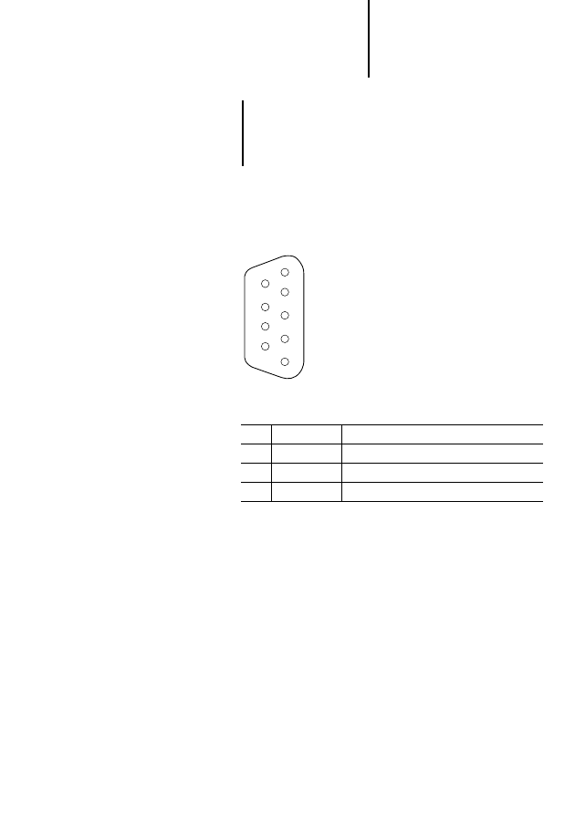
Connection assignment
The PROFIBUS-DP bus interface is a 9-pin male
Sub-D connector.
Figure 3: PROFIBUS-DP pin assignment
CFG interface
The PS 416-NET-400 card is connected to a PC
running the CFG-DP configuration software via an
RS 232 C interface (COM). The port is a female Sub-
D connector, located on the front of the
PS 416-NET-440. The PS 416-ZBK-210
programming cable can be used to make the
connection.
Pin
Designation
Meaning
3
RxD/TxD-P
Transmit/receive data line, positive
5
DGND
Data ground
6
VP
Supply voltage +5 V
8
RxD/TxD-N
Transmit/receive data line, negative
6
7
8
9
2
3
4
5
1
Wiring and cabling
13
09
/99
A
W
B
270
0-
1330
G
B
Connection assignment
The CFG interface is a 9-pin male Sub-D connector.
Figure 4: CFG connector pin assignment
Wiring and cabling
Connecting the cards
The PS 416-NET-440 and -441 communicate with
the connected stations via the PROFIBUS-DP field
bus. The data transmission medium for the
PROFIBUS-DP field bus is the screened ZB 4-900-
KB1 two-wire cable. This cable is supplied in 100 m
rolls and must be configured and fitted with
ZB 4-209-DS2 connectors by the user.
!
If the CFG port is not used during operation of the
card, the connector must be fitted with the
protective cap to prevent electrostatic
interference.
Pin
Designation
Meaning
2
RxD
Receive data
3
TxD
Transmit data
5
DGND
Data ground
6
7
8
9
2
3
4
5
1

Configuration
14
09
/99
A
W
B
270
0-
1330
G
B
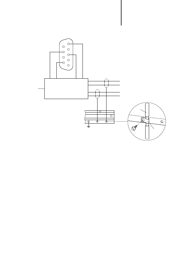
왘 To connect the card to the network’s PROFIBUS-
DP line, use the ZB 4-209-DS2 data plug.
왘 To fit the screen, remove a section of insulation
from all PROFIBUS cables.
왘 Attach the cable with the ZB 4-102-KS1 screen to
the potential equalization bar (see Fig. 5).
왘 If the PS 416-NET-440 or PS 416-NET-441 is the
first or last station on the line, switch the bus
terminating resistors on the data plug on by
turning the switch to ON.
Connecting stations
왘 Use a suitable data plug (e.g. a ZB 4-209-DS2 for
the 9-pin Sub-D connector) to connect the
stations to the network’s PROFIBUS-DP line.
왘 To fit the screen, remove a section of insulation
from all PROFIBUS cables.
왘 Attach the cable with the ZB 4-102-KS1 screen to
the potential equalization bar (see Fig. 5).
왘 If the station is located at the beginning or end of
the network’s PROFIBUS-DP line, switch the bus
terminating resistors on.
Wiring and cabling
15
09
/99
A
W
B
270
0-
1330
G
B
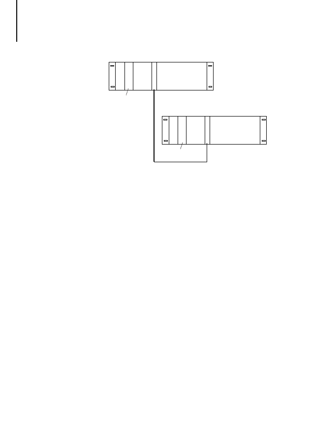
Figure 5: Screening the data cable
PROFIBUS-DP data plug ZB 4-209-DS2
PROFIBUS-DP cable ZB 4-900-KB1
Screen ZB 4-102-KS1
B
A
A
B
PROFIBUS
DGND
9
5
4
3
2
1
8
7
6
VP
(+5 V)
RxD/TxD-N
RxD/TxD-P
RxD/
TxD-P
PS 416-ZBX-40x
RxD/TxD-N
RxD/TxD-P
RxD/TxD-N
M4
⫻8

Configuration
16
09
/99
A
W
B
270
0-
1330
G
B
Connecting the PC to the PS 416-NET-440
To configure the PS 416-NET-440 with the CFG-DP
configuration software, connect the PC to the card
using the preassembled PS 416-ZBK-210 cable.
The cable is 2 m long. If this is not enough, you can
assemble your own cable using the PS 416-ZBS-411
and PS 416-ZBS-410 data plugs. The cable must be
no longer than 15 m.
Power supply
The power supply module PS 416-POW-4x0
internally supplies the cards with 5 V DC via the
rack’s system bus.
The card’s current consumption is:
PS 416-NET-440: max. 0.8 A
PS 416-NET-441: max. 0.5 A
To prevent errors during startup of PROFIBUS-DP,
set the system’s power supply up so that the
connected remote stations on the PROFIBUS-DP
line of the PS 416-NET-440 are switched on
simultaneously by the PS 416 PLC.

17
09
/99
A
W
B
270
0-
1330
G
B
3
Installation
Fitting and removing
cards
Use the master and slave cards only in a basic unit
(rack with CPU).
In the rack, the
PS 416-NET-440 occupies two slots, and the
PS 416-NET-441 occupies one slot.
The PS 416-NET-440 and PS 416-NET-441 cards
can be installed in any slot of the basic unit to the
right of the power supply and the CPU.
왘 Slide the card into the rack until it snaps into
place.
왘 Tighten the fixing screws.
Removal of the cards is in reverse order.
Caution!
Do not remove or insert cards when live.
Before touching the card, free yourself of
electrostatic charge.
Voltage peaks at the bus connector can lead to
faults and can damage the card.

Installation
18
09
/99
A
W
B
270
0-
1330
G
B
Connecting the card
왘 Make the connections to the PROFIBUS-DP
configurator CFG-DP (for PS 416-NET-440 only)
and to the PROFIBUS-DP field bus (see
Chapter 2, Page 13).
왘 Use the screws on the data plugs to secure them
to the card.
!
If the CFG port is not used during operation of the
card, the connector must be fitted with the
protective cap to prevent electrostatic
interference.
19
09
/99
A
W
B
270
0-
1330
G
B
4
Software Configuration
Configuring the
PS 416-NET-440
To configure the PS 416-NET-440 card, use the
Sucosoft S 40 Topology Configurator and the
PROFIBUS CFG-DP configurator.
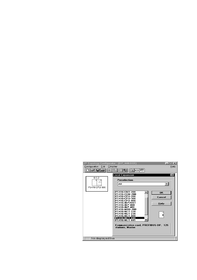
Sucosoft Topology Configurator
In the Sucosoft S 40 Topology Configurator, specify
all cards used in the PS 416.
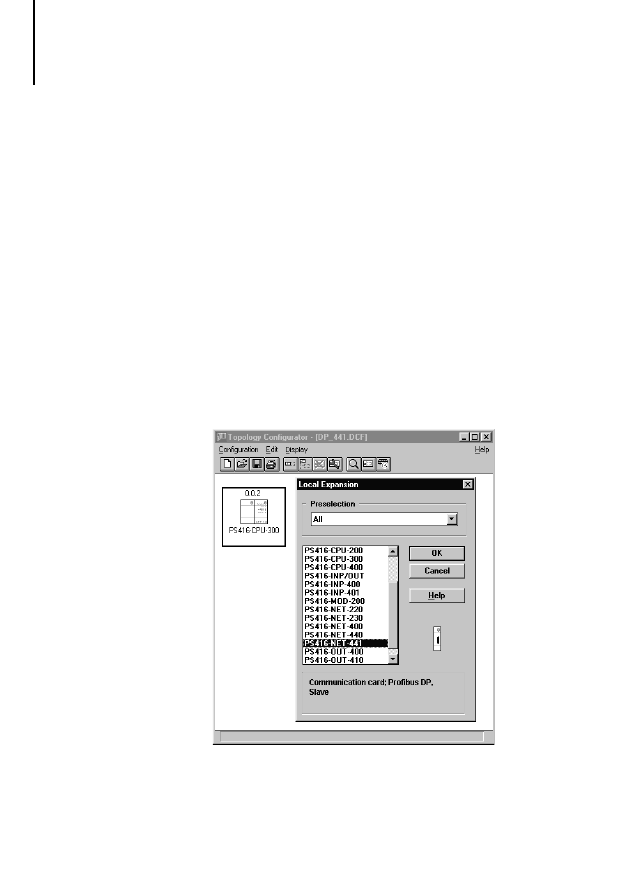
왘 In Sucosoft S 40, start the Topology
Configurator.
왘 Create a new topology configuration with a
PS 416-CPU-x00, or load an existing topology
configuration for a PS 416 with an operating
system version 2.1 or higher.
왘 Mark the card next to which you want to insert the
PS 416-NET-440, and click on the Local
Expansion button.
Software Configuration
20
09
/99
A
W
B
270
0-
1330
G
B
왘 From the list of available cards, select the
PS 416-NET-440 and confirm with OK. A Suconet
K line number is then assigned to the
PROFIBUS-DP line (max. 9 lines). The
PROFIBUS-DP slaves are specified and
parameterized in the PROFIBUS-DP configurator
CFG-DP.
왘 When you have configured all PS 416 cards, save
the configuration file.
!
Seven PS 416-NET-440 cards can be inserted in
each rack. Be sure to calculate the required
electrical power (from Sucosoft S 40 V 4.0, this is
done automatically by the Topology
Configurator).

Configuring the
PS 416-NET-440
21
09
/99
A
W
B
270
0-
1330
G
B
PROFIBUS-DP Configurator
With the CFG-DP configurator, you can
transfer new firmware versions to the
PS 416-NET-440
configure the PS 416-NET-440 and set the bus
parameters for PROFIBUS-DP
parameterize slave stations and assign them to
the PROFIBUS-DP master cards
assign slave stations to groups that respond to
the PROFIBUS-DP command “global control”
(e.g. SYNC or FREEZE)
print the configuration you have created
load the created configuration to the
PS 416-NET-440
monitor and diagnose the PS 416-NET-440 and
the assigned network line with its stations
start and stop communication in the network line
of the PS 416-NET-440
For a detailed description of the CFG-DP
Configurator and its operation, refer to the electronic
manual AWB-EM 2700-1336 GB. The manual (PDF
file) and the configurator are supplied with the
Sucosoft S 40 software.
Caution!
Do not interrupt firmware transmission as this
prevents subsequent access to the card.
Software Configuration
22
09
/99
A
W
B
270
0-
1330
G
B
Configuring the
PS 416-NET-441
To configure the PS 416-NET-441 card, use the
Sucosoft S 40 Topology Configurator.
Sucosoft Topology Configurator
In the Sucosoft S 40 Topology Configurator, specify
all cards that are used in the PS 416.
왘 In Sucosoft S 40, start the Topology
Configurator.
왘 Create a new topology configuration with a
PS 416-CPU-x00, or load an existing topology
configuration for a PS 416 with an operating
system version 4.0 or higher.
왘 Mark the card next to which you want to insert the
PS 416-NET-440, and click on the Local
Expansion button.
Configuring the
PS 416-NET-441
23
09
/99
A
W
B
270
0-
1330
G
B
왘 From the list of available cards, select the
PS 416-NET-441 and confirm with OK.
왘 When you have configured all PS 416 cards, save
the configuration file.
!
The number of PS 416-NET-441 cards that can
be used is determined by the power of the power
supply card. A power test is performed
automatically in the Sucosoft S 40 Topology
Configurator.
Software Configuration
24
09
/99
A
W
B
270
0-
1330
G
B
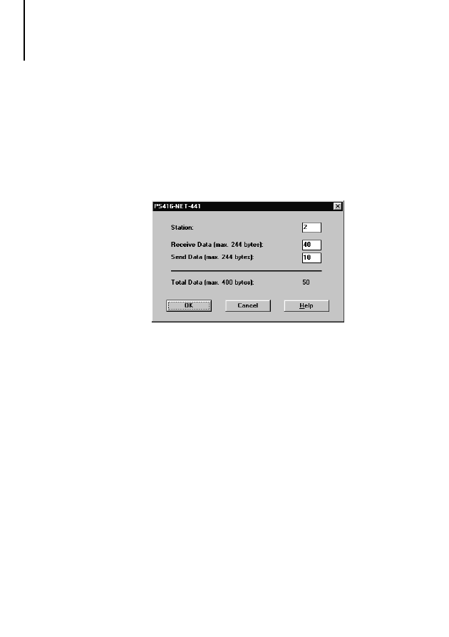
Defining send and receive data parameters
왘 Open the Parameters window by double-clicking
the PS 416-NET-441 card in the current topology
configuration.
or
왘 Mark the card in the current topology
configuration and select ‹Edit
➞ Set
Parameters...›.
In the Station field, define the address to be assigned
to the PS 416-NET-441 as slave on the
PROFIBUS-DP line. Valid addresses are 0 to 125 (0
is reserved for diagnostics and should therefore be
avoided). The entered address and the address in the
configuration of the master for the PROFIBUS-DP
line of the PS 416-NET-441 must be the same.
왘 In the Receive Data field, enter the number of
bytes that the slave PS 416-NET-441 is to receive
from the line master. You can either select a
figure from the list of predefined values or enter a
value directly in the field.

Configuring the
PS 416-NET-441
25
09
/99
A
W
B
270
0-
1330
G
B
왘 In the Send Data field, enter the number of bytes
that the PS 416-NET-441 is to send to the line
master. You can either select a figure from the list
of predefined values or enter a value directly in
the field.
왘 Confirm your inputs with OK.
왘 When you have configured all PS 416 cards, save
the file.
!
Always define send and receive data from the
point of view of the device (CPU) for which the
configuration is being created. The inputs made
here must be the same as the corresponding
parameter settings in the master’s
PROFIBUS-DP configurator.
If the master’s PROFIBUS-DP configurator
permits free lengths, you can enter any value from
0 and 244 for send and receive data. Otherwise,
you must select a value from the list. The listed
lengths correspond with those that are defined in
the device’s GSD file. These values can therefore
be defined with any standard-compliant
PROFIBUS-DP configurator. The sum of all send
and receive data must not exceed 400.

26
09
/99
A
W
B
270
0-
1330
G
B

27
09
/99
A
W
B
270
0-
1330
G
B
5
Operation
Addressing the cards
PROFIBUS-DP cards
Moeller’s 5-digit notation is used for reading and
writing in the PROFIBUS-DP network line. A
mirroring procedure is used to access the data. At
the beginning of each program cycle, the input
values are read from the dual-port RAM of the
PS 416-NET-440/-441, and at the end of the
program cycle, the output values are written to the
dual-port RAM of the PS 416-NET-440/-441.
The I/O data can be accessed by bit, byte, word, or
double word.
The data is assigned to the user program variables
when the variables are declared in the user program
by Sucosoft S 40.
The address notation assignment corresponds with
the notation for Suconet K:
<Line No.> . <Station No.> . <Module No.> . <Byte/Word/Double word> . <Bit>
Operand:
I, Q (master); RD, SD (slave)
Data width: X, B, W, D
For addressing slave card PS 416-NET-441, the first
two places of the address –
<Line No.>
and
<Station
No.>
– are always “0” (zero). The third place defines
the slot in which the card is located.
Operation
28
09
/99
A
W
B
270
0-
1330
G
B
The master declares the input and output data in
packets as separate modules in the PROFIBUS-DP
configuration, even if the network station consists of
only one physical module. The input and output data
is addressed through different module numbers.
A user program may therefore contain different
numbers for input and output data in the third place
of the five-digit address.
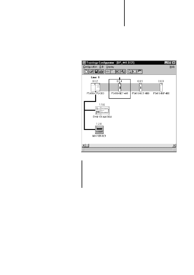
Example:
Slave PS 416-NET-441 is connected to line 1 and
has 10 input bytes and 10 output bytes.

Addressing the cards
29
09
/99
A
W
B
270
0-
1330
G
B
The output data from the slave is shown in the lower
list box, labelled “Module#2”, and will be read by
master PS 416-NET-440 with address operators
%IB1.7.1.0 to %IB1.7.1.9.
The slave input data, labelled “Module#1”, is
supplied by master PS 416-NET-440 with address
operators %QB1.7.0.0 to %QB1.7.0.9.
The address notation is documented in detail in
manual AWB 2700-1306 GB “Sucosoft S 40:
Language Elements for PS 4-150/-200/-300 and
PS 416”, chapter 2, section “Directly represented
variables”.
PROFIBUS-DP stations
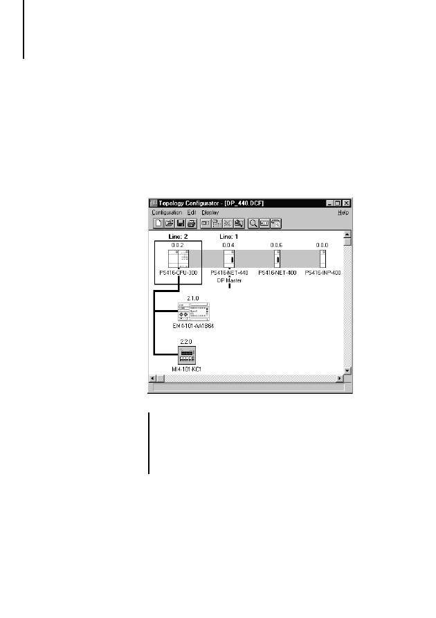
Master PS 416-NET-440 manages the PROFIBUS
line. The line number is assigned automatically in the
Sucosoft S 40 Topology Configurator.
In the Sucosoft S 40 Topology Configurator, enter
the slave’s station number, which is the same as the
Station Address in the CFG-DP configurator.
!
The address notation requires the listed module
number – “Module#x” – to be reduced by 1 each
time in the PROFIBUS-DP configurator.

Operation
30
09
/99
A
W
B
270
0-
1330
G
B
Moeller slave devices consisting of several modules
(e.g. an EM 4-204-DX1 with local expansion
modules), are addressed in the order in which they
are connected. The EM 4, for example, would have
module number 0 and the connected LE 4 module
numbers 1 to a maximum of 6 in ascending order.
Other makes of PROFIBUS-DP station are
addressed in accordance with the description in the
associated device master data (*.GSD) files. Consult
the device’s documentation for address details.
Example for PS 416-NET-440:
VAR
AnalogInput AT %IW2.3.1.0 : INT;
(* Analogue input word 0 of 1st LE of
3rd station in 2nd line *)
LimitValue: INT := 800 ;
END_VAR
LD
AnalogInput
GT
LimitValue
JMPC
Alarm
.
.
.
Alarm:
!
To address the input and output values of the
PROFIBUS-DP stations, master
PS 416-NET-440 must use address ID %I or %Q,
with a corresponding data width definition (X, B,
W or D). There are, for example, no special IDs for
analog values (%IAW, %QAW), which are
addressed using normal input and output
addresses.

Working principle of the
PS 416-NET-440/-441
31
09
/99
A
W
B
270
0-
1330
G
B
Example for PS 416-NET-441:
VAR
SetSpeed AT%SDW0.0.4.0:INT;
(*sends an integer value to the
master's receive data field*)
DefaultValue:INT:=800;
END_VAR
LD
DefaultValue
ST
SetSpeed
.
.
.
Working principle of the
PS 416-NET-440/-441
After the PLC is powered up, the PS 416-NET-440/-
441 performs a self-test. Any errors occurring during
the self-test are signalled by the LEDs on the front
panel (see Page 37).

32
09
/99
A
W
B
270
0-
1330
G
B

33
09
/99
A
W
B
270
0-
1330
G
B
6
Testing/Commissioning/Diagnostics
Commissioning the
PS 416-NET-440
For commissioning, the previously created
configuration must be transmitted to the
PS 416-CPU-x00. The procedure for configuring the
PS 416-NET-440 card is described in Chapter 4,
Page 19.
Requirements for downloading
To download a PROFIBUS-DP configuration to the
PS 416-NET-440,
the PS 416-CPU-x00 must be in status “ready”,
i.e. it must not be processing a program
and no program must be marked as active on the
PS 416-CPU-x00.
First, perform the following steps if the
PS 416-CPU-x00
is already processing a user program,
already contains a user program,
the existing configuration is to be changed,
the card has been replaced.
If no user program is loaded in the CPU, skip straight
to the Download section.
왘 In Sucosoft S 40, go to Test & Commissioning.
Testing/Commissioning/
Diagnostics
34
09
/99
A
W
B
270
0-
1330
G
B
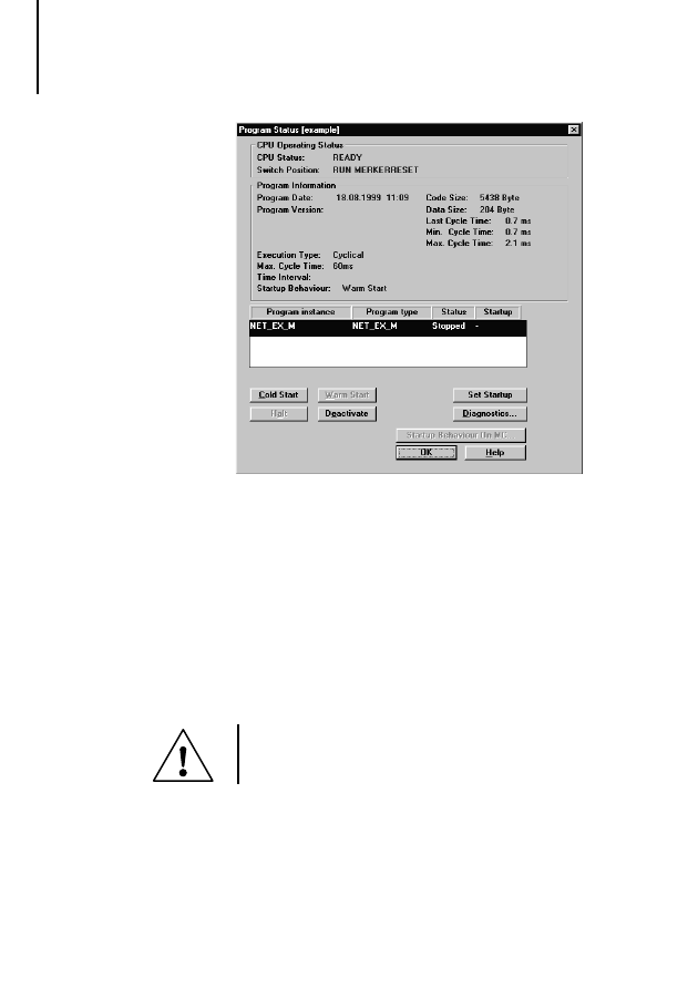
왘 Click the Halt button in the Program Status dialog
to stop the program.
왘 Click the Deactivate button to deactivate the user
program as the current process.
Downloading
왘 With the PROFIBUS-DP configurator CFG-DP,
transfer the firmware once to the card (for new
firmware versions only).
Caution!
Do not interrupt firmware transmission as this
prevents subsequent access to the cards.

Commissioning the
PS 416-NET-440
35
09
/99
A
W
B
270
0-
1330
G
B
왘 Then use the CFG-DP configurator to transfer the
PROFIBUS-DP configuration to the
PS 416-NET-440.
왘 In the Sucosoft S 40 topology configurator,
create the configuration for the PS 416 master
CPU in which the PS 416-NET-440 card is
installed.
When the program code is generated, this
configuration is linked with the PLC user program
and then sent to the master CPU with Sucosoft
S 40.
왘 In Test & Commissioning ➞ Program Status in
Sucosoft S 40, click the Cold Start button (see
Page 33). The PROFIBUS-DP configuration in the
PS 416-NET-440 will be compared with the
configuration data of the CPU.
During operation, diagnostic data from the
PS 416-NET-440 and the network slave can be
evaluated either using diagnostics bytes or the
function block “PdpStationDiag” in the PS 416 user
program (see Chapter 6, Page 41).
!
This comparison of the PROFIBUS-DP
configuration with the PLC program in the PS 416
CPU takes place only during the first cold start.

Testing/Commissioning/
Diagnostics
36
09
/99
A
W
B
270
0-
1330
G
B
PROFIBUS-DP communication
The PROFIBUS-DP communication depends on the
CPU’s operating status.
When the PS 416 CPU changes from “ready” to
“run”, data transfer via PROFIBUS-DP begins. The
“run” LED of the PS 416-NET-440 is lit continuously,
provided at least one station complying with the
desired configuration is connected.
When an error occurs and the status of the PS 416
CPU changes from “run” to “ready” or “not ready”,
data exchange via PROFIBUS-DP stops, and the
“run” LED on the PS 416-NET-440 flashes at regular
intervals.
Commissioning the
PS 416-NET-441
The following steps must be performed to
commission the PS 416-NET-441 card:
왘 In the Sucosoft S 40 topology configurator,
create the configuration for the PS 416 slave CPU
in which the PS 416-NET-441 card is installed.
When the program code is generated, this
configuration is linked with the PLC user program. It
must then be sent to the slave CPU with Sucosoft
S 40.
The procedure for configuring the PS 416-NET-441
card is described in Chapter 4, Page 22.

Status indication in the
operating phase
37
09
/99
A
W
B
270
0-
1330
G
B
Status indication in the
operating phase
The status of the PS 416-NET-440 and
PROFIBUS-DP communications is indicated by four
LEDs. The PS 416-NET-441 has three LEDs for this
purpose. They are located on the module’s front
panel.
!
During error-free data exchange with all
configured stations, all three LEDs of the
PS 416-NET-440 are lit. They are:
“run”, “ready” and “status”.
LED
Colour
Status
Meaning
PS 416-NET-440
run
green
on
Communication with at least one station in progress
cyclic flashing
Ready for communication
acyclic flashing
Parameter error
off
Communication interrupted
ready
yellow
on
PS 416-NET-440 ready for operation
cyclic flashing
Firmware must be transmitted or is being transmitted
(1 Hz or 2 Hz)
acyclic flashing
Hardware or firmware error
off
Hardware error
status
yellow
on
PS 416-NET-440 has the token, i.e., is the currently active
master of the network line
error
red
on
Transmission error during communication
PS 416-NET-441
bus
yellow
on
User data exchange with the PROFIBUS-DP master
flashing
No user data exchange. If the “config-error” LED also
flashes, the actual and set configuration do not correspond.
off
Startup phase
diag
red
on
A hardware error has occurred in the device.
The “config-error” LED is also lit.
off
Hardware OK
config error
red
on
Hardware fault in device. The “diag” LED is also lit.
flashing
Actual and set configuration do not correspond.
The “bus” LED also flashes.
off
Configuration OK
Testing/Commissioning/
Diagnostics
38
09
/99
A
W
B
270
0-
1330
G
B
Overview of diagnostic
bytes
Error messages from master CPU:
Comparison of data between PS 416-CPU and
PS 416-NET-440
Diagnostic byte from master PS 416-NET-440:
Information about master PS 416-NET-440;
group information from slaves
Diagnostic byte from slave PS 416-NET-441:
Byte0: information about status of slave
PS 416-NET-441; read by the slave CPU
Byte1: communication status of slave
PS 416-NET-441; read by the slave CPU
Extended byte1: information about slave CPU;
master CPU reads operating status of slave CPU
Extended byte2: service information about slave CPU
(e.g. state of backup battery)
General byte: indicator for extended diagnostic data
from slave; read by the master CPU
Function block “PdpStationDiag”:
Extended diagnostic message from slave; called by the
master CPU
CPU
POW
NET-440
CPU
POW
NET-441
PROFIBUS-DP
,,,
,,
,
Master PS 416
Slave PS 416

CPU error messages
39
09
/99
A
W
B
270
0-
1330
G
B
Diagnostic bytes indicate errors that have occurred
during testing, commissioning or operation. Their
physical location is
in master CPU PS 416 (
,
)
in master card PS 416-NET-440 (
)
in slave card PS 416-NET-441(
,
,
,
,
)
Diagnostic bytes are called, however, in the PLC user
program. The following bytes are used:
,
,
,
,
,
in the user program of master
CPU PS 416
,
in the user program of slave CPU PS 416
CPU error messages
Messages from the PS 416 CPU operating
system
During operation of the PS 416 with the
PS 416-NET-440 card, errors may arise during
transfer or cold start of the user program.
!
If, during the cold start of a user program, an I/O
error message appears, check the user
program’s I/O declarations in PROFIBUS-DP
operation against the S 40 configuration and
against the PROFIBUS-DP configuration.

Testing/Commissioning/
Diagnostics
40
09
/99
A
W
B
270
0-
1330
G
B
The following error codes are possible:
82C0
Error when reading the PROFIBUS-DP
configuration. (Indication during cold start)
82C2
The PS 416-NET-440 does not have a
PROFIBUS-DP configuration. (Indication
after transfer)
80FE
Error during parameter configuration of
PS 416-NET-440. (Indication after transfer
or during cold start; internal error)
82C3
Insufficient free memory for PROFIBUS-DP
configuration. (Indication during cold start)
82C4
There is no station with the specified
address in the PROFIBUS configuration.
(Indication after cold start)
82C5
More than 24 modules were configured for
one station. (Indication after cold start)
82C6
The operating system of the PS 416 CPU
does not know the configuration of the
PROFIBUS-DP line, because
the module is not inserted;
the assignment of line numbers to slot
numbers in the topology configuration is
not correct.

Diagnostic byte
of the master card
41
09
/99
A
W
B
270
0-
1330
G
B
Diagnostic byte
of the master card
PS 416-NET-440
The PS 416-NET-440 provides the user program
with a diagnostic byte, which is addressed with the
type “IS” input operator.
Assuming the PS 416-NET-440 is inserted in slot 6 of
the rack, then the diagnostic byte for this card is
declared as follows:
VAR
Status_440 AT %ISB0.0.6.0 : BYTE ;
END_VAR
The meaning of the bits of the diagnostic bytes is as
follows:
During error-free operation, all bits have the value “0”
(zero).
Bit 0:
reserved
Bit 1:
reserved
Bit 2:
reserved
Bit 3:
Group information; is set when a configured
station does not report on the bus. (“error”
LED of PS 416-NET-440 is lit)
Bit 4:
reserved
Bit 5:
is set when the PLC does not exchange data
with any station in operating status “run”.
Bit 6:
is set when the PS 416-NET-440 does not
have a valid configuration.
Bit 7:
is set when the self-test of the
PS 416-NET-440 was unsuccessful.

Testing/Commissioning/
Diagnostics
42
09
/99
A
W
B
270
0-
1330
G
B
Evaluation of the diagnostic byte in the user program
must consist of either:
evaluating the individual bits using the special
Moeller point notation
LD Status_440.3 (* Line station not reporting *)
or
checking the whole diagnostic byte for errors
LD
Status_440
NE
0
JMPC
Error
Diagnostic byte
of slave card
PS 416-NET-441
The PS 416-NET-441 provides the user program
with two diagnostic bytes, which are addressed with
the type “IS” input operator.
Assuming the PS 416-NET-441 is inserted in slot 5 of
the rack, then the diagnostic bytes for this card are
declared as follows:
VAR
Status1_441 AT %ISB0.0.5.0 : BYTE ;
Status2_441 AT %ISB0.0.5.1 : BYTE ;
END_VAR

Diagnostic byte
of slave card
43
09/99 AWB 2700-1330 GB
햴
BYTE 0
Bit 0:
The card is defective. Replace the card. The
signal is cleared automatically once the error
is rectified. A reset in the diagnostic status of
the CPU is not necessary.
Bit 1:
If a hardware fault has occurred; replace the
faulty card. The signal is cleared
automatically once the fault is rectified. A
reset in the diagnostic status of the CPU is
not necessary.
Bit 2:
If the input/output values are invalid, the card
performs an internal parameter configuration
shortly after power is restored or the
program is transferred. During this time, the
values that were read or written are invalid.
Permissible values can be read or output as
soon as the signal is cleared. The signal is
cleared automatically once the fault is
rectified.
A reset in the diagnostic status of
the CPU is not necessary.
Bit 3:
In case of a timeout, the communication
partners do not respond. This is either due to
a faulty card or a fault in the PROFIBUS-DP
line. Switch the system off and on again and
observe the notes about cable routing in the
manuals. The signal is cleared automatically
once the fault is rectified. A reset of the
diagnostic status of the CPU is not
necessary.

Testing/Commissioning/
Diagnostics
44
09
/99
A
W
B
270
0-
1330
G
B
BYTE 1
Bit 2:
A configuration error indicates that the local
configuration does not match the sent
PROFIBUS-DP configuration of the master.
Check the configured send and receive data
lengths in the Sucosoft S 40 topology
configuration and the PROFIBUS-DP
configuration of the master. The signal is
cleared automatically once the fault is
rectified. A reset in the diagnostic status of
the CPU is not necessary.
Bit 3:
If “SYNC” is active, the station’s receive data
(the output data for the PROFIBUS-DP
master) has been frozen with a “SYNC”
command from the master. The message
disappears automatically when an
“UNSYNC” command is received.
Bit 4:
If “FREEZE” is active, the card’s send data
(the input data for the PROFIBUS-DP
master) has been frozen with a “FREEZE”
command from the master. The message
disappears automatically when an
“UNFREEZE” command is received.
!
For a description of the “PdpFreezeSync”
function block, see manual AWB 2700-1306
“Language Elements for PS 4-150/-200/-300 and
PS 416”.

Diagnostic byte
of slave card
45
09
/99
A
W
B
270
0-
1330
G
B
Bit 6:
If no PROFIBUS-DP communication is
taking place, the master of the
PROFIBUS-DP line does not exchange user
data with the station. Check:
the master’s power supply
that the master is in the correct operating
mode for communication
for an interrupted connection
that the PROFIBUS-DP address is
correct
that the station has been configured in
the PROFIBUS-DP configurator
that the data length in the PROFIBUS-DP
configurator corresponds with the locally
configured data lengths. If the
configuration data is not the same, bit 2 –
“config-error” – will be set.
The signal is cleared automatically once the
fault is rectified.
A reset in the diagnostic
status of the CPU is not necessary.

Testing/Commissioning/
Diagnostics
46
09
/99
A
W
B
270
0-
1330
G
B
Card PS 416-NET-441 provides extended, station-
specific information to the respective PROFIBUS-DP
master in the line. On PROFIBUS-DP masters
PS 416-NET-440 and LE 4-504-BS1 from Moeller,
this extended information is scanned with the help of
function block “PdpStationDiag”. For details about
scanning extended diagnostic data with other
PROFIBUS-DP masters, refer to the manufacturer’s
documentation.
The extended diagnostic information is stored in two
bytes, whose significance is also described in the
GSD file:
First byte of the extended diagnosis
Bit 0:
The PLC is in status “not ready”. The PS 416
PLC with card PS 416-NET-441 has a fatal
error or does not have an operating system.
Load an operating system or replace the
CPU.
Bit 1:
The PLC is in Halt mode. The PS 416 PLC
has stopped.
Bit 2:
If the message “Diag” appears, one or more
diagnostic messages are pending on the
PS 416 PLC. In Sucosoft S 40, call up the
diagnostic messages with “Test &
Commissioning” and check the extended
information in the second byte.

Diagnostic byte
of slave card
47
09
/99
A
W
B
270
0-
1330
G
B
Second byte of extended diagnosis (message
bits of host CPU)
Slave stations – general
Each slave in the PROFIBUS-DP has a diagnostic
byte that can be addressed with the type “IS” input
operator by the user program of master CPU PS 416.
The line number and station number are defined by
the configuration; the card number is always “0”.
Bit 0:
If the message “DAK” appears, there is an
error in the local configuration. The topology
configuration for the slave CPU does not
correspond with the actual configuration. If
no card is recognized in the slot, the card did
not respond when it was addressed, or a
nonexistent card was addressed.
Bit 1:
If the message “DDK” appears, there is an
error in the remote configuration.
The
topology configuration of one or more
network lines connected to the slave CPU
does not correspond with the actual
configuration. In Test & Commissioning in
the Sucosoft S 40 Topology Configurator,
use the network diagnostics to check which
lines and stations are affected.
Bit 2:
The message “DBM” (battery monitor),
indicates that the backup battery is empty
and must be replaced. It is located at the
front of the PS 416 CPU or in the PCMCIA
SRAM memory card of the CPU.

Testing/Commissioning/
Diagnostics
48
09
/99
A
W
B
270
0-
1330
G
B
Example:
The diagnostic byte of the tenth station on network
line 2 is assigned by the variable declaration.
VAR
Status_Slave AT %ISB 2.10.0.0 : BYTE ;
END_VAR
Bits 4 and 6 are important for diagnosis. They can be
declared and evaluated as Boolean variables.
VAR
Bit4_Slave10 AT %IS2.10.0.0.4 : BOOL ;
Bit6_Slave10 AT %IS2.10.0.0.6 : BOOL ;
END_VAR
In the former case, only those bits relevant to the
diagnostic byte must be filtered out before evaluation
(in the example these are bits 4 and 6):
LD
2#01010000
AND
Status_Slave
ST
Cleared
The two relevant bits have the following meaning:
Bit 4:
Diagnostic bit.
Extended diagnostic data for the station is
available. This data can be read in the user
program with function block
“PdpStationDiag”. This bit is reset to “0”
after its evaluation by the function block.
Bit 6:
Communication bit.
This is set when there is an error in the data
exchange with the station, for example when
the station is not connected or is incorrectly
configured.
Function block
“PdpStationDiag”
49
09
/99
A
W
B
270
0-
1330
G
B
Function block
“PdpStationDiag”
Extended diagnostic messages from slaves
Requesting diagnostic data from PROFIBUS-DP
station
Prototype of the function block
Meaning of operands
PdpStationDiag
ARRAY[1..100] OF BYTE
Diagnostics
Diagnostics
BOOL
Strobe
Active
BOOL
USINT
MasterSlot
State1
BYTE
USINT
StationAddress
State2
BYTE
State3
BYTE
MasterAddress
USINT
Ident
UINT
error
UINT
Name
Meaning
Diagnostics
Transfers an array of 100 bytes. The station’s extended diagnostic data is stored here
Strobe
Enables the function block; the diagnostic job is initiated
MasterSlot
Slot number of associated PS 416-NET-440 card
Value range: 4 to 19; decimal
StationAddress
Address of the PROFIBUS-DP slave whose diagnostic data is to be read
Active
Display of job processing status
1: job accepted; 1 to 0: job finished
State 1
Standard diagnostic byte 1 of PROFIBUS-DP
State 2
Standard diagnostic byte 2 of PROFIBUS-DP
State 3
Standard diagnostic byte 3 of PROFIBUS-DP
MasterAddress
Provides address of master module to which addressed slave is assigned
Ident
Provides specific ID of PROFIBUS-DP station
Error
Error messages

Testing/Commissioning/
Diagnostics
50
09
/99
A
W
B
270
0-
1330
G
B
Description
Function block “PdpStationDiag” can be used to
scan the standard and extended diagnostic data (if
available) of the PROFIBUS-DP slave. The scan is
performed with a rising edge at the Strobe input of
the function block. The address parameters
(StationAddress, MasterAddress, MasterSlot, Ident)
are used to define the slave whose diagnostic data is
to be read.
If output Active is “1”, the job was accepted after an
input value validity check. As long as this output
stays “1”, the status of input Strobe is ignored. If
output Active changes from “1” to “0” and output
Error is “0”, then the job was processed successfully.
If, however, output Error has a value other than zero,
an error has occurred. The error can be identified by
means of the value at output Error.
The value of output Error has the following meaning:
!
Function block “PdpStationDiag” must be
instantiated only once for each PS 416-NET-440
in the user program.
0
No error
1
Defective function block;
defective function block library
2
Diagnostic data cannot be requested
3
Error when receiving diagnostic data
4
Invalid slot number
Permissible range: 4 to 19
5
Invalid station number
Permissible range: 1 to 125

Function block
“PdpStationDiag”
51
09
/99
A
W
B
270
0-
1330
G
B
The Diagnosis parameter specifies a 100-element
array of type BYTE. The extended diagnostic data of
the addressed slave is entered here.
If the job is carried out successfully, then the
PS 416-NET-440 always returns 100 bytes,
regardless of the actual length of the diagnostic data.
7
The topology configuration does not specify a
card for the specified slot
8
The PS 416-NET-440 is not specified for the
specified slot
9
The PS 416-NET-440 is not ready for
operation
10
The PROFIBUS-DP configuration does not
contain the specified station
11
No diagnostic data is available for the
specified station
15
The slot is already occupied by another
function block (blocks PdpStationDiag or
PdpFreezeSync were not called sequentially,
and at least one of these blocks is still active)
!
Make sure that the array sent at the Diagnosis
input/output is 100 bytes long!
Testing/Commissioning/
Diagnostics
52
09
/99
A
W
B
270
0-
1330
G
B
When the job is completed successfully, the function
block returns three diagnostic bytes from the
PROFIBUS-DP.
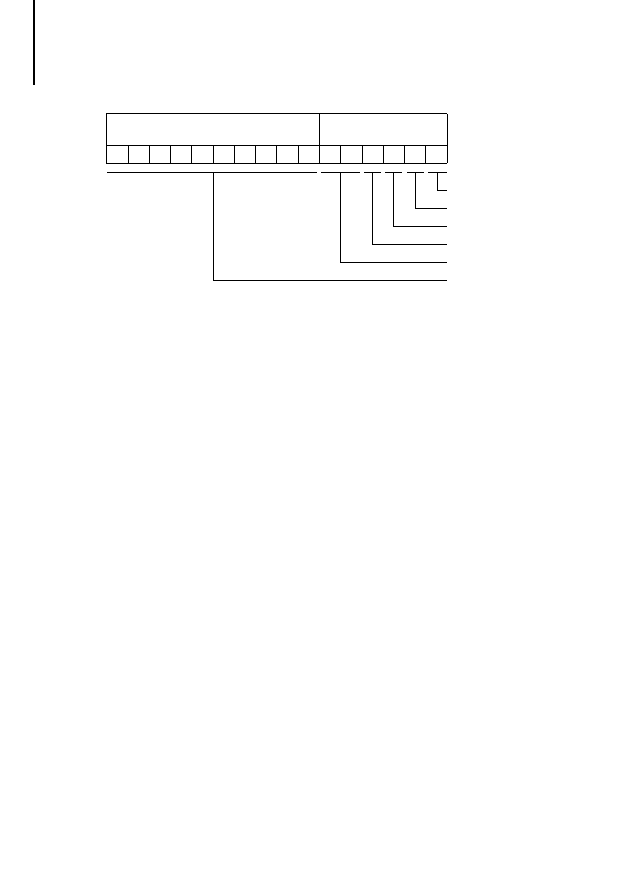
Extended diagnostics/device-specific
Standard slave
diagnostics
15 14 13 12 11 10
9
8
7
6
5
4
3
2
1
0
State 1
State 2
State 3
MasterAddress
Ident
Diagnostics
State1
Bit 0:
No response from station
Bit 1:
Station not ready for data transfer
Bit 2:
Station parameters incorrectly configured
Bit 3:
Station-specific diagnostic data is available
Bit 4:
Station has detected an unknown
command.
Bit 5:
Implausible response from station
Bit 6:
Incorrect parameter settings (e.g. ID number)
Bit 7:
Station parameters were configured by
another master
State2
Bit 0:
Station parameters not configured
Bit 1:
Static diagnosis
Bit 2:
Permanently set to 1
Bit 3:
Response monitoring active
Bit 4:
Freeze command active
Bit 5:
Sync command active
Function block example
53
09
/99
A
W
B
270
0-
1330
G
B
Function block
example
Slot 7 of a PS 416 rack contains a PS 416-NET-440
card, which manages the PROFIBUS-DP line with
two slave stations:
one CM 4-504-GS1 (gateway)
one EM 4-204-DX1 with local expansion modules
Initially, the topology configuration is created in the
Sucosoft S 40 Topology Configurator. The
procedure configurating topologies is described in
manual AWB 2700-1305 GB “Sucosoft S 40 User
Interface”.
Bit 6:
Reserved
Bit 7:
PROFIBUS-DP configuration does not
contain the specified station
State3
Bit 0 to bit 6: reserved
Bit 7:
Extended station diagnostic data longer than
100 bytes
Testing/Commissioning/
Diagnostics
54
09
/99
A
W
B
270
0-
1330
G
B
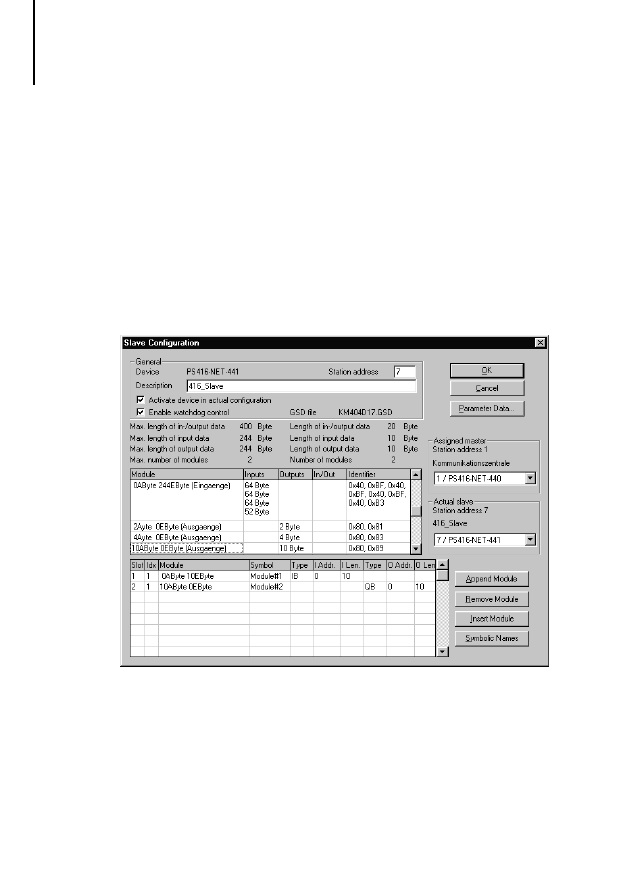
The two slave stations are added and parameterized
in the PROFIBUS-DP configurator CFG-DP. For
details about operating the CFG-DP configurator,
refer to the electronic manual
AWB EM 2700-1336 GB (PDF file for Acrobat
Reader), which is included with the Sucosoft S 40
software.
To set the parameters of slave CM 4-504-GS1 with
station address 10, 16 bytes will be transferred in
each direction in this example.
Function block example
55
09
/99
A
W
B
270
0-
1330
G
B
In the example, EM 4-204-DX1 with station address
4 has a total of six local expansions, including an
LE 4-206-AA1 analog module in the first position.
Testing/Commissioning/
Diagnostics
56
09
/99
A
W
B
270
0-
1330
G
B
This configuration is stored and sent to the
PS 416-NET-440 card.
The sample program listed below uses the topology
configuration created with Sucosoft S 40 to generate
an executable program for the PS 416. The
configuration is then transferred to the PS 416 CPU.
As well as carrying out an error analysis, you should
implement the following program sequences when
working with the function block.

Function block example
57
09
/99
A
W
B
270
0-
1330
G
B
The functions of the individual program sections are
listed below and are labelled with a corresponding
comment at the start of each section:
Registering all set diagnostic bits
Calling the function block for all registered
diagnostic bits
Entering the diagnostic data in a station-specific
buffer
Enabling the function block for a restart
Evaluating the diagnostic data
If diagnostic messages occur frequently and from
several stations at the same time, you should assign
priority to the function block call. This ensures that all
diagnostic data from the most important stations is
received.
The following example suggests a solution for the
function block whenever two stations send a
diagnosis at the same time. The solution guarantees
that each diagnostic message will be evaluated, even
if one of the stations continually sets the diagnostic
bit.
!
The master card always contains only the last
diagnostic message of a station. The diagnostic
bit remains set until the diagnostic data is fetched
by a function block call.

Testing/Commissioning/
Diagnostics
58
09
/99
A
W
B
270
0-
1330
G
B
Program DP_Diagnostics
VAR
(* Status DP line, master in slot 7 *)
DP_Status_Line_1
AT %ISB0.0.7.0 :
BYTE;
(* DP---Line 1---Station 4---Module 0---EM4-204-DX1--- *)
(* Status byte, station 4 *)
Status_EM_4_204_ADR_4
AT %ISB1.4.0.0 :
BYTE;
em4204DX1_Modul0_IB0
AT %IB1.4.0.0 :
BYTE;
em4204DX1_Modul0_IB1
AT %IB1.4.0.1 :
BYTE;
le4206AA1_Modul1_IW0
AT %IW1.4.1.0 :
UINT;
le4206AA1_Modul1_IW2
AT %IW1.4.1.2 :
UINT;
le4206AA1_Modul1_IW4
AT %IW1.4.1.4 :
UINT;
le4206AA1_Modul1_IW6
AT %IW1.4.1.6 :
UINT;
le4206AA1_Modul1_QW0
AT %QW1.4.1.0 :
UINT;
le4206AA1_Modul1_QW2
AT %QW1.4.1.2 :
UINT;
le4116XD1_Modul2_QB0
AT %QB1.4.2.0 :
BYTE;
le4116XD1_Modul2_QB1
AT %QB1.4.2.1 :
BYTE;
le4116XD1_Modul3_QB0
AT %QB1.4.3.0 :
BYTE;
le4116XD1_Modul3_QB1
AT %QB1.4.3.1 :
BYTE;
le4116DX1_Modul4_IB0
AT %IB1.4.4.0 :
BYTE;
le4116DX1_Modul4_IB1
AT %IB1.4.4.1 :
BYTE;
le4308HX1_Modul5_IB0
AT %IB1.4.5.0 :
BYTE;
le4308XH1_Modul6_QB0
AT %QB1.4.6.0 :
BYTE;
(* DP---Line 1------Station 10--- GateWay--CM4-504-GS1--------- *)
(* Status byte, station 10 *)
Status_GateWay_ADR_10
AT %ISB1.10.0.0:
BYTE;
cm4504_IB0
AT %IB1.10.0.0 :
BYTE;
(* max. 16 bytes: 0 - 15 *)
cm4504_IB15
AT %IB1.10.0.15:
BYTE;
cm4504_QB0
AT %QB1.10.0.0 :
BYTE;
(* max 16 bytes: 0 - 15 *)
cm4504_QB15
AT %QB1.10.0.15:
BYTE;

Function block example
59
09
/99
A
W
B
270
0-
1330
G
B
(***********************************************************************************)
(*
Diagnosis of all line stations *)
(***********************************************************************************)
FB_DP_Diag
:
PDPSTATIONDIAG;
Strobe
:
BOOL;
FB_DP_Diag_F_Edge
:
F_TRIG;
DP_Diag
:
ARRAY[1..100] OF BYTE;
DP_Address
:
USINT;
DP_MASTERSLOT :
USINT;
GateWay_ADR_10_Diag
:
ARRAY[1..100] OF BYTE;
Buffer_Adr4
:
ARRAY[1..13] OF BYTE;
Buffer_Adr10
:
ARRAY[1..6] OF BYTE;
ADR4_Diag_Flag
:
BOOL;
ADR10_Diag_Flag
:
BOOL;
DiagCounter
:
USINT;
TestDiagBit_ADR4
:
FB_DiagBitCounter;
TestDiagBit_ADR10
:
FB_DiagBitCounter;
END_VAR
LD
DP_Status_Line_1(* Status byte DP *)
(* Evaluate DP line status byte *)
(*...*)
(* Status byte for DP station
*)
LD
Status_EM_4_204_ADR_4.6
(* Communication bit for station 4 *)
LD
Status_GateWay_ADR_10.6
(* Communication bit for station 10 *)
(* Evaluate communication bit *)
(*...*)
(** Begin ******************* Evaluate diagnosis ***********************************)
(***********************************************************************************)
(*
Register all set diagnostic bits
*)
(***********************************************************************************)
(* Diagnostic bit counter Addr.4 *)
CAL TestDiagBit_ADR4(
enable :=1,
InBit :=Status_EM_4_204_ADR_4.4
|
:=SetDiagBitCounter)
(* Diagnostic bit counter Addr.10 *)

Testing/Commissioning/
Diagnostics
60
09
/99
A
W
B
270
0-
1330
G
B
CAL TestDiagBit_ADR10(
enable :=1,
InBit :=Status_GateWay_ADR_10.4
|
:=SetDiagBitCounter)
(* Diagnostic detected then set diagnostic flags *)
LD
FB_DP_Diag.Active
EQ
1
JMPC
_DiagCall
(* Diagnostic request still active *)
LD
DiagCounter
(* Counter of detected diagnostic events *)
EQ
0
(* All diagnostics requests have been sent*)
JMPC
_ADR4
(* Entry of new diagnostic flags possible *)
JMP
_DiagSelect
(* Continue processing diagnostic flags *)
_ADR4:
(* Set diagnostic flag if ADR 4 reports diagnostic*)
LD
Status_EM_4_204_ADR_4.4
JMPCN
_ADR10
LD
DiagCounter
ADD
1
ST
DiagCounter
(* Increment diagnostic counter *)
LD
1
ST
ADR4_Diag_Flag
(* Set diagnostic flag for addr. 4*)
_ADR10:
(* (* Set diagnostic flag if ADR 10 reports diagnostic**)
LD
Status_GateWay_ADR_10.4
JMPCN
_ADRx
LD
DiagCounter
ADD
1
ST
DiagCounter
LD
1
ST
ADR10_Diag_Flag
(* (* Set diagnostic flag for addr. 10 **)
_ADRx:
(*...*)

Function block example
61
09
/99
A
W
B
270
0-
1330
G
B
(***********************************************************************************)
(*
Function block call for all registered diagnostic bits*)
(***********************************************************************************)
_DiagSelect:
(* Process set diagnostic flags *)
LD
ADR4_Diag_Flag
JMPC
_prepareDiag_ADR4
LD
ADR10_Diag_Flag
JMPC
_prepareDiag_ADR10
JMP
_DiagCall
(* No diagnostic bit set *)
_prepareDiag_ADR4:
(* Enter parameters for diagnostics function block *)
LD
Status_EM_4_204_ADR_4.4
ST
FB_DP_Diag.Strobe
LD
4
ST
DP_Address
LD
7
ST
DP_MASTERSLOT
LD
0
ST
ADR4_Diag_Flag
JMP
_DiagCounter
_prepareDiag_ADR10:
LD
Status_GateWay_ADR_10.4
ST
FB_DP_Diag.Strobe
LD
10
ST
DP_Address
LD
7
ST
DP_MASTERSLOT
LD
0
ST
ADR10_Diag_Flag
JMP
_DiagCounter
_DiagCounter:(* Decrement diagnosis counter *)
LD
DiagCounter
SUB
1
ST
DiagCounter

Testing/Commissioning/
Diagnostics
62
09
/99
A
W
B
270
0-
1330
G
B
(***********************************************************************************)
(*
Function block call
*)
(***********************************************************************************)
_DiagCall:
CAL FB_DP_Diag(
STROBE :=,
MASTERSLOT :=DP_MASTERSLOT,
STATIONADDRESS :=DP_Address,
DIAGNOSE :=DP_Diag
|
:=ACTIVE,
:=STATE1,
:=STATE2,
:=STATE3,
:=MASTERADDRESS,
:=IDENT,
:=ERROR)
(* Evaluate falling edge of Active output *)
CAL FB_DP_Diag_F_Edge(
CLK :=FB_DP_Diag.Active
|
:=Q)
LD
FB_DP_Diag_F_Edge.Q
JMPCN
_DiagEnd
(* Falling edge detected *)
LD
FB_DP_Diag.Error
(* FB error detection *)
EQ
0
JMPC
_NoError
(* error-free *)
(*...*)
JMP
_DiagStrobe0
_NoError:
(* Enter diagnostic data in station diagnostics buffer *)
LD
DP_Address
EQ
4
JMPC
_DiagData_ADR4
LD
DP_Address
EQ
10
JMPC
_DiagData_ADR10
JMP
_DiagStrobe0

Function block example
63
09
/99
A
W
B
270
0-
1330
G
B
(***********************************************************************************)
(*
Enter diagnostic data in station-specific buffer*)
(***********************************************************************************)
_DiagData_ADR4:
(* Verify Master address and ID No. *)
LD
FB_DP_Diag.Masteraddress
LD
FB_DP_Diag.Ident
(*...*)
(* Enter diagnosis data in buffer *)
LD
FB_DP_Diag.STATE1
ST
Buffer_Adr4[1]
LD
FB_DP_Diag.STATE2
ST
Buffer_Adr4[2]
LD
FB_DP_Diag.STATE3
ST
Buffer_Adr4[3]
LD
DP_Diag[1]
ST
Buffer_Adr4[4]
LD
DP_Diag[2]
ST
Buffer_Adr4[5]
LD
DP_Diag[3]
ST
Buffer_Adr4[6]
LD
DP_Diag[4]
ST
Buffer_Adr4[7]
LD
DP_Diag[5]
ST
Buffer_Adr4[8]
LD
DP_Diag[6]
ST
Buffer_Adr4[9]
LD
DP_Diag[7]
ST
Buffer_Adr4[10]
LD
DP_Diag[8]
ST
Buffer_Adr4[11]
LD
DP_Diag[9]
ST
Buffer_Adr4[12]
LD
TestDiagBit_ADR4.SetDiagBitCounter
ST
Buffer_Adr4[13]
JMP
_DiagStrobe0

Testing/Commissioning/
Diagnostics
64
09
/99
A
W
B
270
0-
1330
G
B
_DiagData_ADR10:
(* Verify Master address and ID No. *)
LD
FB_DP_Diag.Masteraddress
LD
FB_DP_Diag.Ident
(*...*)
(* Enter diagnosis data in buffer *)
LD
FB_DP_Diag.STATE1
ST
Buffer_Adr10[1]
LD
FB_DP_Diag.STATE2
ST
Buffer_Adr10[2]
LD
FB_DP_Diag.STATE3
ST
Buffer_Adr10[3]
LD
DP_Diag[1]
ST
Buffer_Adr10[4]
LD
DP_Diag[2]
ST
Buffer_Adr10[5]
LD
TestDiagBit_ADR10.SetDiagBitCounter
ST
Buffer_Adr10[6]
JMP
_DiagStrobe0
(***********************************************************************************)
(*
Enable function block for a restart
*)
(***********************************************************************************)
_DiagStrobe0:
(* Output Strobe 0 after falling edge *)
CAL FB_DP_Diag(
STROBE :=0,
MASTERSLOT :=,
STATIONADDRESS :=,
DIAGNOSE :=DP_Diag)
_DiagEnd:
(***********************************************************************************)
(*
Evaluate diagnostic data
*)
(***********************************************************************************)
(*...*)
(** End ******************* Evaluate diagnostic data ********************************)

Function block example
65
09
/99
A
W
B
270
0-
1330
G
B
(***********************************************************************************)
(*
I-O Addressing of DP Stations
*)
(***********************************************************************************)
LD
16#FF
ST
le4116XD1_Modul2_QB1
(*...*)
_END:
END_PROGRAM
FUNCTION_BLOCK FB_DiagBitCounter
VAR_OUTPUT
SetDiagBitCounter:BYTE;
END_VAR
VAR_INPUT
enable
:
BOOL;
InBit
:
BOOL;
END_VAR
VAR
Set_Edge
:
R_TRIG;
END_VAR
LD
enable
JMPCN _End
(* Evaluate if bit was set *)
CAL Set_Edge(
CLK :=InBit
|
:=Q)
LD
Set_Edge.Q
EQ
1
JMPC
_SetBit
JMP
_End
(* Count occurrences of DiagBit *)
_SetBit:
LD
SetDiagBitCounter
BYTE_TO_USINT
ADD
1
USINT_TO_BYTE
ST
SetDiagBitCounter
_END:
END_FUNCTION_BLOCK

66
09
/99
A
W
B
270
0-
1330
G
B

67
09
/99
A
W
B
270
0-
1330
G
B
Appendix
Technical data
Current consumption
max. 0.8 A (PS 416-NET-440);
0.5 A (PS 416-NET-441)
Ambient temperature
(0 to 55) °C
Storage temperature
(–20 to 70) °C
Isolation voltage
850 V DC
Vibration resistance
1 g/(0 to 150) Hz
Shock resistance
15 g/11 ms
Degree of protection
IP 20
Weight
210 g (PS 416-NET-440);
130 g (PS 416-NET-441)
Interface
PROFIBUS-DP (EN 50 170, Vol.
Station type
PS 416-NET-440: master (class 1)
PS 416-NET-441: slave
Electrical standard
RS 485
Electrical isolation
Yes
Baud rate detection
automatic
Baud rate [kbit/s]
Cable lengths [m]
9.6
1200
19.2
1200
93.75
1200
187.5
1000
500
400
1500
200
3000
100
6000
100
12000
100
Cable
ZB 4-900-KB1;
specifically for PROFIBUS-DP
Connector
ZB 4-209-DS2; special PROFIBUS-DP
connector up to 12 Mbit/s with switchable
bus terminating resistors

68
09
/99
A
W
B
270
0-
1330
G
B

69
09
/99
A
W
B
270
0-
1330
G
B
Index
A
Active .............................................................................. 50
Address notation............................................................. 27
Addressing
PROFIBUS-DP cards .................................................. 27
PROFIBUS-DP stations............................................... 29
B
Bus terminating resistor .................................................. 14
C
Cabling ...................................................................... 11
,
Cards
Fitting and removing.................................................... 17
Commissioning
PS 416-NET-440 ......................................................... 33
PS 416-NET-441 ......................................................... 36
Configuring
PS 416-NET-440 ......................................................... 19
PS 416-NET-441 ......................................................... 22
Connecting
Cards ........................................................................... 13
PC to PS 416-NET-440 ............................................... 16
Stations ....................................................................... 14
Connection assignment
PROFIBUS-DP ............................................................ 12
D
Data plug......................................................................... 14
Diagnostics
Extended diagnostic bytes.......................................... 46
Function block PdpStationDiag .................................. 50
Operating system ........................................................ 39
PS 416-NET-440 ......................................................... 41
PS 416-NET-441 ......................................................... 42
Downloading ................................................................... 34
Requirements .............................................................. 33

Index
70
09
/99
A
W
B
270
0-
1330
G
B
E
Error messages from CPU .............................................. 39
Errors ............................................................................... 50
Extended diagnostic bytes.............................................. 46
F
Function block PdpStationDiag
Description................................................................... 50
Diagnostic data............................................................ 49
Example ....................................................................... 54
Operands and their meaning ....................................... 50
Program DP_Diagnostics............................................. 59
H
Hardware requirements..................................................... 6
I
Ident ................................................................................ 50
Interface
CFG..........................................................................8
,
PROFIBUS-DP.................................................. 8
,
L
LEDs ............................................................................8
,
M
MasterAddress ................................................................ 50
MasterSlot ....................................................................... 50
Mirror mode..................................................................... 27
N
Number
O
Overview of diagnostic bytes .......................................... 38

Index
71
09
/99
A
W
B
270
0-
1330
G
B
P
Pin assignment
CFG interface .............................................................. 12
Power supply .................................................................. 16
PROFIBUS-DP communication ...................................... 36
Programming cable......................................................... 12
Protective cap ................................................................... 8
Purpose of the card .......................................................... 5
R
Requirements
Downloading ............................................................... 33
Hardware ....................................................................... 6
Software ........................................................................ 6
S
Screening ........................................................................ 11
Setup
PS 416-NET-440 ........................................................... 7
PS 416-NET-441 ........................................................... 9
Software requirements...................................................... 6
State 1............................................................................. 50
State 2............................................................................. 50
State 3............................................................................. 50
StationAddress ............................................................... 50
Status LEDs .................................................................... 37
Strobe ............................................................................. 50
T
Topology Configurator .................................................... 19
W
Wiring .............................................................................. 13
Working principle of the PS 416-NET-440...................... 31

72
09
/99
A
W
B
270
0-
1330
G
B
Document Outline
- Titel
- Before commencing the installation
- Contents
- About This Manual
- 1 About the Cards
- 2 Configuration
- 3 Installation
- 4 Software Configuration
- 5 Operation
- 6 Testing/Commissioning/Diagnostics
- Appendix
- Index
Wyszukiwarka
Podobne podstrony:
PS4 PS 416 TCS 200 h1298g Telecontrol Card
PS4 PS 4 271 MM1 h1364g
h1239g PLC PS4 416
Mastering Visual Basic NET Database Programming
h1239g PLC PS4 416
PS4 LE 4 504 BS1, Master h1368g
Sybex Mastering Visual Basic NET VB NET Functions (VBL)
h1244g MODBUS PLC PS4 416
440 PS AT
PS VI
PS spolecznosc lokalna 3
Safety net
PS 1 Psychologia społeczna wstep
PS Organiz 11
PS Komunikacja 910
więcej podobnych podstron