
Hardware and Engineering
PS 416-TCS-200
Telecontrol Card
08/97 AWB 27-1298 GB
1st published 1997, edition 08/97
© Moeller GmbH, Bonn
Author:
Thomas Dahmen
Editors:
Klaus Krüger, Thomas Kracht
Translators: Christopher Baker, Terence Osborn
1298u1g.fm Seite 1 Dienstag, 23. Februar 1999 12:54 12

Caution!
Dangerous electrical voltage!
Before commencing the installation
●
Disconnect the power supply of the
device.
●
Ensure that the device cannot be
accidentally restarted.
●
Verify isolation from the supply.
●
Earth and short circuit.
●
Cover or enclose neighbouring units that
are live.
●
Follow the engineering instructions
(AWA) of the device concerned.
●
Only suitably qualified personnel may
work on this device/system.
●
Before installation and before touching
the device ensure that you are free of
electrostatic charge.
●
Connecting cables and signal lines
should be installed so that inductive or
capacitive interference do not impair the
automation functions.
●
Install automation devices and related
operating elements in such a way that
they are well protected against
unintentional operation.
●
Suitable safety hardware and software
measures should be implemented for
the I/O interface so that a line or wire
breakage on the signal side does not
result in undefined states in the
automation devices.
●
Ensure a reliable electrical isolation of
the low voltage for the 24 volt supply.
Only use power supply units complying
with IEC 60 364-4-41 or HD 384.4.41 S2.
●
Deviations of the mains voltage from the
rated value must not exceed the
tolerance limits given in the
specifications, otherwise this may cause
malfunction and dangerous operation.
●
Emergency stop devices complying with
IEC/EN 60 204-1 must be effective in all
operating modes of the automation
devices. Unlatching the emergency-stop
devices must not cause uncontrolled
operation or restart.
●
Devices that are designed for mounting
in housings or control cabinets must only
be operated and controlled after they
have been installed with the housing
closed. Desktop or portable units must
only be operated and controlled in
enclosed housings.
●
Measures should be taken to ensure the
proper restart of programs interrupted
after a voltage dip or failure. This should
not cause dangerous operating states
even for a short time. If necessary,
emergency-stop devices should be
implemented.
IBM is a registered trademark of International
Business Machines Corporation.
All other brand and product names are
trademarks or registered trademarks of the
owner concerned.
All rights reserved, including those of the
translation.
No part of this manual may be reproduced in
any form (printed, photocopy, microfilm or
any otherprocess) or processed, duplicated
or distributed by means of electronic
systems without written permission of
Moeller GmbH, Bonn.
Subject to alterations without notice.

1
0
8
/97
AW
B
27
-1
29
8-
GB
Contents
Setting Up A Telecontrol Station With
The PS 416 Controller
Hardware and software requirements
Construction of the PS 416-TCS-200
Number of PS 416-TCS-200 cards in
the rack
Installing the PS 416-TCS-200 in the rack

2
0
8
/97
AW
B
27
-1
29
8-
GB

3
0
8
/97
AW
B
27
-1
29
8-
GB
About This Manual
This card has been developed for remote metering,
remote indication and remote control and supports
the data security protocols FT 1.2 and FT 3
(asynchronous) as per the IEC 870-5 standard for
telecontrol equipment and systems.
This manual describes the structure, planning,
configuration, installation, operation and also the
testing and diagnostics of the PS 416-TCS-200
communication processor. The PS 416-TCS-200 is a
communication processor for PS 416 programmable
logic controller. With the aid of the PS 416-TCS-200
communication processor the PS 416 can be
connected as telecontrol station to a telecontrol
network.
This documentation is intended for the project
planner, programmer and commissioning engineer.
This documentation will enable such users to
connect the PS 416 to a telecontrol system.
A general knowledge of control and communication
engineering is required for a good comprehension of
this technical documentation.
Other manuals (AWBs)
The fundamentals of remote control using compact
PLCs are described in a separate manual. Each of
the individual components also has its own manual.
Guide to telecontrol, AWB 27-1299-GB
ZB 4-501-TC1:
Hardware and engineering, telecontrol card
ZB 4-501-TC1, AWB 27-1297-GB

About This Manual
4
0
8
/97
AW
B
27
-1
29
8-
GB
PS 416-TCS-200:
Hardware and engineering, telecontrol card PS 416-
TCS-200, AWB 27-1298-GB
Leased line S 40-AM-TL:
Telecontrol via leased line, application module S 40-
AM-TL, AWB 27-1301-GB
Dial-up line S 40-AM-TD:
Telecontrol via dial-up line, application module
S 40-AM-TD, AWB 27-1300-GB
5
0
8
/97
AW
B
27
-1
29
8-
GB
1
Setting Up A Telecontrol Station With
The PS 416 Controller
The PS 416-TCS-200 communication processor
forms part of the PS 416 modular control system.
With the PS 416-TCS-200 the individual controller
can be integrated into a telecontrol system. Here the
controller can be the central station or a substation.
Communication with the telecontrol network is
effected via modem and modem cable.
Communication is supported by task-specific
application modules (function blocks).
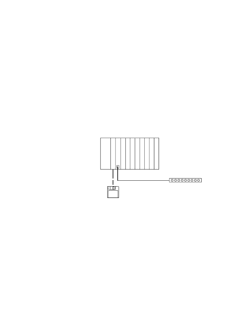
Figure 1: Layout of a telecontrol station with the PS 416
programmable controller
a Central station
b Modem
Either a dial-up line or a leased line can be used as the
transmission medium.
In the case of the dial-up line existing telephone
networks are used as transmission medium. All of the
modems in the central station and substations must
be modems with dialling capability. At the request of
S 40-AM-TD/TL
ZB 4-254-KB1
b
CPU PS 416
PS 416-TCS-200
a
Setting Up A Telecontrol
Station With The PS 416
Controller
6
0
8
/97
AW
B
27
-1
29
8-
GB
the central station or the substation the modems set
up a connection with a specified telephone number.
In the case of the dial-up line both the central and also
the substation can take over the function of a primary
station or the function of a secondary station:
Primary station:
Station which initiates data transport
Secondary station:
Station which replies to a data request
Communication of one station with several stations
simultaneously is not possible.
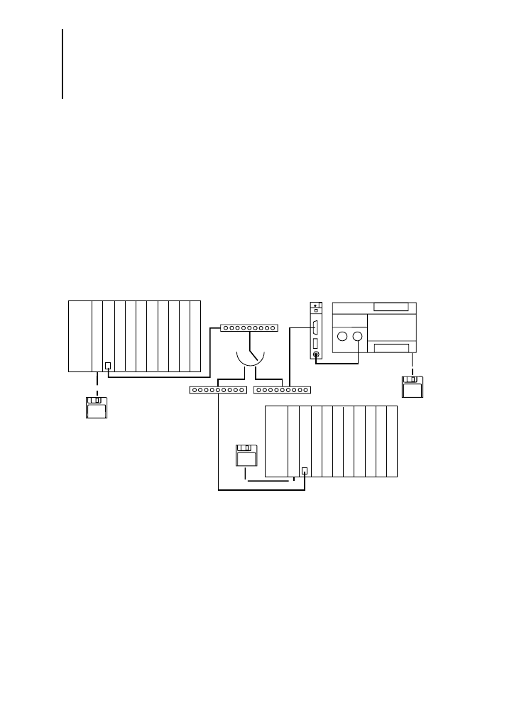
Figure 2: Telecontrol system with PS 416 components and
dial-up line configuration
a Central station – primary station / secondary station
b Dial-up modem
c Dial-up line
d Substation – primary station / secondary station
S 40-AM-TD
ZB 4-254-KB1
b
b
b
a
c
PS 4-200
d
ZB 4-501-TC1
S 40-AM-TD
S 40-AM-TD
CPU PS 416
PS 416-TCS-200
PS 416-CPU-400
PS 416-TCS-200
d
Other manuals (AWBs)
7
0
8
/97
AW
B
27
-1
29
8-
GB
In the case of the leased line all substations are
permanently connected to the central station.
If more than one secondary station is addressed via
the leased line only point-to-point leased modems
(party line) may be used. The central station will in
this case always be a primary station and the
substations always secondary stations. This makes it
possible for the central station to send messages to
all substations simultaneously.
Only the central station can initiate communication.
A substation cannot autonomously initiate
communication with the central station or with
another substation.
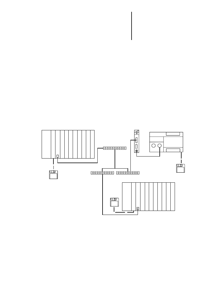
Figure 3: Telecontrol system with PS 416 components and
leased line configuration
a Central station – primary station
b Modem (party line)
c Substation – secondary station
S 40-AM-TL
b
b
b
a
PS 4-200
c
ZB 4-501-TC1
S 40-AM-TL
S 40-AM-TL
PS 416-TCS-200
CPU PS 416
PS 416-TCS-200
c
CPU PS 416
ZB 4-254-KB1

Setting Up A Telecontrol
Station With The PS 416
Controller
8
0
8
/97
AW
B
27
-1
29
8-
GB
Procedure
The following procedure is recommended for
connecting the PS 416 to a telecontrol system.
E Define all requirements made on the telecontrol
system – for example, data security, number of
stations, and so on. A detailed description will be
found in the “Guide to telecontrol” manual.
E Select the application module which matches
your requirements. Relevant factors here include:
station type (modular – compact), station class
(primary – secondary), number of stations.
E Configure the interface parameters for the
PS 416-TCS-200 in the application module. See
Chapter 4, Configuration.
E Adjust the transmission parameters where
necessary to match the requirements of the data
integrity class. See the “Guide to telecontrol”
manual.
E Install the card in the rack. See Chapter 5,
Installation
E Connect the PS 416-TCS-200 to the modem via
the ZB 4-254-KB1 modem cable. See Chapter 5,
Installation
The card is now installed, programmed, configured
and is ready for operation.

9
0
8
/97
AW
B
27
-1
29
8-
GB
2
About The Card
Task of the
PS 416-TCS-200
The PS 416-TCS-200 communication processor is
used for connecting the PS 416 programmable
controller via a modem to a telecontrol system. It
communicates with other telecontrol stations via a
point-to-point modem or dial-up modem.
The card has its own microcontroller. This means that
it handles the communication process autonomously
without taking up any of the capacity of the PS 416
central processing unit.
Hardware and software
requirements
Table 1 provides an overview of the hardware and
software requirements for running the
PS 416-TCS-200 within the PS 416 PLC system.
Table 1: Hardware and software requirements
Software
Programming software
Operating system
Application modules
Sucosoft S 40 Manager, Version 2.0 and
higher for PS 416-CPU-400 Version 1.13 and
higher
S 40-AM-TD Version 1.0 (dial-up line)
S 40-AM-TL Version 1.0 (leased line)
Hardware
Central processing unit
Power supply card:
Subrack
Modem cable
PS 416-CPU-400
PS 416-POW-400
PS 416-POW-410
PS 416-POW-420
PS 416-BGT-400/410/420 or 421 with
PS 416-ZBX-401/402/403 potential
equalisation rail
ZB 4-254-KB1
About The Card
10
0
8
/97
AW
B
27
-1
29
8-
GB
Construction of the
PS 416-TCS-200
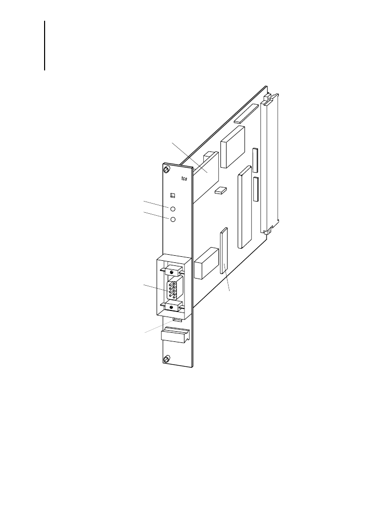
Figure 4: Elements of the PS 416-TCS-200
a Switches S1 / S2
b RS 232 – modem port
c LED (error)
d LED (RxD / TxD)
e Interface module
f System EPROM
rxd/
txd
error
TCS-
a
200
d
c
b
e
f

Communication layers
model
11
0
8
/97
AW
B
27
-1
29
8-
GB
a
Switches S1 / S2
These switches must be left switched off at all times.
b
Port
The 9-pole Sub-D connector is used for connecting
the modem cable. The modem cable is not supplied.
Pin assignments are described in Chapter 3,
Engineering.
c
LED (error)
The LED indicates error messages. See Chapter 7,
Diagnostics
d
LED (RxD / TxD)
The LED indicates the operating status of the card.
See Chapter 7, Diagnostics
e
Interface
In order to ensure interference immunity the data
lines are optocoupled and the interface is supplied
with power via DC / DC converter with electrical
isolation.
Communication layers
model
The communication layers model describes the
relationships between programming software,
function blocks and the requisite hardware.

About The Card
12
0
8
/97
AW
B
27
-1
29
8-
GB
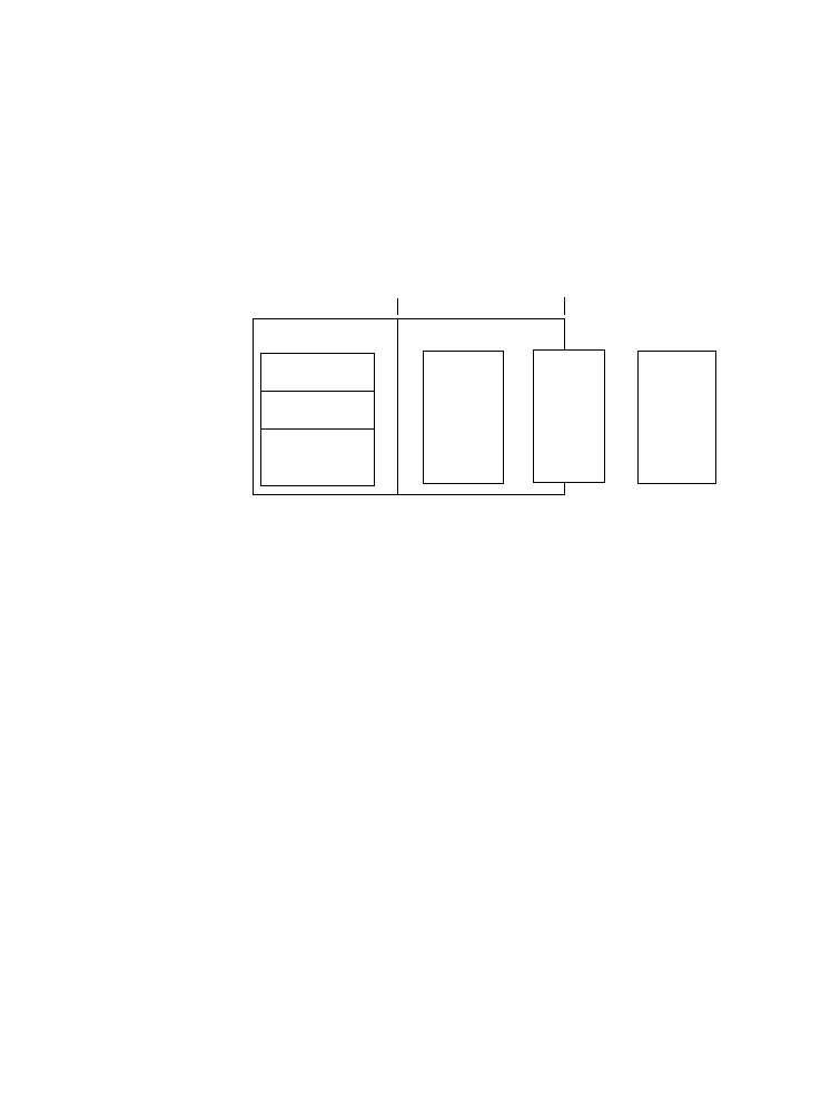
Figure 5: Communication layers model
Application layer
The program data are processed in the application
layer.
Link layer
This layer generates the line telegrams in accordance
with the IEC 870-5 standard and synchronises data
traffic between the station and the telecontrol system.
Physical layer
The electrical signals are formed in this layer in
accordance with the transmission medium used.
A
p
plica
tion layer
Sucosoft S 40
A
ppli
ca-
tion
Routing data
Event control
Data type conversion
Da
ta
modules
Li
nk layer
S 40-AM-TL
S 40-AM-TD
Te
lecont
rol function
blocks
A
ppl
ica
tion modules
Handling services
Address evaluation
Life control
Time-out monitoring
PS 416 programmable controller
PS 416-TCS-200 card
Card
IEC 870-5 primary station point-to-point modem
IEC 870-5 secondary station point-to-point modem
IEC 870-5 dial-up modem
Phys
ical
laye
r
Integrated RS-232 interface
SUB D, 9-pole
Dial-up modem
Primary / secondary
Type 1
Point-to-point modem
Primary
Secondary
Type 2
Type 3

13
0
8
/97
AW
B
27
-1
29
8-
GB
3
Engineering
Number of PS 416-
TCS-200 cards in the
rack
The communication processor works in all PS 416
basic units. The maximum number of
PS 416-TCS-200 cards which can be operated in a
single rack depends on the power consumption. For
this reason a power requirements calculation must
be made in all cases .
Power supply
The card is supplied internally with power at 5 V DC
from the PS 416-POW-400/410/420 power supply
card via the PS 416-rack. For further information
please refer to the Appendix, Technical data.
Terminal assignments
The communication processor is classed as data
terminal equipment (DTE).
The interface has full duplex capability – in other
words, data can be sent and received
simultaneously.
For the connection to the modem use the
ZB 4-254-KB1 modem cable.
Figure 6 shows:
interconnections and the pin assignments for the
9-pole Sub-D front connector
signal numbering as per CCITT recommendation
V24/V28
signal designations as per RS 232C
signal flow

Engineering
14
0
8
/97
AW
B
27
-1
29
8-
GB
Figure 6: Connections of the ZB 4-254-KB1 modem cable
Table 2: Meaning of the signals
Modem
D connector
25-pole plug
PS 416-TCS-200
D connector
9-pole plug
Pin
Pin
1
Protective ground (screening)
—
Not connected
8
DCD
(Data Carrier Detect)
R
1 DCD (Data
Carrier
Detect)
3
TxD
(Transmit Data)
R
2 RxD (Receive
Data)
2
RxD (Receive
Data)
r
3 TxD
(Transmit Data)
20 DSR (Data
Set
Ready)
r
4 DTR
(Data Terminal Ready)
7
SGND
(Signal Ground)
—
5 SGND
(Signal Ground)
6
DTR
(Data Terminal Ready)
R
6 DSR (Data
Set
Ready)
4
CTS
(Clear To Send)
r
7 RTS
(Request To Send)
5
RTS
(Request To Send)
R
8 CTS
(Clear To Send)
22 RI (Ring
Indicator)
R
9 (Signal not supported)
Signal
Meaning
TxD output
Transmit data, in idle state
m 3 V
RxD input
Receive data
SGND
Signal ground
RTS output
The modem is switched to the transmission state and remains in this
state for as long as the On state exists.
RTS is active M 3 V (Request To Send)
CTS input
The modem is ready to send data signals or to receive data for setting up
the connection.
CTS is active
M 3 V (Clear to send)
DTR output
The telecontrol card is ready for operation:
DTR is active
M +3 V, CPU in RUN MODE (Data Terminal Ready)
DSR input
The modem is ready for operation:
DSR is active
M +3 V (Data Set Ready)
DCD input
The modem reports that the transmission link is ready to receive data
(modem carrier frequency is stable).
DCD is active
M 3 V (Data Carrier Detection)

Selection of modem
15
0
8
/97
AW
B
27
-1
29
8-
GB
Selection of modem
You should select modems which have electrical
isolation between the RS 232 and the dial-up or
leased line. This prevents potential equalisation
currents occuring.
Electromagnetic
compatibility
You should note the following engineering
instructions in order to comply with the requirements
of EMC legislation:
E If the inductive and capacitive effects of
electromagnetic fields are to be reduced you will
need to fit the screen in a thorough and careful
manner.
E Connect the screen of the data line to the
protective ground by connecting each end of the
screen to a potential equalisation rail.
E Fit an RF ferrite ring of type PS 416-ZBX-405 to
the lead wire to the data line before the screen
connection.
The RF ferrite sleeve is not supplied with the card. It
can be ordered under type designation
PS 416-ZBX-405.
For the designation of the potential equalisation rail
appropriate for the rack please refer to
AWB 27-1208, PS 416 system.
The modems must also support the 11-bit
signalling format (8E1)
Engineering
16
0
8
/97
AW
B
27
-1
29
8-
GB
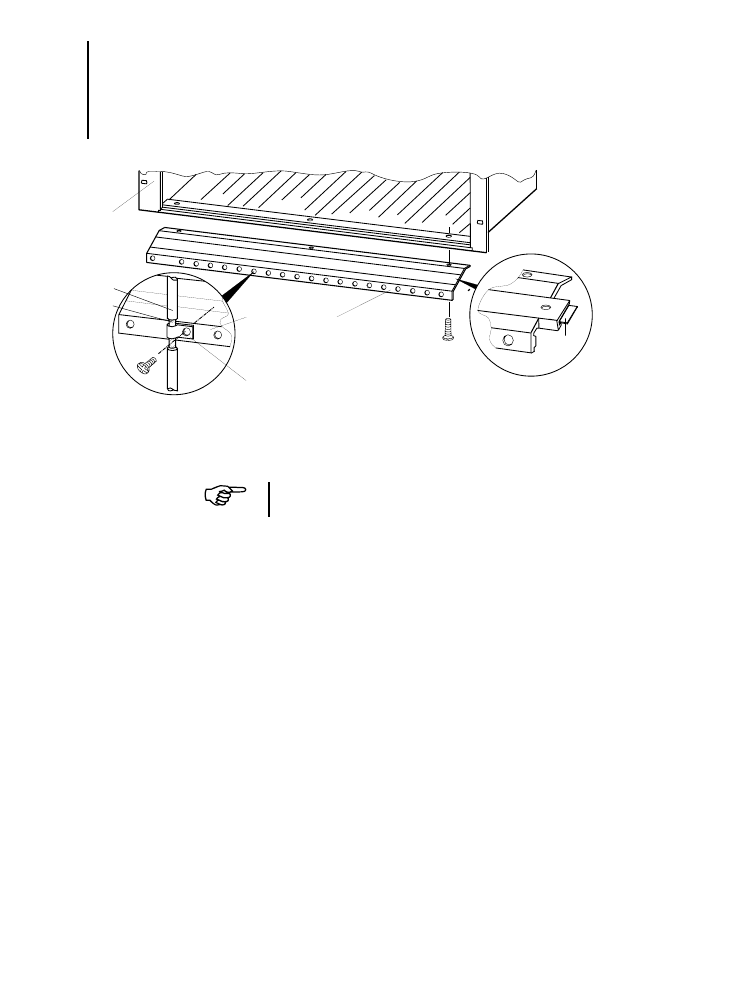
Figure 7: Grounding the signal line of the PS 416-TCS-200
a Signal line of the PS 416-TCS-200
b Screen
a
b
PS 416-BGT-4xx
PS 416-ZBX-40x
PS 416-ZBX-404
c
M4
×
12
M4
×
8
The screen braid must not be interrupted.
Electromagnetic
compatibility
17
0
8
/97
AW
B
27
-1
29
8-
GB
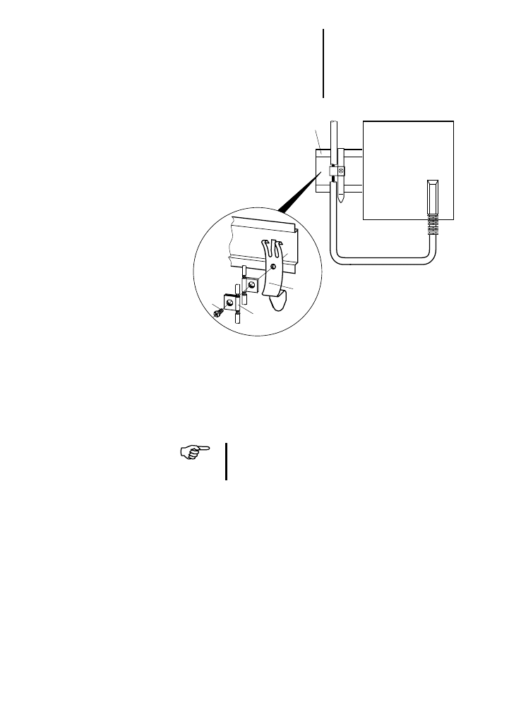
Figure 8: Grounding the signal lines of the modem
a Top-hat rail
b Snap fastener
c Contact clamp
d Screw
e Modem
a
b
d
c
M4
e
The screen braid must not be interrupted.
Items
b
,
c
, and
d
are constituent parts of the
ZB 4-102-KS1 screen earth kit.

18
0
8
/97
AW
B
27
-1
29
8-
GB

19
0
8
/97
AW
B
27
-1
29
8-
GB
4
Configuration
Before you can exchange data over the telecontrol
system for the first time with the PS 416 you will need
to configure each communication processor with the
aid of the device configurator.
E Access the Sucosoft S 40 Topology
Configurator.
E In order to configure the telecontrol card, key a
“0” into the boxes “Line” and “Rack / Station”
since the card can only be operated in the basic
unit of the PS 416.
E Next, in the “Slot / module” box you should
specify which slot the card is occupying.
E In the “Selectable Types” selection box you
should select the option “Card”. From the list of
available cards select the PS 416-TCS-200.
Interface parameters for data transmission
Parameter sets for communication have been
provided in the telecontrol card for the various
modes (leased or dial-up lines). When a service is
called via the application module the appropriate
parameters are used automatically. If these settings are
not the same as the parameters you want you can
change the settings via the application module.
The modified settings are saved in the controller and
when the controller is switched on they are
transferred automatically to the card.

Configuration
20
0
8
/97
AW
B
27
-1
29
8-
GB
Table 3: Default settings for the various modes
Baud rate
You can select from the following baud rates:
300 baud
4800 baud
600 baud
9600 baud
1200 baud
19200 baud
2400 baud
The better the signal quality (the transmission link)
the higher the baud rate you can select for faster data
transmission.
Parity
For additional data security a parity bit can also be
transmitted. Here at the transmitting end it is
possible to expand the character to an even or odd
value. Agreement with the parity setting must be
aimed at with all stations. Note that here not every
combination of data format, number of stop bits and
parity bit is possible – see Table 4
Handshaking RTS/CTS/DSR/DTR/DCD
The handshake lines RTS/CTS/DSR/DTR/DCD are
supported in order to ensure trouble-free
communication between two telecontrol stations via
modem.
Interface parameters (default settings)
Mode
Baud rate
Start bit (fixed value)
Data bit
Parity bit
Stop bit
Dial-up modem
9600
1
8
even
1
Point-to-point modem
1200
1
8
even
1

21
0
8
/97
AW
B
27
-1
29
8-
GB
Data format
7 bit / 8 bit: With 7-bit selection 128 different bit
combinations are available. If you wish to transmit
the entire character set with 256 bit combinations
you will need to select the 8-bit format.
Stop bit
Character format combinations
The PS 416-TCS-200 carries out plausibility checks
and any incompatibilities arising from the character
format combinations will be signalled.
Table 4: Permissible character format combinations
* Default setting of the PS 416-TCS-200
Start bit (fixed value)
Data bit
Parity bit
Stop bit
1
7
none
2
1
7
even
1
1
7
even
1
1
7
even
2
1
7
even
2
1
8
none
1
1
8
none
2
1*
8*
even*
1*
1
8
odd
1

22
0
8
/97
AW
B
27
-1
29
8-
GB

23
0
8
/97
AW
B
27
-1
29
8-
GB
5
Installation
Installing the PS 416-
TCS-200 in the rack
E Make sure that the interface module is firmly
seated in the PS 416-TCS-200.
E Install the PS 416-TCS-200 in the basic unit from
slot 4 onwards.
E Connect the RS 232 interface on the front plate of
the card to the modem. You should use the
ZB 4-254-KB1 modem cable.
E Install the application module; in this regard see
AWB 27-1300-GB and AWB 27-1301-GB.
E Configure the PS 416-TCS-200 with the
application module; see Chapter 4, Configuration.
E Integrate the PC 416-TCS-200 into your
configuration with the aid of the Sucosoft S 40
Topology Configurator.
Operating instructions:
To protect the components from the discharge of
static electricity the operator must discharge
himself electrostatically before touching the
PS 416-TCS-200, its front plate components or
the card.
Warning!
The PS 416-TCS-200 must not be inserted or
removed unless the power supply has been
switched off.

24
0
8
/97
AW
B
27
-1
29
8-
GB
25
0
8
/97
AW
B
27
-1
29
8-
GB
6
Operation
Function of the
PS 416-TCS-200 card
Figure 9: Function of card in a telecontrol station
The card functions in a telecontrol system as a
protocol generator or protocol evaluator. The
application module prepares the user and control
data for the PS 416-TCS-200 communication
processor. The card packs this user data (a
maximum of 220 bytes) into the telecontrol protocol
and sends it to the modem via the integrated RS-232
interface.
The received data is evaluated according to the
telegram protocol used. The application module in
the central processing unit evaluates this data and
makes it available to the user for further processing.
Programmable controller
User program
Application module
PS 416-TCS-200
Protocol
Protocol
Data
generation
evaluation
interface
mission
equipment
PS 416
↔
↔
↔
Data trans-
(modem)
Data terminal equipment (DTE)

Operation
26
0
8
/97
AW
B
27
-1
29
8-
GB
Startup behaviour
Both cold starts and warm starts are possible.
Cold start
Once the PS 416 has been switched on or a cold
restart signal has been received from the PS 416, the
activities of the communication processor begin with
the self-test. Here the PS 416-TCS-200 checks the
functional readiness of the interface module and of
the RAM memory modules.
The operating system will enter an error message in
the DPRAM should one of the following errors occur:
faulty operating system EPROM (where
detectable)
faulty RAM
faulty DPRAM (where detectable)
interface module not plugged in
In the event of such an error the user will receive the
corresponding fault message via the red front panel
LED when the program starts.
If there is none such error, the program logic
assumes that a cold start has taken place and sets
up a configuration which corresponds to the
system’s own default parameters. This default
configuration (leased line) includes a transmission
rate of 1200 baud, a data format of 8 data bits, even
parity with one stop bit as well as the characteristics
of a secondary station with a FT 1.2 message format.
The PS 416-TCS-200 now waits for new parameters
or the command to exchange data using the existing
default parameters.

Shutdown behaviour
27
0
8
/97
AW
B
27
-1
29
8-
GB
Warm start
If the PS 416-TCS-200 receives a reset command
from the application card without a cold start signal
from the central processing unit of the PS 416, the
communication processor stops all jobs which have
started and re-initialises itself with the aid of the user
parameters.
If there is no parameter error, the operating system of
the PS 416-TCS-200 assumes a warm start.
Shutdown behaviour
A drop in the power supply is communicated to the
communication card via a control line. In this case
transmit and receive operation via the serial interface
is aborted. All data which still needs to be sent and
data which has already been received is discarded.

28
0
8
/97
AW
B
27
-1
29
8-
GB

29
0
8
/97
AW
B
27
-1
29
8-
GB
7
Diagnostics
Once the power supply has been switched on and
the self-test has run successfully the green front
panel LED “TxD / RxD” comes on and stays on.
The current operating status can be read off from the
two LEDs; see table.
Table 5: LED function during operation
Green data transfer LED
’TxD / RxD’
Red error LED ’ERR’
Card and bus interconnection status
On
Off
PS 416-TCS-200 is in coupled operation
No data exchange
Flashing
Off
PS 416-TCS-200 is exchanging data
The flashing mirrors the rhythm of the incoming
and outgoing characters.
Off
On
Hardware fault or defective initialization
No data exchange
Off
Flashes at a frequency of 2 Hz
Faulty or incorrectly initialised interface module

30
0
8
/97
AW
B
27
-1
29
8-
GB

31
0
8
/97
AW
B
27
-1
29
8-
GB
Appendix
Technical data
Data interface
RS 232, V24/V28
9-pole SUB-D connector for modem connection
Handshake lines
RTS, CTS, DCD, DTR, DSR
Data transmission protocol
FT 1.2, FT 3 asynchronous
Maximum amount of user data in the
telecontrol transmission protocol
220 bytes
Maximum amount of user data in the
telecontrol transmission protocol
250 bytes
Electromagnetic compatibility (EMC)
Transmission procedure
Asynchronous, choice of protocol
Data transmission rate
300, 600, 1200, 2400, 4800, 9600, 19 200 baud
Transmission link
RS 232, maximum cable length 2 m
Recommended cable
RS 232 with control lines: eight-conductor cable, screened;
max. cable length 2 m
Power consumption
0.83 A (5 V DC)
Power loss
Max. 4.2 W
Ambient temperature
0 to +55 °C
Transportation and storage temperature
–20 to +70 °C
Cards
4 space units (1 slot)
Format
Euroformat (160
u 100 mm)
Weight
approx. 180 g

Appendix
32
0
8
/97
AW
B
27
-1
29
8-
GB
Glossary
Application module
Application modules are programs or parts of
programs for the PLC or PC which support a function
in an application or which execute it entirely.
Application modules provide ready-made solutions
for the most varied applications.
Assymmetrical configuration
Configurations of telecontrol stations which consist
of primary and secondary stations are referred to as
asymmetrical configurations.
Asynchronous transmission
Each message character is synchronised
individually, usually by start and stop elements.
Central station
The station which remotely monitors substations
and / or remotely controls them.
Characters
Agreement regarding the data format, for example,
1 start bit, 8 data bits, 1 parity bit, 1 stop bit; i.e. 1
character = 11 bits.
General information on the electromagnetic compatibility (EMC) of programmable controllers
Emission
EN 55 011/22 Class A
Immunity
ESD
EN 61 000-4-2
Contact discharge
Air discharge
4 kV
8 kV
RFI
ENV 50 140
AM/PM
10 V/m
Burst
EN 61 000-4-4
Power supply/digital I/O
Analogue I/O, field bus
2 kV
1 kV
Surge
ENV 50 142
Digital I/O, assymmetrical
DC supply, assymmetrical
DC supply, symmetrical
AC supply, assymmetrical
AC supply, symmetrical
0.5 kV
1 kV
0.5 kV
2 kV
1 kV
Line-conducted
interference
ENV 50 141
AM
10 V

Glossary
33
0
8
/97
AW
B
27
-1
29
8-
GB
Dial-up line
A transmission line which can be used after dialling.
DTE
Data Terminal Equipment may include computers,
terminals or other input or output devices. A DTE
which transmits data is referred to as a data source.
A DTE which receives data is referred to as a data
sink.
DTE
Data transmission equipment; see also Modem
Handshake
Defined sequence of signals for setting up and
checking a connection.
ISO / OSI
The ISO / OSI model describes a model for
classifying data transmission and processing
between two computers.
Leased line
A non-switched transmission line.
Modem
Abbreviation for “modulator-demodulator”. Device
which converts digital signals into analog signals and
vice versa.
Parity
Method of providing security for data – a check bit is
attached to every character.
Party line configuration
A configuration whereby the central station is
connected to more than one substation via a shared
transmission path in such a way that only one
substation at a time can send data to the central
station. The central station can send data either to
one or more substations. General messages can be
sent to all substations simultaneously.

Appendix
34
0
8
/97
AW
B
27
-1
29
8-
GB
Primary station
Station which initiates data transportation.
Secondary station
A station which replies to a data request from a
primary station.
Substation
A station which is monitored or monitored and
controlled by a central station.
Symmetrical configuration
Configurations of telecontrol stations which consist
of stations with equal rights are referred to as
symmetrical configurations. The stations in these
configurations combine the properties of primary
and secondary stations.
Telecontrol
Telecontrol is the monitoring and control of spatially
widely distributed processes by means of coded bit-
serial data transmission.
Telecontrol configuration
The combination of telecontrol stations and the
transmission paths between the stations.
Telecontrol station
Central station or substation within a telecontrol
system.
Telecontrol station
A telecontrol system is used for controlling and
monitoring processes which are spatially widely
distributed.
The system includes all equipment and functions for
data acquisition, processing, transmission and
display of the requisite process information.

35
0
8
/97
AW
B
27
-1
29
8-
GB
Index
A
Application modules ........................................................ 9
B
Baud rate ....................................................................... 20
C
Central processing unit .................................................... 9
Character format combinations ..................................... 21
Cold restart .................................................................... 26
Communication layers model ........................................ 11
Configuration ................................................................. 19
CTS ................................................................................ 14
D
Data format .................................................................... 21
DCD ............................................................................... 14
Default settings .............................................................. 20
Diagnostics .................................................................... 29
Dial-up line ....................................................................... 5
DSR ................................................................................ 14
DTR ................................................................................ 14
E
Electromagnetic compatibility ....................................... 15
G
Glossary ......................................................................... 32
H
Handshaking .................................................................. 20
Hardware and software requirements ............................. 9
I
Installation ...................................................................... 23
Interface ......................................................................... 11
Interface parameters ...................................................... 19

Index
36
0
8
/97
AW
B
27
-1
29
8-
GB
L
Leased line ....................................................................... 7
LED (error) ...................................................................... 11
LED (RxD / TxD) ............................................................. 11
LED function ................................................................... 29
M
Modem ............................................................................. 5
Grounding the signal line ............................................ 17
Selection ..................................................................... 15
Modem cable ............................................................... 5, 9
O
Operating system ............................................................. 9
Operation ........................................................................ 25
P
Parity .............................................................................. 20
Party line ........................................................................... 7
Point-to-point dedicated modem ..................................... 7
Port ................................................................................. 11
Power supply .................................................................. 13
Power supply card ........................................................... 9
Primary station ................................................................. 6
Protective earth .............................................................. 14
PS 416-TCS-200
Construction ............................................................... 10
Function ...................................................................... 25
Installation in rack ....................................................... 23
Number in rack ........................................................... 13
S
Secondary station ............................................................ 6
SGND ............................................................................. 14
Shutdown behaviour ...................................................... 27
Signal line
Grounding ................................................................... 16
Startup behaviour ........................................................... 26

Index
37
0
8
/97
AW
B
27
-1
29
8-
GB
Stop bit .......................................................................... 21
Subrack ............................................................................ 9
Switches S1 / S2 ............................................................ 11
T
Technical data ................................................................ 31
Terminal assignments .................................................... 13
TxD ................................................................................. 14
U
User data ....................................................................... 25
W
Warm start ..................................................................... 27
Document Outline
- Hardware and Engineering
- Before commencing the installation
- Contents
- About This Manual
- 1 Setting Up A Telecontrol Station With ThePS416 Controller
- 2 About The Card
- 3 Engineering
- 4 Configuration
- 5 Installation
- 6 Operation
- 7 Diagnostics
- Appendix
- Index
Wyszukiwarka
Podobne podstrony:
PS4 PS 416 NET 440, Master h1330g
PS4 PS 4 271 MM1 h1364g
h1239g PLC PS4 416
h1239g PLC PS4 416
h1244g MODBUS PLC PS4 416
1 72 Short 330 200 Bobs Card Models 2007
PS VI
PS spolecznosc lokalna 3
PS 1 Psychologia społeczna wstep
200 Faszyzm 2id 21545 ppt
PS Organiz 11
PS Komunikacja 910
Semin 3 ST Ps kl Stres
PS IV
w2 ps poznawcza
43 Appl Phys Lett 88 013901 200 Nieznany (2)
EC08 FPC PS TIG FPC Outbrief (9May08)
więcej podobnych podstron