
Hardware and Engineering
LE 4-622-CX1
Local Expansion Module for Incremental Encoders
LE 4-633-CX1
Local Expansion Module for Absolute Encoders
03/98 AWB 2700-1324 GB
1st published 1998, edition 03/98
© Moeller GmbH, Bonn
Author:
Werner Albrecht
Editor:
Thomas Kracht
Translator: Terence Osborn
All brand and product names are trademarks or
registered trademarks of the owner concerned.
All rights reserved, including those of the
translation.
No part of this manual may be reproduced in any
form (printed, photocopy, microfilm or any
otherprocess) or processed, duplicated or
distributed by means of electronic systems without
written permission of Moeller GmbH, Bonn.
Subject to alterations without notice.

Warning!
Dangerous electrical voltage!
Before commencing the installation
●
Disconnect the power supply of the
device.
●
Ensure that devices cannot be
accidentally restarted.
●
Verify isolation from the supply.
●
Earth and short circuit.
●
Cover or enclose neighbouring units that
are live.
●
Follow the engineering instructions
(AWA) of the device concerned.
●
Only suitably qualified personnel in
accordance with EN 50 110-1/-2
(VDE 0105 Part 100) may work on this
device/system.
●
Before installation and before touching
the device ensure that you are free of
electrostatic charge.
●
The functional earth (FE) must be
connected to the protective earth (PE) or
to the potential equalisation. The system
installer is responsible for implementing
this connection.
●
Connecting cables and signal lines
should be installed so that inductive or
capacitive interference do not impair the
automation functions.
●
Install automation devices and related
operating elements in such a way that
they are well protected against
unintentional operation.
●
Suitable safety hardware and software
measures should be implemented for the
I/O interface so that a line or wire
breakage on the signal side does not
result in undefined states in the
automation devices.
●
Ensure a reliable electrical isolation of
the low voltage for the 24 volt supply.
Only use power supply units complying
with IEC 60 364-4-41 (VDE 0100
Part 410) or HD 384.4.41 S2.
●
Deviations of the mains voltage from
the rated value must not exceed the
tolerance limits given in the speci-
fications, otherwise this may cause
malfunction and dangerous operation.
●
Emergency stop devices complying with
IEC/EN 60 204-1 must be effective in all
operating modes of the automation
devices. Unlatching the emergency-stop
devices must not cause restart.
●
Devices that are designed for mounting
in housings or control cabinets must only
be operated and controlled after they
have been installed with the housing
closed. Desktop or portable units must
only be operated and controlled in
enclosed housings.
●
Measures should be taken to ensure the
proper restart of programs interrupted
after a voltage dip or failure. This should
not cause dangerous operating states
even for a short time. If necessary,
emergency-stop devices should be
implemented.
●
Wherever faults in the automation
system may cause damage to persons
or property, external measures must be
implemented to ensure a safe operating
state in the event of a fault or malfunction
(for example, by means of separate limit
switches, mechanical interlocks etc.).

1
03/
98 AW
B
2700-
1324 G
B
1 About The Local Expansion Modules
Electromagnetic compatibility (EMC)
Terminal assignment on the data cable
Terminal assignment for the SSI data cable
on the LE 4-633-CX1
Mounting in the switch cabinet

2
03/
98 AW
B
2700-
1324 G
B

3
03/
98 AW
B
2700-
1324 G
B
About This Manual
Other manuals
The LE 4-622-CX1 and LE 4-633-CX1 local
expansion modules are used in conjunction with the
PS 4-200 and PS 4-400 locally expandible compact
PLCs.
Consequently, some of the topics covered in this
manual are closely or directly linked to the PS 4.
More detailed information is given in the
corresponding manuals:
Hardware and Engineering for the PS 4-200,
AWB 27-1184-GB
Hardware and Engineering for the PS 4-400,
AWB 27-1240-GB
Symbols
Two symbols are used throughout this manual and
have the following meanings:
왘 Indicates handling instructions
Draws your attention to interesting tips and
additional information

4
03/
98 AW
B
2700-
1324 G
B

5
03/
98 AW
B
2700-
1324 G
B
1
About The Local Expansion Modules
LE 4-622-CX1
Task
The LE 4-622-CX1 is used to position, detect the
position of and count fast pulses.
Special features
Table 1: Special features of the LE 4-622-CX1
Number of channels
(counter)
2
Counter range
24 bits: 0 to FF FFFF hex
0 to 16,777,215 decimal
Mode
(set individually for
each channel)
1: Positioning system for 5 V incremental
encoders
2: Positioning system for 24 V incremental
encoders
3: Fast counter for 24 V signals
Counter frequency
Max. 300 kHz (5 V inputs)
Max. 30 kHz (24 V inputs)
Preferred
applications
Position detection for positioning tasks
Power supply to the
encoder
External via ZB 4-122-KL1 twin-level terminal
block
About The Local Expansion
Modules
6
03/
98 AW
B
2700-
1324 G
B
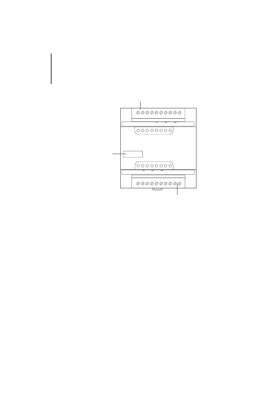
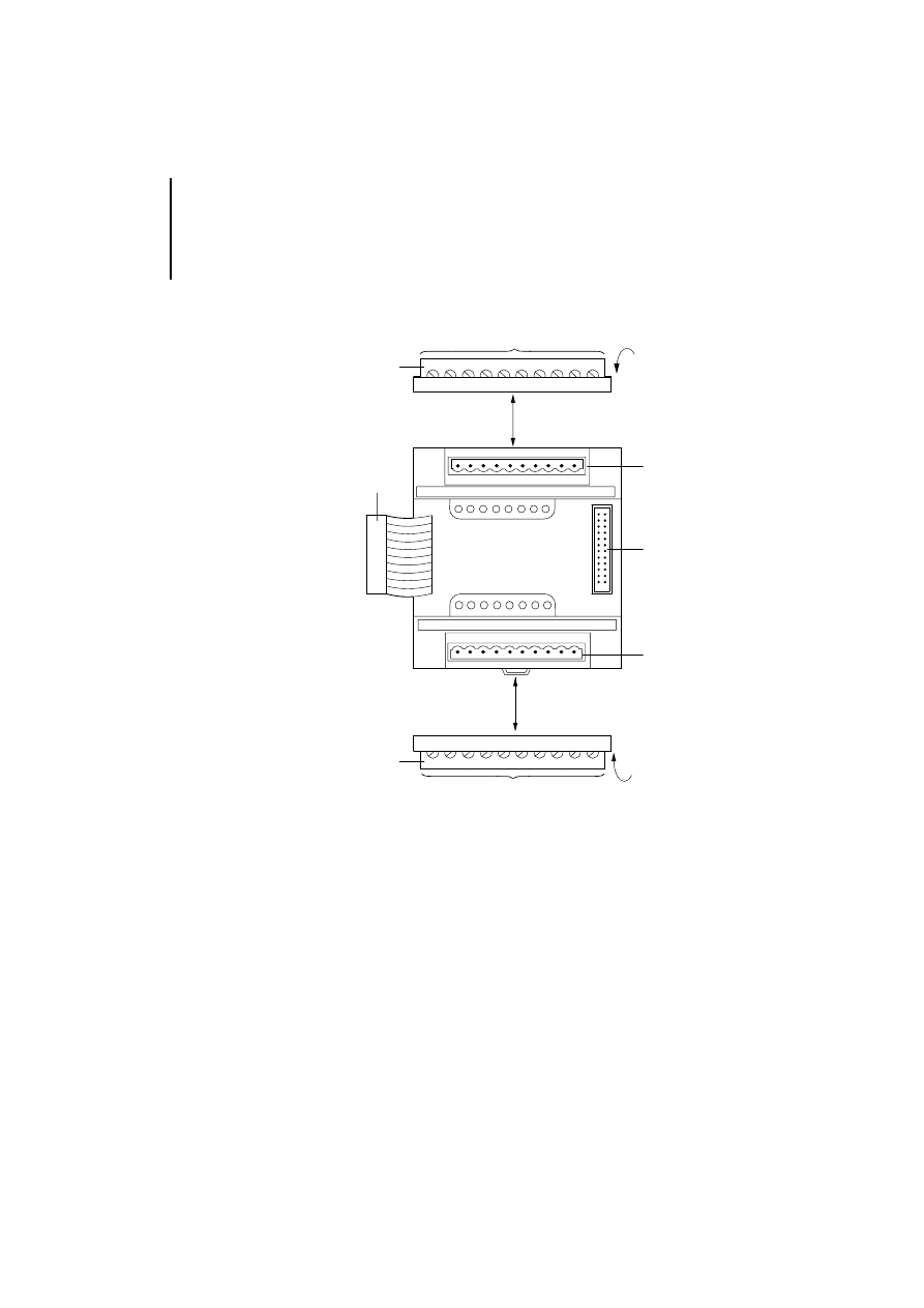
Setup
Figure 1: Structure of the LE 4-622-CX1
햲 Plug-in screw terminal for the data cables
A
R
LE4-622-CX1
Input
CH0
Input
CH1
GND R Y X
R
B
A
GND
R
Y
X
R
R
B
B
A
B
A
햳
햳
햲

LE 4-633-CX1
7
03/
98 AW
B
2700-
1324 G
B
LE 4-633-CX1
Task
The LE 4-633-CX1 is used to position or to
accurately determine the absolute position of drive
shafts. The absolute position values are transferred
by serial synchronous transmission.
Special features
Table 2: Special features of the LE 4-633-CX1
Number of SSI channels
3
Transmission speed
125 kHz or 250 kHz
Preferred applications
Positioning tasks
Data code
Binary or Gray
Data format
25-bit (single and multi-turn)
Wire break detection on signal
line D+ and D-
Yes
Power supply to the
absolute encoder
External via ZB 4-122-KL1 twin-
level terminal block
About The Local Expansion
Modules
8
03/
98 AW
B
2700-
1324 G
B
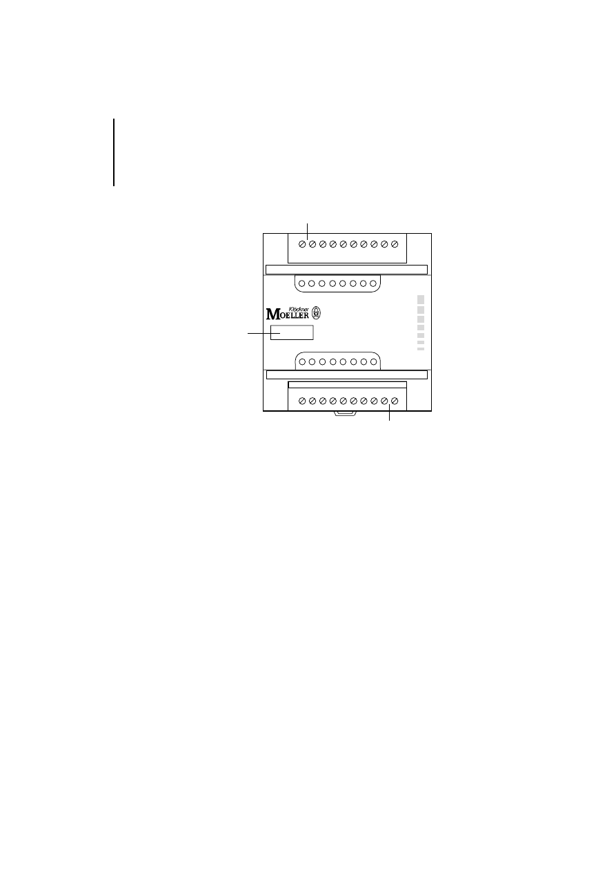
Setup
Figure 2: Setup of the LE 4-633-CX1
햲 Plug-in screw terminal for the clock and data cables
햲
LE4-633-CX1
햳
1D+ 1D– 1T+ 1T– 2D+ 2D– 2T+ 2T–
햳
3T– 3T+ 3D– 3D+

9
03/
98 AW
B
2700-
1324 G
B
2
Engineering
Electromagnetic
compatibility (EMC)
Please read the engineering notes in the “EMC
Engineering Guidelines for Automation Systems”
manual (AWB 27-1287-GB).
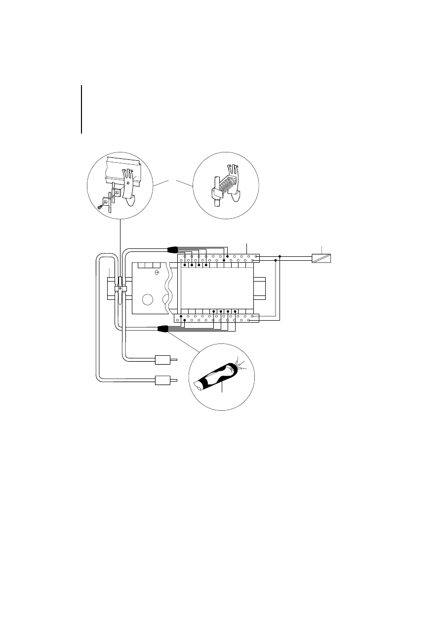
German EMC law
To ensure that you conform to the requirements of
the EMC law, please note the following points (see
also Figure 3):
왘 Lay the screened data cable on the left or right of
the module by the shortest route and produce a
low impedance connection between the screen
braid and the reference potential over a large
contact area
햲. The accessories you will need
are listed in the Appendix.
왘 Use the ZB 4-122-KL1 twin-level terminal block
햳 for the power supply to the encoder.
왘 Follow the manufacturer’s instructions for the
power supply unit
햴 for the encoder (absolute
encoder, incremental encoder, etc).
왘 Insulate the end of the screen braid as closely as
possible to point at which the signal line
햵 enters
the module.
Engineering
10
03/
98 AW
B
2700-
1324 G
B
Figure 3: EMC measures
햲
햳
24 V
0 V
LE 4-622/633-CX1
햵
PS 4
Geber
Geber
햴
햲
M4
Overview of the terminals
11
03/
98 AW
B
2700-
1324 G
B
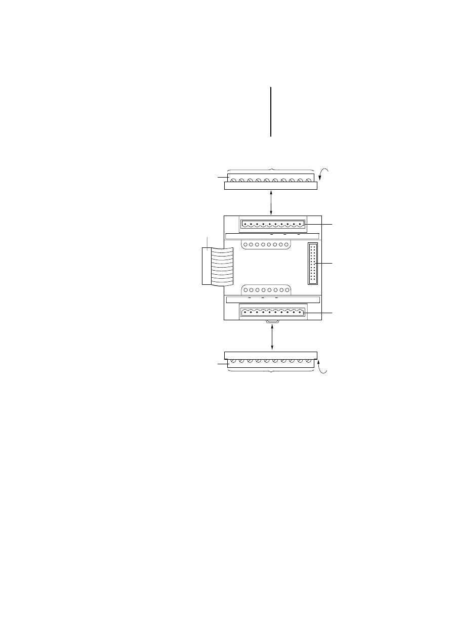
Overview of the
terminals
LE 4-622-CX1
Figure 4: Overview of the terminals on the LE 4-622-CX1
햲 Plug connector for the LE bus
햳 Plug-in screw terminals
햴 Conductor cross-sections:
flexible with ferrule 0.22 mm² to 1.5 mm²
solid 0.22 mm² to 2.5 mm²
햵 Terminal for channel 0
햶 Plug connector for LE bus
햷 Terminal for channel 1
햵
햶
햲
햳
햴
햳
햴
R
B
A
GND R Y X
R
B
A
GND
R
Y
X
R
R
B
B
A
A
햷
Engineering
12
03/
98 AW
B
2700-
1324 G
B
LE 4-633-CX1
Figure 5: Overview of the terminals on the LE 4-633-CX1
햲 Plug connector for LE bus
햳 Plug-in screw terminals
햴 Conductor cross-sections:
flexible with ferrule 0.22 mm² to 1.5 mm²
solid 0.22 mm² to 2.5 mm²
햵 Terminal for channel 1 and channel 2
햶 Plug connector for LE bus
햷 Terminal for channel 3
햲
햳
햴
햳
햴
3T– 3T+ 3D– 3D+
1D+ 1D– 1T+ 1T– 2D+ 2D– 2T+ 2T–
햵
햶
햷

Terminal assignment on the
data cable
13
03/
98 AW
B
2700-
1324 G
B
Terminal assignment
on the data cable
LE 4-622-CX1
Three different modes or connection types can be
used for each counter channel to suit various
applications:
Mode 1:
Positioning system for 5 V incremental encoders
Mode 2:
Positioning system for 24 V incremental encoders
Mode 3:
Fast counter for 24 V pulse generators
Use the Parameter Editor of the Sucosoft S 30-S4 or
S 40 software to select the mode. The mode is
adopted when the program starts up and cannot be
changed while the program is running. The mode can
only be changed in the Parameter Editor.
In modes 1 and 2, the signal is quadrupled internally.
This means that the rising and falling signal edges are
evaluated at inputs A and B or X and Y.
A/X
B/Y
internes
Zählsignal bei
4fach-Auswertung
Engineering
14
03/
98 AW
B
2700-
1324 G
B
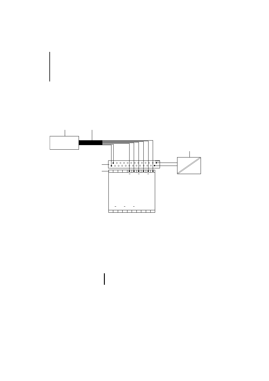
Positioning system for 5 V incremental encoders
With this type of connection, the 5 V pulses of an
incremental encoder are counted. The incremental
encoder should be connected to LE 4-622-CX1 as
shown in Figure 6 below:
Figure 6: Connection of a 5 V incremental encoder
햲 Incremental encoder
햳 Screened data cable
햴 Power supply unit for the incremental encoder (follow
the manufacturer’s instructions)
햵 Plug-in screw terminal for connecting the data cable
햶 ZB 4-122-KL1 twin-level terminal block for connecting
the power supply
The incremental encoder sends the following 5 V
signals:
GND R
Y
X
R
R
B
B
A
A
Input
CH 0
LE 4-622-CX1
Input
CH 1
A
B
B
R
R
X
Y
R GND
A
햲
햳
햶
햵
햴
In this mode, the LE 4 needs antivalent signals in
order to operate.
Terminal assignment on the
data cable
15
03/
98 AW
B
2700-
1324 G
B
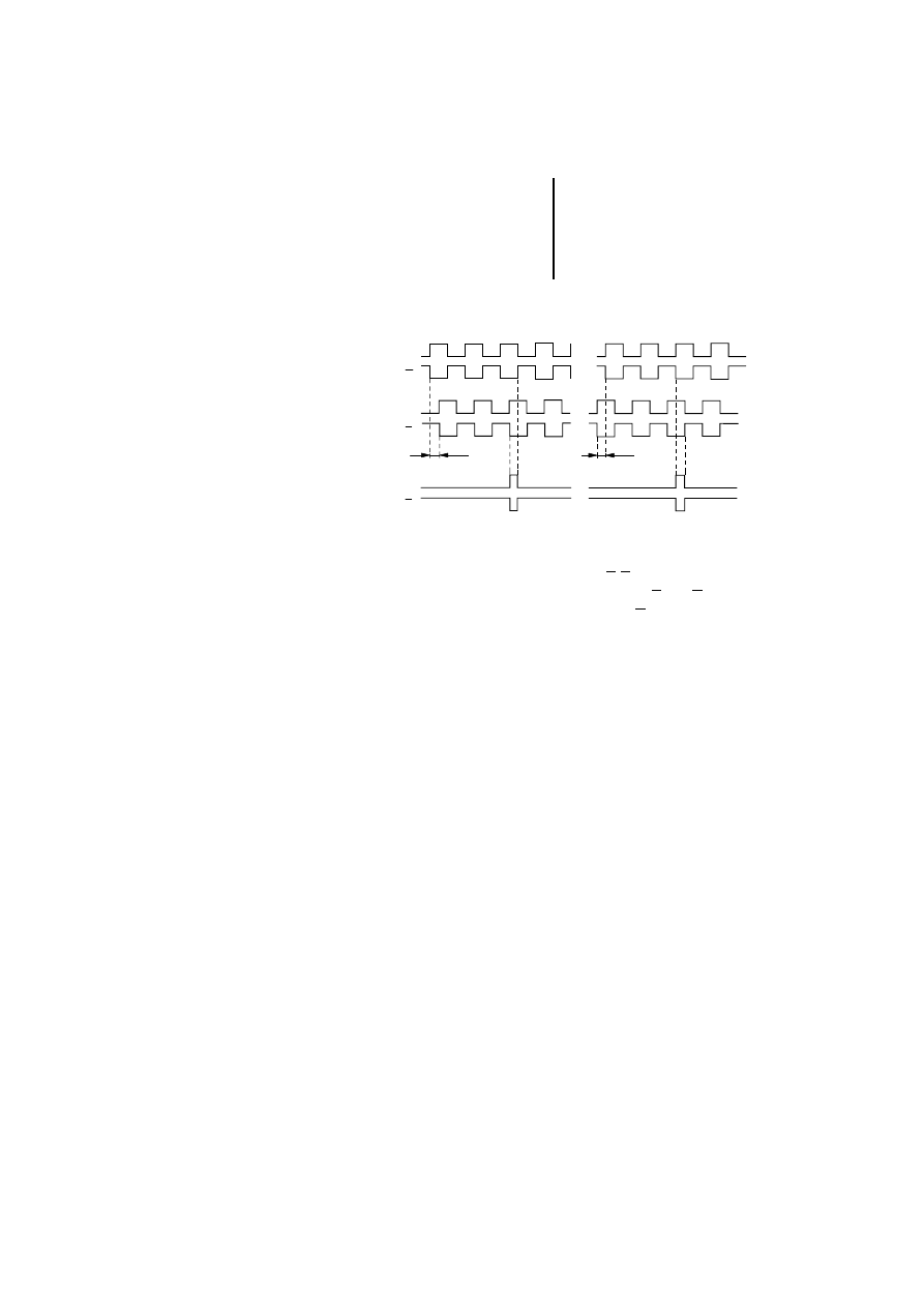
Figure 7: Signals from a 5 V incremental encoder
The signals at inputs A/B and A/B are offset by 90°
so that the direction can be detected. A and B are the
antivalent signals of A and B. R or R (antivalent
signal) is the reference signal which the encoder
sends once every revolution, for example.
If a wire break occurs on one of these cables, an error
message is signalled at the “Error” output of the
function block.
Select the “Incremental encoder 5 V DC (mode 1)”
setting in the Parameter Editor.
vorwärtszählen
rückwärtszählen
A
A
B
B
R
R
90˚
90˚
Engineering
16
03/
98 AW
B
2700-
1324 G
B
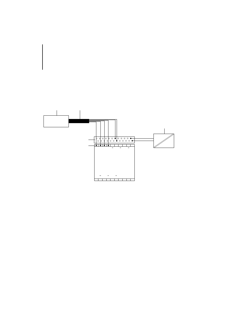
Positioning system for 24 V incremental encoders
With this type of connection, the 24 V pulses of an
incremental encoder are counted. The incremental
encoder should be connected to LE 4-622-CX1 as
shown in Figure 8 below.
Figure 8: Connection of a 24 V incremental encoder
햲 Incremental encoder
햳 Screened data cable
햴 Power supply unit for the incremental encoder (follow
the manufacturer’s instructions)
햵 Plug-in screw terminal for connecting the data cable
햶 ZB 4-122-KL1 twin-level terminal block for connecting
the power supply
GND R
Y
X
R
R
B
B
A
A
Input
CH 0
LE 4-622-CX1
Input
CH 1
A
B
B
R
R
X
Y
R GND
A
햲
햳
햶
햵
햴
Terminal assignment on the
data cable
17
03/
98 AW
B
2700-
1324 G
B
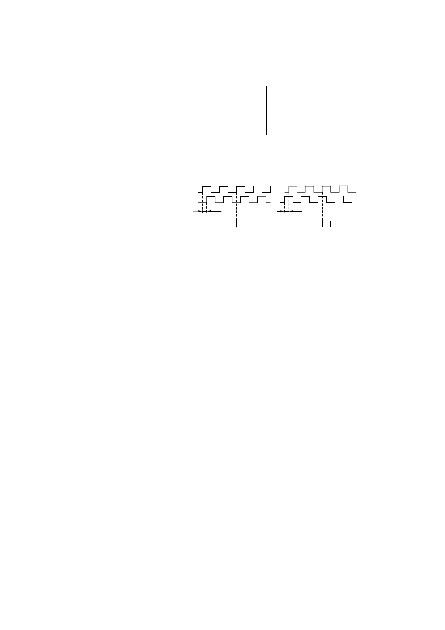
The incremental encoder sends the following 24 V
signals
:
Figure 9: Signals from a 24 V incremental encoder
The signals at LE inputs X/Y are offset by 90° so that
the direction can be detected. R is the reference
signal which the encoder sends once every
revolution, for example.
Select the “Incremental encoder 24 V DC (mode 2)”
setting in the Parameter Editor.
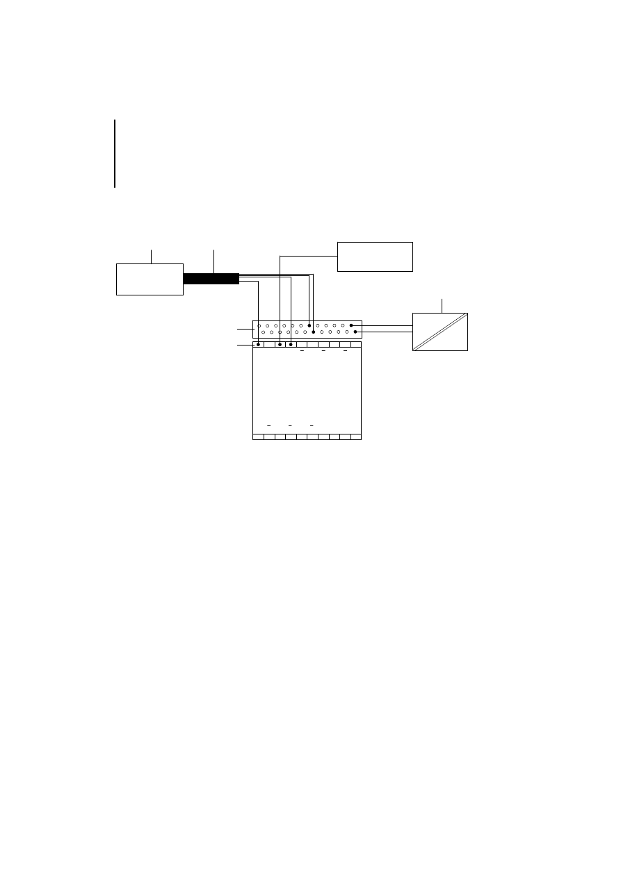
Fast counter for 24 V pulse generators
With this type of connection, the 24 V pulses from a
pulse generator are counted. The pulse generator,
X
Y
90°
R
90°
vorwärtszählen
rückwärtszählen
Engineering
18
03/
98 AW
B
2700-
1324 G
B
such as an initiator, should be connected to the
LE 4-622-CX1 as shown in Figure 10 below.
Figure 10: Connection of a 24 V pulse generator
햲 Pulse generator
햳 Screened data cable
햴 Power supply unit for the incremental encoder (follow
the manufacturer’s instructions)
햵 Plug-in screw terminal for connecting the data cable
햶 ZB 4-122-KL1 twin-level terminal block for connecting
the power supply
Richtungssignal
0 V = vorwärtszählen
24 V = rückwärtszählen
GND R
Y
X
R
R
B
B
A
A
Input
CH 0
LE 4-622-CX1
Input
CH 1
A
B
B
R
R
X
Y
R GND
A
햲
햳
햶
햵
햴

Terminal assignment for the
SSI data cable on the
LE 4-633-CX1
19
03/
98 AW
B
2700-
1324 G
B
The pulse generator sends 24 V counter pulses to LE
input X. The counter level changes in response to a
positive edge. The counting direction can be
changed using an external switch which acts on LE
input Y:
Up counting
= 0 V at input Y
Down counting = 24 V at input Y
X =
LE input for counter pulses
Y =
LE input for displaying the direction
ZS = Counter level
Select the “Pulse generator 24 V DC (mode 3)”
setting in the Parameter Editor.
Terminal assignment
for the SSI data cable
on the LE 4-633-CX1
The following terminal assignment diagram shows
how to connect an absolute encoder an with SSI
interface
(SSI = Synchronous Serial Interface) to the
LE 4-633-CX1. This local expansion module has
three SSI channels.
X
Y
vorwärts
rückwärts
69
70
71
70
69
68
ZS
Engineering
20
03/
98 AW
B
2700-
1324 G
B
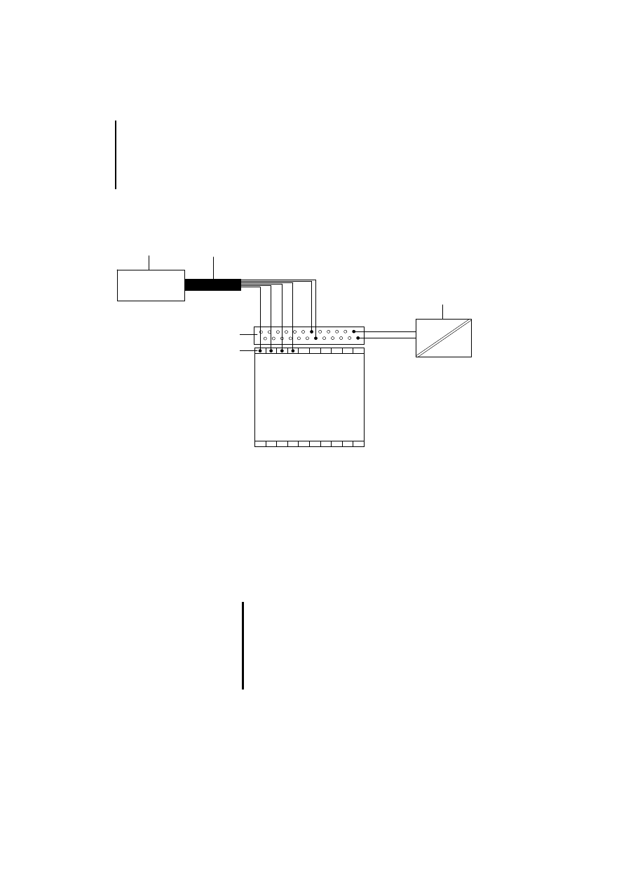
Absolute encoders using either Gray and/or binary
code may be connected.
Figure 11: Connection of an absolute encoder with SSI
interface
햲 Absolute encoder with SSI interface
햳 Screened data cable
햴 Power supply unit for the absolute encoder (follow the
manufacturer’s instructions)
햵 Plug-in screw terminal for connecting the data cable
햶 ZB 4-122-KL1 twin-level terminal block for connecting
the power supply
햲
3T- 3T+ 3D- 3D+
1D+ 1D- 1T+ 1T-
2D+ 2D- 2T+ 2T-
LE 4-633-CX1
햳
햶
햵
햴
Wire the D+ cable of the absolute encoders to
the D+ input on the LE 4-633-CX1. Repeat
accordingly for D–, T+ and T–.
Incorrect timing diagrams may be obtained if
these data cables are swapped over, which can
cause a wire break message to appear on the
PS 4.

Terminal assignment for the
SSI data cable on the
LE 4-633-CX1
21
03/
98 AW
B
2700-
1324 G
B
In contrast to incremental encoders, absolute
encoders can record the precise (absolute) position,
even after a power failure. Either single-turn or multi-
turn absolute encoders can be used, depending on
the distance or angle to be resolved and the required
resolution accuracy. Given the need to detect either
distances or angles, we generally differentiate
between translational (linear motion) and rotational
(rotary motion) position determination.
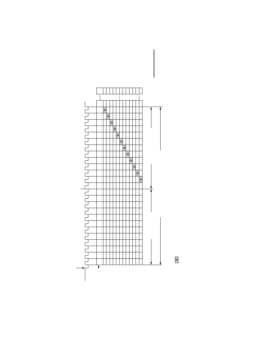
The following diagrams show how the data from the
absolute encoder appears as a bit pattern on the
PS 4 (bit 31 to bit 0). The differences between 25-bit
multi-turn (Figure 12), 21-bit multi-turn (Figure 13)
and 13-bit single-turn (Figure 14) should be noted
since the LE 4-633-CX1 analyses the data in 25-bit
multi-turn format.

Engineering
22
03/
98 AW
B
2700-
1324 G
B
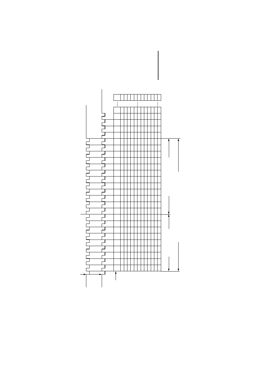
Figure 12 shows the graphical structure of the 25-bit
multi-turn data format in relation to the resolution per
revolution and the number of revolutions.
Bits 6 to 0 always contain pulse value “0”
Terminal assignment for the
SSI data cable on the
LE 4-633-CX1
23
03/
98 AW
B
2700-
1324 G
B
.
0
x
A - 2
A - 20
A + 2
A - 1
A - 4
A - 6
A - 3
31
A + 10
1
23
4
5
67
8
9
10
11
12
13
14
15
16
17
18
19
20
21
22
23
24
25
A + 11
A + 9
A + 8
A + 7
A + 6
A + 5
A + 4
A + 1
A
A - 5
A - 7
A - 8
A - 9
A - 10
A - 11
A - 12
A - 13
A - 14
30
29
28
27
26
25
24
23
22
21
20
19
18
17
16
15
14
13
12
11
10
9
8
76
0
Takt +
Bit-Muster
in der PS 4
LSB:
Niederwertiges Bit
MSB:
H
ö
chstwertiges Bit
Ü
bernahme des momentan anstehenden
W
ertes in das LE 4-633-CX1
A + 3
grau hinterlegte F
elder k
ö
nnen Sonderbits sein!
Anzahl Umdrehung
Parallele
Wink
elinformationen im Gray/Bin
är
-Code
Aufl
ö
sung pro Umdrehung
x
x
x
x
x
x
x
x
x
xxxxxxxxxxxxxxxxxxxx
x
x
x
x
x
x
x
x
x
x
x
x
x
x
x
x
x
x
x
x
x
x
x
x
x
x
x
x
x
x
x
x
x
x
x
x
x
x
x
x
x
x
x
x
x
x
x
x
x
x
x
x
x
x
x
x
x
x
x
x
x
x
x
x
x
x
x
x
x
x
x
x
x
x
x
x
x
x
x
x
x
x
x
x
x
x
x
x
x
x
x
x
x
x
x
x
x
x
x
x
x
x
x
x
x
x
x
x
x
x
x
x
x
x
x
x
x
x
x
x
x
x
x
x
x
x
0
0
0
0
0
0
0
0
0
0
0
00
000
0000
00000
000000
0000000
00000000
000000000
0000000000
0
0
0
0
0
0
0
0
0
0
0
0
0
0
0
0
0
0
0
0
0
0
0
0
0
0
0
0
0
0
0
0
0
0
0
0
0
0
0
0
0
0
0
0
0
0
0
0
0
0
0
0
0
0
0
0
0
0
0
0
0
0
0
0
0
0
0
0
0
0
0
0
0
0
0
0
0
0
0
0
0
0
0
0
0
0
0
0
0
0
0
0
0
0
0
0
0
0
0
0
0
0
F
ig
u
re
1
2
: M
u
lti-
tu
rn
d
a
ta
fo
rm
a
t (2
5
-b
it) fo
r s
yn
c
h
ro
n
o
u
s s
e
ria
l d
a
ta
tra
n
sm
is
si
o
n
w
ith
b
it p
a
tte
rn
in
th
e
P
S
4

Engineering
24
03/
98 AW
B
2700-
1324 G
B
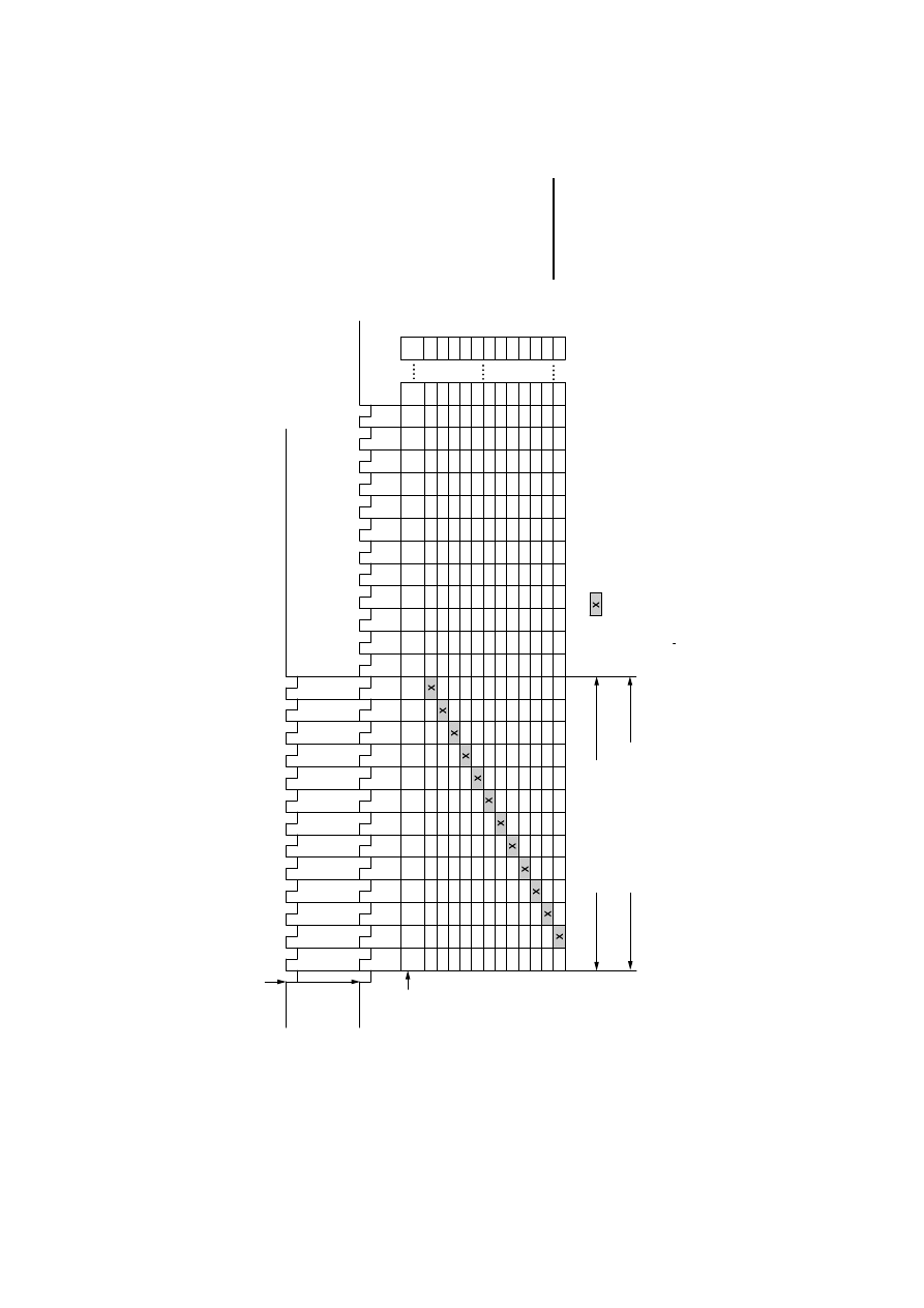
Figure 13 shows the graphical structure of the 21-bit
multi-turn data format in relation to the resolution per
revolution and the number of revolutions.
Only the first 21 bits (bit 31 to bit 11) have to be
evaluated in the PS 4 since the LE 4-633-CX1 reads
the data from the absolute encoder in 25-bit multi-
turn data format. Bits 10 to 7, which have a “?”, do
not have to be evaluated. Bits 6 to 0 always contain
pulse value “0”
Terminal assignment for the
SSI data cable on the
LE 4-633-CX1
25
03/
98 AW
B
2700-
1324 G
B
Takt +
Parallele
Wink
elinformationen im Gray/Bin
är
-Code
Anzahl Umdrehung
Takt +
A -10
A -11
A -12
A -13
A -23
A -17
A -16
A -15
A -14
A - 1
0
0
0
0
0
00
0
0
Aufl
ösung pro Umdrehung
A - 6
ohne Sonderbit
31
A + 7
1
23
4
5
67
8
9
?
?
?
?
?
?
?
?
?
?
?
?
?
?
?
?
?
?
?
?
?
?
?
?
?
?
?
?
?
?
?
?
?
?
?
?
?
?
?
?
?
?
?
?
?
?
?
?
x
10
11
12
13
14
15
16
17
18
19
20
21
22
23
24
25
A + 8
A + 6
A
+ 5
A + 4
A + 3
A
+ 2
A + 1
A
A - 2
A - 3
A - 4
A - 5
A - 7
A - 8
A
- 9
30
29
28
27
26
25
24
23
22
21
20
19
18
17
16
15
14
13
12
11
10
9
8
7
6
0
Multiturn (21 Bit)
1
23
4
5
67
8
9
10
11
12
13
14
15
16
17
18
19
20
21
Multiturn (25 Bit)
Ü
bernahme des momentan anstehenden
W
ertes in das LE 4-633-CX1
Bit-Muster
in der
PS 4
LSB:
Niederwertiges Bit
MSB:
H
öchstwertiges Bit
0
xxxxxxxxxxxxxxxxxxxx xxxxxxxxxxxxxxxxx
x
x
xx
x
x x x
xxx xxx xxx xxx
xx
x
xxxxxxxxxx xxxxxxxxxx xxxxxxxxx xxxxxxxx xxxxxxx xxxxxx xxxxx
xxx xx x
x
0
0
0
0
0
0
0
0
0
0
0
0
0
0
0
0
0
0
0
0
0
0
0
0
0
0
0
0
0
0
0
0
0
0
0
0
0
0
0
0
0
0
0
0
0
0
0
0
0
0
0
0
0
0
0
0
0
0
0
0
0
0
0
0
0
0
0
0
0
0
0
0
0
0
0
0
0
0
0
0
0
0
0
0
0
0
0
0
0
0
0
0
0
0
0
0
0
0
0
0
0
0
0
0
0
0
0
0
0
0
0
0
0
0
0
0
0
0
0
0
0
0
0
0
0
0
0
0
0
0
0
0
0
0
0
0
0
0
0
0
0
0
0
00
F
ig
u
re
1
3
: M
u
lti-
tu
rn
d
a
ta
fo
rm
a
t (2
1
-b
it) fo
r s
yn
c
h
ro
n
o
u
s s
e
ria
l d
a
ta
tra
n
sm
is
si
o
n
w
ith
b
it p
a
tte
rn
in
th
e
P
S
4

Engineering
26
03/
98 AW
B
2700-
1324 G
B
Figure 14 shows the graphical structure of the 13-bit
single-turn data format in relation to the resolution for
one revolution.
Since the LE 4-633-CX1 reads the data from the
absolute encoder in 25-bit multi-turn data format,
only the first 13 bits (bit 31 to bit 19) may be
evaluated in the PS 4. Bits 18 to 7, which have a “?”,
must not be evaluated. Bits 6 to 0 always contain
pulse value "0".
Please also note the data format information
provided by the absolute encoder manufacturer.
Terminal assignment for the
SSI data cable on the
LE 4-633-CX1
27
03/
98 AW
B
2700-
1324 G
B
20
A - 32
0
Aufl
ösung pro Umdrehung
A - 10
A - 13
A - 16
A - 18
Parallele Wink
elinformationen
im Gray/Bin
är
-Code
A - 15
31
A - 2
1
23
4
5
67
8
9
?
x
10
11
12
13
14
15
16
17
18
19
20
21
22
23
24
25
A - 1
A - 3
A
- 4
A - 5
A - 6
A - 7
A - 8
A
- 11
A - 12
A - 14
A - 17
A - 19
A - 20
A - 21
A - 22
A - 23
A - 24
A - 25
A - 26
30
29
28
27
26
25
24
23
22
21
19
18
17
16
15
14
13
12
11
10
98
76
0
Multiturn (25 Bit)
Takt +
Bit-Muster
in der PS 4
LSB:
Niederwertiges Bit
MSB:
H
öchstwertiges Bit
Singleturn (13 Bit)
1
23
4
5
67
8
9
10
11
12
13
Ü
bernahme des momentan anstehenden
W
ertes in das LE 4-633-CX1
Takt +
A - 9
grau hinterlegte F
elder k
önnen Sonderbits sein!
x x x x x x x x x x x
x x x x x x x x x x x
x x x x x x x x x x
x x x x x x x x x
x x x x x x x x
x x x x x x x
x x x x x x
x x x x x
x x x x
x x x
x x
x
0
0
0
0
0
0
0
0
0
0
0
0
0
0
0
0
0
0
0
0
0
0
0
0
0
0
0
0
0
0
0
0
0
0
0
0
0
0
0
0
0
0
0
0
0
0
0
0
0
0
0
0
0
0
0
0
0
0
0
0
0
0
0
0
0
0
0
0
0
0
0
0
0
0
0
0
0
0
0
0
0
0
0
0
0
0
0
0
0
?
?
?
?
?
?
?
?
?
?
?
?
?
?
?
?
?
?
?
?
?
?
?
?
?
?
?
?
?
?
?
?
?
?
?
?
?
?
?
?
?
?
?
?
?
?
?
?
?
?
?
?
?
?
?
?
?
?
?
?
?
?
?
?
?
?
?
?
?
?
?
?
?
?
?
?
?
?
?
?
?
?
?
?
?
?
?
?
?
?
?
?
?
?
?
?
?
?
?
?
?
?
?
?
?
?
?
?
?
?
?
?
?
?
?
?
?
?
?
?
?
?
?
?
?
?
?
?
?
?
?
?
?
?
?
?
?
?
?
?
?
?
?
Fi
gur
e
14:
S
ingl
e
-t
ur
n dat
a
f
o
rm
at
(
13-
bi
t)
f
o
r s
ynchr
onous ser
ial
dat
a
t
rans
m
is
si
on w
it
h
bi
t pat
ter
n i
n
t
h
e PS
4
Engineering
28
03/
98 AW
B
2700-
1324 G
B
Number of LEs per PS 4
Two such LEs may be connected to each PS 4. The
LEs must be located at position 1 or 2, immediately
beside the PS 4, although either LE may be placed in
each position.
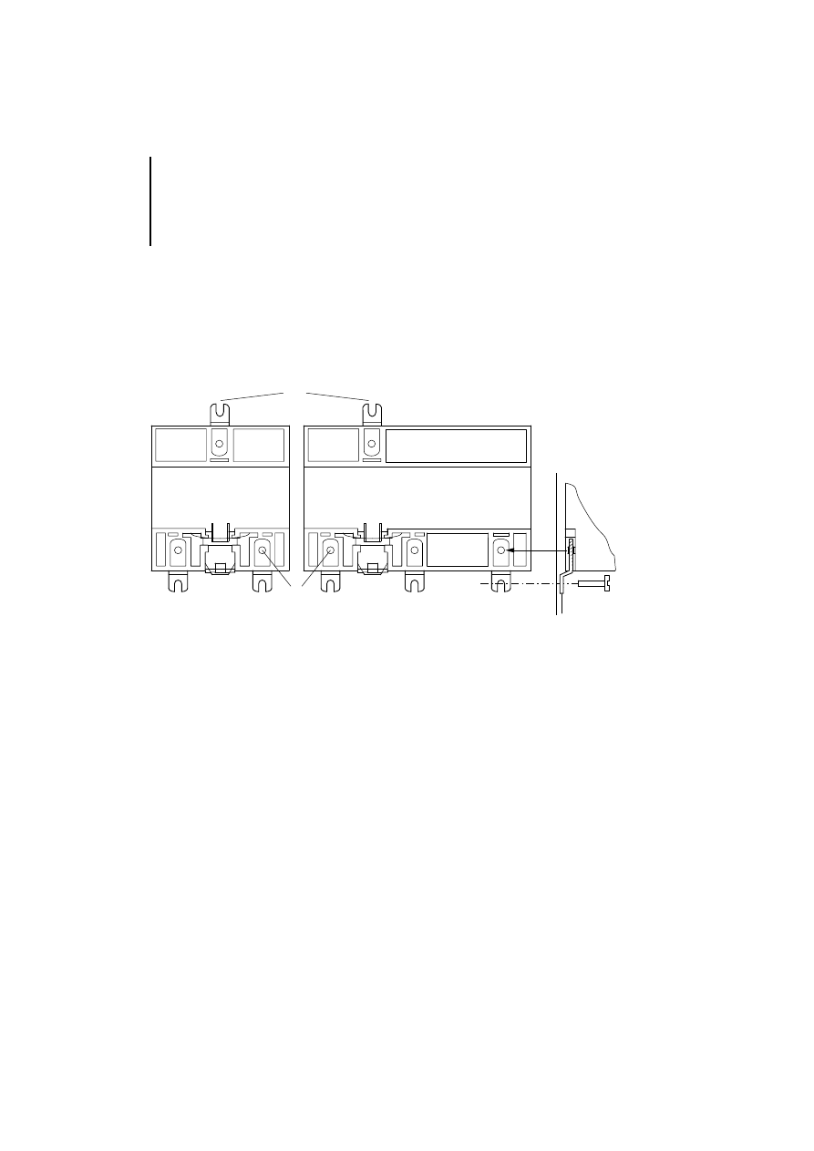
Connection to the PS 4
Connect the LE 4 directly to the PS 4 using the plug
connector.
Figure 15: Connection to the PS 4
29
03/
98 AW
B
2700-
1324 G
B
3
Mounting
Local expansion modules can be mounted either on
the top-hat rail or on fixing feet.
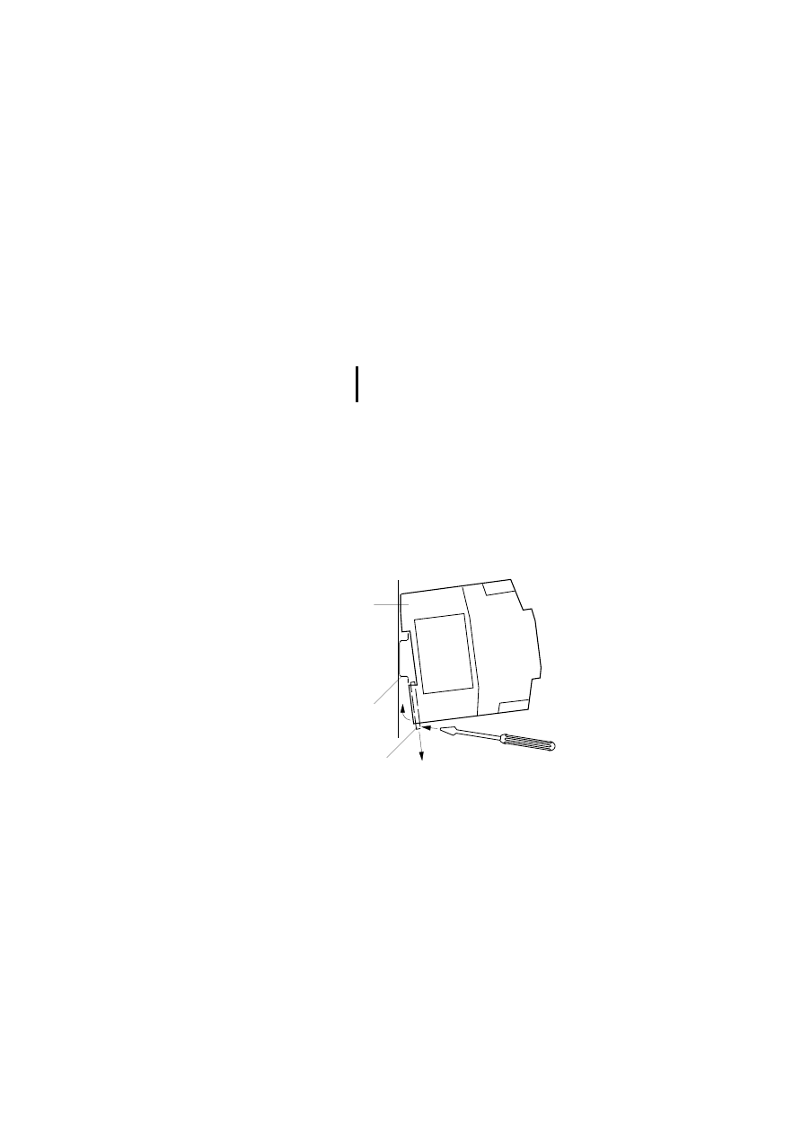
Mounting on the top-
hat rail
왘 Insert one side of the module into the top-hat
rail
햲
.
왘 Use the screwdriver to push the slide bar out of
the module
햳
.
왘 Swivel the module onto the top-hat rail
햴
.
왘 Remove the screwdriver. The slide bar will
engage on the top-hat rail and lock the module in
place
햵
. Check that the module is fixed securely.
Figure 16: Mounting on the top-hat rail
Snap the LE 4 onto the top-hat rail or fix it to the
mounting plate before connecting it to the PS 4.
햲
햳
햴
Mounting
30
03/
98 AW
B
2700-
1324 G
B
Mounting on fixing feet
왘 Push the fixing foot in until it latches into
position
햲
.
왘 Check that it is seated firmly. The latching lug
must engage in the hole
햳
.
왘 Use an M4 screw to fix the fixing feet to the
mounting plate
햴
.
Figure 17: Mounting on fixing feet
햲
PS 4- ....
LE 4-622/633-CX1
햴
햳
햳
Mounting in the switch
cabinet
31
03/
98 AW
B
2700-
1324 G
B
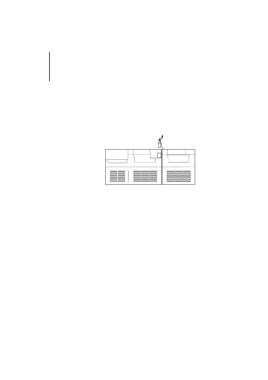
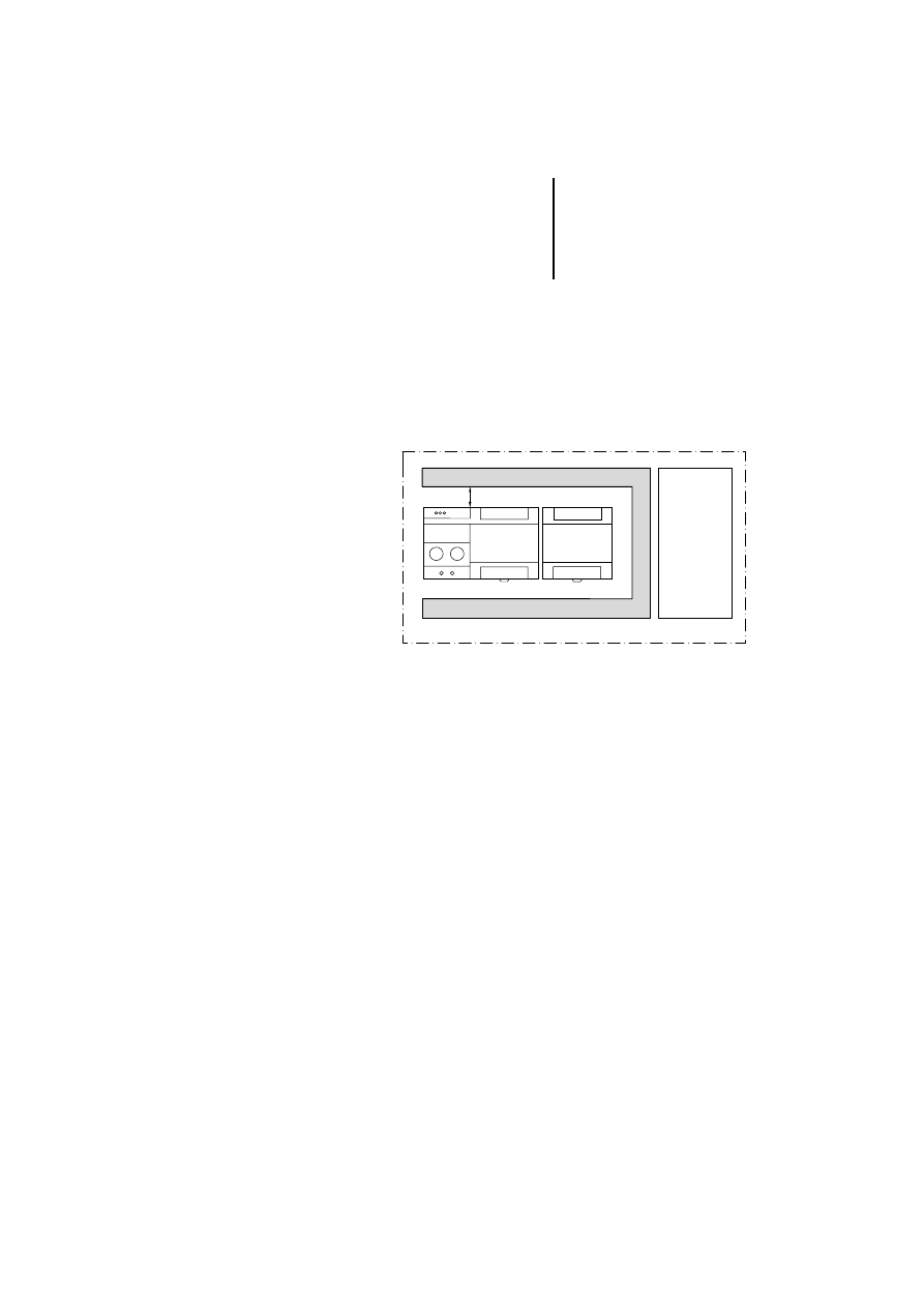
Mounting in the switch
cabinet
The following conditions must be fulfilled:
왘 Fix the PS 4 with its local expansion modules
horizontally in the switch cabinet.
왘 Ensure that it is at least 50 mm away from the
cable duct.
왘 Keep the control and power circuits separate.
Figure 18: Horizontal arrangement of the modules in the
switch cabinet
햲 At least 50 mm
햳 Power circuit
햴 Cable duct
햲
햴
50
햳

32
03/
98 AW
B
2700-
1324 G
B
33
03/
98 AW
B
2700-
1324 G
B
Appendix
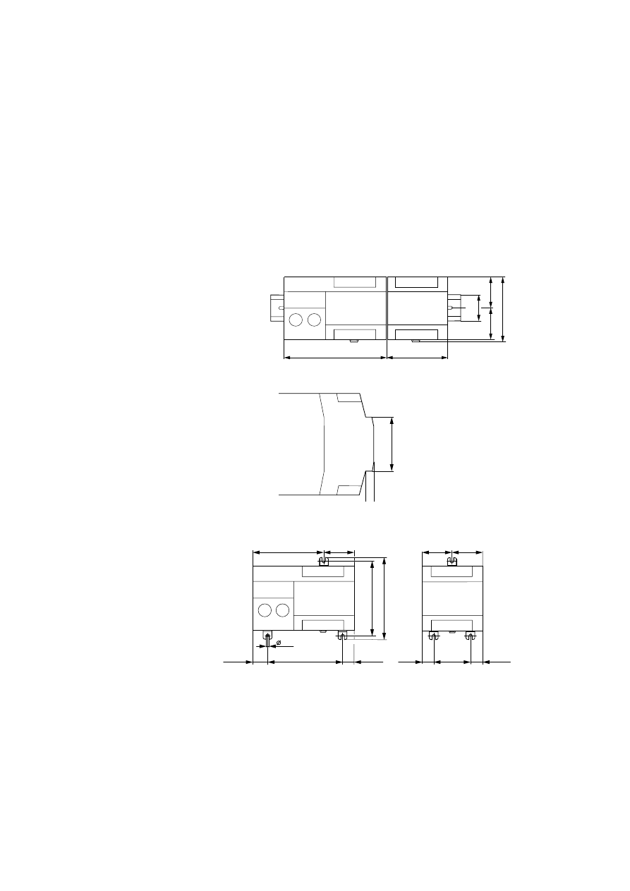
Dimensions
Figure 19: Front view of the PS 4, LE 4
Figure 20: Side view of the PS 4, LE 4
Figure 21: PS 4, LE 4 with fixing feet
42.5
LE 4
35
134.5
80.5
87.5
42.5
PS 4
45
100
110
100
M4
50
LE 4
94.25
40.25
19.25
15.25
40.25
15.25
40.25
15.25
PS 4

Appendix
34
03/
98 AW
B
2700-
1324 G
B
Accessories
Fixing foot
Klöckner-Moeller ZB 4-101-GF1 Fixing foot for screwing the LE or PS 4 onto
a mounting plate
Plug-in screw terminal Klöckner-Moeller ZB 4-110-KL1 Screw terminal for the input/output level
Twin-level terminal
block
Klöckner-Moeller ZB 4-122-KL1 Snap-fit 2 x 11-pole potential terminal
Contact clamps for
fixing the screening
Klöckner-Moeller ZB 4-102-KS1 Contact clamps for connecting the screen of
the data cable to the earth potential
Terminal clamp for
snap-on mounting
e.g. Weidmüller
KLBü 3-8 SC
Order no.:
169226
Snap-on mounting
for the top-hat rail
e.g. Weidmüller
FM 4/TS 35
Order no.:
068790
Lightning protection
module
Module e.g. from
Dehn
–
–

Technical data
35
03/
98 AW
B
2700-
1324 G
B
Technical data
General
Applicable standards
EN 61131-2, EN 50178
Ambient temperature
0 to 55°C
Storage temperature
–25°C to 70°C
Shock
2 shocks with sinusoidal half-wave
11 ms duration, 15 g peak value
Surge withstand capability
15 g, 11 ms
Vibration
Constant 1 g, f = 10 – 150 Hz
EMC
Emissions
EN 55011/22 class A
Immunity to interference
ESD
EN 61 000-4-2
Contact discharge
4 kV
Air discharge
8 kV
RFI
EN 61 000-4-3
AM/PM
10 V/m
Burst
EN 61 000-4-4
Mains/digital I/O
2 kV
analog I/O, field bus
1 kV
Surge
ENV 50 142
Digital I/O, assym.
0.5 kV
Mains DC, assym.
1 kV
Mains DC, sym.
0.5 kV
Mains AC, assym.
2 kV
Mains AC, sym.
1 kV
Line-conducted
interference ENV 50 141
AM
10 V
Degree of protection
IP 20
Humidity class
RH 1
Insulation voltage
600 V AC
Weight
270 g
Connections
Plug-in screw terminals
Conductor cross-sections
flexible with ferrule:
solid:
0.22 to 1.5 mm
2
0.22 to 2.5 mm
2
Power supply to the encoder
Separate via ZB 4-122-KL1 twin-
level terminal block
Data cable to encoder
As per encoder manufacturer’s
specifications (but normally
screened cable)

Appendix
36
03/
98 AW
B
2700-
1324 G
B
LE 4-622-CX1
Phase shift deviation (mode 1+2;
5 V and 24 V incremental encoder)
Max.
50 %
Minimum pulse-width (mode 3;
24 V pulse generator)
16
µ
s
Counter inputs 5 V
Level
Conforming to RS 422
Differential input voltage
U
max
= 5.25 V
U
min
= 2 V
Input current
I
max
= 20 mA at U < 5.25 V
I
min
= 2.5 mA at U > 2 V
Maximum counter frequency
300 kHz
Pulse quadrupling
Yes
90° offset signals
Yes
Antivalent signals
Yes
Counter range
24 bits
Electrical isolation
Yes
Counter inputs 24 V
Input voltage
U
max
= 30 V
U
min
= 18 V
Input current
I
min
= 2.5 mA at U = 18 V
Maximum counter frequency
30 kHz
Pulse quadrupling
Yes (for incremental encoder)
90° offset signals
Yes (for incremental encoder)
Counter range
24 bits
Electrical isolation
Yes

Technical data
37
03/
98 AW
B
2700-
1324 G
B
LE 4-633-CX1
Number of SSI interfaces
3
Data code
Gray or binary (conversion must
be carried out in PS 4)
Data format
Multi-turn 25 bits (13 bits must
be evaluated for single-turn or
21 bit for multi-turn)
Electrical isolation
- LE bus to SSI interfaces
- Between SSI interfaces
Yes
No
Clock output of SSI interface
RS422 electrically isolated, T+,
T–
Data input of SSI interface
RS422 electrically isolated,
D+, D–
Wire break detection
Yes (RS 422, data input D+, D–
only)
Data transmission speed
125 kHz or 250 kHz for all 3 SSI
interfaces
Maximum cable length to absolute
encoder
Depends on the data
transmission speed of the
absolute encoder and is specified
by the manufacturer in the
technical data.
It is limited, however:
Baud rate: cable length:
250 kHz: <150 m
125 kHz: <350 m

38
03/
98 AW
B
2700-
1324 G
B

39
03/
98 AW
B
2700-
1324 G
B
Index
A
Accessories .................................................................... 34
Antivalent signals ........................................................... 14
C
Connection of 24 V incremental encoder ...................... 16
Connection of 5 V incremental encoder ........................ 14
Counter level .................................................................. 19
Counter pulses ............................................................... 19
Counting direction ......................................................... 19
D
Data cable, screening ...................................................... 9
E
EMC ................................................................................. 9
I
Incremental encoder, 24 V ............................................. 16
Incremental encoder, 5 V ............................................... 14
M
Modules
Arrangement in the switch cabinet ............................. 31
Mounting ........................................................................ 29
on the fixing feet ......................................................... 30
on the top-hat rail ....................................................... 29
Mounting in the switch cabinet ...................................... 31
P
Parameter Editor ............................................................ 13
Positiong system
24 V incremental encoder .......................................... 16
Positioning system
5 V incremental encoder ............................................ 14
Q
Quadrupled signals ........................................................ 13

Index
40
03/
98 AW
B
2700-
1324 G
B
R
Reference signal ............................................................. 17
Referenzsignal ................................................................ 15
S
Screening of data cables .................................................. 9
Setup
LE 4-622-CX1 ............................................................... 6
LE 4-633-CX1 ............................................................... 8
Special features
LE 4-622-CX1 ............................................................... 5
LE 4-633-CX1 ............................................................... 7
T
Task
LE 4-622-CX1 ............................................................... 5
LE 4-633-CX1 ............................................................... 7
Technical data ................................................................ 35
Terminal overview
LE 4-622-CX1 ............................................................. 11
LE 4-633-CX1 ............................................................. 12
W
Wire break ...................................................................... 15
Document Outline
- Title
- Safety Instructions
- Contents
- 1 About The Local Expansion Modules
- 2 Engineering
- Electromagnetic compatibility (EMC)
- Overview of the terminals
- Terminal assignment on the data cable
- LE4622-CX1
- Positioning system for 5 V incremental encoders
- In this mode, the LE 4 needs antivalent signals in order to operate.
- :
- Figure 9: Signals from a 24 V incremental encoder
- Fast counter for 24 V pulse generators
- Terminal assignment for the SSI data cable on the LE4633CX1
- .
- Figure 12: Multi-turn data format (25-bit) for synchronous serial data transmission with bit patt...
- Figure 13: Multi-turn data format (21-bit) for synchronous serial data transmission with bit patt...
- Please also note the data format information provided by the absolute encoder manufacturer.
- Number of LEs per PS4
- Connection to the PS4
- 3 Mounting
Wyszukiwarka
Podobne podstrony:
PS4 LE 4 504 BS1, Master h1368g
PS4 LE 4 206 AA2 h1331g
h1239g PLC PS4 416
+le%9cmian+boles%b3aw+ +wiersze+wybrane 52RWPQJSPV3GXGTUE7QA4446RJVPT2XSKPEIAXY
Mentalność-Le Goff, Materiały
Drgania i?le TEST B
Sylabus LE
Zadania ?le
Drgania i?le sprężyste praca klasowa
FIZYKA ?LE
Akumulator do DUTRA LE ROBUSTE D 4 KB D 4 KB
5 ?le (17 03)
Wykład 1 ?finicje,?le, zadania psychologii
Pio XII Le vicaire de hochhuth et le vrai Pie XII
Agamben, Giorgio Le cinéma de Guy Debord
Le Goff Sakiewka i życie
więcej podobnych podstron