
Service Source
K
Power Macintosh 8100/
WS 8150
Power Macintosh 8100/80 and 8100/80AV, Power
Macintosh 8100/100 and 8100/100AV, Power
Macintosh 8100/110, Workgroup Server 8150,
Workgroup Server 8150/110

Service Source
K
Basics
Power Macintosh 8100/WS 8150

Basics
Power Macintosh System Overview - 1
Power Macintosh System Overview
PowerPC microprocessors are a family of processors built
on reduced instruction-set computing (RISC) technology.
RISC processors streamline the internal workings of
computers. Whereas traditional (complex instruction-set
computing, or CISC) processors contain a wide variety of
instructions to handle many different tasks, RISC
processors contain only those instructions that are used
most often. When a complex instruction is needed, a RISC
processor builds it from a combination of basic instructions.
RISC processors are designed to execute these basic
instructions extremely quickly. The performance gains
achieved by speeding up the most-used instructions more
than compensate for the time spent creating less-used
instructions.

Basics
Power Macintosh System Overview - 2
Previously, RISC technology had been used only in high-end
workstations and commercial database servers. With the
introduction of Macintosh PowerPC computers, Apple
succeeded in bringing RISC technology to personal
computing.
Key Points
Three key points to remember about a PowerPC processor-
based Macintosh system: It's a Macintosh; it's compatible; it
offers tremendous performance.
Apple's PowerPC computers feature the same user interface
as their 680x0-based predecessors. Users can mix RISC-
based and 680x0-based Macintosh systems on the same net-
work and exchange files and disks between them. In addition,
users can run both 680x0 and native PowerPC applications
on the same Power Macintosh system simultaneously.

Basics
Power Macintosh System Overview - 3
Compatibility is not limited just to applications. INITs,
CDEVs, drivers, and other Macintosh utility software also
work on PowerPC processor-based Macintosh systems. So do
AppleTalk devices (such as printers), SCSI devices (such as
hard drives and scanners), ADB devices (such as mice,
trackballs, and keyboards), and other Macintosh cards and
peripherals.
The primary operating system for PowerPC processor-
based Macintosh computers is System 7. The operating
system has been optimized for the highest performance on
the PowerPC processor. This optimization of System 7
benefits applications written for 680x0 systems as well as
those developed specifically for PowerPC processor-based
systems.
And while PowerPC-based Macintosh systems running
native applications offer two to four times the performance

Basics
Power Macintosh System Overview - 4
of the fastest 68040- and 80486-based personal
computers, the real promise of PowerPC technology is that
it enables Apple and other developers to deliver new
software capabilities on Macintosh systems that were
previously available only on high-end workstations.
Troubleshooting Tips
When troubleshooting Power Macintosh systems, keep in
mind the following:
1 If a Power Macintosh system does not power up, you
should first attempt to reset the logic board. Instruc-
tions are provided in the Additional Procedures chapter.
2 With Power Macintosh computers, you must install
noncomposite RAM SIMMs only, and the RAM SIMMs
must be installed in like pairs (that is, the same size and
speed). Additional troubleshooting information is

Basics
Power Macintosh System Overview - 5
provided in the Symptom Charts section of the
Troubleshooting chapter under the “System” topic
heading.
3 If a Power Macintosh system has bad RAM SIMMs
installed, you will not hear death chimes. Instead, a
dialog box will appear alerting you to the fact that a bad
RAM SIMM has been detected. Additional troubleshooting
information is provided in the Symptom Charts section
of the Troubleshooting chapter under the “System” topic
heading.
4 If the system hangs shortly after installing a new NuBus
card, contact the vendor to verify that the card is
compatible with the Power Macintosh system or to see if
there is a software upgrade available. If the NuBus card
is an Apple manufactured product, refer to the Service
Tech Info Library for more information.

Basics
Power Macintosh System Overview - 6
5 The Power Macintosh AV systems use the same logic
board as the non-AV versions. The only difference is that
the AV versions have the Power Macintosh AV Card
installed in the PDS slot.
The Power Macintosh 7100/66 and 8100/80 systems
must
have a video card installed in the PDS slot. The
Power Macintosh 7100/66 system uses the Power
Macintosh 2 MB Video Card and the Power Macintosh
8100/80 system uses the Power Macintosh 4 MB Video
Card. A missing card can result in a system that won't
boot or a system that crashes.
Basics
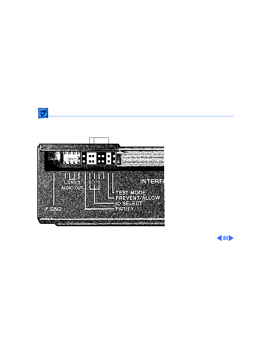
HDI-45 Pinouts - 7
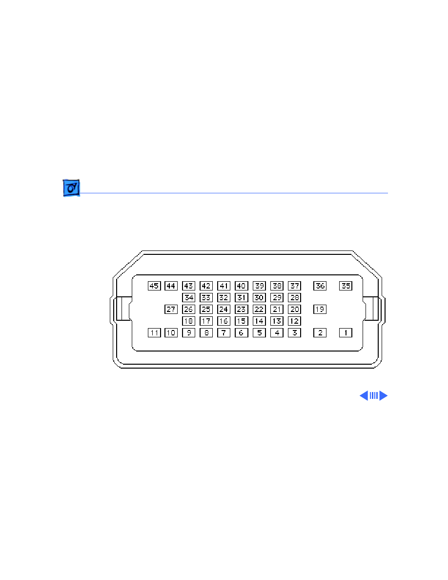
HDI-45 Pinouts
This section includes an illustration of the HDI-45
connector and a table containing the pinout descriptions.
Figure: HDI-45 Connector on the Logic Board
Basics
HDI-45 Pinouts - 8
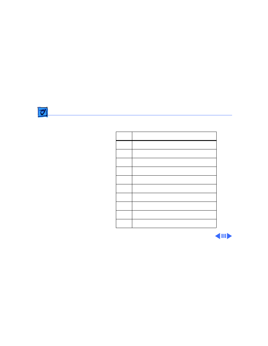
Table: HDI-45 Pinouts
Pin
Description
1
Analog audio ground
2
Audio input shield
3
Left channel audio input
4
Right channel audio input
5
Left channel audio output
6
Right channel audio output
7
Reserved
8
Monitor ID sense line 1
9
Monitor ID sense line 2
10
Green ground (shield)

Basics
HDI-45 Pinouts - 9
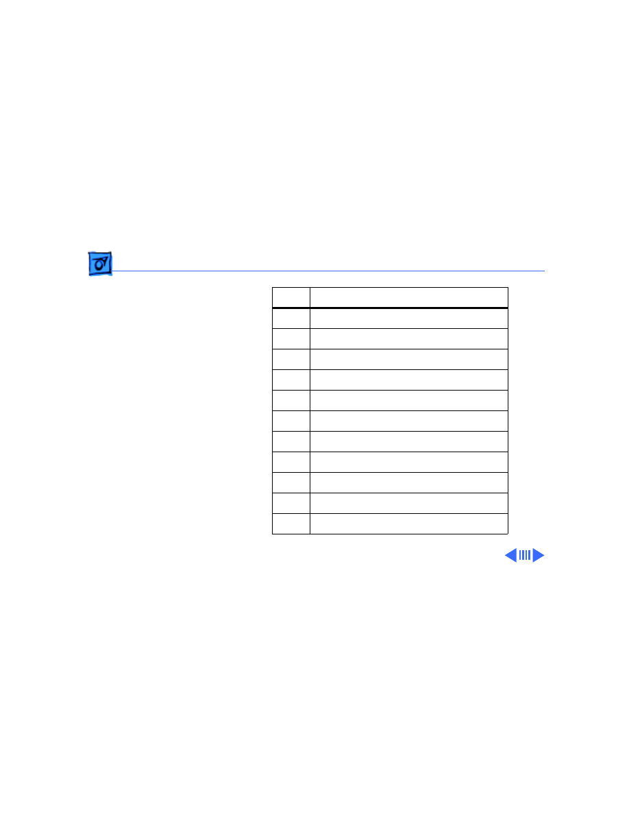
11
Green video output (75Ω)
12
Video input power ground
13
Power for camera +5 V
14
Reserved
15
Reserved
16
Reserved
17
Reserved
18
Monitor ID sense line 3
19
S-video input shield
20
S-video input luminance (Y)
21
S-video input chroma (C)
Pin
Description

Basics
HDI-45 Pinouts - 10
22
Reserved
23
Reserved
24
Reserved
25
Reserved
26
Red ground (shield)
27
Red video output (75Ω)
28
I
2
C data signal
29
I
2
C clock signal
30
Reserved
31
Monitor ID
32
Monitor ID
Pin
Description
Basics
HDI-45 Pinouts - 11
33
Vertical sync signal
34
Composite sync signal
35
ADB power +5 V
36
ADB ground
37
ADB data
38
Keyboard switch
39
Reserved
40
Reserved
41
Monitor ID
42
Horizontal sync signal
43
Video sync ground
Pin
Description
Basics
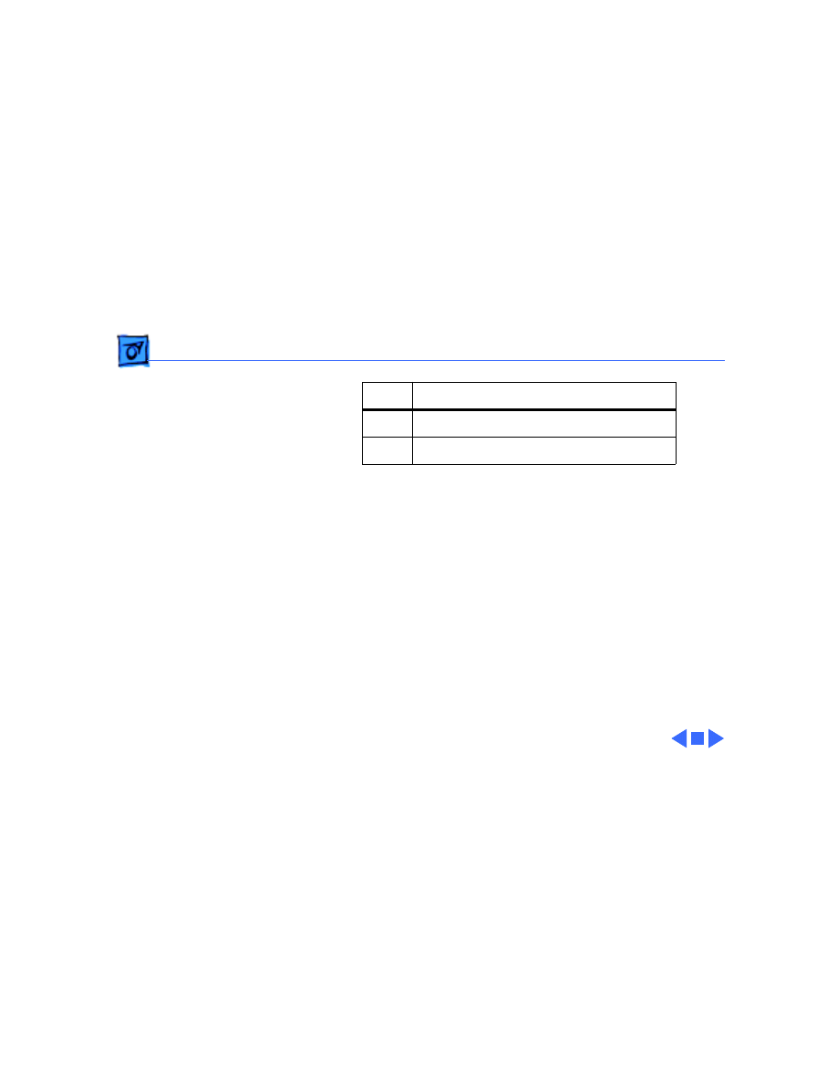
HDI-45 Pinouts - 12
44
Blue ground (shield)
45
Blue video output (75Ω)
Pin
Description

Basics
Rear Panel Connectors - 13
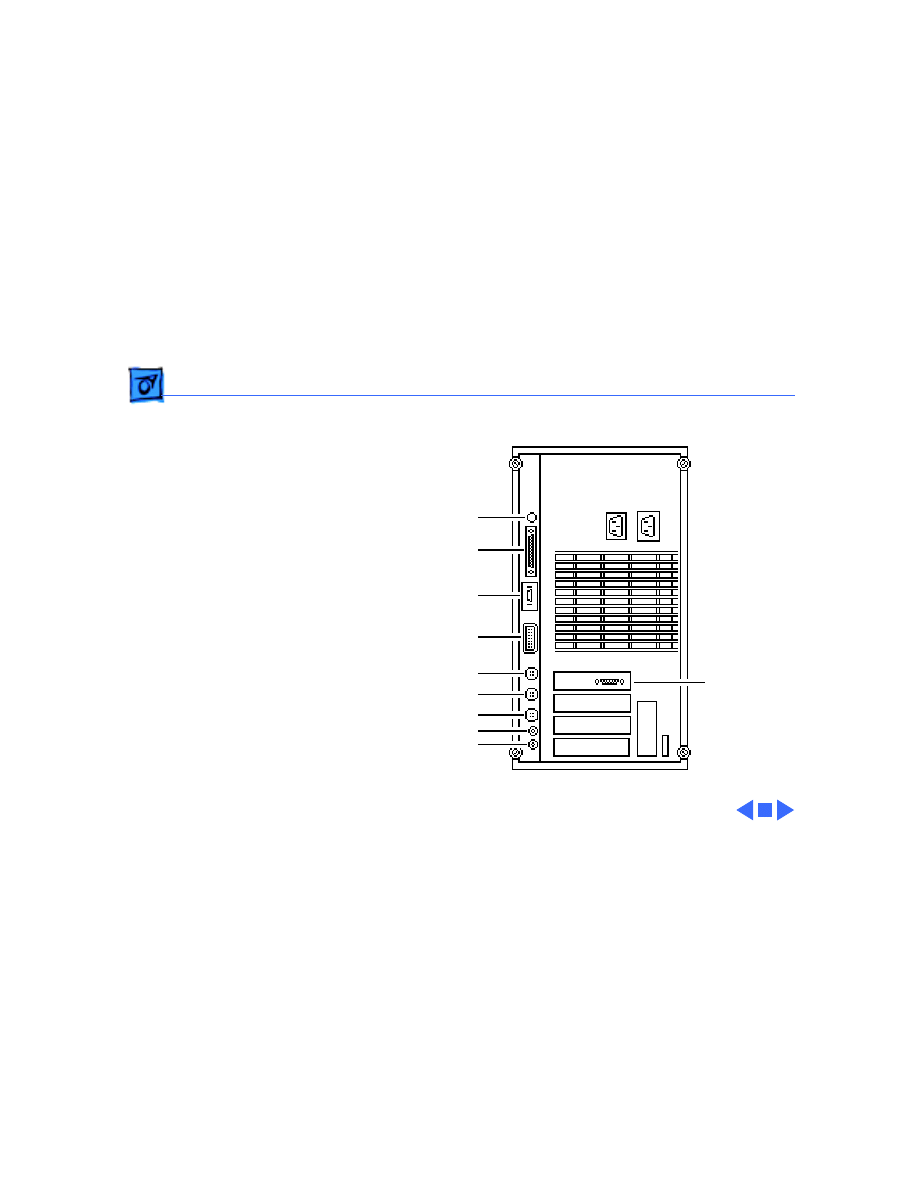
Rear Panel Connectors
The figure on the following page shows a Power Macintosh
8100 computer with a 4 MB Video Card installed. The AV
version of the Power Macintosh 8100 would have a Power
Macintosh AV Card installed instead of the 4 MB Video Card.
In addition to a DB-15 connector, the AV Card includes an S-
Video Input and an S-Video Output port.
Basics
Rear Panel Connectors - 14
Power Macintosh 8100 Rear Panel
Power-On
SCSI
Ethernet
HDI-45 Video
Printer
Modem
ADB
Sound Out
Sound In
DB-15

Basics
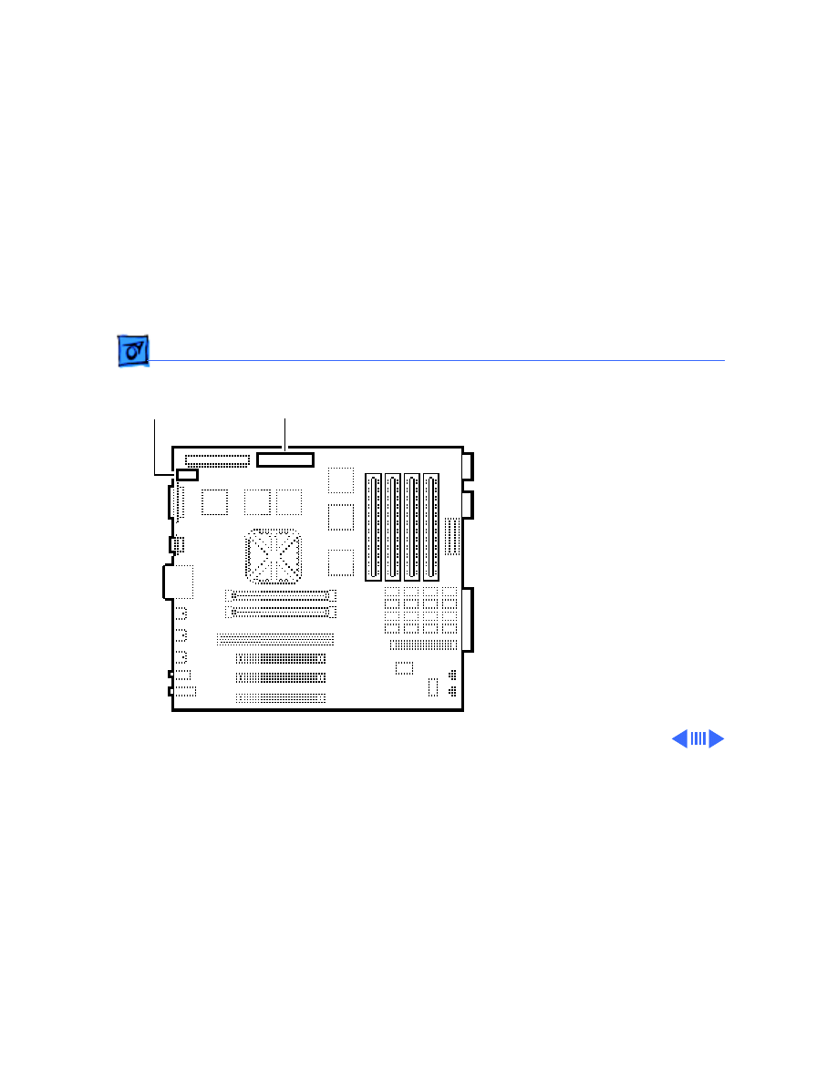
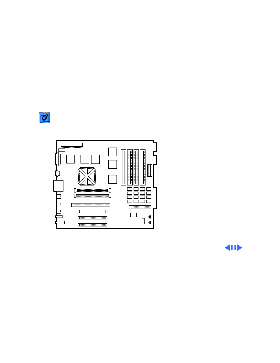
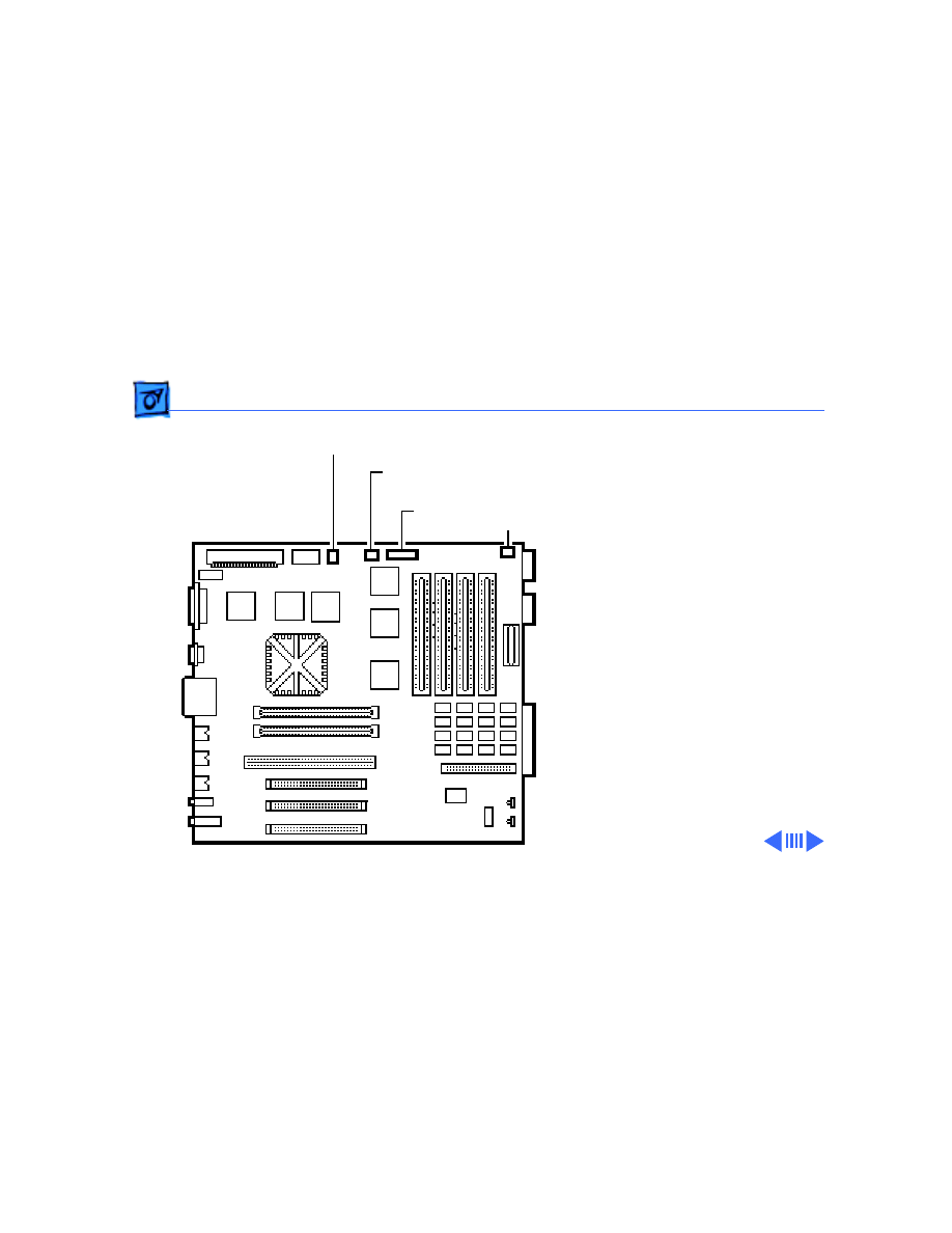
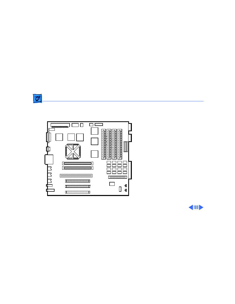
Logic Board Connectors - 15
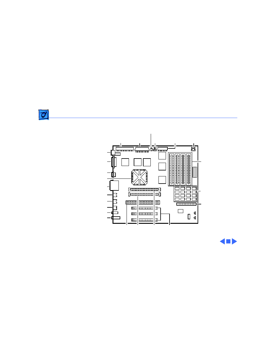
Logic Board Connectors
The figure on the following page shows a Power Macintosh
8100/80 logic board.
Caution
: It is important to note that the Power Macintosh
8100/100 and 8100/110 Series logic boards have a
thermoelectrical cooling device that attaches directly to the
microprocessor’s heatsink. You can identify this cooling
device by the black and red wires that run to the right of the
heatsink and plug into the logic board via a keyed connector.
This device is not a serviceable item. Do
not
unplug this
device or you may damage the logic board.
Basics
- 16
Speaker
CD-ROM
Audio
Floppy
Drive
LED
DRAM SIMMs
8 MB Soldered
DRAM
Hard Drive
SCSI
NuBus
Slots
L2 Cache
Slot
ROM
Slot
601
PDS
Sound In
Sound Out
ADB
Modem
Printer
HDI-45 Video
PowerPC 601 Chip
Ethernet
SCSI
Power On
CD-ROM/
Tape SCSI
Power
Supply

Basics
Apple RAID Software - 17
Apple RAID Software
Apple RAID (Redundant Array of Independent Disks)
software protects data from loss during a disk failure and
enhances the speed of data storage and retrieval. It is
available for all Power Macintosh Workgroup servers.
Data protection is achieved through disk mirroring, a data
storage scheme in which identical data is stored on two
different disks. Apple RAID can also be configured for disk
striping, a data storage scheme in which successive units of
data are transferred to several disks at one time.
If you plan to install the Apple RAID software on an existing
Power Macintosh Workgroup Server, or if you are
reinitializing an existing Apple RAID drive, keep in the mind
the following:

Basics
Apple RAID Software - 18
• If you wish to use your server's startup disk for Apple
RAID, do not install the Apple RAID program on your
startup disk until you have initialized and set up new
volumes on that disk. Before you initialize the startup
disk, back up all valuable data.
• You must reinitialize all disks on which you will use
Apple RAID volumes. Initializing with Apple RAID
removes all data, so be sure to back up your disks first.
• Apple HD SC Setup does not recognize Apple RAID
volumes. If you want to remove or resize volumes on
Apple RAID disks, use the Apple RAID program.
• The Apple RAID CD contains the facilities to reinstall
your system software. However, if you have made any
customizations to your system files, such as adding
extension files, control panels, or preference files, then

Basics
Apple RAID Software - 19
back up your system files now. Back them up in such a
way that you can restore your system files separately
from the nonsystem files on your disk. You will later
restore your system files using the backup copy rather
than the System Installer on the RAID CD, so that you
preserve your system customizations.
Service Source
K
Specifications
Power Macintosh 8100/WS 8150

Specifications
Processor - 1
Processor
CPU
Built-in MMU and FPU
32K of on-chip cache memory
80, 100 or 110 MHz PowerPC 601 RISC microprocessor
8100/80 & 8150
Requires system software version 7.1.2 or later
8100/100, 8100/110 &
8150/110
Requires system software version 7.5 or later
Note
: To run System 7.5 on these systems, you need enabler
version 1.1.1 at a minimum. This version of the system
software requires Finder version 7.1.5. You can verify the
Finder version installed by using the "Get Info" command.
Refer to the Tech Info Library for more information.

Specifications
Memory - 2
Memory
RAM
8100/80, 8100/100 &
8150
8 MB RAM soldered on logic board, expandable to 264 MB via 8
SIMM sockets on logic board (using pairs of same size, 80 ns
or faster, 72-pin noncomposite SIMMs); Optional 16 MB
configuration has two 4 MB SIMMs installed
8100/110 & 8150/110
16 MB RAM standard (8 MB soldered on logic board and two 4 MB
SIMMs), expandable to 264 MB via 8 SIMM sockets on logic
board (using pairs of same size, 80 ns or faster, 72-pin
noncomposite SIMMs)
Note
: SIMMs must be installed in pairs of the same size. Install
noncomposite SIMMS only.

Specifications
Memory - 3
VRAM
8100/80, 8100/100,
8100/110, 8150 &
8150/110
2 MB of VRAM on video card, expandable to 4 MB using 512K
VRAM SIMMs
8100/80AV & 8100/
100AV
2 MB of VRAM on Macintosh AV card, including support for NTSC
or PAL monitors
8150 & 8150/110
None
ROM
4 MB installed on ROM SIMM
Cache
32K on-chip cache; 256K level 2 cache SIMM
Clock/Calendar
CMOS custom chip with long-life lithium battery

Specifications
Disk Storage - 4
Disk Storage
Hard Drive
8100/80
500 MB or 1 GB hard drive
8150
500 MB, 1 GB, or 2 GB hard drive
8100/100
700 MB or 1 GB hard drive
8100/110
2 GB hard drive
8150/110
1 GB hard drive
Floppy Drive
1.4 MB Apple SuperDrive Manual Insert

Specifications
Disk Storage - 5
CD-ROM Drive
Internal AppleCD 300 Plus CD-ROM drive optional on some
models and standard on other models
8150/110
AppleCD 600 CD-ROM drive standard

Specifications
I/O Interfaces - 6
I/O Interfaces
SCSI
One SCSI port; DB-25 connector
Supports maximum of six external devices (five with CD-ROM
drive)
Serial
Two RS-232/RS-422 LocalTalk/GeoPort serial ports; mini DIN-
9 connectors (backward compatible with mini DIN-8
connectors)
Apple Desktop Bus
One Apple Desktop Bus (ADB) port; mini-Din-4 connector
Maximum power draw 500 mA; maximum of three devices total
Ethernet
One Ethernet port; AAUI-15 connector

Specifications
I/O Interfaces - 7
Expansion Slot
One processor-direct slot (PDS); 182-pin connector
NuBus
Three slots support long or short expansion cards; 96-pin Euro-
DIN connectors
Sound
16-bit stereo in and out
Sample rates of 48, 44.1, 24, and 22.05 kHz
Input/output line level: 1 V peak-to-peak
Input/output signal-to-noise ratio (SNR): 82 dB with no audible
discrete tones
Bandwidth: 20 Hz–20 kHz (± 2 dB) at 44.100 kHz sample rate
THD+N (total harmonic distortion plus noise): less than 0.05%,
measured 20Hz–20kHz with a 1-Vrms sine wave input

Specifications
I/O Interfaces - 8
Video
One HDI-45 DRAM-based video port on logic board supports
direct connection to Apple AudioVision monitors and with
optional HDI-45 to DB-15 adapter supports 12-in., 13-in.,
14-in., 15-in. portrait, 16-in., and 17-in. monitors
8100/80, 8100/100,
8100/110
Come with a Power Macintosh 4 MB Video Card with one DB-15
VRAM-based video port that supports 12-in., 13-in., 14-in.,
15-in. portrait, 16-in., 17-in., 20-in., and 21-in. monitors
8100/80AV & 8100/
100AV
Come with a Power Macintosh AV Card* with: one DB-15 VRAM-
based video on the card that supports 12-in., 13-in., 14-in.,
15-in. portrait,16-in., 17-in., 20-in., and 21-in.
monitors; one S-video/composite input port; and one S-video
composite output port
*Only one monitor can be attached to the card at one time (that
is, either through the DB-15 port or the S-video port).

Specifications
I/O Interfaces - 9
Digital-Audio Video
8100/80AV & 8100/
100AV
Support for DAV connector standard
Ê

Specifications
I/O Devices - 10
I/O Devices
Keyboard
Standard, extended, or adjustable keyboard
Keyboard draws 25–80 mA, depending on model of keyboard
Mouse
ADB Mouse II; Draws up to 10 mA
Microphone
8100/80, 8150 & 8150/
110
Optional Apple PlainTalk microphone; unidirectional and
optimized for use with speech recognition
8100/80AV, 8100/100,
8100/100AV & 8100/
110
Apple PlainTalk microphone standard

Specifications
Video Display - 11
Video Display
Video Support
System must have the Power Macintosh 4 MB Video Card, Power
Macintosh AV Card, or PDS terminator board installed.
These systems support monochrome, color, VGA, and SVGA formats
on the HDI-45 logic board connector, including:
• Macintosh 12" Monochrome Display (640 x 480)
• Macintosh 12" RGB Display (512 x 384)
• AppleColor High-Res RGB 14" Monitor (640 x 480)
• Apple AudioVision 14 Display (640 x 480)
• Macintosh Color Display (640 x 480)
• Macintosh 15" Portrait Display (640 x 870)
• Macintosh 16" Color Display (832 x 624)
Ê

Specifications
Video Display - 12
Video Support
(cont’d)
All Power Macintosh 8100 series computers support the
following monitors via the DB-15 connector on their
respective video cards:
• Macintosh 19" Color Display (1024 x 768)
• Apple Multiple Scan 20 Display (1280 x 1024)
• Macintosh 21" Color Display (1152 x 870)
In addition, the AV versions support the following monitors via the
DB-15 connector on the Power Macintosh AV Card:
• NTSC (512 x 384 and 640 x 480)
• PAL (640 x 480 and 768 x 576)

Specifications
Electrical - 13
Electrical
A/C Line Input
Voltage
100–240 VAC; RMS single phase, automatically configured
Input Line
Frequency
50–60 Hz, single phase
Input Power
298 W maximum continuous, 453 W peak input (not including
monitor power)
Power Supply DC
Output
200 W continuous output

Specifications
Physical - 14
Physical
Dimensions
Height: 14.25 in. (360 mm)
Width: 7.75 in. (196 mm)
Depth: 16 in. (396 mm)
Weight
25.3 lb. (11.5 kg); weight varies depending on internal devices
installed

Specifications
Environmental - 15
Environmental
Operating
Temperature
50–104° F (10° to 40° C)
Storage
Temperature
–40 to 116.6° F (–40 to 47° C)
Relative Humidity
5–90% noncondensing
Altitude
0–3048 m (0–10,000 ft.)
Service Source
K
Troubleshooting
Power Macintosh 8100/WS 8150

Troubleshooting
General/ - 1
General
The Symptom Charts included in this chapter will help you
diagnose specific symptoms related to your product. Because cures
are listed on the charts in the order of most likely solution, try
the first cure first. Verify whether or not the product continues to
exhibit the symptom. If the symptom persists, try the next cure.
(Note: If you have replaced a module, reinstall the original module
before you proceed to the next cure.)
If you are not sure what the problem is, or if the Symptom Charts
do not resolve the problem, refer to the Flowchart for the product
family.
For additional assistance, contact Apple Technical Support.

Troubleshooting
Symptom Charts/Power Supply - 2
Symptom Charts
Power Supply
System does not
power up
1 Reset logic board. (Refer to Additional Procedures.)
2 Reseat ROM SIMM and cache SIMM.
3 Replace power supply.
4 Replace logic board.

Troubleshooting
Symptom Charts/Error Chords - 3
Error Chords
One-part error
chord sounds during
startup sequence
1 Disconnect SCSI data cable from hard drive and reboot
system. If startup sequence is normal, initialize hard drive.
If error chord still sounds, replace hard drive.
2 Disconnect floppy drive cable from floppy drive and reboot
system. If startup sequence is normal, replace floppy drive.
3 Replace logic board. Retain customer’s SIMMs.

Troubleshooting
Symptom Charts/System - 4
System
Does not power on;
screen is black, fan is
not running, and LED
is not lit
1 Check power cables.
2 Plug monitor directly into wall socket, and verify that
monitor has power.
3 Reset logic board. (Refer to Additional Procedures.)
4 Reseat ROM SIMM and cache SIMM.
5 Replace power cord.
6 Replace power supply.
7 Replace logic board. Retain customer’s SIMMs.
Clicking, chirping,
or thumping
1 Replace power supply.
2 Replace logic board. Retain customer’s SIMMs.
3 Replace floppy drive cable.
4 Replace floppy drive.
Ê

Troubleshooting
Symptom Charts/System
(Continued)
- 5
System
(Continued)
System shuts down
intermittently
1 Make sure air vents are clear. Thermal protection circuitry
may shut down system. After 30 to 40 minutes, system
should be OK.
2 Replace power cord.
3 Check battery. Refer to “Battery Verification” in Additional
Procedures.
4 Replace power supply.
5 Replace logic board. Retain customer’s SIMMs.

Troubleshooting
Symptom Charts/System
(Continued)
- 6
System
(Continued)
System
intermittently
crashes or hangs
1 Verify system software is version 7.1.2 or later.
2 Verify SIMMs are installed in pairs of same size/speed and
are noncomposite.
3 Verify software is known-good.
4 Verify software is Power Macintosh compatible (contact
developer).
5 Verify PDS slot has video card installed.
6 Clear parameter RAM. Hold down <Command> <Option> <P>
<R> during startup but before “Welcome to Macintosh”
appears.
7 Replace SIMMs.
8 Replace cache SIMM.
9 Replace logic board. Retain SIMMs.
10 Replace power supply.

Troubleshooting
Symptom Charts/System
(Continued)
- 7
System
(Continued)
During startup,
following message is
displayed, “This
startup disk will not
work on this
Macintosh model.”
1 Verify that startup disk is good.
2 Verify that LED cable is securely attached to logic board.
3 Reinstall system software.
4 Replace LED cable.
5 Replace logic board. Retain customer’s SIMMs.

Troubleshooting
Symptom Charts/Video - 8
Video
Screen is black, audio
and drive operate, fan
is running, and LED is
lit
1 Adjust brightness on monitor.
2 Replace video cable.
3 Try using known-good RAM SIMMs.
4 Replace video card.
5 Clear parameter RAM. Hold down <Command> <Option> <P>
<R> during startup but before “Welcome to Macintosh”
appears.
6 Replace SIMMs.
7 Replace monitor. Refer to appropriate monitor manual to
troubleshoot defective monitor.
8 Replace logic board. Retain customer’s SIMMs.
9 Replace power supply.

Troubleshooting
Symptom Charts/Video
(Continued)
- 9
Video
(Continued)
Screen is black, audio
and drive do not
operate, but fan is
running and LED is lit
1 Replace video cable.
2 Replace video card.
3 Replace SIMMs.
4 Replace logic board. Retain customer’s SIMMs.
5 Replace power supply.
Partial or whole
screen is bright and
audio is present, but
no video information
is visible
1 Replace video cable.
2 Replace video card.
3 Clear parameter RAM. Hold down <Command> <Option> <P>
<R> during startup but before “Welcome to Macintosh”
appears.
4 Replace monitor. Refer to appropriate monitor manual to
troubleshoot defective monitor.
5 Replace logic board. Retain customer’s SIMMs.

Troubleshooting
Symptom Charts/Video
(Continued)
- 10
Video
(Continued)
Multiple Scan
monitor attached to
Power Macintosh
8100/80AV displays
ghosting or video
smearing
1 Replace Power Macintosh AV Card.

Troubleshooting
Symptom Charts/Floppy Drive - 11
Floppy Drive
Internal floppy drive
does not operate
1 Replace disk with known-good floppy disk.
2 Replace floppy drive cable.
3 Replace floppy drive.
4 Replace logic board. Retain customer’s SIMMs.
5 Replace power supply.
During system
startup, disk ejects;
display shows icon
with blinking “X”
1 Replace disk with known-good system disk.
2 Clear parameter RAM. Hold down <Command> <Option> <P>
<R> during startup but before “Welcome to Macintosh”
appears.
3 Replace floppy drive cable.
4 Replace floppy drive.
5 Replace logic board. Retain customer’s SIMMs.

Troubleshooting
Symptom Charts/Floppy Drive
(Continued)
- 12
Floppy Drive
(Continued)
Does not eject disk
1 Switch off computer. Hold mouse button down while you
switch computer on.
2 Replace floppy drive cable.
3 Replace floppy drive.
4 Replace logic board. Retain customer’s SIMMs.
Attempts to eject
disk, but doesn’t
1 Push disk completely in.
2 Reseat floppy drive bezel and drive so bezel slot aligns
correctly with drive.
3 Eject disk manually.
4 Replace floppy drive.
Internal floppy drive
runs continuously
1 Replace disk with known-good floppy disk.
2 Replace floppy drive cable.
3 Replace floppy drive.
4 Replace logic board. Retain customer’s SIMMs.

Troubleshooting
Symptom Charts/Floppy Drive
(Continued)
- 13
Floppy Drive
(Continued)
MS-DOS drive does
not recognize a disk
formatted on a 1.4 MB
drive
1 To read and write files with either MS-DOS or 1.4 MB drive,
format all disks with MS-DOS drive first.

Troubleshooting
Symptom Charts/Hard Drive - 14
Hard Drive
Single internal hard
drive does not
operate; drive
doesn’t spin
1 Check the SCSI and hard drive power cable connections.
2 Replace hard drive power cable.
3 Replace hard drive. (Note: If replacing an Apple WS 8150
RAID drive, you must reinstall the RAID software on the
drive. See “RAID Information” in Basics.)
4 Replace power supply.
No internal SCSI
drives operate
1 Verify there are no duplicate SCSI device addresses.
2 Replace SCSI data cable.
3 Replace power supply.
4 Replace logic board. Retain customer’s SIMMs.

Troubleshooting
Symptom Charts/Hard Drive
(Continued)
- 15
Hard Drive
(Continued)
Drive does not appear
on the desktop
1 Verify there are no duplicate SCSI device addresses.
2 Update the SCSI device driver using Apple HD SC Setup. Run
Disk First Aid to verify the condition of the drive’s
directory structure.
3 Replace the SCSI hard drive cable.
4 If drive is not initialized, use HD SC Setup to initialize.
(Note: Use Apple RAID to initialize RAID drives for the WS
8150 drives.)
5 Replace with known-good hard drive. (Note: If replacing an
Apple WS 8150 RAID drive, you must reinstall the RAID
software on the drive. See “RAID Information” in Basics.)
6 If the hard drive still doesn’t work, switch back to the
original hard drive and replace the logic board.

Troubleshooting
Symptom Charts/Hard Drive
(Continued)
- 16
Hard Drive
(Continued)
Works with internal
or external SCSI
devices but not with
both
1 Verify there are no duplicate SCSI device addresses.
2 Replace terminator on external SCSI device.
3 Verify that SCSI device at end of internal SCSI data cable is
only device terminated.
4 Refer to appropriate manual to troubleshoot defective
external device.

Troubleshooting
Symptom Charts/Peripherals - 17
Peripherals
Cursor does not move
1 Replace external SCSI cables.
2 Verify that there is only one terminator on external devices.
3 Check mouse connection.
4 Inspect inside of mouse for buildup of dirt or other
contaminants. Clean mouse if necessary.
5 If mouse was connected to keyboard, connect mouse to
computer ADB port instead. If mouse works, replace
keyboard.
6 If mouse does not work in any ADB port on computer, replace
mouse.
7 Replace logic board. Retain customer’s SIMMs.

Troubleshooting
Symptom Charts/Peripherals
(Continued)
- 18
Peripherals
(Continued)
Cursor moves, but
clicking mouse
button has no effect
1 Replace mouse.
2 Replace logic board. Retain customer’s SIMMs.
Double-click doesn’t
open application,
disk, or server
1 Remove duplicate system folders.
2 Clear parameter RAM. Hold down <Command> <Option> <P>
<R> during startup but before “Welcome to Macintosh”
appears.
3 If mouse was connected to keyboard, connect mouse to
computer ADB port instead. If mouse works, replace
keyboard.
4 If mouse does not work in any ADB port on computer, replace
mouse.
5 Replace logic board. Retain customer’s SIMMs.

Troubleshooting
Symptom Charts/Peripherals
(Continued)
- 19
Peripherals
(Continued)
No response to any
key on keyboard
1 Check keyboard connection to ADB port.
2 Replace keyboard cable.
3 Replace keyboard.
4 Replace logic board. Retain customer’s SIMMs.
Known-good serial
printer does not work
1 Verify you have correct version of system software (see
Processor topic in Specifications chapter).
2 Verify that Chooser is set correctly.
3 Replace printer interface cable.
4 Replace logic board. Retain customer’s SIMMs.
Known-good network
printer does not print
1 Verify you have correct version of system software (see
“Processor” topic in Specifications chapter).
2 Verify that Chooser is set correctly.
3 Replace logic board. Retain customer’s SIMMs.

Troubleshooting
Symptom Charts/Miscellaneous - 20
Miscellaneous
No sound from
speaker
1 Verify that volume setting in Control Panel is 1 or above.
2 Replace speaker.
3 Replace logic board. Retain customer’s SIMMs.
About This Macintosh
reports more memory
than is installed
1 Verify that RAM SIMMs are installed in matching pairs
(same size and speed).
2 Replace RAM SIMMs.Ê
About This Macintosh
reports less memory
than is installed
1 Verify that RAM SIMMs are installed in matching pairs
(same size and speed).
2 Replace RAM SIMMs.

Troubleshooting
Symptom Charts/CD-ROM Drive - 21
CD-ROM Drive
CD-ROM drive does
not accept compact
disc
1 Exchange disc.
2 Replace CD-ROM drive mechanism.
Macintosh does not
display CD-ROM
drive icon
1 Verify that CD-ROM software is installed.
2 Replace CD-ROM drive mechanism.
3 Replace SCSI data cable.
Computer with 600i
CD-ROM drive makes
stuttering sounds
when playing CD+ or
CD-R formatted
discs or CD-ROM disc
won’t mount
Replace CD-ROM drive.
Service Source
K
Take Apart
Power Macintosh 8100/WS 8150
C
Take Apart
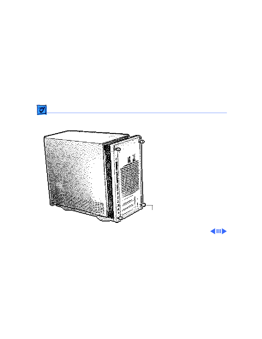
Top Housing - 1
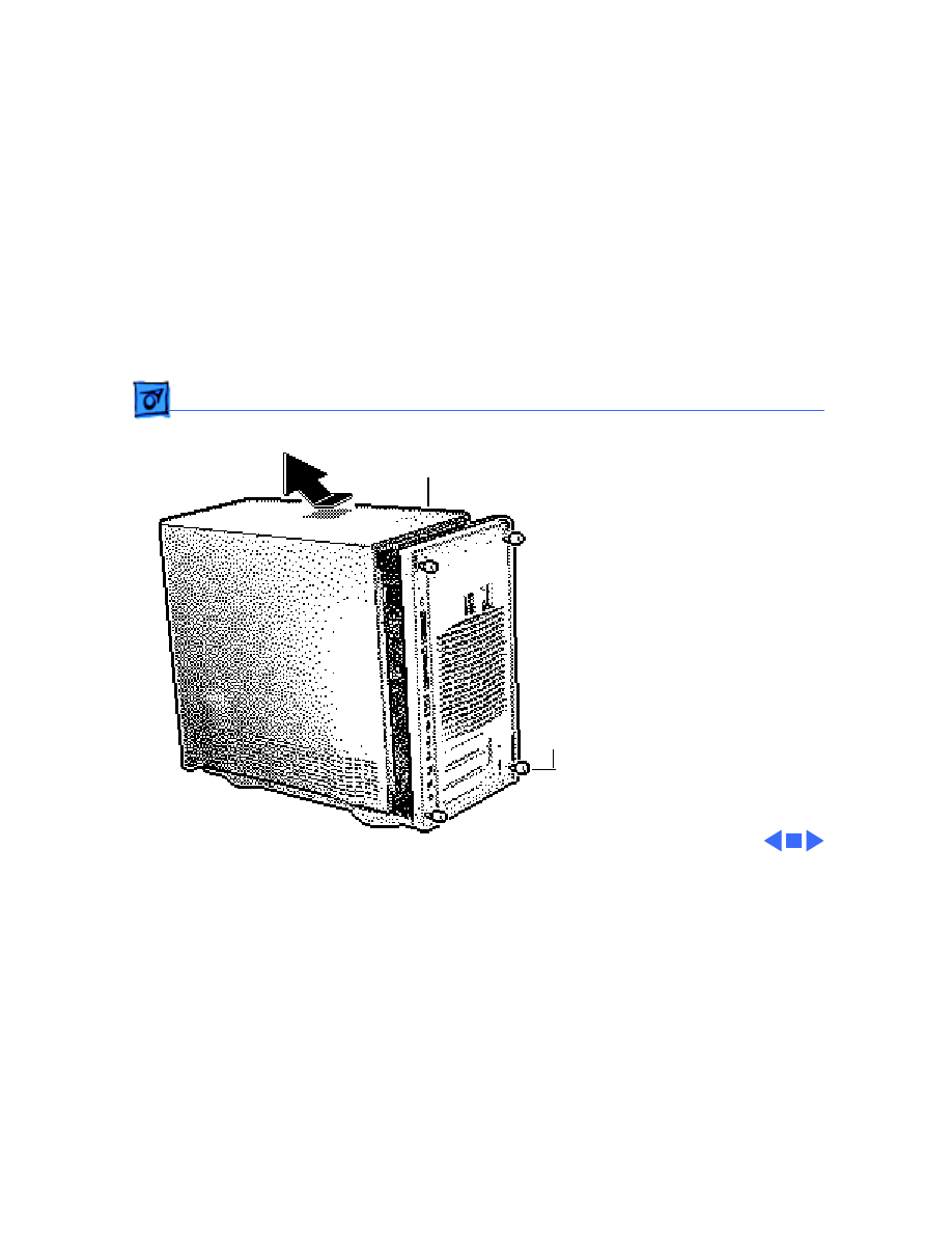
Top Housing
No preliminary steps are
required before you begin
this procedure.
1 Loosen the four captive
screws on the rear
panel.
2
Caution
: Be careful that
you don’t deform the
metal dome-shaped
shield inside the top
housing.
Slide the top housing
forward about 1/2 inch
and lift the top housing.
Top Housing
Captive
Screw

Take Apart
Floppy Drive - 2
Floppy Drive
Before you begin, remove
the following:
• Top housing
• CD-ROM drive
Caution:
To prevent ESD
damage, wear a grounding
wriststrap. Review the ESD
precautions in Bulletins/
Safety.
Floppy Drive
Take Apart
Floppy Drive - 3
1 Press down the retaining
clip securing the floppy
drive and slide the
floppy drive forward
about 2 inches.
2 Disconnect the floppy
drive cable from the
floppy drive.
3 Remove the floppy drive
from the chassis.
4 Remove the drive
carrier from the drive.

Take Apart
Hard Drive - 4
Hard Drive
Before you begin, remove
the top housing.
Caution:
To prevent ESD
damage, wear a grounding
wriststrap. Review the ESD
precautions in Bulletins/
Safety.
Hard Drive
Take Apart
Hard Drive - 5
1 Disconnect the SCSI data
cable and power cable
from the back of the hard
drive.
Note
: There are two in-
ternal SCSI connectors on
the logic board (see “Logic
Board Connectors” in
Basics for an illustration).
In the standard
configuration, the SCSI
connector at the top of the
logic board is used for the
CD-ROM/Tape drives, and
the SCSI connector near the
bottom of the logic board
(beneath the DRAM and
Retaining Clip
Take Apart
Hard Drive - 6
above the reset/interrupt
switch) is used for the
internal hard drive.
2 Press down the retaining
clip securing the hard
drive and slide the hard
drive out.
Replacement Note:
For
information on removing the
hard drive from its carrier
and returning drives,
cables, and carriers to
Apple, refer to Additional
Procedures in the Hard
Drives manual.
Retaining Clip
Take Apart
CD-ROM Drive - 7
CD-ROM Drive
Before you begin, remove
the top housing.
Caution:
To prevent ESD
damage, wear a grounding
wriststrap. Review the ESD
precautions in Bulletins/
Safety.
CD-ROM
Drive
Take Apart
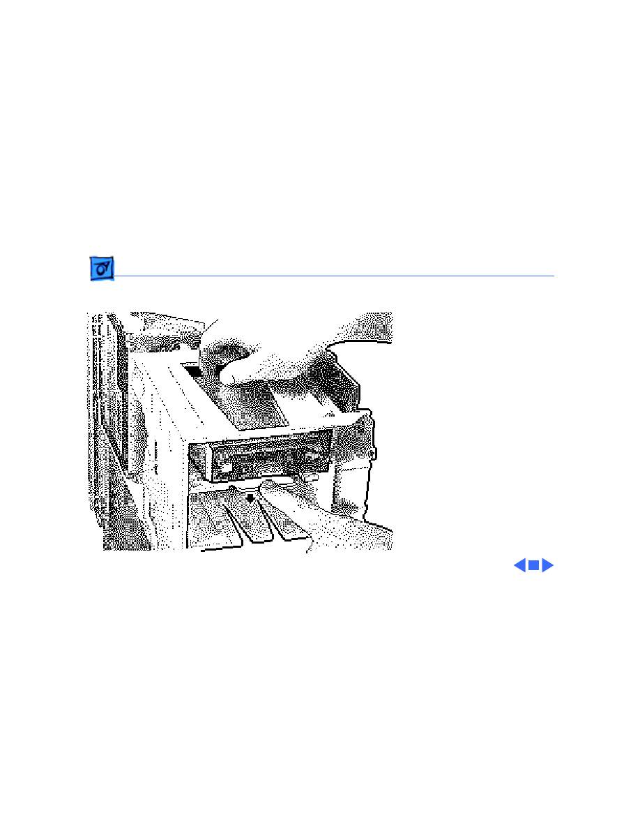
CD-ROM Drive - 8
1 Disconnect the SCSI data
cable, audio cable, and
power cable from the
back of the CD-ROM
drive.
Note
: There are two internal
SCSI connectors on the logic
board (see “Logic Board
Connectors” in Basics for an
illustration). In the
standard configuration, the
SCSI connector at the top of
the logic board is used for
the CD-ROM/Tape drives,
and the SCSI connector near
the bottom of the logic board
(directly beneath the DRAM
Audio Cable
Retaining Clip

Take Apart
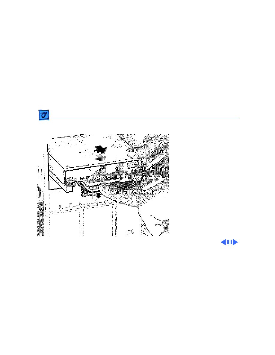
CD-ROM Drive - 9
and above the reset/
interrupt switch) is used
for the internal hard drive.
2 Pull up on the retaining
clip securing the CD-
ROM drive and slide the
CD-ROM drive out.
Replacement Note:
Be sure
to remove the CD-ROM drive
from the carrier prior to
returning the drive to Apple.
Audio Cable
Retaining Clip
Take Apart
Tape Drive - 10
Tape Drive
Before you begin, remove
the top housing.
Caution:
To prevent ESD
damage, wear a grounding
wriststrap. Review the ESD
precautions in Bulletins/
Safety.
Tape
Drive
Take Apart
Tape Drive - 11
1 Disconnect the SCSI data
cable and power cable
from the back of the tape
drive.
Note
: There are two internal
SCSI connectors on the logic
board (see “Logic Board
Connectors” in Basics for an
illustration). In the
standard configuration, the
SCSI connector at the top of
the logic board is used for
the CD-ROM/Tape drives,
and the SCSI connector near
the bottom of the logic board
(directly beneath the DRAM
and above the reset/
SCSI Data Cable
Tape Drive Power Cable
Take Apart
Tape Drive - 12
interrupt switch) is used
for the internal hard drive.
2 Press down the retaining
clip securing the tape
drive and slide the tape
drive out.
Replacement Note:
Be sure
to remove the tape drive
from the carrier prior to
returning the drive to Apple.
Tape Drive
Take Apart
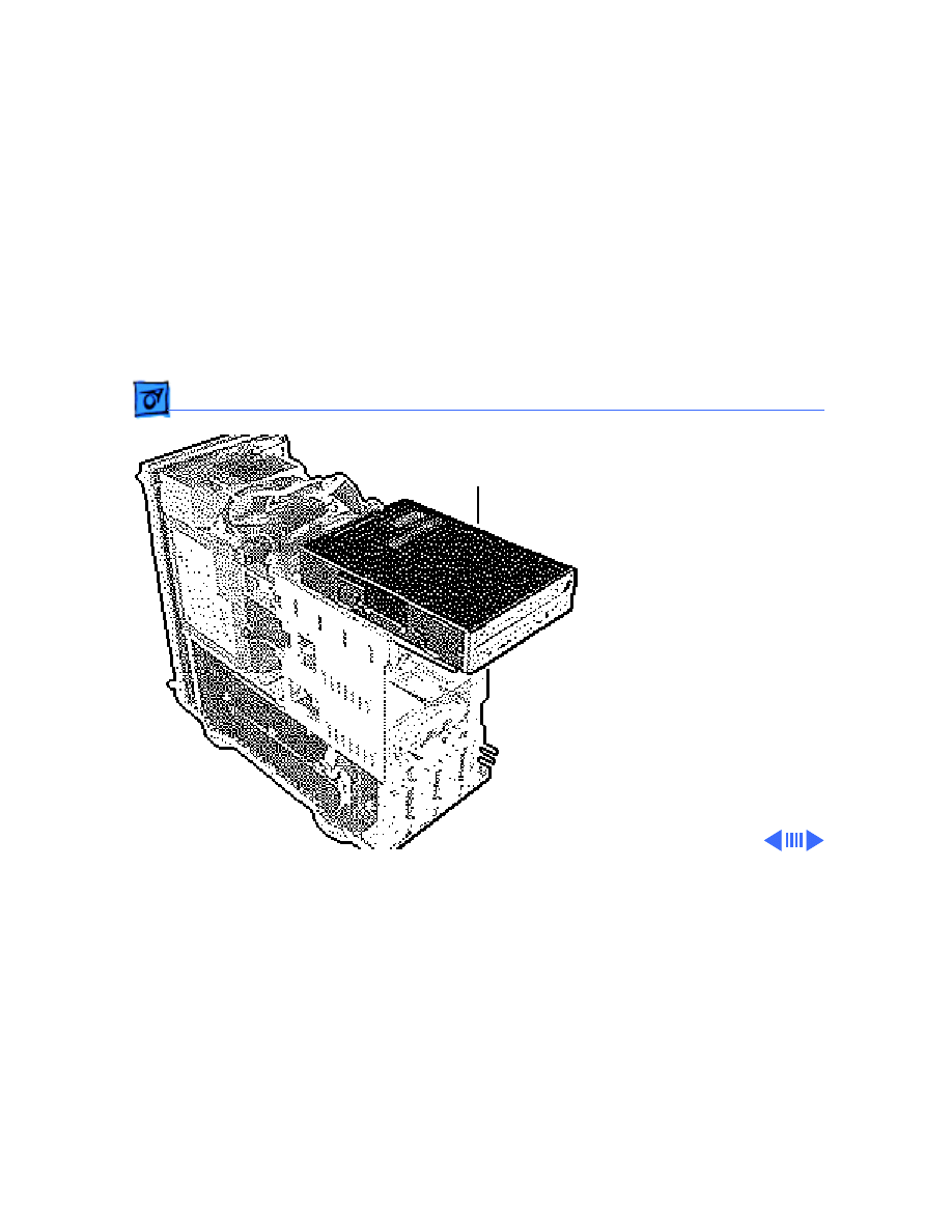
Video Card - 13
Video Card
Before you begin, remove
the top housing.
Caution:
To prevent ESD
damage, wear a grounding
wriststrap. Review the ESD
precautions in Bulletins/
Safety.
Take Apart
Video Card - 14
Note
: All Power Macintosh
8100 series computers
require that a video card or
PDS termination card be
installed in the PDS slot.
This procedure describes
how to remove either of
these cards.
Ê
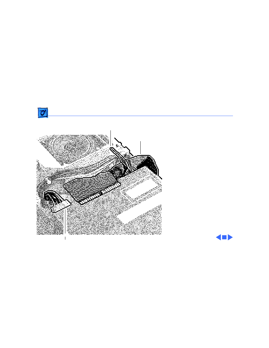
Take Apart
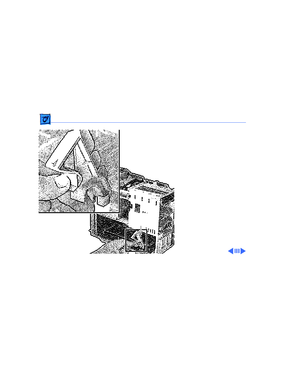
Video Card - 15
1 Push up on the tab that
secures the video card to
the chassis.
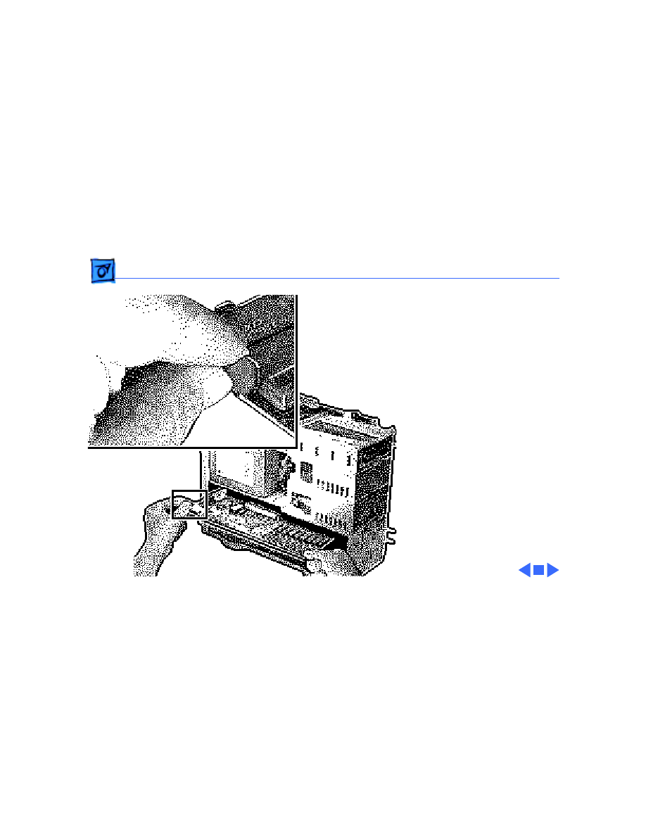
Take Apart
Video Card - 16
2 Gently pull
out the video
card to remove it.
Replacement Caution:
When replacing the card,
do not force it into the
expansion slot. If the
card does not seat
properly, remove the
card, check the logic
board for damage, and
try to install the card
again.
Take Apart
Logic Board - 17
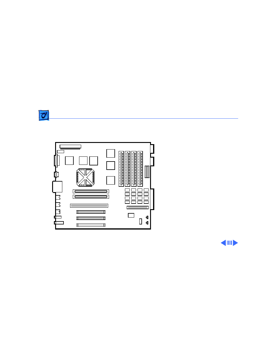
Logic Board
Before you begin, remove
the following:
• Top housing
• Video card
Logic
Board

Take Apart
Logic Board - 18
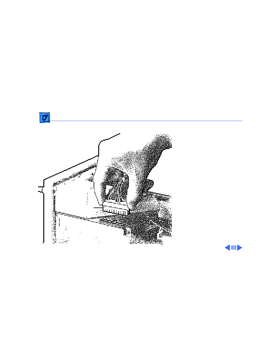
1 Disconnect the following
cables from the top of
the logic board:
• Logic board power
cable
• Speaker cable
• LED cable
• CD-ROM/Tape Drive
SCSI cable
• Floppy drive cable
• CD-ROM audio cable
(if present)
2 Disconnect the SCSI
hard drive cable from
the logic board.
Replacement Note:
There
are two internal SCSI
Take Apart
Logic Board - 19
connectors on the logic board
(see “Logic Board
Connectors” in Basics for an
illustration). In the
standard configuration, the
SCSI connector at the top of
the logic board is used for
the CD-ROM/Tape drives,
and the SCSI connector near
the bottom of the logic board
(directly beneath the DRAM
and above the reset/
interrupt switch) is used
for the internal hard drive.
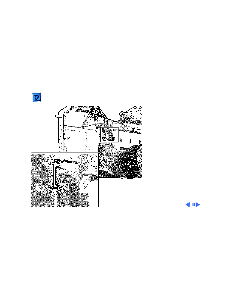
3 Remove the reset/
interrupt actuator.
4 Remove the screw
Take Apart
Logic Board - 20
securing the logic board.
Replacement Note:
When replacing a Power
Mac 8100 series logic
board, move the thermo-
electric cooling device
wires out of the way of
the center hole before
screwing down the logic
board. (See “Logic Board
Connectors” in Basics
for a description of the
thermoelectric cooling
device.)
5 Slide the logic board
forward until the slot
lines up with the tab.
Latch
Slot

Take Apart
Logic Board - 21
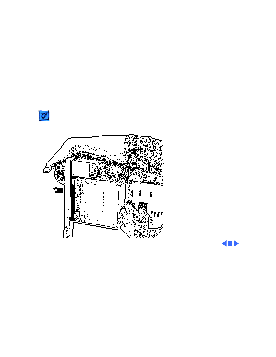
6 Lift the latch at the rear
of the logic board and
release the logic board.
Ê
Take Apart
Logic Board - 22
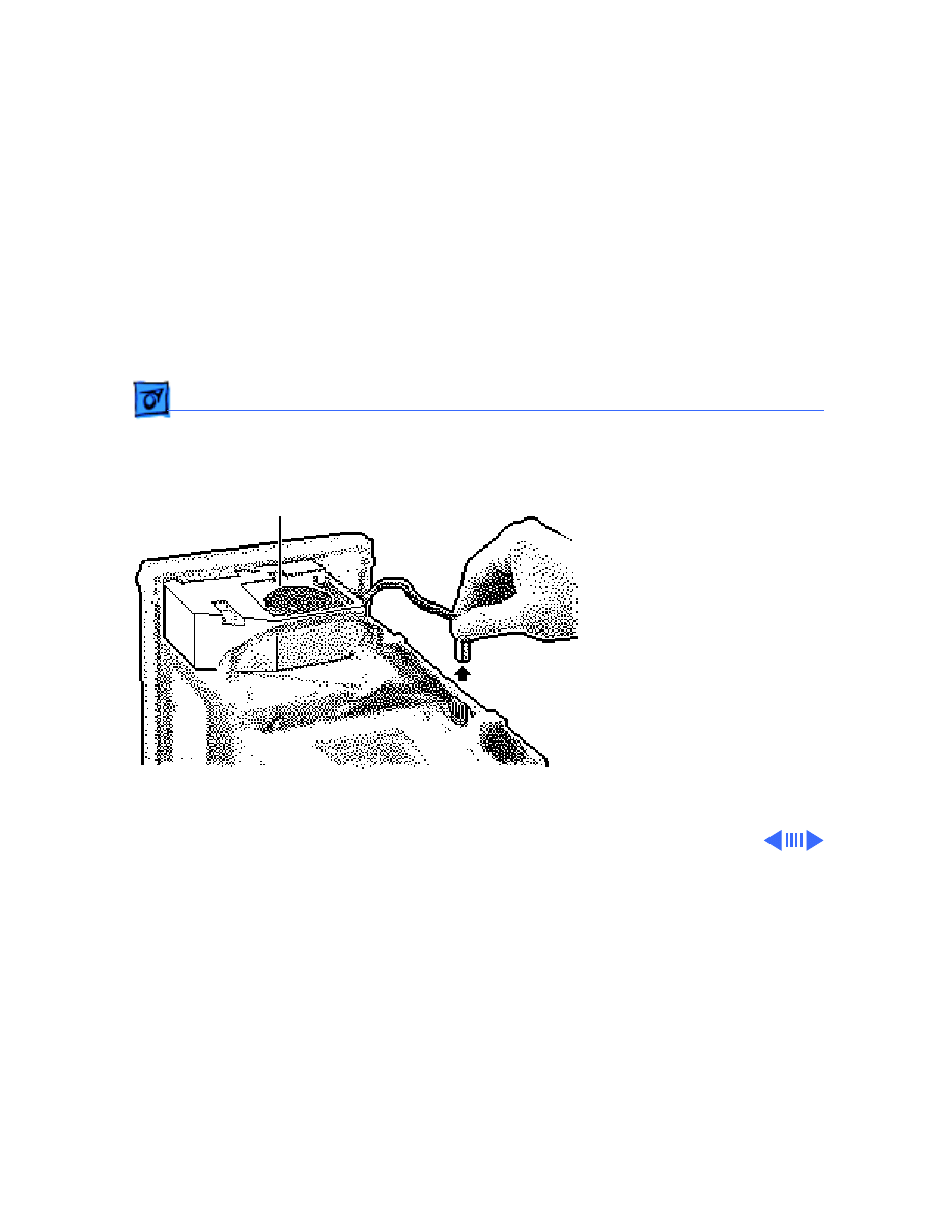
7 Pivot the front of the
logic board out of the
chassis.
Note:
Remove the 256K
cache SIMM and RAM SIMMs
before returning the board
to Apple, but do
not
remove
the ROM SIMM. Refer to the
parts database to identify the
cache SIMM.
Note
: Grasp the cache SIMM
by its corners and pull up to
remove it.
Replacement Note:
Be sure
to reconnect the LED cable to
the logic board.
Take Apart
Power Supply - 23
Power Supply
Before you begin, remove
the top housing.
Caution:
To prevent ESD
damage, wear a grounding
wriststrap. Review the ESD
precautions in Bulletins/
Safety.
Power Supply
Take Apart
Power Supply - 24
1 Remove the chassis
support brace.
Ê
Chassis Support
Brace
Take Apart
Power Supply - 25
2 Disconnect the logic
board power cable.
Ê
Logic Board
PowerCable
Take Apart
Power Supply - 26
3 Press the latch to
release the power
supply.
Ê
Latch
Take Apart
Power Supply - 27
4 Slide the power supply
forward.
5 Pull the power supply
out of the computer.
Take Apart
Speaker - 28
Speaker
Before you begin, remove
the top housing.
Caution:
To prevent ESD
damage, wear a grounding
wriststrap. Review the ESD
precautions in Bulletins/
Safety.
1 Disconnect the speaker
cable from the logic
board.
Speaker
Take Apart
Speaker - 29
2 Press the latch holding
the speaker housing to
the chassis and lift the
front of the speaker
housing.
3 Pull the speaker
housing from the clips at
the rear of the chassis.
Latch

Take Apart
Rear Panel - 30
Rear Panel
Before you begin, remove
the following:
• Top housing
• Speaker
Ê
Rear
Panel
Take Apart
Rear Panel - 31
1 Lift the two latches and
pull the rear panel loose.
Ê
Latch
Take Apart
Rear Panel - 32
2 Remove the rear panel
from the computer.

Service Source
K
Additional Procedures
Power Macintosh 8100/WS 8150

Additional Procedures
Battery Verification - 1
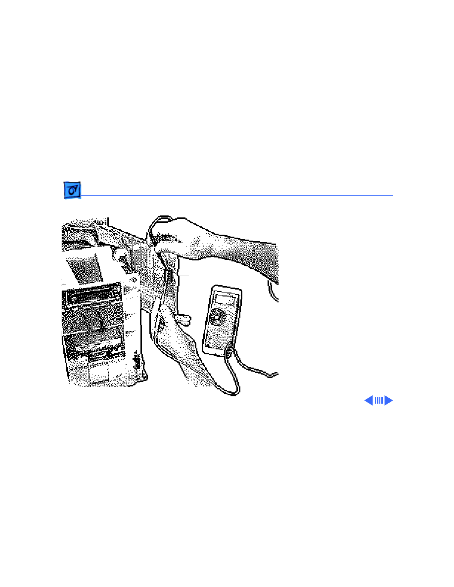
Battery
Verification
Before you begin, remove
the following:
• Top housing
• Logic board
Warning
: If handled or
discarded improperly, the
lithium battery could
explode. Review battery-
handling and disposal
instructions in Bulletins/
Safety.
Battery
Additional Procedures
Battery Verification - 2
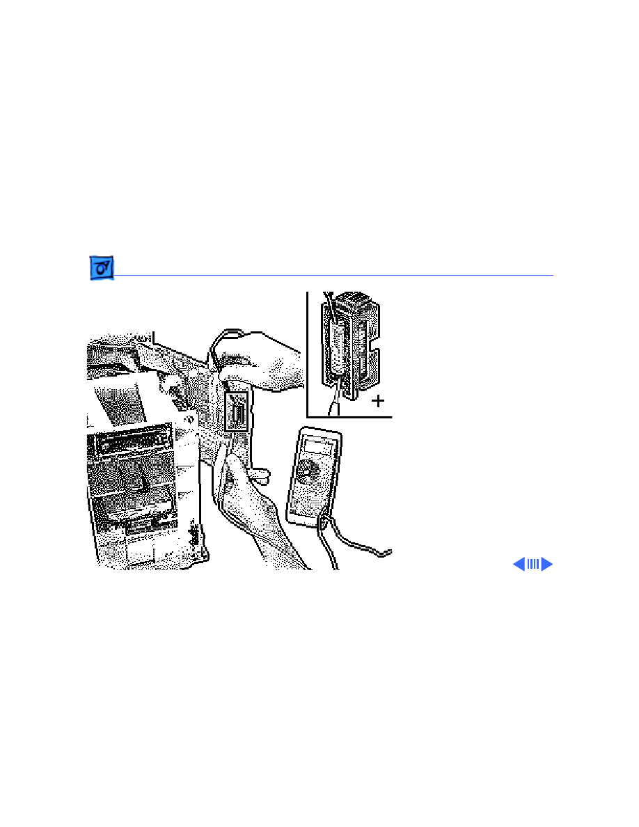
1 Set the voltmeter to 10
volts DC scale.
2 Hold the positive probe
of the voltmeter to the
positive end of the
battery (“+” on the
logic board) and the
negative probe to the
battery’s negative end.
3 If the battery voltage is
below 3.2 volts, replace
the battery. Refer to
“Battery Replacement.”

Additional Procedures
Battery Verification - 3
Note
: Make sure the
battery is installed in
the correct +/-
direction.
Additional Procedures
Battery Replacement - 4
Battery
Replacement
Before you begin, remove
the following:
• Top housing
• Logic board
Warning
: If handled or
discarded improperly, the
lithium battery could
explode. Review battery-
handling and disposal
instructions in Bulletins/
Safety.
Battery

Additional Procedures
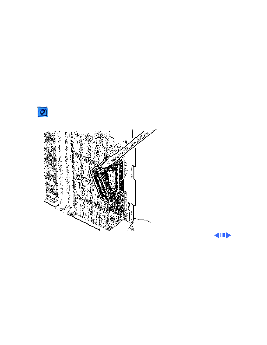
Battery Replacement - 5
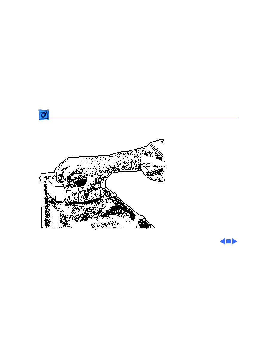
1 Using a small flat-blade
screwdriver, pry open
the latch at the end of the
battery holder and lift
off the cover.
Ê

Additional Procedures
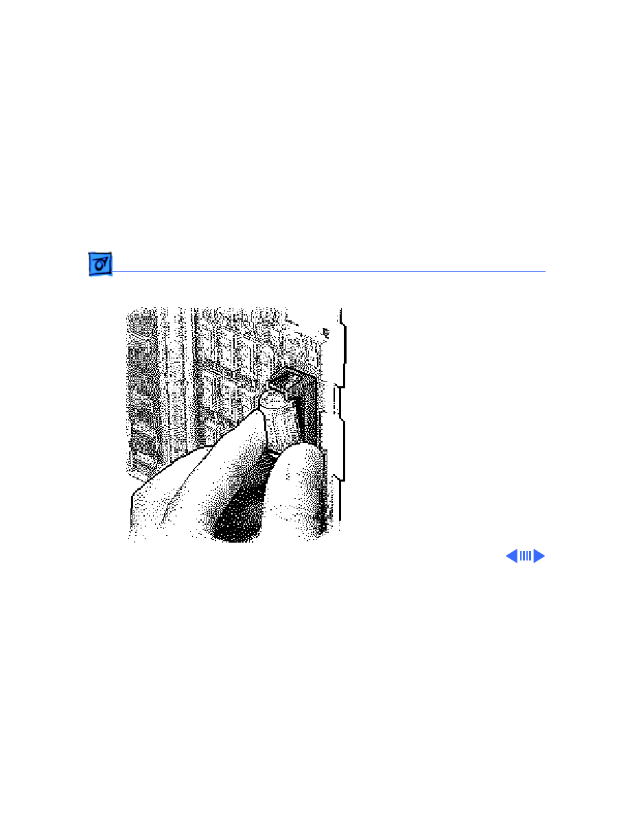
Battery Replacement - 6
2 Grasp the battery and
remove it from the
holder.
3 Return the battery to
Apple for proper
disposal. For battery
packaging and labeling
instructions, refer to
the safety information in
Bulletins/Safety.
Note
: Make sure the
battery is installed in
the correct +/-
direction.
Additional Procedures
Reset Logic Board - 7
Reset Logic Board
Before you begin, remove
the following:
• Top housing
• Power cord
• Logic board
Note
: Whenever you have a
unit that fails to power up,
you should follow this
procedure to reset the logic
board
before
replacing any
modules.
Ê
Additional Procedures
Reset Logic Board - 8
Warning
: If handled or
discarded improperly, the
lithium battery could
explode. Review battery-
handling and disposal
instructions in Bulletins/
Safety.
1 Unplug the computer
first.
2 Using a small flat-blade
screwdriver, pry open
the latch at the end of the
battery holder and lift
off the cover.
Ê
Additional Procedures
Reset Logic Board - 9
3 Grasp the battery and
remove it from the
holder.
Ê
Additional Procedures
Reset Logic Board - 10
4 Press the computer’s
power-on button. Verify
that the power supply
cable is disconnected
from the logic board.
Wait 5–10 minutes and
then:
• Replace battery
• Reassemble computer
Note
: Make sure the battery
in installed in the correct
+/- direction.
Note
: This procedure resets
PRAM. Be sure to check the
computer’s time/date and
other PRAM settings.
Power-on
Button
Power Supply
Connector

Additional Procedures
Reset Logic Board - 11
Note
: If this procedure
resolves the problem, claim
an adjustment on an SRO. If
not, replace the defective
component and
do not
claim
the adjustment procedure.
Service Source
K
Upgrades
Power Macintosh 8100/WS 8150
Upgrades
Expansion Cards - 1
Expansion Cards
Before you begin, remove
the top housing.
Caution
: To prevent ESD
damage to components, wear
a grounding wriststrap.
Review the ESD precautions
in Bulletins/Safety.
1 Pinch the two handles
and remove the NuBus
card retainer.
NuBus Card
Retainer
Upgrades
Expansion Cards - 2
2
Caution
: Pull up evenly
on both sides of the card
to avoid bending the
connector pins.
Carefully grasp each end
of the card and pull
straight out to remove it.
Note
: Grab the left side
of the card by the metal
bracket.
Replacement Caution
:
Do not force the card into
the expansion slot. If the
card does not seat
properly, remove it and
try again.
Upgrades
CD-ROM Upgrade - 3
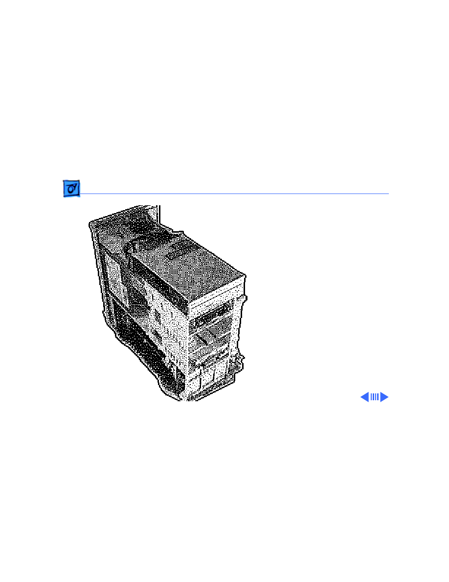
CD-ROM Upgrade
Before you begin, remove
the top housing.
Caution
: To prevent ESD
damage to components, wear
a grounding wriststrap.
Review the ESD precautions
in Bulletins/Safety.
Upper Blank Bezel
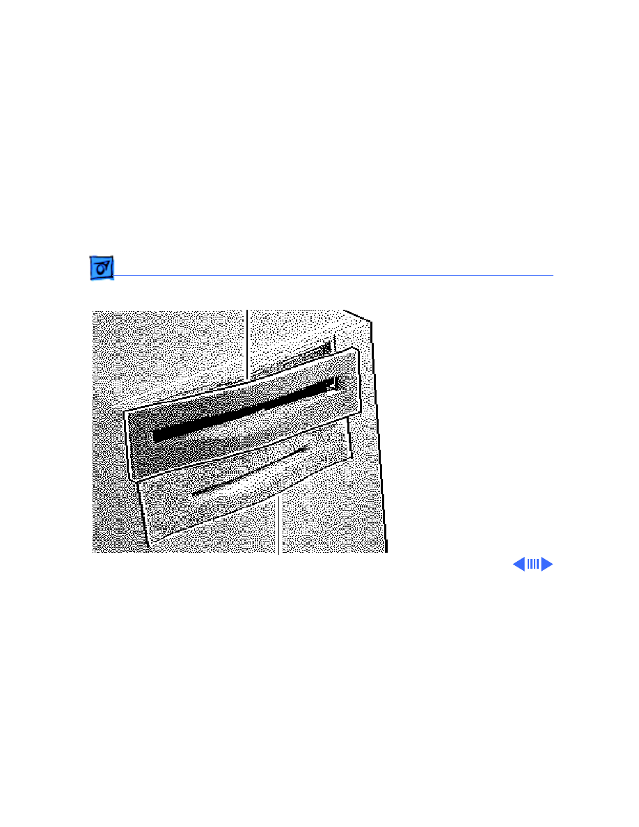
Upgrades
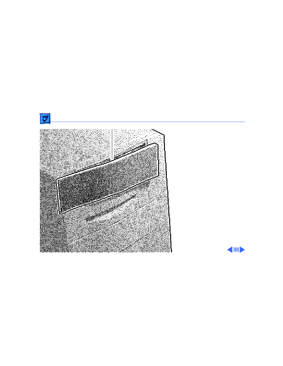
CD-ROM Upgrade - 4
1 Remove the upper blank
bezel from the top
housing.
Upper Blank Bezel
Upgrades
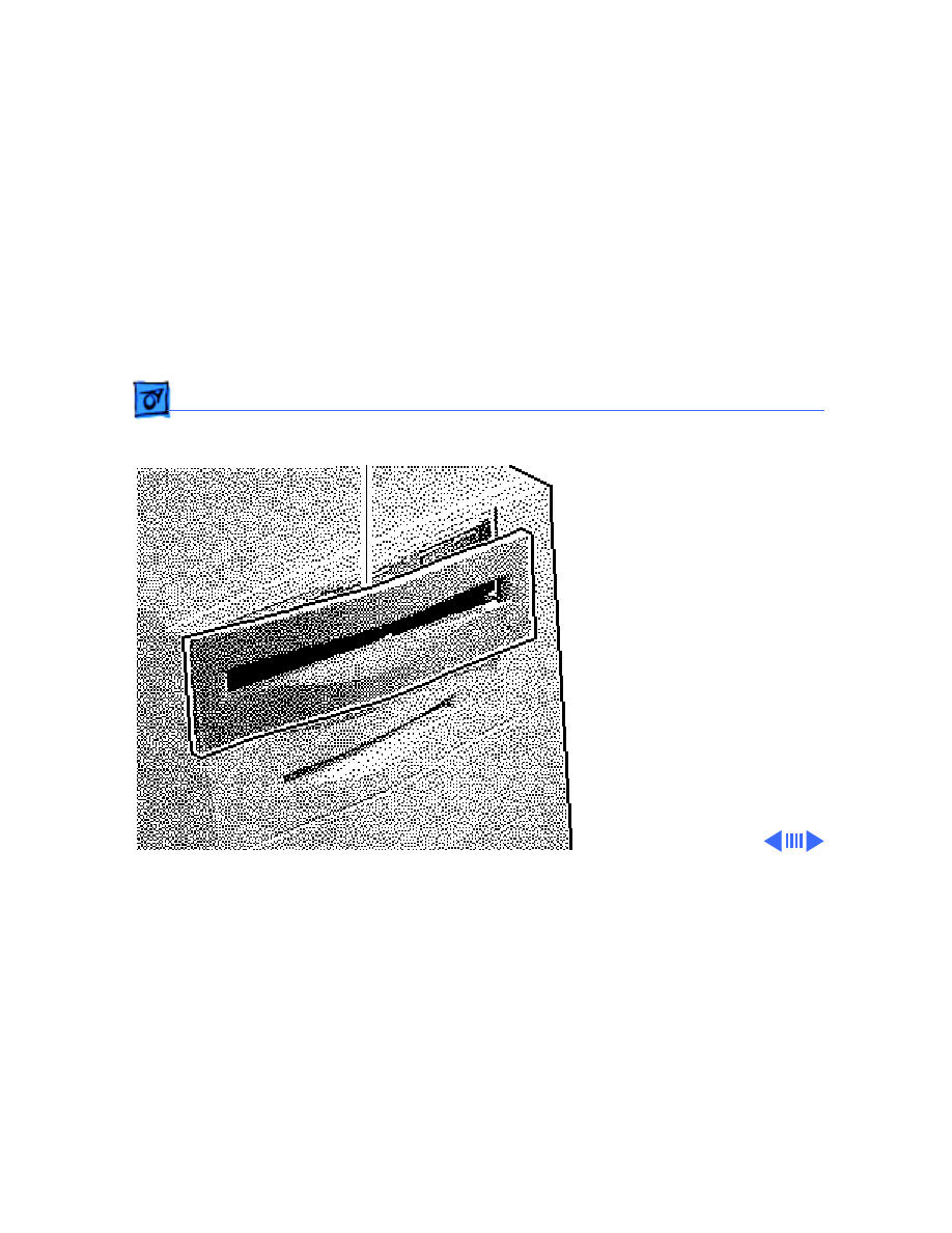
CD-ROM Upgrade - 5
2 Install the slotted CD-
ROM drive bezel in the
top housing.
Ê
CD-ROM Drive Bezel
Upgrades
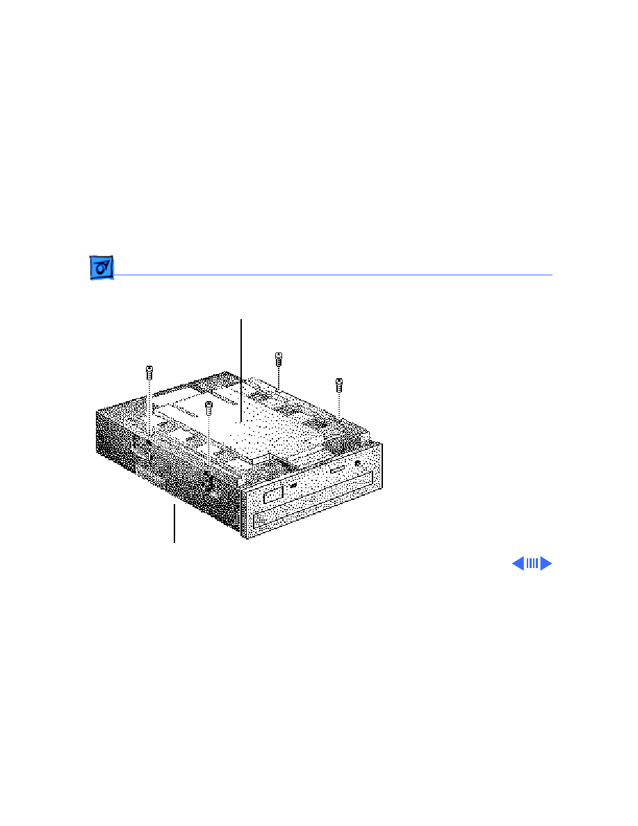
CD-ROM Upgrade - 6
3 Attach the CD-ROM
carrier to the CD-ROM
drive with four Phillips
screws.
Ê
CD-ROM Carrier
CD-ROM Drive
Upgrades
CD-ROM Upgrade - 7
4 Verify that the three
jumper connectors are
installed as shown.
Important
: These
jumpers configure the
SCSI device address of
the CD-ROM drive. The
CD-ROM drive will have
a SCSI device ID of 3.
Verify that no other SCSI
device installed in the
computer already has
that address. If another
device does have an ID of
3, change the ID prior to
installing the CD-ROM
drive.
Jumper Connectors
Upgrades
CD-ROM Upgrade - 8
5 Slide in the CD-ROM
drive and carrier.
Ê
CD-ROM Drive and Carrier
Upgrades
CD-ROM Upgrade - 9
6 Connect these cables to
the CD-ROM drive:
• Audio cable
• SCSI data cable
• CD-ROM drive power
cable
Audio Cable
SCSI Data Cable
CD-ROM Drive Power Cable
Upgrades
Power Macintosh Upgrade - 10
Power Macintosh
Upgrade
Before you begin, remove
• Top housing
• Top housing bezels
• Floppy drive
• Hard drive
• CD-ROM drive (if
present)
• Logic board
• Power supply
• Speaker
Note
: The Power Macintosh
8100/80 logic board
upgrades a Quadra 800 or
840AV. The WS 8150 logic
Power Macintosh 8100 Series
and WS 8150 Logic Board
Upgrades
Power Macintosh Upgrade - 11
board upgrades an AWS 80.
Note
: The upgrade kit con-
tains a logic board, internal
chassis, top housing, CD-
ROM and hard drive SCSI
cables, SCSI power cable,
reset/interrupt actuator,
and video card.
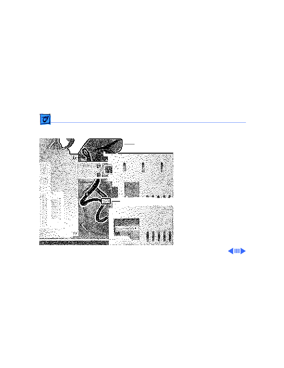
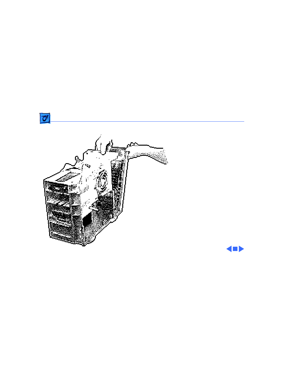
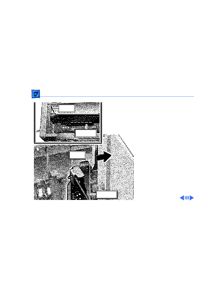
1 Remove the following
cables from the old logic
board and connect them
to the new logic board:
• LED cable
• Speaker cable
• CD-ROM audio cable
• Floppy drive cable
Speaker
CD-ROM
Audio
Floppy
Drive
LED
Upgrades
Power Macintosh Upgrade - 12
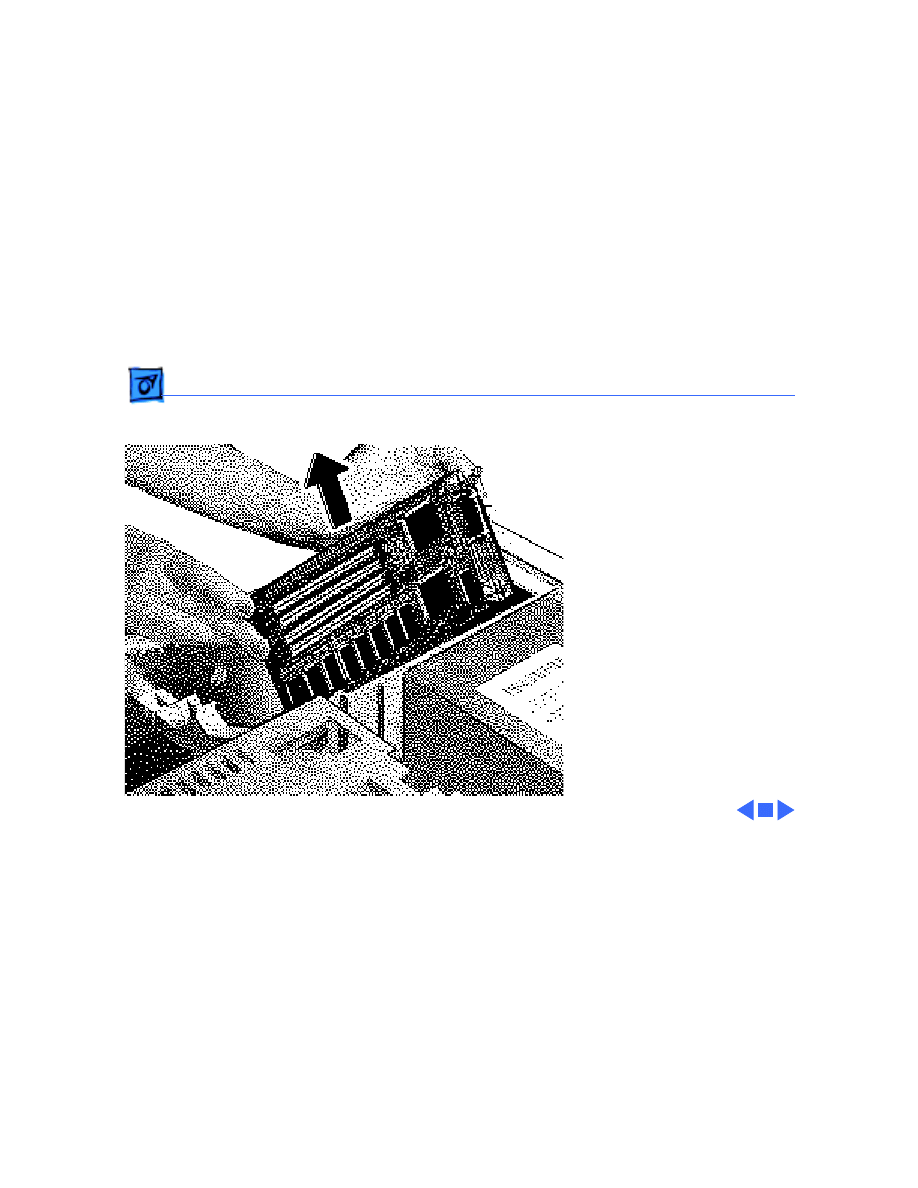
2 Install the speaker in the
upgraded chassis.
3 If the customer’s
original logic board had
DRAM SIMMs installed,
remove them and install
them on the upgraded
logic board.
Important
: Upgraded units
require that DRAM SIMMs
be installed in matching
pairs (i.e., same size and
speed). The SIMMs must be
80 ns or faster, non-
composite, 72-pin SIMMs.

Upgrades
Power Macintosh Upgrade - 13
Replacement Note:
Return
all VRAM and non-matching
DRAM SIMMs from the old
logic board to the customer.
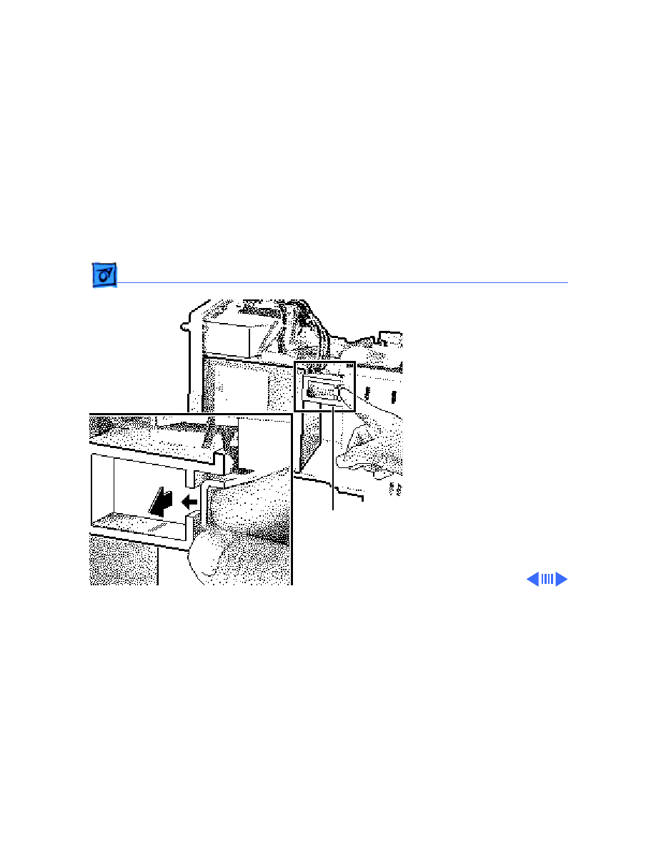
4 Remove the existing
power cable from the
power supply and the
SCSI cables from the
hard drive and CD-ROM
drive.
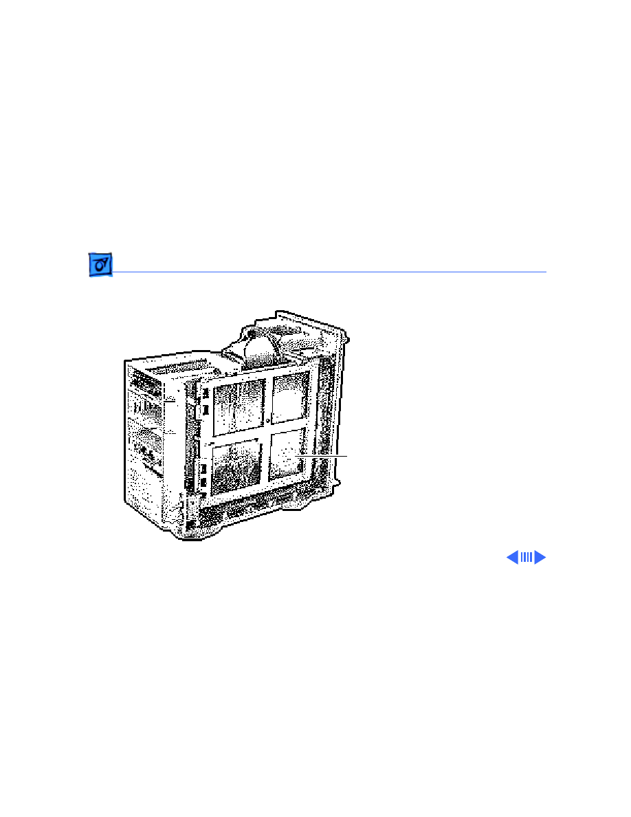
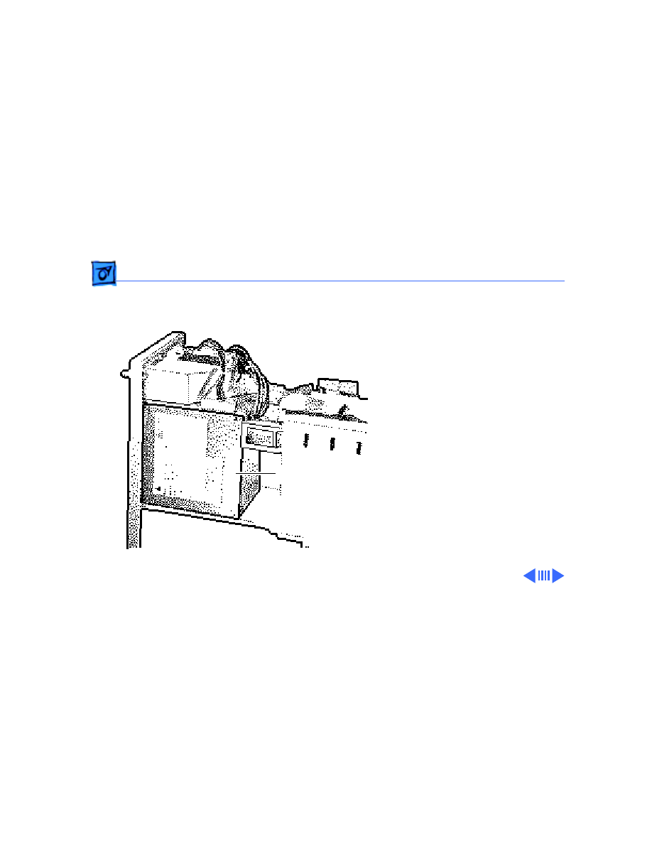
5 Install the floppy drive,
hard drive, CD-ROM
drive (if present),
power supply, and
speaker in the upgraded
internal chassis.
Speaker
Power
Supply
CD-ROM
Floppy Drive
Hard Drive

Upgrades
Power Macintosh Upgrade - 14
Note
: The upgrade kits ship with new SCSI cables and a new
power cable attached to the logic board. The equivalent cables
in the original unit are
not
forward compatible. You must
use the new SCSI and power cables provided in the kit.
Replacement Note:
The top SCSI cable connects to the CD-
ROM unit. The bottom SCSI cable connects to the hard drive.
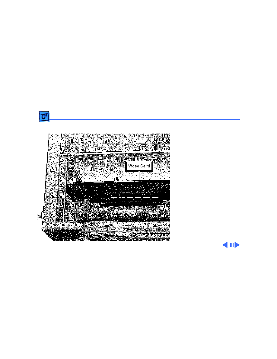
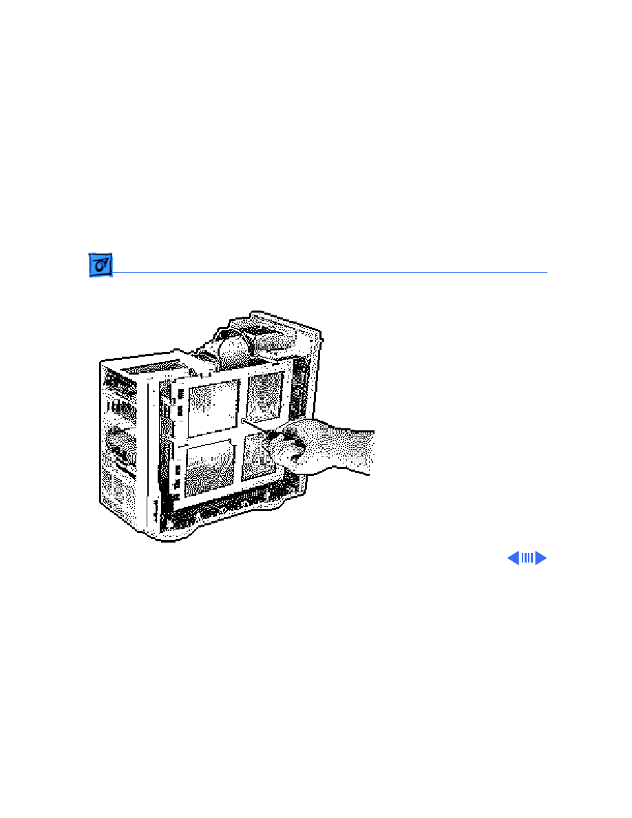
Note
: These upgraded units
must
have a video card installed
for proper bus termination. The 8100/80 requires the
Power Macintosh 4 MB Video Card; the 8100/80AV requires
the Power Macintosh AV Card. The WS 8150 requires a video
terminator card.
Upgrades
Power Macintosh Upgrade - 15
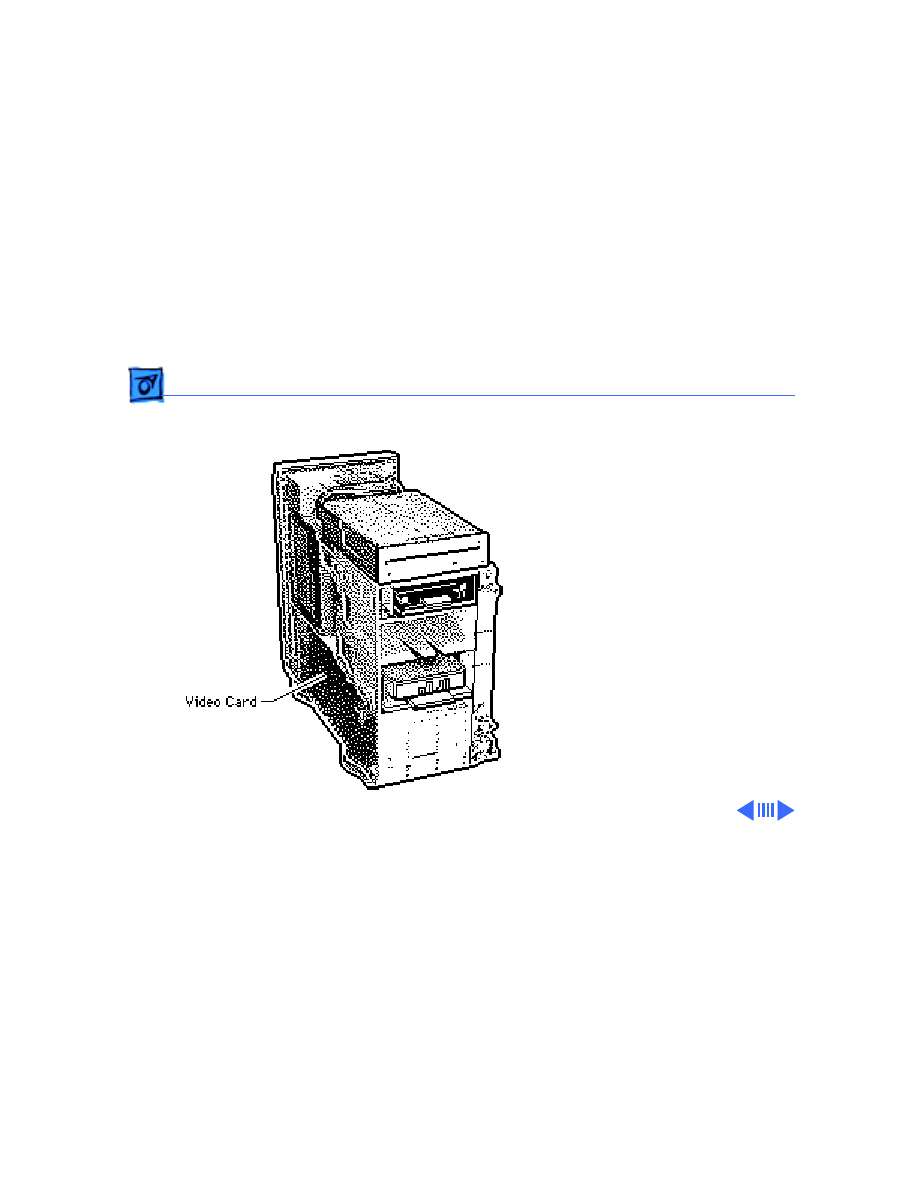
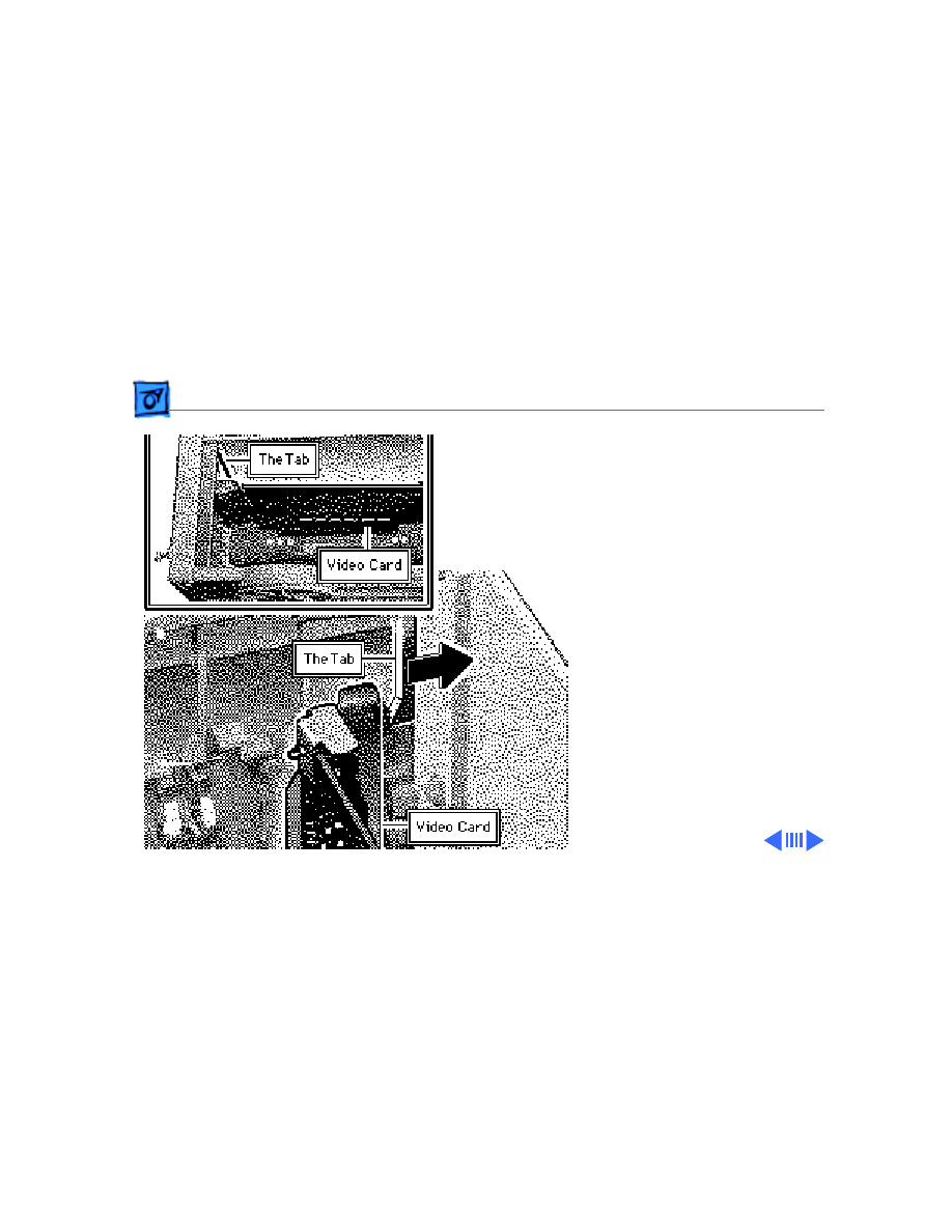
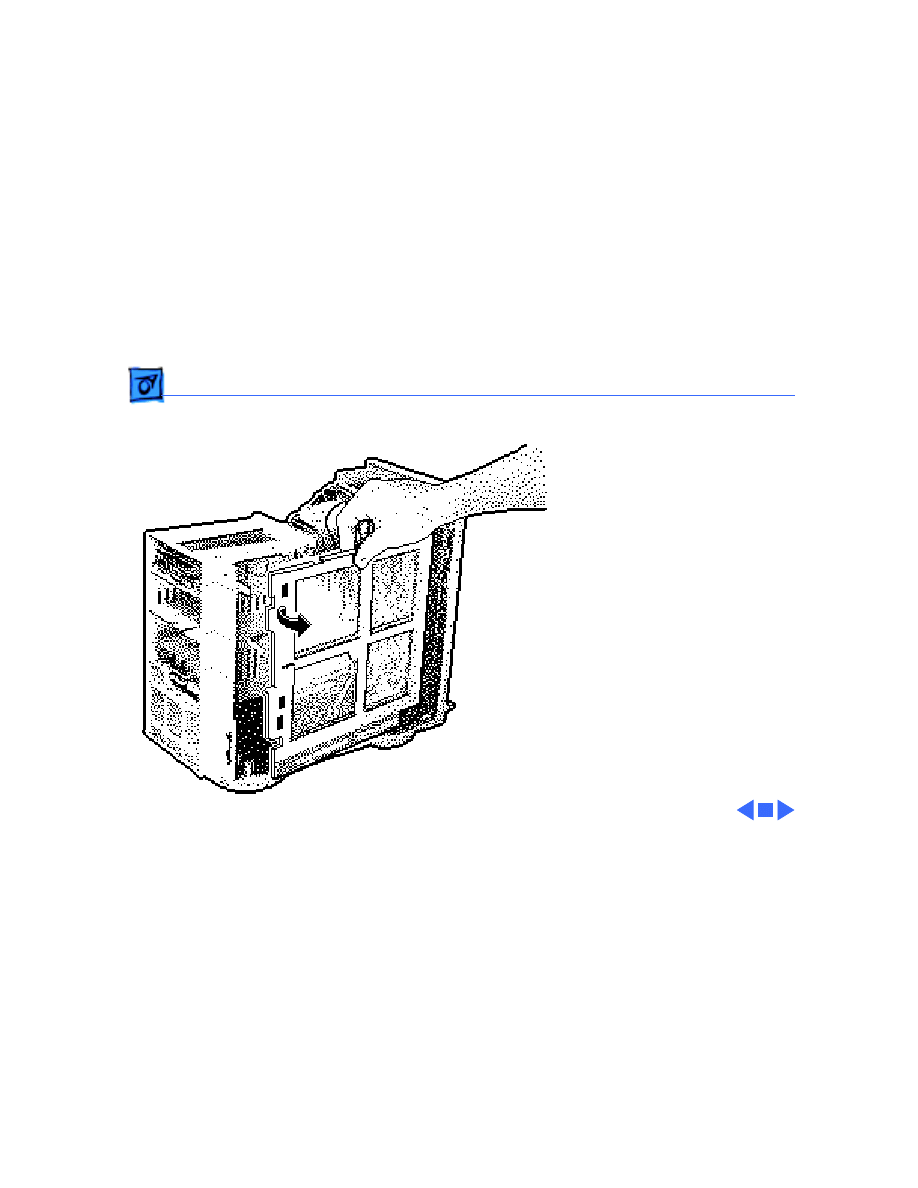
Caution
: Install the video
card at an angle, inserting
the back end (the non-
connector end) first. Do not
force the card into the
expansion slot. If the card
does not seat properly,
remove the card, check the
logic board for damage, and
try to install the card again.
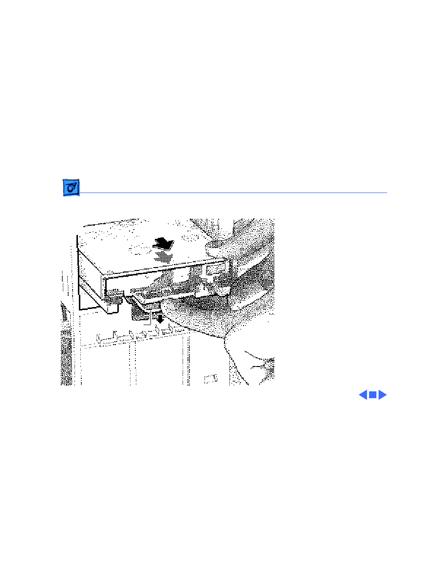
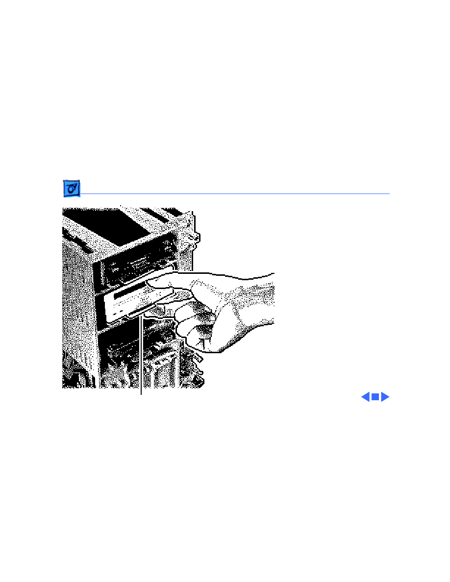
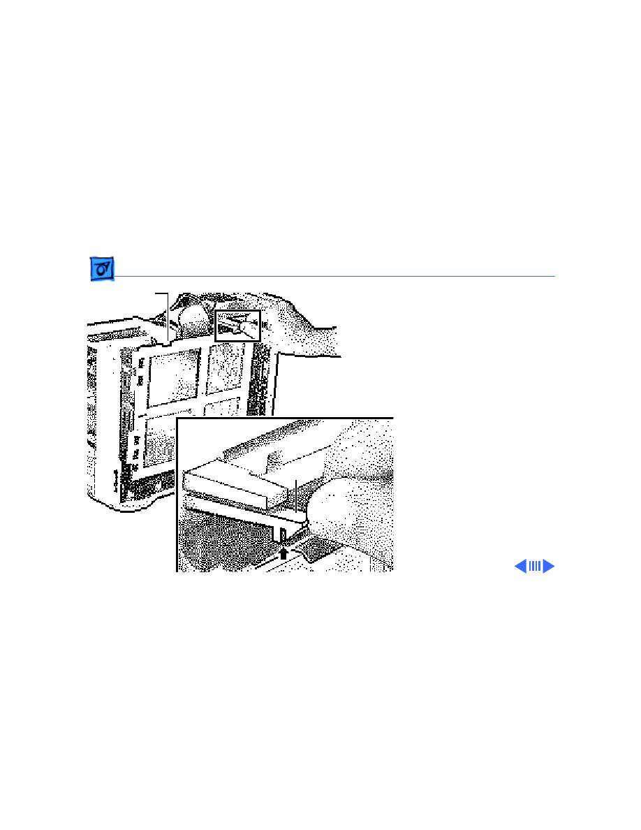
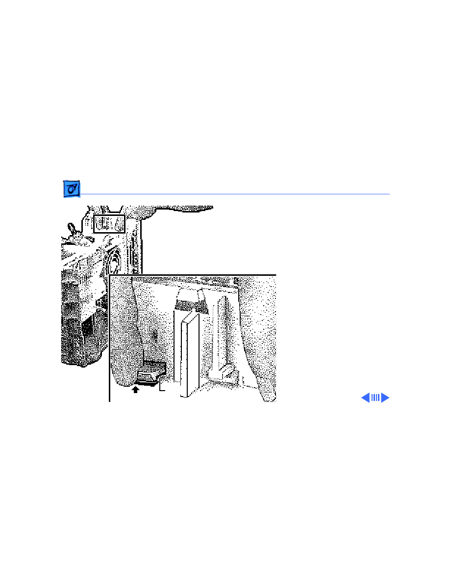
6 Gently push down on the
video card until it snaps
into place.
Replacement Note:
Push
up on the tab that holds
the video card in place to
remove the card.
The Tab
Video Card
The Tab
Video Card
Upgrades
Power Macintosh Upgrade - 16
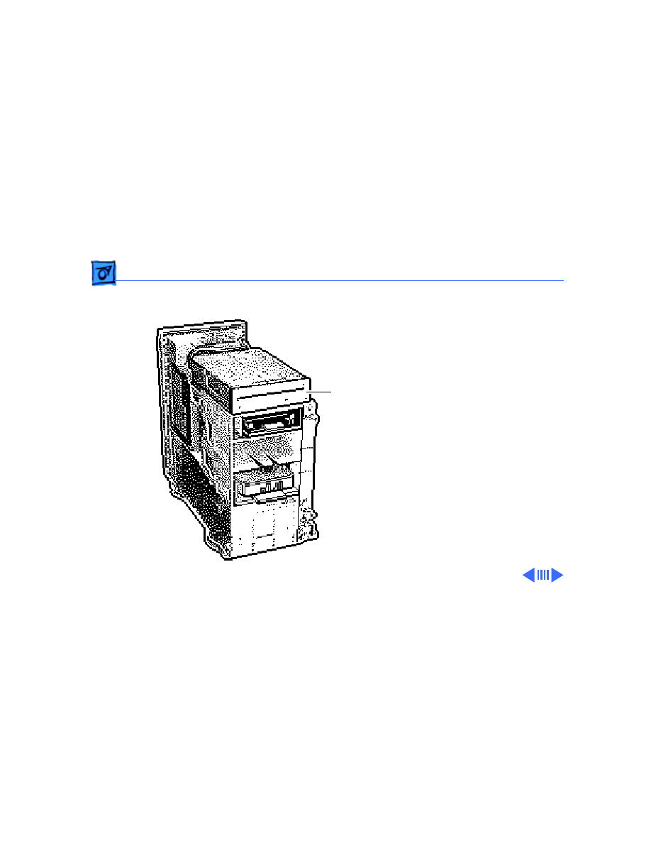
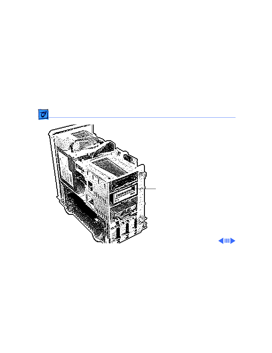
7 Remove the bezels from
the old top housing and
install them on the new
top housing.
8 Copy the computer’s
serial number from the
old top housing to the
new top housing.
Note
: A blank serial
number label is provided
on the new top housing.
Ê
CD-ROM Bezel
Floppy Drive Bezel
Upgrades
Power Macintosh Upgrade - 17
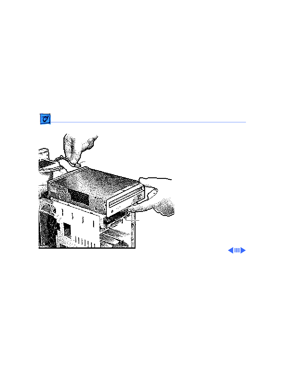
9 Move the top housing
screws from the old unit
to the new unit and
reassemble the
computer.
Note
: For the Power
Macintosh 8100/80 and
8100/80AV upgrades, you
must install the System
7.1.2 software that came
with the upgrade kit. Refer
to the user manual provided
in the upgrade kit for
installation instructions.
Top
Housing
Screw

Upgrades
Power Macintosh Upgrade - 18
10 Run MacTest Pro in looping mode or other software in
demo mode for 1 hour as a burn-in test.
Note
: Contact Finished Goods for an RMA number to return
the old logic board. Return the logic board in the old housing.
You do not need to return the cables to Apple.

Upgrades
Power Macintosh 8500 Upgrade - 19
Power Macintosh 8500 Upgrade
The Power Macintosh 8500 Upgrade Kit can be used to
upgrade a Quadra 800, Quadra 840, or a Power Macintosh
8100. The kit includes everything except:
• The peripherals (such as the hard drive, floppy drive,
and CD-ROM drive), which must be transferred from
the original unit you are upgrading
• A processor card, which must be purchased separately.
Refer to the appropriate Take Apart chapter (that is, the
Take Apart chapter in the Quadra 800, Quadra 840AV, or
Power Macintosh 8100 manual) for instructions on how to
remove the drives from the original unit.
Refer to the Take Apart chapter in the Power Macintosh
8500/WS 8550 manual to see where the peripherals should
be installed in the upgraded unit and for instructions on how

Upgrades
Power Macintosh 8500 Upgrade - 20
to install the processor card.
Once you have installed all the drives in the upgraded unit
and replaced the top housing, copy the serial number from
the original unit to the blank serial label on the upgraded
unit.

Upgrades
WorkGroup Server 8550/132 Upgrade - 21
WorkGroup Server 8550/132 Upgrade
The WorkGroup Server 8550/132 Upgrade Kit can be used
to upgrade a WorkGroup Server 80, 8150/80, or 8150/
110. The kit includes everything except:
• The peripherals (such as the hard drive, floppy drive,
and CD-ROM drive), which must be transferred from
the original unit you are upgrading
• Drive carriers
• Drive bezels
• Drive shields
• Speaker
• CD-ROM audio cable
• Floppy drive cable
• Power supply to logic board cable
• Chassis support bracket
• DRAM DIMMs

Upgrades
WorkGroup Server 8550/132 Upgrade - 22
All of the part listed above, except for the DRAM DIMMs,
need to be removed from the original unit and installed in the
upgraded unit. Refer to the Take Apart chapter for the
product from which you are upgrading for instructions on
how to remove these parts. Refer to the Take Apart chapter
in the Power Macintosh 8500/WS 8550 manual to see
where the peripherals should be installed in the upgraded
unit.
Note:
The WS 8550 logic board in the upgrade kit does not
contain any DRAM. You must install 64 bit-wide, 168-pin
DRAM DIMMs. The DIMMs should be fast-paged mode, 70 ns
or faster. You can use 8, 16, 32, or 64 MB DIMMs, which
can be installed in any configuration. For the best
performance, however, the DIMMs should be installed in
pairs of the same size into paired slots. The slower 80 ns
SIMMs and DIMMs used in older Macintosh computers will
not work reliably in the WS 8550.

Upgrades
WorkGroup Server 8550/132 Upgrade - 23
Once you have installed all the necessary parts in the
upgraded unit and replaced the top housing, copy the serial
number from the original unit to the blank serial label on
the upgraded unit.
Note
: The WorkGroup Server 8550/132 Upgrade Kit does
not include a hard drive bracket.

Service Source
K
Exploded View
Power Macintosh 8100/WS 8150
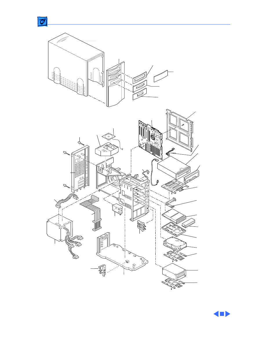
Exploded View
1
Top Housing
922-1277
Front Panel *
CD-ROM Bezel
Trayloading
922-0811
Blank Bezel
922-0620
Tape Drive Bezel
922-0969
Logic Board
Guard
922-0851
Logic Board*
661-0209
661-0199
661-1026
Speaker
922-0353
Speaker
Housing
922-0394
Thumbscrew
922-0395
Rear
Panel
922-0722
Power
Supply*
661-1687
661-0232
SCSI
Cable
922-0723
922-0803
Brace
922-0396
LED
Cable
922-0841
Reset
Interrupt
922-0843
Chassis
922-0888
NuBus
Retainer
922-0393
CD-ROM
Drive*
661-0913
CD-ROM
Carrier
922-0850
CD-ROM
Audio Cable
922-0724
Manual Insert
Floppy Drive
661-0121
Floppy Drive
Carrier
922-0445
Hard Drive*
Hard Drive
Carrier
922-0621
Tape Drive*
661-0039
Tape Drive
Carrier
922-0621
Floppy Drive
Cable
922-0872
Power
Supply
Cable
922-0838
Power Macintosh 8100/WS8150
Floppy Drive Bezel
922-0523
Floppy Drive
Shield
922-0813
CD-ROM
Shield
922-0812
Product family configurations may vary. For parts with asterisk (*), refer to parts list.
Document Outline
- Power Macintosh 8100/WS 8150
- Basics
- Specifications
- Troubleshooting
- General
- Symptom Charts
- Power Supply
- Error Chords
- System
- System (Continued)
- System (Continued)
- System (Continued)
- Video
- Video (Continued)
- Video (Continued)
- Floppy Drive
- Floppy Drive (Continued)
- Floppy Drive (Continued)
- Hard Drive
- Hard Drive (Continued)
- Hard Drive (Continued)
- Peripherals
- Peripherals (Continued)
- Peripherals (Continued)
- Miscellaneous
- CD-ROM Drive
- Take Apart
- Additional Procedures
- Upgrades
- Exploded View
Wyszukiwarka
Podobne podstrony:
WS korelacja nowy
8150
IV SA Wa 198 08 Wyrok WSA w Warszawie ws zakazu reklamy świetlnej
Zobowiązanie ws okazania wyników badań
Ekologiczne podstawy systemu ws Nieznany
08 Podstawy obliczen i rachunek ws
Organizacja Bezpieczenstwa i Ws Nieznany
Współczesne Systemy Polityczne początek, Dziennikarstwo i komunikacja społeczna (KUL) I stopień, Rok
Irak i Chiny podpisały kontrakt ws eksploatacji irackiego złoża ropy
Cwiczenie 25 ws
11 WebService ESB WS
Obw M ws stawek opłat za korzystanie ze rodowiska
II C 182 13 (wyrok ws czesci ws system grzewczy) id 209803
Dz.U.2009.105 poz.870 Rozp. ws. ustalania okoliczności i przyczyn wypadków przy pracy, BHP, Akty pra
8100
8150
3xgu50 ws
Zwrot ws katastrofy Tu 154M Pismo Seremeta do Rosji
więcej podobnych podstron