
INTERFACES TG

We reserve the right to make changes in the course of technical development.
© 2007 MAN Nutzfahrzeuge Aktiengesellschaft
Reprinting, reproduction or translation, even of excerpts, is not permitted without the written permission of MAN.
All rights, in particular under copyright, are strictly reserved by MAN.
Trucknology
®
and MANTED
®
are registered trademarks of MAN Nutzfahrzeuge AG
Where designations are trademarks they are, even without the
®
or ™ sign, acknowledged as the proprietor‘s protected marks.
P U B L I S H E R
MAN Nutzfahrzeuge AG
E S C D e p a r t m e n t
Engineering Services
Consultation (formerly TDB)
D a c h a u e r S t r . 6 6 7
D - 8 0 9 9 5 M u n i c h
E - M a i l:
e s c @ m a n . e u
Fa x:
+ 4 9 (0) 8 9 15 8 0 4 2 6 4

Interfaces TG I
1
1
1
1
4
4
7
7
7
9
9
TG electrical and electronic interfaces
1. Wiring harnesses for wheelbase extensions
1.1 Procedure
1.2 Rear-axle related control units and sensors
1.3 Performing the work
2. Wiring harness for tail lights, additional tail lights, trailer tow sockets, side marker lights
and additional ABS sockets
3. Tapping the speed signal
4. Interfaces for intermediate speed control
4.1 Abbreviations and terms used
4.2 Interface mounting location
4.3 Description

Interfaces TG 1
1.
Wiring harnesses for wheelbase extensions
1.1
Procedure
Rear-axle control units and sensors are to be moved together with the axle if wheelbase extensions are to be carried out.
CAN wiring harnesses must never be cut or extended. MAN therefore offers wiring harness extensions with a corrugated pipe length
of 1,500mm. If these extensions prove inadequate, two such wiring harnesses can be plugged together.
Only when the method described here is used can the movement of control units and sensors be considered as approved.
1.2
Rear-axle related control units and sensors
Basic equipment on all TG vehicles:
•
EBS pressure control module (one module for all rear axles)
•
Parking brake warning lamp switch
If the rear axle(s) has air suspension, the following are also fitted:
•
Travel sensor (left and right)
•
ECAS valve block
Depending on design and equipment, the following cables are also present:
•
Plug connection for differential lock
Cable extensions from the EBS pressure control module to sensors on the respective wheel (speed sensor, brake lining wear sensors)
are not required if the EBS pressure control module is moved along with the rear axle assembly.
1.3
Performing the work
Some cable extensions require minor rework to the connector on the original wiring harness. A detailed description follows,
which includes the required incidental items such as connector housing, catches and adapters with code designations.
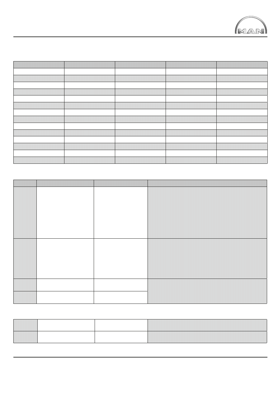
The corresponding order numbers are itemised in Table 1.
Interfaces TG 2
Table 1:
Itemised code numbers for incidental items
Code
Designation
MAN item number
Supplier
Supplier No.
AW64
Adapter
81.25433.0184
Schlemmer
7807 029 K
AW65
Adapter
81.25433.0182
Schlemmer
7807 025 K
BA20
Connector housing
81.25432.0337
Grote&Hartmann
18169 000 001
BA21
Connector housing
81.25432.0338
Grote&Hartmann
18170 000 001
BA28
Connector housing
81.25432.0347
Grote&Hartmann
18166 000 001
BA70
Connector housing
81.25432.0434
Grote&Hartmann
18385 000 001
BA71
Connector housing
81.25432.0433
Grote&Hartmann
18286 000 001
BA72
Connector housing
81.25432.0436
Grote&Hartmann
18284 000 001
BB68
Connector housing
81.25432.0435
Grote&Hartmann
18515 000 001
BB69
Connector housing
81.25432.0437
Grote&Hartmann
18516 000 001
BB70
Connector housing
81.25432.0438
Grote&Hartmann
18514 000 001
GV10
Catch slide
81.25435.0994
Grote&Hartmann
14816 660 636
GV12
Catch slide
81.25435.0996
Grote&Hartmann
14818 660 636
SS1
Shrinkdown plastic tube
81.96503.0008
Raychem
RBK 85KT 107 A 0
Table 2:
Wiring harness extensions
Range
Moved unit / sensor
Item no. Extension, qty
Description/rework
TGA
EBS pressure control
module on rear axle Y264
81.25453.6306
1 x 4-pin
Unplug 4-pin green connector (BA28) on frame wiring harness
from EBS pressure control module on rear axle. Remove
catch (GV12), eject contacts and push in a new housing
(BB69) with identical pin socket collar. Replace catch GV12.
Connect corrugated pipe and connector(BB69) using adapter
81.25433.0184 (AW 64).
Alternatively: Attach existing housing and wiring harness
extension with shrinkdown plastic tube (e.g. SS1) to
corrugated pipe.
TGL TGM
EBS pressure control
module on rear axle Y264
81.25453.6305
1 x 4-pin
Unplug the standard connector from the pressure control
module. Plug the extension into the connecting cable.
Plug the extended harness into the pressure module.
Note: On the TGL and TGA the same adapter is usedfor
extending wiring harness 81.25453.6305 from: EBS pressure
control module, differential lock, travel sensors on left and
right and the ECAS valve block.
TGA
Parking brake warning
lamp switch B369
81.25453.6305
1 x 4-pin
Unplug 4-pin DIN bayonet connection from Parking brake
warning lamp switch and lengthen using extension wiring
harness.
TGL TGM
Parking brake warning
lamp switch B369
85.25413.6345
1 x 4-pin
Table 3:
Equipment-dependent wiring harness extensions
TGA
Differential lock X637
81.25453.6307
1 x 4-pin
Split at point of separation X637 and insert extension in
between.
TGL TGM
Differential lock S185
81.25453.6305
1 x 4-pin
Same wiring harness for extending EBS pressure control
module, travel sensors and ECAS valve block.
Interfaces TG 3
Table 4:
Wiring harness extensions for air suspension on rear axles or on all axles
TGA
TGL TGM
Travel sensor on rear axle,
left B129
right B130
81.25453.6305
2 x 4-pin
(One each on L and R)
On TGA 4x2 tractor unit
only one travel sensor
On the TGL and TGM the same adapter is used for extending
wiring harness 81.25453.6305 from:
EBS pressure control module and differential lock.
TGA
TGL TGM
Valve block ECAS
Y132Twin-axle leaf/air
81.25453.6305
1 x 4-pin
TGA
TGL TGM
Valve block ECAS Y132/
61and Y132/62
Twin axle, air/air
81.25453.6305
2 x 4-pin
(per valve block)
TGA
TGL TGM
Valve block ECAS Y161/I
and Y161/II
> 2 axle, leaf/air and air/air
81.25453.6305
2 x 4-pin
(per valve block)
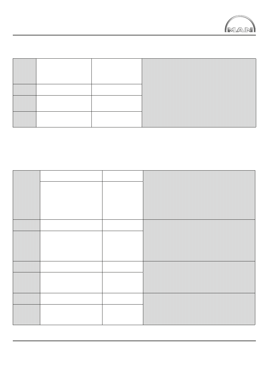
Each of the speed and brake lining wear sensors itemised in Table 5 below are plugged into the corresponding EBS pressure control
module on the rear axles. The associated cabling does not need to be extended when extending the wheelbase because the pressure
control module is moved together with the rear axle. For reasons of completeness and for special designs, extension wiring harnesses
for speed and brake lining wear sensors are nevertheless available.
Table 5:
Wiring harness extensions for special cases
TGA
TGL TGM
Speed sensor, drive axle
left B121
81.25453.6377
1 x 2-pin
Unplug 2-pin connector (grey BA20 left, black BA21
right)from pressure control module on rear axle. Dismantle
catch (GV10), eject contacts and push in a new housing with
identical pin socket collar (BA70 left, BA71 right). Replace
catch (GV10). Connect corrugated pipe and connector
(BA70/BA71) using adapter 81.25433.0184 (AW 64) (e.g.
SS1).Alternatively: Attach existing housing and wiring
harness extension with shrinkdown plastic tube (e.g. SS1)
to corrugated pipe.
Speed sensor, drive axle
right B122
81.25453.6378
1 x 2-pin
TGA
TGL TGM
Brake lining sensor B335,
drive axle 2, rear left
81.25453.6387
1 x 4-pin
Unplug 4-pin connector (black BA72 left, orange BB70 right)
from EBS pressure control module on rear axle. Connect
corrugated pipe and connector with adapter (AW64) and
extend brake lining sensor with extension81.25453.6387 left
/ 81.25453.6388 right.Insert connector of extension
(black left, orange right) intoEBS pressure control module
on rear axle.
TGA
TGL TGM
Brake lining sensor B334,
right drive axle
Applies to drive axle on
4x2,6x2/2, 6x2-4, 6x2/4, rear
drive axle on 4x4 and rear axle 1
for all other wheel formulae
81.25453.6388
1 x 4-pin
TGA
TGL TGM
Brake lining sensor B335,
left drive axle
81.25453.6387
1 x 4-pin
Unplug 4-pin connector (black BA72 left, orange BB70right)
from BVS distributor (brake lining wear sensor, left X2431,
right X2432) and insert extension 81.25453.6387 left /
81.25453.6388right in between.
TGA
TGL TGM
Brake lining sensor B334,
right drive axle
Applies to drive axle 2 rear right
on 6x4, 6x6, 8x4, 8x6 and 8x8
81.25453.6388
1 x 4-pin
TGA
(TGL TGM)
Brake lining sensor B530,
left rear additional axle
81.25453.6385
1 x 4-pin
Unplug 4-pin connector (green BB69 left, grey BB68 right)
from distributor BVS (brake lining wear sensor, left X2431,
right X2432) and insert extension 81.25453.6385 left
/81.25453.6386 right in between. As at: 5-2006:Additional
axles are in planning for TGL and TGM.
TGA
(TGL TGM)
Brake lining sensor B529,
right rear additional axle
Applies to leading/trailing axle on
6x2/2, 6x2-4, 6x2/4
81.25453.6386
1 x 4-pin
Interfaces TG 4
2.
Wiring harness for tail lights, additional tail lights, trailer tow sockets, side marker lights
and additional ABS sockets
The possible applications for these cable extensions are:
•
Wiring harness extension for tail lights and trailer tow sockets as a result of extending the overhang
•
Connection of additional tail lights via T-distributor
•
Connection of additional sockets via T-distributor – potential applications: Mounting of 15-pin and type 24N/24S 7-pin
sockets or mounting of sockets behind cab on tractor units and trailer tow sockets on the frame end.
•
Wiring harness extensions for side marker lights
To extend wiring harnesses or fit additional lights/sockets, only the wiring harnesses described here may be used so as to ensure
the correct functioning of the CAN data network.
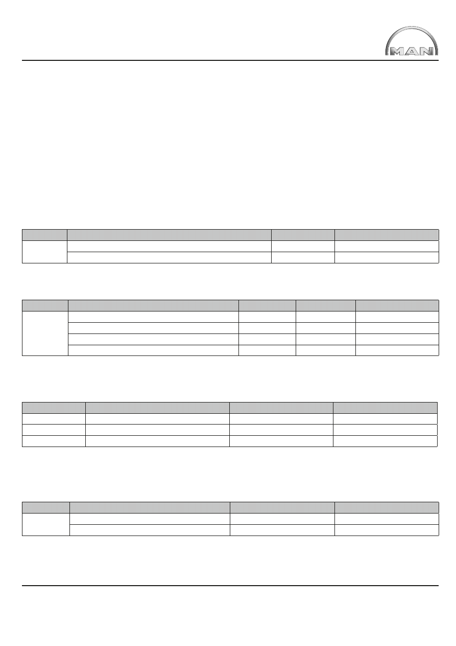
Table 6:
Extension cable wiring harness, tail lights
Range
Designation
Length in meters
MAN item number
TGA
TGL TGM
Extension wiring harness for tail lights (per light)
1
81.25428.6975
Extension wiring harness for tail lights (per light)
1,5
81.25428.6982
Table 7:
Extension wiring harness, trailer tow sockets
Range
Designation
Plug color
Length in meters
MAN item number
TGA
TGL TGM
Extension wiring harness for trailer tow socket
black
1
81.25428.6971
Extension wiring harness for trailer tow socket
black
1,5
81.25428.6972
Extension wiring harness for trailer tow socket
brown
1
81.25428.6973
Extension wiring harness for trailer tow socket
brown
1,5
81.25428.6974
Pin assignment depends on the plug colour of the wiring harness:
Table 8:
Assignment of socket to plug colour of the cable
Socket
Application
Standard
Plug
Typ 24 N
24 V 7-pin N=normal
DIN ISO 1185
1 x black
Typ 24 S
24 V 7-pin S=supplementary
DIN ISO 3731
1 x brown
15 pin
24 V 15-pin
DIN ISO 12098
1 x black + 1 x brown
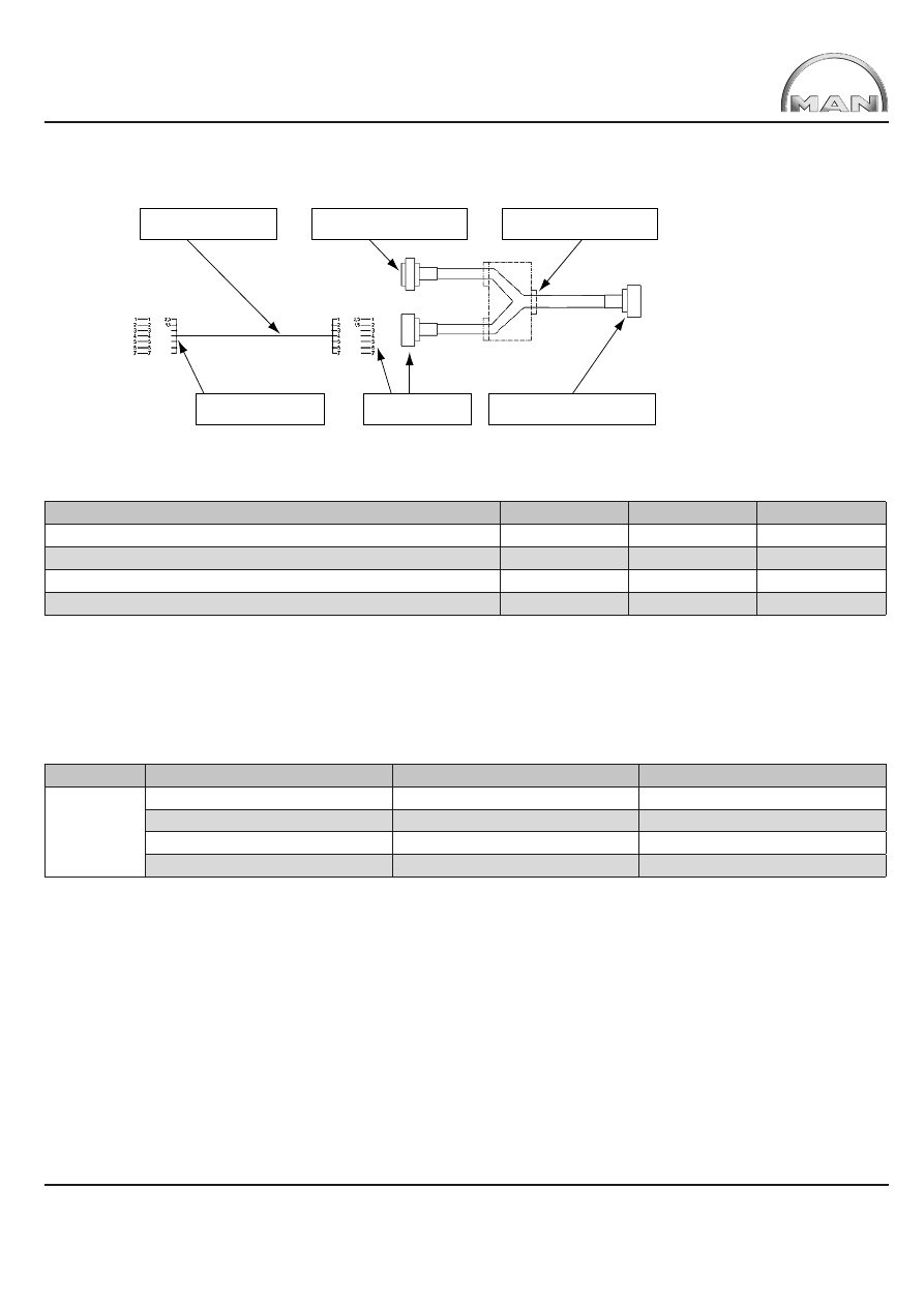
Adapter wiring harnesses for tail lights and trailer tow sockets are available for fitting additional lights and sockets (T-distributor).
The operating principle is shown in Figure 1.
Table 9:
Adapter wiring harness (T-distributor) for additional tail lights
Range
Designation
Length in meters
MAN item number
TGA
TGL TGM
Adapter wiring harness for tail lights
1,1
81.25432.6164
Adapter wiring harness for tail lights
1,6
81.25432.6165
Interfaces TG 5
Extension wiring harness
for tail lights
Plug-in to additional
tail lights
Plug cables together
Plug-in to standard
tail lights
Adapter wiring harness
(t-distributor) for tail lights here
Plug-in existing connector
cable fot tail lights here
Fig. 1:
Operating principle of T-distributor (example: additional lights)
Table 10:
Adapter wiring harness (T-distributor) for additional trailer sockets
Adapter wiring harness (T-distributor) for additional trailer tow sockets
Plug colour
Length in meters
MAN item number
Adapter wiring harness, symmetrical T-piece
black
Approx. 0,25
81.25432.6157
Adapter wiring harness, symmetrical T-piece
brown
Approx. 0,25
81.25432.6160
Adapter wiring harness, asymmetrical T-piece
black
Approx. 0,7
81.25432.6173
Adapter wiring harness, asymmetrical T-piece
brown
Approx. 0,7
81.25432.6174
Depending upon the body design it may also be necessary to reposition the side marker lights (the statutory regulations applicable to
the lighting system must be observed). If the connection cables are too short, various lengths of wiring harness extension are available.
Only original MAN side marker lights using LED technology are permitted. Use of any other lights will result in the partial operating
permit for the lighting system to become invalid. Side marker lights with incandescent bulbs will damage the ZBR.
Table 11:
Extensions for side marker lights
Range
Designation
Length in meters
MAN item number
TGA
TGL TGM
Wiring harness extension
0,5
81.25417.6685
Wiring harness extension
1,0
81.25417.6686
Wiring harness extension
2,0
81.25429.6294
Wiring harness extension
3,0
81.25429.6295
An adapter wiring harness also enables individual cables to be tapped (e.g. to connect an additional license plate light).
Individual connector plugs with individual cables are to be made up using Seal connectors, Figure 2 shows how to make up
an individual connector plug.
Interfaces TG 6
Depending on the number of leads, use
corrugated hose size 10,04.37135-9940,
or size 8,5,04.37135-9938, in
appropriate length
Secondary locking
81.25475-0105
7-pin connection plug
81.25475-0105
Contact for lead cross-section from 0,5
2
to 1
2
07.91216-1226
Contact for lead cross-section from 0,5
2
to 2,5
2
07.91216-1228
Blind seal 07.911630051
for connection plug
chambers in which there
are no leads
Single core seal for lead cross-section from 0,5
2
to 1
2
07.91163-0052
Single core seal for lead cross-section from 0,5
2
to 2,5
2
07.91163-0053
Fig. 2:
Making up an individual connector plug
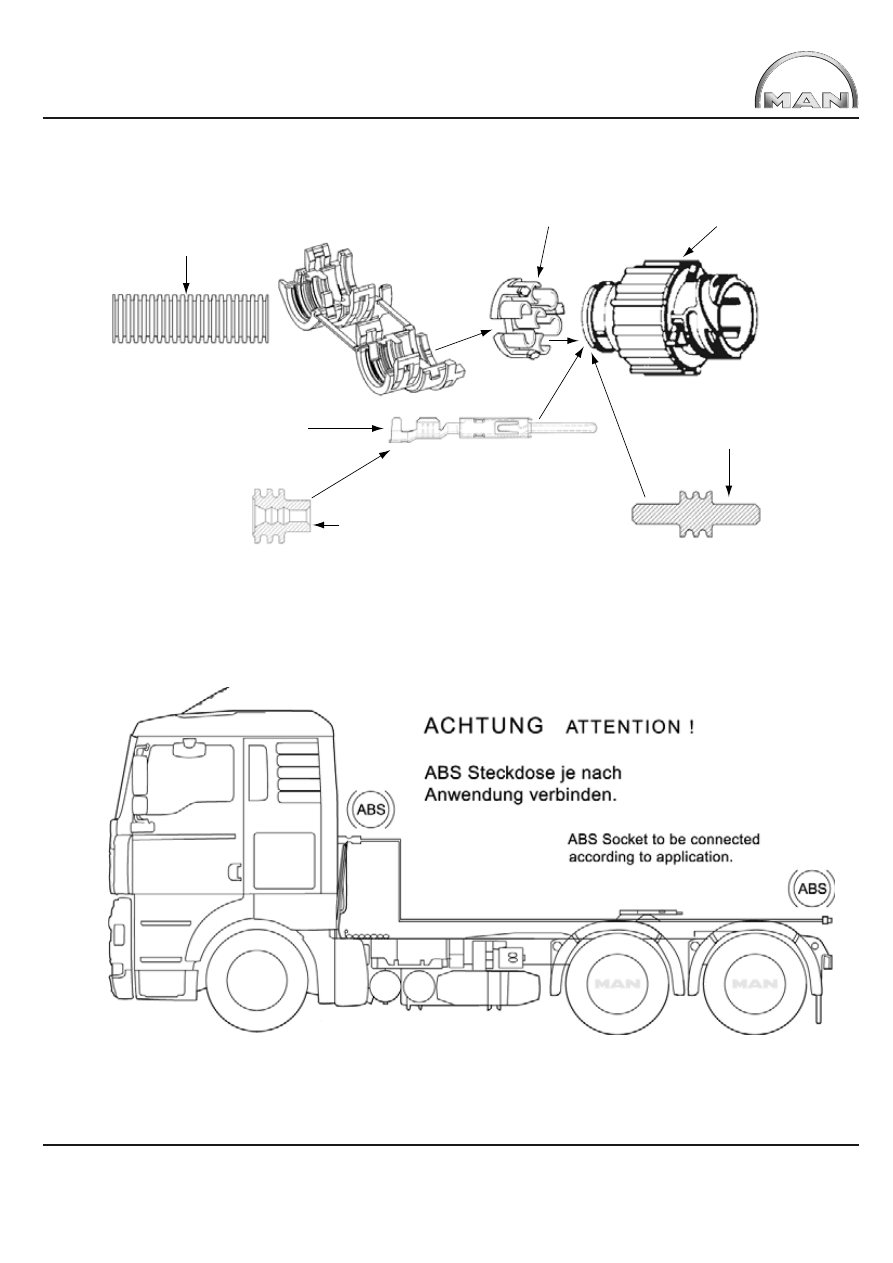
Additional ABS sockets are available for alternating use as a socket behind the cab on tractor units and trailer sockets at
the frame end. However, this does not function with T-distributors but with an extension cable, see Figure 3.
Fig. 3:
Use of ABS-extension cable
In this way the ABS socket may be mounted either behind the cab (tractor unit) or at the frame end (truck).
The cable lengths available conform with the wheelbases of the respective MAN tractor unit (see Table 12).

Interfaces TG 7
Table 12:
ABS extension cables
Item no.
81.25453.6288
81.25453.6290
81.25453.6291
81.25453.6292
Cable length (total)
4.700mm
5.400mm
6.100mm
6.800mm
Application
Wheelbase R
Tractor unit 4x2, 4x4
R <= 3.900
Tractor unit 6x2
R <= 3.200+1.350
Tractor unit 6x4, 6x6
R <=3.600+1.350
Tractor unit 6x4, 6x6
R <= 3.600+1.350
3. Tapping the speed signal
Caution!
In order to avoid control unit error messages always switch off the ignition prior to carrying out any work
on
the
tachograph!
It is possible to tap the speed signal from the tachograph. This will ensure that the load on the corresponding pin does not exceed
1mA! This is generally equates to the equivalent of two connected peripheral units. Should this option for tapping the signal be
inadequate then the following output multipliers bearing the MAN codes can be connected:
81.25311-0022 (3 • v-pulse output, max. load 1mA for each output) or
88.27120-0003 (5 • v-pulse output, max. load 1mA for each output).
Option for tapping the ‘B7 signal’ = speed signal:
1)
At connector B / Pin 7 on the back of the tachograph
2)
At the 8-pole plug connection X1536 / contact 5. The plug connection is located behind a cover on the driver side A-pillar
in the area around the driver’s footwell.
3)
At the factory-fitted interface with customer-specifi c control module from STEP1 (see Chapter 4.3)
4. Interfaces for intermediate speed control
4.1 Abbreviations and terms used
The text below and the detailed description of the interfaces contains several abbreviations and MAN-specifi c terms,
which Table 13 explains in alphabetical order.

Interfaces TG 8
Table 13:
Abbreviations used and MAN-specifi c terms
Term/abbreviation
Explanation
A-CAN
Set-up-CAN (CAN = Controller Area Network)
AUS
Switch-off of FGR/FGB/ZDR functions
CAN
Controller Area Network (= databus, digital network)
DBG
Engine speed limiter
DE
Digital input
EMV
Electromagnetic compatibility
FIN
Vehicle identifi cation number
FFR
Vehicle management computer
FGR/FGB/ZDR
Vehicle speed control/vehicle speed limiter/intermediate speed control
FMS
Fleet Management System
GETRIEBE-N
Neutral position of gearbox
GMT
Greenwich Mean Time
HGB
Maximum speed limiter
High-side-Schalter
Output switching downstream of Terminal 30 (+U
BAT
)
HP
ZF automatic gearbox HP...
KS
Short circuit
KSM
Customer-specifi c control module
LED
Light emitting diode
Low-side-Schalter
Output switching downstream of Terminal 31 (-U
BAT
)
M3135
MAN works number (M+Number 3 - 4 digit)
MAN-CATS II
Computer diagnostic system used in MAN workshops (CATS = computer aided testing system)
MBG
Torque limiter
MDB
Torque/speed limiter
MEMORY
Stored function/value
NA
Power take-off
NMV
Power take-off prefitted depending on engine
PIN
Plug contact
PTO
Power take off
PWM
Pulse width modulation
R-Gang
Reverse gear
SET+
Increase and set speed and/or accelerate
SET-
Reduce and set speed and/or decelerate
SG
Control unit
T-CAN
Power train-CAN (CAN = Controller Area Network)
+U
BAT
Pulse voltage of batteries
-U
BAT
Minus voltage of batteries
UTC
Universal Time Code
VIN
Vehicle Identifi cation Number
ZBR
Central on-board computer
ZDR
Interim speed control/regulator
Interfaces TG 9
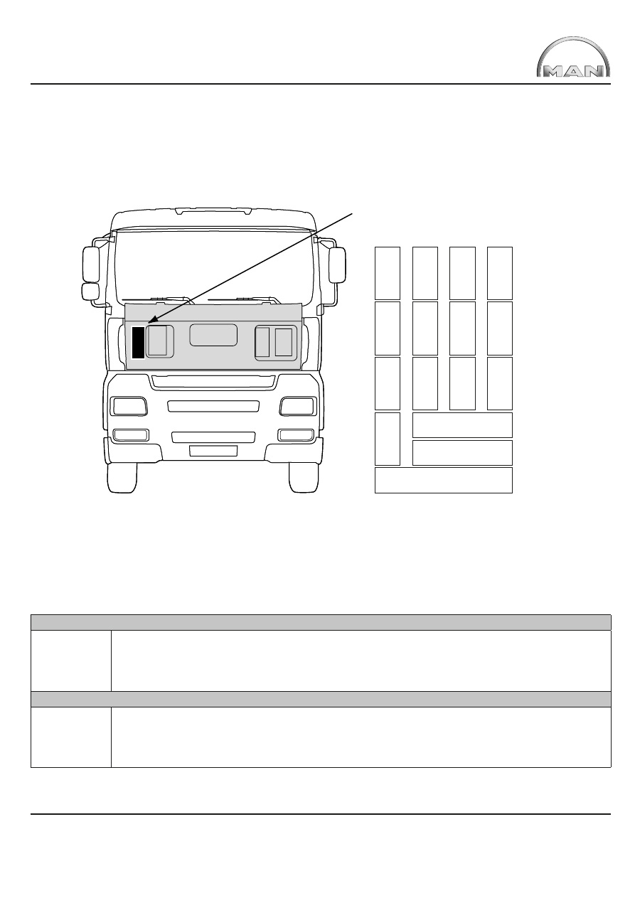
View after cover is removed:
ZDR-Inter-
face (FFR)
X1996/18-pin
XXX
XXX
XXX
ZDR-Inter-
face (KSM)
X1997/18-pin
4.2
Interface mounting location
The ZDR interfaces are located behind the front panel and can be accessed from outside after unlocking the front panel and removing
the housing cover (see Figure 4).
Fig. 4:
Mounting location of ZDR-interfaces
4.3
Description
The retrofit KSM interface is available in 2 versions to-date and these are both upwards compatible (fitting new version in a used
vehicle) and downwards compatible (fitting new version in used vehicle and older version can be fitted into new vehicle).
The fleet management interface can only be fitted together with the KSM interface STEP05 or later (fitted ex-works since March 2002).
Table14:
Interface descriptions
Intermediate speed control with interface on vehicle management computer (ZDR on FFR)
download
PDF-File:
zdr-ffr_gb.pdf
This document describes the interface for intermediate speed control on the vehicle management computer (FFR),
the interface is fitted on all TG chassis and tractor units. It is however, only enabled if either intermediate speeds, a
power take-off with intermediate speeds or a power take-off preparation has been ordered ex-works. Retrospective
enabling or disabling of the interface is possible in authorised workshops. The general and industry-specific factory
settings for the interface have been circulated to all MAN workshops via a service bulletin.
Intermediate speed control with customer-specific control module (ZDR with KSM) STEP0 (fitted ex-works to March 2002)
download
PDF-File:
zdr-ksm_gb.pdf
This document describes the interface on the customer-specific control module, the interface is available as
a special equipment item for all TG. It is possible to retrofit the interface and modify its functions in authorised
workshops. This version of the interface does not support the manufacturer-independent Fleet Management
Standard (FMS). For the FMS interface, a KSM of generation STEP05 or later is required
(= Item no. 81.25806.7004).
Interfaces TG 10
Table14:
Interface descriptions
Intermediate speed control with customer-specific control module (ZDR with KSM) STEP05
(fitted ex-works since March 2002 = 81.25816.7004)
download
PDF-File:
(zdr-ksmstep05-
fms_gb.pdf)
This document describes the interface for the customer-specific control module of Generation Step 05,
recognisable by Item No. 81.25816.7004 affi xed to the housing. This interface is available as a special equipment
item for all TG vehicles. It is possible to retrofit the interface and modify its functions in authorised workshops.
Fleet management standard interface with customer-specific control module (FMS with KSM) STEP05
(fitted ex-works since March 2002 = 81.25816.7004)
download
PDF-File:
(zdr-ksmstep05-
fms_gb.pdf)
This document describes the implementation of the manufacturer-independent Fleet Management Standard
Interface (FMS) for all TG vehicles. Additional information is available at www.fms-standard.com. The FMS
interface is integrated into customer-specific control modules (= KSM) Step05 and later (= item number
81.25816.7004) and this is the reason why this special equipment item is a pre-requisite for connection to the
FMS interface. It is possible to retrofit the interface and modify its functions in authorised workshops.
Intermediate speed control with customer-specific control module (ZDR with KSM) STEP 1
(fitted ex-works since August 2003 = 81.25816.7005)
download
PDF-File:
zdr-ksmstep1-
fms_gb.pdf
This document describes the interface for the customer-specific control module of Generation Step 1,
recognisable by Item No. 81.25816.7005 affixed to the housing. This interface is available as a special item for all
TG vehicles. It is possible to retrofit the interface and modify its functions in authorised workshops.*
* Requires a central on-board computer with code ZBR 81.25806.7033 or higher item number and vehicle
management computer FFR 81.25805.7015.
Fleet management standard interface with customer-specific control module (FMS with KMS) STEP 1
(fitted ex-works since August 2003 = 81.25816.7005)
download
PDF-File:
zdr-ksmstep1-
fms_gb.pdf
This document describes the implementation of the manufacturer-independent Fleet Management Standard
Interface (FMS) for all TG vehicles. Additional information is available at www.fms-standard.com. The FMS-
interface is integrated into the customer-specific control module (= KSM) STEP05 and later (= item number
81.25816.7005), which is why this special equipment item is a pre-requisite for connection to the FMS interface.
It is possible to retrofit the interface and modify its functions in authorised workshops.*
* Requires a central on-board computer with code ZBR 81.25806.7033 or higher item number and vehicle
management computer FFR 81.25805.7015.
Wyszukiwarka
Podobne podstrony:
MAN TG 510 A
MAN Elektrycznee i elektroniczne złącza TG(1)
MAN Mechanizmy sprzęgowe TG(1)
MAN TG 510 A
7000DELUXE INTERFUNK
Interfejsy
400 man
man ar900
5 interferometria id 40157 Nieznany (2)
Przegląd układu tłokowo – korbowego silnika MAN B&W – L 2330 H
Instrukcja obsługi interfejs KKL OPEL, BMW, VAG
Do czego przydaje się interferencja
więcej podobnych podstron