
POSITIONER 1067
E-1- Ref. 420832
Fluid Control Systems
TABLE OF CONTENTS
1
INTRODUCTION ................................................................................................................ E-2
1.1
Unpacking and inspecting .................................................................................................. E-2
1.2
General notes on use and safety ....................................................................................... E-2
1.3
Electromagnetic compatibility ............................................................................................ E-2
2
DESCRIPTION ................................................................................................................... E-3
2.1
Characteristics and possible applications ......................................................................... E-3
2.2
Construction ....................................................................................................................... E-5
2.3
Principle of operation ......................................................................................................... E-6
2.4
Safety position .................................................................................................................... E-7
2.5
Technical data .................................................................................................................... E-8
3
INSTALLATION ................................................................................................................. E-9
3.1
Construction and assembly ................................................................................................ E-9
3.1.1 Fitting the positioner to a continuous valve with membrane drive (NAMUR) .......... E-9
3.1.2 Fitting the positioner to a 2031 continuous valve with piston drive ....................... E-11
3.1.3 Fitting the positioner to a continuous valve with rotary drive ................................. E-13
3.2
Fluid ports ......................................................................................................................... E-14
3.3
Electrical connections ...................................................................................................... E-15
4
OPERATION .................................................................................................................... E-16
4.1
Controls and indicators .................................................................................................... E-16
4.2
Operating levels ............................................................................................................... E-16
4.3
Setting up ......................................................................................................................... E-17
4.4
Process control ................................................................................................................. E-19
4.4.1 Meaning of LEDs and keys in the process control level ........................................ E-19
4.4.2 Displays ................................................................................................................... E-19
4.5
Configuration .................................................................................................................... E-21
4.5.1 Additional functions ................................................................................................. E-21
4.5.2 Configuration menu ................................................................................................. E-23
4.5.3 Function of keys in the configuration level ............................................................. E-25
4.5.4 Notes on the basic and additional functions .......................................................... E-25
4.6
Manual operation without power supply .......................................................................... E-34
4.7
Structure of the positioner ................................................................................................ E-35
5
MAINTENANCE ............................................................................................................... E-36
Fault messages ................................................................................................................ E-36
APPENDIX ....................................................................................................................... E-37
A1: Characteristics of PID controllers .............................................................................. E-37
A2: Rules for adjusting PID controllers ............................................................................ E-41
A3: Optional board for analog position indication ............................................................ E-44
A4: Optional board for binary position indication/Booster ............................................... E-45
A5: Examples of EASY LINKS with the positioner 1067 ................................................. E-47

E-2-
POSITIONER 1067
Fluid Control Systems
1 INTRODUCTION
Dear Customer,
We congratulate you on the purchase of our
positioner 1067. You have made a good choice.
To be able to make the best use of the many
advantages the product has to offer, it is
absolutely necessary to follow our advice and
READ THESE OPERATING INSTRUC-
TIONS CAREFULLY BEFORE FITTING
THE UNIT AND PUTTING IT INTO
SERVICE
1.1 Unpacking and inspecting
Please check the delivery for completeness and
transportation damage. The standard delivery
includes:
-1 Positioner 1067 Ref 642292
-1 Operating Instructions Manual
In the event of loss or damage please contact
your Bürkert Subsidiary.
1.2 General notes on use and
safety
This publication contains no warranty statement
For this we refer to our general purchase and
delivery conditions.
To ensure proper functioning and a long life of
the positioner, the user must observe these
Operating Instructions as well as complying with
the installation conditions and permissible data
as given in the data sheet. Installation and
maintenance personnel must have training and
qualifications suitable for the task.
Suitable measures are to be taken to prevent
unintentional actuation and the resulting effect
on the process. Safe electrical isolating and shut-
off devices for the media must be provided for
the installation task. If the positioner is part of a
complex automated system, a defined and
controlled restart of the automated system after
an interruption shall be guaranteed in accordance
with the instructions.
The accident and prevention safety regulations
for electrical equipment shall be complied with
during the operation, servicing and repair of the
positioner.
Repairs may only be carried out by authorised
trained personnel.
This symbol is shown in the Operating
Instructions each time particular care
is required to ensure correct
installation, functioning and operating
safety of the equipment.
1.3 Electromagnetic compatibility
This device conforms to the EMC-Directive of
the Council of European Communities
89/336/EEC.
In order to comply with this directive, the wiring
instructions must be followed.
Master code
Unauthorised operation can be prevented at the
various operating levels by a freely-selectable
user code. Independent of this, there is a fixed,
programmed master code which cannot be
changed, by means of which all operations can
be performed.
This four-digit master code is
given on the bottom margin of this page. It
can be cut out and kept separately from these
Operating Instructions.
Master code:
6568
!

POSITIONER 1067
E-3-
Fluid Control Systems
2 DESCRIPTION
2.1
Characteristics and possible applications (overview)
The 1067 positioner is an electropneumatic position controller for pneumatically actuated continuous
valves. The device includes the following main functional groups: a feedback/positional transducer,
an electropneumatic system and a microprocessor electronic system. The feedback/positional
transducer measures the actual position of the continuous valve. The microprocessor electronic
system continuously compares the actual position (actual value) with a desired position value that
was preset via the standard signal input and supplies the result to the position controller. If an error
exists, the electropneumatic system causes the actual position to be appropriately corrected.
The 1067 positioner can be fitted to various continuous valves (e.g. valves with piston, membrane
or rotary drives and with single or double action). Two variant forms of the basic device are offered
that differ in their fixing options and feedback/positional transducers. In variant 1, an internal feedback/
positional transducer is used that takes the form of a rotary potentiometer. In variant 2, an external
linear potentiometer serves as feedback/positional transducer.
The positioner also implements a PID controller by means of which, in addition to position control,
process control (e.g. level, pressure, flow or temperature control) can be achieved in the form of
sequence control.
A liquid-crystal display and a keypad with three keys are provided for operating the positioner. An
operating concept with the following graded operating levels has been implemented:
- Process operation
This level allows switching between automatic and manual operation, and enables manual actuation.
- Configuration
Configuration level is used to specify certain basic functions when the positioner is taken into service
and, if necessary, to configure additional functions.
E-4-
POSITIONER 1067
Fluid Control Systems
2 DESCRIPTION
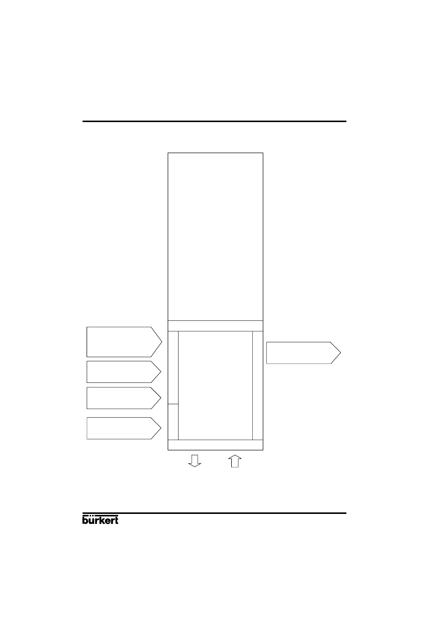
Fig. 1
Block diagram of the 1067 positioner
Positioner
1067
Input for process actual
value
4...20 mA
Input for position or
process setpoint
0...10 V
0...20 mA
4...20 mA
24 VDC
Binary input (contact)
Analog output (option)
Operation
Characteristics, functions
In
p
u
ts
P
o
w
e
r
O
u
tp
u
t
Position controller with
additional functions, e. g.
- close tight function
- plug travel limitation
- setting speed limitation
- split range
- correction characteristics
- deadband
- safety position
Additional integrated process
controller with the following features:
- adjustable parameters
- scalable inputs
- setpoint setting via input signal or
keys
Automatic adaptation of position
controller to the continuous valve in
use
Hierarchical operating concept for
simple, staged-level operation
POSITIONER 1067
E-5-
Fluid Control Systems
2 DESCRIPTION
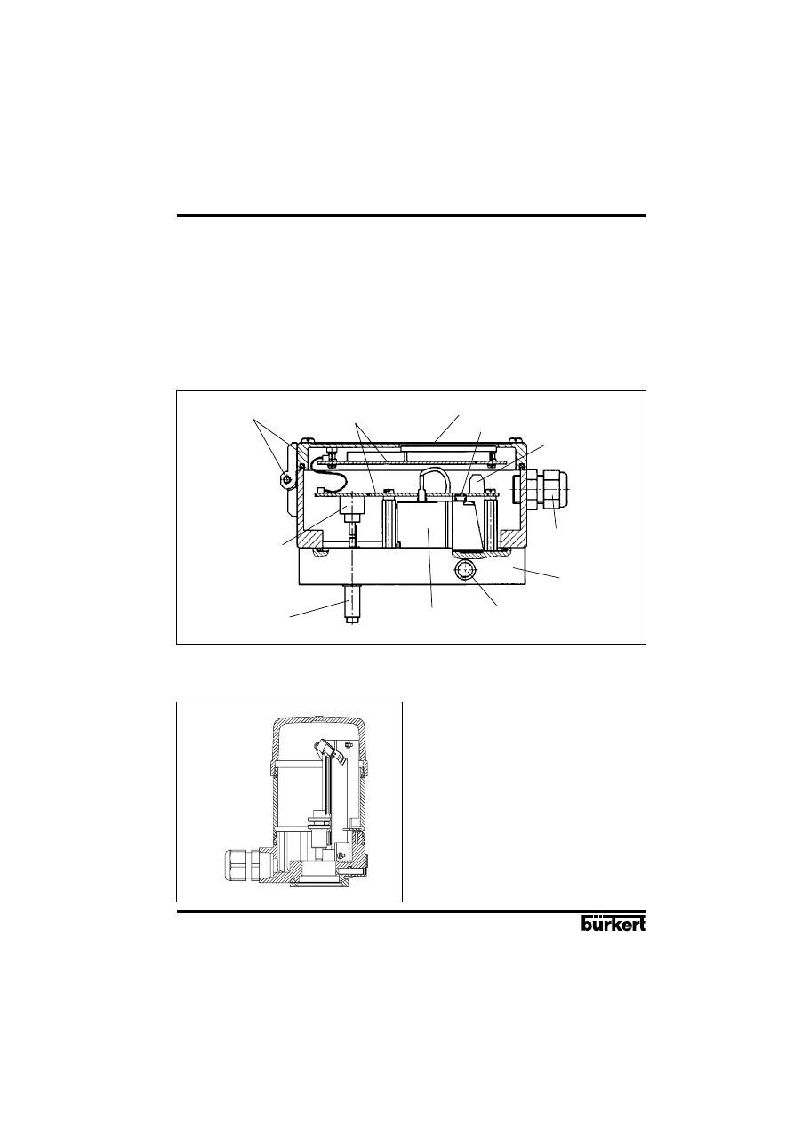
2.2 Construction
The positioner consists of the following main assemblies:
- Body and bonnet (aluminium)
- internal feedback/positional transducer for measuring valve position
- Microprocessor/electronic unit for signal processing and control
- Solenoid valves for control of a continuous action valve
- Fluid plate with fluid ports
- Terminals and cable glands
- Display and keyboard
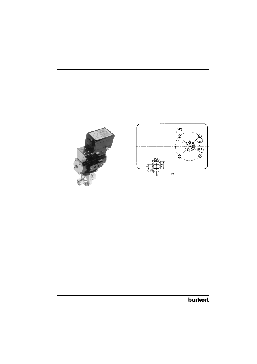
Fig. 2
Cross section of the positioner with internal feedback/positional transducer
Connection
terminal
Manual operation
Cable gland
Display and keypad
Fluid plate
Fluid ports
Solenoid valve
Aluminium body and
bonnet with hinge
Electronic
In variant 2, an external linear potentiometer serves as feedback/positional transducer (see fig. 3).
Fig. 3
External feedback/positional transducer
Positional
transducer shaft
Internal feedback/
positional transducer for
connection according to
NAMUR
E-6-
POSITIONER 1067
Fluid Control Systems
2 DESCRIPTION
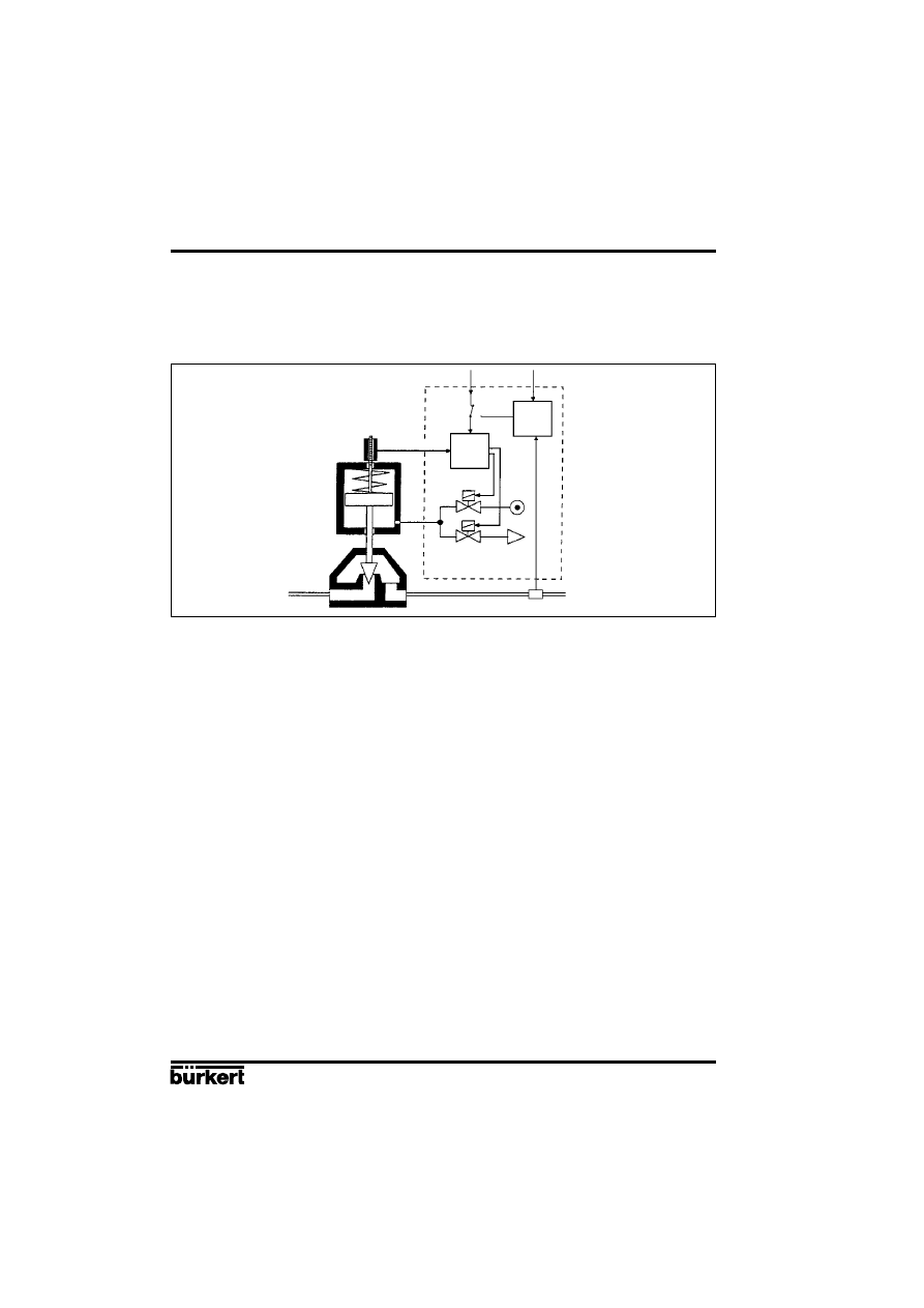
2.3 Principle of operation
Fig. 4 shows a operational diagram of the positioner with its relationship to a piston drive control valve.
An external feedback/positional transducer is used in this case to measure the actual position.
Fig. 4
Operational diagram
Piston
valve
Air inlet
Solenoid valves
Air exhaust
Position
controller
Set
position
Process value (Pressure, flow, level...)
Sensor
Process
controller
The position (actual position) of the valve drive is determined by the feedback/positional transducer.
The signal corresponding to the actual position is continuously compared in the positioner with the
desired position and the error (control deviation) is formed. Pulses of variable duration corresponding
to the error are delivered to the magnetic valves of the electropneumatic system, by means of which
the supplied air and outgoing air for positioning the actuating drive of a continuous valve are controlled.
The desired position can be preset either via a standard signal input from outside (e.g. manually or
via an external controller) or via the internal process controller. In the latter case, the desired process
value is applied to the standard signal input or entered via keypad and a comparison is made with
the process quantity (e.g. flow, pressure, level or temperature) that is to be controlled (Fig. 4).
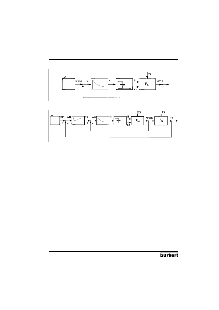
If the desired position is preset externally via the standard signal input provided for that purpose (i.e.
if the internal process controller is not used), the device works as a position controller only (Fig. 5).
The position controller is implemented as a PD controller within the microprocessor. A pulse-width
modulation (PWM) member is connected to the controller output and, via its B
1
and E
1
outputs, the
magnetic valves for supplying air to and venting the actuating drive are controlled. When a positive
error exists, pulses (PWM signals) are output from output B
1
to switch the supplied air. When a
negative error exists, pulses are output from output E
1
to switch the outgoing air.
The positioner can be supplied for both single-acting and double-acting actuating drives. The PWM
member has two further outputs, B
2
and E
2
, via which the two additional magnetic valves for supplying
air to and evacuating air from double-acting actuating drives are controlled.
If the internal process controller is used, it constitutes a component in a higher-level control loop
(main control loop). The position controller mentioned above now operates in a lower-level auxiliary
control loop. The overall effect is sequence control (Fig. 6). The internal process controller (main
controller) is implemented as a PID controller (Z1 and Z2 representing disturbance variables).
Feedback/positional
transducer
Actual-position
External setpoint
Process
setpoint
POSITIONER 1067
E-7-
Fluid Control Systems
2 DESCRIPTION
Fig. 5
Position control
Position controller
Valve actuator
PWM element
Setposition
Fig. 6
Process control
Process
Auxiliary control loop
Main control loop
Set
position
2.4 Safety position
In the event of power failure, the functioning of the actuator ensures that a pre-determined end
position is adopted (opened or closed by spring pressure).
Process
controller
Position controller PWM-element
Valve actuator

E-8-
POSITIONER 1067
Fluid Control Systems
2 DESCRIPTION
2.5 Technical data
Electrical data
Power supply:
24 VDC
Power consumption:
< 10 W
Input for desired value
Input for setpoint for position or process control:
- Unit signal
4 ... 20 mA
- Unit signal
0 ... 20 mA
- Unit signal
0 ... 10 V
Input for process signal (in case of process control):
- Unit signal
4 ... 20 mA
Binary input:
Can be configured as a normally open or normally
closed contact.
Terminations:
1.5 mm
2
bolted terminals
Two PG 9 screwed glands
Pneumatic data
Control medium:
filtered compressed dry air, oiled or non-oiled
Pressure range:
0 ... 6 bar
Air rates
Inlet valve:
23 Nl / min
(1)
Exhaust valve:
25 Nl / min
(1)
Air consumption by unit
in stable state:
0 Nl / min
Unions:
G 1/8" internal thread
(1)
When pressure reduction from 6 to 5 bar
Mechanical data
Regulation range of internal path-measuring system:
lift turn: 10...80 mm
rotary movement: 0...180
°
Regulation range of external path-measuring system:
lift turn: 0...50 mm
Process controller data
Proportional correction value KP:
0...99,99
Reset time TN:
0.5...999.9
Rate time TV:
0.0...999.9
Operating point:
0...100%
Installation and operating data
External dimensions of positioner :
125 mm x 80 mm x 80 mm (W x H x D)
Material of body:
Aluminium, lacquered
Material of the fluid plate:
Aluminium, anodised
Weight of positioner:
Approx. 1 kg
Degree of protection:
IP 65
Operating temperature:
0 ... 60
°C
POSITIONER 1067
E-9-
Fluid Control Systems
3 INSTALLATION
3.1 Construction and assembly
The 1067 positioner can be fitted to various continuous valves. Depending on the valve type either
variant 1, with an internal feedback/positional transducer (a rotary potentiometer) or variant 2, with
an external feedback/positional transducer (a linear potentiometer) is used (see section 2.3).
Main dimensions:
Positioner
External feedback/positional transducer
Width:
125 mm
Diameter:
approx. 65 mm
Height:
80 mm
Height:
approx. 95 (115) mm
Depth:
80 mm
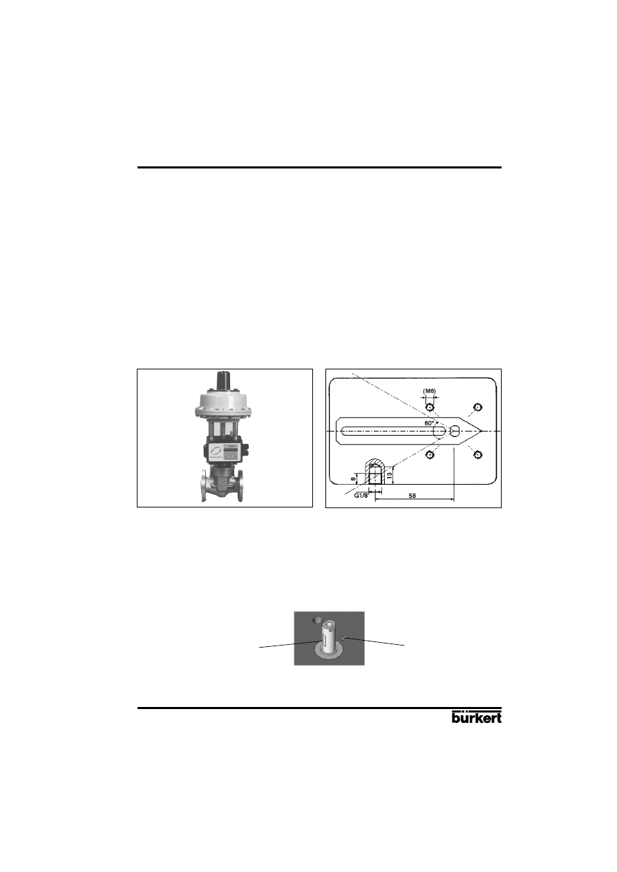
3.1.1 Fitting the positioner to a continuous valve with membrane drive (according to NAMUR)
Arrangement
In the case of a continuous valve with membrane drive, device variant 1, with an internal feedback/
positional transducer (a rotary potentiometer) should be used. The positioner is screwed on to what
is termed the «lantern» of the membrane drive (Fig. 7). Transmission of the valve position to the
internal feedback/positional transducer is achieved by means of a lever conforming to NAMUR
(Fig. 8).
Assembly
A mounting elbow (Fig. 10) is provided for assembling variant 1 of the positioner to a continuous valve
with membrane drive (e.g. 265). The following steps should be carried out:
Screw mounting elbow to the positioner using 4 x M6 screws.
Fasten pin using washer and nut to that position of the lever which corresponds with the
desired lift (the lever is marked in mm of lift).
To avoid a TURN POT error (dead zone of the path-sensor), position the shaft of the path-sensor of
the positioner so that during the whole lift of the actuator the flattened part never passes in front of
the yellow mark (see following picture).
Put lever with pin on to the path-sensor shaft. Then screw lever tight with screw . Fasten carrier
with cheese-head bolts to the lifting rod of the membrane valve.
Fig. 7
Fitting to a 265 continuous valve with
membrane drive
Fig. 8
Rear view of positioner (variant 1) with
lever
Flattened part on the shaft
of the path-sensor
yellow mark
E-10-
POSITIONER 1067
Fluid Control Systems
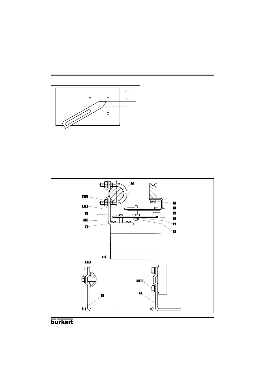
Fig. 9
Position of lever during assembly
3 INSTALLATION
Set positioner, with the mounting elbow screwed on to it, on the membrane drive so that the pin
slots into the carrier , the point of the lever runs parallel with the upper edge of the positioner
(Fig. 9) and the rear side of the positioner runs parallel with the carrier . Fasten the positioner to
the membrane drive in this position as appropriate to the following variants:
- In the case of membrane drives with pillar lanterns, fasten mounting elbow with two U-bolts ,
nuts and washers to the appropriate pillar lantern (Fig. 10a).
- In the case of membrane drives with cast lanterns, fasten mounting elbow with one screw
(Fig. 10b) or four screws (Fig. 10c) to the appropriate cast lantern (Fig. 10a).
Fig. 10
Assembly of positioner to a continuous valve with membrane drive
Parallel
POSITIONER 1067
E-11-
Fluid Control Systems
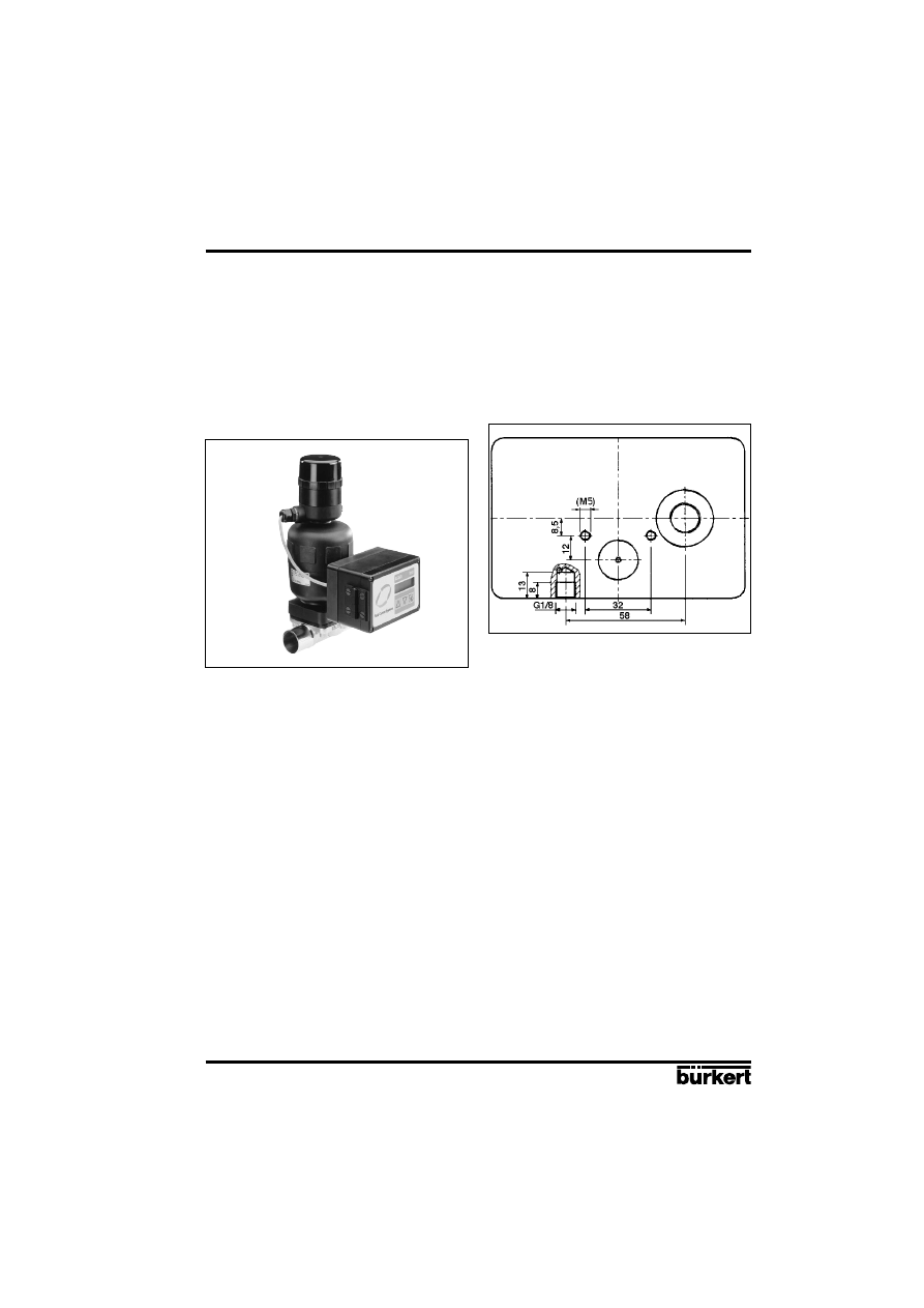
Fig. 11
Fitting to a 2031 continuous valve
with piston drive
Fig. 12
Rear view of positioner (variant 2)
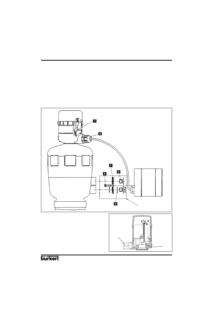
Assembly
Assembly of variant 2 of the positioner to a 2031 continuous valve with piston drive.
A set of add-on parts (NAMUR adapter, Fig. 13) is provided for assembling variant 2 of the positioner
to a piston valve (e.g. 2031). It consists of a mounting plate , two hollow bolts , three O-rings
and two cheese-head bolts M5 .
To assemble the positioner on a 2031 continuous valve with piston drive, the following steps should
be carried out (Fig. 13):
Place an O-ring in the recess of the mounting plate (drive side). In the case of a large version,
place a second O-ring on the other side of the mounting plate.
Put two cheese-head bolts M5 from the drive side through the 5-mm drillings in the mounting plate.
Screw the preassembled mounting plate to the two connection pieces of the valve drive with two
hollow bolts so that the lower connection piece is sealed by the O-ring.
Place an O-ring in the groove on the reverse side of the positioner.
Add the positioner to the mounting plate and screw it on with the two cheese-head bolts .
Assembly of the external feedback/positional transducer to a 2031 continuous valve with piston drive.
To assemble the external feedback/positional transducer, the following steps should be carried out
(Figs. 13 and 14):
Check that an O-ring has been put into the valve drive (top). Insert O-ring if necessary.
3 INSTALLATION
3.1.2 Fitting the positioner to a 2031 continuous valve with piston drive
Arrangement
In the case of a continuous valve with piston drive, variant 2 with the external path-measuring system
(Fig. 3) should be used. The positioner is placed on the valve and screwed to it (Figs. 11 and 12). The
valve position is transmitted directly via the spring-mounted rod of the path-measuring system (the
linear potentiometer).
E-12-
POSITIONER 1067
Fluid Control Systems
Fig. 14
External feedback/positional
transducer
3 INSTALLATION
Set of add-on parts for
Bürkert piston drive (ø125)
Set path-measuring system directly on the drive from above. Great care must be taken to ensure that
the spindle of the path-measuring system is seated on the spindle of the drive.
Screw in the path-measuring system and secure with spanner.
Loosen setscrew and turn feedback/positional transducer so that the cable outlet is in the desired
position. Retighten setscrew.
Unscrew lid of path-measuring system. Remove PG-threaded joint from the housing of the path-
measuring system. Lead the plug of the positioning cable through and plug it into the housing of
the path-measuring system (green to green, white to red, brown to yellow). Draw surplus cable
inwards, tighten PG threaded joint. Screw lid back on (O-rings).
Fig. 13
Diagram for the assembly of positioner and external path-measuring system to a 2031
continuous valve with piston drive (conforming to NAMUR)
POSITIONER 1067
E-13-
Fluid Control Systems
Fig. 15
Fitting to a continuous valve with
rotary drive
Fig. 16
Reverse side of positioner (variant 1)
with securing holes
3 INSTALLATION
Assembly
A coupling (adapter) is provided for assembling variant 1 of the positioner on to a continuous valve
with a rotary or part-turn valve actuating drive (e.g. 3210, Fig. 17). In addition, an assembly clip
(Fig. 18) is required and can be obtained from the manufacturer of the part-turn valve actuating drive.
(It is normally used for the assembly of a limit-switch box).
To assemble, the following steps should be carried out (Fig. 18):
Secure the assembly clip to the valve drive.
Place the coupling on the shaft of the positioner’s feedback/positional transducer. The setscrew
on the coupling should first have been slightly withdrawn.
Place the positioner on the assembly clip. Ensure that the flat piece of the coupling fits into the slot
in the end of the drive shaft.
Secure the positioner on the assembly clip with 4 x M6 screws.
Fix the coupling to the shaft of the feedback/positional transducer by screwing in the setscrew .
If after the AUTOTUNE function is started the message TURN POT is displayed on the LCD, the
setscrew must be loosened and the shaft of the path-measuring system rotated 180
° relative to the
drive. The setscrew should then be screwed tight and the AUTOTUNE function repeated.
3.1.3 Fitting the positioner to a continuous valve with rotary drive
Arrangement
In the case of a continuous valve with rotary or part-turn valve actuating drive, variant 1 with an
internal feedback/positional transducer should be used. Its shaft is coupled to the valve rotary drive
(e.g. flap valve). The position of the rotary drive is thus transmitted directly to the shaft of the
feedback/positional transducer.
E-14-
POSITIONER 1067
Fluid Control Systems
3 INSTALLATION
Fig. 17
Coupling for continuous valve with
rotary drive
Fig. 18
Assembly of positioner on to a
continuous valve with rotary drive
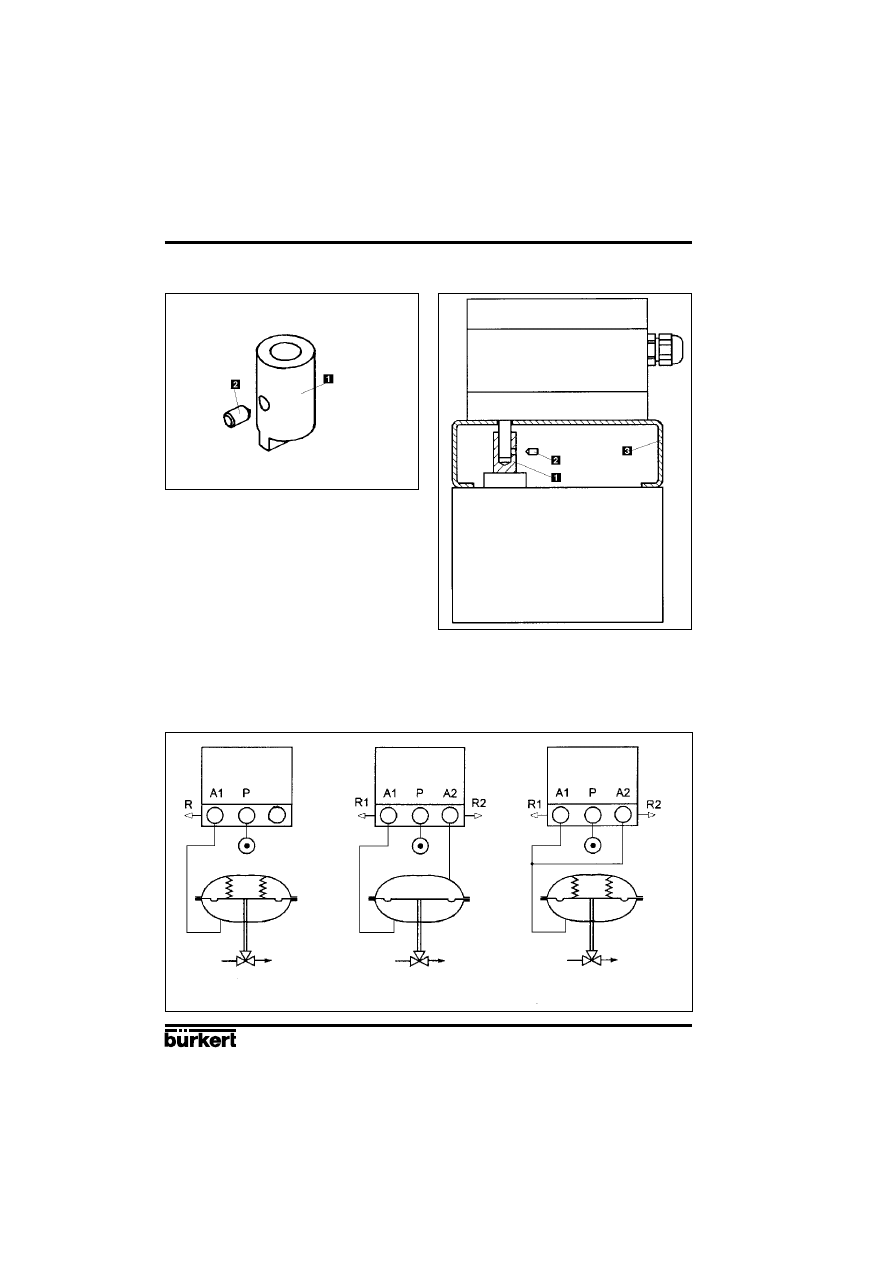
Continuous valve with rotary drive
Single acting
Double acting
Single acting, parallel
(for higher flow)
3.2 Fluid ports
Connect P port with compressed air supply (6 bar max.)
POSITIONER 1067
E-15-
Fluid Control Systems
3 INSTALLATION
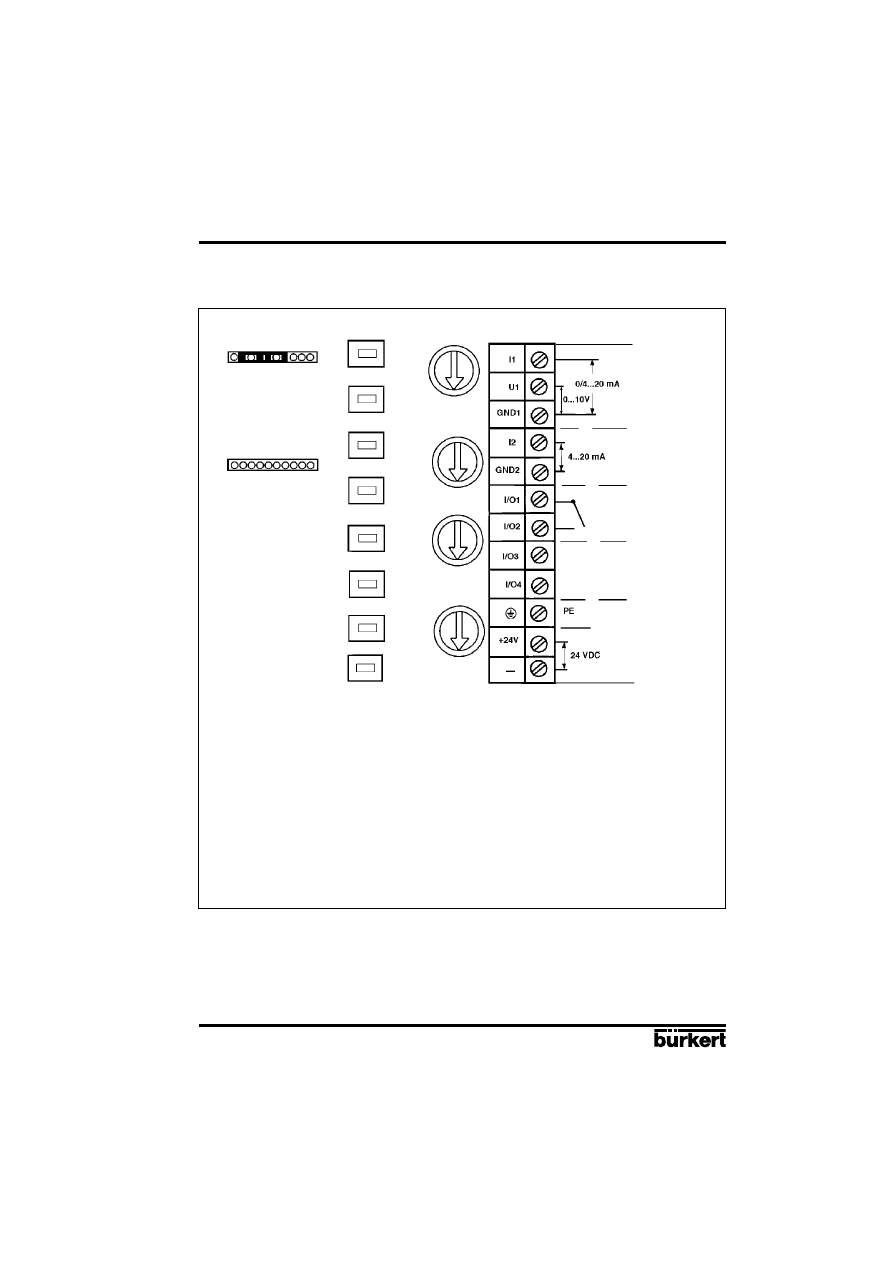
3.3 Electrical connections
Fig. 20
Assignment of terminals
Input U1 (unit signal 0 ... 10 V):
Input resistance
200 k
Ω
Input I1 (unit signal 0/4 ... 20mA):
Input resistance
< 175
Ω
Input I2 (unit signal 4 ... 20mA):
Input resistance
< 175
Ω
Caution: The PE terminal must be connected to a ground point using the shortest possible cable
(max. 30 cm) to ensure electromagnetic compatibility (EMC).
Signal input:
- either for valve
position control
- or for process
regulation control
Binary input
Contact
Output
(Option)
Power Supply
Input for process
regulation
E-16-
POSITIONER 1067
Fluid Control Systems
4 OPERATION
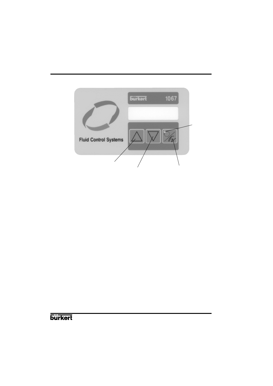
4.1 Controls and indicators
AUTOTUNE
„Arrow up“ key
„Arrow down“ key
MANUAL/AUTOMATIC key
LED
4.2 Operating levels
2 operating levels are provided for operation of the positioner:
1
°
Process operation level
This level, which is automatically set each time the unit is switched on, allows to change over between
the MANUAL and AUTOMATIC operating modes. In the MANUAL mode the valve can be opened
or closed by operating the „arrow keys“.
2
°
Configuration level
The purpose of the configuration level is to enable the basic functions to be specified on initial
commissioning and additional functions to be configured as required.
Each time the power is switched on, the positioner is in the
process operation
level in the AUTOMATIC
mode. A changeover to the MANUAL mode can be accomplished using the MANUAL/AUTOMATIC
key (cf § 4.4). From the
process operation
level it is possible to change over to the
configuration
level
by pressing the MANUAL/AUTOMATIC key and holding for 5 seconds.
POSITIONER 1067
E-17-
Fluid Control Systems
4 OPERATION
4.3 Setting up
The following basic settings are to be carried out on the initial setting up (commissioning) of the
positioner in conjunction with the 2632 angle-seat control valves (specification of basic functions):
- Specification of the positional feedback of the continuous valve to the positional transducer (direct
or lever),
- Specification of the unit signal input chosen for entering the set position (0 ... 20 mA, 4 ... 20 mA
or 0 ... 10 V),
- Initiating the automatic adaptation of the actuator to the valve being used.
When the power is switched on, the positioner is in the process control level. It is necessary to switch
to the configuration level for specification of the basic functions. To do this, press the MANUAL/
AUTOMATIC key and hold for 5 seconds. The first menu point X-SENS of the main menu is then
displayed.
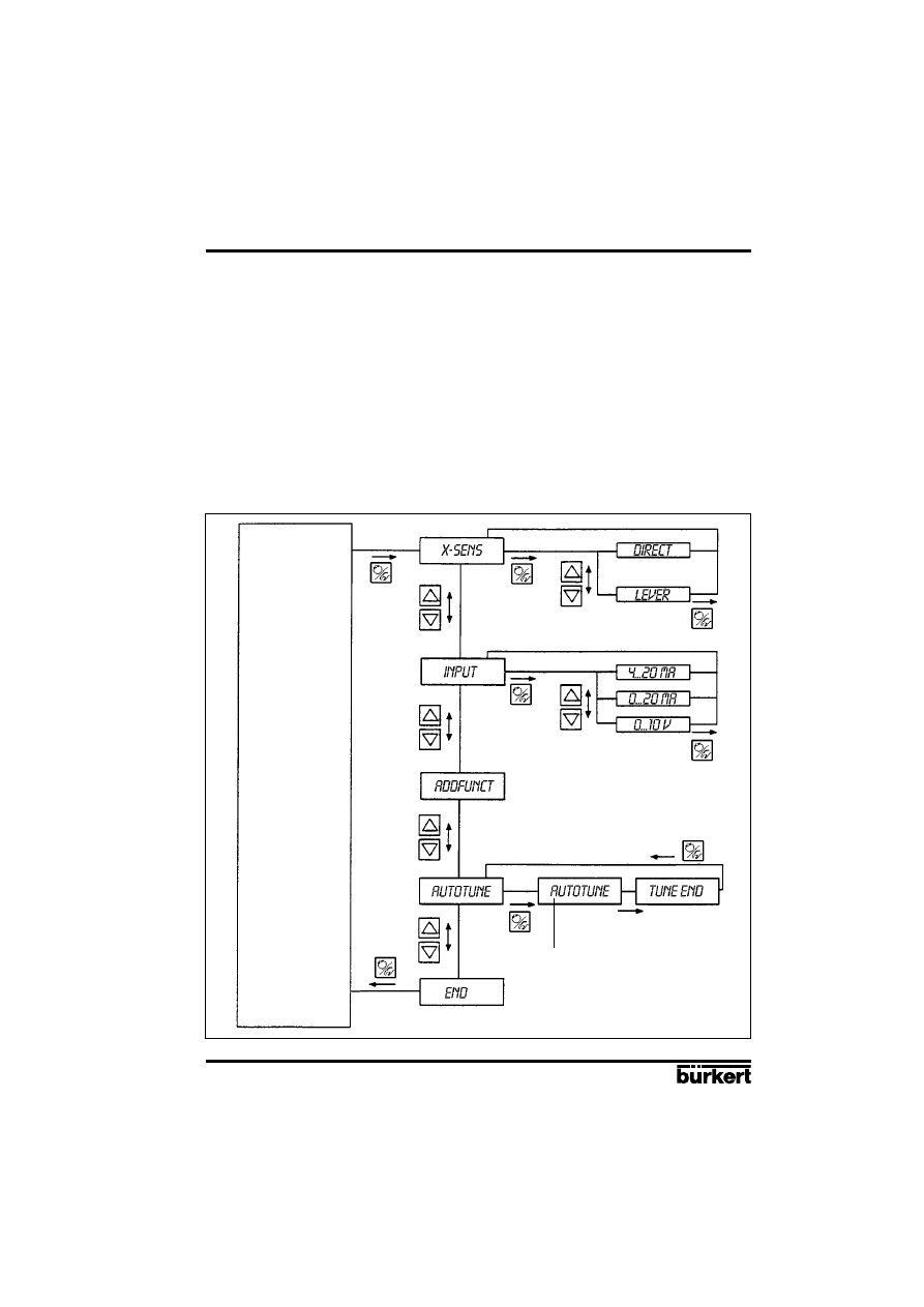
Fig. 21
Main menu for first setting up
Function
AUTOMATIC
or
MANUAL
after 30 to 120 sec.
BLINKING

E-18-
POSITIONER 1067
Fluid Control Systems
4 OPERATION
To perform a setting within the X-SENS and INPUT menu items, briefly press the MANUAL/
AUTOMATIC key again. One of the menu sub-items then appears in the display. It is possible to
switch back and forwards between these sub-items, each of which describes a possible setting, by
again pressing the arrow keys. The actual setting is carried out by pressing the MANUAL/ AUTOMATIC
key on the selected menu sub-item.
Fig. 22
Signification of the menu options in the main menu
Basic function
Associated settings
X-SENS
Type of information transfer between the actuator and travel measuring
system (factory-set to DIRECT)
- DIRECT
- Linear relationship
- LEVER
- Sinusoidal relationship (use of a lever)
INPUT
Specification of selected unit signals
- 4 ... 20 MA
- Unit signal current 4 ... 20 mA
- 0 ... 20 MA
- Unit signal current 0 ... 20 mA
- 0 ... 10 V
- Unit signal voltage 0 ... 10 V
ADDFUNCT
Configuration of additional functions
AUTOTUNE
Actuation of automatic adaptation of the actuator to the valve
END
End of menu
Under the menu option X-SENS, indicate whether the mechanical transmission of path information
from the positioner to the feedback/positional transducer is based on a linear or sinusoidal relationship.
A sinusoidal relationship results if the lever mechanism is used for the transmission of path information
(cf. section 3.1.1). In this event, when LEVER is confirmed an internal linearization takes place by
means of an approximated sinusoidal function.
The ADDFUNCT menu item can be skipped on the initial setting up. It is used only to configure
additional functions.
The AUTOTUNE menu item is used to start the programme for automatic parametering of the
positioner. This automatically triggers the following functions:
- Matching the sensor signal to the (physical) stroke of the control valve used.
- Determining parameters of PWM signals for control of the internal solenoid valves.
- Optimum adjustment of the control parameters of the position controller (target function: fastest
possible movement to the set position without hunting).
The programme for automatic parametering is started by setting the AUTOTUNE menu item in the
main menu and then pressing the MANUAL/AUTOMATIC key and holding for 5 seconds. TUNE is
displayed with a countdown from 5 to 0. The word AUTOTUNE then flashes for approximately 30 to
120 seconds (depending on the actuator volume). After the flashing ends, the message TUNE END
is displayed.
Note: In case of complete delivery of a valve fitted with a positioner, the AUTOTUNE function has
already been run through in factory. In order to obtain the best accuracy, it is recommended to run
the AUTOTUNE function once more before putting the valve in operation.
If it is not possible to fully complete the AUTOTUNE routine, an error message is displayed (refer to
the list of error messages in part 5).

POSITIONER 1067
E-19-
Fluid Control Systems
4 OPERATION
To leave the main menu for the settings during the setting up, first select the END menu item by
pressing the arrow keys. Then press the MANUAL/AUTOMATIC key to restore the unit to the operating
mode which was present before the changeover to the main menu (MANUAL or AUTOMATIC).
4.4 Process operation
4.4.1 Meaning of LEDs and keys in the
process operation
level
LED
Green LED in the MANUAL/AUTOMATIC key is on: AUTOMATIC mode
Green LED in the MANUAL/AUTOMATIC key is off: MANUAL mode
Keys
- Operation of the MANUAL/AUTOMATIC key (key pressed for less than 5 seconds) changes over
between the MANUAL and AUTOMATIC modes.
- Pressing the MANUAL/AUTOMATIC key and holding for longer than 5 seconds gives entry to the
configuration menu.
- Pressing the arrow keys in the AUTOMATIC mode with additional function PCONTRL SETPOINT
INTERN and display set to SP (holding for longer than 3 seconds): changes the setpoint value (see
section).
- Operation of the arrow keys in the AUTOMATIC mode (key held for less than 3 seconds) changes
over the display.
- Pressing the „Arrow up“ key in the MANUAL mode moves the actuator to open.
- Pressing the „Arrow down“ key in the MANUAL mode moves the actuator to closed.
4.4.2 Displays
Displays in the AUTOMATIC mode
Process controller inactive
The following displays are possible for the position controller.
Actual position of valve actuator:
XPOS___ (0...100%)
Set position of valve actuator:
WPOS___ (0...100%)
It is possible to change over between these displays by operating the „arrow keys“.
Process controller active
When the process controller is active, the following values can be displayed:
Actual value of process variable (actual process value):
PV____ (-99.9...999.9)
Desired value of process variable (desired process value):
SP____ (-99.9...999.9)
Actual value of valve drive:
XPOS____ (0...100%)
Desired value of valve drive:
WPOS____ (0...100%)
The arrow keys can be used to switch between these four displays. The «down arrow» key allows
paging through displayed values in the above sequence.
If the additional function PCONTROL SETPOINT INTERN (set desired value via keyboard) was
specified during configuration, pressing either of the two arrow keys for more than 3 seconds while
SP (Setpoint) is shown in the display activates the mode for changing the desired process value. If
the key is released after this time, the first digit of the desired process value flashes on and off. This
digit can be changed by pressing the key again. After confirmation with the HAND/AUTOMATIC key,
the set value is accepted. The same process can be applied to the other digits. When the fourth digit
has been confirmed, the mode switches back.
E-20-
POSITIONER 1067
Fluid Control Systems
4 OPERATION
Displays in the MANUAL mode
Process controller inactive
The actual position of the actuator is displayed:
XPOS___ (0...100%)
Process controller active
In the HAND operating condition no operations are being carried out, the actual value of the process
quantity is continuously displayed:
PV____ (-99.9...999.9).
If the arrow keys are pressed (cf. section) for manual actuation of the valve, the actual position is
displayed:
XPOS____ (0...100%)
When the keys are not being pressed, the display again shows the actual process value PV.
The changeover between the MANUAL and AUTOMATIC modes is achieved by operating the
MANUAL/AUTOMATIC key.
If the „Arrow up“ key is pressed whilst in the MANUAL mode, the continuous action valve is continuously
moved in the open direction by the actuator. When the key is released this operation is interrupted
and the valve remains in the position it has taken up. Pressing the „Arrow down“ moves the valve
towards the closed position in a corresponding manner.
If a different arrow key is additionally pressed after pressing an arrow key, the valve moves in rapid
action in the direction specified by the key which was first operated.
Changeover to the configuration level can be achieved in both the MANUAL and AUTOMATIC modes
by pressing the MANUAL/AUTOMATIC key and holding for 5 seconds. A switch back to the process
control level sets the mode which was present before the changeover.
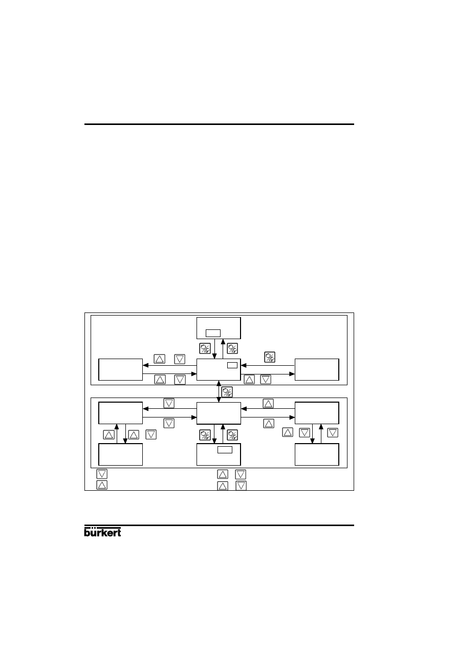
Fig. 23
Overview of the operation structure
END
SP
END
(>5s)
(>3s)
(>5s)
V
V
V
V
/
/
/
/
V
/
/
/
V
V
Press key
Release key
Press keys together
Release one of both
Configuration
Configuration
No operation
No operation
Display
paging
Process-
setpoint setting
Close actuator
normal speed
Open actuator
normal speed
Close actuator
high speed
Open actuator
high speed
Operation mode
AUTOMATIC
Operation mode
MANUAL

POSITIONER 1067
E-21-
Fluid Control Systems
4 OPERATION
4.5 Configuration
4.5.1 Additional functions
The operating concept of the positioner is based on a strict separation between basic and additional
functions. Only the basic functions are activated in the delivery state of the unit. These enable the
unit-specific basic settings to be carried out on the initial setting up (cf § 4.3). These are adequate
for normal operation. For more demanding tasks of position and process control, additional functions
which have been preset in the configuration level, can be selected and specified.
The additional functions are listed below. For further informations about these functions , see § 4.5.4.
Fig. 24
Additional functions
Additional
Parameter
Description
function
ACTUATE
Function of actuator
- SINGLE
INTERN
Single acting actuator with intern or without boost valves
BOOST
Single acting actuator with extern boost valves
- DOUBLE
- Double acting actuator
CHARACT
Selection of the transmission characteristic curve between the
input signal and stroke (correction characteristic curve)
- LINEAR
- Linear characteristic curve
- 1 : 25
- Equal percentage characteristic line with a rangeability of 1 : 25
- 1 : 50
- Equal percentage characteristic line with a rangeability of 1 : 50
- 25 : 1
- Inverse equal percentage characteristic with a
rangeability of 25 : 1
- 50 :1
-Inverse equal percentage characteristic with a
rangeability of 50 : 1
- FREE
- User-defined, characteristic line freely programmable
DEADBND
- DBD
Dead band with regard to the closed tight function system deviation
CLTIGHT
Close tight function
- CLT
- Closed tight threshold
DIRECTN
WPOS
Relationship between input signal and measure
- RISE
- Direct direction of action
- FALL
- Inverse direction of action
XPOS
Relationship between ventilation of the actuators chamber A1
and the setpoint
- RISE
- Direct direction of action
- FALL
- Inverse direction of action
SPLTRNG
Signal range splitting, input signal in % for the complete stroke
range through which the valve passes
- MIN
- Input of minimum value of input signal.
- MAX
- Input of maximum value of input signal.

E-22-
POSITIONER 1067
Fluid Control Systems
4 OPERATION
X-LIMIT
Limitation of mechanical range
- XMIN
- Input of initial value of stroke range in %.
- XMAX
- Input of final value of stroke range in %
X-TIME
Limitation of correcting time
- OPN FAST
- No limitation of correcting time during opening
- OPN SLOW
- Limitation of correcting time during opening
- CLS FAST
- No limitation of correcting time during closing
- CLS SLOW
- Limitation of correcting time during closing
PCONTRL
Process controller configuration
- SETPOINT
- Method of presetting desired value
INTERN
Desired value preset internally via keys
EXTERN
Desired value preset externally via signal input
- PARAM
- Process controller parameters
KP
Proportional correction value
TN
Reset time
TV
Rate time
X0
Operating point
DBD
No sensibility range of the process controller
- SCALE
- Scalling input and setpoint values
DP
Position of decimal point
PV-L
Lower scale value for process quantity
PV-H
Upper scale value for process quantity
SP-L
Lower scale value for setpoint (only for SETPOINT EXTERN)
SP-H
Upper scale value for setpoint (only for SETPOINT EXTERN)
BIN-IN
Operation of binary input.
- INACTIVE
- Binary input inactive
- SAFEPOS
- Safety position
SPOS
Position in %
- NORM OPN - Binary input open, if not active (closed)
- NORM CLS
- Binary input closed, if not active (open)
OUTPUT
Output configuration (option)
- ANALOG
- Analog or process position feedback
- BINARY
- Programmable Binary output
XDO
Control value deviation alarm
XD
Limit value of admissible control value deviation
NORM OPN Binary output normally open
NORM CLS Binary output normally closed
BOOST
- Signal output for external Booster valve
CODE
4 Positions user code
- MENU+M/A
Protection code for all operating functions
- MENU+M/A
Protection code for configuration menus
POSITIONER 1067
E-23-
Fluid Control Systems
4 OPERATION
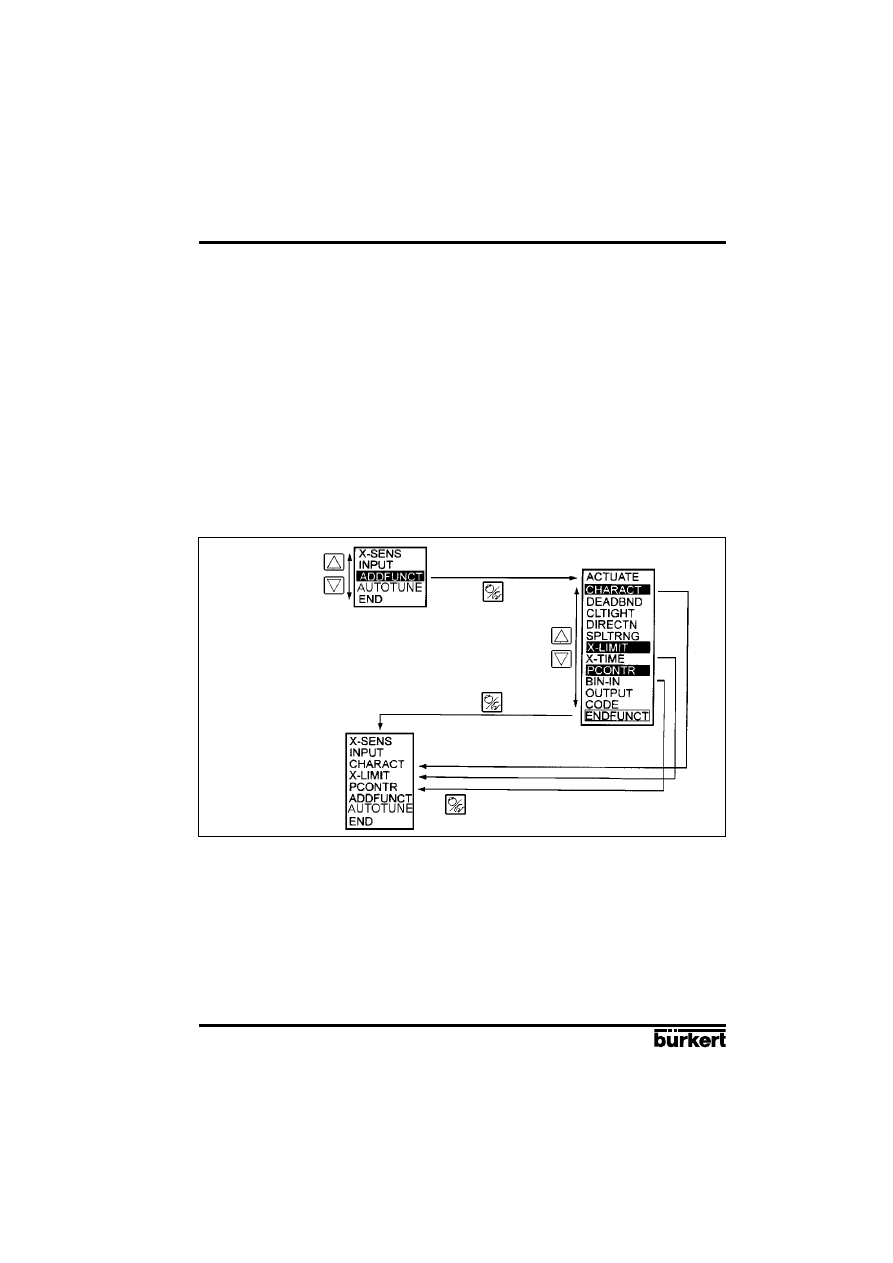
To remove additional functions which have brought into the main menu, again select the ADDFUNCT
function and then press the MANUAL/AUTOMATIC key in the additional menu. If only one additional
function marked with a star (
*
) is now selected and confirmed by pressing the MANUAL/AUTOMATIC
key, it will then be removed from the main menu, and desactivated..
Fig. 26 shows the complete configuration menu with all the basic and additional functions. Continued
selection in the vertical direction is achieved by pressing the appropriate arrow keys. Press the
MANUAL/AUTOMATIC key to move in the horizontal direction.
Setting numerical values in the appropriate menu items is achieved by pressing the „Arrow up“ key
once or several times (increment numerical value) or the „Arrow down“ (decrement numerical value).
In the case of 4-digit numbers, only the flashing position can be set using the „Arrow keys“. Pressing
the MANUAL/AUTOMATIC key changes to the next position.
4.5.2 Configuration menu
The configuration menu can be activated from the process control level by pressing the MANUAL/
AUTOMATIC key during 5 seconds. It consists of a main menu and additional menu. The main menu
contains mainly the basic functions which are to be specified on the initial setting up (cf § 4.3). The
additional menu covers all the additional functions which can be selected. It can be reached via the
ADDFUNCT item in the main menu. The equipment functions and parameters can only be specified
within the main menu. If necessary, however, the main menu can be extended by additional functions
from the additional menu, and these can in turn also be specified.
The principle of taking menu items from the additional menu into the main menu is described by figure
25. First select the ADDFUNCT item in the main menu and then press the MANUAL/ AUTOMATIC
key to enter the additional menu. When in the additional menu the „Arrow up“ or „Arrow down“ keys
can be pressed to set the required additional function. If this additional function is confirmed by
pressing the MANUAL/ AUTOMATIC key, it is then automatically marked with a star (*). All the
functions marked in this way are brought into the main menu after the ENDFUNCT is confirmed. The
additional functions can now be parametered in the main menu expanded in this way, and automatically
activated.
Fig. 25
Principle of integration of additional function in the main menu
Selection of item
ADDFUNCT
Additional menu
Expanded
main menu
Return to expanded
main menu
Confirmation of selected
additional functions for
importation in main menu
Main menu
Confirmation of
selected item
E-24-
POSITIONER 1067
Fluid Control Systems
4 OPERATION
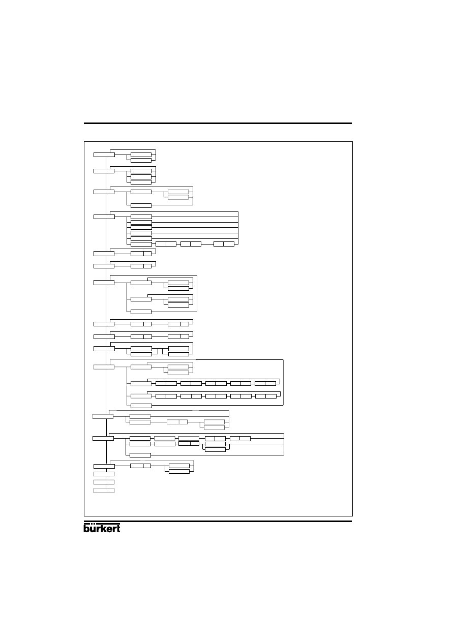
Fig. 26
Complete configuration menu
X-SENS
DIRECT
LEVER
INPUT
4...20MA
0...20MA
0...10V
ACTUATE
DOUBLE
CHARACT
LINEAR
1/25
1/50
25/1
50/1
FREE
0
5
100
DEADBND
DBD
CLTIGHT
CLT
DIRECTN
WPOS
XPOS
END
RISE
FALL
RISE
FALL
SPLTRNG
MIN
MAX
X-LIMIT
X-MIN
X-MAX
PCONTRL
SETPOINT
PARAM
SCALE
INTERN
EXTERN
KP
TN
TV
X0
X-TIME
OPN FAST
OPN SLOW
CLS FAST
CLS SLOW
SINGLE
INTERN
BOOST
END
DBD
PV-H
SP-L
SP-H
PV-L
DP
BIN-IN
INACTIVE
SAFEPOS
SPOS
NORM OPN
NORM CLS
ADDFUNCT
AUTOTUNE
END
A
OUTPUT
BINARY
CODE
ANALOG
NORM CLS
XD
XDO
NORM OPN
BOOST
CODE
MENU+M/A
MENU
WPOS
XPOS
PV
SP

POSITIONER 1067
E-25-
Fluid Control Systems
4 OPERATION
4.5.3 Function of keys in the configuration level
Operation of the „Arrow up“ key
- Scroll upwards in menu (selection).
- Incrementing numerical values in a selected and confirmed menu item.
Operation of the „Arrow down“ key
- Scrolling downwards in the menu (selection).
- Decrementing numerical values in a selected and confirmed menu item.
Operation of the MANUAL/AUTOMATIC key within the main menu
- Confirmation of a selected menu item.
- Confirmation of a set value.
Operation of the MANUAL/AUTOMATIC key within the additional menu
- Confirmation of a selected menu item of the additional menu for inclusion in the main menu. The
selected menu item is marked with a star (*) in the additional menu. The menu item now appears
in the main menu where it can be selected and manipulated.
- Confirmation of a selected menu item of the additional menu, marked with a star, for deletion from
the main menu.
4.5.4 Notes on the basic and additional functions
X-SENS (factory setting: DIRECT): Specification of the type of information transfer between the
continuous action valve (valve setting) and the travel measuring system.
Options:
DIRECT: There is a linear relationship between the valve position and the input signal of the
path-measuring system.
Examples:
Fitting the positioner to a piston valve (e.g. 2031) and using the external feedback/positional transducer
(linear potentiometer) to measure the piston position (see section 3.1.2 and Fig. 11). Here, the linear
movement of the piston is transformed into a linear movement of the potentiometer. A characteristic
correction is therefore not required.
Fitting the positioner to a flap valve with part-turn valve actuating drive (e.g. 3210) and using the
internal feedback/positional transducer (rotary potentiometer) to measure the flap position (see
section 3.1.3 and Fig. 15). The rotary movement of the flap is converted into a proportional rotary
movement of the potentiometer. A characteristic correction is not required.
LEVER: There is a sinusoidal relationship between the valve position and the input signal of
the path-measuring system.
Example:
Fitting the positioner to a membrane valve (e.g. 265) and using the internal feedback/positional
transducer (
rotary potentiometer
) to measure the valve position (see section 3.1.1 and
Fig. 7). Coupling is via a lever conforming to NAMUR. The linear movement of the membrane is
transformed into a rotary movement of the potentiometer. A sinusoidal curve results. In this option,
therefore, the transmission characteristic is linearized internally.
INPUT (factory setting: 4 - 20 mA): Specification of the selected unit signal.
Options:
4 - 20 mA: Use of the 4 ... 20 mA unit signal input
0 - 20 mA: Use of the 0 ... 20 mA unit signal input
0 - 10 V:
Use of the 0 ... 10 V unit signal input
E-26-
POSITIONER 1067
Fluid Control Systems
ACTUATE (factory setting: SINGLE, INTERN): Method of operation of the valve actuator used.
Options:
SINGLE, INTERN:
Use of a single acting actuator with intern or without boost valves,
SINGLE, BOOST:
Use of a single acting actuator with boost valves,
DOUBLE:
Use of a double acting actuator
4 OPERATION
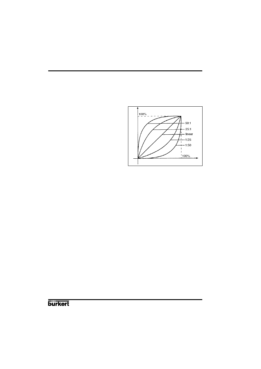
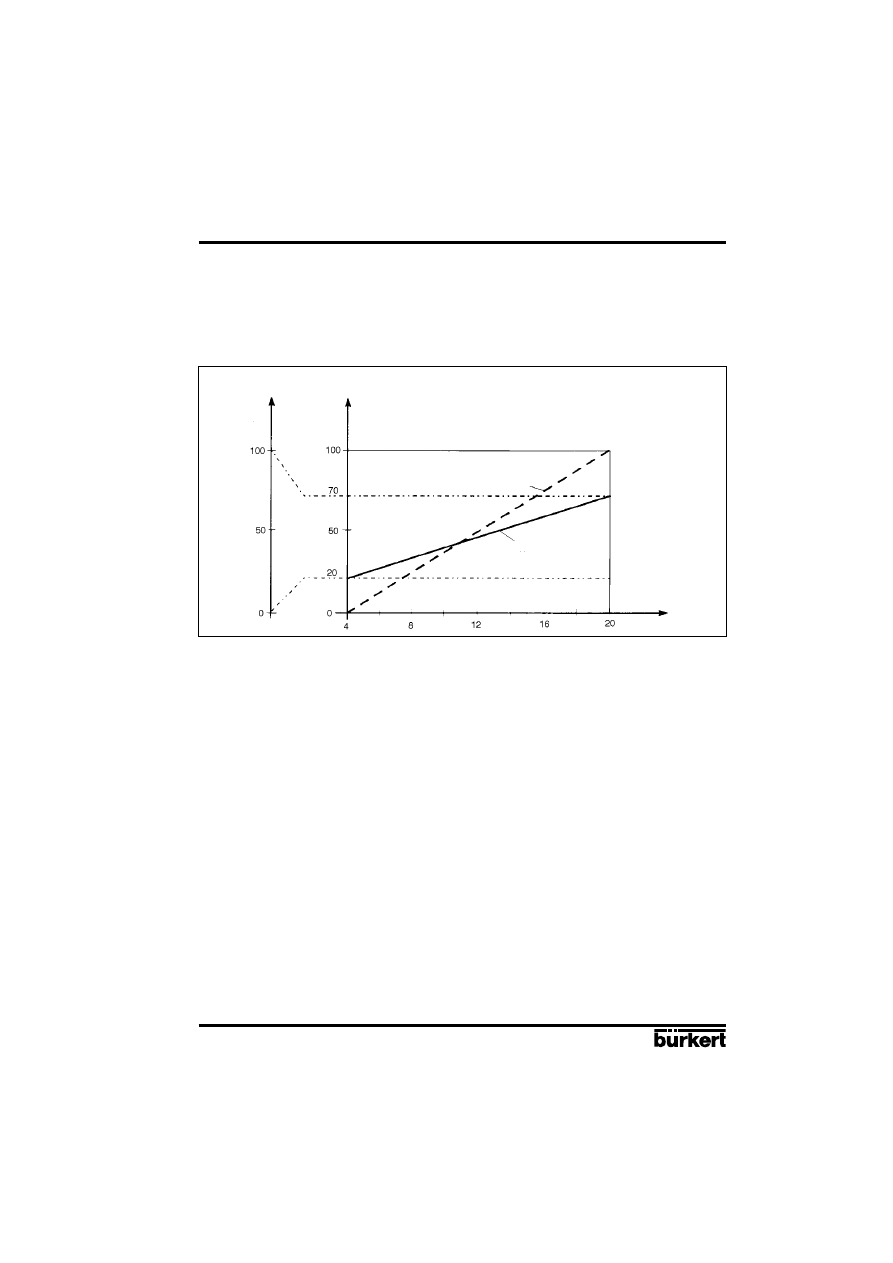
CHARACT (factory setting: LINEAR):
Customer-specific characteristic.
This additional function enables a transmission
characteristic curve with regard to the desired
value of the setting (set position) and valve stroke
for correction of the flow or operating curve to be
chosen (Fig 27).
Fig. 27
Corrective characteristic curves
Set position
P
lu
g
t
ra
v
e
l
The flow characteristic k
v
= f
(s)
characterises the flow of a valve and is expressed by the k
v
value
relative to the stroke s of the valve spindle. It is determined by the shape of the valve body. There
are normally two types of flow characteristic curves: linear and equal percentage. In the case of linear
characteristic curves equal changes in stroke ds are assigned to equal k
v
value changes dk
v
(dk
v
=
n
lin
ds). In the case an equal percentage characteristic curve a change in stroke ds corresponds to
an equal percentage change in the k
v
value (dk
v
/k
v
= n
gleichpr
ds).
The operating curve Q = f
(s)
represents the relationship between the rate of flow Q which flows through
a valve fitted in the system and the stroke s. This curve is also affected by the properties of the
pipelines, pumps and consumers. It therefore has a form which deviates from the flow characteristic
curve.
Specific requirements are usually laid down for the operating characteristic curve (e.g. linearity) in
the case of correcting tasks for closed loop control systems. Therefore it is sometimes necessary for
this reason to correct the pattern of the operating curve in a suitable manner. A transmission element
which implements various characteristic curves which can be used to correct the operating curve is
provided in the positioner for this purpose. One linear and various equal percentage characteristic
curves with a control ratio of 1:25, 1:50, 25:1 and 50:1 can be set (see fig. 27). It is also possible to
freely programme a characteristic curve via restart points.
Options:
LINEAR Linear characteristic curve
1:25
Equal percentage characteristic curve with a control ratio of 1:25
1:50
Equal percentage characteristic curve with a control ratio of 1:50
25:1
Inverse equal percentage characteristic curve with a control ratio of 25:1
50:1
Inverse equal percentage characteristic curve with a control ratio of 50:1
FREE
Freely-programmable characteristic curve based on temporary restart points

POSITIONER 1067
E-27-
Fluid Control Systems
4 OPERATION
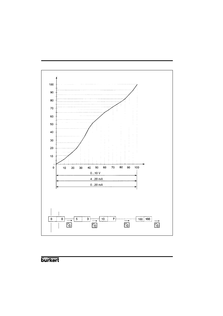
Input of the freely-programmable characteristic curve
The characteristic curve is defined by means of 21 restart points distributed uniformly over the set
positioning range of 0 ... 100%. These are spaced at 5%. A freely-selectable stroke (range 0 ... 100%)
can be assigned to each restart (Fig. 28). The difference between the values of the stroke of two
adjacent restart points shall not exceed 20%.
To input the characteristic curve points (function values), the FREE menu item is first set. After
operation of the MANUAL/ AUTOMATIC key the first restart point is input with the display 0 (%). After
this the next function value is 0 (%). A function value from 0 to 100% can be set using the arrow keys.
After confirmation using the MANUAL/AUTOMATIC key the next restart point is shown on the display
etc. If finally the MANUAL/AUTOMATIC key is pressed to confirm the function value for the last restart
point (100%), the program switches back to the CHARACT menu item.
Fig. 28 demonstrates an example of the free programming of a correction curve.
E-28-
POSITIONER 1067
Fluid Control Systems
4 OPERATION
Fig. 28
Example of a characteristic curve to be programmed
Plug travel (%)
Unit signal (%)
Set position (%)
Restart point
Input with "Arrow" keys
Plug travel (%)
POSITIONER 1067
E-29-
Fluid Control Systems
4 OPERATION
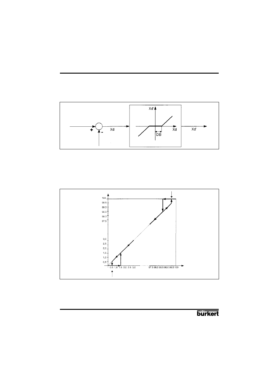
DEADBND (factory setting : DBD = 0.5%): Deadband around the system deviation
The DEADBND additional function enables the response of the actuator to occur only after a specific
system deviation [DBD] (Fig. 29). This „protects“ the servo valve.
Fig. 29
Deadband DBD
Control
difference
Set position
Actual position
To the controller
Rangeability:
Maximum 5% relative to the stroke range.
The bottom limit is determined by AUTOTUNE.
CLTIGHT (factory setting: CLT = 0.5%): Closed tight function.
The closed tight function ensures that the valve is tightly closed outside the control range.
Fig. 30
Closed tight function
programable from 0,0 to 10,0%
programable from 90,0 to 100%
Plug travel (%)
Set position (%)
CLT: Closed tight threshold
Specification of a value (%) from which the actuator air is completely exhausted (at 0%) or supplied
with air (at 100%). The opening or resumption of the control operation takes place with a hysteresis
of 1% (refer to Fig. 30).
Setting range:
0.0 ... 10.0% (applies both for complete exhausting as well as for complete air supply, see Fig. 30).
E-30-
POSITIONER 1067
Fluid Control Systems
4 OPERATION
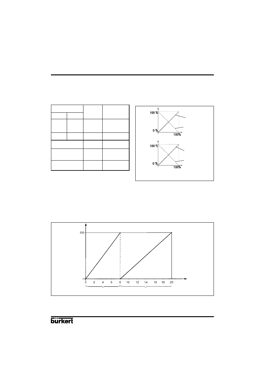
DIRECTN (FACTORY SETTING: WPOS = RISE, XPOS = RISE): Sense or direction of action.
By means of the
WPOS additional function the sense of action between the input signal and the
setpoint (WPOS). can be set, and also by means of
XPOS the assignment of the air supply state of
the actuator A1 to the indicated value (XPOS).
Setting range:
MIN:
0 ... 75 % of the unit signal range,
MAX: 25 ... 100 % of the unit signal range.
The minimum distance between MIN and MAX is 25%.
SPLTRNG (factory setting: MIN = 0%, MAX = 100%): Split range
This additional function enables the set value range of a positioner to be restricted by stipulating a
minimum and maximum value. This makes it possible to divide the used unit signal range (0 ... 10
V, 0 ... 20 mA or 4 ... 20 mA) over several positioners (without or with an overlap). In this way, several
valves can be partially used either simultaneously or in sequence as a final controlling element
(Fig. 32).
Fig. 32
Splitting a unit signal range into two set value ranges
Setpoint (mA)
Setpoint range
positioner 1
Setpoint range
positioner 2
Plug travel (%)
Input
DIRECTN
Setpoint
WPOS
I1
U1
(WPOS)
0/4 mA
0 V
RISE
0 %
20 mA
10 V
100 %
0/4 mA
0 V
FALL
100 %
20 mA
10 V
0 %
Air supply
DIRECTN
Measure
State A1
XPOS
(XPOS)
Air exhaust
RISE
0 %
Air on
100 %
Air exhaust
FALL
100 %
Air on
0 %
Fig. 31
Sense of action
0/4 mA Input signal
20 mA
0 V
10 V
air exhaust
air on
Air supply state
FALL
RISE
FALL
RISE
POSITIONER 1067
E-31-
Fluid Control Systems
4 OPERATION
X-LIMIT (factory setting: XMIN = 0%, XMAX = 100%): Stroke limitation.
This additional function enables the (physical) stroke to be limited to a given MIN and MAX percentage
value (Fig. 33). In the AUTOMATIC mode the stroke range of the limited stroke is then set to equal
100%. In the MANUAL mode, on the other hand, the physical stroke is displayed. (It should therefore
be noted that a limited stroke will be displayed differently in the AUTOMATIC and MANUAL modes).
Fig. 33
Stroke limitation
Limited plug
travel (%)
Limited plug
travel (%)
Physical plug
travel (%)
Unlimited plug
travel (%)
Setting range:
XMIN: 0 ... 50 % of the total stroke,
XMAX: 50 ... 100 % of the total stroke.
The minimum distance between XMIN and XMAX is 50%.
X-TIME (factory setting: OPN FAST, CLS FAST): Setting speed limitation
Options:
OPN FAST (open fast): Opening of the control valve happens with maximal control speed.
OPN SLOW (open slow): The maximum setting speed of the control valve is limited during
opening.
CLS FAST (close fast): Closing of the control valve happens with maximal control speed.
CLS SLOW (close slow): The maximum setting speed is limited when the control valve is
closing.
PCONTRL (process control): Process controller configuration
SETPOINT (factory setting: EXTERNAL): Preset desired value.
INTERN: Desired value can be input using the arrow keys (see § 4.4.2).
EXTERN: Desired value is preset via the standard signal input.
PARAM: Set parameters for process controller (PID controller)
KP: (Proportional correction value or amplification)
Range of settings:
0...99.99 (factory setting: 1.00)
TN: (reset time)
Range of settings:
0.5...999.9 (factory setting: 999.9)
Setpoint (mA)
E-32-
POSITIONER 1067
Fluid Control Systems
4 OPERATION
TV: (rate time)
Range of settings:
0.0...999.9 (factory setting: 0)
X0: (Operating point of process controller)
Range of settings:
0...100% (factory setting: 0%)
DBD: No sensibility range of the process controller
Range of settings:
0,2...5% (factory setting: 0,5 %)
SCALE: Scales the inputs of the process controller.
DP: Decimal point position
Range of settings:
0 ... 3 (factory setting 0)
PV-L: Lower scale value for actual process value. It is assigned to the smallest
current or voltage value of the standard signal.
Range of settings:
-99.9...990.0 (factory setting: 0.0)
PV-H: Upper scale value for actual process value. It is assigned to the greatest
current or voltage value of the standard signal.
Range of settings
: -90.0...999.9 (factory setting: 100.0)
SP-L: Lower scale value for desired process value (setpoint). It is assigned to the
smallest current or voltage value of the standard signal. (Applies only with the setting
SETPOINT EXTERN).
Range of settings
: -99.9...990.0 (factory setting: 0.0)
SP-H: Upper scale value for desired process value (setpoint). It is assigned to the
greatest current or voltage value of the standard signal. (Applies only with the setting
SETPOINT EXTERN).
Range of settings:
-90.0...999.9 (factory setting: 100.0)
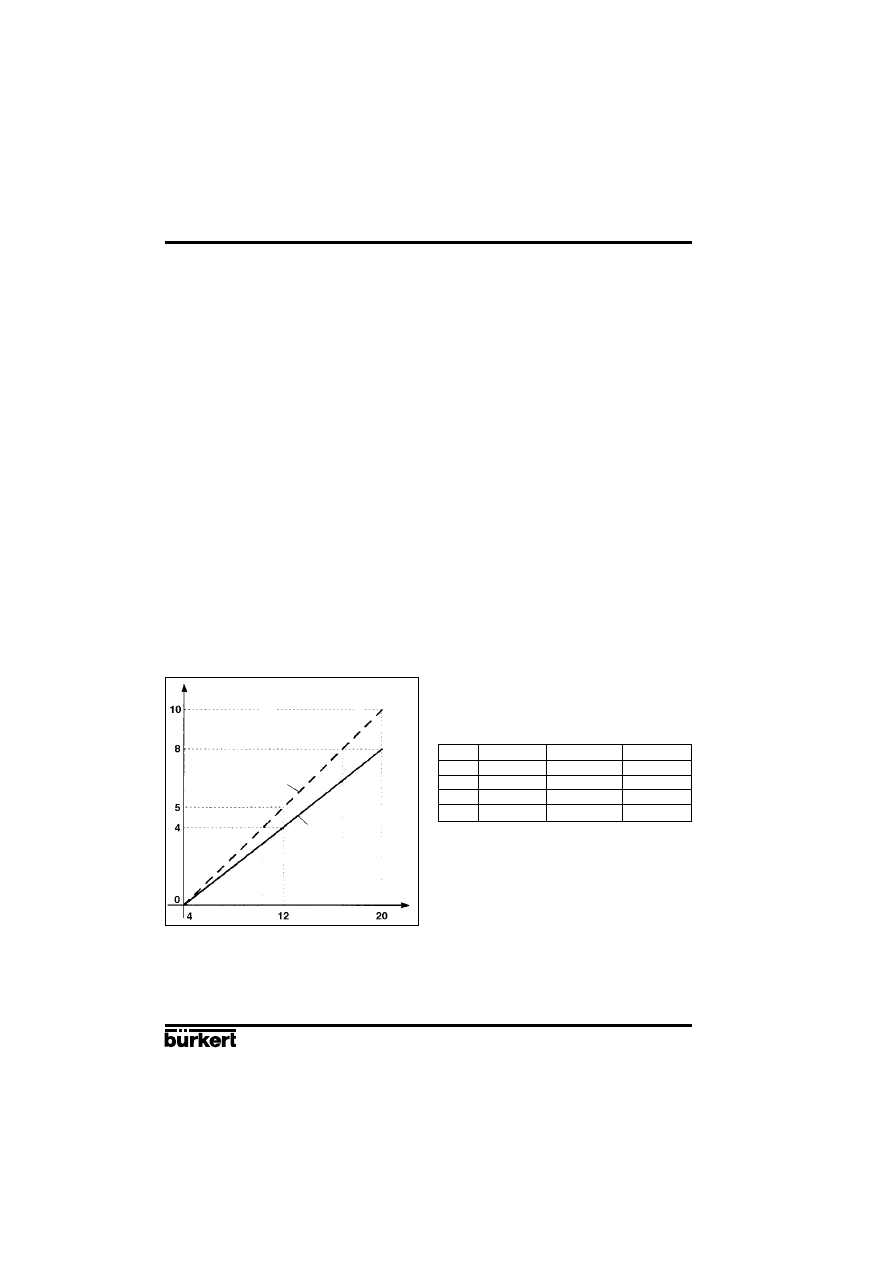
Example of scaling:
Actual process value via transmitter:
4...20 mA corresponds to 0...10 l/min
Desired process value from SPC:
4...20 mA corresponds to 0...8 l/min
Fig. 34
Example of scaling
Scaling value (l/min)
The input of large scale values increases display precision.
The amplification (KP) of the process controller relates to the set scale values.
With SETPOINT INTERN (desired values preset via the arrow keys) no scaling of the desired value
(SP-L, SP-H) is possible. It can be entered directly in correspondence with the scaled process
variable (PV-L, PV-H).
Standard signal (mA)
Actual
process value
Process
setpoint
Possible scale-value inputs in the example of
scaling
Variante 1
Variante 2
Variante 3
PV-L
0
0
0
PV-H
1,0
10,0
100,0
SP-L
0
0
0
SP-H
0,8
8,0
80,0

POSITIONER 1067
E-33-
Fluid Control Systems
4 OPERATION
BIN-IN (factory setting: INACTIVE): Binary input.
The action of the binary input (contact) can be specified by means of this additional function.
Options:
INACTIVE: Binary input is not active.
SAFEPOS (safety position): Input of a safety position SPOS selected if necessary.
Setting range:
0 ... 100% of the stroke range (factory setting: SPOS = 0).
NORM OPN (normalyl open): Binary input in de-energised position open (normally-open
contact or closer). Safety position is adopted when the contact closes.
NORM CLS (normally closed): Binary input in de-energised position closed (normally-closed
contact or opener). Safety position is adopted when the contact opens.
OUTPUT (option): (Additional function only activable with optional board.)
- ANALOG
Analog or process position feedback (4...20 mA) (see Appendix 3)
- BINARY
Programmable Binary output (see Appendix 4)
XDO
Alarm deviation value exceeds XD
XD
Deviation limit value ; Setting range: 0,1 ... 20% (Factory setting 1%)
NORM OPN Binary output normally open
NORM CLS Binary output normally closed
- ALARM
Alarm signal, XMIN or XMAX threshold reached
XMIN
Low alarm limit value ; Setting range: 0...100%
NORM OPN Binary output XMIN normally open
NORM CLS Binary output XMIN normally closed
XMAX
High alarm limit value ; Setting range: 0 ... 100%
NORM OPN Binary output XMAX normally open
NORM CLS Binary output XMAX normally closed
BOOST
Signal output for external Booster valve (see Appendix 4)
CODE (factory setting: 0000) User code. The positioner can be protected from unauthorised operation
by means of a 4-digit user code. 2 Levels of protection are available.
MENU+M/A:
All functions protected by the user-code
MENU:
Access to configuration menu restricted. MANU/AUTO switching and change
of process values are free (cf § 4.4.1).
Setting range:
0000 ... 9999
Regardless of the possibility of the existence of a preset code, there is a fixed programmed master
code which when entered enables all control operations to be performed.
ADDFUNCT (Additional functions): Additional functions.
This enables additional functions to be taken into the main menu and then removed (see § 4.5.2).
AUTOTUNE: Automatic parametering.
This function enables the program for automatic adaptation of the actuator to the valve in use to be
started. The following functions are automatically initiated (see section 4.3):
- The sensor signal is matched to the (physical) lift of the continuous valve,
- The parameters of the PWM signals are determined in order to control the internal magnetic valves,
- The parameters of the position controller are adjusted optimally.
This automatic setting of parameters is completed in approximately 30-120 seconds.
END: End of configuration menu.
(The software version is displayed on the right margin of the display). This menu item enables the
configuration menu to be left by operation of the MANUAL/AUTOMATIC key (cf § 4.3).
E-34-
POSITIONER 1067
Fluid Control Systems
4 OPERATION
Preconditions for manual operation using the rotary knobs.
- The power supply of the unit must not be connected under any circumstances.
- The pneumatic connections and the pressure supply must be present.
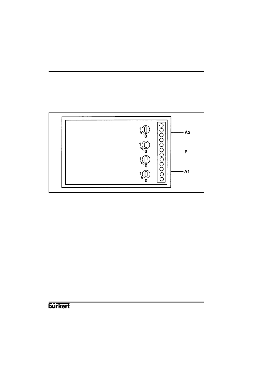
Settings
All rotary knobs are in position 0 (normal position):
Drive is vented.
In this case, in the design for double-acting actuating drives, the chamber connected to terminal A1
is vented and the chamber connected to terminal A2 is supplied with air.
All rotary knobs are in position 1:
Drive is supplied with air.
In this case, in the design for double-acting actuating drives, the chamber connected to terminal A1
is supplied with air and the chamber connected to terminal A2 is vented.
Caution!: All rotary knobs must be returned to the 0 position before connecting the power supply to
the positioner.
4.6 Manual operation without power supply
The solenoid valves integrated in the positioner can be manually operated without a power supply
by using rotary knobs. These rotary knobs (red) are accessible when the bonnet of the unit is opened.
They are located immediately behind the electrical terminals. Two rotary knobs are provided on the
type for single-acting actuator (Fig. 35).
Fig. 35
Manual operation
POSITIONER 1067
E-35-
Fluid Control Systems
4 OPERATION
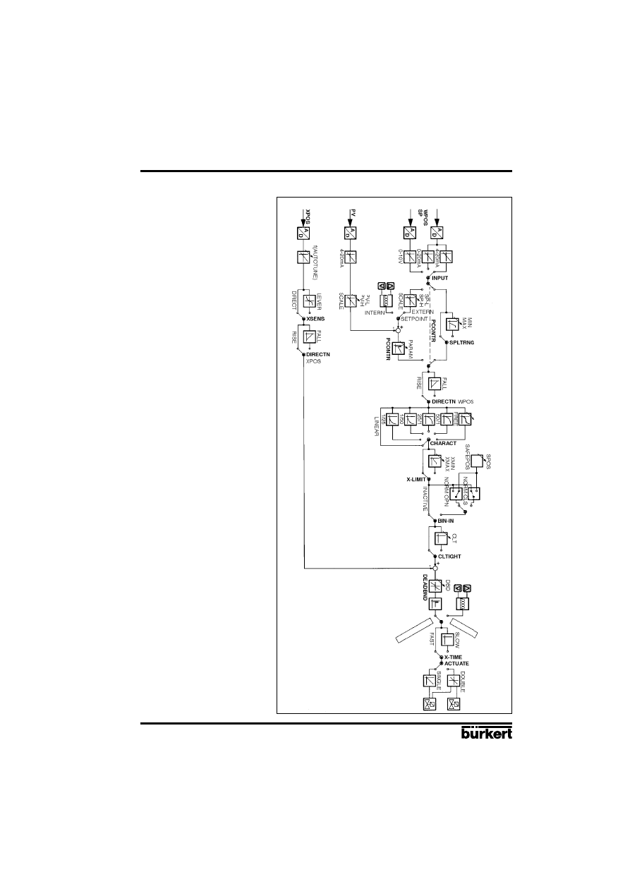
4.7 Structure of the positioner
Fig. 36
Flowchart of positioner
1067
Auto
ma
tic
Man
ual

E-36-
POSITIONER 1067
Fluid Control Systems
Fault messages
Faults during switch on
Message
Possible cause
Remedy
INT.ERROR
Internal fault
Not possible, unit defective
Fault messages during AUTOTUNE function
Message
Possible cause
Remedy
TURN POT
Range of the position transducer exceeded
Remove the positioner from
(only with internal feedback transducer option) the actuator,and turn
the transducer from 180
°. cf fig 2.
ERR 2
Actuator not adjustable
Fit the positioner with
Opening time < 0.5 s
bigger air chambers.
Reduce the air pressure
ERR 3
Miscellaneous failures causes
Manual operation of valve not
Check manual actuation
in basic setting
parameters
No air pressure connected
Check compressed air supply
Position transducer not connected
Check the electrical connection
of the transducer;If external position
control system only.(cf fig. 3)
Check the mechanical coupling
of the position controler;if internal
position control system (cf fig. 2)
5 MAINTENANCE
POSITIONER 1067
E-37-
Fluid Control Systems
Y
Xd
Y0
Ymax
Ymin
Xd
Y
APPENDIX
A1: Characteristics of PID controllers
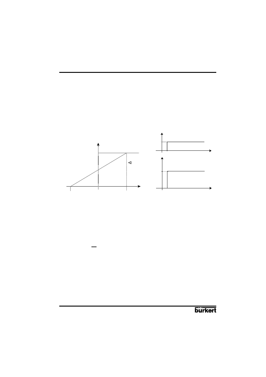
A PID controller has a proportional, an integral and a differential component (P, I and D components).
P component :
Function :
Y = Kp • Xd
Kp is the proportional action coefficient. It results from the ratio of the manipulating range
∆Y to the
proportional range
∆Xd.
t
t
X
Y
Xd
Kp.Xd
Kp. Xd
1
Ti
Characteristic
Step response
Characteristics :
Theoretically, a pure P controller operates without delay, i. e. it is fast and therefore dynamically
favorable. It has a lasting system deviation, i. e. it does not balance out the effects of disturbances
completely and is therefore relatively unfavorable from the static point of view.
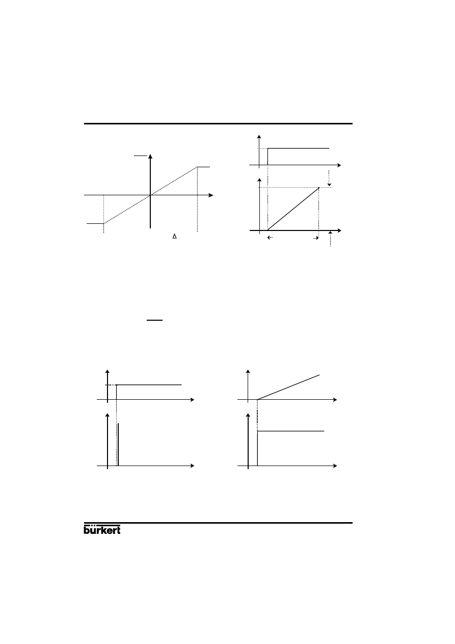
I component :
Function :
Y =
ƒ
Xd dt
Ti ist the integration or manipulating time. This is the time that elapses before the manipulated
variable has passed through the complete manipulating range.
M
a
n
ip
u
la
ti
n
g
ra
n
g
e
Proportional range
∆
Xd
E-38-
POSITIONER 1067
Fluid Control Systems
Characteristic
Step response
Characteristics :
A pure I controller eliminates the effects of occuring disturbances completely. Therefore, it has a
favorable static response. Owing to its finite manipulating speed, it operates more slowly than the P
controller and tends to oscillate. Therefore, it is relatively unfavorable from the dynamic point of view.
D component :
Function :
Y= Kd
Kd ist the derivative action coefficient.
The higher Kd is, the stronger the D influence is.
APPENDIX
Xd
Xd
dY
dt
t
t
X
Y
Xd
Ymax
Ymin
Ti
Step response
Rise response
Characteristics :
A controller with a D component reacts to changes in the controlled variable and is accordingly
capable of dissipating occurring deviations faster.
t
t
X
Y
Xd
t
t
X
Y
Control range
M
a
n
ip
u
la
ti
n
g
ra
n
g
e
∆
Y
Manipulating time
d Xd
dt
POSITIONER 1067
E-39-
Fluid Control Systems
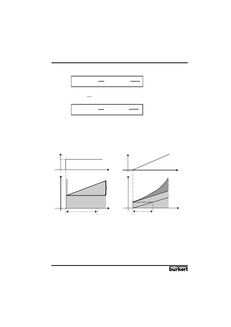
Supperposition of P-, I- and D components:
Y = Kp Xd + ƒ Xd dt + Kd
Where Kp•Ti = Tn and = Tv, results with regard to
functioning of the PID controller:
Y = Kp (Xd + ƒ Xd dt + Tv )
Kp :
Proportional action coefficient / gain
Tn :
Reset time
(the time needed to achieve the same manipulated variable change by the I
component as is produced as the result of the P component).
Tv :
Derivative action time
(the time to achieve a specific manipulated variable on the basis of
the D component earlier than when using a pure P controller).
APPENDIX
1
Ti
d Xd
dt
1
Tn
d Xd
dt
Kd
Kp
t
t
X
Y
}
}
}
Tv
Derivative action time
D component
I component
P component
t
t
X
Y
Xd
}
}
Tn
Reset time
D component
I component
P component
Step response of the PID controller
Rise response of the PID controller
E-40-
POSITIONER 1067
Fluid Control Systems
APPENDIX
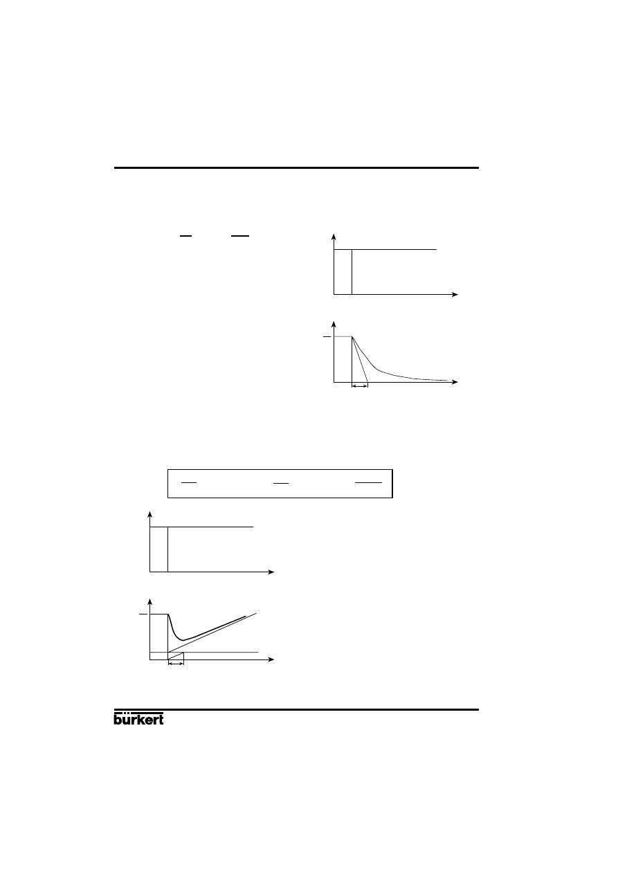
Realised PID controller
D component with delay :
In the 1067 positioner, the D component is realised with a delay T.
Function :
T + Y = Kd
Step response
Supperposition of P-, I- and DT components :
Function of the real PID controller :
T + Y = Kp (Xd + ƒ Xd dt + Tv )
dY
dt
1
Tn
d Xd
dt
Step response of the real PID controller
Kp Xd
X
Xd
Y
Kp
T
t
t
Tn
Tv
X
Xd
Y
Kd
T
t
t
T
dY
dt
dXd
dt
POSITIONER 1067
E-41-
Fluid Control Systems
t
X
APPENDIX
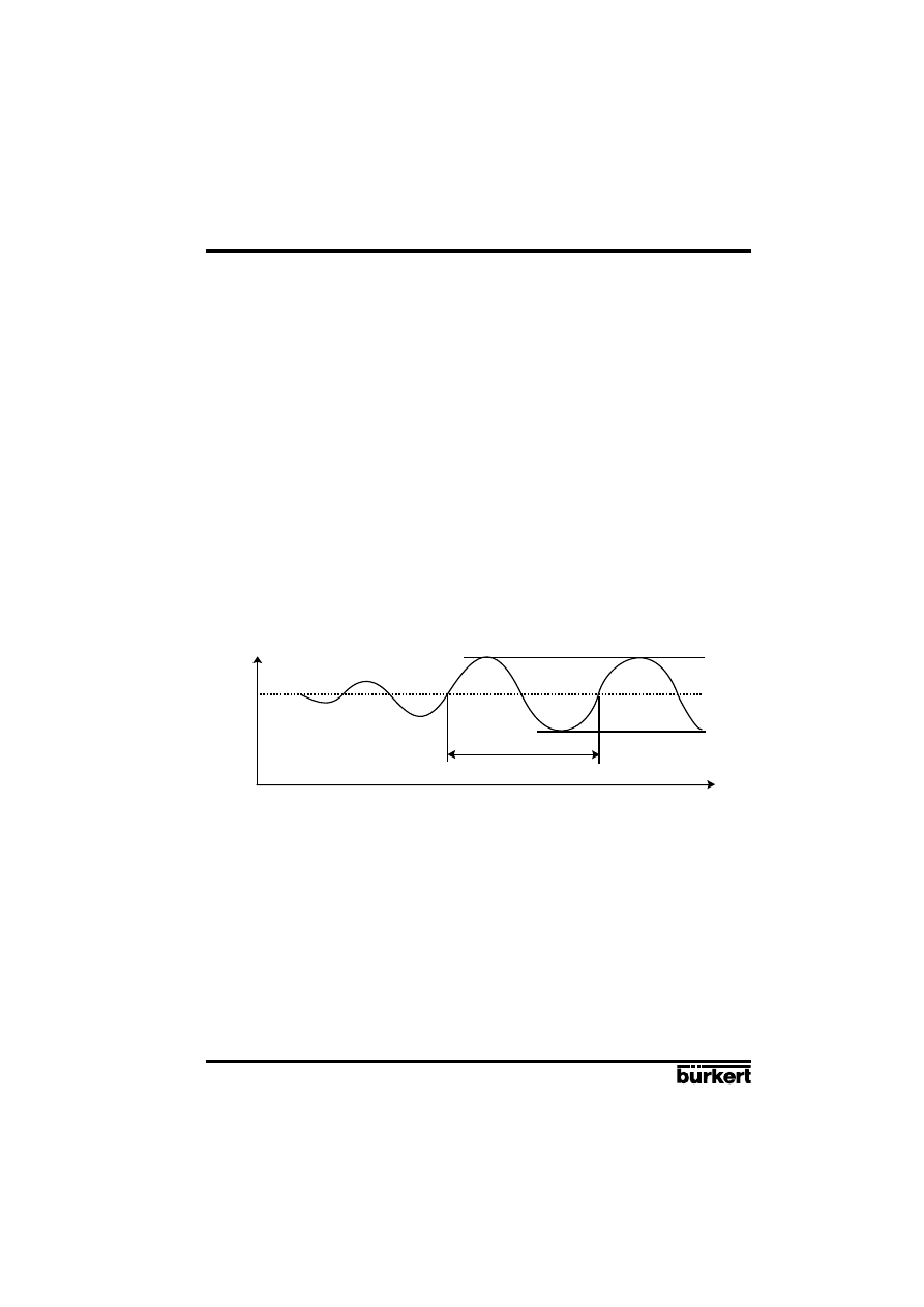
Figure :
Progression of the control variable at the stability limit
The proportional action coefficient set at the stability limit is referred as Kcrit. The resulting oscillation
period is referred to as Tcrit.
A2: Rules for adjusting PID controllers
The litterature on control systems specifies a series of adjustment rules with which a favorable
adjustment of controller parameters can be achieved experimentally. To avoid bad adjustments, the
conditions under which the respective adjustment rules have been elaborated must always be
observed. In addition to the characteristics of the controlled system and of the controller itself, it is
important to know whether it is intented to balance out a disturbance change or a command variable
change.
Adjustment rules according to Ziegler and Nichols (oscillation method)
When using this method, controller parameters are adjusted on the basis of the control loop's
response at the stability limit. In doing so, the controller parameters are adjusted so as to ensure that
the control loop begins to oscillate. A conclusion as to a favorable adjustment of the controller
parameters is reached from critical characteristic values occurring in this case. It goes without saying
that, when using this method, it must be possible to bring the control loop to oscillation.
Method:
- Set the controller as a P controller (i.e. Tn = 999, Tv = 0), initially selecting a low Kp value.
- Set the required setpoint.
- Increase Kp until the controlled variable oscillates continuously without attenuation (see following
figure).
Tcrit
Actual value
E-42-
POSITIONER 1067
Fluid Control Systems
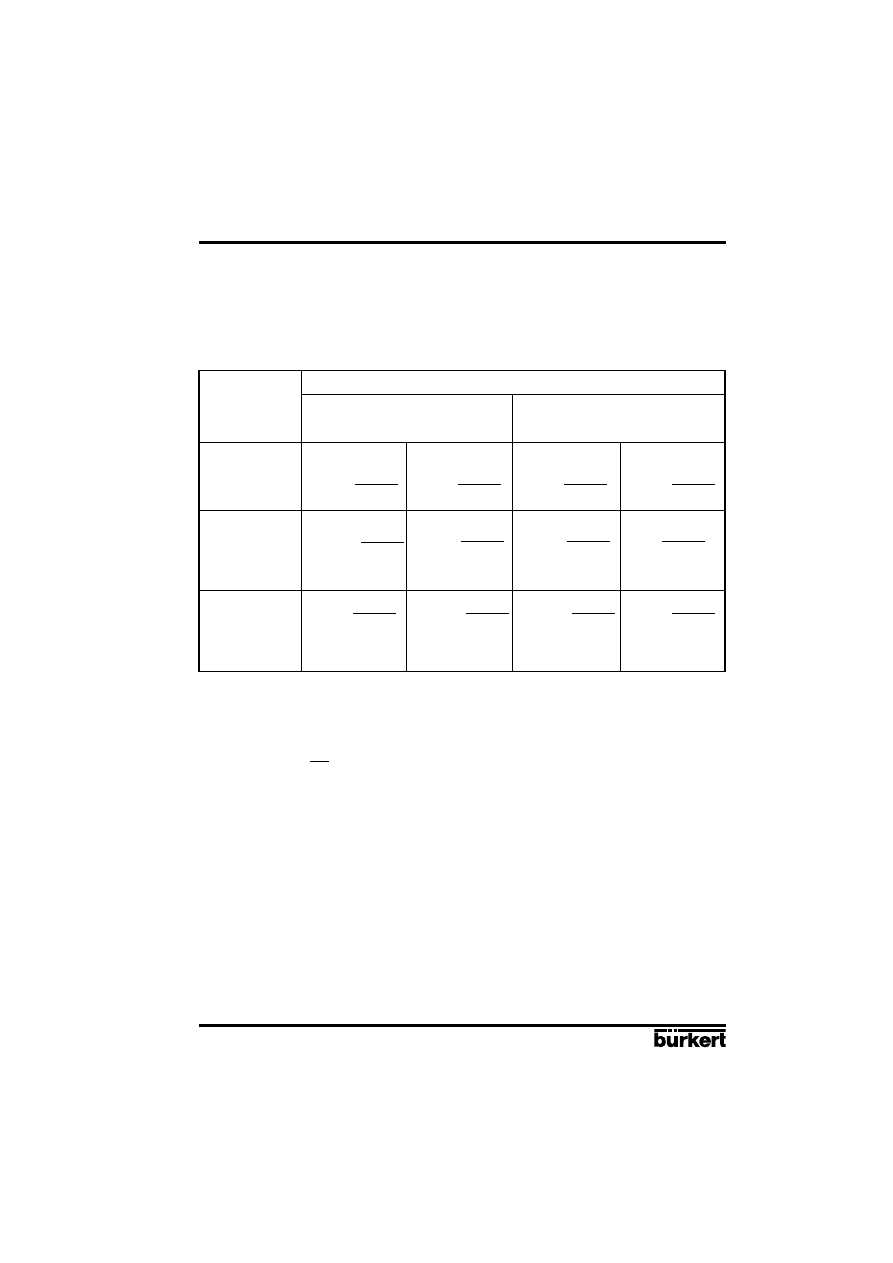
On the basis of Kcrit and Tcrit, the controller parameters can then be calculated in accordance with
the following table:
Parameter settings according to Ziegler und Nichols :
Controller type
Parameter settings
P controller
Kp = 0,5 Kcrit
P controller
Kp = 0,45 Kcrit
Tn = 0,85 Tcrit
P controller
Kp = 0,6 Kcrit
Tn = 0,5 Tcrit
Tv = 0,12 Tcrit
The Ziegler and Nichols adjustment rules were determined for P systems with a time delay of the first
order and a dead time. However, they apply only to controllers with a disturbance response, but not
to controllers with a command response.
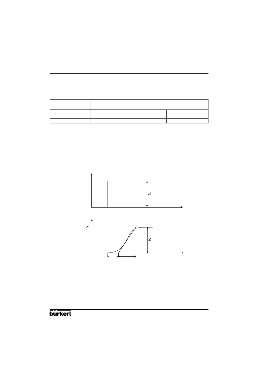
Adjustment rules according to Chien, Hrones and Reswick (manipulated variable methode):
When using this method, the controller parameters are adjusted on the basis of the controlled system
transition response. Be a 100% change in the manipulated variable; The times Tu and Tg are derived
from the progression of the variable (following figure). Ks is the proportional action coefficient of the
system.
APPENDIX
Figure :
Progression of the controlled variable after a manipulated variable change
∆
Y
Method :
- Set the controller to MANUAL mode.
- Output a manipulated variable change and record the controlled variable with a recorder.
- Switch off in good time if you encounter critical progressions (e. g. a risk of overheating) (Pay
attention to the fact that, in thermally inert systems, the actual value of the controlled variable may
increase further switching off).
Actual value
t
X
X
Tu
Tg
KS.
X
t
Y
Y
100%
POSITIONER 1067
E-43-
Fluid Control Systems
APPENDIX
As shown in the figure of the previous page, the proportional action coefficient Ks of the control
system can be calculated by way of the increase in the inflectional tangent, i. e. by way of
∆X/∆Y:
manipulated variable change)
Ks = ∆
X
∆Y
The following table lists the settings for the controller parameters depending on Tu, Tg and Ks for
command and disturbance response and for an aperiodic control operation as well as a control
operation with 20% overshoot. They apply to systems with a P response, with a dead time and with
a delay of the 1st order.
Parameter settings according to Chien, Hrones and Reswick :
Parameter settings
Controller
type
Aperiodic control operation
Control operation with
(0% overshoot)
20% overshoot
Command
Disturbance
Command
Disturbance
P controller
KP = 0,3
Kp = 0,3
Kp = 0,7
Kp = 0,7
PI controller
Kp = 0,35
Kp = 0,6
Kp = 0,6
Kp 0,7
Tn = 1,2 Tg
Tn = 4 • Tu
Tn = Tg
Tn = 2,3 • Tu
PID controller
Kp = 0,6
Kp = 0,95
Kp = 0,95
Kp = 1,2
Tn = Tg
Tn = 2,4 • Tu
Tn = 1,35 • Tg
Tn = 2 • Tu
Tv = 0,5 • Tu
Tv = 0,42 • Tu
Tv = 0,47 • Tu
Tv = 0,42 • Tu
Tg
Tu • Ks
Tg
Tu • Ks
Tg
Tu • Ks
Tg
Tu • Ks
Tg
Tu • Ks
Tg
Tu • Ks
Tg
Tu • Ks
Tg
Tu • Ks
Tg
Tu • Ks
Tg
Tu • Ks
Tg
Tu • Ks
Tg
Tu • Ks
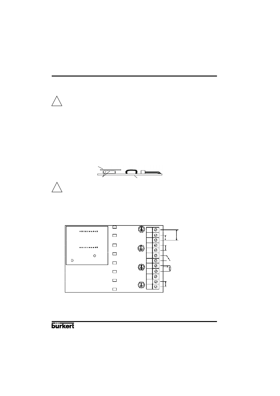
E-44-
POSITIONER 1067
Fluid Control Systems
APPENDIX
A3 : OPTION BOARD "4-20 mA ANALOG POSITION INDICATION"
(IDENT. 427193G): MOUNTING AND CONNECTION
The positioner must be equipped with the software version F, or higher. Check it in the
main menu, option END: it is displayed at the right-hand side of the screen.
Technical characteristics of the Option output of the positioner
-
Output signal for the current value : 4-20 mA
-
External working resistance / Input resistance of a connected device : 0-560 Ohms
-
Output error rate : < 0,05 %
-
Potential free output ; electrically separated from the position electronics.
Mounting
-
Disconnect the positioner from the voltage supply
-
Unscrew the 4 screws of the positioner cover and open the cover
-
Remove the 2 red jumpers from the motherboard
-
Insert the optional board onto the motherboard (see figure below)
Make sure the pins correctly slide into the motherboard.
-
Pass the cables through one of the 2 PG9 cable glands, dismantle them over 6 mm and
connect them to the connection block according to the connection schematic (terminals I/O3
and I/O4)
-
Close the cover and tighten the 4 screws, making sure neither the cables nor the wires are
wedged in.
Connection diagram
Configuration
-
Configurate the positioner as described in chapter 4.5.
-
Activate the analog position indication by choosing the ANALOG option of the OUTPUT
function
Analog Option board
Motherboard
pins
!
!
I1
U1
GND1
I2
GND2
I/O1
I/O2
I/O3
I/O4
PE
+24 V
-
0-10 V
0/4-20 mA
4-20 mA
I
L
= 4-20 mA
R
L
= 0-560 Ohm
24 V DC Supply Voltage
Analog Option board
Motherboard
+
-
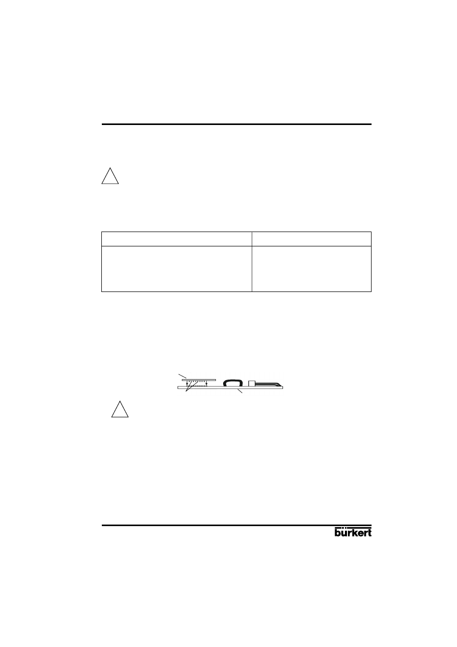
POSITIONER 1067
E-45-
Fluid Control Systems
APPENDIX
A4 : OPTION BOARD "BINARY POSITION INDICATION/BOOSTER"
(IDENT. 192801): MOUNTING AND CONNECTION
-
The positioner must be equipped with the software version F, or higher. Check it in the
main menu, option END: it is displayed at the right-hand side of the screen.
-
For positioners manufactured before 1996 mounting is only possible if the
motherboard is fitted with black connection blocks (if not, please contact you nearest
Bürkert agent).
Technical characteristics
Positioner
Relay
-
Operating voltage
: 24 VDC
-
Contact type : closed
-
Electric power consumption
: max. 30 W
-
Commutation current : 0,5 A
-
Electric connection
: screw terminals, -
Breaking capacity : 10 W
1,5 mm2 cross-
-
Contact resistance : 100 mOhm
section
Mounting
-
Disconnect the positioner from the voltage supply
-
Unscrew the 4 screws of the positioner cover and open the cover
-
Remove the 2 red jumpers from the motherboard
-
Insert the optional board onto the motherboard (see figure below)
Make sure the pins correctly slide into the motherboard.
-
Pass the cables through one of the 2 PG9 cable glands and dismantle them over 6 mm.
!
!
Option board
Motherboard
pins
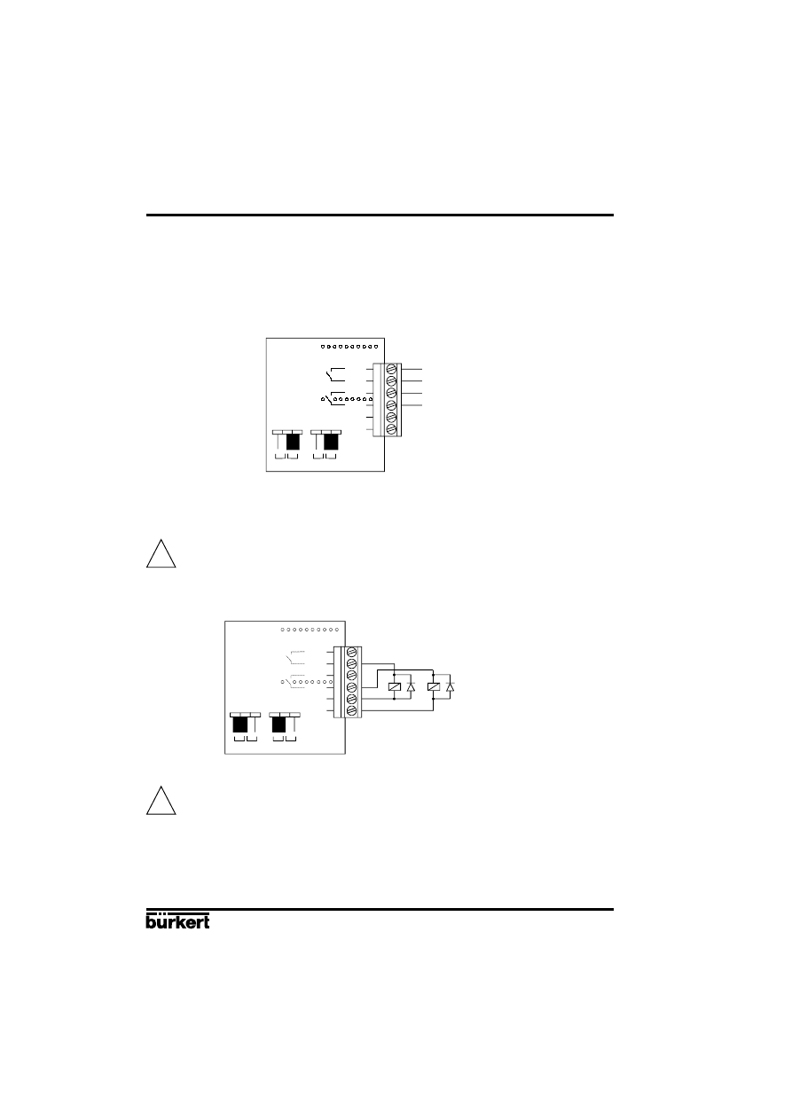
E-46-
POSITIONER 1067
Fluid Control Systems
APPENDIX
Connection
1) As potential free contacts
-
connect the cables to the O5 and O6 or O7 and O8 terminals according to the connection
schematic
-
place the jumper on the "REL" position (see figure below)
2) For connecting receivers to the outputs O6 and O8 (operating voltage of 24 V DC)
-
connect the cables to the terminals O6 and O8 and to GND3 and GND4 according to the connection
schematic below.
For inductive receivers, use the recovery diode.
-
place the jumper on the "U
out
" position (see figure below)
Short-circuit hazard : before closing the device, make sure the screws of the
connection block are tightened.
-
Close the cover and tighten the 4 screws, making sure the cables are not wedged in.
Configuration
-
Configurate the positioner as described in chapter 4.5.
-
Activate the binary position indication or the Booster function by choosing either the BINARY
or the BOOST option in the OUTPUT function.
!
!
O5
O6+
O7
O8+
GND3
GND4
U
out
Rel
U
out
Rel
O5
O6+
O7
O8+
GND3
GND4
U
out
Rel
U
out
Rel
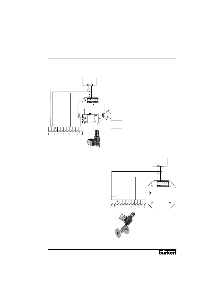
POSITIONER 1067
E-47-
Fluid Control Systems
APPENDIX
A5 : EXAMPLES OF EASY LINKS WITH THE POSITIONER 1067
4-20 mA
24 V=
-
+
-
+ 24 V
I/O4
I/O3
I/O2
I/O1 GND2 I2
I1
U1
GND1
24 VDC
PE
4-20 mA
0/4-20 mA
0-10 V
P+
-
+
P-
REL 1
300 mA
1067
2031
8045
6
5
4
3
2
1
PLC
8035
4-20 mA
24 V=
-
+
-
+ 24 V
I/O4
I/O3
I/O2
I/O1 GND2 I2
I1
U1
GND1
24 VDC
PE
4-20 mA
0/4-20 mA
0-10 V
6
5
4
3
2
1
1067
2632
EASY LINK between the positioner 1067
mounted on a diaphragm valve 2031 and
the flow transmitter 8045.
EASY LINK between the positioner
1067 mounted on a regulation valve
and the flow transmitter 8035.
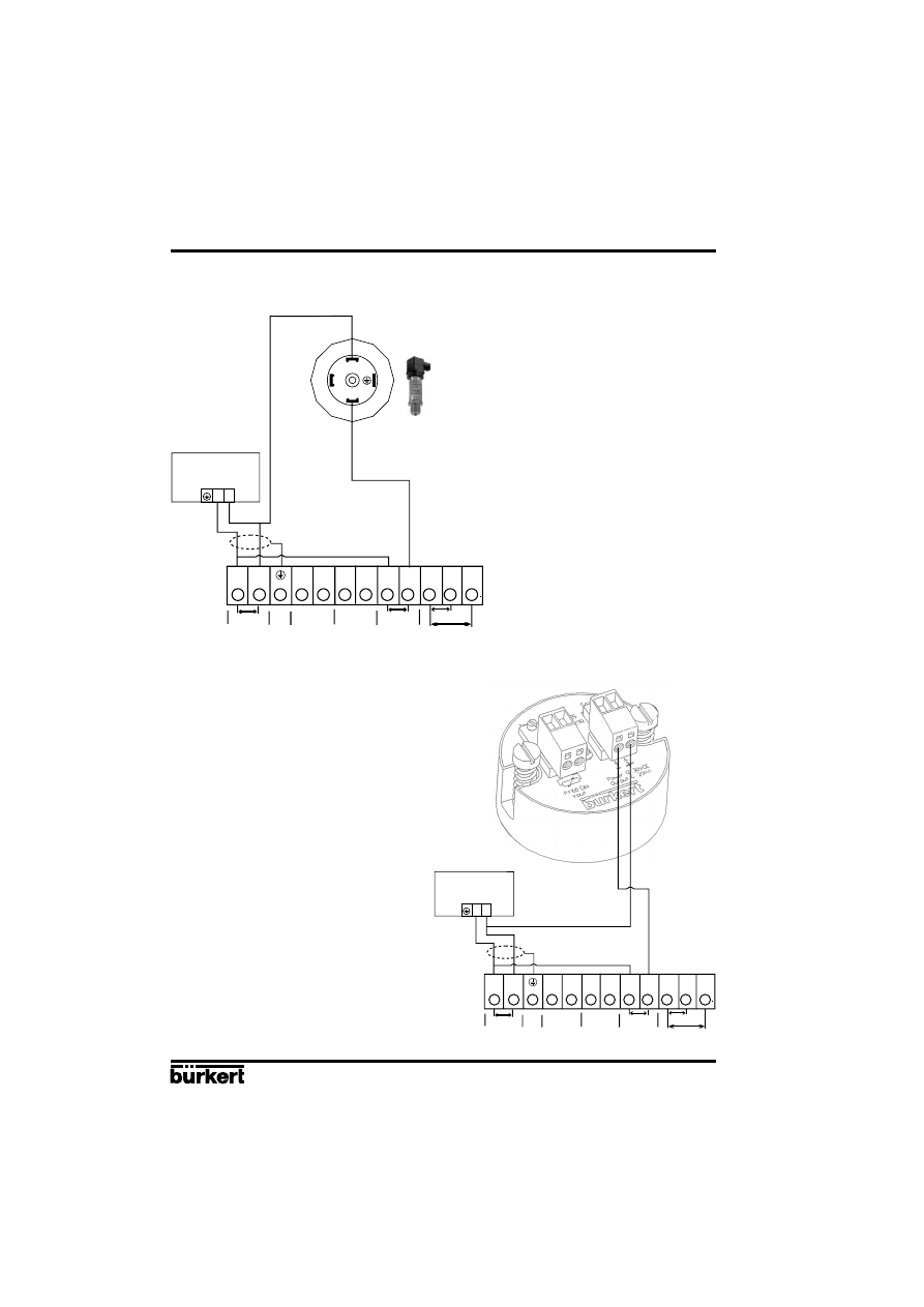
E-48-
POSITIONER 1067
Fluid Control Systems
APPENDIX
-
+ 24 V
I/O4
I/O3
I/O2
I/O1 GND2 I2
I1
U1
GND1
24 VDC
PE
4-20 mA
0/4-20 mA
0-10 V
24 V=
-
+
8323
1067
3
2
1
4-20 mA
L+
-
+ 24 V
I/O4
I/O3
I/O2
I/O1 GND2 I2
I1
U1
GND1
24 VDC
PE
4-20 mA
0/4-20 mA
0-10 V
24 V=
-
+
ST25
1067
EASY LINK between the positioner
1067 and the pressure sensor 8323.
EASY LINK between the positioner 1067
and the temperature transmitter ST25.

SERVICE
Bürkert Contromatic
China/HK Ltd.
Guangzhou Representative Office
Rm. 1305, Tower 2
Dong-Jun Plaza
Dongfeng, Road East
Guangzhou P.R.C
Tel +86 28 443 1895
Fax +86 28 445 1341
Denmark
Bürkert-Contromatic A/S
Hørkær 24
DK-2730 Herlev
Tel +45 44 50 75 00
Fax +45 44 50 75 75
Finland
Bürkert Oy
Atomitie 5
SF-00370 Helsinki
Tel +358 (0) 9 549 706 00
Fax +358 (0) 9 503 12 75
France
Bürkert Contromatic
B.P. 21
Triembach au Val
F-67220 Villé
Tel +33 (0) 388 58 91 11
Fax +33 (0) 388 57 09 61
Germany / Deutschland
Bürkert Steuer- und Regeltechnik
Christian-Bürkert-Straße 13-17
D-74653 Ingelfingen
Tel +49 7940 10-0
Fax +49 7940 10 361
Niederlassung NRW
Holzener Stra
βe 70
D-58708 Menden
Tel +49 2373 96 81-0
Fax +49 2373 96 81-52
Niederlassung Frankfurt
Am Flugplatz 27
D-63329 Egelsbach
Tel +49 6103 94 14-0
Fax +49 6103 94 14-66
Niederlassung München
Paul-Gerhardt-Allee 24
D-81245 München
Tel +49 89 82 92 28-0
Fax +49 89 82 92 28-50
Niederlassung Berlin
Bruno-Taut-Stra
βe 4
D-12524 Berlin
Tel +49 30 67 97 17-0
Fax +49 30 67 97 17-66
Niederlassung Dresden
Christian Bürkert Straße 2
D-01900 Großröhrsdorf
Tel +49 35952 3 63 00
Fax +49 35952 3 65 51
Niederlassung Hannover
Rendsburger Straße 12
D-30569 Hannover
Tel +49 511 9 02 76-0
Fax +49 511 9 02 76-66
Niederlassung Stuttgart
Karl-Benz-Straße 19
D-70794 Filderstadt (Bernh.)
Tel +49 711 4 51 10-0
Fax +49 711 4 51 10-66
Great Britain
Bürkert Contromatic Ltd.
Brimscombe Port Business Park
Brimscombe, Stroud, Glos.
GL5 2QF
Tel. +44 (0) 1453 73 13 53
Fax +44 (0) 1453 73 13 43
Hong Kong
Burkert Contromatic
(China/HK) Ltd.
Unit 708, Prosperity Centre
77-81 Container Port Road
Kwai Chung N.T.
Hong Kong
Tel +852 248 012 02
Fax +852 241 819 45
Italy
Bürkert Contromatic Italiana S.p.A.
Centro Direzionale 'Colombirolo'
Via Roma 74
I-20060 Cassina De' Pecchi (MI)
Tel +39 02 959 071
Fax +39 02 959 07 251
Japan
Bürkert Contromatic Ltd.
3-39-8 Shoan
Suginami-ku
Tokyo 167-0054
Tel +81 (0) 3 3247 3411
Fax +81 (0) 3 3247 3472
Korea
Bürkert Contromatic Korea Co. Ltd.
4-10 Yangjae-Dong
Seocho-Ku
Seoul 137-130
Tel. +82 (0) 2 346 255 92
Fax +82 (0) 2 346 255 94
Australia
Burkert Fluid Control Systems
Unit 1 No.2, Welder Road
Seven Hills NSW 2147
Tel +61 (0) 2 967 461 66
Fax +61 (0) 2 967 461 67
Austria
Bürkert Contromatic GmbH
Central and Eastern Europe
Diefenbachgasse 1-3
A-1150 Wien
Tel +43 (0) 1 894 13 33
Fax +43 (0) 1 894 13 00
Belgium
Bürkert Contromatic N.V/S.A
Middelmolenlaan 100
B-2100 Deurne
Tel +32 (0) 3 325 89 00,
Fax +32 (0) 3 325 61 61
Canada
Bürkert Contromatic Inc.
760 Pacific Road, Unit 3
Oakville, Ontario, L6L 6M5
Tel +1 905 847 55 66,
Fax +1 905 847 90 06
China
Bürkert Contromatic
(Suzhou) Co. Ltd.
9-2, Zhu Yuan Road
New District, Suzhou
Jiangsu, 215011 P.R.C
Tel +86 512 808 19 16
Fax +86 512 824 51 06
Bürkert Contromatic
China/HK Ltd.
Rm. 1313
No. 103, Cao Bao Road
200233 Shanghai P.R.C
Tel +86 21 6427 1946
Fax +86 21 6427 1945
Bürkert Contromatic
China/HK Ltd.
Beijing Office
Rm. 808, Jing Tai Building
No. 24, Jianguomen
Waidajie
100022 Beijing P.R.C
Tel +86 10 65 15 65 08
Fax +86 10 65 15 65 07
Bürkert Contromatic
China/HK Ltd.
Cheng Du Representative Office
Rm. 502, Fuji Building
No. 26 Shududadao
Dongfeng Street
Chengdu P.R.C
Tel +86 28 443 1895
Fax +86 28 445 1341

Spain
Bürkert Contromatic Española S.A.
Avda. Barcelona, 40
E-08970 Sant Joan Despi,
Barcelona
Tel +34 93 477 79 80
Fax +34 93 477 79 81
South Africa
Burkert Contromatic Pty.Ltd.
P.O.Box 26260, East Rand 1462
Republic of South Africa
Tel +27 (0) 11 397 2900
Fax +27 (0) 11 397 4428
Sweden
Bürkert Contromatic AB
Skeppsbron 13 B
S-21120 Malmö
Tel +46 (0) 40 664 51 00
Fax +46 (0) 40 664 51 01
Bürkert Contromatic AB
Havsörnstorget 21
Box 1002
S-12349 Farsta
Tel +46 (0) 40 664 51 00
Fax +46 (0) 8 724 60 22
Switzerland
Bürkert-Contromatic AG International
Bösch 71, P.O. Box
CH-6331 Hünenberg / ZG
Tel +41 (0) 41 785 66 66
Fax +41 (0) 41 785 66 33
Taiwan
Bürkert Contromatic Taiwan Ltd.
3F No. 475 Kuang-Fu South Road
R.O.C - Taipei City
Tel +886 (0) 2 275 831 99
Fax +886 (0) 2 275 824 99
Turkey
Bürkert Contromatik
Akiskan Kontrol Sistemleri Ticaret
A.S
1203/8 Sok. No. 2-E
Yenisehir
Izmir
Tel +90 (0) 232 459 53 95
Fax +90 (0) 232 459 76 94
SERVICE
Tzechia
Bürkert Contromatic Spol.s.r.o
Prosenice c. 180
CZ - 751 21 Prosenice
Tel +42 0641 226 180
Fax +42 0641 226 181
USA/West/Main office
Burkert Contromatic Corp.
2602 McGaw Avenue
Irvine, CA 92614, USA
Tel. +1 949 223 31 00
Fax +1 949 223 31 98
Malaysia
Bürkert Malaysia Sdn. Bhd.
N
° 22 Lorong Helang 2
11700, Sungai Dua
Penang
Tel. +60 (0) 4 657 64 49
Fax +60 (0) 4 657 21 06
Netherlands
Bürkert Contromatic BV
Computerweg 9
NL-3606 AV Maarssen
Tel. +31 (0) 346 58 10 10
Fax +31 (0) 346 56 37 17
New Zealand
Burkert Contromatic Ltd.
Unit 5, 23 Hannigan drive
Mt Welligton
Auckland
Tel +64 (0) 9 570 25 39
Fax +64 (0) 9 570 25 73
Norway
Bürkert Contromatic A/S
Hvamstubben 17
Box 243
N-2026 Skjetten
Tel +47 63 84 44 10
Fax +47 63 84 44 55
Philippines
Bürkert Contromatic Inc.
8467, West Service Rd Km 14
South Superhighway, Sunvalley
Paranaque City, Metro Manila
Tel +63 (0) 2 776 43 84
Fax +63 (0) 2 776 43 82
Poland
Bürkert Contromatic Sp.z.o.o.
Bernardynska street
PL-02-904
Warszawa
Tel +48 (0) 22 840 60 10
Fax +48 (0) 22 840 60 11
Singapore
Burkert Contromatic Singapore Pte.Ltd.
No.11 Playfair Road
Singapore 367986
Tel +65 383 26 12
Fax +65 383 26 11
Wyszukiwarka
Podobne podstrony:
1067
75 1067 1073 Elimination of Lubricants in Industries in Using Self Lubricating Wear Resistant
1067
(4363) konflikt w organizacjiid 1067 ppt
1067
1067
1067
1067
1067
1067
Bach, JS BWV 1067 Badinerie from Orchestral Suite no 2 (score)
Walter Burkert starozytne kulty misteryjne
DzU 00 98 1067 warunki techniczne baz i stacji paliw
Hart Jessica Romans Duo 1067 Ślub jak z bajki
(4363) konflikt w organizacjiid 1067 ppt
1067 Grady Robyn Bez pamięci
więcej podobnych podstron