2
The specifications in this publication are believed to be accurate and reliable. However, it is the responsibility of the
product user to determine the suitability of Thomson products for a specific application. While defective products will
be replaced without charge if promptly returned, no liability is assumed beyond such replacement.
For information or to place an order in North America: 1 (203) 271-6444 Europe: (44) 1276-691622 Asia: (65) 7474-888
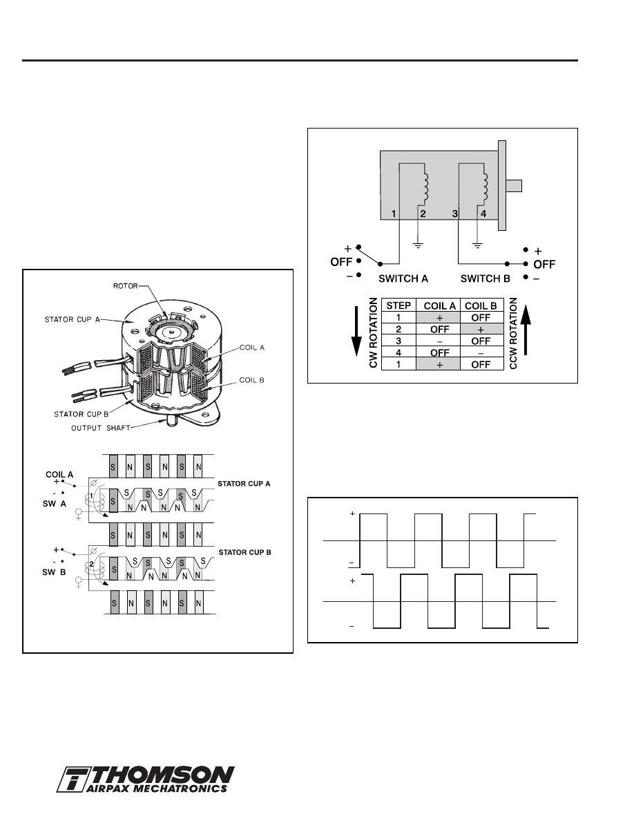
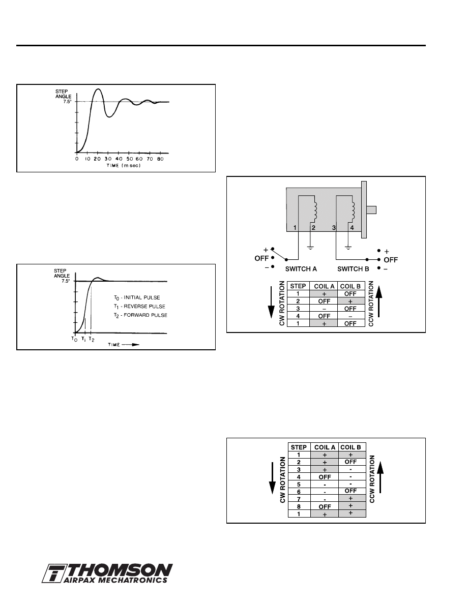
Figure 2: Schematic — 4-Step Switching Sequence.
Continuing the sequence causes the rotor to rotate forward.
Reversing the sequence reverses the direction of rotation. Thus, the
stepper motor can be easily controlled by a pulse input drive which
can be a 2-flip-flop logic circuit operated either open or closed loop.
Operated at a fixed frequency, the electrical input to the motor is a
2-phase 90° shifted square wave as shown below in Fig. 3.
Figure 1: Cutaway 2
∅
— Permanent Magnet Stepper Motor.
Interaction between the rotor and stator (opposite poles attracting and
likes repelling) causes the rotor to move 1/4 of a pole pitch per winding
polarity change. A 2-phase motor with 12 pole pairs per stator-coil
section would thus move 48 steps per revolution or 7.5° per step.
Stepper Motor Technology
The stepper motor is a device used to convert electrical pulses into
discrete mechanical rotational movements.
The Thomson Airpax Mechatronics stepper motors described in this
guide are 2-phase permanent magnet (PM) motors which provide
discrete angular movement every time the polarity of a winding is
changed.
CONSTRUCTION
In a typical motor, electrical power is applied to two coils. Two stator
cups formed around each of these coils, with pole pairs
mechanically displaced by 1/2 a pole pitch, become alternately
energized North and South magnetic poles. Between the two
stator-coil pairs, the displacement is 1/4 of a pole pitch.
The permanent magnet rotor is magnetized with the same number
of pole pairs as contained by the stator-coil section.
ELECTRICAL INPUT
The normal electrical input is a 4-step switching sequence as is
shown in Figure 2.
Figure 3: Voltage Wave Form — Fixed Frequency —
4-Step Sequence.
Since each step of the rotor can be controlled by a pulse input to a
drive circuit, the stepper motor used with modern digital circuits,
microprocessors and transistors provides accurate speed and
position control along with long life and reliability.
LAYOUT DIAGRAM OF STEP PER MOTOR SHOWING A
GIVEN STATOR POLARITY AND ROTOR POSITION.
COIL A
COIL B
3
The specifications in this publication are believed to be accurate and reliable. However, it is the responsibility of the
product user to determine the suitability of Thomson products for a specific application. While defective products will
be replaced without charge if promptly returned, no liability is assumed beyond such replacement.
For information or to place an order in North America: 1 (203) 271-6444 Europe: (44) 1276-691622 Asia: (65) 7474-888
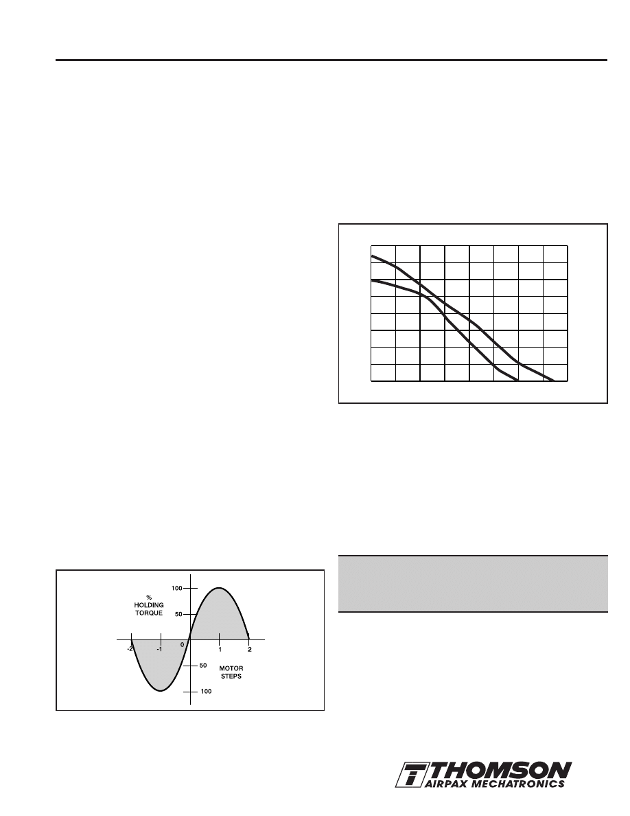
Figure 4: Torque Deflection.
RESIDUAL TORQUE
The non-energized detent torque of a permanent magnet stepper
motor is called
residual torque. A result of the permanent magnet flux
and bearing friction, it has a value of approximately 1/10 the holding
torque. This characteristic of PM steppers is useful in holding a load in
the proper position even when the motor is de-energized. The position,
however, will not be held as accurately as when the motor is energized.
DYNAMIC TORQUE
A typical torque versus step rate (speed) characteristic curve is
shown in Figure 5.
Figure 5: Torque/Speed — (Thomson Airpax 57L048B L/R
Stepper).
The PULL IN curve shows what torque load the motor can start and
stop without loss of a step when started and stopped at a constant
step or pulse rate.
The PULL OUT curve is the torque available when the motor is
slowly accelerated to the operating rate. It is thus the actual dynamic
torque produced by the motor.
The difference between the PULL IN and PULL OUT torque curves
is the torque lost due to accelerating the motor rotor inertia.
The torque/speed characteristic curves are key
to selecting the right motor and control drive method
for a specific application.
Note: In order to properly analyze application requirements, the load
torque must be defined as being either Frictional and/or Inertial.
(See Handy Formula Section in this engineering guide on pages 12
and 13 for resolving the load torque values. Also, an additional
“Application Notes” section is located on pages 10 and 11.)
0
10
20
30
40
50
60
70
80
0
1.42
2.83
4.25
5.67
7.08
8.50
9.92
11.3
TORQUE VS SPEED
57L048B L/R PHASE DRIVE
PULL OUT
PULL IN
T
ORQ
UE (mN
•m
)
SPEED (PPS)
OZ-IN
0
100
200
300
400
STEP ANGLE
Step angles for steppers are available in a range from .72° to 90°.
Standard step angles for Thomson Airpax steppers are:
3.6º
— 100 steps per rev.
7.5°
— 48 steps per rev.
15°
— 24 steps per rev.
18°
— 20 steps per rev.
A movement of any multiple of these angles is possible. For example,
six steps of a 15° stepper motor would give a movement of 90°.
ACCURACY
A 7.5° stepper motor, either under a load or no load condition, will
have a step-to-step accuracy of 6.6% or 0.5º. This error is non-
cumulative so that even after making a full revolution, the position of
the rotor shaft will be 360º ± 0.5º.
The step error is noncumulative. It averages out to zero within a
4-step sequence which corresponds to 360 electrical degrees. A
particular step characteristic of the 4-step is to sequence repeatedly
using the same coil, magnetic polarity and flux path. Thus, the most
accurate movement would be to step in multiples of four, since
electrical and magnetic imbalances are eliminated. Increased accuracy
also results from movements which are multiples of two steps.
Keeping this in mind, positioning applications should use 2 or 4 steps
(or multiples thereof) for each desired measured increment, wherever
possible.
TORQUE
The torque produced by a specific stepper motor depends on
several factors:
1/ The Step Rate
2/ The Drive Current Supplied to the Windings
3/ The Drive Design
HOLDING TORQUE
At standstill (zero steps/sec and rated current), the torque required
to deflect the rotor a full step is called the holding torque. Normally,
the holding torque is higher than the running torque and, thus, acts
as a strong brake in holding a load. Since deflection varies with
load, the higher the holding torque the more accurate the position
will be held. Note in the curve below in Fig. 4, that a 2-step
deflection corresponding to a phase displacement of 180, results in
zero torque. A 1-step plus or minus displacement represents the
initial lag that occurs when the motor is given a step command.
4
The specifications in this publication are believed to be accurate and reliable. However, it is the responsibility of the
product user to determine the suitability of Thomson products for a specific application. While defective products will
be replaced without charge if promptly returned, no liability is assumed beyond such replacement.
For information or to place an order in North America: 1 (203) 271-6444 Europe: (44) 1276-691622 Asia: (65) 7474-888
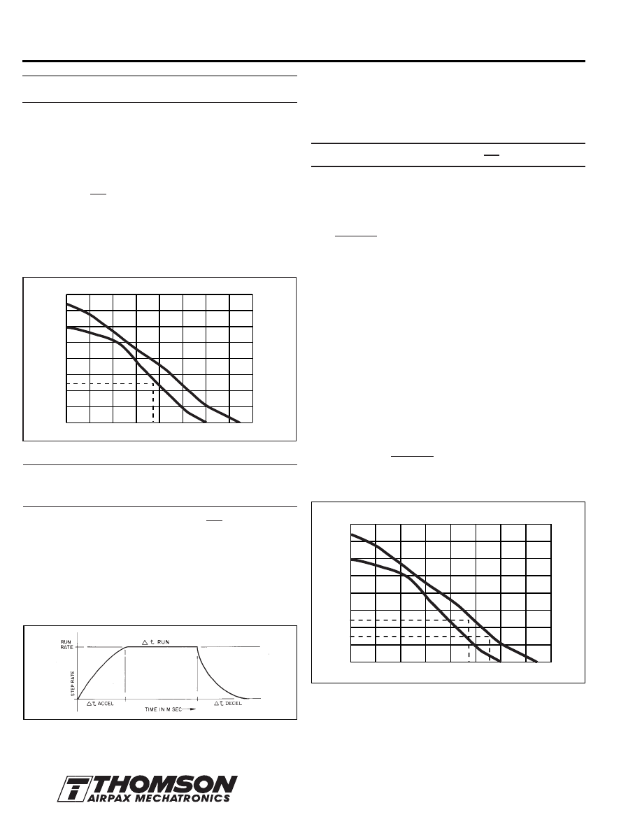
Use the
PULL IN curve if the control circuit provides no
acceleration and the load is frictional only.
Example: Frictional Torque Load.
Using a torque wrench, a frictional load is measured to be 25 mN•m
(3.54 oz-in). It is desired to move this load 67.5° in .06 sec or less.
Solution:
1. If a 7.5° motor is used, then the motor would have to take nine
steps to move 67.5°.
A rate of v =
= 150 steps/sec or higher is thus required.
2. Referring to Fig. 6, the maximum PULL IN error rate with a torque
of 25 mN•m is 185 steps/sec. (It is assumed no acceleration
control is provided.)
3. Therefore, a 57L048B motor could be used at 150 steps per
second — allowing a safety factor.
Figure 6: Torque/Speed — Frictional Load.
Use the PULL OUT curve, in conjunction with a Torque =
Inertia x Acceleration equation (T= J
α
), when the load is
inertial and/or acceleration control is provided.
In this equation, acceleration or ramping
α
= is in radians/sec
2
.
RAMPING
Acceleration control or ramping is normally accomplished by gating
on a voltage controlled oscillator (VCO) and associated charging
capacitor. Varying the RC time constant will give different ramping
times. A typical VCO acceleration control frequency plot for an
incremental movement with equal acceleration and deceleration
time would be as shown in Fig. 7.
0
10
20
30
40
50
60
70
80
0
1.42
2.83
4.25
5.67
7.08
8.50
9.92
11.3
TORQUE VS SPEED
57L048B L/R 2-PHASE DRIVE
PULL OUT
PULL IN
T
ORQ
UE (mN
•m)
SPEED (PPS)
OZ-IN
0
100
200
300
400
Figure 7: Step Rate/Time.
Acceleration also may be accomplished by changing the timing of
the input pulses (frequency). For example, the frequency could start
at a 1/4 rate, go to a 1/2 rate, 3/4 rate and finally the running rate.
A. Applications where:
Ramping acceleration or deceleration control time is allowed.
T
J
(Torque mN•m) = J
T
x x K
Where J
T
= Rotor Interia (g•m
2
) plus Load Inertia (g•m
2
)
∆
v = Step rate change
∆
t = Time allowed for acceleration in seconds
K = (converts steps/sec to radians/sec)
K = .13
for 7.5° — 48 steps/revolution
K = .26
for 15° — 24 steps/revolution
K = .314 for 18° — 20 steps/revolution
In order to solve an application problem using acceleration ramping,
it is usually necessary to make several estimates according to a
procedure similar to the one used to solve the following example:
Example: Frictional Torque Plus Inertial Load with Acceleration Control.
An assembly device must move 4 mm in less than 0.5 sec. The
motor will drive a lead screw through a gear ratio. The lead screw
and gear ratio were selected so that 100 steps of a 7.5° motor =
4 mm. The total Inertial Load (rotor + gear + screw) =
25 x 10
-4
g•m
2
. The Frictional Load = 15 mN•m
Solution:
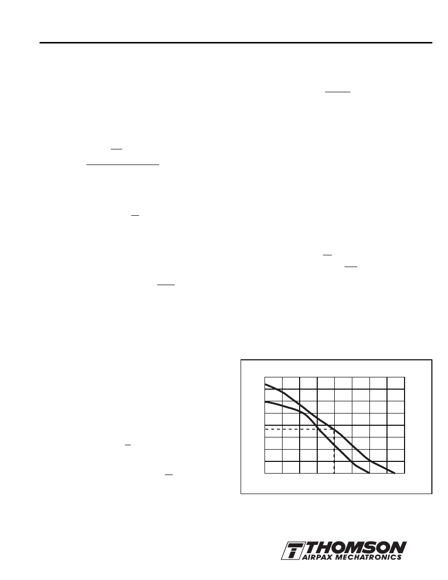
1. Select a stepper motor PULL OUT curve which allows a torque in
excess of 15 mN•m at a step rate greater than
v = = 200 steps /sec
Referring to Fig. 8, determine the maximum possible rate (vF) with
the frictional load only.
Figure 8: Torque/Speed — Friction Plus Inertia.
(Thomson Airpax 57L048B L/R Stepper).
9
.06
∆
v
∆
t
2
π
steps/rev
100 steps
0.5 sec
∆
v
∆
t
0
10
20
30
40
50
60
70
80
0
1.42
2.83
4.25
5.67
7.08
8.50
9.92
11.3
TORQUE VS SPEED
57L048B L/R 2-PHASE DRIVE
PULL OUT
PULL IN
T
ORQ
UE (mN
•m
)
SPEED (PPS)
OZ-IN
0
100
200
300
400
5
The specifications in this publication are believed to be accurate and reliable. However, it is the responsibility of the
product user to determine the suitability of Thomson products for a specific application. While defective products will
be replaced without charge if promptly returned, no liability is assumed beyond such replacement.
For information or to place an order in North America: 1 (203) 271-6444 Europe: (44) 1276-691622 Asia: (65) 7474-888
Where:
JT = Rotor Inertia (g•m
2
) plus Load Inertia (g•m
2
)
v = steps/sec rate
K =
(“K” values as shown in application A on page 4)
Example: Friction Plus Inertia – No Acceleration Ramping.
A tape capstan is to be driven by a stepper motor. The frictional
drag torque (TF) is 15.3 mN•m and the inertia of the capstan is
10 x 10
-4
g•m
2
. The capstan must rotate in 7.5° increments at a
rate of 200 steps per second.
Solution:
Since a torque greater than 15.3 mN•m at 200 steps per second is
needed, consider a 57L048B motor.
The Total Inertia = Motor Rotor Inertia + Load Inertia.
JT = JR + JL
= (34 x 10
-4
+ 10 x 10
-4
) g•m
2
= 44 x 10
-4
g•m
2
1. Since there is no acceleration ramping, use the equation:
TJ = JT x x K (K = .13)
TJ = 44 x 10
-4
x x .13
TJ = 11.4 mN•m
2. Total Torque
= TF + TJ
= 15.3 + 11.4
= 26.7 mN•m
3. Refer to the PULL OUT curve Fig. 9, at speed of 200 pulses
per second, where the available torque is 35 mN•m. Therefore,
the 57L048B motor can be selected with a safety factor.
v
2
2
2. Make a first estimate of a working rate (a running rate less than
the maximum) and determine the torque available to accelerate
the inertia (excess over TF).
T1 - TF = 23 - 15 = 8 mN•m
(torque available for acceleration at 240 steps/sec)
3. Using a 60% safety factor
8 mN•m x .6 = 4.8 mN•m,
calculate
∆
t to accelerate. (Refer to Fig. 7).
From the TJ = JT x x K equation,
4.8 mN m =
Therefore, to accelerate
∆
t = .016 sec.
Note: The same amount of time is allowed to decelerate.
4. The number of steps used to accelerate and decelerate,
NA + ND =
∆
t x 2
or
NA + ND = v
∆
t
= 240 (.016) = 4 steps
5. The time to move at the run rate
∆
t run = NT - (NA + ND) = = .4 sec
Where NT = Total move of 100 steps
6. The total time to move is thus
∆
t run +
∆
t accel + Dt decel
.4 + .016 + .016 = .43 sec
This is the first estimate. You may make the motor move slower
if more safety is desired, or faster if you want to optimize it. At this
time, you may wish to consider a faster motor drive combination
as will be discussed on page 8.
B. Applications where:
No ramping acceleration or deceleration control time is
allowed.
Even though no acceleration time is provided, the stepper motor can
lag a maximum of two steps or 180 electrical degrees. If the motor
goes from zero steps/sec to v steps/sec, the lag time
∆
t would be
2 sec
v
Thus, the torque equation for no acceleration or deceleration is:
T (Torque mN•m) = JT x x K
Figure 9: Torque/Speed — Friction Plus Inertia.
(Thomson Airpax 57L048B L/R Stepper).
∆
v
∆
t
25 x 10
-4
x 240 x .13
∆
t
v
2
100-4
240
2
π
step/rev
v
2
2
200
2
2
0
10
20
30
40
50
60
70
80
0
1.42
2.83
4.25
5.67
7.08
8.50
9.92
11.3
TORQUE VS SPEED
57L048B L/R 2-PHASE DRIVE
PULL OUT
PULL IN
T
ORQ
UE (mN
•m
)
SPEED (PPS)
OZ-IN
0
100
300
400
200
6
The specifications in this publication are believed to be accurate and reliable. However, it is the responsibility of the
product user to determine the suitability of Thomson products for a specific application. While defective products will
be replaced without charge if promptly returned, no liability is assumed beyond such replacement.
For information or to place an order in North America: 1 (203) 271-6444 Europe: (44) 1276-691622 Asia: (65) 7474-888
STEP FUNCTION - SINGLE STEP
When a single step of a motor is made, a typical response is as
shown in Figure 10.
Figure 10: Single Step Response.
The actual response for a given motor is a function of the power input
provided by the drive and the load. Increasing the frictional load or
adding external damping can thus modify this response, if it is required.
Mechanical dampers (e.g., slip pads or plates), or devices such as a
fluid coupled flywheel can be used, but add to system cost and
complexity. Electronic damping also can be accomplished. Step
sequencing is altered to cause braking of the rotor, thus minimizing
overshoot.
Figure 11: Electronically Damped Response.
STEP FUNCTION - MULTIPLE STEPPING
Multiple stepping can offer several alternatives. A 7.5° motor moving
12 steps (90º), or a 15° motor moving six steps (90º) to give a 90°
output move would have less overshoot, be stiffer, and relatively more
accurate than a motor with a 90° step angle. Also, the pulses can be
timed to shape the velocity of the motion; slow during start, accelerate
to maximum velocity, then decelerate to stop with minimum ringing.
RESONANCE
If a stepper motor is operated no load over the entire frequency range,
one or more natural oscillating resonance points may be detected,
either audibly or by vibration sensors. Some applications may be
such that operation at these frequencies should be avoided. External
damping, added inertia, or a microstepping drive can be used to
reduce the effect of resonance. A permanent magnet stepper motor,
however, will not exhibit the instability and loss of steps often found in
variable reluctance stepper motors, since the PM has a higher rotor
inertia and a stronger detent torque.
DRIVE METHODS
The normal drive method is the 4-step sequence shown in Fig. 2,
(page 2); however, the following methods are also possible.
WAVE DRIVE
Energizing only one winding at a time, as indicated in Fig. 12 is
called Wave Excitation. It produces the same increment as the
4-step sequence.
Since only one winding is on, the hold and running torque with rated
voltage applied will be reduced 30%. Within limits, the voltage can
be increased to bring output power back to near rated torque value.
The advantage of this type of drive is increased efficiency, while the
disadvantage is decreased step accuracy.
Figure 12: Schematic — Wave Drive Switching Sequence.
HALF STEP
It is also possible to step the motor in an 8-step sequence to obtain a
half step — such as a 3.75° step from a 7.5° motor, as in Fig. 13.
For applications utilizing this, you should be aware that the holding
torque will vary for every other step, since only one winding will be
energized for a step position; but, on the next step two windings are
energized. This gives the effect of a strong step and a weak step.
Also, since the winding and flux conditions are not similar for each step
when 1/2 stepping, accuracy will not be as good as when full stepping.
Figure 13: Half Step or 8-Step Switching Sequence.
7
The specifications in this publication are believed to be accurate and reliable. However, it is the responsibility of the
product user to determine the suitability of Thomson products for a specific application. While defective products will
be replaced without charge if promptly returned, no liability is assumed beyond such replacement.
For information or to place an order in North America: 1 (203) 271-6444 Europe: (44) 1276-691622 Asia: (65) 7474-888
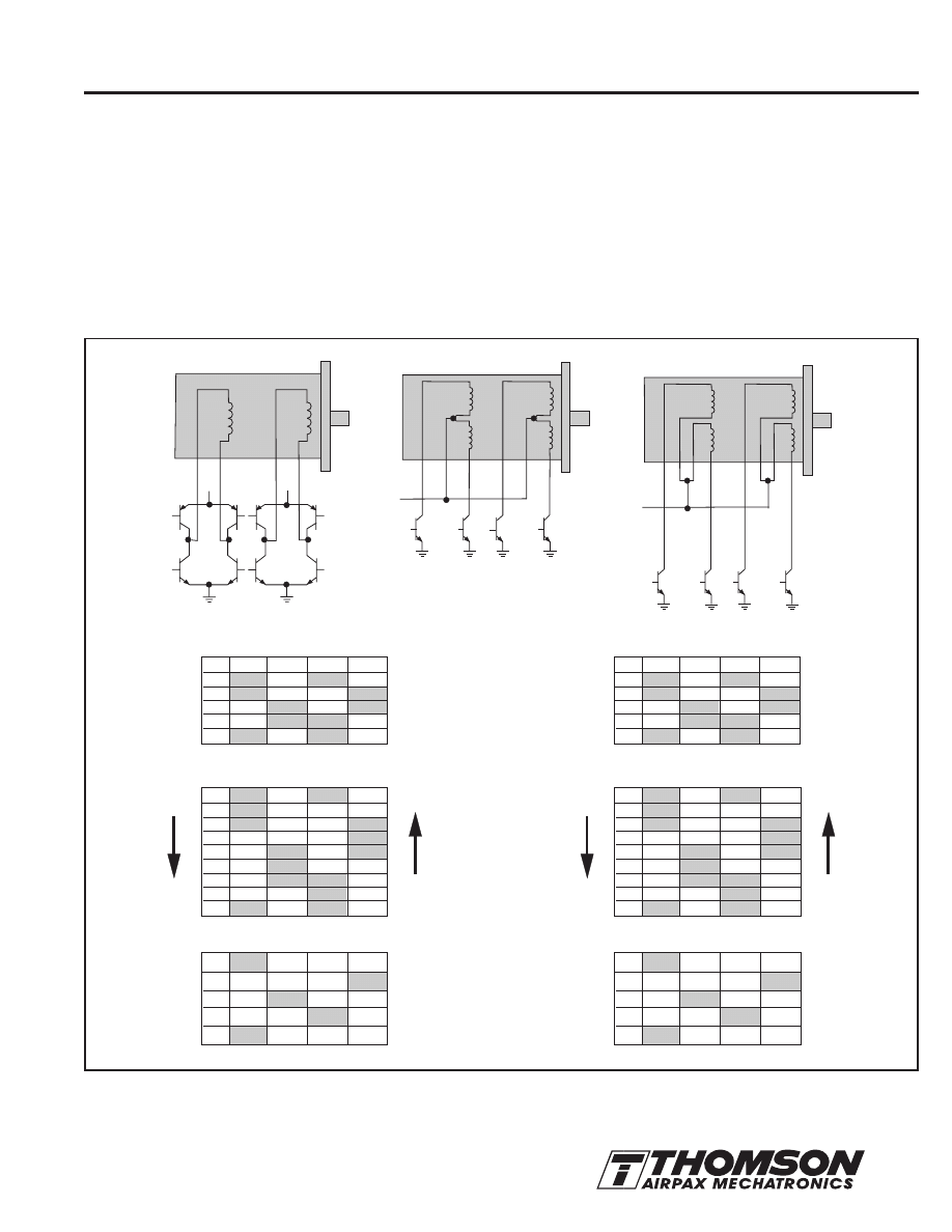
BIPOLAR AND UNIPOLAR OPERATION
All Thomson Airpax stepper motors are available with either 2-coil
Bipolar, or 4-coil Unipolar windings.
The stator flux with a Bipolar winding is reversed by reversing the
current in the winding. It requires a push-pull Bipolar drive as shown
in Fig. 14. Care must be taken to design the circuit so that the
transistors in series do not short the power supply by coming on at
the same time. Properly operated, the Bipolar winding gives the
optimum motor performance at low-to-medium step rates.
A Unipolar winding has two coils wound on the same bobbin
(one bobbin resides in each stator half) per stator half. Flux is
reversed in each coil bobbin assembly by sequentially grounding
ends of each half of the coil winding. The use of a Unipolar winding,
sometimes called a bifilar winding, allows the drive circuit to be
simplified. Not only are half as many power switches required (4 vs.
8), but the timing is not as critical to prevent a current short through
two transistors as is possible with a Bipolar drive.
For a Unipolar motor to have the same number of turns per winding
as a Bipolar motor, the wire diameter must be decreased and the
resistance increased. As a result, Unipolar motors have 30% less
torque at low step rates. However, at higher rates the torque
outputs are equivalent.
Figure 14: Schematic Bipolar and Unipolar Switching Sequence. Direction of Rotation Viewed from Shaft End.
YEL
BRN
RED
RED
RED
GRN
GR
Y
GR
Y
ORN
BLK
BLK
BLK
YEL
YEL
Q1
Q1
Q3
Q3
Q2
Q2
Q4
Q4
RED
GR
Y
Q1
Q2
+V
Q3
Q4
YEL
BLK
Q1
Q2
+V
Q3
Q4
BIPOLAR
UNIPOLAR
Normal
4-Step Sequence
/
2
Step
8-Step Sequence
Wave Drive
4-Step Sequence
1
2
3
4
5
6
7
8
1
Step
1
2
3
4
1
ON
ON
ON
OFF
OFF
OFF
OFF
OFF
ON
Q -Q
1
4
ON
ON
OFF
OFF
ON
OFF
OFF
OFF
OFF
ON
ON
ON
OFF
OFF
Q -Q
2
3
OFF
OFF
ON
ON
OFF
ON
OFF
OFF
OFF
OFF
OFF
ON
ON
ON
Q -Q
5
8
ON
OFF
OFF
ON
ON
OFF
OFF
ON
ON
ON
OFF
OFF
OFF
OFF
Q -Q
6
7
OFF
ON
ON
OFF
OFF
Step
1
2
3
4
1
Q
1
ON
ON
OFF
OFF
ON
Q
2
OFF
OFF
ON
ON
OFF
Q
3
ON
OFF
OFF
ON
ON
Q
4
OFF
ON
ON
OFF
OFF
CW
R
O
TA
T
ION
CW
R
O
TA
T
IO
N
CW
R
O
TA
T
ION
CW
R
O
TA
T
IO
N
C
C
W
RO
TA
TI
ON
1
2
3
4
1
ON
OFF
OFF
OFF
ON
OFF
OFF
ON
OFF
OFF
OFF
OFF
OFF
ON
OFF
OFF
ON
OFF
OFF
OFF
CW
R
O
TA
T
IO
N
CCW R
O
T
A
T
IO
N
1
2
3
4
1
ON
OFF
OFF
OFF
ON
OFF
OFF
ON
OFF
OFF
OFF
OFF
OFF
ON
OFF
OFF
ON
OFF
OFF
OFF
CW
R
O
TA
T
IO
N
CCW R
O
T
A
T
IO
N
CCW R
O
T
A
T
IO
N
CCW R
O
T
A
T
IO
N
CCW
R
O
T
A
T
IO
N
1
2
3
4
5
6
7
8
1
ON
ON
ON
OFF
OFF
OFF
OFF
OFF
ON
OFF
OFF
OFF
OFF
ON
ON
ON
OFF
OFF
ON
OFF
OFF
OFF
OFF
OFF
ON
ON
ON
OFF
OFF
ON
ON
ON
OFF
OFF
OFF
OFF
1
8
The specifications in this publication are believed to be accurate and reliable. However, it is the responsibility of the
product user to determine the suitability of Thomson products for a specific application. While defective products will
be replaced without charge if promptly returned, no liability is assumed beyond such replacement.
For information or to place an order in North America: 1 (203) 271-6444 Europe: (44) 1276-691622 Asia: (65) 7474-888
HIGHER PERFORMANCE
A motor operated at a fixed rated voltage has a decreasing torque
curve as the frequency or step rate increases. This is due to the fact
that the rise time of the coil limits the percentage of power actually
delivered to the motor. This effect is governed by the inductance to
resistance ratio of the circuit (L/R).
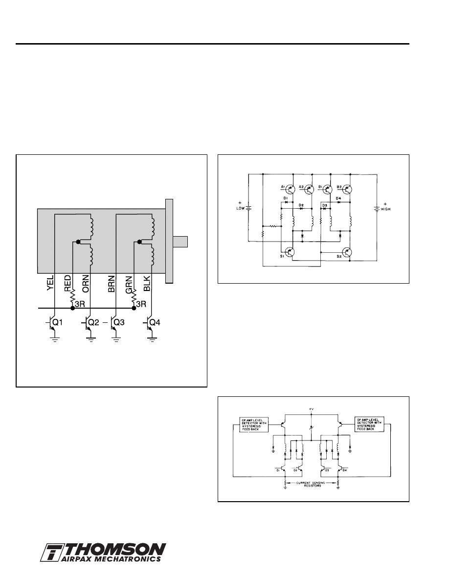
Compensation for this effect can be achieved by either increasing
the power supply voltage to maintain a constant current as the
frequency increases, or by raising the power supply voltage and
adding a series resistor in the L/4R drive circuit (See Fig. 15). Note
that as the L/R is changed, more total power is used by the system.
Figure 15: L/4R Drive
The series resistors, R, are selected for the L/R ratio desired. For
L/4R they are selected to be three times the motor winding
resistance with a wattage rating = (current per winding)
2
x R.
The power supply voltage is increased to four times motor rated
voltage so as to maintain rated current to the motor. The power
supplied will thus be four times that of a L/R drive.
Note, the Unipolar motor which has a higher coil resistance, thus
has a better L/R ratio than a Bipolar motor.
To minimize power consumption, various devices such as a bi-level
power supply or chopper drive may be used.
BI-LEVEL DRIVE
The bi-level drive allows the motor at zero steps/sec to hold at a
lower than rated voltage. When stepping, it runs at a higher than
rated voltage. It is most efficient when operated at a fixed stepping
rate. The high voltage may be switched on through the use of a
current sensing resistor, or by a circuit (See Fig. 16) which uses the
inductively generated turnoff current spikes to control the voltage.
At zero steps/sec the windings are energized with the low voltage.
As the windings are switched according to the 4-step sequence, the
suppression diodes D1, D2, D3 and D4 are used to turn on the high
voltage supply transistors S1 and S2.
Figure 16: Unipolar Bi-Level Drive.
CHOPPER DRIVE
A chopper drive maintains an average current level through the use
of a current sensor, which turns on a high voltage supply until an
upper current value is reached. It then turns off the voltage until a low
level limit is sensed, when it turns on again. A chopper is best for fast
acceleration and variable frequency applications. It is more efficient
than a constant current amplifier regulated supply. The V+ in the
chopper shown in Fig. 17 typically would be five to six times the
motor voltage rating.
Figure 17: Unipolar Chopper Drive.
9
The specifications in this publication are believed to be accurate and reliable. However, it is the responsibility of the
product user to determine the suitability of Thomson products for a specific application. While defective products will
be replaced without charge if promptly returned, no liability is assumed beyond such replacement.
For information or to place an order in North America: 1 (203) 271-6444 Europe: (44) 1276-691622 Asia: (65) 7474-888
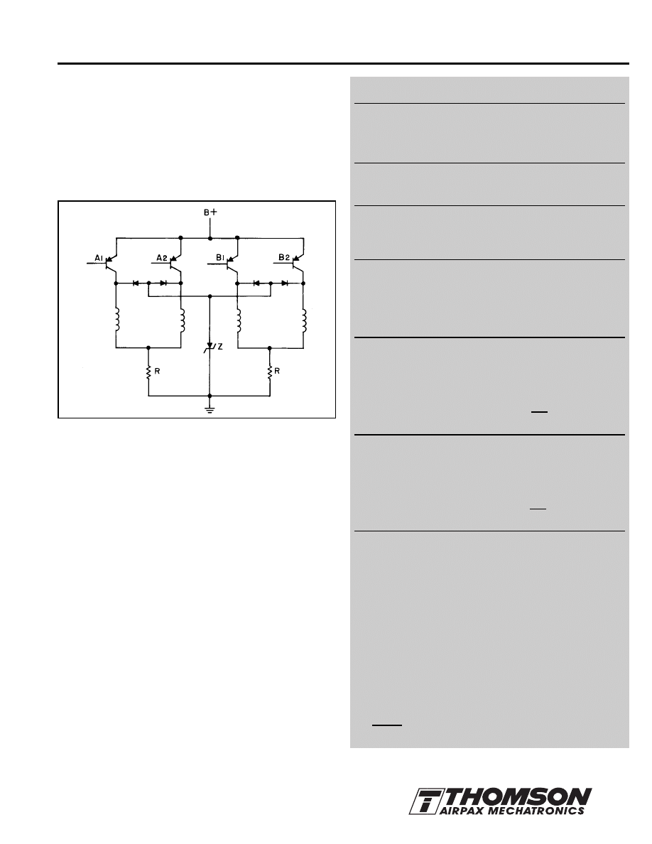
VOLTAGE SUPPRESSION
Whenever winding current is turned off, a high voltage inductive
spike will be generated, which can damage the drive circuit. The
normal method used to suppress these spikes is to put a diode
across each winding. This, however, will reduce the torque output
of the motor, unless the voltage across the switching transistors is
allowed to build up to at least twice the supply voltage. The higher
this voltage, the faster the induced field, and current will collapse,
and thus the better performance. For this reason, a zener diode or
series resistor is usually added as shown in Figure 18.
SUMMARY OF KEY TORQUE EVALUATIONS
The torque-speed characteristic curves are
key to selecting the right motor and the control
drive method for a specific application.
Define your application load.
Use the PULL IN curve if the control circuit provides
no acceleration and the load is frictional only.
Use the PULL OUT curve, in conjunction with a
Torque = Inertia x Acceleration equation (T = J
α
),
when the load is inertial and/or acceleration
control is provided.
When acceleration ramping control is provided,
use the PULL OUT curve and this torque equation:
T
J
(Torque mN•m) = J
T
x x K
When no acceleration ramping control is provided,
use the PULL OUT curve and this torque equation:
T (Torque mN•m) = J
T
x x K
Motor Selection Guidelines
1. Based on frictional torque and speed, make a first
estimate motor selection.
2. Use torque equations and motion plot to evaluate.
3. If necessary, select another motor and/or modify the drive.
4. Secure prototype and test.
Formula for determining temperature rise of a motor (using coil
resistance) is:
Motor T rise °C =
R hot (234.5 + T amb cold) - (234.5 + T amb hot)
R cold
∆
V
∆
t
v
2
2
Figure 18: Voltage Suppression Circuit.
PERFORMANCE LIMITATIONS
Increasing the voltage to a stepper motor at standstill or low
stepping rates will produce a proportionally higher torque until the
magnetic flux paths within the motor saturate. As the motor nears
saturation, it becomes less efficient and thus does not justify the
additional power input.
The maximum speed a stepper motor can be driven is limited by
hysteresis and eddy current losses. At some rate, the heating
effects of these losses limit any further effort to get more speed or
torque output by driving the motor harder.
TORQUE MEASUREMENT
The output torque of a stepper motor and drive can best be
measured by using a bridge type strain gage coupled to a magnetic
particle brake load. A simple pulley and pull spring scale also can
be used, but is difficult to read at low and high step rates.
MOTOR HEATING AND TEMPERATURE RISE
Operating continuous duty at rated voltage and current will give an
approximate 40°C motor winding a temperature rise. If the motor is
mounted on a substantial heat sink, however, more power may be
put into the windings. If it is desired to push the motor harder, a
maximum motor winding temperature of 100°C should be the upper
limit. Motor construction can be upgraded to allow for a winding
temperature of 120°C (60°C rise).
Wyszukiwarka
Podobne podstrony:
Hsi Stepper Motor Theory
5804 stepper motor driver
Minebea Stepper Motor 17pm k
Actuators and Sensors Stepper Motors Stepper Motor Operation and Theory
Minebea Stepper Motor 17pm k
23Hybrid stepper motor
Stepper Motor Basic
PORÓWNYWANIE TECHNOLOGII
19 Mikroinżynieria przestrzenna procesy technologiczne,
Technologia informacji i komunikacji w nowoczesnej szkole
Technologia spawania stali wysokostopowych 97 2003
SII 17 Technologie mobilne
W WO 2013 technologia
TECHNOLOGIA PŁYNNYCH POSTACI LEKU Zawiesiny
technologia prefabrykowana
więcej podobnych podstron