
1MRS751964-MEN
Issued:
15.03.2002
Version:
A
Program revision: 4.0
We reserve the right to change data without prior notice.
Configuring MicroSCADA for IEC
60870-5-104 Master Protocol
Configuration Guide
COM 500
Notice 1
The information in this document is subject to change without notice and should not
be construed as a commitment by ABB. ABB assumes no responsibility for any error
that may occur in this document.
Notice 2
This document complies with the program revision 4.0.
Notice 3
Additional information such as Release Notes and Last Minute Remarks can be
found on the program distribution media.
Trademarks
Microsoft is a registered trademark of Microsoft Corporation.
Windows NT is a trademark of Microsoft Corporation.
L
ON
W
ORKS
is a registered trademark of Echelon Corporation.
Other brand or product names are trademarks or registered trademarks of their respective holders.
All Microsoft products referenced in this document are either trademarks or registered trademarks of Microsoft
Corporation.


MicroSCADA Technology Manuals
SYS 500 manuals
COM 500 manuals
Application Objects
1MRS751848-MEN
Introduction to MicroSCADA Technology
1MRS751852-MUM
JAVA-API for MicroSCADA
1MRS751851-MEN
Programming Language SCIL
1MRS751849-MEN
SCIL-API for MicroSCADA
1MRS752199-MEN
Status Codes
1MRS751850-MEN
System Configuration
1MRS751846-MEN
System Objects
1MRS751847-MEN
Configuring MicroSCADA for OPC DA Client
1MRS752246-MEN
Installation
1MRS751853-MEN
Picture Editing
1MRS751854-MEN
System Management
1MRS751857-MEN
Visual SCIL Objects
1MRS751856-MEN
Visual SCIL User Interface Design
1MRS751855-MEN
COM 500 Engineering
1MRS751858-MEN
Connecting LONWORKS Devices to MicroSCADA
1MRS751845-MEN
Communication Programming Interface (CPI)
1MRS751859-MEN
Configuring MicroSCADA for DNP V3.00 Master Protocol
1MRS751860-MEN
Configuring MicroSCADA for DNP V3.00 Slave Protocol
1MRS751861-MEN
Configuring MicroSCADA for IEC 60870-5-101 Master Protocol
1MRS751862-MEN
Configuring MicroSCADA for IEC 60870-5-101 Slave Protocol
1MRS751863-MEN
Configuring MicroSCADA for IEC 60870-5-103 Master Protocol
1MRS752012-MEN
Configuring MicroSCADA for IEC 60870-5-104 Master Protocol
1MRS751964-MEN
Configuring MicroSCADA for IEC 60870-5-104 Slave Protocol
1MRS751965-MEN
Configuring MicroSCADA for Modbus Master Protocol
1MRS752242-MEN
Configuring MicroSCADA for Modbus Slave Protocol
1MRS751864-MEN
COM 500
Configuring MicroSCADA for IEC
60870-5-104 Master Protocol
Configuration Guide
1MRS751964-MEN

LIB 500 manuals
LIB 510 manuals
SMS 510 manuals
CAP 505 manuals
Common manual for LIB, CAP and SMS
LIB 500 Configuration Manual
1MRS751880-MEN
LIB 500 Operator’s Manual
1MRS751885-MUM
LIB 510 Configuration
1MRS751886-MEN
LIB 510 MV Process Configuration
1MRS751887-MEN
LIB 510 MV Process Operator’s Manual
1MRS751891-MUM
LIB 510 Operator’s Manual
1MRS751888-MUM
SMS 510 Installation and Commissioning
1MRS751897-MEN
SMS 510 Operator’s Manual
1MRS751898-MUM
CAP 505 Installation and Commissioning
1MRS751901-MEN
CAP 505 Operator’s Manual
1MRS751902-MUM
Relay Configuration Tool Tutorial
1MRS751903-MEN
Relay Mimic Editor Configuration
1MRS751904-MEN
Relay Configuration Tool Quick Start Reference
1MRS751905-MEN
SPTO Configuration Tool
1MRS751906-MEN
Protocol Editing Tool
1MRS751982-MUM
Tools for Relays and Terminals
1MRS752008-MUM
1MRS751964-MEN
Configuring MicroSCADA for IEC
60870-5-104 Master Protocol
COM 500
Configuration Guide

1
2
3
4
5
1
2
3
4
5
COM 500
Configuring MicroSCADA for IEC
60870-5-104 Master Protocol
Configuration Guide
1MRS751964-MEN


COM 500
Contents
Configuration Guide
Contents:
1. Introduction ...............................................................................9
2. Safety information ...................................................................11
3. Instructions ..............................................................................13
3.2.1. Base system configuration ...............................................13
3.2.2. Communication system configuration ..............................16
4. Technical description .............................................................31
4.2. Communication ...........................................................................33
4.2.1. Communication modes ....................................................33
4.2.2. Protocol converter ............................................................33
4.2.3. Addressing .......................................................................33
4.2.4. Device communication attributes .....................................34
4.2.5. Data in monitoring direction .............................................37
4.2.6. Data in control direction ...................................................40
4.2.7. Transparent data commands ...........................................45
4.2.8. Parameter in control direction ..........................................47
5. Appendix ..................................................................................53
5.1. Interoperability list for the 60870-5-104 master protocol .............53
5.2. Description of the SPA bus messages ........................................69
5.3. Description of parameter/byte string messages ..........................71
1MRS751964-MEN
Configuring MicroSCADA for IEC
60870-5-104 Master Protocol


COM 500
9
Configuration Guide
1. Introduction
1. Introduction
Using this manual
This manual should be read when you want to use the IEC 60870-5-104 master
protocol and need information related to it. It describes how to configure the base
system and communication system to establish communication with an IEC 60870-
5-104 slave.
In addition to this configuration, the base system is used for other communication
tasks, e.g. process communication, if needed. For information about this subject,
refer to other manuals, for example Application Objects and System Objects.
Referenced manuals
The following COM 500 manuals should be available for reference during the use
of this manual:
• Configuring MicroSCADA for IEC 60780-5-101 Master Protocol
• Configuring MicroSCADA for IEC 60780-5-104 Slave Protocol
The following MicroSCADA manuals should be available for reference during the
use of this manual:
• System Configuration manual
• System Objects manual
• Application Objects manual
Other referenced manuals
The IEC 60870-5-104 protocol is based on the following seven documents by the
IEC Technical Committee 57:
• IEC 60870-5-1
Transmission Frame Formats
• IEC 60870-5-2
Data Link Transmission Services
• IEC 60870-5-3
General Structure of Application Data
• IEC 60870-5-4
Definition and Coding of Information Elements
• IEC 60870-5-5
Basic Application Functions
• IEC 60870-5-101
Companion standard for the IEC 60870-5-101 Protocol
• IEC 60870-5-104
Companion standard for the IEC 60870-5-104 Protocol
IEC870-5-104 Master Protocol
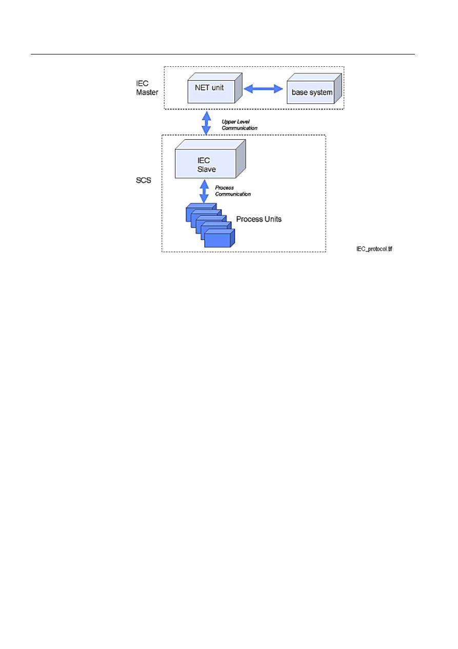
The IEC870-5-104 Master protocol is used in LAN and WAN networks to connect
central stations and substations to each other. Figure 1.-1 shows the communication
between SYS 500 and a Substation Control System (SCS). This protocol can also be
used for communication between SYS 500 and e.g. a remotely controlled line
disconnector.
1MRS751964-MEN
Configuring MicroSCADA for IEC
60870-5-104 Master Protocol
10
1MRS751964-MEN
Configuring MicroSCADA for IEC
60870-5-104 Master Protocol
COM 500
1. Introduction
Configuration Guide
)LJ 7KH,(&PDVWHUVHHVWKH6XEVWDWLRQ&RQWURO6\VWHP6&6DVDQ,(&VODYH

1MRS751964-MEN
COM 500
11
Configuring MicroSCADA for IEC
60870-5-104 Master Protocol
Configuration Guide
2. Safety information
2
2. Safety
information
This chapter gives information about the prevention of hazards.
2.1.
Backup copies
We suggest that you take backup copies before making any changes, especially the
ones that might have side effects. Software and data need to be copied to another
place, usually to a CD or backup tape. A writable CD and DAT tape are commonly
used.
Backup copying makes it easier to restore application software in case of a disk crash
or any other serious failure when stored data is lost. It is therefore recommended that
backup copies are taken regularly.
There should be at least two system backup copies and two application copies. A
new backup is copied over the oldest backup. This way the latest version is always
available, even if the backup procedure fails.
Detailed information on how to take backup copies should be delivered to the
customer with the application.
System backup
Usually a system backup is taken after the application is made. A backup should be
taken again when changes are made to the MicroSCADA system. For example, if
the driver configuration or the network set-up is changed.
Application backup
An application backup is also taken at the same time with system backup, after the
application is made. A backup should be taken again when changes are made to the
application, for example if pictures or databases are edited or new pictures are
added.
2.2.
Fatal errors
A fatal error is an error that causes a break-down or a locked situation in the
MicroSCADA program execution.
Handling
In case of a fatal error:
Write down the possible MicroSCADA error messages.
Shut down the MicroSCADA main program. If this cannot be done in the
MicroSCADA Control Panel, try to end the task in Windows NT™
1
Task
Manager.
1. Windows NT is a trademark of Microsoft Corporation.
1MRS751964-MEN

12
1MRS751964-MEN
Configuring MicroSCADA for IEC
60870-5-104 Master Protocol
COM 500
2. Safety information
Configuration Guide
Shutting down the base system computers by switching off the power might damage
the files.
In Windows NT, the data kept in the main memory at the moment of a fatal error
is placed in the drwtsn32.log file. It is placed in a system folder, for example
Winnt. Analyse and copy the data in this file.
Restart the system.
Report the program break-down together with the possible MicroSCADA error
messages and the information from the drwtsn32.log file to the MicroSCADA
supplier.
Status codes
Error messages in SCIL are called status codes. A list of status codes and short
explanations can be found in the Status Codes manual.

1MRS751964-MEN
COM 500
13
Configuring MicroSCADA for IEC
60870-5-104 Master Protocol
Configuration Guide
3. Instructions
3
3. Instructions
3.1.
General
Communication
In MicroSCADA the IEC 60870-5-104 master protocol is implemented in the PC-
NET software only. PC-NET communicates over an INTEGRATED link and via the
Ethernet ports of the base system computer. Setting the attributes of the
MicroSCADA system objects modifies the communication parameters.
The base system sees each IEC master device as a station (STA object) that has been
created to a line of a NET unit. Each IEC station works as a protocol converter that
converts data between the internal protocol of MicroSCADA and the IEC 60870-5-
104 protocol.
Requirements
The following software is required:
• MicroSCADA Software 8.4.4 or newer
• Operating system - Windows NT
3.2.
Configuration
General
The configuration can be divided into two parts:
• Base system configuration
• Communication system configuration
Configuration can be made either by using the System Configuration Tool or by
using SCIL statements. The following sections show how to make the configuration
by using SCIL. For details about the System Configuration Tool, please refer to the
System Configuration manual.
3.2.1.
Base system configuration
General
Each base system has a set of objects that specify the base system and its
environment, hardware and software, as well as the physical and logical connections
of the base system and its applications.
The base system objects are defined with SCIL commands in the
SYS_BASCON.COM file, which is executed every time the base system is started.
With a few limitations, you can also define and modify the base system objects any
time when MicroSCADA is running. During the operation, the base system objects
are in the primary memory of the base system computer.
The IEC 60870-5-104 master protocol is implemented in the PC-NET software,
which means that an INTEGRATED link must be used. The IEC 60870-5-104
master protocol uses the station type (STY object) 29.
1MRS751964-MEN

14
1MRS751964-MEN
Configuring MicroSCADA for IEC
60870-5-104 Master Protocol
COM 500
3. Instructions
Configuration Guide
Configuration steps
To configure SYS_BASCON.COM:
Define the base system.
Define a link.
Define a node.
Define a monitor.
Define an application.
Define the station type.
Define the IEC stations.
The definitions are made in the example below by using the old
SYS_BASCON.COM template. If the new (revision 8.4.3 or later) template is used,
the INTEGRATED link and the node for the PC-NET is created by the System
Configuration Tool and need not to be included in SYS_BASCON.COM. For more
information about the system objects, see the System Objects manual.
Example
The following is an example of the SYS_BASCON.COM file for communication
with the IEC 60870-5-104 master protocol. An application IEC_TEST is defined. In
this example two IEC 60870-5-104 master stations are configured.
!
It is extremely important to map the spontaneous (3) cause of transmission value as
shown in the following example, otherwise spontaneous data does not update the
process objects!
;***************************************************************************
;
; SYS_BASCON.COM
; BASE SYSTEM CONFIGURATION TEMPLATE
;
;***************************************************************************
#CREATE SYS:B = LIST(-
SA = 209,- ;STATION ADDRESS OF BASE SYSTEM
ND = 9,- ;NODE NUMBER OF BASE SYSTEM
DN = 3,- ;DEFAULT NET NODE NUMBER
DS = "RTU",- ;STA TYPES: E.G. STA,RTU,SPA,REX
FS = "NEVER")
;FILE SYNCH CRITERIA:
;NEVER,MAINT,SET,CHECKPOINT,ALWAYS
;***************************************************************************
;
; COMMUNICATION LINKS
#CREATE LIN:V = LIST(- ;REQUIRES THE PC-NET PROGRAM
LT = "INTEGRATED",-
SC = "\SC\PROG\PC_NET\PC_NETS.EXE") ;STARTUP COMMAND

1MRS751964-MEN
COM 500
15
Configuring MicroSCADA for IEC
60870-5-104 Master Protocol
Configuration Guide
3. Instructions
3
#CREATE LIN3:B = %LIN
;***************************************************************************
;
; COMMUNICATION NODES
#CREATE NOD:V = LIST(-
LI = 3,-
SA = 203)
#CREATE NOD3:B = %NOD
;***************************************************************************
;
; PRINTERS
;***************************************************************************
;
; MONITORS
#LOOP_WITH I = 1..5
#CREATE MON’I’:B = LIST(-
TT = "LOCAL",- ;TRANSLATION TYPE
DT = "X") ;X MONITOR
@MON_MAP(%I) = -1
#LOOP_END
#LOOP_WITH I = 6..10
#CREATE MON’I’:B = LIST(-
TT = "LOCAL",- ;TRANSLATION TYPE
DT = "VS") ;VISUAL SCIL MONITOR
@MON_MAP(%I) = -1
#LOOP_END
;***************************************************************************
;
; APPLICATIONS
#CREATE APL:V = LIST(-
TT = "LOCAL",- ;TRANSLATION TYPE
NA = "IEC_TEST",- ;NAME OF APPLICATION DIRECTORY
AS = "HOT",- ;APPLICATION STATE: COLD,WARM,HOT
HB = 2000,- ;HISTORY BUFFER SIZE)
RC = VECTOR("FILE_FUNCTIONS_CREATE_DIRECTORIES"),-
AP = (1,2),-
MO = %MON_MAP,- ;MONITOR MAPPING
PR = (1,2,3)) ;PRINTER MAPPING
#CREATE APL1:B = %APL
;***************************************************************************
; STATION TYPES
#SET STY29:BCX = "IEC"
#SET STY29:BCT(3) = "UNKNOWN" ; MAPPING OF SPONTANEOUS CAUSE OF TRANSMISSION
;***************************************************************************
; STATIONS
;*** NET 3 stations ***
#CREATE STA:V = LIST(-
TT = "EXTERNAL",-
ST = "IEC",-
ND = 3,-
TN = 1)

16
1MRS751964-MEN
Configuring MicroSCADA for IEC
60870-5-104 Master Protocol
COM 500
3. Instructions
Configuration Guide
#CREATE STA1:B = %STA
#CREATE STA:V = LIST(-
TT = "EXTERNAL",-
ST = "IEC",-
ND = 3,-
TN = 2)
#CREATE STA2:B = %STA
;***************************************************************************
3.2.2.
Communication system configuration
General
Each NET unit contains a set of system objects, which specify line properties,
connected devices etc. These objects can be created, modified and deleted by SCIL,
and setting the attributes of the objects can change the properties.
Access to the attributes can be one of the following:
•
5HDGRQO\: The attribute can only be read. There are still a few exceptions in
which the values can be reset.
•
:ULWHRQO\: The attribute can only be written (set).
•
5HDGFRQGLWLRQDOZULWH: The attribute can be both read and written, but the
object must be set out of use (IU = 0) before writing.
•
1ROLPLWDWLRQV: The attribute can be both read and written without limitations.
The implementation of the IEC 60870-5-104 master protocol in MicroSCADA
consists of a line object and a station object. Both of them have a specific
functionality and a set of attributes of their own. The transport interface provided by
the line object is used by the station object (i.e. application layer).
The purpose of the communication system configuration is to:
• Create all the system objects needed to establish communication between the
master and the slave.
• Adjust the values of the system object attributes to match the physical
communication channel and the properties of the slave station.
Setting the attribute values
All the line and station attributes have sensible default values but the value of each
attribute must be checked against the requirements of the actual communication
system. The attribute values depend on:
• The physical communication media (e.g. Ethernet, radio link). This affects
particularly the attributes of the line.
• The size (number of stations) of the system. This affects especially the timeout
parameters; the slower the media and bigger the system, the longer timeouts are
needed.
• The slave system. This affects both the line and station attributes, and also the
message types used.
When making the IEC connection, an agreement about the used communication
parameters should be made with the supplier or owner of the system acting as the
IEC slave.
1MRS751964-MEN
COM 500
17
Configuring MicroSCADA for IEC
60870-5-104 Master Protocol
Configuration Guide
3. Instructions
3
Unlike the IEC 60870-5-101 protocol there is no need to the define lengths of
different addresses with the IEC 60870-5-104 protocol, because it is not included in
the standard.
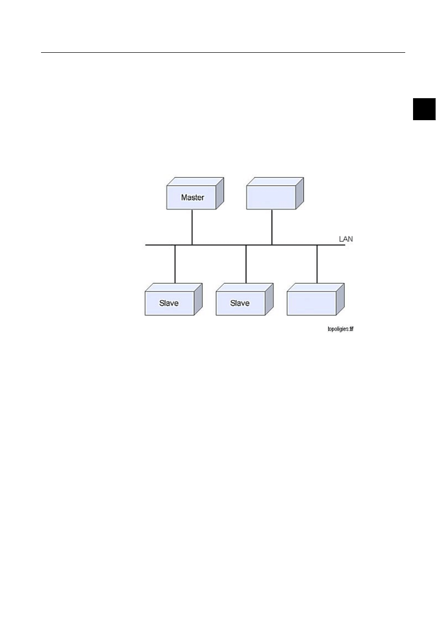
Network topology
The implementation of the IEC 60870-5-104 master protocol in MicroSCADA uses
an Ethernet connection with slave devices over LAN. The IEC 60870-5-104 master
protocol supports a multidrop technology where one master has a connection to one
or several slave devices. Figure 3.2.2.-1 illustrates the multidrop network topology.
)LJ
0XOWLGURSQHWZRUNWRSRORJ\
IEC 60870-5-104 line object
The line object of a NET unit performs the functions of the transport interface. The
purpose of the transport interface is to send and receive messages with external
devices using the IEC 60870-5-104 protocol.
According to the IEC 870 standards, the transport interface performs the following
functions:
• Provides access to the transmission medium (e.g. TCP/IP)
• Adds and removes frame delimiters if not performed by data circuit terminating
equipment
• Recognises frames addressed to a designated station
• Reports on persistent transmission errors
• Reports on the status of link configuration
• Supports initiation and maintenance functions

18
1MRS751964-MEN
Configuring MicroSCADA for IEC
60870-5-104 Master Protocol
COM 500
3. Instructions
Configuration Guide
Line object attributes
The following attributes can be used for configuring the IEC 60870-5-104 master
lines in MicroSCADA.
,8
,Q8VH
Indicates whether the line is in use (value 1) or not in use (value 0).
Data type:
Integer
Value:
0, 1
Index range:
1... 8 (NET line numbering)
Default value:
0
Access: No
limitations
32
3URWRFRO
The data transfer protocol used on the line. The line is defined to the NET by setting
this attribute. By setting the attribute to 0 the line definition including all the line
attributes will be deleted.
Data type:
Integer
Value:
0... 45
Value with IEC 60870-5-104 master protocol: 44 (Controlling
station)
Index range:
1... 8 (NET line numbering)
Access:
Read, conditional write
36%XIIHU3RRO6
L]H
Specifies the number of message buffers reserved for the line. Each buffer can
contain one message. The maximum data content length of a message is 228 bytes.
Data type:
Integer
Value:
1... 250
Index range:
1... 8 (NET line numbering)
Default value:
50
Access:
Read, conditional write
!
The value of this attribute should be greater than the number of IEC stations
configured on the line.
3'
3ROOLQJ'HOD\
The delay between the communication test polling messages U(TESTFR) (as
described in the IEC 60870-5-104 standard). If no transmission occurs within the
time specified with this attribute, the frame U(TESTFR) is sent (t3). No test poll is
sent when the value is 0.
Data type:
Integer

1MRS751964-MEN
COM 500
19
Configuring MicroSCADA for IEC
60870-5-104 Master Protocol
Configuration Guide
3. Instructions
3
Value:
0... 255
Unit:
Seconds
Index range:
1... 8 (NET line numbering)
Default value:
20 s
Access: Read,
write
+7
&RQQHFW7LPHRXW
This attribute defines the timeout of the TCP Connect operation. This attribute is
meaningful especially in multidrop configurations, since no other station is served
while the master is connecting to an unconnected station. The value of this attribute
may depend on the network structure and load, station count, etc. The value should
be defined together with the value of the ET attribute of the station object(s). Value
0 means that a blocking Connect is used. In this case, the used timeout value depends
on the used TCP/IP stack implementation.
Data type:
Integer
Value:
0-65535
Unit:
ms
Default value:
1000
Access: Read,
conditional
write
7,
5HVSRQVH7LPHRXW
The time in seconds that the IEC link waits for the end of the received message. If
no acknowledgment is received within this timeout, the station will close the
connection (t1) (as described in the IEC 60870-5-104 standard).
Data type:
Integer
Value:
1... 255
Unit:
Seconds
Index range:
1... 8 (NET line numbering)
Default value:
15 s
Access: Read,
Write
0,
0HVVDJH,GHQWLILFDWLRQ
Object address of system messages.
Data type:
Integer
Value:
1... 32760
Index range:
1... 8 (NET line numbering)
Default value:
6000 + (100 * NET number) + line number
Access: Read,
conditional
write
060HVVDJH$SSOLFDWLRQ
The number of the application that is the receiver of the system messages generated
by the line.

20
1MRS751964-MEN
Configuring MicroSCADA for IEC
60870-5-104 Master Protocol
COM 500
3. Instructions
Configuration Guide
Data type:
Integer
Value:
1... 32
Default value:
1
Index range:
1... 8 (NET line numbering)
Access:
Read, conditional write
([DPSOH
In the example of SYS_BASCON.COM earlier in this chapter, the number of the
message application is 1.
'&
'LDJQRVWLF&RXQWHUV
The line protocols gather statistical information about the events on the lines by
incrementing a number of diagnostic counters. All the major events and error
situations of the communication have their own counters.
When accessing diagnostic counters, the attribute is indexed according to the
formula:
100 * (line number) + (diagnostic counter number)
The IEC 60870-5-104 master protocol supports the following diagnostic counters:
1
Transmitted telegrams
2
Failed transmissions
3
Timeout errors
4
Transmitted I (Information) format messages
5
Transmitted S (Supervisory) format messages
6
Transmitted U (Unnumbered control function) format messages
7
Received I format messages
8
Received S format messages
9
Received U format messages
11
Received messages
12
TCP Connect count
13
TCP Accept count
14
TCP Close count
15
Duplicates and losses
16
Buffer overflow errors
Data type:
Integer
Value:
0... 30000
Index range:
See above
Access:
Read-only, the values can be reset

1MRS751964-MEN
COM 500
21
Configuring MicroSCADA for IEC
60870-5-104 Master Protocol
Configuration Guide
3. Instructions
3
IEC 60870-5-104 station object
The main purpose of the station object is protocol conversion between IEC 60870-
5-104 and the internal protocol of MicroSCADA. The station object also takes care
of application level communication with the slave.
The STA objects created in a NET unit perform the functions of the station object.
Several STA objects of the IEC device types are allowed on the same line. Some of
the station object attributes are used for configuration of the station. Others are used
for device communication. The configuration attributes are presented in this chapter
and the communication attributes in the next one.
Station object attributes
The following attributes can be used for configuring the IEC 60870-5-104 slave
stations in MicroSCADA. For compatibility reasons the attributes have been
retained from the IEC 60870-5-101 standard.
,8
,Q8VH
Indicates whether the station is in use (value 1) or not in use (value 0).
Data type:
Integer
Value:
0 or 1
Default value:
0
Access:
No limitations
/,
/LQH1XPEHU
The number of the NET line the station is connected to.
Data type:
Integer
Value:
1... 8
Default value:
1
Access:
Read, conditional write
!
Setting this attribute is not needed when the station is created by using the DV
attribute.
6$
6WDWLRQ$GGUHVV
The station address of the IEC 60870-5-104 master station, the common address of
ASDU in an IEC message.
Data type:
Integer
Value:
0... 255,
when SL attribute = 1
0... 65535,
when SL attribute = 2
Default value:
1
Access:
Read, conditional write

22
1MRS751964-MEN
Configuring MicroSCADA for IEC
60870-5-104 Master Protocol
COM 500
3. Instructions
Configuration Guide
6/
6WDWLRQ$GGUHVV/HQJWK
The length of the station address (common address of ASDU) in octets.
Data type:
Integer
Value:
1 or 2
Default value:
2
Access:
Read, conditional write
,/
,QIRUPDWLRQ$GGUHVV/HQJWK
The length of the information object address in octets.
Data type:
Integer
Value:
1… 3
Default value:
3
Access:
Read, conditional write
&/
/HQJWKRI&DXVHRI7UDQVPLVVLRQ,QIRUPDWLRQ
The length of the cause of transmission field in an IEC 60870-5-104 message in
octets.
Data type:
Integer
Value:
1 or 2
Default value:
2
Access:
Read, conditional write
!
The default values of the SL, IL and CL attributes follow the IEC standard. We
strongly recommend using these values, otherwise compatibility cannot be
guaranteed.
$/
$OORFDWLRQ
Allocates the station to an application. When the AL attribute has the value 1, the
station is reserved by the application specified by the AS attribute. All the
spontaneous messages from the station will be sent to this application.
Data type:
Integer
Value:
0 or 1
Access:
No limitations
$6$OORFDWLQJ$SSOLFDWLRQ
Specifies the allocating application of the station (see the AL attribute). The
allocating application will get all the spontaneous process data from the station. This
application is also the only one that is allowed to set the device communication
attributes.
Data type:
Integer

1MRS751964-MEN
COM 500
23
Configuring MicroSCADA for IEC
60870-5-104 Master Protocol
Configuration Guide
3. Instructions
3
Value:
0... 32
0 = no application
Access:
Read-only
!
When the AL attribute is set to 0, AS also gets the value 0.
0,
0HVVDJH,GHQWLILFDWLRQ
Object address of the system messages.
Data type:
Integer
Value:
1... 32760
Default value:
29000 + station number
Access: Read,
conditional
write
060HVVDJH$SSOLFDWLRQ
The number of the application that is the receiver of the system messages generated
by the line.
Data type:
Integer
Value:
1... 32
Default value:
1
Access: Read,
conditional
write
([DPSOH
In the example of SYS_BASCON.COM earlier in this chapter, the number of the
message application is 1.
6(
6\VWHP0HVVDJHV(QDEOHG
Specifies whether the system messages generated by NET and related to the station
are sent to the applications (value 1) or not (value 0). Using this attribute, it is
possible to disable the system messages related to the station.
Data type:
Integer
Value:
0 or 1
Default value:
1
Access: No
limitations
&$
&RPPDQG$GGUHVV
The object address of the bitstream process object in the MicroSCADA process
database, where unrecognised messages are sent.
Data type:
Integer
Value:
0 … 65534
Default value:
32000

24
1MRS751964-MEN
Configuring MicroSCADA for IEC
60870-5-104 Master Protocol
COM 500
3. Instructions
Configuration Guide
Access:
Read, conditional write
!
The unit number (UN attribute) of the bit stream process object must be the same as
the STA object number of the IEC master station.
0/
0D[LPXP0HVVDJH/HQJWK
The maximum length of transmitted message in octets.
Data type:
Integer
Value:
20…255
Default value:
230
Access:
Read, conditional write
&)
&RQ)LUPDWLRQ0RGH
The waiting of the activation termination message. With value 0, the timer length
defined with the CT attribute is not started. Value 0 is needed with some IEC60870-
5-104 slave implementations, which do not send activation termination messages at
all.
Data type:
Integer
Value:
0 = Activation termination is not waited
1 = Activation termination is waited
Default value:
1
Access:
No limitations
50
5XQQLQJ0RGH
Consists of a set of flags that control the behaviour and functionality of the IEC
master station. Each flag is one bit of this attribute. The bits are as follows (bits 1...
2 used by the IEC slave stations are left out):
Bit 0:
The hour transmission method of the events to the master. When this
bit is 0, the master gets the year, date and hour from the slave as hourly
clock synchronisation (ASDU 103). When this bit is 1, the master adds
the year, date and hour from its internal clock to the events. Minutes
and seconds should be provided in time-tagged events by the slave.
Bit 3:
Handling of the unrecognised commands. When this bit is 0,
unrecognised command messages are ignored. When this bit is 1,
unrecognised messages sent by the slave are forwarded to a bit stream
process object with an address as defined by the CA attribute.
Bit 4:
Sending of the general interrogation command when the master
receives ASDU 70. When this bit is 0, a general interrogation command
is always sent when the end of initialisation message (ASDU 70) is
received from the IEC slave. When this bit is 1, general interrogation is
not sent automatically when receiving ASDU 70.

1MRS751964-MEN
COM 500
25
Configuring MicroSCADA for IEC
60870-5-104 Master Protocol
Configuration Guide
3. Instructions
3
Bit 5:
Sending of the general interrogation command when the master gets
the zero (OK) status. When this bit is 0, a general interrogation
command is always sent when the object status of the IEC master
station gets the value zero, e.g. when set in use or after a suspension.
When this bit is 1, general interrogation is not sent automatically at zero
status.
Bit 6
Parallel commands. When this bit is 1, the sending of parallel
commands is possible. The control is returned immediately back to
SCIL and the return status of command must be checked from the
command termination process object. When this bit is 0, sending
another command is not possible before the previous command has
been completed or the confirmation timeout has occurred. This is the
default way of operation.
Bit 7
Private ASDU handling. When this bit is 1, the private range ASDUs
146, 148 and 160 are handled as unknown ASDUS. Thus, the contents
of these ASDUs are sent to a bitstream process object if the bit 3 of RM
is set. When bit 7 is 0, the ASDUs are interpreted in a following way:
ASDU 146 is similar to ASDU 30, single point
information with full time tag
ASDU 148 is similar to ASDU 31, double point
information with full time tag
ASDU 160 is similar to ASDU 37, integrated totals with
full time tag
Data type:
Integer
Value:
1... 65534, see above
Default value:
0
Access: Read,
conditional
write
([DPSOH
Enable general interrogation at zero status and disable other features, RM value =
0*8+1*16+0*32=16.
'&
'LDJQRVWLF&RXQWHUV
The values of the diagnostic counters which NET keeps for the station. The counters
have the following meaning:
1. Suspension information (0 = OK, 1 = suspended)
2. Suspension counter
3. Transmitted data messages
4. Transmitted command messages
5. Transmitted confirmation messages
6. Received data messages
7. Received command messages
8. Received confirmation messages
9. Received unknown messages
Data type:
Integer
Value:
1... 65535

26
1MRS751964-MEN
Configuring MicroSCADA for IEC
60870-5-104 Master Protocol
COM 500
3. Instructions
Configuration Guide
Index range:
1... 20
Access: Read-only
262EMHFW6
WDWXV
The current object status of the IEC slave station. When the value 1 is written to this
attribute, the slave station retransmits its current status code to the system message
process object.
Data type:
Integer
Value:
0…65535
Access:
Read-only, the values can be reset
67
6<6:DLWLQJ7LPH
The maximum time that the slave station waits for a reply from the base system.
Data type:
Integer
Value:
0... 60000
Unit:
Milliseconds
Default value:
5000
Access: No
limitations
57
$FWLYDWLRQ5HSO\7LPHRXW
The maximum time the IEC master station waits for an activation confirmation
message from the IEC slave.
Data type:
Integer
Value:
0... 255
Unit:
Seconds
Default value:
10
&7
$FWLYDWLRQ7HUPLQDWLRQ7LPHRXW
The maximum time the IEC master station waits for an activation termination
message from the IEC slave.
Data type:
Integer
Value:
0... 255
Unit:
Seconds
Default value:
60
Access: No
limitations
68
6XPPHU7LPH
States whether summer time is used or not.
Data type:
Integer
Value:
0 or 1
Default value:
0 (summertime not used)

1MRS751964-MEN
COM 500
27
Configuring MicroSCADA for IEC
60870-5-104 Master Protocol
Configuration Guide
3. Instructions
3
Access: No
limitations
,$
,QWHUQHW$GGUHVV
The IP address or the host name of the remote host. The connection is established
with a device in this address by using a port number 2404.
Value:
Any string, max 16 characters
Access: Read/write
Default:
empty string (=no address defined)
!
The line must be taken into use at least once before writing an address to this
attribute.
868QDFNQRZOHGJH6
HQG
The count of unacknowledged APDUs stored in the transport layer. The transport
layer will accept the ASDUs from the station object up to this amount before the
acknowledgement from the remote host must take place (k) (as described in the IEC
60870-5-104 standard).
Value:
1... 65535
Access:
Read/Write
Default:
12
85
8QDFNQRZOHGJH5HFHLYH
The count of unacknowledged APDUs forwarded to the station object but not yet
acknowledged to the remote host. The transport layer will receive the APDUs from
the remote host up to this amount before an acknowledgement will be sent to the
remote host (w) (as described in the IEC 60870-5-104 standard).
Value:
1... 65535
Access:
Read/Write
Default:
8
!
If you have communication problems, try to set the values of the US and UR
attributes to 1.
!
In order to get the optimised ratio for the limits of unacknowledged messages sent
to the master and received messages by the slave, the amount of the received
messages should be 2/3 of the sent messages (k/w).

28
1MRS751964-MEN
Configuring MicroSCADA for IEC
60870-5-104 Master Protocol
COM 500
3. Instructions
Configuration Guide
$7
$FNQRZOHGJH7LPHRXW
The timeout for sending an acknowledgement if the amount of APDUs defined by
the UR attribute is not received. The timer is restarted when an APDU is received
and cancelled when an acknowledge is sent (t2) (as described in the IEC 60870-5-
104 standard).
Value:
1... 255 s
Unit
Seconds
Access:
Read/Write
Default:
10 s
(7
5(FRQQHFWLQJ7LPHRXW
The interval or reconnecting attempt while communication is not established.
Value:
1... 255 s
Unit
Seconds
Access:
Read/Write
Default:
30 s
!
The value of this attribute has to be much larger than the value of the HT attribute.
Examples of communication system configuration
The following SCIL procedures make the communication system configuration
which is related to the base system configuration example presented earlier in this
document. The first procedure creates an IEC 60870-5-104 master line and two
stations on this line.
;***************************************************************************
; INPUT PARAMETERS
@NET = 3 ; NODE NUMBER OF THE PC-NET
@LINE = 1 ; LINE NUMBER
@STATIONS = (1,2) ; MASTER STATION NUMBERS
@APPLIC = 1 ; APPLICATION NUMBER
;
***************************************************************************
; CREATE A IEC 60870-5-104 MSTER LINE TO NET
#IF NET’NET’:SPO’LINE’==0 #THEN #BLOCK
#SET NET’NET’:SPO’LINE’ = 44
;IEC 60870-5-104 master
#SET NET’NET’:SPD’LINE’ = 20
;polling delay (s)
#SET NET’NET’:SMS’LINE’ = %APPLIC ;message application
#SET NET’NET’:SMI’LINE’ = %LINE+(6000+(%NET*100)) ;message identifier
#SET NET’NET’:SPS’LINE’ = 50 ;buffer pool size
#SET NET’NET’:SHT’LINE’ = 1000
;connect timeout(ms)
#SET NET’NET’:STI’LINE’ = 15 ;timeout interval (s)
#SET NET’NET’:SIU’LINE’ = 1
;Set line in use
#BLOCK_END
;***************************************************************************
; CREATE IEC 60870-5-104 MASTER STATIONS TO NET

1MRS751964-MEN
COM 500
29
Configuring MicroSCADA for IEC
60870-5-104 Master Protocol
Configuration Guide
3. Instructions
3
#LOOP_WITH I = 1..LENGTH(%STATIONS)
@STA=%STATIONS(%I)
#SET NET’NET’:SDV(29) = (%STA,%LINE);create station to line
#SET STA’STA’:SAL
= 1
;allocated
#SET STA’STA’:SAS
= %APPLIC ;allocating application
#SET STA’STA’:SMI
= 29000+%STA;message identification
#SET STA’STA’:SMS
= %APPLIC ;message application
#SET STA’STA’:SSE
= 1 ;system messages enabled
#SET STA’STA’:SSA
= %STA
;station address
#SET STA’STA’:SSL
= 2 ;station address length (bytes)
#SET STA’STA’:SIL
= 3 ;info addr. length (bytes)
#SET STA’STA’:SCL
= 2 ;COT length (bytes)
#SET STA’STA’:SCA
= 32000 ;command address
#SET STA’STA’:SST
= 5000 ;SYS waiting time (ms)
#SET STA’STA’:SRT
= 10 ;application reply timeout (s)
#SET STA’STA’:SCT
= 60 ;application termin. timeout (s)
#SET STA’STA’:SSU
= 0 ;summer time (0=no, 1=yes)
#SET STA’STA’:SML
= 230 ;max. message length
#SET STA’STA’:SRM
= 0 ;running mode
#SET STA’STA’:SIA
= ”host”
;hostname or IP address of
;the remote host
#SET STA'STA':SUS
= 12 ;unocknowledge send
#SET STA'STA':SUR
= 8 ;unacknowledge receive
#SET STA'STA':SAT
= 10 ;akcnowledge timeout (s)
#SET STA'STA':SET
= 30 ;reconnecting timeout (s)
#SET STA'STA':SIU
= 1 ;set station in use
#LOOP_END
3.3.
After configuration
For each input signal from the process devices the process database should contain
a process object whose value changes after process data is received. For each
command there should be an output process object. You should also create the bit
stream process object that receives unrecognised IEC messages from the slave.
Besides the configuration of the base and communication system you also need to
configure the IEC slave.
3.4.
How to test the configuration
When the slave and master stations have been physically tested and the
configuration has been completed, the connection and configuration can be tested
based on the following methods:
• Diagnostic counters. When the communication between the slave and the master
is running properly and data is moving on the line, the diagnostic counters
indicating the number received and transmitted data messages should be
incrementing.
• By connecting a protocol analyser supporting the IEC 60870-5-104 standard to
the line.
One advisable way to test the configuration is to use MicroSCADA also as the IEC
slave. In this case you have to make the base system and communication system
configuration for the IEC 60870-5-104 slave line and station(s). One IEC slave can
be even in the same computer.

1MRS751964-MEN
COM 500
31
Configuring MicroSCADA for IEC
60870-5-104 Master Protocol
Configuration Guide
4. Technical description
4
4. Technical
description
4.1.
General
4.1.1.
IEC 60870-5-104 Protocol
The IEC Technical Committee 57 (Working Group 03) has developed a protocol
standard for telecontrol, teleprotection, and associated telecommunications for
electric power systems. The result of this work is IEC 60870-5. The five first
documents listed in Chapter 1 specify the base of IEC 60870-5.
The IEC Technical Committee 57 has also generated a companion standard IEC
60870-5-104 for telecontrol equipment and systems with coded bit serial data
transmission in TCP/IP based networks for monitoring and controlling
geographically widespread processes. This standard utilises the series of documents
of IEC 60870-5.
The IEC 60780-5-104 protocol standard defines that transferred data entities in the
station object are equal to the ones used in the IEC 60870-5-101 protocol. The
implementation of the IEC 60870-5-104 protocol uses the same STA objects as the
IEC 60870-5-101 implementation.
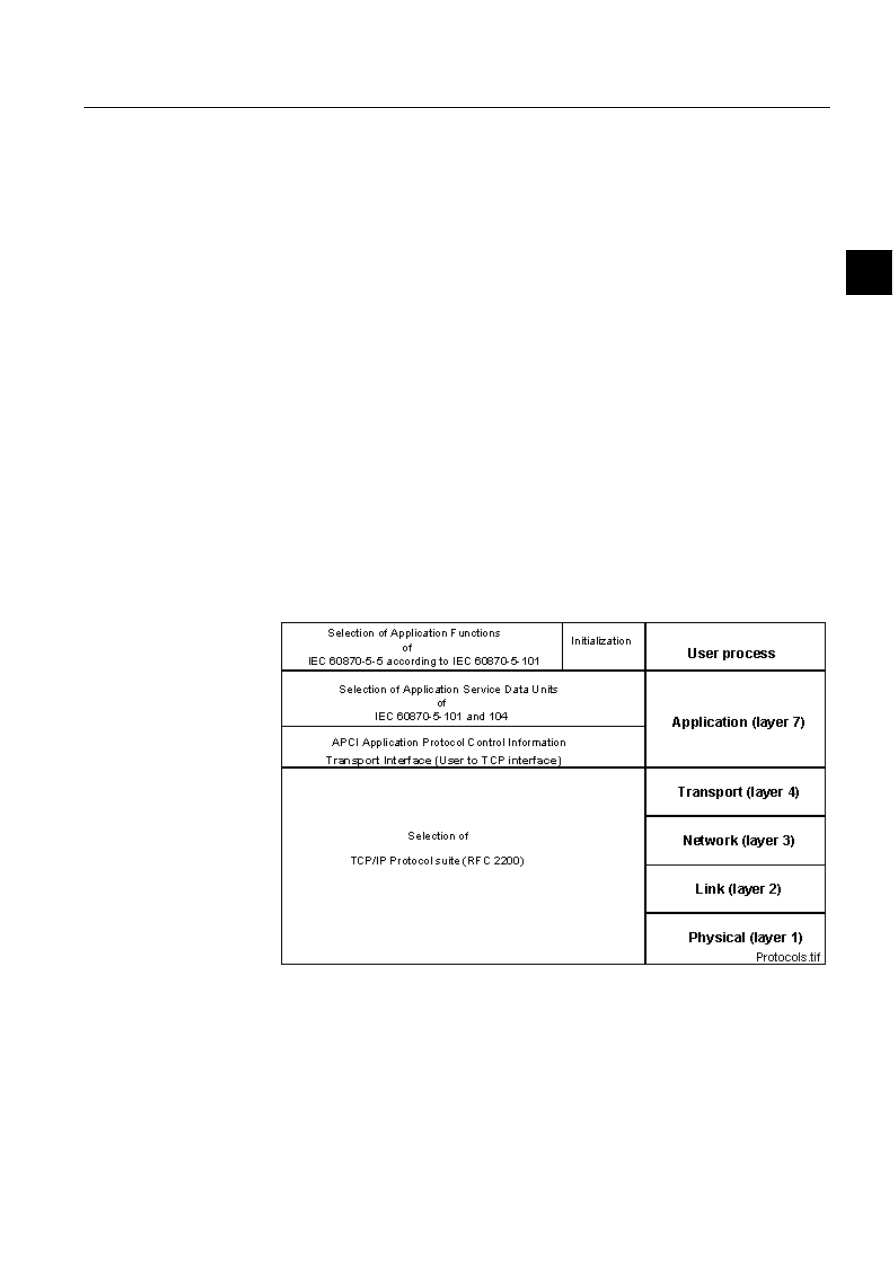
IEC 60870-5-104 is designed according to a selection of transport functions given
in the TCP/IP Protocol Suite (RFC 2200). Within TCP/IP various network types
can be utilised including X.25, FR (Frame Relay), ATM (Asynchronous Transfer
Mode), ISDN (Integrated Service Data Network), Ethernet and serial point-to-point
(X.21). Figure 4.1.1.-1 shows the protocols used in different layers.
)LJ
7KHSURWRFROVXVHGLQGLIIHUHQWOD\HUV
4.1.2.
Level of implementation
In IEC 60870-5-104 the application level messages are called Application Service
Data Units (ASDUs). Each ASDU consists of one or several information object that
contains the actual user data. MicroSCADA supports the ASDUs presented in Table
1MRS751964-MEN

32
1MRS751964-MEN
Configuring MicroSCADA for IEC
60870-5-104 Master Protocol
COM 500
4. Technical description
Configuration Guide
4.1.2-1. Private ASDUs, i.e. the ones not included in the IEC 60870-5-104
companion standard, are indicated with an asterisk (*).
Table 4.1.2-1
Application Service Data Units supported by MicroSCADA
Type id
ASDU
Description
Monitoring Direction
1
M_SP_NA_1
Single-point information without time tag
3
M_DP_NA_1
Double-point information without time tag
5
M_ST_NA_1
Step position information
7
M_BO_NA_1
Bit string of 32 bit
9
M_ME_NA_1
Measured value, normalised value
11
M_ME_NB_1
Measured value, scaled value
13
M_ME_NC_1
Measured value, short floating point number
15
M_IT_NA_1
Integrated totals
30
M_SP_TB_1
Single-point information with time tag CP56Time2a
31
M_DP_TB_1
Double-point information with time tag CP56Time2a
32
M_ST_TB_1
Step position information with time tag CP56Time2a
34
M_ME_TD_1
Measured value, normalised value with time tag
CP56Time2a
36
M_ME_TF_1
Measured value, short floating point number with time tag
CP56Time2a
37
M_IT_TB_1
Integrated totals with time tag CP56Time2a
70
M_EI_NA_1
End of initialisation
128*
M_SR_NA_1
Parameter data byte string
130*
M_SB_NA_1
101 Encapsulated SPA bus reply message
Controlling Direction
45
C_SC_NA_1
Single command
46
C_DC_NA_1
Double command
47
C_RC_NA_1
Regulating step command
48
C_SE_NA_1
Set point command, normalised value
49
C_SE_NB_1
Set point command, scaled value
50
C_SE_NC_1
Set point command, short floating point number
51
C_BO_NA_1
Bit string of 32 bit
100
C_IC_NA_1
Interrogation command
101
C_CI_NA_1
Counter interrogation command
102
C_RD_NA_1
Read command
103
C_CS_NA_1
Clock synchronisation command
105
C_RP_NA_1
Reset process command
131*
C_SR_NA_1
Parameter, byte string
133*
C_SB_NA_1
101 Encapsulated SPA bus message
Parameter in Controlling Direction

1MRS751964-MEN
COM 500
33
Configuring MicroSCADA for IEC
60870-5-104 Master Protocol
Configuration Guide
4. Technical description
4
For further details, see the IEC 60870-5-104-interoperability list for MicroSCADA
in the end of this document.
4.2.
Communication
This chapter gives a more detailed description of the implementation of the IEC
60870-5-104 master protocol in MicroSCADA. The attributes that can be used for
device communication are also described. Examples of how to exchange data
between the master and the slave are given in this chapter along with information of
the IEC 60870-5-104 status codes.
4.2.1.
Communication modes
The IEC 60870-5-104 protocol has only one mode or line object transmission
procedure compared to IEC 60870-5-101: balanced mode, where each station,
master and slave may initiate message transfers. The master may keep several
connections to controlled stations at the same time.
4.2.2.
Protocol converter
Each IEC 60870-5-104 master station configured on a line of a NET unit acts as a
protocol converter between the IEC 60870-5-104 protocol and a base system. An
internal protocol of MicroSCADA is used in communication between the
MicroSCADA nodes, for example, between a base system and a NET unit.
In IEC 60870-5-104 the data sent from the slave to the master can be divided in two
classes: class 1 or class 2. Data in class 1 is sent with higher priority than class 2 data.
4.2.3.
Addressing
In IEC 60870-5-104 there are two kinds of addresses:
•
6WDWLRQDGGUHVV:a common address of an ASDU. There can be several common
addresses of an ASDU with the same link address. This address is defined by the
SA (Station Address) attribute of the IEC station.
•
6LJQDODGGUHVV:aninformation object address. This address is unique for each
signal with the same common address of an ASDU. The Information object
address can be given in two ways:
• As an unstructured address, which is basically just an integer within the range
of the information object address.
• As a structured address which is given byte-wise so that each byte usually
represents a level in a hierarchical structure. For example, upper byte = unit
number and lower byte = signal address.
MicroSCADA supports only unstructured addresses. However, this does not prevent
communication with the IEC slaves by using structured addresses, since the two
110
P_ME_NA_1
Parameter of measured values, normalised value
111
P_ME_NB_1
Parameter of measured values, scaled value
112
P_ME_NC_1
Parameter of measured values, short floating point no.
113
P_AC_NA_1
Parameter activation
Type id
ASDU
Description

34
1MRS751964-MEN
Configuring MicroSCADA for IEC
60870-5-104 Master Protocol
COM 500
4. Technical description
Configuration Guide
types of addresses just demonstrate two different ways of presenting the same
address. For example, a two-byte address can be represented as follows:
unstructured = 256*upper byte + lower byte.
In MicroSCADA both the input and output process objects share the same address
range, which means that there cannot be two process objects with overlapping
addresses. If the user wants this feature, e.g. a command and the corresponding
indication having the same address, it can be achieved by using offsets that are
outside the information address range limited by the IL attribute. The offset used
must be large enough to set only the bits of the information object address that are
more significant than the bits within the IL range.
Note that the length of station address, cause of transmission and information object
address have been possible to define with different values. This is still possible with
the SL, CL and IL attributes for special circumstances. However, the IEC 60870-5-
104 standard defines the exact lenghts of these fields. They are set to default values
when a STA object is created and they cannot be changed without a reason. The
default values are 2 for the station address, 2 for the cause of transmission and 3 for
the information object address.
([DPSOH
(bits numbered from 0 to 23)
STAn:SIL = 3, 24 bit addresses
Information object address 2000 (decimal) = 0000000000000011111010000
(binary)
Offset = 131072 (decimal) = 10000000000000000000000000 (binary), sets
bit 24
Address for indication = 2000 (decimal) = 0000000000000011111010000
(binary)
Address for command = 2000 + 131072 = 133072 (decimal) =
0000000000000011111010000 (binary)
4.2.4.
Device communication attributes
*,
*HQHUDO,QWHUURJDWLRQ
Setting this attribute sends a general/group interrogation command (ASDU 100) to
the IEC slave station. In IEC 60870-5-104 analog and binary data can be divided into
16 groups, which can then be interrogated separately. General interrogation covers
all groups.
By setting 1 to the GI attribute a general interrogation message is generated. By
using the vector value, an interrogation command can be deactivated, i.e. cancelled,
or a group interrogation command is generated.
Data type:
Vector or integer
Value:
Vector (ENA,[QOI]) or integer 1
Access: No
limitations

1MRS751964-MEN
COM 500
35
Configuring MicroSCADA for IEC
60870-5-104 Master Protocol
Configuration Guide
4. Technical description
4
'HVFULSWLRQRIWKHYHFWRUSDUDPHWHUV
ENA:
Activate (value 1) or deactivate (value 0) interrogation
QOI:
Qualifier of interrogation
Value 20:
General interrogation
Values 21…36:
Interrogation for groups 1…16
6<
6\QFKURQLVH
The SY attribute is used to make an accurate time synchronisation of IEC stations.
No time arguments are needed since the time sent in the synchronisation message is
taken from the internal clock of MicroSCADA.
Clock synchronisation may be used in configurations where the
PD[LPXPQHWZRUN
GHOD\ is less than the required accuracy for the clock in the receiving station. For
example, if the network provider guarantees that the delay in the network will be no
more than 400 ms (a typical X.25 WAN value) and the required accuracy in the
controlled station is 1 second, the clock synchronisation procedure is useful.
Data type:
Vector
Value:
Vector (COT, [BRO,[ADDR]])
Access: Write-only
'HVFULSWLRQRIWKHYHFWRUSDUDPHWHUV
COT:
Cause of transmission of the synchronisation messages. Valid
values: 6 = activate, 8 = deactivate.
BRO:
Determines the type of the synchronisation message. Station
specific synchronisation is used and the value should always be
0. If omitted, value 0 is assumed.
ADDR:
Information object address of the synchronisation message. In
most cases value 0 is correct. If omitted, value 0 is assumed.
&2
&RPPDQG2XW
The CO attribute can be used for generating command messages to IEC stations. All
kinds of commands can be generated: data commands, application commands and
system commands. Parameters in the command direction are also sent by using the
CO attribute.
The data content of the command, which in the IEC standards is called a set of
information objects, is given as transparent data, octet by octet. It must be noted that
the user is responsible for the validity of the data content. For more information,
please refer to the IEC standards listed in Chapter 1.
Data type:
Vector
Value
Vector (TYPE, ADDR,COT,DATA)
Value range:
0...255,
when IL attribute = 1
0...65535,
when IL attribute = 2
0...16777215,
when IL attribute = 3 (used in IEC
60870-5-104)
Access: Write-only

36
1MRS751964-MEN
Configuring MicroSCADA for IEC
60870-5-104 Master Protocol
COM 500
4. Technical description
Configuration Guide
'HVFULSWLRQRIWKHYHFWRUSDUDPHWHUV
TYPE:
Type identification of the ASDU, integer. This parameter can be
a type identification given in the IEC 60870-5-104 companion
standard or a private one. Examples of type identifications of
command messages are given in the table below.
Table 4.2.4-1
Examples of type identifications of command messages
ADDR:
Information object address of the command, integer.
COT:
Cause of transmission of the message, integer. This parameter
describes the reason why a message is sent. The causes of
transmission shown in Table 4.2.4-2 are valid when using the
CO attribute.
Table 4.2.4-2
The causes of transmission valid for the CO attribute
DATA:
The set of information objects of the command as integers. Each
integer corresponds to one octet in the IEC message.
A few examples of the use of the CO attribute are presented below. See also the
examples of the data, application and system commands later in this document.
Type id
ASDU
Description
45
C_SC_NA_1
Single command
46
C_DC_NA_1
Double command
47
C_RC_NA_1
Regulating step command
48
C_SE_NA_1
Set point command, normalised value
49
C_SE_NB_1
Set point command, scaled value
50
C_SE_NC_1
Set point command, short floating point number
51
C_BO_NA_1
Bit string of 32 bit
100
C_IC_NA_1
Interrogation command
101
C_CI_NA_1
Counter interrogation command
102
C_RD_NA_1
Read command
103
C_CS_NA_1
Clock synchronisation command
105
C_RP_NA_1
Reset process command
110
P_ME_NA_1
Parameter of measured values, normalised value
111
P_ME_NB_1
Parameter of measured values, scaled value
112
P_ME_NC_1
Parameter of measured values, short floating point no.
113
P_AC_NA_1
Parameter activation
133
C_SB_NA_1
101 Encapsulated SPA bus message
COT
Description
3
Spontaneous
5
Request
6
Activation
8
Deactivation

1MRS751964-MEN
COM 500
37
Configuring MicroSCADA for IEC
60870-5-104 Master Protocol
Configuration Guide
4. Technical description
4
;general interrogation
#SET STA’STA_NR’:SCO = (100,0,6,20)
;close select command, double command, address 1000
#SET STA’STA_NR’:SCO = (46,1000,6,128+1)
;test command
#SET STA’STA_NR’:SCO = (104,0,6,170,85)
7'
7UDQVSDUHQW'DWD
The TD attribute is used for sending transparent data (e.g. SPA messages) to the IEC
slave.
Data type:
Vector
Value
Vector (TYPE, ADDR, COT, TDT)
Value range:
0...255,
when IL attribute = 1
0...65535,
when IL attribute = 2
0...16777215,
when IL attribute = 3 (used in IEC 60870-5-
104)
Access: Write-only
'HVFULSWLRQRIWKHYHFWRUSDUDPHWHUV
TYPE:
Type identification of the ASDU, integer. The type
identifications shown in Table 4.2.4-3 are allowed when
transparent data is sent to the IEC slave by using the TD
attribute.
Table 4.2.4-3
The type identifications allowed when using the TD attribute
ADDR: Information
object
address,
integer
COT:
Cause of transmission of the message, integer. Valid value: 7 =
activation confirmation
TDT:
Transparent data (e.g. SPA message) as a text string
For more detailed information see the examples and the interoperability list later in
this document.
4.2.5.
Data in monitoring direction
Data in monitoring direction, i.e. from the slave to the master, is received in IEC type
process objects. Data in monitoring direction includes, for example, double
indications and measured values. The relation between the IEC 60870-5-104
ASDUs and MicroSCADA process object types is presented in Table 4.2.5-1:
Type id
ASDU
Description
131
C_SR_NA_1
Parameter, byte string
133
C_SB_NA_1
101 Encapsulated SPA bus message

38
1MRS751964-MEN
Configuring MicroSCADA for IEC
60870-5-104 Master Protocol
COM 500
4. Technical description
Configuration Guide
Table 4.2.5-1
Relations between the MicroSCADA process object types and
IEC 60870-5-104 ASDUs
Both static data (non-time-tagged data) and events (time-tagged data) with the
same information object address are received in the same process object. When
MicroSCADA receives an IEC message, the process object attributes in Table
4.2.5-2 are updated based on the information in the IEC message:
Table 4.2.5-2
Process object attributes updated from an IEC message
For each information object in an IEC ASDU there is a qualifier octet that consists
of a set of qualifier descriptor bits each of which indicate a property of the
information object. Each qualifier descriptor bit updates a process object attribute as
shown in Table 4.2.5-3. The whole qualifier octet is set to the QL attribute of the
process object. The qualifier descriptor bits and their descriptions along with related
process object types are given in the table below.
Type id
Description
Process Object Type
1, 30
Single point information
Binary input
3, 31
Double point information
Double binary input
5, 32
Step position information
Analog input
9, 11, 13, 34,
36
Measured value
Analog input
15, 37
Integrated totals
Pulse counter
7
32-bit bitstring
Bit stream
Attribute
Values
Description
TY
0... 44
Type identification of the ASDU.
OV
-
Value of the information object. Data type depends on the
ASDU.
OS
0... 10
Object status, calculated from the qualifier descriptor bits
of the information objec.t
QL
0... 255
Qualifier byte of the information objec.t
IV
0, 1
Invalid bit of the qualifier.
NT
0, 1
Not topical bit of the qualifier.
BL
0, 1
Blocked bit of the qualifier.
SB
0, 1
Substituted bit of the qualifier.
OR
0, 1
Overflow bit of the qualifier. Only with analog input process
objects.
OF
0, 1
Counter overflow bit of the qualifier. Only with pulse
counter process objects.
CT
0…63
Cause of transmission of the message.
OG
0...255
Originator address of the message.
RT
Time
Time tag of the information object (time-tagged data), or
system time (non-time-tagged data).
RM
0…999
Milliseconds of the information object (time-tagged data),
or system time (non-time-tagged data).

1MRS751964-MEN
COM 500
39
Configuring MicroSCADA for IEC
60870-5-104 Master Protocol
Configuration Guide
4. Technical description
4
Table 4.2.5-3
Qualifier descriptor bits
A time stamp sent from the IEC slave contains a status bit where the slave can mark
the time stamp as invalid. Usually this means that the slave should be synchronised
by the master. The value of the OS (Object Status) attribute of an input process
object is calculated from the qualifier descriptor bits as in the following:
if IEC_
,9then
(*invalid bit set*)
OS := 1
elsif IEC_
17 then
(*not topical bit set*)
OS := 2
elsif IEC_Timetag_
,9 then(*time invalid bit set*)
OS := 3
end_if
The following sections give a brief description of each MicroSCADA input process
object type and the corresponding IEC ASDUS.
Binary inputs and double binary inputs
Single indications (ASDUs 1 and 30) are received by binary input, and double
indications (ASDUs 3 and 31) by double binary indication process objects. Note that
in MicroSCADA the double indication values 1 and 2 are reverse compared to the
ones in the IEC message in order to make them equal to the double binary values of
other master protocols implemented in MicroSCADA.
Bit
Name
Description
Process Object
Type
IV
Invalid
A value is valid if it was correctly acquired. After
the acquisition function recognises abnormal
conditions of the information source (missing or
non-operating updating devices), the value is then
marked invalid. The value of the information object
is not defined under this condition. The mark
Invalid is used to indicate to the master that the
value may be incorrect and cannot be used.
All
NT
Not topical
A value is topical if the most recent update was
successful. It is not topical if it was not
successfully updated during a specified time
interval or it is unavailable.
All
SB
Substituted
The value of the information object is provided by
input of an operator (dispatcher) or by an
automatic source.
All
BL
Blocked
The value of the information object is blocked for
transmission; the value remains in the state that
was acquired before it was blocked. Blocking and
deblocking may be initiated e.g. by a local lock or a
local automatic cause.
All
CA
Counter
adjusted
Counter was/was not adjusted since the last
reading.
PC
OV
Overflow
The value of the information object is beyond a
predefined range of value (mainly applicable to
analogue values).
AI
CY
Carry
Counter overflow occurred/did not occur in the
corresponding integration period.
PC

40
1MRS751964-MEN
Configuring MicroSCADA for IEC
60870-5-104 Master Protocol
COM 500
4. Technical description
Configuration Guide
Analog inputs and digital inputs
Measured values (ASDUs 9, 11, 13, 34 and 36) and step position information
(ASDUs 5 and 32) can be received by analog input process objects. The value ranges
of the ASDUs are as shown in Table 4.2.5-4.
Table 4.2.5-4
Value ranges of measured value and step position ASDUs
If the value of the measured value sent from the IEC slave is larger than the value
range of the ASDU, the value is limited to the range and the overflow bit of the
quality descriptor is set. This bit is sent to the OR attribute of the process object.
Step position information can also be received by digital input process object. Note
that the value range of the step position information is larger in SCIL since it also
contains the transient state bit, which is the second most significant bit of the octet.
Pulse counters
Integrated totals (ASDUs 14 and 37) can be received by pulse counter process
objects. In IEC 60870-5-104 pulse counters are 32-bit counters, which have a 5-bit
sequence number as the five least significant bits of their qualifier octet. The
qualifier octet is set to the QL attribute of the process object.
Bit streams
32-bit strings (ASDU 7) and transparent data (ASDUs 130 and 133) can be
received by bit stream process objects. The message can be converted to an integer
vector by using the UNPACK_STR function or to text by using the TYPE_CAST
function, see the example below:
;convert an unrecognized IEC message to a vector of bytes and find ASDU id
@IEC_MSG = UNPACK_STR(‘LN’:POV’IX’,8)
@ASDU_ID = %IEC_MSG(3)
;convert a transparent SPA reply message to text
@SPA_MSG = TYPE_CAST(‘LN’:POV’IX’,”TEXT”)
A special case of the IEC bit stream objects is the one receiving unrecognised
messages from the IEC slave. The address of this process object is the same as the
CA attribute of the IEC master station.
4.2.6.
Data in control direction
Data that is sent from the IEC master to one or more IEC slaves is called data in
control direction. This data includes the data command, application command and
system command messages. These messages are described in this section.
Type id
Value type
Value range
Value in MicroSCADA
5, 32
Step position
–64...63
Integer –128…127
9, 34
Normalised
-1…(1-2^-15)
Integer –32768…32767
11
Scaled
–32768…32767
Integer –32768…32767
13, 36
Short floating point 32-bit float
Real

1MRS751964-MEN
COM 500
41
Configuring MicroSCADA for IEC
60870-5-104 Master Protocol
Configuration Guide
4. Technical description
4
4.2.6.1.
Command handling in IEC 60870-5-104 protocol
Command confirmation
The IEC 60870-5-104 protocol includes the concept of command confirmations.
Basically a confirmation is a message sent by the slave indicating that a command
has been received, executed or rejected. Commands are confirmed in two steps as
follows:
• A command is
FRQILUPHG when it is received. An activation confirmation can be
positive (command accepted) or negative (command rejected). The status
ICCC_NEGATIVE_CONFIRMATION indicates of the latter.
• A command is
WHUPLQDWHG when its execution is finished. An activation
termination can be positive (command successfully completed) or negative
(command failed).
The following exceptions apply:
• Select-type data commands and reset process commands (ASDU 105) are only
confirmed, not terminated.
• Clock synchronisation commands (ASDU 103) and read commands (ASDU 102)
are not confirmed or terminated.
Confirmation and termination messages can be received by analog input or IEC
command termination process objects with the UN attribute equal to the STA object
number of the IEC master station and the OA attribute equal to command address +
offset. Offset is 1000000 hexadecimal = 16777216 decimal. The OV attribute of the
process object provides the following information presented in Table 4.2.6.1-1:
Table 4.2.6.1-1
Values of the process object receiving activation
confirmations and terminations
The length of the activation confirmation and termination timeouts is determined by
the RT and CT attributes of the IEC master station, respectively.
Command transactions
In the MicroSCADA implementation of the IEC 60870-5-104 master protocol one
command transaction can be open at the same time. This means that while an IEC
master station waits for a termination to a data, application or system command, a
new command cannot be issued. The status
13867 ICCC_CONFIRMATION_OF_CMD_IS_NOT_READY
is returned in this situation.
If the RM attribute bit 6 is set, the user can execute parallel commands without need
to wait for confirmation of foregoing commands. The result of the executed
command can be read from the process object with command confirmation offset.
Values
Description
0
Positive activation confirmation or termination
1
Negative activation confirmation
2
Activation confirmation timeout
3
Activation termination timeout
4
Negative activation termination

42
1MRS751964-MEN
Configuring MicroSCADA for IEC
60870-5-104 Master Protocol
COM 500
4. Technical description
Configuration Guide
4.2.6.2.
Data commands
Object commands
Object commands (e.g. switching device open/close commands, tap changer raise/
lower commands) including the ASDUs shown in Table 4.2.6.2-1 are sent to the IEC
slave by setting a binary output process object or by using the CO attribute of the
IEC station. The unit number (UN attribute) of the output process object must be the
same as the STA object number of the corresponding IEC master station. The
address of the process object must also equal to the address of the command in the
IEC slave. IEC object commands are usually select-before-execute commands.
Table 4.2.6.2-1
Object command ASDUs
The value set to the process object is a list of attributes. The attributes included in
the list are shown in Table 4.2.6.2-2. Optional attributes are indicated with an
asterisk (*).
Table 4.2.6.2-2
Process object attributes included in an IEC object
command
([DPSOHV
;single command, select off, short pulse
#SET ’LN’:PSE’IX’ = LIST(OV=0,CT=6,OG=100,TY=45,QL=1)
;single command, execute offn, short pulse
#SET ’LN’:POV’IX’ = LIST(OV=0,CT=6,OG=100,TY=45,QL=1)
;single command, cancel (deactivate) off, short pulse
#SET ’LN’:POV’IX’ = LIST(OV=0,CT=8,OG=100,TY=45,QL=1)
;double command, execute on, long pulse
#SET ’LN’:POV’IX’ = LIST(OV=1,CT=6,OG=100,TY=46,QL=2)
Type id
Description
Process Object Type
45
Single command
Binary output
46
Double command
Binary output
47
Regulating step commands
Binary output
48...50
Set point command
Analog output
Attr.
Values
Default
Description
SE
-
-
If select command is sent, the parameter list is set to
the SE attribute. Otherwise excluded.
TY
45... 47
-
Type identification of the ASDU.
OV
0,1,2
-
Value of the command 0 = off, 1 = on (single
command, double command), 0 = lower, 1 = higher
(regulating step command).
QL*
0... 255
0
Qualifier of the command: 0 = do definition, 1 = short
pulse, 2 = long pulse, 3 = persistent output.
CT
6, 8
-
Cause of transmission of the command: 6 = activate,
8 = deactivate.
OG*
0... 255
0
Originator address of the command.
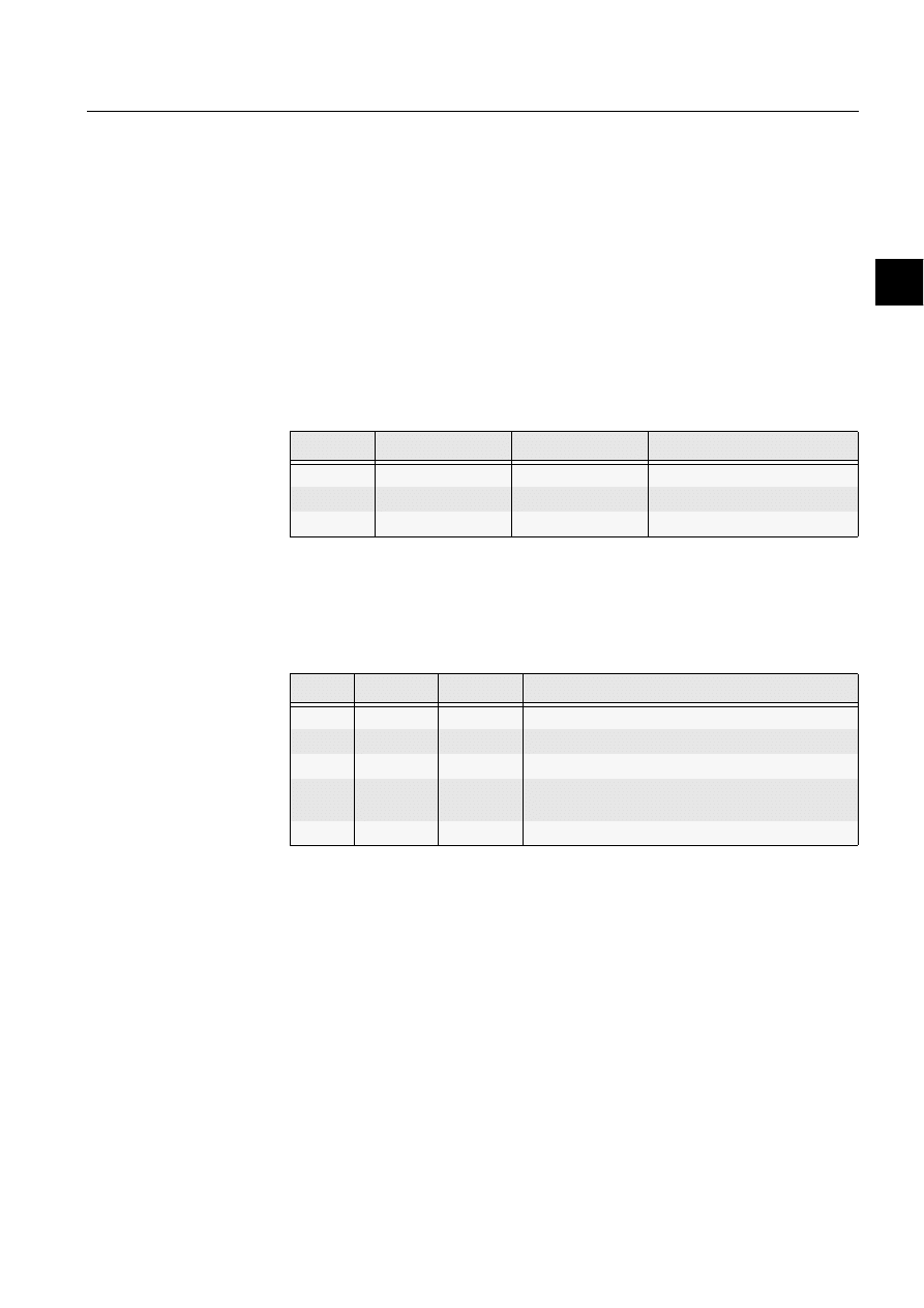
1MRS751964-MEN
COM 500
43
Configuring MicroSCADA for IEC
60870-5-104 Master Protocol
Configuration Guide
4. Technical description
4
;regulating step command, execute lower, persistent output
#SET ’LN’:POV’IX’ = LIST(OV=0,CT=6,OG=100,TY=47,QL=3)
Analog setpoints
Analog setpoints (ASDUs 48, 49 and 50) can be sent by using the CO attribute or by
setting an analog output process object. The unit number (UN attribute) of the
process object must be the same as the STA object number of the corresponding IEC
slave station. The address of the process object must also equal to the address of the
command in the IEC slave. IEC setpoint commands are usually direct (only execute
sent) commands.
There are three different types of analog setpoint values presented in Table 4.2.6.2-
3. Note that both the normalised and scaled values are handled as signed 16-bit
integers in MicroSCADA.
Table 4.2.6.2-3
Value ranges of setpoint ASDUs
The value set to the process object is a list of attributes. The attributes included in
the list are shown in Table 4.2.6.2-4. Optional attributes are indicated with an
asterisk (*).
Table 4.2.6.2-4
Process object attributes included in an IEC setpoint
command
([DPSOHV
;normalised setpoint command, execute
#SET ’LN’:POV’IX’ = LIST(OV=5000,CT=6,OG=100,TY=48,QL=0)
;scaled command, cancel (deactivate)
#SET ’LN’:POV’IX’ = LIST(OV=100,CT=8,OG=100,TY=49,QL=0)
4.2.6.3.
Application commands
Application commands include the ASDUs shown in Table 4.2.6.3-1. All the
application commands are sent with address zero.
Type id
Value type
Value range
Value in MicroSCADA
48
Normalised
-1…(1-2^-15)
Integer –32768... 32767
49
Scaled
–32768... 32767
Integer –32768... 32767
50
Short floating point
32-bit float
Real
Attr.
Values
Default
Description
TY
48... 50
-
Type identification of the ASDU
OV
0,1,2
-
Value of the command depending on the ASDU
QL*
0... 255
0
Qualifier of the command (no standard definitions yet)
CT
6, 8
-
Cause of transmission of the command: 6 = activate,
8 = deactivate
OG*
0... 255
0
Originator address of the command

44
1MRS751964-MEN
Configuring MicroSCADA for IEC
60870-5-104 Master Protocol
COM 500
4. Technical description
Configuration Guide
Table 4.2.6.3-1
IEC 60870-5-104 application commands
General interrogation command
When the IEC slave station receives a general interrogation command (ASDU 100)
from the master, it must send all the input signals (except pulse counters) to the
master without time tag. The cause of transmission is set to 20. IEC 60870-5-104
includes also a group interrogation function. When this function is used, the signals
sent to the IEC master are divided into groups which can be interrogated one at the
time. The cause of transmission is set to 20 + group number. Interrogation
commands can be sent by using the GI or CO attributes of the IEC master station as
shown in the examples below.
;activate general interrogation
#SET STA’STA_NR’:SGI = 1
;activate group interrogation
@GROUP = 1 ; 1..16
#SET STA’STA_NR’:SCO = (100,0,6,20+%GROUP)
Counter interrogation command
The counter interrogation command is like a general interrogation but only for the
integrated totals (pulse counters). A counter interrogation can also be a group
interrogation; in this case the number of the groups is four. The cause of
transmission of the interrogated pulse counters is 37 in case of a counter
interrogation or 37 + group number in case of a group counter interrogation. A
counter interrogation command can be sent by using the CO attribute as shown
below:
;activate counter interrogation
#SET STA’STA_NR’:SCO = (101,0,6,0)
;activate group counter interrogation
@GROUP = 1 ; 1..4
#SET STA’STA_NR’:SCO = (101,0,6,%GROUP)
Read command
By using the read command (ASDU 102) the user can request the value of an
individual signal from the IEC master. The requested signal is sent with the cause
of transmission value 5. Note that pulse counters are not included in the read
command. A read command can be sent by using the CO attribute as shown below:
;read of user data command
@ADDR = 255 ; information object address
#SET STA’STA_NR’:SCO = (102,%ADDR,5,0)
Type id
ASDU
Description
100
C_IC_NA_1
Interrogation command
101
C_CI_NA_1
Counter interrogation command
102
C_RD_NA_1
Read command
105
C_RP_NA_1
Reset process command

1MRS751964-MEN
COM 500
45
Configuring MicroSCADA for IEC
60870-5-104 Master Protocol
Configuration Guide
4. Technical description
4
Reset process command
The purpose of the reset process command (ASDU 105) is to re-initialise the
application level of the IEC slave station. It can be sent by using the CO attribute as
shown below:
;activate reset process command
#SET STA’STA_NR’:SCO = (105,0,6,0)
4.2.6.4.
System commands
System commands include the ASDUs presented in Table 4.2.6.4-1. All the
application commands are sent with address zero by default. The address of the
clock synchronisation command can be changed by using the ADDR parameter of
the SY (Synchronise) attribute.
Table 4.2.6.4-1
IEC 60870-5-104 system command ASDU
Clock synchronisation command
The clock synchronisation commands (ASDU 103) are used for synchronising the
IEC slave stations. This command can be sent by using the SY attribute of the IEC
master station as shown below:
;activate broadcast synch
#SET STA’STA_NR’:SSY = (6,1)
;deactivate synch to one station
#SET STA’STA_NR’:SSY = (8,0)
4.2.7.
Transparent data commands
It is possible to exchange transparent messages between a MicroSCADA IEC slave
and an IEC master. An example of this kind of messages could be SPA messages.
Transparent SPA messages are sent as commands to the slave by using the TD
attribute of the IEC master station and received in a bit stream process objects.
The example shown in Figure 4.2.7.-1 has two MicroSCADA base systems, one as
the network control system (IEC master) and one as the substation control system
(IEC slave). The latter acts also as the master for several SPA devices. In this
example a transparent SPA command is sent from the IEC master to the SPA unit
via the MicroSCADA IEC slave and the answer from the SPA unit is sent back to
the IEC master. The following steps are taken according to Figure 4.2.7.-1.
Step
:
The SPA command “RF:” is sent from the IEC master to the IEC
slave as an encapsulated SPA message (ASDU 133) to address
12345 by using the TD attribute as in the following:
#SET STA1:STD = (133,12345,6,”RF:”)
Step
and :
The message is received by the IEC slave in a bit stream process
object with the UN attribute equal to the STA object number of
the IEC slave station and the OA attribute value equal to the
address of the command, which is 12345 in this case. Attached
Type id
ASDU
Description
103
C_CS_NA_1
Clock synchronisation command
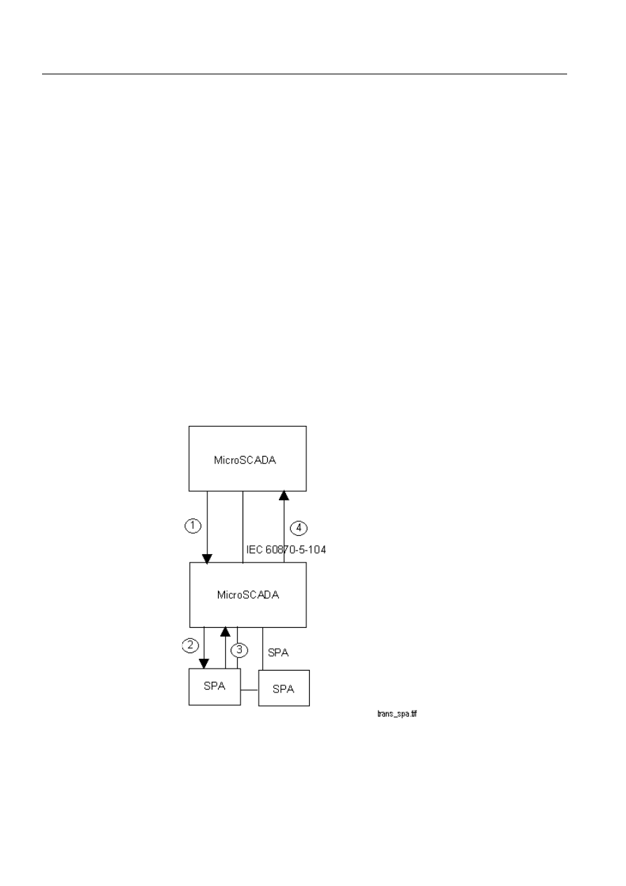
46
1MRS751964-MEN
Configuring MicroSCADA for IEC
60870-5-104 Master Protocol
COM 500
4. Technical description
Configuration Guide
to this process object is an event channel, which activates a
command procedure. The SPA message is parsed by the
command procedure as in the following:
@SPA_MSG = TYPE_CAST(%BS,"TEXT")
The SPA message is sent to the SPA unit and the corresponding
answer is read by using the SM attribute of the SPA station as in
the following:
#SET STA2:SSM = %SPA_MSG
@SPA_ANSW = STA2:SSM
Step
:
The answer is sent back to the IEC master as an activation
confirmation of the command, i.e. the encapsulated SPA reply
message, as in the following:
@IEC_STA_NR = ’LN’:PUN’IX’
@ORIG = ’LN’:POG’IX’
@CMD_ADDR = ’LN’:POA’IX’
@CMD_TYPE = ’LN’:PTY’IX’
#SET STA’IEC_STA_NR’:SCF = -
(256*%ORIG+7,%CMD_ADDR,%CMD_TYPE,%SPA_ASW)
The message is received by the IEC master in a bit stream process objects with the
UN attribute equal to the STA object number of the IEC slave station and the OA
attribute value equal to the address of the command. In this case, the message can
also be interpreted by using the TYPE_CAST function to convert the message into
text.
)LJ
)ORZRIWKHWUDQVSDUHQW63$PHVVDJHV
By using a mechanism like the one described above, it is possible to read and write
the parameters of SPA units over an IEC 60870-5-104 line. The same kind of
1MRS751964-MEN
COM 500
47
Configuring MicroSCADA for IEC
60870-5-104 Master Protocol
Configuration Guide
4. Technical description
4
mechanism can also be used for other purposes. For example, exchanging free-
format text messages between the master and the slave.
4.2.8.
Parameter in control direction
In the IEC 60870-5-104 protocol it is possible for the master to set and activate
parameters of information objects of the IEC slave. This kind of action is, for
example, setting the limits of a measured value. The following ASDUs presented in
Table 4.2.8-1 are provided by the protocol:
Table 4.2.8-1
ASDUs for parameters in the control direction
All of these ASDUs can be sent by using the CO attribute of the IEC master station.
See the description of the CO attribute in Section 4.2.4 for more details.
ASDUs 110…112 are for setting the parameters of measured values. The syntax is
as in the following:
#SET STAn:SCO = (TYPE, ADDR,COT,VALUE,QUAL)
The elements of the argument vector set to the CO attribute are shown in Table
4.2.8-2.
Table 4.2.8-2
Arguments used when sending parameters of the measured
value ASDUs
When sending a parameter activation message (ASDU 113), the syntax of the CO
attribute is in the following. Table 4.2.8-3 describes the values of the elements in the
argument vector.
#SET STAn:SCO = (TYPE, ADDR,COT,QUAL)
Type id
ASDU
Description
110
P_ME_NA_1
Parameter of measured values, normalised value.
111
P_ME_NB_1
Parameter of measured values, scaled value.
112
P_ME_NC_1
Parameter of measured values, short floating point
number.
113
P_AC_NA_1
Parameter activation.
Argument
Description
TYPE
Type identification of the ASDU, integer 110…112.
ADDR
Information object address of the target measured value objec.t
COT
Cause of transmission, integer 6.
VALUE
Value of the parameter as normalised value (ASDU 110), scaled value
(ASDU 111) or short floating point number (ASDU 113).
QUAL
Qualifier of the ASDU as follows: 1 = threshold value, 2 = smoothing
factor, 3 = low limit, 4 = high limit.

48
1MRS751964-MEN
Configuring MicroSCADA for IEC
60870-5-104 Master Protocol
COM 500
4. Technical description
Configuration Guide
Table 4.2.8-3
The arguments used when sending the parameter activation
ASDUs
([DPSOHV
;send the low limit 100 of the object with address 1500 as scaled value
#SET STA1:SCO = (111,1500,6,100,3)
;deactivate the previous parameter setting
#SET STA1:SCO = (113,1500,8,2)
4.3.
Signal engineering
The term signal engineering means the engineering needed for establishing the
communication to the IEC slave station. Signal engineering is made after the system
configuration is completed and the process database needed for the process
communication is ready. We recommend using the LIB 5xx application libraries for
creating the process database.
The following steps are taken when making signal engineering for an IEC:
Make a list of all the signals that are to be transferred between the master and
the slave. For each signal, include the type identification of the ASDU, the link
address and the common address of ASDU, and information about whether the
signal is to be sent with or without time tag.
Determine the length of the IEC addresses (link address, common address of
ASDU and information object address) and the cause of transmission.
Select the communication mode (balanced or unbalanced) to be used based on
the implementation of the slave and the network topology.
Test each signal.
4.4.
Status codes
The following status codes are defined for the IEC 60870-5-104 master protocol.
Some typical reasons for some of the status codes are also given.
Status codes are sent as system messages, which can be received by analog input
project objects with a unit number (UN) 0 and object address (OA) as determined by
the MI attribute of the line or station.
Argument
Description
TYPE
Type identification of the ASDU, integer 113
ADDR
Information object address of the target object
COT
Cause of transmission, integer 6 = activate, 8 = deactivate
QUAL
Qualifier of the ASDU as follows: 1 = act/deact of the previously
loaded parameters (addr 0), 2 = act/deact of the parameter of the
addressed object, 3 = act/deact of persistent cyclic or periodic
transmission of the addressed object

1MRS751964-MEN
COM 500
49
Configuring MicroSCADA for IEC
60870-5-104 Master Protocol
Configuration Guide
4. Technical description
4
Line object status codes
17800
ITCP_REMOTE_HOST_CONTINUOUSLY_BUSY
Not used at the moment.
17801
ITCP_LINE_INITIALIZING
Line status value before the initialisation of the TCP interface for the
protocol is completed.
17802
ITCP_LINE_INITIALIZATION_FAILED
Line status value when the initialisation of the TCP interface failed.
17803
ITCP_REMOTE_HOST_BUSY
Device status is set to this value when the data transfer is disabled due
to received ‘stopdt’ frame.
17804
ITCP_REMOTE_HOST_NOT_RESPONDING
Device status is set to this value when the connection to a remote host
is not established.
17805
ITCP_LINE_NOT_CONNECTED
Line status is set to this value when there is no connection to any
configured host.
17806
ITCP_LINE_STOPPED
Line status value when the line is taken out of use.
17807
ITCP_RECEIVER_OUT_OF_BUFFERS
Internal error situation.
17808
ITCP_REMOTE_HOST_NOT_READY
Returned to SCIL in case there is no connection to the host.
17820
ITPC_ILLEGAL_ATTRIBUTE_VALUE
Returned to SCIL when the attribute value given is out of range.
Station object status codes
13851
ICCC_INVALID_ATTRIBUTE_VALUE
The value set to an attribute of an IEC station is incorrect, e.g. one of
the elements of the vector written to the SD attribute is out of range.
13852
ICCC_INVALID_INDEX_RANGE
The index range used when accessing an attribute of an IEC station is
incorrect.

50
1MRS751964-MEN
Configuring MicroSCADA for IEC
60870-5-104 Master Protocol
COM 500
4. Technical description
Configuration Guide
13853
ICCC_INVALID_ATTRIBUTE
The STA object attribute used is not valid for the IEC 60870-5-104
master protocol.
13854
ICCC_ASDU_TABLE_NOT_CREATED
Internal software error.
13855
ICCC_UNKNOWN_ASDU_NAME
The name of the ASDU written to a STA object attribute is not
supported.
13857
ICCC_MESSAGE_BUFFER_FULL
Internal software error. The value of the ML attribute may be too small.
13858
ICCC_MESSAGE_FILLING_ERROR
Internal software error. The value of the ML attribute may be too small.
13859
ICCC_UNKNOWN_ASDU
The number of the ASDU written to a STA object attribute is not
supported.
13862
ICCC_SC_DATA_OVERFLOW
Internal software error.
13863
ICCC_DEVICE_SUSPENDED
The IEC station is in suspended state. The reason for this could be that
the link is not properly established (e.g. incorrect cable wiring) or the
slave station does not respond.
13864
ICCC_MESSAGE_SENDING_ERROR
Internal software error. This may be the result of a problem in wiring
or hardware.
13865
ICCC_REMOTE_DEVICE_REPLIES_WITH_NACK
The slave did not accept the message but responded with a negative
acknowledgement instead. Not used in the unbalanced mode.
13866
ICCC_LINK_NOT_READY
A message is sent to a line with a non-established communication.
13868
ICCC_OUT_OF_BUFFERS
Internal software error. Operation could not be completed since the
buffer pool has ran out of buffers.
13870
ICCC_CONFIRMATION_TIMEOUT
An activation confirmation to a command was not received from the
IEC slave in the time defined by the RT attribute.
13871
ICCC_NEGATIVE_CONFIRMATION
The activation confirmation received from the IEC slave was negative,
i.e. the command failed.
13872
ICCC_DEVICE_STOPPED
The station has been set out of use by using the IU attribute.
13873
ICCC_NO_ADDRESS_IN_ACP
Internal software error.
13875
ICCC_UNEXPECTED_TYPE_IN_ACP
Internal software error.

1MRS751964-MEN
COM 500
51
Configuring MicroSCADA for IEC
60870-5-104 Master Protocol
Configuration Guide
4. Technical description
4
13876
ICCC_UNSUPPORTED_COMMAND_TYPE
The value of the TY attribute written to an output process object is not
a type id of a supported ASDU.
13877
ICCC_OV_VALUE_NOT_FOUND
The OV attribute is missing from the list written to an output process
object.
13879
ICCC_QL_VALUE_NOT_FOUND
The QL attribute is missing from the list written to an output process
object.
13880
ICCC_TY_VALUE_NOT_FOUND
The TY attribute is missing from the list written to an output process
object.
13881
ICCC_DEVICE_STARTED
The station has been set out of use by using the IU attribute.

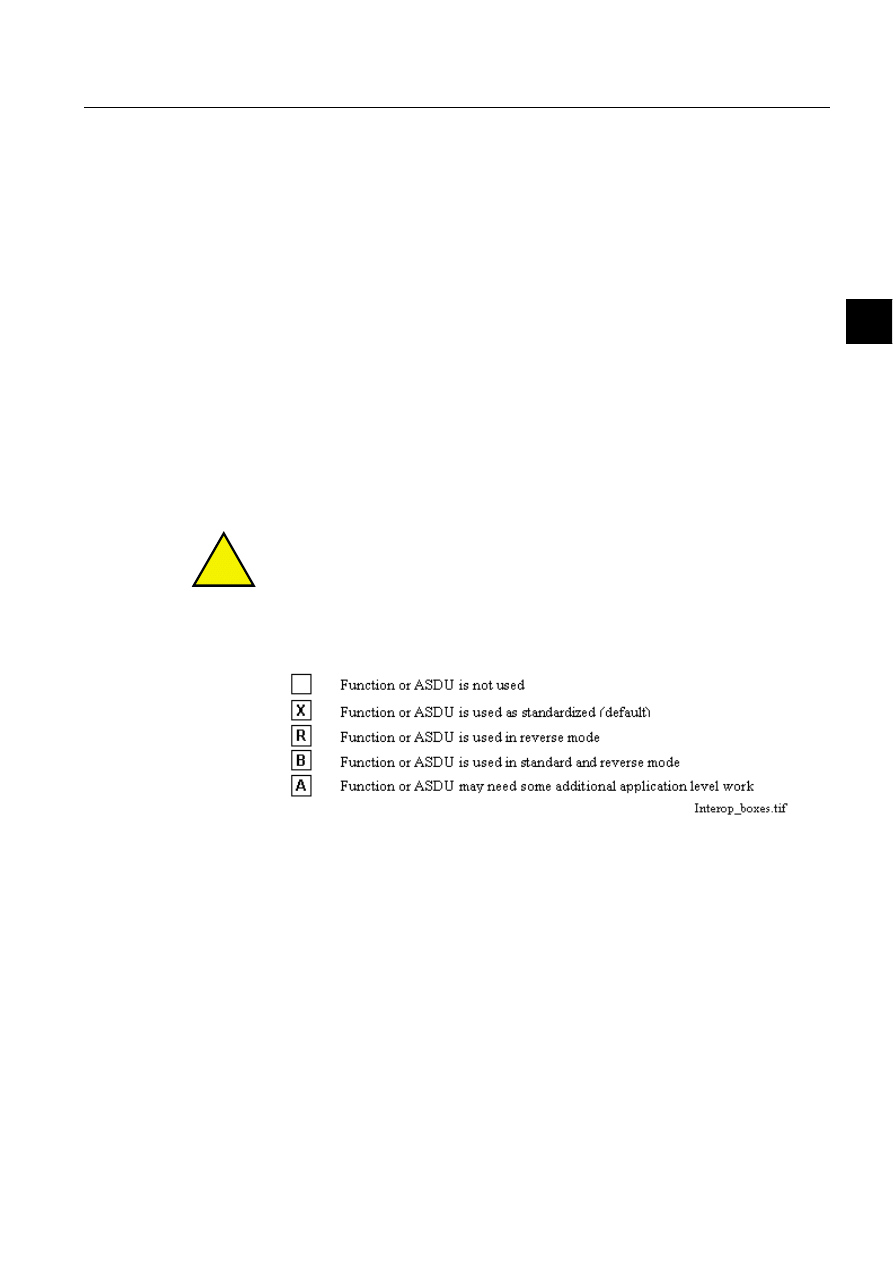
1MRS751964-MEN
COM 500
53
Configuring MicroSCADA for IEC
60870-5-104 Master Protocol
Configuration Guide
5. Appendix
5
5. Appendix
5.1.
Interoperability list for the 60870-5-104 master protocol
This companion standard presents sets of parameters and alternatives from which
subsets must be selected to implement particular telecontrol systems. Certain
parameter values, such as the choice of “structured“ or “unstructured“ fields of the
Information Object Address (IOA) of ASDUs represent mutually exclusive
alternatives. This means that only one value of the defined parameters is admitted
per system. Other parameters, such as the listed set of different process information
types in command and in monitor direction allow the specification of the complete
set or subsets, as appropriate for the applications. This clause summarises the
parameters of the previous clauses to facilitate a suitable selection for a specific
application. If a system is composed of equipment stemming from different
manufacturers it is necessary that all partners agree on the selected parameters.
The interoperability list is defined as in the IEC 60870-5-101 protocol and extended
with parameters used in this standard. The text descriptions of parameters which are
not applicable to this companion standard are struck out (the corresponding check
box is marked black).
!
The full specification of a system may require individual selection of certain
parameters for certain parts of the system, e.g. individual selection of scaling factors
for individually addressable measured values.
Application layer telegram formats
The possible selection (blank, X, R or B) is specified for each specific clause or
parameter. A black check box indicates that the option cannot be selected in this
companion standard.
1MRS751964-MEN
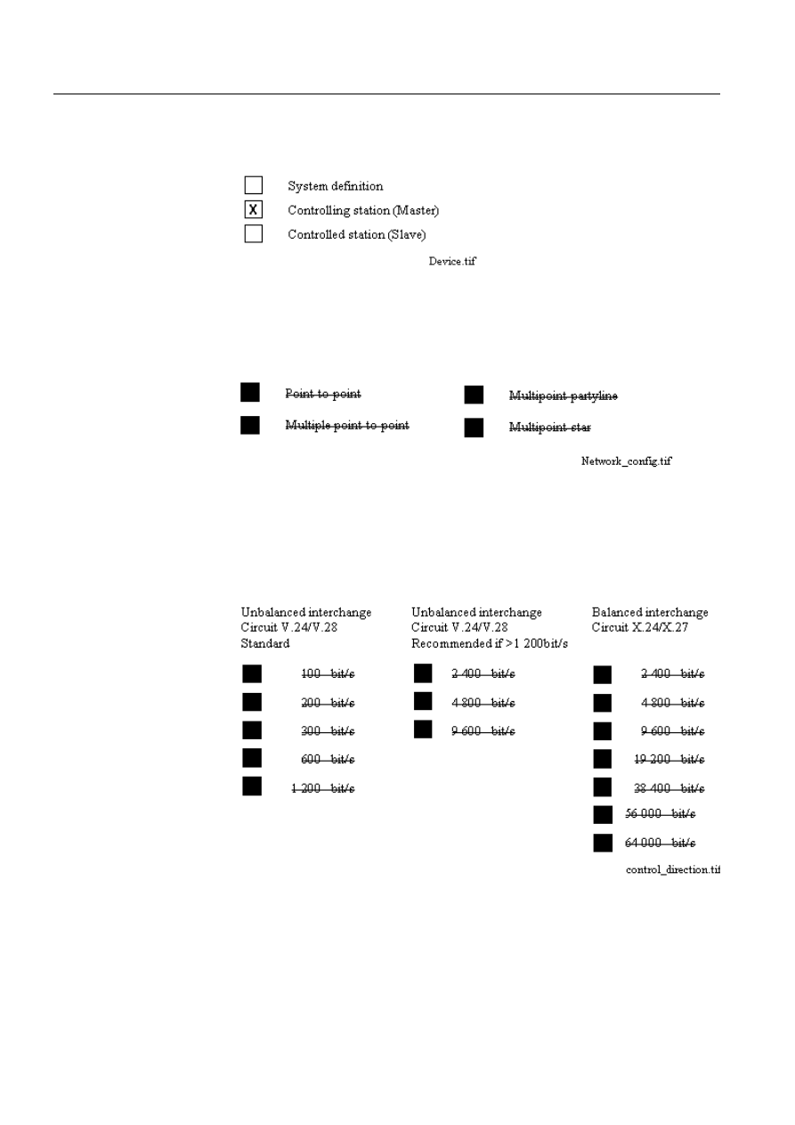
54
1MRS751964-MEN
Configuring MicroSCADA for IEC
60870-5-104 Master Protocol
COM 500
5. Appendix
Configuration Guide
Device function
(system specific parameter)
Network configuration
(network-specific parameter)
Physical layer
(network-specific parameter)
7UDQVPLVVLRQVSHHGFRQWUROGLUHFWLRQ
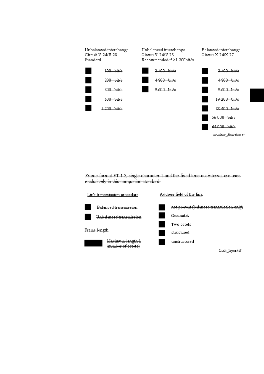
1MRS751964-MEN
COM 500
55
Configuring MicroSCADA for IEC
60870-5-104 Master Protocol
Configuration Guide
5. Appendix
5
7UDQVPLVVLRQVSHHGPRQLWRUGLUHFWLRQ
Link layer
(network-specific parameter)
When using an unbalanced link layer, the following ASDU types are returned in
class 2 messages (low priority) with the indicated causes of transmission:
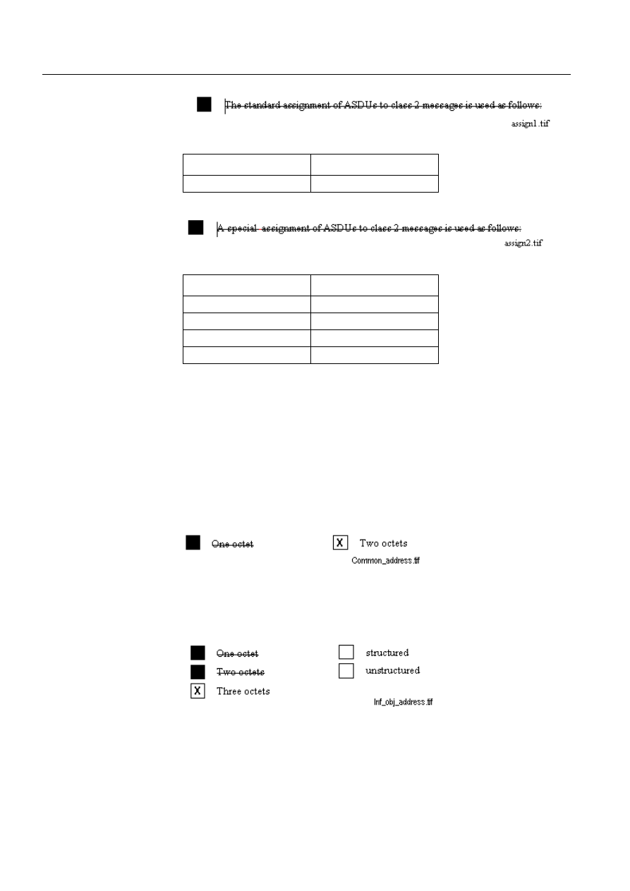
56
1MRS751964-MEN
Configuring MicroSCADA for IEC
60870-5-104 Master Protocol
COM 500
5. Appendix
Configuration Guide
Application layer
7UDQVPLVVLRQPRGHIRUDSSOLFDWLRQGDWD
Mode 1 (the least significant octet first), as defined in clause 4.10 of IEC 60870-5-
4, is used exclusively in this companion standard.
&RPPRQDGGUHVVRI$6'8
(system-specific parameter)
,QIRUPDWLRQREMHFWDGGUHVV
(system-specific parameter)
Type identification
Cause of transmission
9, 11, 13, 21
<1>
Type identification
Cause of transmission

1MRS751964-MEN
COM 500
57
Configuring MicroSCADA for IEC
60870-5-104 Master Protocol
Configuration Guide
5. Appendix
5
&DXVHRIWUDQVPLVVLRQ
(system-specific parameter)
/HQJWKRI$3'8
(system-specific parameter)
The maximum length of the APDU is 253 (default). The maximum length may be
reduced per system.
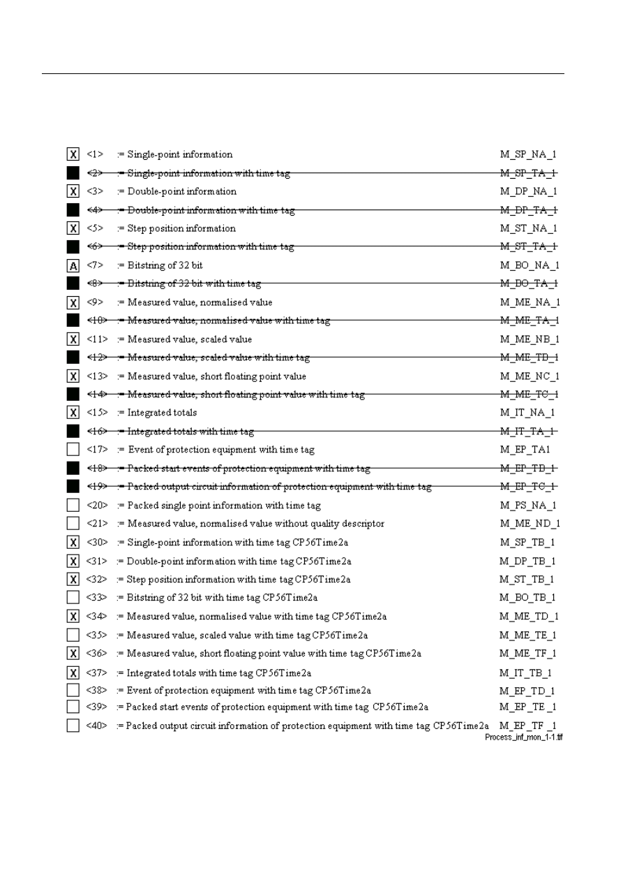
58
1MRS751964-MEN
Configuring MicroSCADA for IEC
60870-5-104 Master Protocol
COM 500
5. Appendix
Configuration Guide
6HOHFWLRQRIVWDQGDUG$6'8V
3URFHVVLQIRUPDWLRQLQPRQLWRUGLUHFWLRQ
(station-specific parameter)
Either the ASDUs of the set <2>, <4>, <6>, <8>, <10>, <12>, <14>, <16>, <17>,
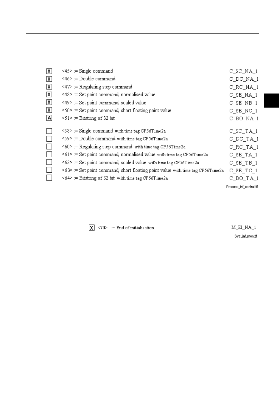
1MRS751964-MEN
COM 500
59
Configuring MicroSCADA for IEC
60870-5-104 Master Protocol
Configuration Guide
5. Appendix
5
<18>, <19> or of the set <30> - <40> are used.
3URFHVVLQIRUPDWLRQLQFRQWUROGLUHFWLRQ
(station-specific parameter)
Either the ASDUs of the set <45> - <51> or of the set <58> - <64> are used.
6\VWHPLQIRUPDWLRQLQPRQLWRUGLUHFWLRQ
(station-specific parameter)
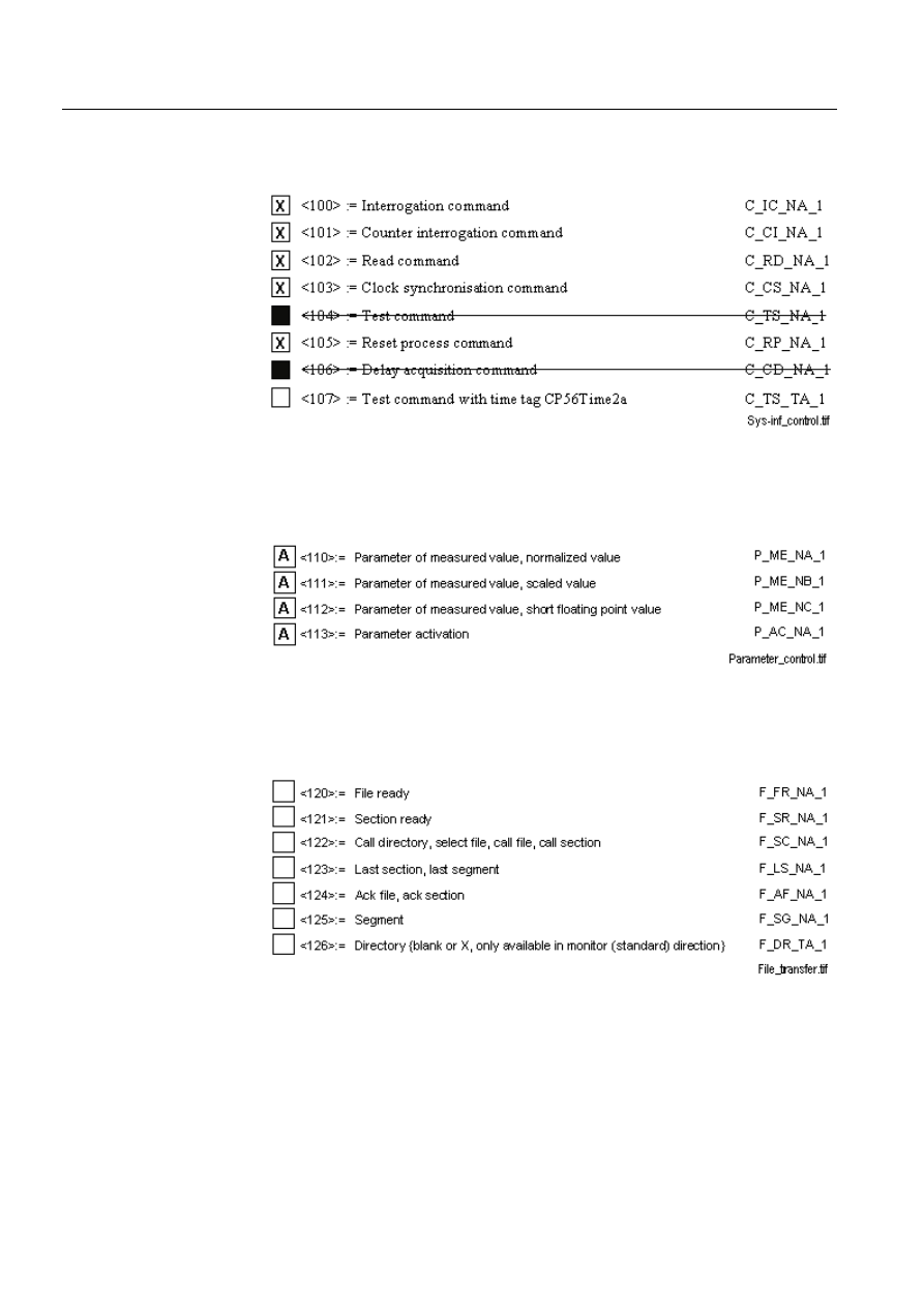
60
1MRS751964-MEN
Configuring MicroSCADA for IEC
60870-5-104 Master Protocol
COM 500
5. Appendix
Configuration Guide
6\VWHPLQIRUPDWLRQLQFRQWUROGLUHFWLRQ
(station-specific parameter)
3DUDPHWHULQFRQWUROGLUHFWLRQ
(station-specific parameter)
)LOHWUDQVIHU
(station-specific parameter)
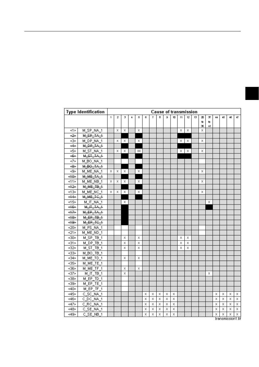
1MRS751964-MEN
COM 500
61
Configuring MicroSCADA for IEC
60870-5-104 Master Protocol
Configuration Guide
5. Appendix
5
7\SHLGHQWLILHUDQGFDXVHRIWUDQVPLVVLRQDVVLJQPHQWV
(station-specific parameters)
- Shaded boxes are not required
- Black boxes are not permitted in this companion standard
- Blank = Function or ASDU is not used
- Mark Type identification/Cause of transmission combinations:
‘
;’ if supported only in the standard direction
‘
5’ if supported only in the reverse direction
‘
%’ if supported in both directions
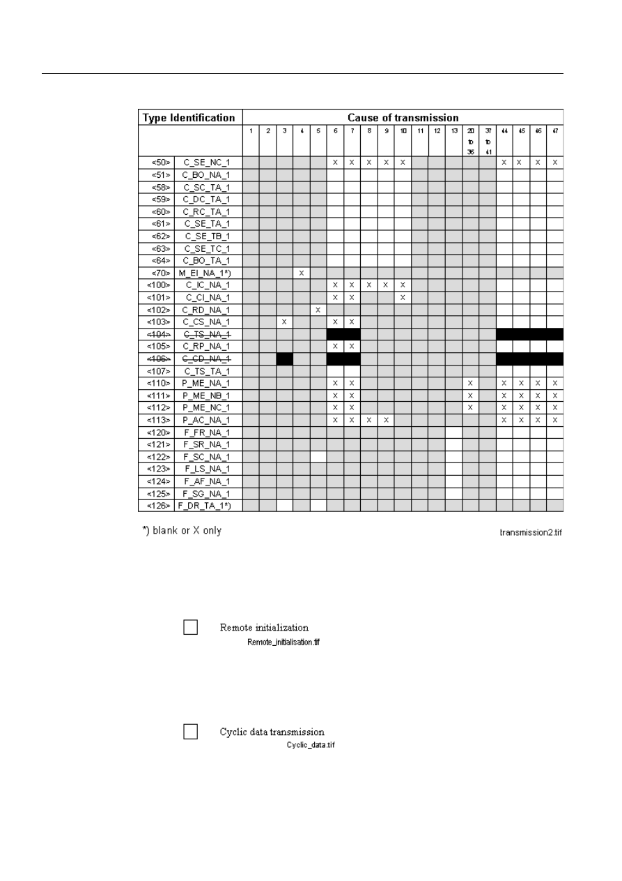
62
1MRS751964-MEN
Configuring MicroSCADA for IEC
60870-5-104 Master Protocol
COM 500
5. Appendix
Configuration Guide
Basic application functions
6WDWLRQLQLWLDOLVDWLRQ
(station-specific parameter)
&\FOLFGDWDWUDQVPLVVLRQ
(station-specific parameter)
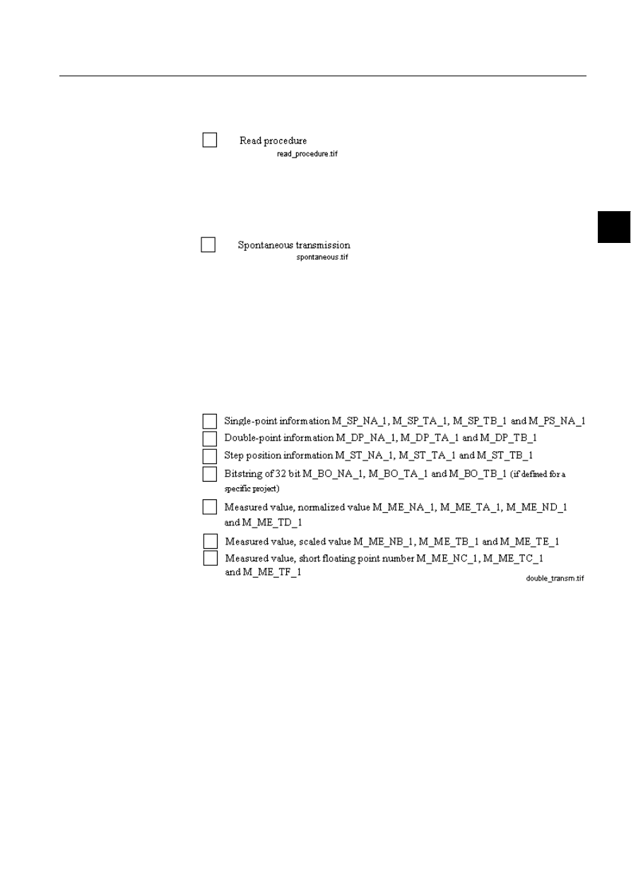
1MRS751964-MEN
COM 500
63
Configuring MicroSCADA for IEC
60870-5-104 Master Protocol
Configuration Guide
5. Appendix
5
5HDGSURFHGXUH
(station-specific parameter)
6SRQWDQHRXVWUDQVPLVVLRQ
(station-specific parameter)
'RXEOHWUDQVPLVVLRQRILQIRUPDWLRQREMHFWVZLWKFDXVHRIWUDQVPLVVLRQ
VSRQWDQHRXV
(station-specific parameter)
The following type identifications may be transmitted in succession caused by a
single status change of an information object. The particular information object
addresses for which double transmission is enabled are defined in a project-specific
list.
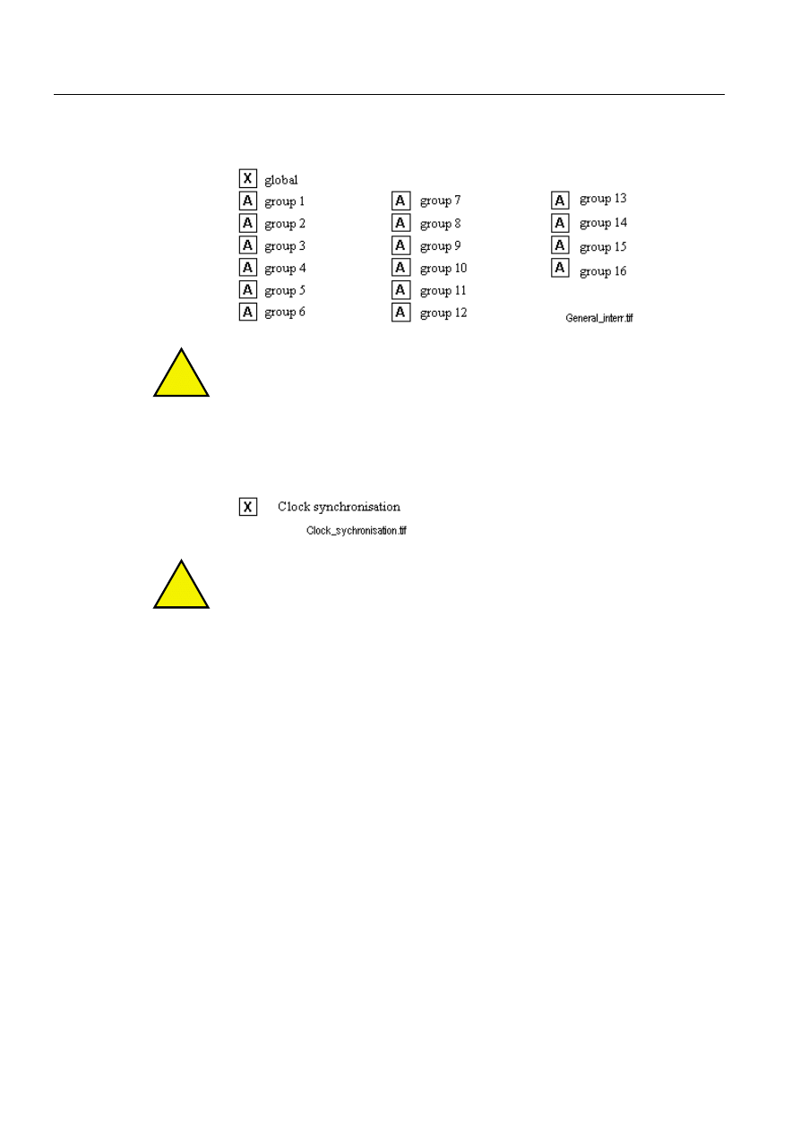
64
1MRS751964-MEN
Configuring MicroSCADA for IEC
60870-5-104 Master Protocol
COM 500
5. Appendix
Configuration Guide
6WDWLRQLQWHUURJDWLRQ
(system parameter or station-specific parameter)
!
Information Object Addresses assigned to each group have to be defined.
&ORFNV\QFKURQLVDWLRQ
(station-specific parameter)
!
Optional, see clause 7.6 of the companion standard IEC 60870-5-104.
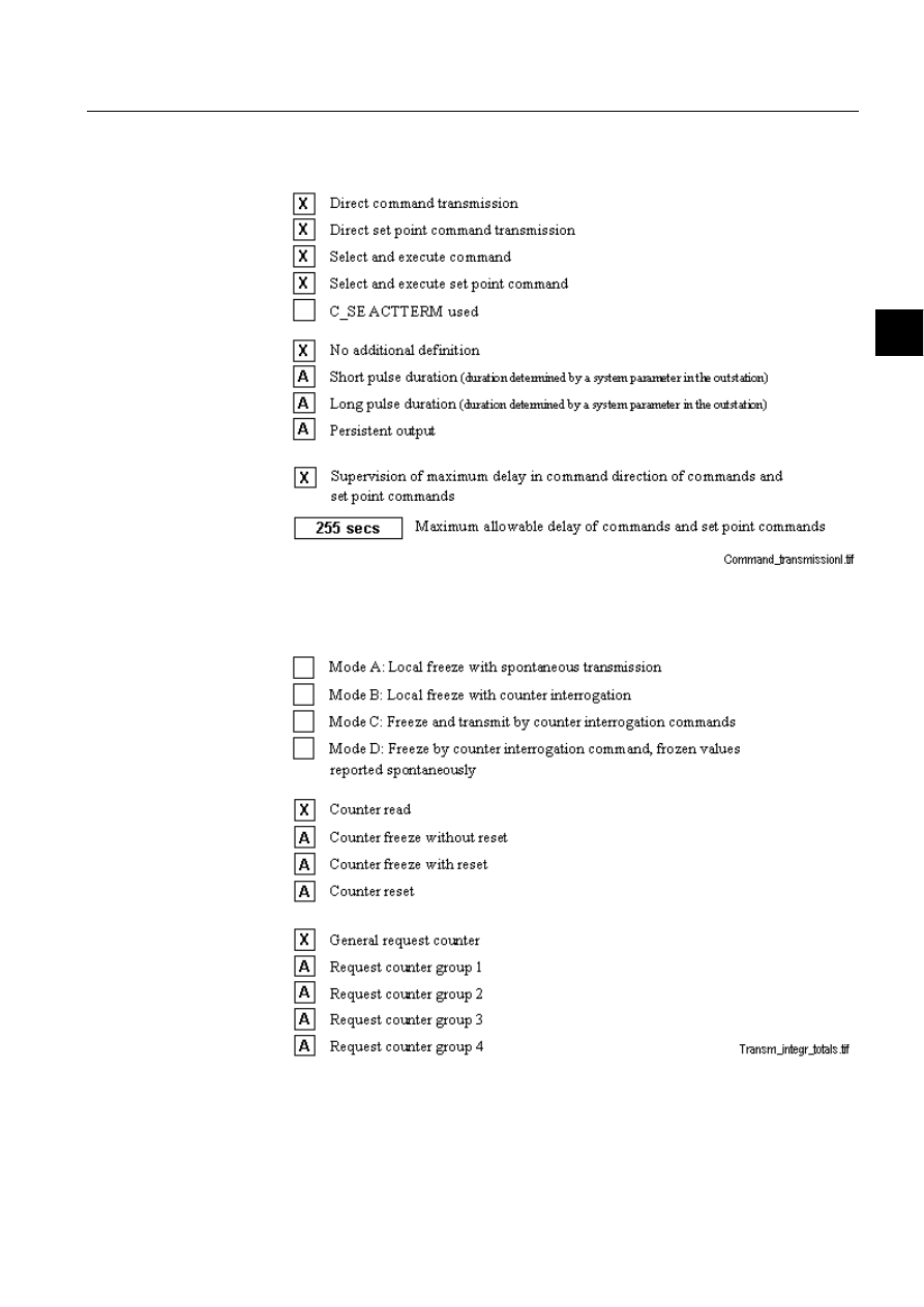
1MRS751964-MEN
COM 500
65
Configuring MicroSCADA for IEC
60870-5-104 Master Protocol
Configuration Guide
5. Appendix
5
&RPPDQGWUDQVPLVVLRQ
(object-specific parameter)
7UDQVPLVVLRQRILQWHJUDWHGWRWDOV
(station parameter or object-specific parameter)
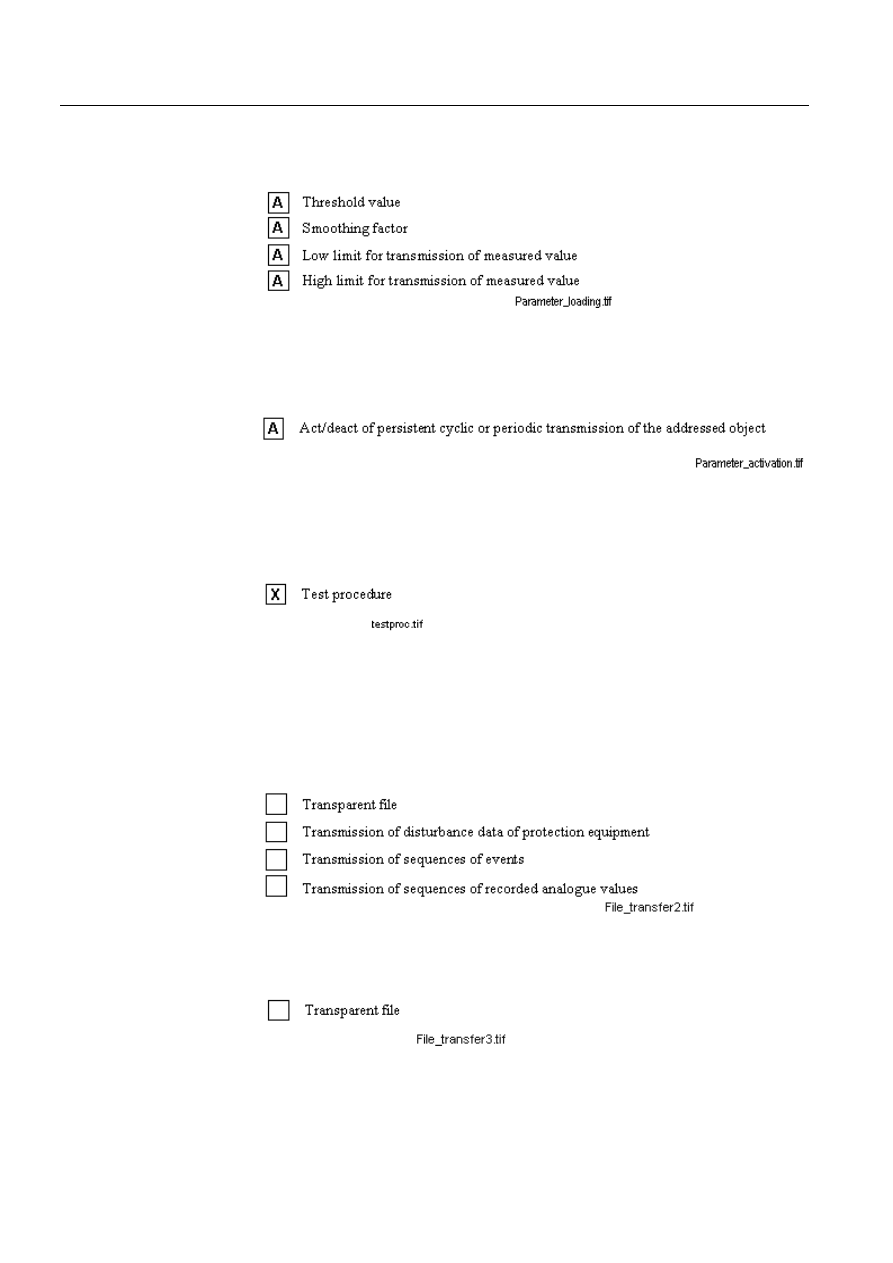
66
1MRS751964-MEN
Configuring MicroSCADA for IEC
60870-5-104 Master Protocol
COM 500
5. Appendix
Configuration Guide
3DUDPHWHUORDGLQJ
(object-specific parameter)
3DUDPHWHUDFWLYDWLRQ
(object-specific parameter)
7HVWSURFHGXUH
(object-specific parameter)
)LOHWUDQVIHU
(station-specific parameter)
File transfer in monitor direction
File transfer in control direction
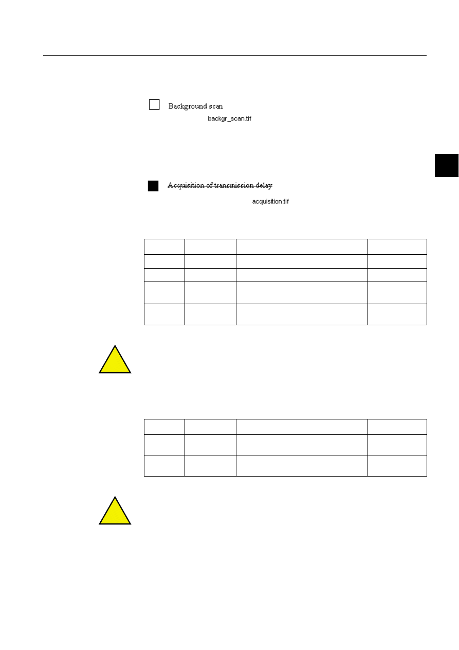
1MRS751964-MEN
COM 500
67
Configuring MicroSCADA for IEC
60870-5-104 Master Protocol
Configuration Guide
5. Appendix
5
%DFNJURXQGVFDQ
(station-specific parameter)
$FTXLVLWLRQRIWUDQVPLVVLRQGHOD\
(station-specific parameter)
'HILQLWLRQRIWLPHRXWV
!
Maximum range of values for all the time-outs: 1 to 255 seconds, accuracy 1 s.
0D[LPXPQXPEHURIRXWVWDQGLQJ,IRUPDW$3'8VNDQGWKHODWHVW
DFNQRZOHGJHPHQWZ
!
Maximum range of values k: 1 to 32767 (2
15
-1) APDUs, accuracy 1 APDU.
Maximum range of values w: 1 to 32767 APDUs, accuracy 1 APDU
(Recommendation: w should not exceed 2/3 of k).
Parameter
Default value
Remarks
Selected value
t
0
30 s
Time-out of connection establishment
1-255 s
t
1
15 s
Time-out of send or test APDUs
1-255 s
t
2
10 s
Time-out for acknowledges in case of no
data messages t
2
< t
1
1-255 s
t
3
20 s
Time-out for sending test frames in case
of a long idle state
1-255 s
Parameter
Default value
Remarks
Selected value
k
12 APDUs
Maximum difference receive sequence
number to send state variable
1-32767 s
w
8 APDUs
Latest acknowledgement after receiving w
I-format APDUs
1-32767 s
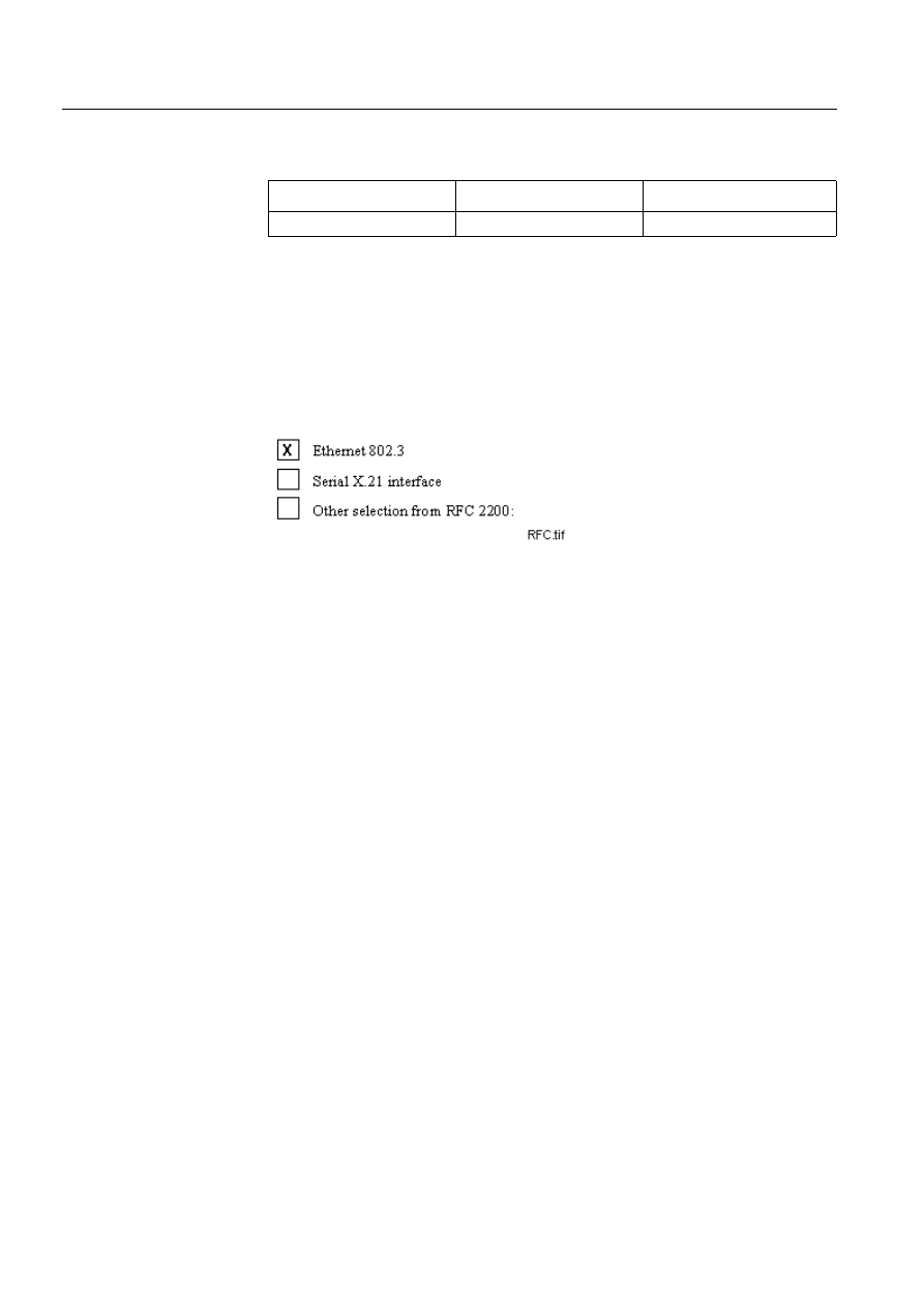
68
1MRS751964-MEN
Configuring MicroSCADA for IEC
60870-5-104 Master Protocol
COM 500
5. Appendix
Configuration Guide
3RUWQXPEHU
5)&VXLWH
RFC 2200 is an official Internet Standard, which describes the state of
standardisation of protocols used in the Internet as determined by the Internet
Architecture Board (IAB). It offers a broad spectrum of actual standards used in the
Internet. The suitable selection of documents from RFC 2200 defined in this
standard for given projects has to be chosen by the user of this standard.
List of valid documents from RFC 2200
Parameter
Default value
Remarks
Portnumber
2404
In all cases
1. ...........................................................
2. ...........................................................
3. ...........................................................
4. ...........................................................
5. ...........................................................
6. ...........................................................
7. etc.

1MRS751964-MEN
COM 500
69
Configuring MicroSCADA for IEC
60870-5-104 Master Protocol
Configuration Guide
5. Appendix
5
5.2.
Description of the SPA bus messages
In distribution automation systems the SPA-bus protocol may be required to access
device information that is not mapped to the IEC 60870-5-104 protocol. This
information includes several device specific parameters and recorded disturbance
data. Two ASDU types from the private range have been selected to enable
transparent transfer of the SPA-bus messages.
$6'863$EXVPHVVDJH
TYPE IDENT 133: C_SB_NA_1
SPA-bus message
Single information object (SQ = 1)
Table 5.2.-1 ASDU C_SB_NA_1 – SPA-bus message
* N defines, in binary format, the number of information elements (characters) in the
ASDU. N is a value between 0 and 127.
CAUSES OF TRANSMISSION used with TYPE IDENT 133: = C_SB_NA_1
CAUSE OF TRANSMISSION
• In control direction:
<6>:=activation.
• In monitor direction:
<7>:=activation confirmation
1
0
0
0
0
1
0
1
TYPE
IDENTIFICATION
1
N*
VARIABLE
STRUCTURE
QUALIFIER
DATA UNIT
CAUSE OF
TRANSMISSION
IDENTIFIER
COMMON
ADDRESS OF ASDU
INFORMATION
OBJECT ADDRESS
INFORMATION
OBJECT
SPA-bus command
message
(in control direction)
or
SPA-bus reply
message
(in monitor direction)

70
1MRS751964-MEN
Configuring MicroSCADA for IEC
60870-5-104 Master Protocol
COM 500
5. Appendix
Configuration Guide
$6'863$EXVUHSO\PHVVDJH
TYPE IDENT 130: M_SB_NA_1
SPA-bus reply message
Single information object (SQ = 0)
Table 5.2.-2 ASDU M_SB_NA_1 – SPA-bus Reply Message
CAUSES OF TRANSMISSION used with TYPE IDENT 130: = M_SB_NA_1
CAUSE OF TRANSMISSION
• In monitor direction:
<5>:= requested
7UDQVIHUSURFHGXUH
Transparent transfer of the SPA-bus messages can be initiated by the controlling
station by sending a SPA command message to the controlled station using
C_SB_NA_1 ASDU with a cause of transmission 'activation'. The controlled station
returns a corresponding SPA reply message using C_SB_NA_1 ASDU with a cause
of transmission 'activation confirmation'
The last SPA reply message can also be requested by the controlling station using
the Read application function. The controlled station returns the latest SPA reply
message using M_SB_NA_1 ASDU with a cause of transmission 'requested'. The
transfer procedure is presented in Figure 5.2.-1.
1
0
0
0
0
0
1
0
TYPE IDENTIFICATION
0
0
0
0
0
0
0
1
VARIABLE
STRUCTURE
QUALIFIER
DATA UNIT
CAUSE OF
TRANSMISSION
IDENTIFIER
COMMON ADDRESS
OF ASDU
INFORMATION
OBJECT ADDRESS
INFORMATION
OBJECT
SPA-bus reply message
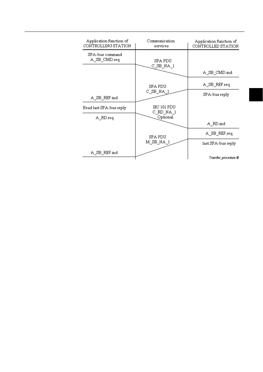
1MRS751964-MEN
COM 500
71
Configuring MicroSCADA for IEC
60870-5-104 Master Protocol
Configuration Guide
5. Appendix
5
)LJ 7KHWUDQVIHUSURFHGXUHRIWUDQVSDUHQW63$EXVSURWRFRO
5.3.
Description of parameter/byte string messages
In distribution automation systems several outstation parameters may be accessed as
unstructured byte strings (e.g. configuration data, device description texts, modem
control strings). Two ASDU types from the private range have been selected to
enable the parameter setting and parameter reading operations.

72
1MRS751964-MEN
Configuring MicroSCADA for IEC
60870-5-104 Master Protocol
COM 500
5. Appendix
Configuration Guide
$6'8±3DUDPHWHUE\WHVWULQJ
TYPE IDENT 131: C_SR_NA_1
Parameter, byte string
Single information object (SQ = 0)
Table 5.3.-1 ASDU C_SR_NA_1 – Parameter, byte string
CAUSES OF TRANSMISSION used with TYPE IDENT 131: = C_SR_NA_1
CAUSE OF TRANSMISSION
• In control direction:
<6>:=activation
• In monitor direction:
<7>:=activation confirmation
1
0
0
0
0
0
1
1
TYPE IDENTIFICATION
0
0
0
0
0
0
0
1
VARIABLE
STRUCTURE
QUALIFIER
DATA UNIT
CAUSE OF
TRANSMISSION
IDENTIFIER
COMMON ADDRESS
OF ASDU
INFORMATION
OBJECT ADDRESS
INFORMATION
OBJECT
Character string or byte
array

1MRS751964-MEN
COM 500
73
Configuring MicroSCADA for IEC
60870-5-104 Master Protocol
Configuration Guide
5. Appendix
5
$6'8±3DUDPHWHUGDWDE\WHVWULQJ
TYPE IDENT 128: M_SR_NA_1
Parameter, byte string
Single information object (SQ = 0)
Table 5.3.-2 ASDU M_SR_NA_1 – Parameter data, byte string
CAUSES OF TRANSMISSION used with TYPE IDENT 128: = M_SR_NA_1
CAUSE OF TRANSMISSION
• In control direction:
<6>:=activation
• In monitor direction:
<7>:=activation confirmation
3DUDPHWHUVHWWLQJDQGUHDGLQJSURFHGXUH
String parameter setting can be initiated by the controlling station by sending a
parameter value to the controlled station using C_SR_NA_1 ASDU with a cause of
transmission 'activation'. The controlled station returns an acknowledgement using
C_SB_NA_1 ASDU with a cause of transmission 'activation confirmation'.
The string parameter value can also be requested by the controlling station using the
Read (ASDU 102, C_RD_NA_1) application function. The controlled station
returns the addressed parameter value using M_SR_NA_1 ASDU with a cause of
transmission 'requested'.
1
0
0
0
0
0
1
1
TYPE IDENTIFICATION
0
0
0
0
0
0
0
1
VARIABLE
STRUCTURE
QUALIFIER
DATA UNIT
CAUSE OF
TRANSMISSION
IDENTIFIER
COMMON ADDRESS
OF ASDU
INFORMATION
OBJECT ADDRESS
INFORMATION
OBJECT
Character string or byte
array
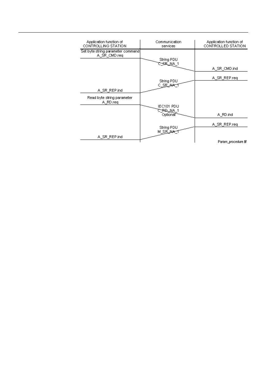
74
1MRS751964-MEN
Configuring MicroSCADA for IEC
60870-5-104 Master Protocol
COM 500
5. Appendix
Configuration Guide
)LJ 7KHSDUDPHWHUVHWWLQJDQGUHDGLQJSURFHGXUH

COM500
Index
Configuration Guide
Index
Page
$
Activation Reply Timeout
............................................................................................. 26
Activation Termination Timeout
................................................................................... 26
Addressing
AL
Allocating Application
Allocation
Analog
,QSXWV
6HWSRLQWV
APDUs
Application commands
..................................................................................... 35
Application Service Data Units (ASDUs)
........................................................ 27
AS
AT
%
Balanced mode
Binary inputs
Bit streams
BL
Buffer Pool Size
&
CA
Cause of transmission (COT)
.....................................................................14
Central stations
CF
CL
Clock synchronisation
................................................................................24
CO
Command Address
Command Out
Command transactions
Configuration
Counter interrogation
CT
CY
'
DC
Diagnostic Counters
................................................................................................20
Digital inputs
Double binary inputs
Double indications
(
End of initialisation
.................................................................................................24
ET
1MRS751964-MEN
Configuring MicroSCADA for IEC
60870-5-104 Master Protocol

1MRS751964-MEN
Configuring MicroSCADA for IEC
60870-5-104 Master Protocol
COM500
Index
Configuration Guide
)
Fatal error
*
General interrogation
.............................................................................................. 34
GI
+
HT
,
IA
IEC 60870-5-101 master protocol
................................................................................... 9
IEC 60870-5-101 slave protocol
................................................................................... 13
IEC870-5-104
IL
In Use
Information Address Length
......................................................................................... 22
Integrated link
IOA
IP address
IU
IV
.
k
/
LAN
Length of Cause of Transmission Information
............................................................. 22
Level of implementation
............................................................................................... 31
LI
Line Number
Line Object Attributes
Line Object Status Codes
.............................................................................................. 49
0
Maximum Message Length
........................................................................................... 24
Message Application
............................................................................................... 19
Message Identification
............................................................................................ 19
MI
ML
MS
Multidrop network topology
......................................................................................... 17
1
No limitations
NT
2
Object commands
Object Status

1MRS751964-MEN
COM500
Index
Configuring MicroSCADA for IEC
60870-5-104 Master Protocol
Configuration Guide
OF
OG
OR
OS
Outstations
OV
3
Parameter in control direction
.......................................................................... 32
PD
PO
Polling Delay
Private ASDUs
Process object types
.................................................................................................37
Protocol
Protocol converter
PS
Pulse counters
4
QL
5
Read command
Read, conditional write
Read-only
Remote host
Reset process command
................................................................................................ 45
Response Timeout
RM
RM attribute
RT
Running Mode
6
SA
SB
SD
SE
Signal address
Single indications
SL
Spontaneous data
ST
Station Address
Station Address Length
................................................................................................. 22
Station Object Attributes
............................................................................................... 21
Station Object Status Code
............................................................................................ 49
Status codes
$SSOLFDWLRQ/D\HU
/LQN/D\HU
Structured address
SU

1MRS751964-MEN
Configuring MicroSCADA for IEC
60870-5-104 Master Protocol
COM500
Index
Configuration Guide
Summer Time
SY
Synchronise
SYS Waiting Time
SYS_BASCON.COM
System
&RPPDQGV
0HVVDJHV
2EMHFWV
System commands
System Messages Enabled
............................................................................................ 23
7
t0
t1
t2
t3
TCP Connect
TD
TI
Timeout
Transparent Data
Transparent SPA
................................................................................................45
Transport layer
TY
8
U(TESTFR)
Unstructured address
UR
US
:
w
WAN
Write-only


Document Outline
- Introduction
- Safety information
- Instructions
- Technical description
- Appendix
Wyszukiwarka
Podobne podstrony:
Configuring MicroSCADA for IEC 60870 5 103 Master Protocol
Configuring MicroSCADA for IEC 60870 5 101 Master Protocol
Configuring MicroSCADA for IEC 60870 5 104 Slave Protocol
Configuring MicroSCADA for IEC 60870 5 101 Slave Protocol
Configuring MicroSCADA for DNP V3 00 Master Protocol
Configuring MicroSCADA for DNP V3 00 Slave Protocol
Configuring MicroSCADA for Modbus Master Protocol
Configuring MicroSCADA for Modbus Slave Protocol
Configuring MicroSCADA for OPC DA Client
23 299 318 Optimizing Microstructure for High Toughness Cold Work Steels
23 299 318 Optimizing Microstructure for High Toughness Cold Work Steels
End to end security implementation for mobile devices using TLS protocol
Confocal optics microscopy for biochemical and cellular high throughput screening by Lenka Zemanová,
37 509 524 Microstructure and Wear Resistance of HSS for Rolling Mill Rolls
Installing WSUS for Configuration Manager 2012 R2
steel?rgoes guidelines for master and co
Słownik, ACPI (Advanced Configuration and Power Interface): Standard zarządzania energią wypracowany
Słownik, ACPI (Advanced Configuration and Power Interface): Standard zarządzania energią wypracowany
więcej podobnych podstron