
1MRS751864-MEN
Issued:
15.03.2002
Version:
A
Program revision: 4.0
We reserve the right to change data without prior notice.
Configuring MicroSCADA for Modbus
Slave Protocol
Configuration Guide
COM 500
Notice 1
The information in this document is subject to change without notice and should not
be construed as a commitment by ABB. ABB assumes no responsibility for any error
that may occur in this document.
Notice 2
This document complies with the program revision 4.0.
Notice 3
Additional information such as Release Notes and Last Minute Remarks can be
found on the program distribution media.
Trademarks
Microsoft is a registered trademark of Microsoft Corporation.
Windows NT is a trademark of Microsoft Corporation.
L
ON
W
ORKS
is a registered trademark of Echelon Corporation.
Other brand or product names are trademarks or registered trademarks of their respective holders.
All Microsoft products referenced in this document are either trademarks or registered trademarks of Microsoft
Corporation.


MicroSCADA Technology Manuals
SYS 500 manuals
COM 500 manuals
Application Objects
1MRS751848-MEN
Introduction to MicroSCADA Technology
1MRS751852-MUM
JAVA-API for MicroSCADA
1MRS751851-MEN
Programming Language SCIL
1MRS751849-MEN
SCIL-API for MicroSCADA
1MRS752199-MEN
Status Codes
1MRS751850-MEN
System Configuration
1MRS751846-MEN
System Objects
1MRS751847-MEN
Configuring MicroSCADA for OPC DA Client
1MRS752246-MEN
Installation
1MRS751853-MEN
Picture Editing
1MRS751854-MEN
System Management
1MRS751857-MEN
Visual SCIL Objects
1MRS751856-MEN
Visual SCIL User Interface Design
1MRS751855-MEN
COM 500 Engineering
1MRS751858-MEN
Connecting LONWORKS Devices to MicroSCADA
1MRS751845-MEN
Communication Programming Interface (CPI)
1MRS751859-MEN
Configuring MicroSCADA for DNP V3.00 Master Protocol
1MRS751860-MEN
Configuring MicroSCADA for DNP V3.00 Slave Protocol
1MRS751861-MEN
Configuring MicroSCADA for IEC 60870-5-101 Master Protocol
1MRS751862-MEN
Configuring MicroSCADA for IEC 60870-5-101 Slave Protocol
1MRS751863-MEN
Configuring MicroSCADA for IEC 60870-5-103 Master Protocol
1MRS752012-MEN
Configuring MicroSCADA for IEC 60870-5-104 Master Protocol
1MRS751964-MEN
Configuring MicroSCADA for IEC 60870-5-104 Slave Protocol
1MRS751965-MEN
Configuring MicroSCADA for Modbus Master Protocol
1MRS752242-MEN
Configuring MicroSCADA for Modbus Slave Protocol
1MRS751864-MEN
COM 500
Configuring MicroSCADA for Modbus
Slave Protocol
Configuration Guide
1MRS751864-MEN

LIB 500 manuals
LIB 510 manuals
SMS 510 manuals
CAP 505 manuals
Common manual for LIB, CAP and SMS
LIB 500 Configuration Manual
1MRS751880-MEN
LIB 500 Operator’s Manual
1MRS751885-MUM
LIB 510 Configuration
1MRS751886-MEN
LIB 510 MV Process Configuration
1MRS751887-MEN
LIB 510 MV Process Operator’s Manual
1MRS751891-MUM
LIB 510 Operator’s Manual
1MRS751888-MUM
SMS 510 Installation and Commissioning
1MRS751897-MEN
SMS 510 Operator’s Manual
1MRS751898-MUM
CAP 505 Installation and Commissioning
1MRS751901-MEN
CAP 505 Operator’s Manual
1MRS751902-MUM
Relay Configuration Tool Tutorial
1MRS751903-MEN
Relay Mimic Editor Configuration
1MRS751904-MEN
Relay Configuration Tool Quick Start Reference
1MRS751905-MEN
SPTO Configuration Tool
1MRS751906-MEN
Protocol Editing Tool
1MRS751982-MUM
Tools for Relays and Terminals
1MRS752008-MUM
1MRS751864-MEN
Configuring MicroSCADA for Modbus
Slave Protocol
COM 500
Configuration Guide

1
2
3
4
1
2
3
4
COM 500
Configuring MicroSCADA for Modbus
Slave Protocol
Configuration Guide
1MRS751864-MEN


COM 500
Contents
Configuration Guide
Contents:
1MRS751864-MEN
Configuring MicroSCADA for Modbus
Slave Protocol
1. Introduction ...............................................................................1
2. Safety information .....................................................................3
3. Instructions ................................................................................5
3.2.1. Base system configuration .................................................5
3.2.2. Communication system configuration ................................8
3.3. After configuration .......................................................................11
3.4. Start-up .......................................................................................12
3.5. How to test the configuration .......................................................12
4. Technical description .............................................................15
4.2.1. CPI application program ..................................................15
4.2.2. Connection to a MicroSCADA base system ....................15
4.2.3. Data flow ..........................................................................16
4.2.4. Addressing schematics with Modbus protocol .................17
4.2.5. Device communication attributes .....................................18
4.3. Command procedures .................................................................21
4.3.1. Command procedures in COM 500 .................................21
4.3.2. Command procedures in SYS 500 ..................................22
4.3.2.1. Command procedures for process data .............22
4.3.2.2. Command procedures for commands ................24
4.4. Function codes ............................................................................26
4.4.1. Function codes for process data ......................................27
4.4.1.1. Function code 01 - Read coil status ...................27
4.4.1.2. Function code 02 - Read input status ................28
4.4.1.3. Function code 03 - Read holding registers ........28
4.4.1.4. Function code 04 - Read input registers ............29
4.4.2. Function codes for commands .........................................29
4.4.2.1. Function code 05 - Forcing a coil .......................29
4.4.2.2. Function code 06 - Modify register content ........30
4.4.2.3. Function code 08 - Diagnostics ..........................30
4.4.2.4. Function code 11 - Fetch communication event
counter ...............................................................32
4.5. Status codes ...............................................................................33

1MRS751864-MEN
COM 500
1
1. Introduction
Configuring MicroSCADA for Modbus
Slave Protocol
Configuration Guide
1
1. Introduction
Using this manual
This manual should be read when you want to use the Modbus slave protocol and
need information related to it. It describes how to configure the base system and the
Modbus slave application for communication between them and with the Modbus
master.
In addition to this configuration, the base system needs to be configured for the
process communication. For information about this subject, refer to other manuals,
for example the Application Objects manual or the COM 500 Engineering manual.
The Modbus master needs to be configured as well.
Referenced manuals
The following MicroSCADA manuals should be available for reference during the
use of this manual:
• System Configuration manual
• System Objects manual
• Application Objects manual
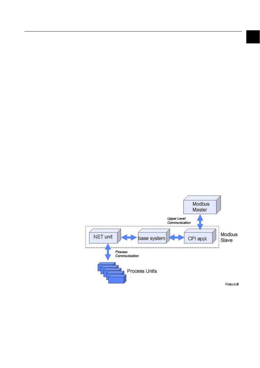
Modbus slave
The Modbus slave protocol is mainly used for upper level communication between
COM 500 or SYS 500 and a network control system as illustrated by Figure 1.-1. In
MicroSCADA the Modbus slave protocol is implemented by using the CPI protocol
development environment.
)LJ 7KH0RGEXVPDVWHUVHHVWKH1(7XQLWDQGWKHSURFHVVEHKLQGLWDVDVODYH
The data from the process activates a certain event channel and command procedure
in the base system. This command procedure sends the information forward to the
Modbus slave CPI application program and the Modbus master.
1MRS751864-MEN

2
1MRS751864-MEN
Configuring MicroSCADA for Modbus
Slave Protocol
COM 500
1.
Introduction
Configuration Guide
In COM 500 all protocol specific objects are created automatically (e.g. command
procedure, event channels). If SYS 500 is used, the user have to create an
application, which forwards the data between the process device and the Modbus
protocol.

1MRS751864-MEN
COM 500
3
Configuring MicroSCADA for Modbus
Slave Protocol
Configuration Guide
2. Safety information
2
2. Safety
information
This chapter gives information about the prevention of hazards.
2.1.
Backup copies
We suggest that you take backup copies before making any changes, especially the
ones that might have side effects. Software and data need to be copied to another
place, usually to a CD or a backup tape. A writable CD and DAT tape are commonly
used.
Backup copies make it easier to restore application software in case of a disk crash
or any other serious failure when the stored data is lost. Therefore, it is
recommended that backup copies are taken regularly.
There should be at least two system backup copies and two application copies. A
new backup is copied over the oldest backup. This way the latest version is always
available, even if the backup procedure fails.
Detailed information on how to take backup copies should be delivered to the
customer with the application.
System backup
Usually a system backup is taken after the application is made. A backup should be
taken again when changes are made to the MicroSCADA system. For example, if
the driver configuration or the network set-up is changed.
Application backup
An application backup is taken simultaneously with the system backup after the
application is made. A backup should be taken again when changes are made to the
application. For example, if pictures or databases are edited or new pictures are
added.
2.2.
Fatal errors
A fatal error is an error that causes a break-down or a locked situation in the
MicroSCADA program execution.
Handling
In case of a fatal error:
Write down the possible MicroSCADA error messages.
Shut down the MicroSCADA main program. If this cannot be done in the
MicroSCADA Control Panel, try to end the task in Windows NT™
1
Task
Manager.
1. Windows NT is a trademark of Microsoft Corporation.
1MRS751864-MEN
Configuring MicroSCADA for Modbus
Slave Protocol

4
1MRS751864-MEN
Configuring MicroSCADA for Modbus
Slave Protocol
COM 500
2. Safety information
Configuration Guide
Shutting down the base system computers by switching off the power might damage
the files.
In Windows NT, the data kept in the main memory at the moment of a fatal error
is placed in the drwtsn32.log file. It is placed in a system folder, for example,
Winnt. Analyse and copy the data in this file.
Restart the system.
Report the program break-down together with the possible MicroSCADA error
messages and the information from the drwtsn32.log file to the MicroSCADA
supplier.
Status codes
Error messages in SCIL are called status codes. A list of status codes and short
explanations can be found in the Status Codes manual.

1MRS751864-MEN
COM 500
5
3. Instructions
Configuring MicroSCADA for Modbus
Slave Protocol
Configuration Guide
3
3. Instructions
3.1.
General
CPI application program
A program that has been made by using the CPI software is called a CPI application
program. This program is a separate executable file, Modbus_Slave.exe, which
locates in the \prog\Modbus_Slave directory. A CPI application program is
connected to the MicroSCADA base system through the TCP-IP network. The
Modbus slave CPI application program communicates via the serial ports of the
computer it is running in.
Requirements
The following software is required:
• MicroSCADA Software revision 8.4.1 or newer
• Operating system - Windows NT
• CPI Modbus slave CPI application program revision 1.0
The Modbus slave application can be installed either into the same computer as the
MicroSCADA base system or into a separate computer.
Installation
Modbus Slave software is installed, when SYS 500 or COM 500 is installed.
Modbus_Slave.exe and configuration file config.ini are installed to /sc/prog/
modbus_slave directory. If an older config.ini file is found, it will not be
overwritten. Config$ini file is created from a new installation file.
3.2.
Configuration
General
The configuration can be divided into two parts:
• Base system configuration
• Communication system configuration
The base system configuration can be made by using SCIL statements. The
communication system configuration is made by configuring the Modbus slave CPI
application program. The configuration must be done this way when the used
application is COM 500 or SYS 500.
3.2.1.
Base system configuration
General
Each base system has a set of objects that specify the base system and its
environment, hardware and software, as well as the physical and logical connections
of the base system and its applications.
The base system objects are defined with SCIL commands in the
SYS_BASCON.COM file, which is executed every time the base system is started.
1MRS751864-MEN

6
1MRS751864-MEN
Configuring MicroSCADA for Modbus
Slave Protocol
COM 500
3.
Instructions
Configuration Guide
With a few limitations, you can also define and modify the base system objects any
time when MicroSCADA is running. During the operation, the base system objects
are in the primary memory of the base system computer.
The Modbus slave CPI application program emulates an RTU type station which
means that the interface towards the base system is similar as with an RTU station.
The CPI application program requires a node of its own. Communication between
this node and the base system takes place via a LAN link.
Configuration steps
To configure SYS_BASCON.COM:
Define the base system.
Define a LAN link.
Define a node.
Define a monitor.
Define an application.
Define the RTU stations. The number of RTU stations can be the same as the
number of the connected process units. This way the information related to a
certain process unit can be routed to the corresponding station in the NET unit.
Thus, the Modbus master can differentiate the information from different
process units. In the COM 500 configuration it is possible to use a maximum of
4 NCC stations.
The definitions are made in the example below. For more information on the system
objects, see the System Objects manual.
Example
The following is an example of the SYS_BASCON.COM file for communication
with the Modbus slave protocol. An application CPI_TEST is defined. In this
example two stations are configured.
;***********************************************************************
;
; SYS_BASCON.COM
; BASE SYSTEM CONFIGURATION TEMPLATE
;
;***********************************************************************
#CREATE SYS:B = LIST(-
SA = 203,-
;STATION ADDRESS OF BASE SYSTEM
ND = 3,-
;NODE NUMBER OF BASE SYSTEM
DN = 3,-
;DEFAULT NET NODE NUMBER
DS = "RTU",-
;STA TYPES: E.G. STA,RTU,SPA,REX
FS = "NEVER"
;FILE SYNCH CRITERIA
;***********************************************************************
;
; COMMUNICATION LINKS
#CREATE LIN:V = LIST(-
;REQUIRES TCP/IP
LT = "LAN"
;FOR SYS-SYS AND LAN FRONTEND

1MRS751864-MEN
COM 500
7
3. Instructions
Configuring MicroSCADA for Modbus
Slave Protocol
Configuration Guide
3
#CREATE LIN1:B = %LIN
;***********************************************************************
;
; COMMUNICATION NODES
#CREATE NOD:V = LIST(-
LI = 1,-
SA = 209)
#CREATE NOD9:B = %NOD
;***********************************************************************
;
; PRINTERS
;***********************************************************************
;
; MONITORS
#LOOP_WITH I = 1..5
#CREATE MON’I’:B = LIST(-
TT = "LOCAL",- ;TRANSLATION TYPE
DT = "X") ;X MONITOR
@MON_MAP(%I) = -1
#LOOP_END
#LOOP_WITH I = 6..10
#CREATE MON’I’:B = LIST(-
TT = "LOCAL",- ;TRANSLATION TYPE
DT = "VS") ;VISUAL SCIL MONITOR
@MON_MAP(%I) = -1
#LOOP_END
;***********************************************************************
;
; APPLICATIONS
#CREATE APL:V = LIST(-
TT = "LOCAL",- ;TRANSLATION TYPE
NA = "CPI_TEST",- ;NAME OF APPLICATION DIRECTORY
AS = "HOT",- ;APPLICATION STATE: COLD,WARM,HOT
HB = 2000,- ;HISTORY BUFFER SIZE)
RC = VECTOR("FILE_FUNCTIONS_CREATE_DIRECTORIES"),-
AP = (1,2),-
MO = %MON_MAP,- ;MONITOR MAPPING
PR = (1,2,3)) ;PRINTER MAPPING
#CREATE APL1:B = %APL
;***********************************************************************
; STATIONS
#CREATE STA:V = LIST(-
TT = "EXTERNAL",-
ST = "RTU",-
ND = 9,-
TN = 1)
#CREATE STA1:B = %STA
#CREATE STA:V = LIST(-
TT = "EXTERNAL",-
ST = "RTU",-
ND = 9,-
TN = 2)
#CREATE STA2:B = %STA
;***********************************************************************

8
1MRS751864-MEN
Configuring MicroSCADA for Modbus
Slave Protocol
COM 500
3.
Instructions
Configuration Guide
3.2.2.
Communication system configuration
General
Unlike configuring a protocol implemented in PC-NET, configuring the
communication system for the Modbus slave protocol takes place by configuring the
CPI application program. This can be done by setting the configuration parameters
of the file config.ini located in the prog\Modbus_Slave directory. Config.ini can be
edited by using a text editor, for example, Notepad. The parameters should be set
before you start the CPI application program.
The communication parameters of a Modbus slave CPI application program can be
divided into four groups:
• Own Node Parameters
• Base System Parameters
• Serial Port Communication Parameters
• Modbus Slave Parameters
Parameters are grouped in the configuration file into sections, which are separated
by section headers written inside square brackets. For example, the serial port
communication parameters are listed below the section header
[SerialPortCommPar]. The names of the sections and parameters should not be
modified. If these names are modified, the program will use default values.
Own node parameters
The following parameters describe the node of the Modbus slave application
program:
• Own_node_no. The number of the node of the CPI application program.
• Own_station_no. The station address of the node of the CPI application program.
Base system parameters
The following parameters describe the connection to the base system:
• Basesystem_node_no. The number of the base system node (the ND attribute of
the SYS:B object).
• Basesystem_station_no. The station address of the node of the base system. (the
SA attribute of the SYS:B object).
• Tcp_ipadd. The TCP/IP address of the base system computer.
• If the Modbus slave and base system exist in the same work station, the IP-
address 127.0.0.1 will be used.
• Application_number. The number of the MicroSCADA application the CPI
application program communicates with.
Serial port communication parameters
The following parameters describe the properties of the serial port, which is used for
communicating with the Modbus master:
• Port_name. Name of the Serial port, COM1 or COM1-4.

1MRS751864-MEN
COM 500
9
3. Instructions
Configuring MicroSCADA for Modbus
Slave Protocol
Configuration Guide
3
• Baud_rate. Valid values: Depends on the hardware. Normally a value of at least
9600 bits/s is supported.
• Parity. Valid values: 0-None, 1-Odd, 2-Even, 3-Mark, 4-Space.
• Stop_bit. The following are the valid values. If the value is:
0 - 1 stop bit is used
1 - 1,5 stop bits are used
2 - 2 stop bits are used
The Stop_bit parameter value is not the actual amount of stop bits.
• Data_bits. Valid value = 8 (RTU mode of Modbus protocol is used).
• Flow_control. Valid values: 0 - None, 1- Xon/Xoff, 2 - Hardware.
In case of problems with the COM port, try to set the COM port configuration of the
Windows NT to be the same as in the Initialisation file.
Modbus slave parameters
The following general parameters are in the Initialisation file. They have default
values, which can be used in normal cases. However, you can also edit these values
if you need to create some special features.
• Address_offset
According to the Modbus protocol standards, all the addressing is with reference to
zero.
([DPSOH
Read analog value from register 40001 (set in Modbus master) will be read from
address 0000 of the slave device. In this case the value of offset is 1.
For MicroSCADA Modbus master there is no shifting of address as above.
([DPSOH
Read analog value from register 0001 (set in master) will read from address 0001 of
the slave device. In this case the value of offset is 0.
For more information about the usage of the Address_offset parameter, see Section
4.2.4
• Modbus_master. Type of the Modbus master. If MicroSCADA is used as the
Modbus master, this parameter should be given value 1. If other master system
than MicroSCADA is used, this parameter should be given value 0.
• No_of_stns. Number of Modbus stations configured in the system.
• Stn_no_*. Station numbers of the Modbus stations. Should be given as a separate
parameter for each station, for example, in case of two parameters parameter

10
1MRS751864-MEN
Configuring MicroSCADA for Modbus
Slave Protocol
COM 500
3.
Instructions
Configuration Guide
stn_no_1 determines the station number of the first station and stn_no_2 the
number of the second station. The station numbers do not need to be sequential.
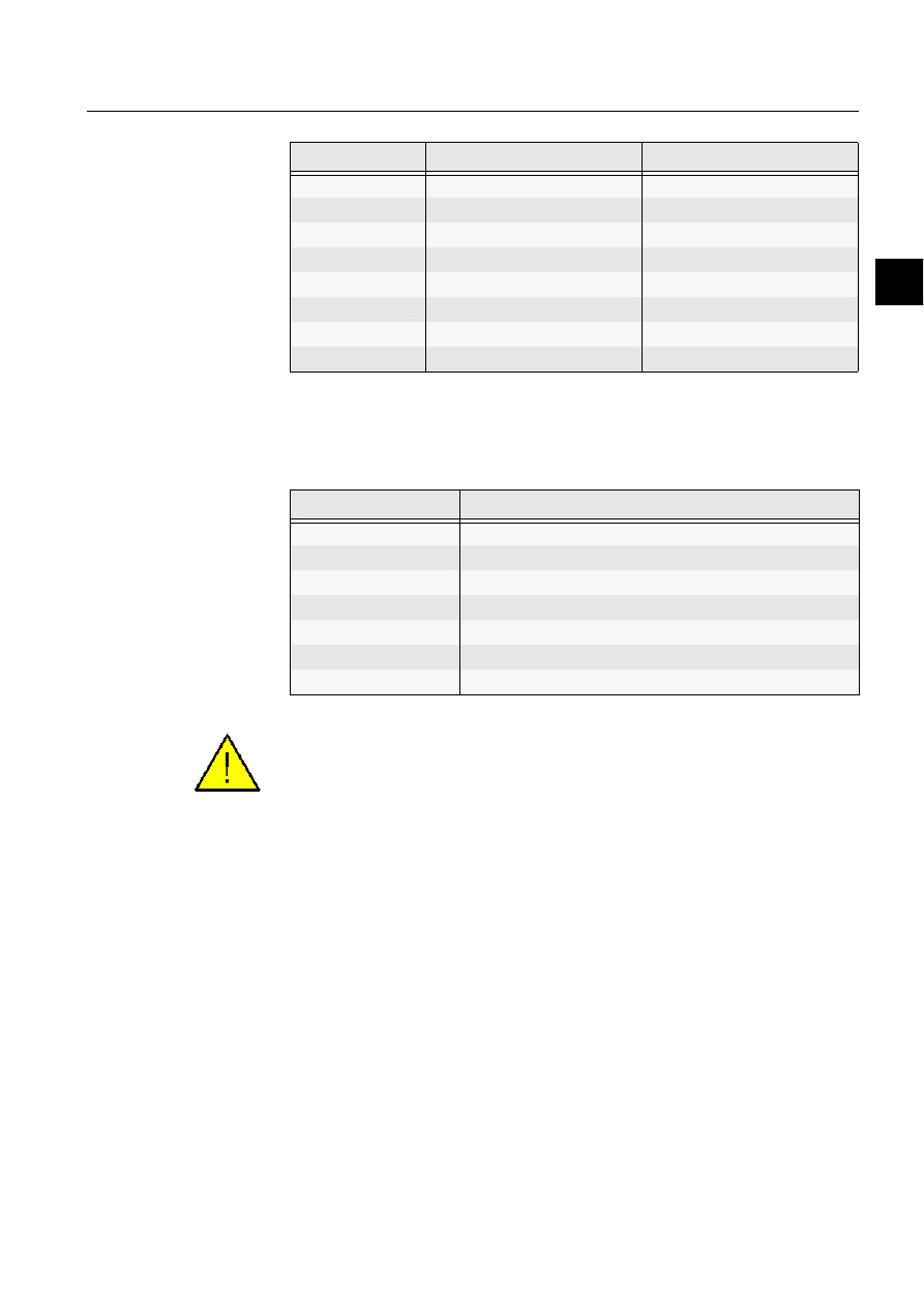
• Format_analog. The format of analog values. Valid values 5, 6 and 7 as shown in
Table 3.2.2-1 below.
Table 3.2.2-1
the format of analog values
* The most significant byte - the least significant byte order (and vice versa).
Debug parameters
• Debug_info. This parameter is only for debugging purposes and should be given
the value zero.
If the user wants to see the communication handling of the Modbus slave, value
20714 must be set to this parameter. We recommend only temporary use of this
debug mode.
Examples
This example shows the communication system configuration related to the example
of base system configuration earlier in this document. Two Modbus stations are
configured in this example.
[OwnNodeParameters]
own_node_no = 3
own_station_no = 203
[BaseSystem1]
basesystem_node_no = 9
basesystem_station_no = 209
tcp_ipadd = 194.142.148.36
application_number = 1
[SerialPortCommPar]
port_name = COM1
baud_rate = 1200 parity = 0
stop_bit = 0
data_bits = 8 flow_control = 0
[ModbusSlavePar]
address_offset = 0
modbus_master = 1
no_of_stns = 2
Value
Format
Description
5 WORD
Integer value, two bytes long (Unsigned if MicroSCADA is used as
Modbus master and Signed for any other Modbus master).
6
LONG
Signed 32 bit value, four bytes long in msb-lsb order*
7 MSB_LONG
Signed 32 bit value, four bytes long in lsb-msb order*

1MRS751864-MEN
COM 500
11
3. Instructions
Configuring MicroSCADA for Modbus
Slave Protocol
Configuration Guide
3
stn_no_1 = 1
stn_no_2 = 2
format_analog = 5
[Debug]
debug_info = 0
In order to add one more station with address 10 under the Modbus slave parameter,
add the following information:
no_of_stns = 3
stn_no_1 = 1
stn_no_2 = 2
stn_no_3 = 10
3.3.
After configuration
For each input signal from the process devices, the process database should contain
a process object whose value changes after the process data is received. The change
activates an event channel, which in turn starts a command procedure. The
command procedure sends the value to the CPI application program from which the
data is transferred to the Modbus master through the communication media.
Besides the configuration of the base and communication systems, you also need
to:
Configure the Modbus master.
Configure the base system for process communication.
Configure the process units.
Create and define input and output process objects for the process
communication. This is usually done when creating the station picture by using
standard functions from an application library.
Define event channels for the process objects.
Define command procedures for the event channels. For more information about
how to program the command procedures and values of the attributes, refer to
Chapter 4 of this document.
If COM 500 is used, the cross-references between the process objects and the
Modbus slave will be made in the COMTool. COM 500 creates the needed event
channels and command procedures automatically. For more information, refer to the
COM 500 Engineering manual.

12
1MRS751864-MEN
Configuring MicroSCADA for Modbus
Slave Protocol
COM 500
3.
Instructions
Configuration Guide
3.4.
Start-up
The Modbus Slave protocol runs in an external executable program and it must be
started separately. An automatic start of Modbus_Slave.exe can be done by
attaching a program link to the Start Menu, Programs, Startup menu in Windows.
How to test the configuration
MicroSCADA as the Modbus master
The configuration can be tested before the actual Modbus master is connected to the
system by using MicroSCADA as the Modbus master. By using this configuration
you are able to verify if the communication between the Modbus slave and master
is working properly.
The Modbus master protocol is implemented in the PC-NET software. The Modbus
master can be configured in the same computer as the Modbus slave or in a separate
computer.
To configure the base system as the Modbus master, the following base system
configuration should be made:
Define the base system, monitors and application, if they are not the same as
defined for the Modbus slave.
Define a node and a link for the NET unit.
Define the station type for the PLC stations (STY object number 28).
Define a PLC station for each station configured in the Modbus slave.
The following communication system configuration is required:
Define a Modbus master line.
Define the PLC stations with the same logical address as the RTU stations.
The station addresses (SA attribute) of the PLC stations should equal to the stn_no_*
parameters of the Modbus slave stations. Other attributes of the Modbus master line
and PLC stations should also match the configuration of the Modbus slave. For more
information on the attributes, see the System Objects manual.
([DPSOH
Listed below is an example for defining the station type and two PLC stations.
;Define station type
#CREATE STY:V = LIST(-
NA = "PLC",-
DB = "RTU" )
#CREATE STY28:B = %STY
;Define PLC stations.
#CREATE STA:V = LIST(-
TT = "EXTERNAL",-
ST = "PLC",-
ND = 1,-
TN = 1)

1MRS751864-MEN
COM 500
13
3. Instructions
Configuring MicroSCADA for Modbus
Slave Protocol
Configuration Guide
3
#CREATE STA1:B = %STA
#CREATE STA:V = LIST(-
TT = "EXTERNAL",-
ST = "PLC",-
ND = 1,-
TN = 2)
#CREATE STA2:B = %STA


1MRS751864-MEN
COM 500
15
4. Technical description
Configuring MicroSCADA for Modbus
Slave Protocol
Configuration Guide
4
4. Technical
description
4.1.
Modbus protocol
The Modbus Communications Protocol is an asynchronous, byte packaged protocol
used for communications between the master stations and Intelligent Electronic
Devices (IEDs) or Remote Terminal Units (RTUs). It provides a transport
mechanism for the master’s requests and RTU response messages. It supports one
single master station and up to 247 RTUs on a multi-drop line.
The Modbus protocol has two distinct modes: ASCII Modbus, which uses ASCII-
encoded hexadecimal messages and binary Modbus, which uses raw binary
messages. The Modbus slave implementation described in this document supports
only the binary mode.
All transactions are initiated by transmission of a request from the master station, an
RTU may not transmit unsolicited information. Every master station request must
be addressed to a specific RTU and some implementations of Modbus do not support
the broadcast message request type. A transaction consists of a single master station
request, followed by an RTU response or exception frame or a master station
timeout if no RTU response is generated.
4.2.
Communication
4.2.1.
CPI application program
The Modbus slave protocol is implemented in MicroSCADA by using
Communication Programming Interface (CPI) software. CPI is a collection of
functions written in C language suitable for implementing protocol converters
between the internal protocol of MicroSCADA and other protocols. The internal
protocol of MicroSCADA is used in communication between the MicroSCADA
nodes, for example, between a base system and a NET unit. The communication
between the CPI application program and the MicroSCADA base system is based
on TCP/IP network. The application program using CPI must emulate the RTU or
SPA device type.
4.2.2.
Connection to a MicroSCADA base system
The CPI application program establishes a connection to the base system with the
TCP/IP address as specified in the configuration. After establishing this connection,
a link will be established to the application specified in the configuration. The CPI
application program can access the MicroSCADA process database by using CPI
library functions.
MicroSCADA can have a number of slaves connected to it. The CPI application
program acts as a communication front-end. The stations configured in
MicroSCADA can also be logically created in the CPI application program. For
Modbus slave emulation, MicroSCADA is seen as a data collector. Each slave
connected to MicroSCADA is seen as a separate Modbus slave.
1MRS751864-MEN
16
1MRS751864-MEN
Configuring MicroSCADA for Modbus
Slave Protocol
COM 500
4.
Technical description
Configuration Guide
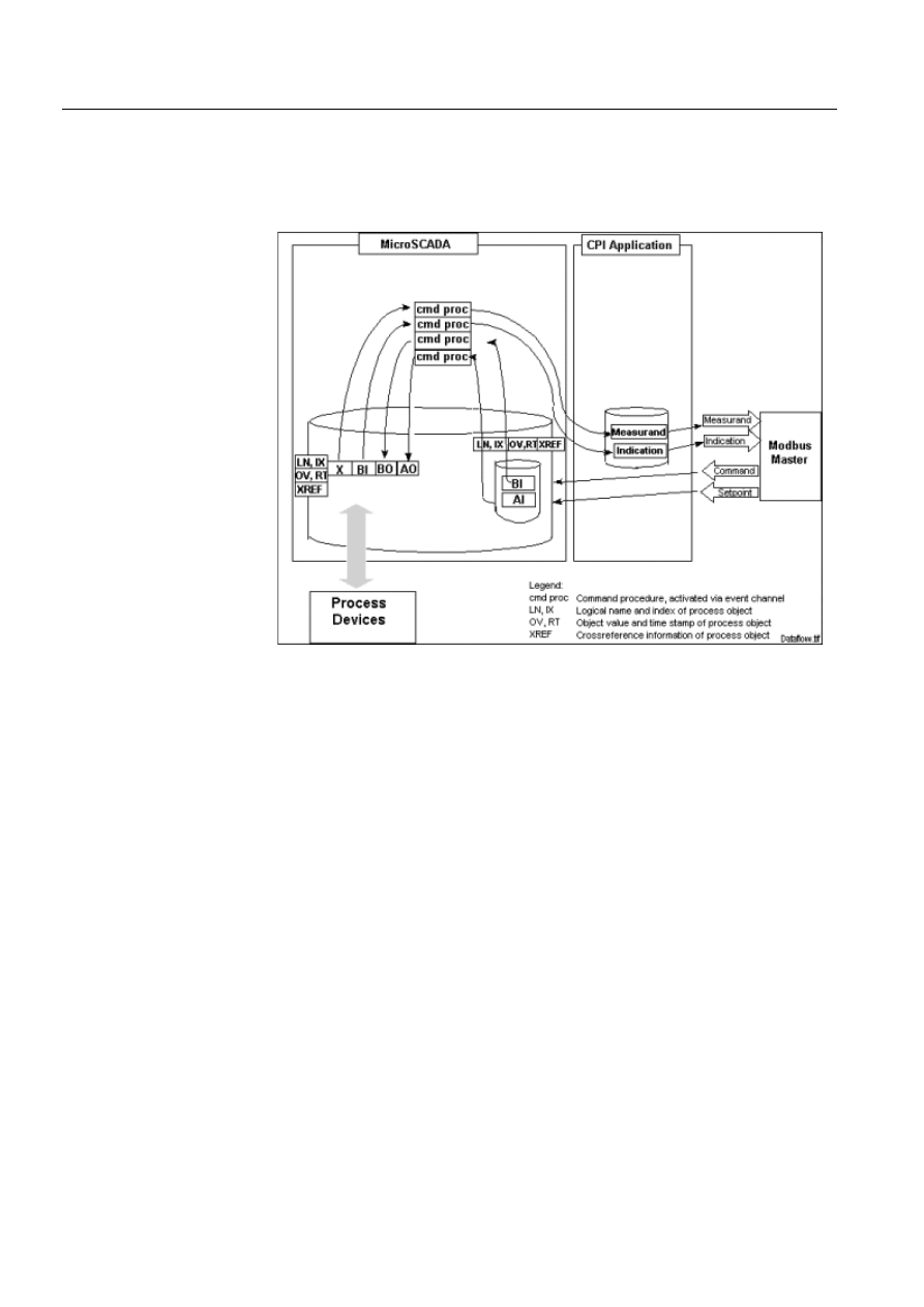
4.2.3.
Data flow
Figure 4.2.3.-1 describes the data flow between the process devices and the Modbus
master. Both directions are described separately since the data is handled in a
different way depending on the direction.
)LJ
'DWDIORZEHWZHHQWKHSURFHVVGHYLFHVDQGWKH0RGEXVPDVWHU
Input data
When input data, for example, indications and measured values are sent from the
process devices to the Modbus master, the following steps are taken:
The process devices sent the data to the MicroSCADA process database.
The updated process object activates an event channel.
The event channel executes a command procedure. Some of the attributes of the
process object are given as arguments to the command procedure.
The command procedure sends the data to the database of the CPI application
program based on specific cross-reference information.
The CPI application program sends the data to the Modbus master.
The cross-reference information is needed to deliver data to the database of the CPI
application program, for example, object address and message type. The number of
event channels and command procedures needed to deliver data to the master
depends on the application. One solution is to have one command procedure for each
process object type. Examples of the command procedures are given later in this

1MRS751864-MEN
COM 500
17
4. Technical description
Configuring MicroSCADA for Modbus
Slave Protocol
Configuration Guide
4
document. If COM 500 is used, all the needed command procedures and event
channels will be created automatically.
Output data
When output data, for example, object commands and analog setpoints are sent
from the Modbus master to the process devices, the following steps are taken:
The command is received by the MicroSCADA process database. There must
be a separate input process object for each Modbus command address. This part
of the process object is created manually when the signal engineering is done. It
can also be created automatically when COM 500 is used.
The updated process object activates an event channel.
The event channel executes a command procedure. Some of the attributes of the
process object are given as arguments to the command procedure.
The command procedure sends commands to the process devices by setting the
corresponding output process object(s) and, if required, sends a confirmation to
the Modbus master via the CPI application program.
Cross-reference data can also be used with commands. It can contain, for example,
information of the logical names and indices of the output process objects. Examples
of the command procedures are given later in this document.
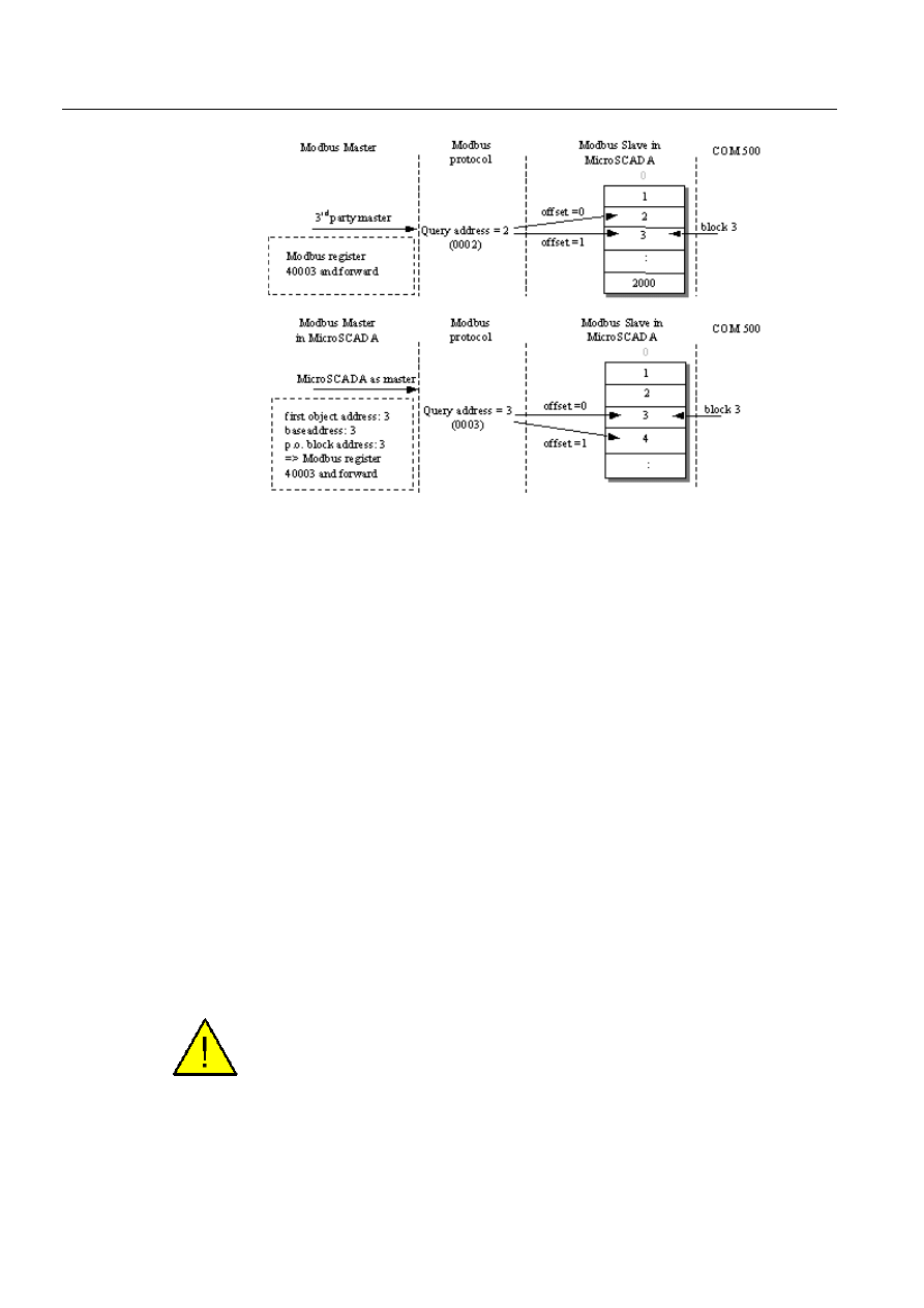
4.2.4.
Addressing schematics with Modbus protocol
Figure 4.2.4.-1 shows the addressing schema with analog values in the Modbus
protocol when using the Modbus Slave in MicroSCADA e.g.with the COM 500
application and a Modbus type of NCC. Analog values are mapped to address space
4xxxx in protocol definition. The memory area is not used in protocol queries and
responses, and it can be defined from the function type. Protocol addressing is
defined in following way: e.g. register 40001 is in query address 0000 and one
register is build up of 16 bits (word). If the 3rd party master uses an address offset,
the offset parameter must be set to 1. Then the wanted register number and the used
block number in MicroSCADA application match each other. If the offset parameter
is 0 in this case, it must be remembered that the used address is different in the
master and the slave.
If MicroSCADA is also the master system, the offset value should be set to 0.
MicroSCADA master queries do not use address offsets. Defined register in the
master configuration is shown in protocol with the same address number.
MicroSCADA configuration does not allow register address 0. Therefore, possible
block numbers are 1...2000 in the slave’s side.
18
1MRS751864-MEN
Configuring MicroSCADA for Modbus
Slave Protocol
COM 500
4.
Technical description
Configuration Guide
)LJ
7KHDGGUHVVLQJVFKHPDZLWKDQDORJYDOXHVLQWKH0RGEXVSURWRFRO
Offset parameter is also used with binary data. In MicroSCADA the discrete inputs
and coils of the Modbus slave are mapped to RTU like blocks. Possible block
address values are 1...125 and bit values 0...15. The Modbus protocol does not have
block definition for binary data, it only uses data grouping of 8 bits bytes in query
responses. Used memory area in protocol definition is 0xxxx. Coils and inputs are
addressed beginning from 1. However, in protocol queries the addressing begins
from bit 0.
If MicroSCADA is used as a master, the bit 0 in query and master database
configuration means block 1, bit 0 address in COM 500. In case of a 3rd party
master, the bit address is 1 in the slave, if the offset parameter is used. This schema
is used, if the master can define only binary addresses beginning from 00001.
It must be remembered that the defined topic base address in MicroSCADA master
affects the used bit address in the process object. For example, if the used base
address is 1 and bit 4 is wanted from the slave database, the BI process object bit
address is 4 (block 1). However, if the base address is 2 and the wanted input bit is
4, the used bit address must be 3. In this case block 1 begins from bit 2 instead of 1.
4.2.5.
Device communication attributes
The following attributes are used to exchange data between MicroSCADA and the
Modbus master. The attributes are similar to those of the RP 570 (SPI) stations with
a few exceptions.
The Modbus protocol does not contain an object status. The CPI application
program does not respond, if some or all of the data requested block has an object
status other than zero. This applies to analog input, as well as to single and double
indications, i.e. to function codes 1, 2, 3 and 4. If the Station In Use attribute is set
to zero, all the statuses will be 10. If the In Use attribute is 1, all the statuses will be
set to 2 to indicate suspicious values.

1MRS751864-MEN
COM 500
19
4. Technical description
Configuring MicroSCADA for Modbus
Slave Protocol
Configuration Guide
4
$9
$QDORJ9DOXH
Changes in analog measured values that are to be sent to the Modbus master are
written to this attribute. A vector is assigned to the AV attribute consisting of a time
stamp and analog value. The current value of the AV attribute with a certain address
(block number) can also be read back. Note that a read operation only returns the
VALUE of the attribute (not a vector).
Data type:
Vector
Value:
A vector of three elements:
(TIME, VALUE, STATUS)
TIME
Time stamp for the process object whose
value is sent
Time as RTU_ATIME format
VALUE
Analog value (scaled to -32768…32768)
STATUS
Status code as reported to the master.
Index range:
1…2000
Access:
Write only
([DPSOH
;set AV block nr. 100 to 1234, status = OK (= 0 )
#SET STA99:SAV(100) = (RTU_ATIME(%RT,%RM),1234,0)
The time stamp and status information is ignored in Modbus.
,'
,Q'LFDWLRQV
Indication changes that are to be sent to the Modbus master are written to this
attribute. The content of the attribute can be read back to a SCIL variable. Note that
the result of a read operation is a single integer rather than a vector. The integer
variable is a 16-bit bitmask that represents the state of all bits in this block.
Data type:
Vector
Value:
A vector with 4 … 6 elements as follows:
(TIME, BIT_NR, BIT_VAL, STATUS
[,ERMI_ENABLED[,TIME_QUALITY]])
TIME
Time stamp for the process object whose value is
sent.
Time is given in RTU_ATIME format
BIT_NR
The bit number for the changed bit (0...15)
BIT_VAL
0...1
[Note that the bit can be converted to a double-
indication by adding 128
10
to BIT_NR, which is
the number of the lower bit (0,2,4,...14). This
feature is included for compatibility with older
(ADLP-180) slave protocols. It is not
recommended to use it in new applications.]

20
1MRS751864-MEN
Configuring MicroSCADA for Modbus
Slave Protocol
COM 500
4.
Technical description
Configuration Guide
STATUS
This is the status reported to the master system in
IDS telegrams. The status value refers only to
bit_number and can be set individually for all
bits. Value range: integer 0 … 3:
Index:
1...125 (indication block number)
Access:
Write only
The time stamp and status information is ignored in Modbus.
,8
,Q8VH
The IU attribute indicates whether the station is in use or not.
Data type:
Integer
Value:
0 = not in use
1 = in use
Default value:
0
Access: No
limitations
',
'DWDEDVH,QLWLDOLVHG
The CPI application program sets DI to 0 at start-up. When MicroSCADA has
updated all the values in the CPI database, it sets this attribute to 1.The CPI
application program does not process any commands from the Modbus master
before DI equals 1.
Data type:
Integer
Value:
0 or 1
Access:
No limitations
3&
3XOVH&RXQWHU
Pulse counter values that are to be sent to Modbus master are written to this attribute.
The PC attribute is assigned a vector consisting of a time stamp, an end of period
flag and a pulse counter value.
The content of the attribute can be read back to a SCIL variable. Note that the result
of a read operation is a single integer rather than a vector. The integer variable
contains the last PC-value that was written to this block.
The pulse counter values are be stored as analog values in the CPI database. There
should not be any address clash between analog and pulse counter values.
Data type:
Vector
Value:
Vector (TIME, VALUE, STATUS)
Parameters are as in the AV attribute.
Index range:
1...2000
Access: Write
only
1MRS751864-MEN
COM 500
21
4. Technical description
Configuring MicroSCADA for Modbus
Slave Protocol
Configuration Guide
4
''
'RXEOH,QGLFDWLRQ
Double indications are sent to the CPI database using this attribute.
Data type:
Vector
Value:
(TIME, BIT_NR, BIT_VAL, STATUS
[,ERMI_ENABLED[,TIME_QUALITY]])
BIT_NR is 0, 2, 4, 6, 8, 10, 12 or 14
BIT_VAL is 0,1,2 or 3
Other parameters as in the ID attribute
Index:
1…125 (indication block number)
Access:
Write only
4.3.
Command procedures
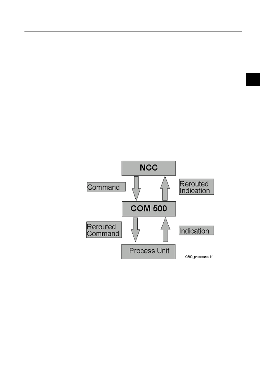
4.3.1.
Command procedures in COM 500
Signals are sent from the process units to the Modbus master and commands from
the Modbus master to the process units. COM 500 reroutes the signals using
command procedures and cross-references (see Figure 4.3.1.-1).
)LJ
&20UHURXWHVWKHVLJQDOV
If Modbus slave protocol is used with COM 500, the command procedures available
for COM 500 are used. The cross-reference information is entered in the Signal
Cross-Reference Tool. For more information, refer to the COM 500 Engineering
manual. Table 4.3.1-1 shows the used COM 500 command procedures and event
channels.

22
1MRS751864-MEN
Configuring MicroSCADA for Modbus
Slave Protocol
COM 500
4.
Technical description
Configuration Guide
Table 4.3.1-1
Used event channels and command procedures
4.3.2.
Command procedures in SYS 500
4.3.2.1.
Command procedures for process data
If SYS 500 is used, all read command procedures and event channels must be done
by the user. In the following chapter examples of command procedures are
described.
The attribute interface of the Modbus slave CPI application program is similar to the
one of the RP 570 slave (SPI) station type in MicroSCADA. Therefore, the
command process used with Modbus slave are similar to the procedures used with
RP 570 slave. Details of the attributes related to RP 570 slave stations can be found
in the System Objects manual.
The connection between the MicroSCADA process objects and messages to and
from the Modbus master is made by using cross-reference data. Cross-reference data
can be written to the FX (Free teXt) and FI (Free Integer) attributes of the process
objects by using the Process Object Definition Tool.
If COM 500 is used, the upstream cross-references for indications are stored in Free-
type process objects.
Cross-references for data transfer from MicroSCADA to the Modbus master are
written in the FX attribute, which is a string of max 30 characters. The general
syntax for a Modbus cross-reference is (an example of a syntax):
<STA_NUMBER.><BLOCK_NUMBER.>[<BIT_NUMBER.>]
STA_NUMBER:
Logical STA number (range 1...255). The value is stored
as 3 ASCII digits with leading spaces added if necessary.
FX string positions 1...3 are used for this value.
BLOCK_NUMBER:
The block number.of the Modbus master (range 1...125).
Stored as 3 ASCII digits with leading spaces added if
necessary. FX string positions 4...6 are used for this value.
BIT_NUMBER:
Bit number (range 0…15) is the bit position in the
indication data word. It is stored as ASCII digits with a
leading space added if necessary. FX string positions 7...8
are used for this value. The bit number is defined only
if the data point is to be sent to the Modbus master as an
indication. If it is sent e.g. as an analog value, it will be
undefined (but reserved).
Process Object Type
Event Channel
Command Procedure
Analog Input
COM_USAI
COM_USAI
Single Indication
COM_USDI
COM_USDI
Double Indication
COM_USDB
COM_USDB
Pulse Counter
COM_USPC
COM_USPC
Digital Commands
COM_DSBO
COM_DSBO
Analog Commands
COM_DSAO
COM_DSAO

1MRS751864-MEN
COM 500
23
4. Technical description
Configuring MicroSCADA for Modbus
Slave Protocol
Configuration Guide
4
The FI attribute is used for storing the object index. Modbus commands activate
digital and analog process input objects in MicroSCADA. The "real" output process
object has the same logical name as this input (i.e. it belongs to the same group), but
a different index. This index is kept in the FI attribute of the input object.
Analog inputs
Analog values are sent to the Modbus master as integers in the range -32768…
32768. All the analog signals must be scaled to this range (or part of it).
Analog values are sent to the Modbus master by using the AV attribute. The value
set to the AV attribute is:
(TIME, VALUE, STATUS)
The block number of the analog input is set to the index of the AV attribute.
Time and status information is not supported in the Modbus protocol and therefore
it is not sent to the master. However, status information will be stored in the CPI
application program and the analog value will be sent to the master only if the status
is OK.
All the analog values are connected to the same event channel/command procedure
combination. The command procedure is activated each time the process object is
updated. It reads the updated value, scales it and sends it to the CPI application
program. An example of the command procedure is listed below:
;read cross-reference data
@STA_NR = DEC_SCAN(SUBSTR(’LN’:PFX(’IX’),1,3))
@BLK_NR = DEC_SCAN(SUBSTR(’LN’:PFX(’IX’),4,3))
@VAL = ’LN’:POV(’IX’)
@T = RTU_ATIME(%RT,%RM)
;send value to CPI application
#SET STA’STA_NR’:SAV(%BLK_NR) = (%T,ROUND(%VAL),0)
Single indications
All the binary inputs are connected to an event channel/command procedure
combination. The command procedure is activated each time the process object is
updated. It reads the updated value and sends it to the CPI application program.
Single indications are sent to the Modbus master by using the ID attribute. The
value set to the ID attribute is:
(TIME, BIT_NUMBER, BIT_VALUE, STATUS)
The block number of the single indication is set to the index of the ID attribute.
An example of a command procedure handling single indications is listed below.
Note that zero status is assumed.
;read cross-reference data
@STA_NR = DEC_SCAN(SUBSTR(’LN’:PFX(’IX’),1,3))
@BLK_NR = DEC_SCAN(SUBSTR(’LN’:PFX(’IX’),4,3))
@BIT_NR = DEC_SCAN(SUBSTR(’LN’:PFX(’IX’),7,2))
@T = RTU_ATIME(%RT,%RM)
;send value to CPI application, assume ok status
#SET STA’STA_NR’:SID(%BLK_NR)=(%T,%BIT_NR,%BI,0)

24
1MRS751864-MEN
Configuring MicroSCADA for Modbus
Slave Protocol
COM 500
4.
Technical description
Configuration Guide
It is not possible to send time stamp and status information in Modbus messages.
The CPI application program ignores time stamp information. Status information,
however, is handled by the CPI application program to some extent.
Double indications
Double indications are not supported directly in the Modbus protocol. Double
indications are converted into two single indication messages by the CPI application
program.
Double indications are sent to the Modbus master by using the DD attribute. The
value set to the DD attribute is:
(TIME, BIT_NUMBER, BIT_VALUE, STATUS)
The block number of the single indication is set to the index of the DD attribute.
;read cross-reference data
@STA_NR = DEC_SCAN(SUBSTR(’LN’:PFX(’IX’),1,3))
@BLK_NR = DEC_SCAN(SUBSTR(’LN’:PFX(’IX’),4,3))
@BIT_NR = DEC_SCAN(SUBSTR(’LN’:PFX(’IX’),7,2))
;send value to CPI application
@T = RTU_ATIME(%RT,%RM)
#SET STA’STA_NR’:SDD(%BLK_NR) = (%T,%BIT_NR,%DB,0)
It is not possible to send time stamp and status information in Modbus messages.
The CPI application program ignores time stamp information. Status information,
however, is handled by the CPI application program to some extent.
Pulse counters
The pulse counter values are treated as analog values by the Modbus slave. The
pulse counter values are sent to the Modbus master by using the PC attribute. The
value set to the PC attribute is:
(TIME, VALUE, STATUS)
The block numbers of analog and pulse counter objects should be different since
they are both treated as analog values.
;read cross-reference data
@STA_NR = DEC_SCAN(SUBSTR('LN':PFX('IX'),1,3))
@BLK_NR = DEC_SCAN(SUBSTR('LN':PFX('IX'),4,3))
;send value to CPI application
@T = RTU_ATIME(%RT,%RM)
#SET STA’STA_NR’:SPC(%BLK_NR) = (%T,%PC,0)
4.3.2.2.
Command procedures for commands
Since MicroSCADA application sees the CPI program as an RTU type station, data
that is transferred from the master to the slave must be handled as input data. When
this kind of input is updated, the value is read by a command procedure and, if
necessary, converted before it is written to the actual output object. The command
procedure is activated through an event channel which is bound to the input object.

1MRS751864-MEN
COM 500
25
4. Technical description
Configuring MicroSCADA for Modbus
Slave Protocol
Configuration Guide
4
It is also possible to utilise input data to perform arbitrary internal operations in the
application program.
The procedures that are presented below cover the basic cases, when SINCDAC
commands and setpoints are mapped directly to the corresponding output objects. If
a more complex relationship between the input and output objects is needed, it will
be necessary to build application specific command procedures.
Process commands
Process commands from the Modbus master are handled as digital inputs, with
object address (OA attribute) in the range 0…2000 (object commands). When the
CPI application program receives a process command message, it reads the object
number (register address) from the message. It also activates a MicroSCADA
process object with the corresponding object address and sets its value according to
the command (1 = ON, 0 = OFF).
The command is transferred to a binary output process object with a command
procedure. The cross-reference between the input and output object is accomplished
by using the same logical name, but different indexes, for the input and output
objects. Input objects hold the index of the corresponding output object in their FI
attribute. This makes it possible to use a common command procedure for most
process commands. Only those commands that require validity checking or other
special processing will need individual SCIL procedures.
Below is a command procedure that is used when no special processing is needed.
;read cross-reference data
@OBJ_IX = ’LN’:PFI(%IX)
;set value to output object
#SET ’LN’:PBO(%OBJ_IX) = %DI
Analog setpoints
Analog commands from the Modbus master can be received by analog input process
objects. The object address range start from 3000 (decimal). The block number
(register address) is added to get the address that is used for a particular setpoint.
Analog setpoints are received as integers in the range -32768… 32768 and may have
to be scaled.
An example of a command procedure for handling analog setpoints:
;read cross-reference data
@OBJ_IX = ’LN’:PFI(%IX)
;scale value
@VAL = %AI-’SC’:XSC(1)
@VAL = %VAL / (’SC’:XSC(2)-’SC’:XSC(1))
@VAL = %VAL * (’SC’:XSC(4)-’SC’:XSC(3))
@VAL = %VAL + ’SC’:XSC(3)
;set value to output object
#SET ’LN’:PAO(%OBJ_IX) = %VAL

26
1MRS751864-MEN
Configuring MicroSCADA for Modbus
Slave Protocol
COM 500
4.
Technical description
Configuration Guide
4.4.
Function codes
The used CPI application program is for Modbus slave protocol in MicroSCADA.
The Modicon modbus protocol has many function codes. There are different types
of Modicon controllers available which supports different types of functions. There
are 24 functions supported in Modbus protocol. All the controllers do not necessarily
support all the functions. The Modbus function codes implemented in the Modbus
CPI application program are 1, 2, 3, 4, 5, 6, 8, 11, 15 and 16. An exception response
will be sent to all other Modbus function codes. For details of exception responses,
refer to the Modbus Modicon Protocol Reference Guide.
The function codes implemented in this version of software are 1, 2, 3, 4, 5, 6, 8, 11,
15 and 16. These function codes can access the CPI database, which reflects the data
in the MicroSCADA process database.
According to the Modbus protocol, all the data is stored in registers or coils. Each
register consists of 2 bytes and each coil consists of one ON/OFF bit.
There are four different addressable memory areas in the Modbus protocol as shown
in Table 4.4.-1.
Table 4.4.-1 Modbus memory areas
These memory areas can be accessed by using different function codes as shown in
Table 4.4.-2
Table 4.4.-2 Function codes and the corresponding memory areas
In the Modbus CPI application program there is no difference in the handling of
function codes 1 and 2, as well as function codes 3 and 4. Function codes 1 and 2
access the same data. This is also the case with function codes 3 and 4.
Table 4.4.-3 lists the Modbus function codes and the used process object types.
Address
Description
00001…09999
Discrete Outputs
10001…19999
Discrete Inputs
30001…39999
Input Registers
40001…49999
Holding Registers
Function Code
Description
Memory area
01
Read coil status
00001…09999
02
Read input status
10001…19999
03
Read holding register
40001…49999
04
Read input registers
30001…39999
05
Force single coil
00001…09999
06
Write single register
40001…49999
15
Force multiple coils
00001…09999
16
Write multiple registers
40001…49999
1MRS751864-MEN
COM 500
27
4. Technical description
Configuring MicroSCADA for Modbus
Slave Protocol
Configuration Guide
4
Table 4.4.-3 Function codes and the corresponding process object types
Table 4.4.-4 shows the subfunction codes of the function code 8. This function does
not affect the CPI database, which means that the process database is not affected.
Some subfunction codes update the diagnostic counters in the CPI database.
Table 4.4.-4 Subfunction codes of function code 8
The broadcast mode is not supported by any of the function codes.
4.4.1.
Function codes for process data
4.4.1.1.
Function code 01 - Read coil status
This function reads the value (ON/OFF) of coils from the specified address. The
function can access single and double indication process objects via the CPI
database. Modbus protocol does not allow direct transmission of double indication.
Double indication will be transmitted as two single indications to the Modbus
master. This has to be taken care of at the master’s side. For double indications the
least significant bit will be transmitted first and the most significant bit last.
The query message contains the following information:
• Slave address
• Function code
• Start coil address high
Function Code
Description
Process Object Type
01
Read coil status
Indication (single & double)
02
Read input status
Indication (single & double)
03
Read holding register
Analog Input
04
Read input registers
Analog Input
05
Force single coil
Digital input
06
Write single register
Analog Input
15
Force multiple coils
Digital Input
16
Write multiple registers
Analog Input
Subfunction Code
Description
00
Return query data
01
Restart communication option
10
Clear counters and diagnostic register
11
Return bus message count
12
Return bus communication error count
13
Return exception count
15
Return slave no response count

28
1MRS751864-MEN
Configuring MicroSCADA for Modbus
Slave Protocol
COM 500
4.
Technical description
Configuration Guide
• Start coil address low
• Number of coils high
• Number of coils low
• CRC - error check
Slave address is the logical station address from which the data is requested. The coil
address depends on the process object address.
The coil address for a process object is calculated in the following way:
Coil address = 16 * (block number-1) + bit no + 1
The block number for a coil address is calculated in the following way:
Block number = (Coil address - 1 - bit no) / 16 + 1
([DPSOHV
Coil address for a process object with block number 2 and bit number 0:
Coil address = 16 * (block 2 number -1) + bit no 0 + 1 = 17
For a double indication with block number 3 and bit number 2:
Coil address1 = 16 * (3-1) + 2 +1 = 35
Coil address2 = 16 * (3-1) + (2 +1) + 1 = 36
The address range is 1…2000. If some or all of the requested data is outside this
address range, an exception response will be sent indicating an illegal address value.
The response message contains the following information:
• Slave address
• Function code
• Number of bytes
• Data high
• Data low
• CRC - error check
The number of coil values that can be read at a time depends on the master. The slave
has no limitations in this regard.
4.4.1.2.
Function code 02 - Read input status
This function is equivalent to function 01 described above.
4.4.1.3.
Function code 03 - Read holding registers
This reads analog values from the holding registers. The function can access analog
input process objects from the process database. Different types of formats are
available for reading the data as shown in Table 4.4.1.3-1

1MRS751864-MEN
COM 500
29
4. Technical description
Configuring MicroSCADA for Modbus
Slave Protocol
Configuration Guide
4
Table 4.4.1.3-1
Formats of analog data
* The most significant byte - the least significant byte order (and vice versa).
The format of analog data is defined in Modbus_Slave with the Format_analog
parameter in the config.ini. This parameter affects all the analog values.
The format configured in the configuration will be used. If format 5 is used each data
will be two bytes long. The format has to be chosen based on the master. All the
above formats are implemented in the MicroSCADA master.
If format 6 or 7 is used, it must be remembered that a single value takes two blocks
from the address base.
The query message contains the following information:
• Slave address
• Function code
• Start register address high
• Start register address low
• Number of registers high
• Number of registers low
• CRC - error check
Slave address is the logical station address from which the data is requested. The
start register address is same as the block number of the first process object. For
example, if the block number of a process object is 10, the register address will be
10 as well.
The address range is 1…2000. Any request of data outside this range will result in
exception response.
The number of bytes that can be requested in one message depends on the master.
The slave has no limitation on this.
4.4.1.4.
Function code 04 - Read input registers
This function code is equivalent to function code 03 described above.
4.4.2.
Function codes for commands
4.4.2.1.
Function code 05 - Forcing a coil
This function will force the value of a coil to be either 0 or 1. This function sends an
object command in case MicroSCADA is the Modbus master. When this message is
received from the master, the slave will treat this as a digital value and forces this
process object to 1 or 0. The command procedure in MicroSCADA Modbus slave
Format Type
Code
Description
WORD
5
Integer value, two bytes long (unsigned for MicroSCADA
Modbus master and signed for any other Modbus master).
WORD
6
Signed 32 bit value, four bytes long in msb-lsb order*
MSB_LONG
7
Signed 32 bit value, four bytes long in lsb-msb order*

30
1MRS751864-MEN
Configuring MicroSCADA for Modbus
Slave Protocol
COM 500
4.
Technical description
Configuration Guide
will forward these commands to the process side. For more information about this
subject, see the Process commands in Section 4.3.2.2.
The query message contains the following information:
• Slave address
• Function code
• Coil address high
• Coil address low
• Forcing value high (00 or FF hexadecimal)
• Forcing Value low (00 hexadecimal)
• CRC - error check
The slave address is the logical address of a station to which the command is sent.
The coil address is the object number of the process object. For example, if the block
number of an object command is 100, the coil address will be 100 as well. The
normal response message to this query is an echo of the query itself.
4.4.2.2.
Function code 06 - Modify register content
This function code sets a single register to a particular value specified in the query
message. In case of the MicroSCADA Modbus master, this will be an analog set
point. The command procedures will forward these commands to the process side.
For more information about this subject, see Analog setpoints in Section 4.3.2.2.
At the slave’s side this command will modify the corresponding analog input
process object with the object address 3000 analog offset + register address.
The query message contains the following information:
• Slave address
• Function code
• Register address high
• Register address low
• Data high
• Data low
• CRC - error check
The slave address is the logical address of a station to which this command is sent.
The register address is same as the object address of the process object. For example,
if the object number is 200, the register address will be 200. The valid address range
is 1…2000. Any register address outside this range will result in exception response.
Only two-byte signed integer values can be sent to the slave. If floating point values
are sent, the decimal portion will be truncated.
4.4.2.3.
Function code 08 - Diagnostics
This function serves to check the communication between the slave and the master.
The following sections describe the subfunction codes of the function code 8.

1MRS751864-MEN
COM 500
31
4. Technical description
Configuring MicroSCADA for Modbus
Slave Protocol
Configuration Guide
4
Subfunction code 00 - Return query data
The data passed in the query data field is to be returned in the response. This is just
for checking the line between the slave and the master.
Both the query and response messages contain the following information:
• Slave address
• Function code
• Subfunction code high
• Subfunction code low
• Data field high
• Data field low
• CRC - error check
Subfunction code 01 - Restart communication option
If the slave is in the Listen Only mode, no response will be sent to the master but the
slave will be forced out of the Listen Only mode. If the Listen Only mode is not used,
a normal response will be sent. The query structure is the same as above.
This message sent to any of the slaves in MicroSCADA forces all the stations
connected to it out of the Listen Only mode. However, restart will be considered as
a station-specific message.
Subfunction code 10 - Clear counters and diagnostic register
The diagnostic register is not relevant to MicroSCADA. This function clears all the
counters. Counters are also cleared on power up. There is only one set of diagnostic
counters for the MicroSCADA Modbus slave. There are no separate counters for
individual stations connected to MicroSCADA. This applies wherever counters are
mentioned. The query and response is the same as above.
Subfunction code 11 - Return bus message count
The response data field contains the quantity of messages that the slave has detected
on the communication system since power up as follows:
• Slave address
• Function code
• Subfunction code high
• Subfunction code low
• Data field high
• Data field low
• CRC - error check
Subfunction code 12 - Return bus communication error count
The response data field returns the number of CRC errors encountered by the slave
since its last restart or power up.
The query and return messages contain the following information:

32
1MRS751864-MEN
Configuring MicroSCADA for Modbus
Slave Protocol
COM 500
4.
Technical description
Configuration Guide
• Slave number
• Function code
• Subfunction code high
• Subfunction code low
• Data field high
• Data field low
• CRC - error check
Subfunction code 13 - Return bus communication error count
The response data field returns the quantity of Modbus exception responses. The
query and return fields are the same as in code 12.
Subfunction code 14 - Return slave message count
The response data field returns the quantity of messages addressed to the slave
which the slave has processed since start-up. The query and response fields are the
same as in code 12.
Subfunction code 15 - Return slave no response count
The response data field returns the quantity of messages addressed to the slave for
which no response has been returned. The query and response fields are the same as
in code 12.
For subfunction codes 03, 16, 17, 18, 19 and 20
the data field of the response will be
filled with zeros because these function codes are either hardware dependent or not
relevant.
The subfunction code 21 is not supported.
4.4.2.4.
Function code 11 - Fetch communication event counter
This function code returns a status word and an event count (2 bytes each). The event
count is incremented for each successful message completion. This counter is not
incremented for exception responses or fetch event counter commands. The events
counter can be reset by function code 8.
The status word will be FFFF (hexadecimal), if the slave is busy. Otherwise the
status word will be zero.
The query message contains the following information:
• Slave address
• Function code
• CRC-error check
The response message contains the following information:
• Slave address
• Function code

1MRS751864-MEN
COM 500
33
4. Technical description
Configuring MicroSCADA for Modbus
Slave Protocol
Configuration Guide
4
• Status high
• Status low
• Event count high
• Event count low
• CRC - error check
There is no individual counter for each station connected to MicroSCADA but only
one event counter common to all the stations.
4.4.2.5.
Function code 15 - Force multiple coils
This function code sets a number of commands in one Modbus message. The current
version of MicroSCADA Modbus master does not support this function code. The
slave treats these commands as digital inputs and stores them also as such. This
function code is equivalent to function code 5 described earlier.
The maximum number of commands that can be sent in one message is limited to
50. If the master tries to send more than 50 commands in one message, an exception
response with an error code will be sent to the master. The valid address range is
1…2000. Any value outside this range will result in an exception response.
4.4.2.6.
Function code 16 - Modify multiple registers
This is similar to function code 6 with only one difference: it handles multiple
commands. The commands are treated as analog input values at the slave’s side with
an object number 3000 + register address. This function code is equivalent to
function code 6 described earlier.
The maximum number of commands that can be sent in one message is limited to
50. If more than 50 commands are sent in one message, an exception response will
be sent to the master. The valid address range is 1…2000. Any value outside this
range will result in an exception response.
Status codes
The following status codes are defined:
13450
SPIC_INVALID_INDEX_RANGE
13451
SPIC_UNKNOWN_SPI_ATTRIBUTE_VALUE
13455
SPIC_UNKNOWN_SPI_ATTRIBUTE
13459
SPIC_FCOM_COLDSTART_RECEIVED
13469
SPIC_ARGUMENT_EXPECTED
13470
SPIC_TOO_MANY_ARGUMENTS
13484
SPIP_COMMUNICATION_WITH_CS_LOST
13485
SPIP_COMMUNICATION_WITH_CS_ESTABLISHED
14016
NETW_UNKNOWN_DESTINATION_DEVICE
When used with COM 500, only the following error codes are available:
13459
SPIC_FCOM_COLDSTART_RECEIVED
13484
SPIP_COMMUNICATION_WITH_CS_LOST
13485
SPIP_COMMUNICATION_WITH_CS_ESTABLISHED


COM 500
Index
Configuration Guide
Index
Page
$
Address_offset
Addressing schematics
Analog
&RPPDQGV
,QSXWV
2IIVHWV
6HWSRLQWV
9DOXHV
............................................................................................... 17
Analog Value
AV
%
Base system as Modbus master
..................................................................................... 12
Binary inputs
Bit number
Block number
Broadcast mode
&
Clear counters and diagnostic register
........................................................................... 31
Coil address
COM 500
Command procedures
Communication attributes
............................................................................................. 18
Communication frontend
............................................................................................... 15
Communication Programming Interface (CPI)
............................................................. 15
Config.ini
Configuration
Configuration test
CPI application
CPI database
CRC error
Cross-reference information
.......................................................................................... 16
'
Data flow
Database Initialised
DD
Debug parameters
DI
Diagnostics
Digital
&RPPDQGV
,QSXWV
Directory
?SURJ?0RGEXVB6ODYH
................................................................................................5
Discrete inputs
Double Indication
.......................................................................................21
1MRS751864-MEN
Configuring MicroSCADA for Modbus
Slave Protocol

1MRS751864-MEN
Configuring MicroSCADA for Modbus
Slave Protocol
COM 500
Index
Configuration Guide
(
Error codes
)
Fatal error
Fetch communication event counter
............................................................................. 32
FFFF
FI
Force multiple coils
................................................................................................. 26
Force single coil
Forcing a coil
Free Integer
Free teXt
Function codes
FX
*
General parameters
,
ID
In Use
InDications
Input data
Intelligent Electronic Devices (IEDs)
........................................................................... 15
IU
/
LAN link
0
Modbus slave
Modbus slave application program
................................................................................. 8
Modbus_slave.exe
Modicon Modbus protocol
...................................................................................... 15
Modify multiple registers
.............................................................................................. 33
Modify register content
................................................................................................. 30
1
ND
2
OA
Object address
Object index
Offset parameter
Output data
3
PC
PC-NET
PLC stations

1MRS751864-MEN
COM 500
Index
Configuring MicroSCADA for Modbus
Slave Protocol
Configuration Guide
Process commands
Protocol addressing
Protocol queries
Pulse Counter
5
Read coil status
Read holding register
Read holding registers
Read input registers
.................................................................................................26
Read input status
Register number
Remote Terminal Units (RTUs)
..................................................................................... 15
Response message
Restart communication option
....................................................................................... 31
Return bus communication error count
...................................................................31
Return bus message count
............................................................................................. 31
Return query data
Return slave message count
.......................................................................................... 32
Return slave no response count
..................................................................................... 32
RP 570 station
RTU station
6
SA
Serial port communication parameters
............................................................................ 8
Signals
SINCDAC
Single indications
SPI station
Status codes
Status information
SYS 500
SYS_BASCON.COM
7
TCP/IP
Time stamp
:
Write multiple registers
................................................................................................. 26
Write single register

Document Outline
- Introduction
- Safety information
- Instructions
- Technical description
Wyszukiwarka
Podobne podstrony:
Configuring MicroSCADA for Modbus Master Protocol
Configuring MicroSCADA for DNP V3 00 Slave Protocol
Configuring MicroSCADA for IEC 60870 5 101 Slave Protocol
Configuring MicroSCADA for IEC 60870 5 104 Slave Protocol
Configuring MicroSCADA for IEC 60870 5 103 Master Protocol
Configuring MicroSCADA for IEC 60870 5 104 Master Protocol
Configuring MicroSCADA for DNP V3 00 Master Protocol
Configuring MicroSCADA for IEC 60870 5 101 Master Protocol
Configuring MicroSCADA for OPC DA Client
23 299 318 Optimizing Microstructure for High Toughness Cold Work Steels
MODBUS Application Protocol V1 1b
23 299 318 Optimizing Microstructure for High Toughness Cold Work Steels
Confocal optics microscopy for biochemical and cellular high throughput screening by Lenka Zemanová,
37 509 524 Microstructure and Wear Resistance of HSS for Rolling Mill Rolls
Installing WSUS for Configuration Manager 2012 R2
Słownik, ACPI (Advanced Configuration and Power Interface): Standard zarządzania energią wypracowany
Słownik, ACPI (Advanced Configuration and Power Interface): Standard zarządzania energią wypracowany
więcej podobnych podstron