
all, what good is information if it can’t be used, sold, or
shared? The much-ballyhooed “information superhighway” would be
nowhere without the extensive telephone network already in place
necessary to tie everything together. That the network is increasing in
handling capability every day through the expanding use of fiber and
microwave is a testament to this communications explosion.
While businesses have come to depend on an internal phone system
to ease peer-to-peer communications, the convenience afforded by such a
system, for the most part, hasn’t made the jump to the home. In our first
article, we take a look at a simple in-home PBX that uses regular telephones
for performing intercom-like functions. The same project can be used as a
base for future expansion to extend the capabilities to the outside world.
Next, garbled data is as good as no data at all, so any information
transfer over imperfect communications lines must include some kind of
error detection or correction. The
error detection and correction code
was first theorized back in 1949, but it’s finding uses in many of today’s
applications.
While perfect data is important, often that data must also be protected
from prying eyes. Data encryption is a hot topic of debate these days, with
the Federal Government getting involved in the latest round. Our third article
looks at some of the current issues to give you an idea of what some of your
elected officials are doing.
In our final feature article, we extend the usefulness of the popular and
low-cost RS-485 network to accommodate more than 32 devices, longer
cable runs, and more flexible network topologies.
In this month’s columns, Ed bows to popular demand by starting a
series of articles on how to do protected mode programming on the
Jeff finishes up his exoskeleton project with some support software. Tom
has finally recovered from last month’s journey to LA with a look at an
emerging standard that promises to ease the task of wireless communication
between palmtop and handheld computing devices. Finally, John continues
his
coverage by writing some reusable software.
2
Issue July 1994
The Computer Applications Journal
CIRCUIT CELLAR
THE COMPUTER
APPLICATIONS
JOURNAL
FOUNDER/EDITORIAL DIRECTOR
Steve Ciarcia
EDITOR-IN-CHIEF
Ken Davidson
TECHNICAL EDITOR
Michael Swartzendruber
ASSOCIATE EDITOR
Rob
ENGINEERING STAFF
Jeff Bachiochi Ed Nisley
WEST COAST EDITOR
Tom Cantrell
CONTRIBUTING EDITORS
John Dybowski Russ Reiss
NEW PRODUCTS EDITOR
Weiner
PUBLISHER
Daniel Rodrigues
PUBLISHER’S ASSISTANT
Sue
Hodge
CIRCULATION COORDINATOR
Rose
CIRCULATION ASSISTANT
Barbara
CIRCULATION CONSULTANT
Gregory
BUSINESS MANAGER
Jeannette Walters
ADVERTISING COORDINATOR
Dan Gorsky
CIRCUIT CELLAR INK, THE COMPUTER
JOURNAL
is published
monthly by Circuit Cellar Incorporated, 4 Park Street,
ART DIRECTOR
Lisa Ferry
Suite 20, Vernon, CT
(203)
Second
One-year (12 issues) subscription rate U.S.A. and
GRAPHIC ARTIST
Joseph
tries $49.95. All subscription orders payable in U.S.
funds only, via international postal money order or
check drawn on U.S. bank. Direct
orders
and subscription related questions to The Computer
Applications Journal Subscriptions, P.O. Box 7694,
NJ 08077 or call (609) 766.0409.
POSTMASTER: Please send address changes to The
CONTRIBUTORS:
Jon Elson
Tim
Frank Kuechmann
Kaskinen
Cover Illustration by Bob Schuchman
PRINTED IN THE UNITED STATES
Applications Journal, Circulation Dept., P.O.
7694,
NJ 06077
ASSOCIATES
NATIONAL ADVERTISING REPRESENTATIVES
NORTHEAST
SOUTHEAST
Debra Andersen
Collins
WEST COAST
Barbara Jones
(617) 769-8950
Fax:
(617) 769-8982
MID-ATLANTIC
Barbara Best
(305) 966-3939
Fax: (305) 985-8457
MIDWEST
Nanette Traetow
Shelley Rainey
(714) 540-3554
Fax: (714) 540-7103
(908) 741-7744
Fax: (908) 741-6823
(708) 789-3080
Fax: (708) 789-3082
bps,6
stop
9600 bps Courier HST, (203)
All programs and schematics
Circuit
been carefully reviewed to ensure
performance
by subscribers.
kind for
these
programs or schematics for the consequences of any such errors. Furthermore, because of possible
in the quality and condition of materials and workmanship of reader-assembled projects,
Circuit Cellar INK
disclaims any
for the safe and proper function reader-assembled projects based upon or from
plans, descriptions, or information published in
Cellar
INK.
Entire contents copyright 1994 by Circuit Cellar Incorporated. All rights reserved. Reproduction of this
whole or
without written consent from Circuit Cellar Inc. prohibited.
1 4
2 4
3 6
4 0
4 8
5 8
Editor’s INK
Ken Davidson
Information Society
Reader’s INK
Letters to the Editor
New Product News
edited by
Weiner
The Personal PBX
by Richard Newman
Using the
Error Detection and Correction Code
by Hank Wallace
The Great Encryption Debate
by
Take a Bus to the Nearest Star/The Star-485 Adds
Flexibility to any RS-485 Network
by Michael Swartzendruber
Firmware Furnace
Journey to the Protected Land:
The ‘386SX
Takes the First Step
Ed Nisley
From the Bench
Virtual Reality Requires Real Data/
Part II-A Simple Matter of Software
Bachiochi
Silicon Update
IR Babel Buster
Tom Can
Embedded Techniques
Add Some Code to the
Dybowski
t h e
Steve’s
Own INK
Steve Ciarcia
One Man’s Junk...
Advertiser’s Index
The Computer Applications Journal
Issue
July 1994
3

AVMux Clarifications
Thank you, Steve, for the plug you gave Maxim’s
video products in your article “Control Your Audio/
Video Connections with the AVMux” (April 1994). The
circuits are extremely interesting and I for one am
anxious to build it as are some other engineers (who are
not employed by Maxim).
For completeness, I should point out a minor error
in the schematic of Figure 5. I know you may have been
led astray by our MAX456 data sheet, so I do place the
blame on Maxim and not you. In Figure 5, the inputs
should be terminated with
resistors since the
MAX456 does not contain an input termination resistor.
Additionally, the output lines may confuse some people.
The
resistors to ground at outputs 1-8 are meant
to represent the total load. If the builder’s equipment
contains a
termination, the resistor(s) should be
eliminated. They were included in the data sheet
schematic only to show that the
cable must be
terminated at the load end.
Another point is that the note under Figure 5
indicates the use of “shielded cable.” There are many
types of shielded cable, but in video circuits you want to
use a
coaxial cable such as
For your readers’ further information, Maxim has
just introduced the MAX458 and MAX459 crosspoint
video switches. These are 8 x 4 (8 in/4 out) devices that
contain amplifiers capable of driving a
back
terminated cable. The MAX459 is a gain-of-2 device to
enable the user to achieve a total throughput gain of 1
when driving a back-terminated cable. The MAX458
gain is 1 and is particularly useful when building larger
arrays.
Joe Stern
Applications Engineer
Maxim Integrated Products
Sunnyvale,
Last Word on Program Labels
Jeff Mills’s program-labeling technique (“Reader’s
INK,” May 1994) leaves a lot to be desired. His examples
may be useful for simple
programs, but labels
should tell me what the code is doing. For example, I
prefer calling a routine labeled C R L F instead of
when it comes to putting out simple carriage return and
bytes. When I look at CALL C RL in the midst
of 5000 lines of code, I have a good idea of what the code
should do. CALL
tells me nothing. Also, when the
jump to
C R L F routine finishes, I’d much rather have
thanjumpto
Jon Titus
Milford, Mass.
Sony Info, Please
I am an avid reader of Circuit Cellar INK. I also
happen to be into computer graphics and use Sony
camcorders supporting Control-L and their Umatics
which support RS-422 ports for data communication. I
am trying to make an edit controller which can be
interfaced to my Amiga to record my animations.
Well, the problem is that I cannot find any data on
these protocols (i.e., what are the commands to which
the recorders respond, their format, etc.). Locating this
type of data in Pakistan is really difficult. I was hoping
you could help me in this issue. My
address is
Mudassir
Khan
Can anyone help out this gentleman! If you have
information but no Internet
access, send it to us
and we’ll be sure to forward it to him.
Contacting Circuit Cellar
We at the Computer Applications Journal encourage
communication between our readers and our staff, have made
every effort to make contacting us easy. We prefer electronic
communications, but feel free to use any of the following:
Mail: Letters to the Editor may be sent to: Editor, The Computer
Applications Journal, 4 Park St., Vernon, CT 06066.
Phone: Direct all subscription inquiries to (609)
Contact our editorial offices at (203) 875-2199.
Fax: All faxes may be sent to (203)
BBS: All of our editors and regular authors frequent the Circuit
Cellar BBS and are available to answer questions. Call
(203) 871-1988 with your modem
bps,
Internet: Electronic mail may also be sent to our editors and
regular authors via the Internet. To determine a particular
person’s Internet address, use their name as it appears in
the masthead or by-line, insert a period between their first
and last names, and append
to the end.
For example, to send Internet
to Jeff Bachiochi,
address it to
For more
information, send
to
6
Issue July
1994
The Computer Applications Journal
Edited by Harv Weiner
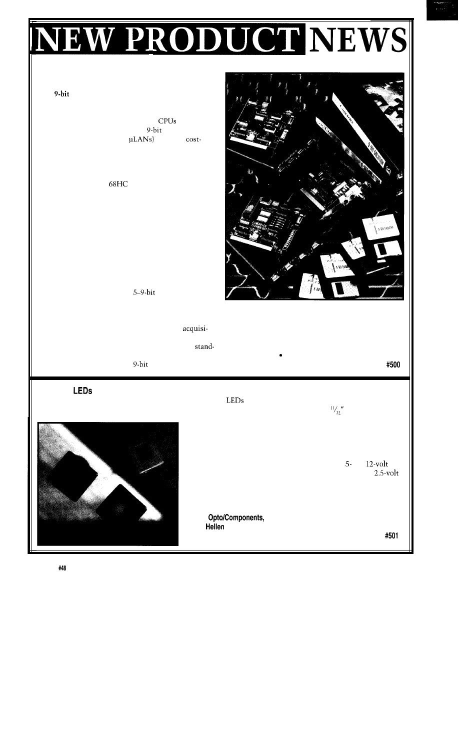
PC-LESS MICROCONTROLLER NETWORK
Cimetrics Technology has announced two additions
to its
Solution line, an array of software/hardware
packages which enable designers of embedded systems to
network their embedded Intel, Motorola, or Zilog
microcontrollers. By linking up to 250
using each
processor’s built-in serial port, the
Solution
microcontroller networks (or
provide a
competitive, development-sensitive system for adding
monitoring, diagnostics, control, or data acquisition
capabilities to CPU-based products or subsystems.
The Microcontroller Master Software for Intel
80C 186 and Motorola
11 enables the system
designer to create a network composed entirely of
embedded microcontrollers; a PC need not be a compo-
nent of the completed network. This type of “PC-less”
embedded controller network is particularly well-suited
to use in distributed control and data acquisition
systems where polling must occur automatically and a
user interface is not required. C language source code is
provided for easy modification and maintainability.
The NBS-10 Device Driver for Windows NT is
designed for RS-485 and RS-422 applications. This driver,
which enables PCs to participate in a microcontroller
network, offers programmable
asynchronous
character format at 288,000 bps. The multitasking assets
of Windows NT and the above hardware and software
consisting of the Network Software, Network Monitor
provide an ideal platform for the designer who wishes to
software, and two NBS-10 interface cards, is available for
analyze and process data concurrent with data
$1995.
tion.
The Microcontroller Master sells for $1500 as
Cimetrics Technology
alone software and the NBS-10 device drive sells for $500
120 West State St. Ithaca, NY 14850
plus $10 per CPU. A complete
Solution Package,
(607) 273-5715
l
Fax: (607) 273-5712
SQUARE
A way to efficiently mount contemporary-styled square
in inexpensive round holes has been provided in a
new style of front-panel LED indicators from Lumex. The SSI-LXH55 series fits into standard
round holes,
while the outside dimensions are a perfectly square 5 x 5 mm (0.2” x
0.2”) for the lighted area and 10 x 10 mm (0.4” x 0.4”) for the sur-
rounding black bezel.
Five color choices include blue, green, yellow, amber, and red,
with bicolors available as specials. Light intensity varies from 14 to
50 mcd depending on color. Other options include and
designs with an integral current-limiting resistor chip and a
style without current protection. Terminations are 0.020” square, 1”
long tin-dipped pins or 26 AWG insulated leads of any length. Prices
range from $0.25 to $0.75 depending on model.
Lumex
Inc.
292 E.
Rd.
l
Palatine, IL 60067
(708) 359-2790
l
Fax: (800) 944-2790
8
Issue July
1994
The Computer Applications Journal
FILTER
A rugged, RS-232 programmable, low-pass filter unit targeted for use
in front of any A/D converter in avionics, automotive, and other indus-
trial data acquisition systems has been introduced by Alligator
nologies. The AAF-HESP is an eight-channel board that features a
software-selectable cutoff frequency range, DC accuracy, 0.5
degree phase matching between channel, and a five-pole
worth filter with a maximally flat
and low phase lag.
Capable of withstanding high vibrations and extreme tempera-
tures, the AAF-HE8P filter is ideal for such applications as
airborne instrumentation and control, on-ground vehicle or
engine testing, shock and vibration measurement, ultrasonics,
sonar and acoustic analysis, and robotics.
Designed to ensure data integrity, the AAF-HESP allows valid input
signals to pass while removing undesired signals with frequency components above
one-half the sampling rate of the A/D converter. (Aliasing is a direct result of foldover. If the
sampling rate is set at 200 Hz, then frequency components at or higher than 100 Hz will fold over into
the lower frequency spectrum and appear as
events that may not be distinguishable from valid sampled
data. Using an antialiasing filter with sharp attenuation eliminates the need to oversample the input signal.)
The AAF-HESP filter is programmable through an RS-232 port, allowing users to control the cutoff frequency of
up to 16 units with a single RS-232 link. The frequency setting of the filter remains through power on-off cycles until
changed by new programming. One three-byte communications sequence is sent at standard protocol and controls
the cutoff frequency for all eight channels. Complete verification of operation is returned to the host to aid in system
diagnosis.
Each AAF-HESP has one
power and serial interface connector as well as two 9-pin I/O connectors. The
AAF-HESP Antialiasing Filter configured with eight filtered channels sells for $3950. Substantial discounts are
available for
system integrators, and multiple end users.
Alligator Technologies
2900 Bristol St., Ste. E-101
l
Costa Mesa, CA 92626-7906
l
(714) 850-9984
l
Fax: (714) 850-9987
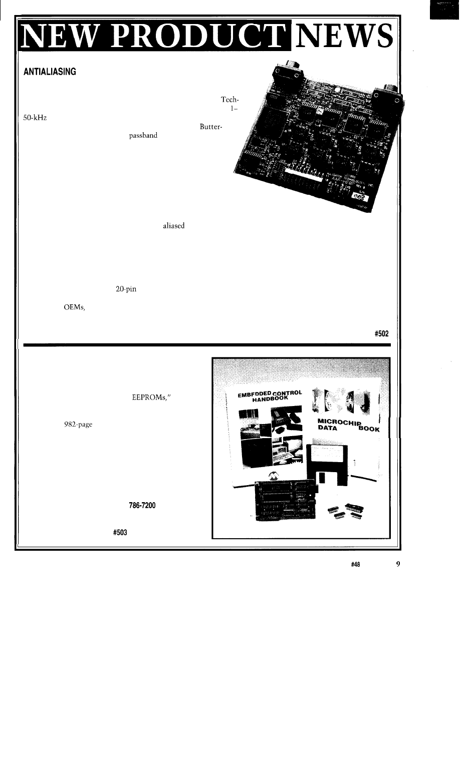
EMBEDDED
CONTROL
HANDBOOK
Microchip Technol-
ogy has announced the
availability of its latest
Embedded Control
Handbook,
a
technical reference tool
created for systems and
applications designers
using PIC S-bit micro-
controllers, and specialty
nonvolatile memory
products.
The handbook
included more than 50
application notes and
pieces of software
written for specific
embedded control applica-
tions such as “Servo
Control of a DC Brush
Motor,” “Logic-powered
Serial
and
“LCD Controllers.” Addi-
tional highlights include
schematic and timing
diagrams, math routines,
and associated figures for
comprehensive application
support.
Microchip Technology, Inc.
2355 West Chandler Blvd.
Chandler, AZ 85224-6199
(602)
Fax: (602) 899-9210
The Computer Applications Journal
Issue
July 1994
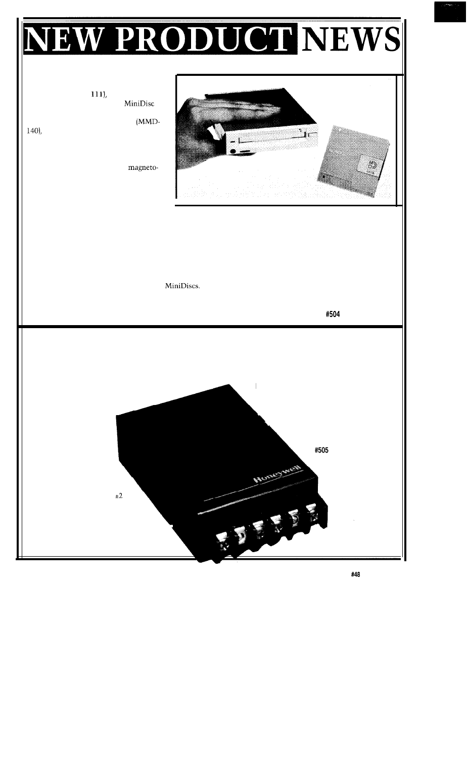
MD DATA DRIVE AND MEDIA
S o n y h a s i n t r o d u c e d t h e f i r s t
MD
DATA drive (MDM
a rewritable
storage device based on Sony’s
personal audio technology. When combined
with rewritable MD DATA media
the format provides exceptional
flexibility for data management, storage,
and distribution.
The MD DATA drive and media
provides 140 MB of storage on a
optical disc measuring 2.5” in diameter.
The MD DATA drive accepts rewritable,
read-only, and hybrid (with both read-only
and rewritable sections) media. With the
ability to handle various types of digital
information, MD DATA is ideal for applications such as personal backup, interactive software, electronic publishing,
and easy transportation of large files.
In contrast to conventional magneto-optical drives, MD DATA drives rewrite discs in a single pass. Size, cost,
and power consumption are thereby reduced, making MD DATA ideal for portable applications. Discs can also be
rewritten with virtually no loss of data integrity.
A new universal file system allows MD DATA discs to be used interchangeably between computers with the
currently most popular operating systems. Besides computer applications, MD DATA drives can also play prere-
corded music titles and user-recorded audio
Sony Electronics
3300 Zanker Rd.
l
San Jose, CA 95134
l
(800) 352-7669
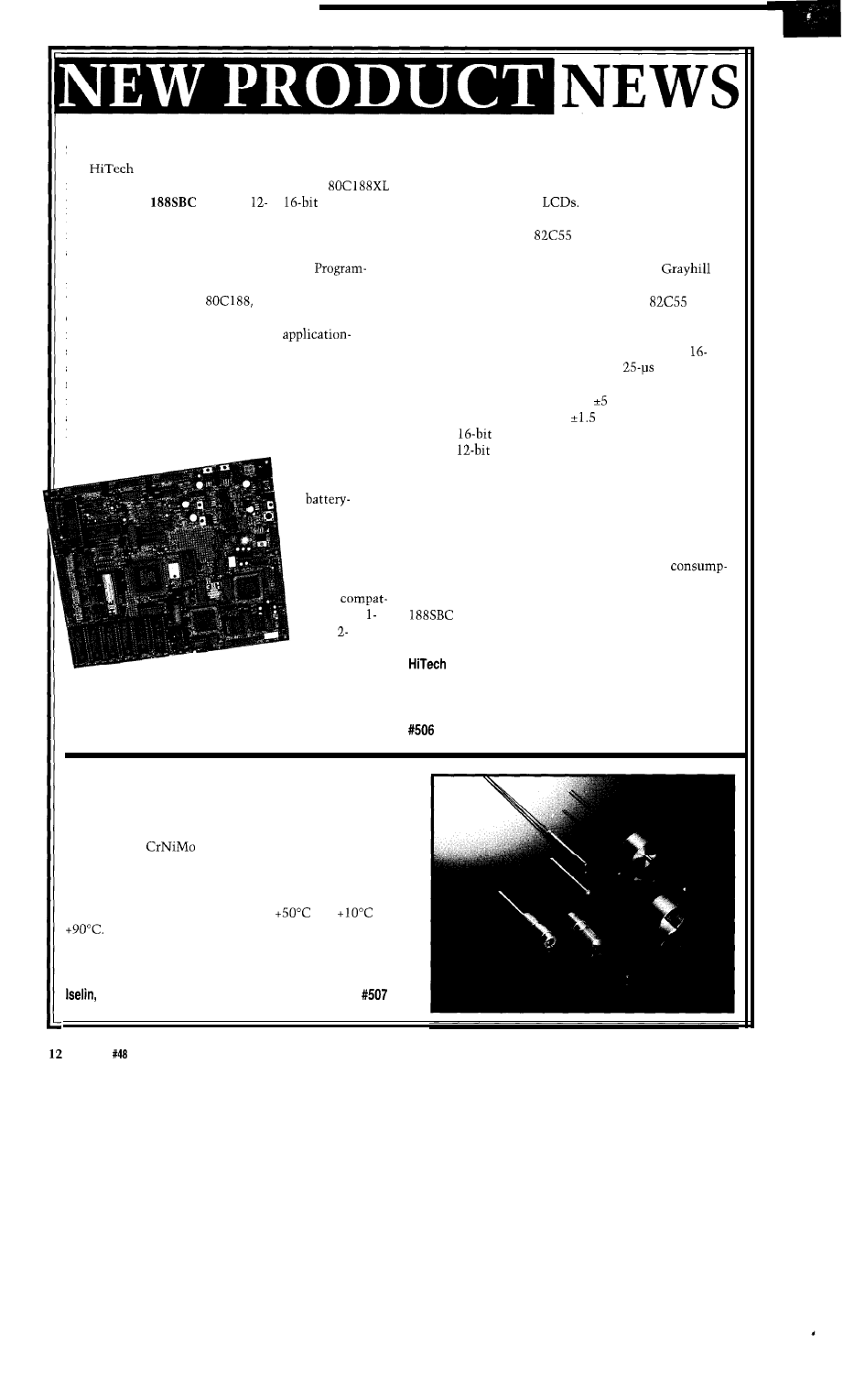
DIGITAL MAGNETOMETER
A smart magnetometer
has been introduced by the
Solid State Electronics Center of Honeywell. The unit
has applications in compassing, attitude positioning,
traffic and vehicle detection, remote vehicle
The unit is based on a magnetoresistive thin film
permalloy process. The on-board microcontroller handles
the magnetic sensing, first-order temperature correction,
and all output communications.
monitoring (yaw/roll/pitch),
security systems, and
process control.
The magnetometer
uses a microcontroller
to produce a three-axis
digital output device
that features high
sensitivity, low power
consumption, ease of
use, and affordability. The
smart digital magnetometer
has a measurement range of
gauss with 1% accuracy and a
sensitivity level of 0.5 milligauss.
The device interfaces to RS-485 for
.
multiport bus transmission and can be
easily interfaced to an RS-232 port.
Honeywell, Inc.
Solid State Electronics Center
12001 State Highway 55
Plymouth, MN 55441
(612) 954-2692
Fax: (612) 954-2051
The Computer Applications Journal
Issue
July
1994
11
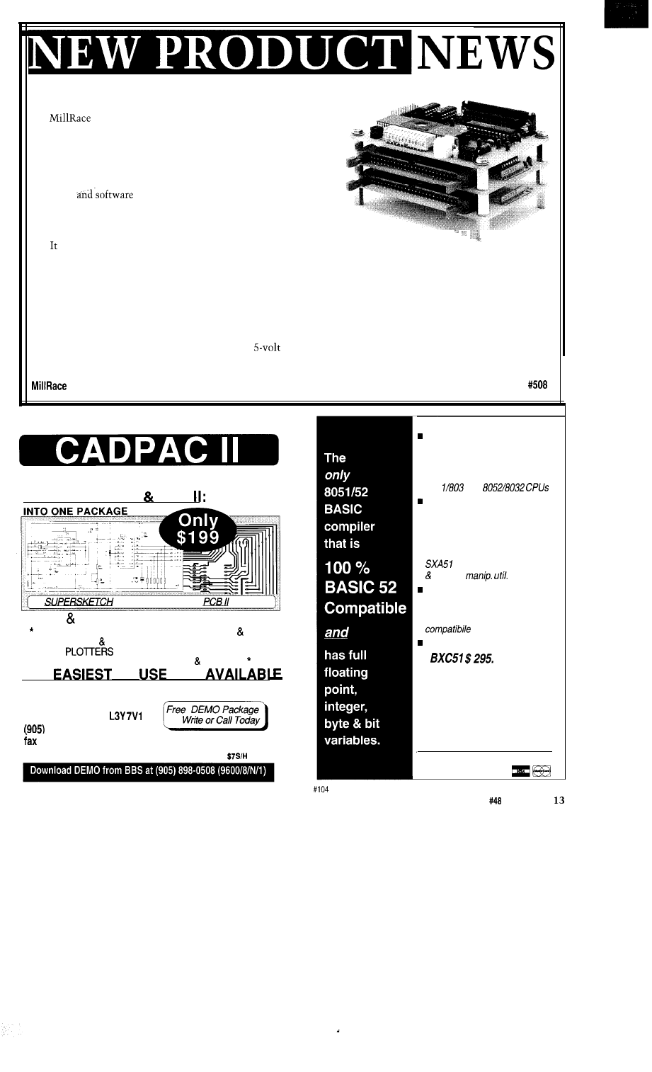
SINGLE-BOARD COMPUTER
from 50 to 38.41~ bps. The bidirectional parallel port is
Equipment Corporation has announced a
configured as a Centronics-compatible interface.
new single-board computer based on the Intel
Other digital interfaces include a direct interface to
processor. The
provides
or
A/D and
character and graphics
The interface is compatible
D/A converters, serial ports, a parallel port, opto rack
with the Hitachi 44780, Toshiba T6964, SMOS 1330, and
interface, LCD and keyboard interfaces, real-time clock,
other controllers. One
programmable peripheral
and a PC/ 104 expansion bus.
interface chip provides a direct interface to optical
A unique feature of the board is a Field
isolation/relay racks similar to Opto-22 and
mable Gate Array, available for user customization.
products. LED indication of output and input states is
When configured by the
the gate array can take
available on all 24 control lines. A second
on the personality of any digital circuit the user may
provides an interface to additional external I/O such as a
require for a special interface or other
keyboard matrix.
specific circuit. The Xilinx 3000 series FPGA socket
The analog portion of the board consists of a
accepts the XC3030 through XC3090 parts containing
channel, 12-bit A/D converter with a
conversion
from 100 to 320 Configurable Logic Blocks for a wide
time. A common low-pass antialiasing filter is provided
range of flexibility. A breadboard area on the board
and input voltage levels may be V or O-10 V. The
allows prototyping of level converter circuits for the
converter is specified with a
LSB accuracy, and an
FPGA.
optional
converter is available. The D/A converter
The 188SBC is
also has
resolution. A SMP-08 sample-and-hold
complemented by
multiplexer creates eight D/A output channels for the
up to 5 12K bytes
converter.
of
Power to the system is provided by an on-board
backed, fully
switching regulator. This regulator supplies quiet power
static RAM.
to the analog circuits via isolated power and ground
Two additional
layers on the circuit board. Input to the regulator can
sockets are
range from 12 V to 20 V AC or DC and power
provided for
tion is typically 350 milliamps, fully loaded. A
code,
nonmaskable Power-Fail interrupt is provided. The
ible with
price starts at $299 and tops out at under $750
and
for a fully loaded board.
megabit
EPROMs or flash
Equipment Corp.
memory. On-board flash programming
9400 Activity Rd.
l
San Diego, CA 92126
is provided.
(619) 566-l 892
l
Fax: (619) 530-l 458
Two serial ports are available, each selectable as
either RS-232 or RS-485. Data rates are programmable
FLUID-LEVEL SENSORS
A new line of metal-encapsulated fluid-level sensors for
monitoring temperature has been announced by the Special
Products Division of Siemens Components. Housed in a
noncorroding
steel housing, the sensors can be used
in water, oil, gasoline, and detergent solutions. As such, they
are ideal for chemical processing and petroleum refining
applications. The fluid-level sensors are available in a choice
of two temperature ranges: -25°C to
and
to
Siemens Components, Inc.
186 Wood Ave. South
NJ 08830
l
(908) 603-5919
Issue
July 1994
The Computer Applications Journal
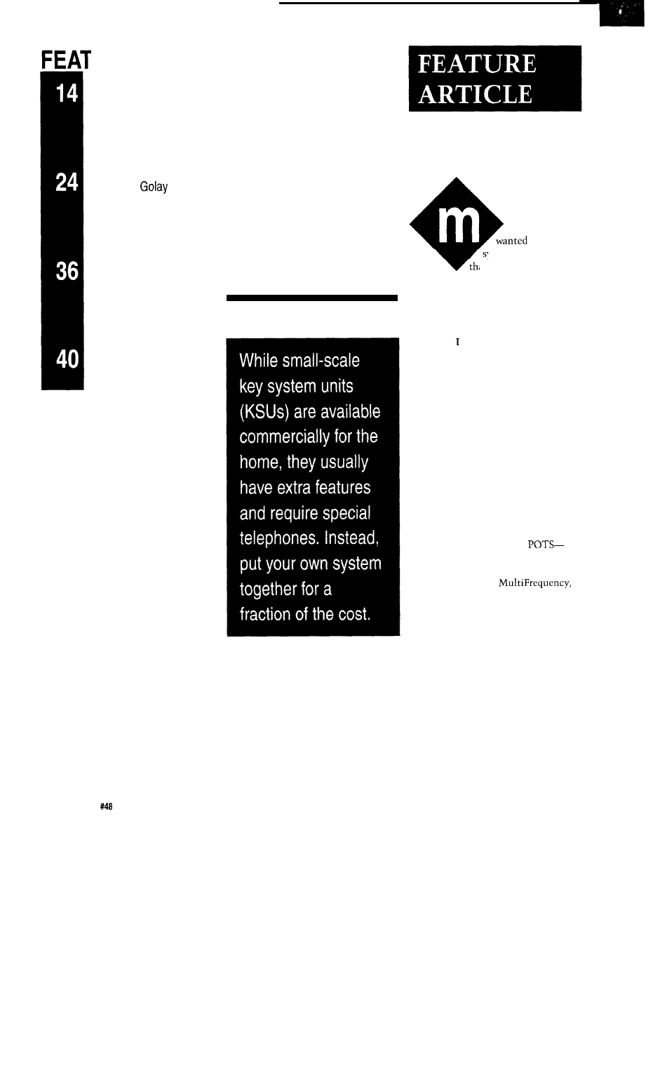
DIGITAL INTERFACE DEVICE
Software has announced a new concept that effectively
locates a computer interface card in a custom hardware design. The
compact design minimizes cables and increases I/O bits up to 320
lines. A high level of I/O control is available from any computer by
means of a standard RS-232 connection.
The I/O Stack provides a computer interface with a minimum of
hardware
design. The CPU and functional boards are
stacked one on top of another to provide a compact unit to be mounted
inside the user’s application hardware. The I/O Stack is ideal for rapid
prototyping of a design or for use in one-of-a-kind applications.
consists of a microprocessor board and one or more (up to a maximum of 8)
TTL I/O boards. The microprocessor board is the stack controller and is interfaced to the user’s computer through an
RS-232 interface. Data rates from 150 bps to 19.2 kbps can be accommodated.
Each TTL I/O board contains 5 bytes (40 bits) of I/O lines. Each byte is either all input or output, so a TTL I/O
board may contain any combination of input or output byte configurations. Input or output can be at the bit, byte, or
word level. Word I/O can optionally use a 2-wire handshaking method to pace data flow.
The I/O Stack is ready to run-there is no embedded code to write. Digital control is accomplished with a simple
high-level ASCII command set. Numeric parameters can be specified in decimal, hex, octal, or binary formats. The
I/O Stack provides standard TTL interfacing; only
DC power is required. The I/O Stack microprocessor board
sells for $495 and each TTL I/O board, in any configuration, sells for $295.
Software
l
828 Manhattan Beach Blvd.
l
Manhattan Beach, CA 90266
l
(310) 546-6737
TWO PROGRAMS FOR ONE LOW PRICE!!
SUPFRSKETCH PCB
INTEGRATED
PCB II SUPERSKETCH features:
MOUSE DRIVEN *SUPPORTS CGA, EGA, VGA SVGA,
l
OUTPUT TO 9 24 PIN PRINTERS, HP LASERJET&
HPGL
l
OUTPUT TO DTP PACKAGES
l
* PCB II ALSO HAS GERBER OUTPUT VIEWING.
THF
TO
CAD
R4 SYSTEMS Inc.
1111 Davis Drive, Suite 30-332
Newmarket, Ontario
898-0665
(605) 898-0683
ALL PRICES ARE IN US FUNDS, PLEASE INCLUDE
Memory mapped variables
n
In-line assembly language
option
n
Compile time switch to select
805
1 or
Compatible with any RAM
or ROM memory mapping
n
Runs up to 50 times faster than
the MCS BASIC-52 interpreter.
n
Includes Binary Technology’s
cross-assembler
hex file
Extensive documentation
n
Tutorial included
n
Runs on IBM-PC/XT or
Compatible with all 8051 variants
n
508-369-9556
FAX 508-369-9549
q
Binary Technology, Inc.
P.O. Box 541
l
Carlisle, MA 01741
The Computer Applications Journal
Issue
July
1994
‘URES
The Personal PBX
Using the
Error Detection and
Correction Code
The Great Encryption
Debate
Take a Bus to the
Nearest Star
The
Personal
PBX
Richard Newman
any years ago, I
a telephone
ystem in my home
at would let all the
devices that use a telephone line share
the two I had. Looking at commercial
phone systems, I found they were all
too expensive and had features meant
for a business environment rather than
the home. decided to build one, and
the first version worked great, using
five relays for every phone. The
version of the project I’m presenting
here came along about 10 years later
and uses only one relay per phone.
The small switching system, or
Personal PBX, presented here is
actually the prototype of a larger
system that is used commercially in
the private operator service industry to
provide dial tone to hotels, dorms, and
institutional environments.
In this article, I will describe how
to provide basic telephone service to
single-line telephones (called “2500
sets,” which are served by
Plain Old Telephone Service). The
project will provide dial tone, receive
DTMF [Dual Tone,
often called Touch Tone) signals, ring
the phones, and set up conversations
between two or more sets.
I’ll also leave open the possibility
of adding more features, an interface to
the public switched network, and an
interface to a PC serial port for remote
control and voice response.
TELEPHONE BASICS
Your telephones at home connect
to the telephone company’s central
office (CO) by way of two wires called
the wire pair, with one wire called tip
and the other ring. Curiously, these
14
Issue
July 1994
The Computer Applications Journal
ROM
32K
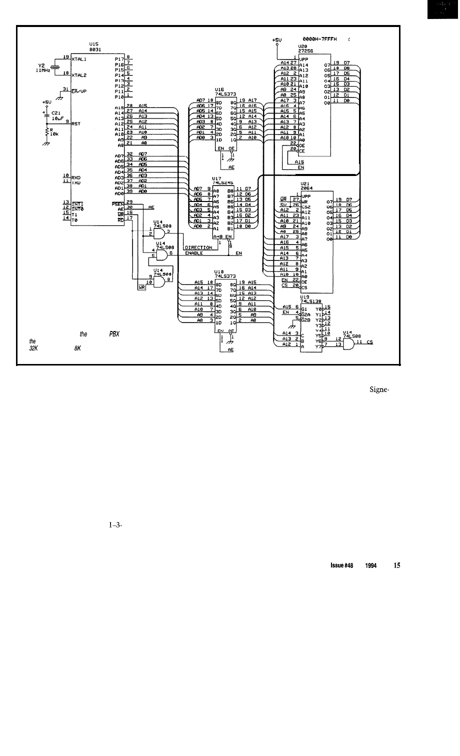
Figure la--The core of Personal
is based on
popular 8031 and includes bus buffering, decoding,
of EPROM, and
of RAM.
names date back to the time when
human switchboard operators manu-
ally connected calls with patch cords.
Each cord had a jack similar to that
found on today’s headphone cords, and
that jack had a tip and a ring.
When the phone is off-hook, the
wires carry about 20 milliamps of
current from the CO through the
telephone set and back to the CO. Tip
is closest to earth ground and ring,
when measured from the telephone
end, has about -48 volts DC on it.
When the phone is on-hook, no
current flows. When someone calls
your house, the CO places 90-130
volts AC on your wire pair in
second bursts to make the ringer in
your phone sound. Lifting the receiver
allows current to flow and a conversa-
tion can take place.
Because of the relatively high
voltages used by the telephone
network, special interfaces must be
used to control the telephone lines and
set up conversations between them.
The system I present here-the
Personal PBX-does just that: illus-
trates interfaces for connecting
telephone equipment to a controlling
microprocessor.
THE HARDWARE
There are six major hardware
sections to the Personal PBX: CPU,
power supply, subscriber line interface
circuit (SLIC), ring generator, common
control, and switch matrix.
CPU
The project is based on a
tics/Philips 805 1 microprocessor with
32K of EPROM and 8K of static
battery-backed RAM (see Figure la).
The EPROM contains the core code
that controls the hardware, and the
RAM contains the “translation”
information that specifies the tele-
phone number of each telephone set,
the “class of service” that specifies
what the phone can do, and the “class
of restriction,” which specifies where
the phone can call (if it could call the
real world, anyway).
Although I show interfaces for
only one telephone set in the sche-
matic, you can add as many interfaces
as you like for as many phones as you
The Computer Applications Journal
July
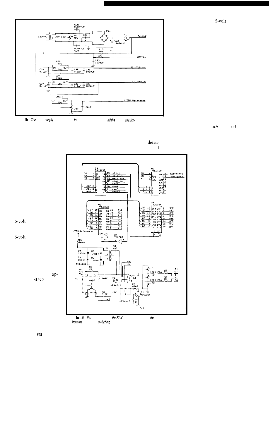
providing service for
them (Figure lb). It
consists of a transformer
and rectifier that
provides 24-40 volts
unfiltered DC, a filter
arrangement that
provides 24-40 volts of
filtered DC (called the
“talk supply”), a positive
regulator (or two)
that powers all of the
digital logic, and another
regulator that
powers all of the analog
parts including the
switch matrix and
common controls. A
variable floating regula-
tor provides a virtual
ground for all of the
amps and
that
actually sits at about
1.75 volts.
The analog portions
of the system require
very quiet DC supplies
or the noise will be
coupled into the conver-
sation. Even though
Figure
is responsibility of
to
electrically isolate high-voltage telephone
loop
low-voltage
matrix,
Figure
power
is large enough service 32 phones and control
need [as long as you don’t run out of
people talking on the telephone sets
I/O space or CPU time).
cannot hear the noise, the DTMF
POWER SUPPLY
receivers can, and a noisy power
supply will increase the signal
The power supply for the system
tion time considerably. To this end,
is large enough to service
32 phones and all of the
common control
provide a separate analog
supply
that powers anything relating to audio,
including op-amps, dial tone genera-
tors, DTMF receivers, and the virtual
ground regulator.
The virtual ground is necessary
because I am using a single supply for
all of the audio paths between the
system’s subcomponents. Without a
virtual ground sitting somewhere
between real ground and the supply
voltage, the AC waveforms would go
below ground on the negative swing of
the signal, causing some components
to misbehave. Since all of the wave-
forms are referenced to the 1.75volt
virtual ground, they end up swinging
from about 0.25 V to about 3.25 V.
The 24 volts filtered DC is used to
provide power to all of the telephone
sets, which need 2030
in the
hook condition. A filtered supply is
required to prevent the AC line hum
from being coupled into the conversa-
tion. I chose a filtering arrangement
with a power resistor
because it is less costly
than a large inductive
filter even though it
dissipates lots of heat.
The unfiltered 24 V
is used to power anything
that is noisy, including
the relays and the ring
generator. When the ring
generator is used, a large
DC reserve from the filter
cap is necessary to create
a field of sufficient
strength in the ring
generator coil to make an
AC waveform ring the
bell in a telephone set.
SUBSCRIBER LINE
INTERFACE CIRCUIT
It
is the responsibil-
ity of the SLIC (Figure lc)
to electrically isolate the
high-voltage telephone
loop that extends from
the telephone equipment
to the telephone set from
the low-voltage and
fragile switching matrix.
Additional duties include
indicating when the
telephone is off-hook, and
16
Issue
July 1994
The Computer Applications Journal
switching high voltage onto the line to
ring the telephone set.
and may extend from several hundred
to several thousand feet. It is a
wire balanced line, that is, you may
not bridge the wires in the field to
share a common ground between two
telephone sets.
The SLIC I present here provides a
nonstandard interface: the loop current
may vary and the loop impedance does
not reflect 600-900 ohms which is
desirable in the telephone industry.
However, this SLIC is inexpensive and
is very workable for the Personal PBX.
The line current to the telephone
set is provided by two
resistors: one to ground and the other
to the 24-volt line. These two resistors
provide subscriber loop tip and ring.
Tip and ring are then bridged onto
the primary of a
audio
matching transformer through a 1
nonpolarized capacitor to block the
DC loop current. When an audio signal
from an off-hook telephone set appears
at tip and ring, a facsimile of it will
also appear at the secondary of the
audio transformer.
One terminal of the audio trans-
former is connected to the analog
virtual ground, so any waveform
coupled to the secondary will be riding
on this 1.75volt DC carrier.
On the secondary are two sets of
diodes connected so the AC
waveform never exceeds about 3 volts
peak-to-peak. This provides protection
after the operation of the ring relay,
which may otherwise couple a
voltage spike onto the secondary and
destroy the switch matrix.
When the telephone sets user lifts
the receiver, the telephone allows
current to flow, which in turn turns on
the optocoupler in the SLIC to inform
the CPU that the phone is off-hook.
When the CPU needs to ring the
telephone, it operates the associated
ringing relay on the SLIC and activates
the common ring generator, which
generates 90 VAC at 20 Hz. After
providing one ring burst, the CPU
releases the ring relay, returning the
telephone to the audio coupling and
current detection circuitry of the SLIC.
OMRON
U 2 4
R24
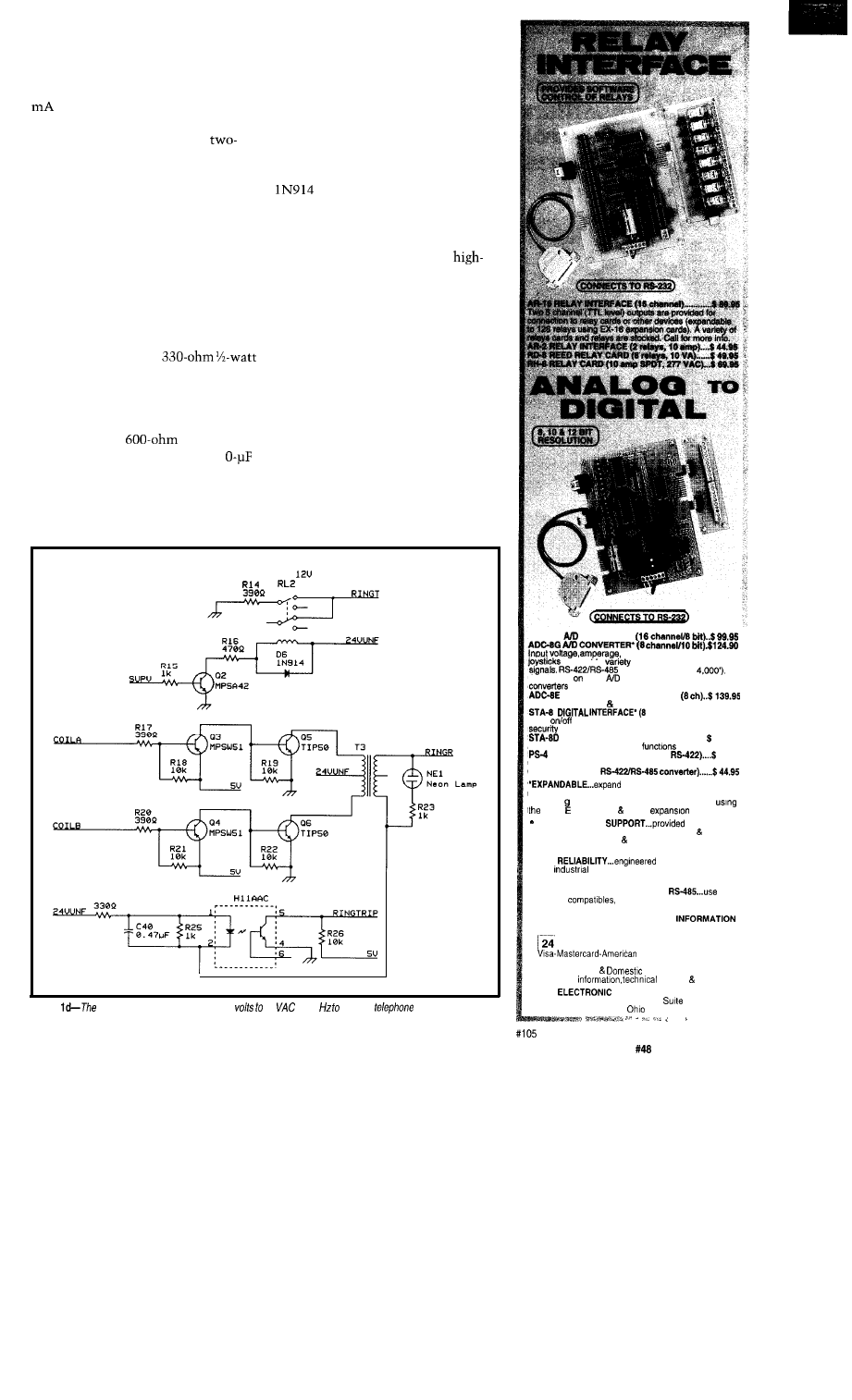
Figure
ring
generator circuit converts 24
90
at 20 ring fhe
sets.
ADC-16
CONVERTER*
pressure, energy usage,
and a wide
of other types of analog
available (lengths to
Call for info
other
configurations and 12 bit
(terminal block and cable sold separately).
TEMPERATURE INTERFACE’
Includes term. block 8 temp. sensors (-40’ to 146’ F).
channel) . . . . . . . . . $99.95
Input
status of relays, switches, HVAC equipment,
devices, smoke detectors, and other devices.
TOUCH TONE INTERFACE’................ 134.90
Allows callers to select control
from any phone.
PORT SELECTOR (4 channels
79.95
Converts an RS-232 port into 4 selectable W-422 ports.
CO-485 (RS-232 to
your interface to control and
monitor up to 512 relays, up to 576 digital inputs, up to
128 anal0
PS-4,
inputs or up to 128 temperature inputs
X-16. ST-32 AD-16
cards.
FULL TECHNICAL
over the
telephone by our staff. Technical reference disk
including test software programming examples in
Basic, C and assembly are provided with each order.
. HIGH
for continuous 24
hour
applications with 10 years of proven
performance in the energy management field.
‘CONNECTS TO RS-232, RS-422 or
with
IBM and
Mac and most computers. All
standard baud rates and protocols (50 to 19,200 baud)
Use our 800 number to order FREE
PACKET. Technical information (614) 464.4470.
HOUR ORDER LINE (800) 842-7714
E x p r e s s - C O D
International
FAX (614) 464-9656
Use for
support orders.
ENERGY CONTROL, INC.
380 South Fifth Street,
604
Columbus,
43215.5436
The Computer Applications Journal
Issue
July 1994
1 7
750
Ave., Sunnyvale, CA 94086
Tel: (408) 245-6678
(408) 245-8268
RING GENERATOR
The ring generator (Figure Id) is
simply a small inverter that is used to
step up the 24-volt DC unfiltered
supply to 90 volts AC with a frequency
that is controlled by the CPU. The
frequency is normally 20 Hz to ring
the telephone sets, however some
telephone sets have message waiting
lights that respond to a
or
signal without ringing the bell, so the
computer has the option of generating
these alternate frequencies.
The ring generator circuit also has
a loop current detector so if the
computer is ringing the telephone set
and the user picks up the receiver
during a ring, the computer is notified
to immediately stop the ring and
connect the party to the caller. This
“in-cycle” answer of a telephone is
called ring trip.
COMMON CONTROL
The system’s common control
(Figure le) includes two dial tone
generators and DTMF receivers that
can be connected to any of the tele-
phone sets through the switch matrix
under the CPU’s control whenever a
telephone set demands service.
The dial tone generator chip is
available from only one source:
Teltone. Requiring just a
crystal to operate, it generates all the
industry-standard call progress tones
including dial tone, ringback, busy,
reorder, several intercept tones, a
DTMF
(but no other DTMF
signals), and others. Its downside is it’s
pricey, single
and is not
directly CPU bus compatible. If you
care to, you may replace this device
with a dedicated dial-tone circuit
consisting of a few op-amps generating
a 400-Hz sine wave and gate that into
the point where the Teltone generator
would have gone.
The dial tone generators are
buffered through an op-amp and then
coupled to the matrix through a
nonpolarized capacitor. The input to
the DTMF receiver is connected to a
rail in the switch matrix along with
the output of the dial tone generator.
The
DTMF receiver also
has call progress detection and a
in DTMF generator. This device is
very similar to the
which
has been used in several projects in the
Computer Applications
Requiring only a
color
burst crystal to operate and a single
volt supply, it is directly compatible
with the CPU bus, but requires a
separate I/O port to sense the “digit
valid” and “call progress” bits. some
applications, these might instead go to
the CPU interrupt structure.
The dial tone
receiver combinations are assigned on
an as-needed basis. Once used, they are
disconnected and may be used by
another party. A conversation in
progress between two telephone sets
does not need a generator/receiver.
Only two persons may be dialing at
any given time, but there can be up to
eight separate conversations happening
at once.
The switch matrix is responsible
for getting the analog signal from one
SWITCH MATRIX
place to another (Figure
The device
used in the Personal PBX project has
96 analog switches in an array of 12 x
8. Called the M093, it is available from
a variety of manufacturers including
Mite1 and SGS-Thompson. The MO93
is powered from the
analog
supply and will pass signals from any
input to any output in either direction
with only 75 ohms of resistance
through any one crosspoint.
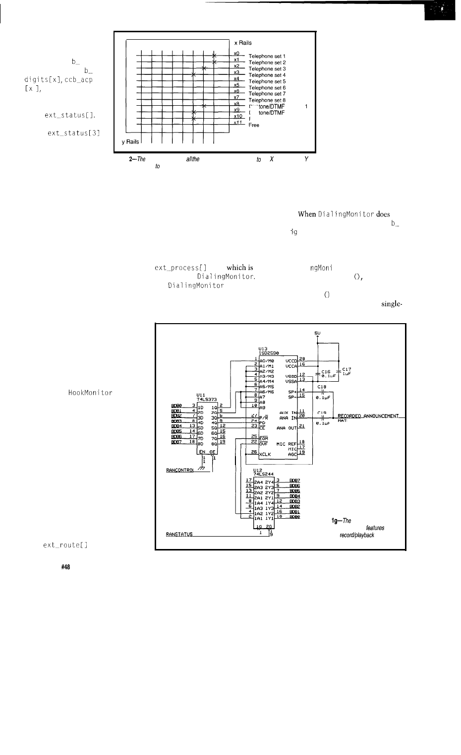
The switch matrix is controlled by
the microprocessor and has all of the
telephone sets connected to a different
X rail in the device. The Y rails in the
device are the speech paths and may be
daisy-chained to multiple switch
matrix chips to form a larger switch
platform. To connect two telephones
together, you close the X rail of the
telephone sets on the same Y rail and
the sets are then electrically connected
in a conversation (see Figure 2).
One oddity of the MO93 device is
that in addressing the X side of the
crosspoints, it skips addresses 6 and 7.
As a result, when referring to
you
use address 0, but when referring to
X6, you use address 8. This oddity is
handled by the low-level library
routines and is transparent when
writing software for the switch.
18
Issue
July 1994
The Computer Applications Journal
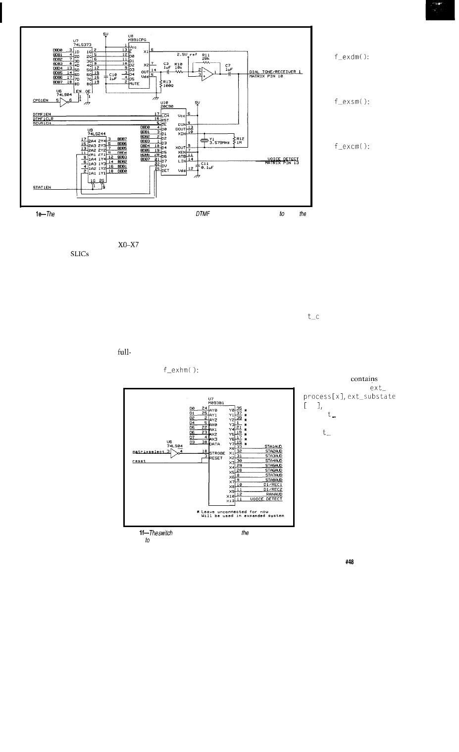
Figure
system’s common control
includes two dial tone generators and
receivers that can be connected any of
telephone sets.
In this project, I will use only one
MO93 for now. Each of the rails
connects to the
1-8,
respec-
tively. X8 and X9 are connected to dial
tone generator/DTMF receiver combi-
nations. X10 is connected to a speech
playback device for recorded an-
nouncements, and Xl 1 is left available
for experimentation.
the message to be played without
unexpected results.
There is only one DAST in the
system, but like all the other common
peripherals here, it is assigned to the
call only when it’s being used and then
is released to service other callers.
RECORDEDANNOUNCEMENT
An optional extra feature I haven’t
mentioned up to this point is a
recorded announcement. In the
blown commercial version of this
switch, I use this feature to prompt the
caller for a calling card number and
keep them informed of the
progress of the call. I selected
the easy-to-use (though
currently impossible to get)
DAST device manufactured
by Integrated Storage Devices.
The code that controls the
Personal PBX is a large state machine
that has been broken down into
smaller C functions. The major
functions include:
The hook switch
monitor. Waits for a user to lift a
The ISD2590 features 90
seconds of record/playback
that, when accessed sequen-
tially, requires only five
control lines and two status
lines. One nice feature of
using the sequential message
queuing mode is that very
little CPU overhead is
required to keep track of what
this device is doing, so we can
take our time in setting up
When the dispatcher detects that
it is time for a phone to get a share of
the CPU time, it sets a global variable
called e x
h e
c
k that equals the port
being serviced and is also the index to
the arrays that hold the state the
telephone set is in.
Each phone in the system has
memory variables in an array assigned
to it. If there are eight phones in the
system, then the array
eight
elements. The arrays
x and all others beginning
with ex
are permanently
assigned to the port. Normally
the ex variables are indexed
with a global variable called
dispatch-process. When
port 3, for example, has a share
of the CPU time, dispatch__
process equals3.
Figure
matrix is responsible for getting analog signal from
one place another.
THE SOFTWARE
The ma i n procedure
contains the startup
code. When the system is
powered up or the processor is reset,
the startup code immediately turns off
the ringing generator coils, resets all
phone, then sets up the
phone to be serviced by
other routines.
The
dialing monitor. Every-
thing having to do with
dialing and call setup is
handled here.
The
extension signaling
monitor. Ringing the
telephone sets is this
routine’s job.
The
conversation monitor.
During the call, this
routine is in control, but
its biggest job is cleanup
when the call is finished.
relays to the off state, and clears the
state machine variables to a known
state.
There are other variables
that are also arrays, but they
are not permanently assigned
to any one phone. Instead, they
are assigned to a phone when
that phone goes off-hook and
they stay assigned during the
The Computer Applications Journal
issue
July 1994
19
entire call. These are
called
call control blocks
and are sets of arrays
indicated by
CC
before
their name (e.g., cc
etc.). Call control
blocks are assigned to the
phones by a port variable
called
If
CCB 1 is assigned to port
3,then
will equal
1.
Because each phone
has a different index to
the same set of variables,
Dial
receiver
Dial
receiver 2
Recorded announcement
Figure
switch matrix
has telephone sets connected fhe rails while the
rails are connected speech paths.
this state machine could be said to be
servicing different
contexts
each time
it is dispatched. Each context has very
different concurrently executing
functions. One phone might be dialing
while another is ringing, but they are
being serviced by the same software.
You can expand the number of ports
being serviced by making the array
that holds the common variables
larger.
SYSTEM OPERATION
The software attempts to emulate
a central office, so it is transparent to a
user dialing from a telephone con-
nected to it. It might be helpful to fol-
low a call through the state machine.
First, the source and destination
telephone ports are idle. They are both
executing state 0, which is looking at
the current detector and waiting for it
to detect off-hook.
When the person on port 0 picks
up thephone,
first
locates a free call control block that
will be used to store information about
the call in progress. If HookMoni tor
cannot find a free call control block, it
simply does nothing and falls through
to the end of the code block. The
dispatcher then goes on to service all
the other phones in the system. When
it gets back around to port 0 again, it
starts the same process of looking for a
call control block. Ideally, it will
always find a free call control block. In
the worst case, it would find one when
someone else hangs up and their block
is freed.
Next, HookMoni tor clears the
port’s
variable. This
allows any process to see that the call
has yet to go somewhere.
Thefinalsteps HookMoni tor
takes are to locate a free dial tone
sender, DTMF receiver, and speech
path for the conversation to take place
on. Once all of the above is done, the
user hears dial tone from the earpiece
of his telephone set. HookMoni tor
now sets the extension state variable
to33,
the
entrystateof
decrementsthe
extension timer, which gives the user
predetermined period of
time, a reorder tone [fast
busy) is sent to the port.
When the reorder tone is
sent, the same timer is
loaded with a finite
amount of time again.
When it expires a second
time, all of the resources
assigned to the call are
freed, including the call
control block and speech
path. There is now a
phone off-hook, but no
hardware assigned to it,
so a
lockout condition,
or
state 36, is assigned to it. This state
does nothing more than wait for the
phone to go on-hook, which will start
the off-hook monitor all over again.
detect a digit, it is stored in the cc
d i t.
s
area and the routing tables are
searched for a match. In my example,
let’s say the user dials a 4 first. After
the 4 button is pressed and released,
Dial i
tor will store the digit
and then call se a r c h which will
look in a single-digit table. In this case,
s e
a r c h
won’t find a match for the 4
a finite amount of time to dial the first
because there is nothing in the
digit. If nothing is dialed within this
digit table to find. When the user then
RIX PIN 12
Figure
optional recorded
announcement support
90
seconds of
capability.
20
Issue
July
1994
The Computer Applications Journal
dials a
3 as the second digit, se a r c h
will now look in a double-digit table,
and will find a match for the 4 as the
first digit and the 3 as the second digit.
When this match is found, e a r c h
will update
to
be the
action stored with the found digits. In
our case, the action is to send the call
to another port on the system.
When
that
the time for a digit to be dialed has
expired, it will look to see if a route
has been chosen and, if so, whether it
is a call to another port on this system.
There is a reason I wait for the
interdigit time to expire rather than
just place the call as soon as I find a
match. One of the original system
design goals was to make this small
system work transparently to its users,
but still provide all of the features of a
private branch exchange. In order to do
this, I wanted to allow extension
numbers to be able to conflict with
local exchange numbers. For example,
you might have a local telephone
number like 423-5555 and at the same
time support extension number 42.
When the software sees that the dialed
digits match 42, it selects the route to
the other extension. If the user keeps
dialing, the call would be sent to the
local exchange via a trunk rather than
to extension 42.
Since a decision has now been
made where to send the call,
Di a
1
i
tor
now looks to the exten-
sion variables for the selected destina-
tion extension. Since the process state
of the destination extension is 0, we
know the destination is idle and can
change its state without interrupting a
call. Changing its state to 66, which is
the extension signaling monitor, we
also change the station’s
ex
t a t
variable to be the same as our own,
which points to the call control block
number we were assigned along with
dial tone. Next, we change the state of
our calling phone to be 37, which
provides the caller with
tone.
Now the destination is ringing and
the caller is listening to ringback.
When the destination answers, the
extension signaling monitor debounces
the line by letting it sit for a moment
without any ringing current on it.
Then it connects the SLIC to the audio
PAL
G A L
EPROM
EEPROM
FLASH
MICRO
1
9 3 6 4 6
XC1 736
PSD
Free software updates on BBS
Powerful menu driven software
up to 128 Channels
up to 400 MHz
up to 16K Samples/Channel
Variable Threshold Levels
8 External Clocks
16 Level Triggering
Pattern Generator Option
LA12100 (100 MHz, 24 Ch)
LA32200 (200
MHz, 32 Ch)
LA32400 (400 MHz, 32 C h )
$2750 LA64400 (400 MHz, 64 C h )
Price is Complete
Software
included
200
sampling Rate
2 Analog Channels (2 ch. Digital Oscilloscope)
8 Digital Channels (8 ch. Logic Analyzer)
125 MHz Single Shot Bandwidth
up to 128K Samples/Channel
Call (201) 808-8990
Link Instruments
369
Passaic Ave, Suite 100, Fairfield, NJ 07004 fax: 808-8786
The Computer Applications Journal
July
1994
21
and
changes the state to the conversation
monitor, which is state 98.
Meanwhile, the calling station is
still hearing ringback. While doing
that,
the destination station’s data, waiting
for the state to be 98. When it sees that
state, it knows the called party has
answered. It then releases all the
common controls, freeing them for
others to use, and connects the calling
extension to the same audio path.
Finally, the calling station’s state is
also changed to 98.
At this point, we have a conversa-
tion and are both in state 98. The only
thing the system has to do is wait for
either caller to go on-hook and
complete the call. When that happens,
each station’s state changes back to 0
to ready the ports for another call.
THE SERIAL PORT
A serial port is provided for doing
(Operations Administration
and Maintenance). The code provided
has modest requirements for adminis-
tration. To change extension numbers,
you must recompile the code.
Typing “N” from the serial port
will load the RAM with the default
extension numbers 40-45. It also loads
an end-of-dialing digit so you can dial a
as the last digit and the call will be
placed immediately rather than wait
for the interdigit timer to expire.
THE FUTURE
This system demonstrates basic
telephone switching. The hardware
could be used with most any computer
controlling it. The software is very
basic since, right now, it only supports
internal extension calling.
We can expand this project to
include external calling to the tele-
phone company so our calls can reach
the real world. To do so will require
another interface between the switch
matrix and the central office line pair.
The serial port is also awfully
lonely. It could be attached to a PC to
use the Personal PBX as a front end for
voice response and remote control in a
home. Stay tuned.
q
Richard Newman lives in Dallas,
Texas where he is an independent
engineer designing equipment for the
telephone industry. He may be
reached at (214) 522-8935.
A printed circuit board is available
from the author. Contact him at
(214) 522-8935 for more informa-
tion.
Software for this article is avail-
able from the Circuit Cellar BBS
and on Software On Disk for this
issue. Please see the end of
in this issue for
downloading and ordering
information.
401
Very Useful
402 Moderately Useful
403 Not Useful
Integrated
software development environment including an
editor with interactive error detection/correction.
Access to all hardware features from C.
Includes libraries for
serial
and precision delays.
Efficient function invocation mechanism allowing call trees
deeper than the hardware stack.
Special built-in features such as bit variables optimized to
take advantage of unique hardware capabilities.
Interrupt and
built-in functions for the C71.
Easy to use high level constructs:
#include
#use
main 0
any key to
;
khz signal
while
;
;
;
compiler
$99 (all 5x chips)
C-mid compiler
$99 (‘64, ‘71,
chips)
Pre-paid shipping $5
COD shipping
$ 1 0
CCS,
PO Box
11191,
Milwaukee
WI 53211
414-781-2794 x30
2 2
Issue
July 1994
The Computer Applications Journal
The
controller continues to be
Micromint’s best selling single-board com-
puter. Its cost-effective architecture needs
only a power supply and terminal to become
a complete development system or
board solution in an end-use system. The
BCC52 is programmable in BASIC-52, (a
fast, full floating point interpreted BASIC), or
assembly language.
The BCC52 contains five RAM/ROM
sockets, an “intelligent” 27641128 EPROM
programmer, three
parallel ports, an
auto-baud rate detect serial console port, a serial printer port, and much more.
CMOS
*Console RS232
detect
RS-232
Three
parallel
EXPANDABLE1
12
boards
B C C 5 2
Controller board with BASIC-52 and RAM
$1
89.00
CMOS
of the
$199.00
to
temperature
$294.00
BCC 5
Low-power CMOS. expanded BCC52
RAM
$259.00
CALL FOR OEM PRICING
MICROMINT, INC.
Canada.
(3) 467.7194
Hank Wallace
Using the
Error
Detection and Correction Code
his is the scene:
Smoke wafts
slowly in the
room, as if with a
mind of its own. Seedy characters sit
at a dirty table under a naked bulb. At
the focus, a Ouija board. Surrounding
are piles of paper-data stacked upon
data upon data, casting stark shadows.
A sheet is snatched, examined, a
scribble is placed on it, and then it’s
back to the pile. Occult bookies hard
at work? No, error correction!
Before we proceed, a note of
caution. The theory of error detection
and correction is deep (but not neces-
sarily dark), as you can verify from any
of the references cited. This article is
intended only to give a brief overview
of one of the many codes available. We
will not dwell on messy mathematical
details or terse comparisons of error
correction techniques. If your system
design calls for error correction
methods, the C program fragments
here may help you evaluate the
code. Just keep in mind that this is not
a theoretically thorough treatment of
this almost bottomless, fascinating
subject.
Well, that was my vision of it,
until I was forced to bone-up for a
recent communications project. I
found out that error correction is not
really like what you see in
the movies: smoky mirrors,
crystal balls, and evil
mathematicians. If your
vision of error correction is
something to be avoided, I
would like to put it in a
better light and help you
change that image.
We should get a couple of simple
definitions out of the way to make
what follows easier to digest.
Weight: The count of bits which
are ones in a binary word. For example,
the weight of the byte 01011011 is five
since it contains five ones.
codeword
xxx xxxx xxxx
x x x x x x x x x x x x
Eleven
Twelve
checkbits
information bits
Most engineers are
familiar with basic meth-
ods to verify the integrity
of data transmitted over
noisy communications
channels. Simple
checksums and cyclic
redundancy checks
are the most popular.
codeword
X
x x x x x x x x x x x
x x x x x x x x x x x x
Parity
Eleven
Twelve
bit
checkbits
information bits
Figure
codeword structure is
derived
from
division, similar to the CRC.
Presented here is a related coding
technique by which errors cannot only
be detected, but removed from re-
ceived data without
This code bears the name of its
discoverer: Marcel J. E.
The
earliest reference to his work I found is
a note he published in a 1949 technical
journal Then, there was much
activity in information coding tech-
niques spurred by Claude Shannon’s
1948 landmark work The Mathemati-
cal Theory Of Communication. The
codes that
discovered can
enhance the reliability of communica-
tion on a noisy data link.
24
Issue
July 1994
The Computer Applications Journal
4096 =
invalid codewords
0
II I I
I
I
I
I II
4096 valid
codewords
Figure
codeword distribution on the number line spaced
respect to the Hamming distance
Hamming Distance: The number
of bits which differ between two
binary numbers. If A and B are binary
numbers, the distance is weight(A
XOR B). For example, the Hamming
distance between bytes 4Ah and
is
XOR
=
=
2 bits.
Forward Error Correction: A
technique which can correct errors at
the receiver without relying on
retransmissions of data.
NUTS AND BOLTS
Let’s
jump right in and examine
the structure of the binary
code.
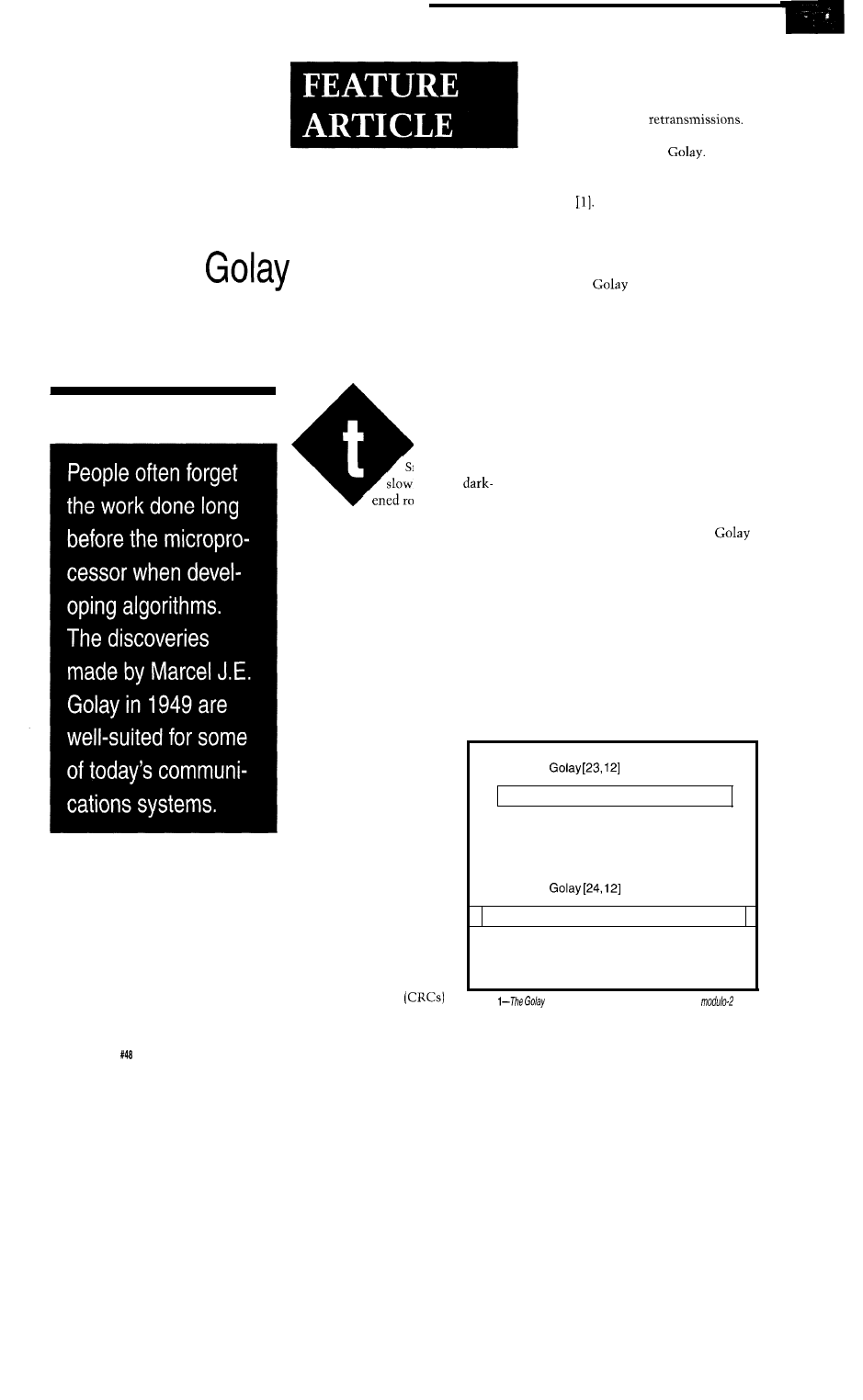
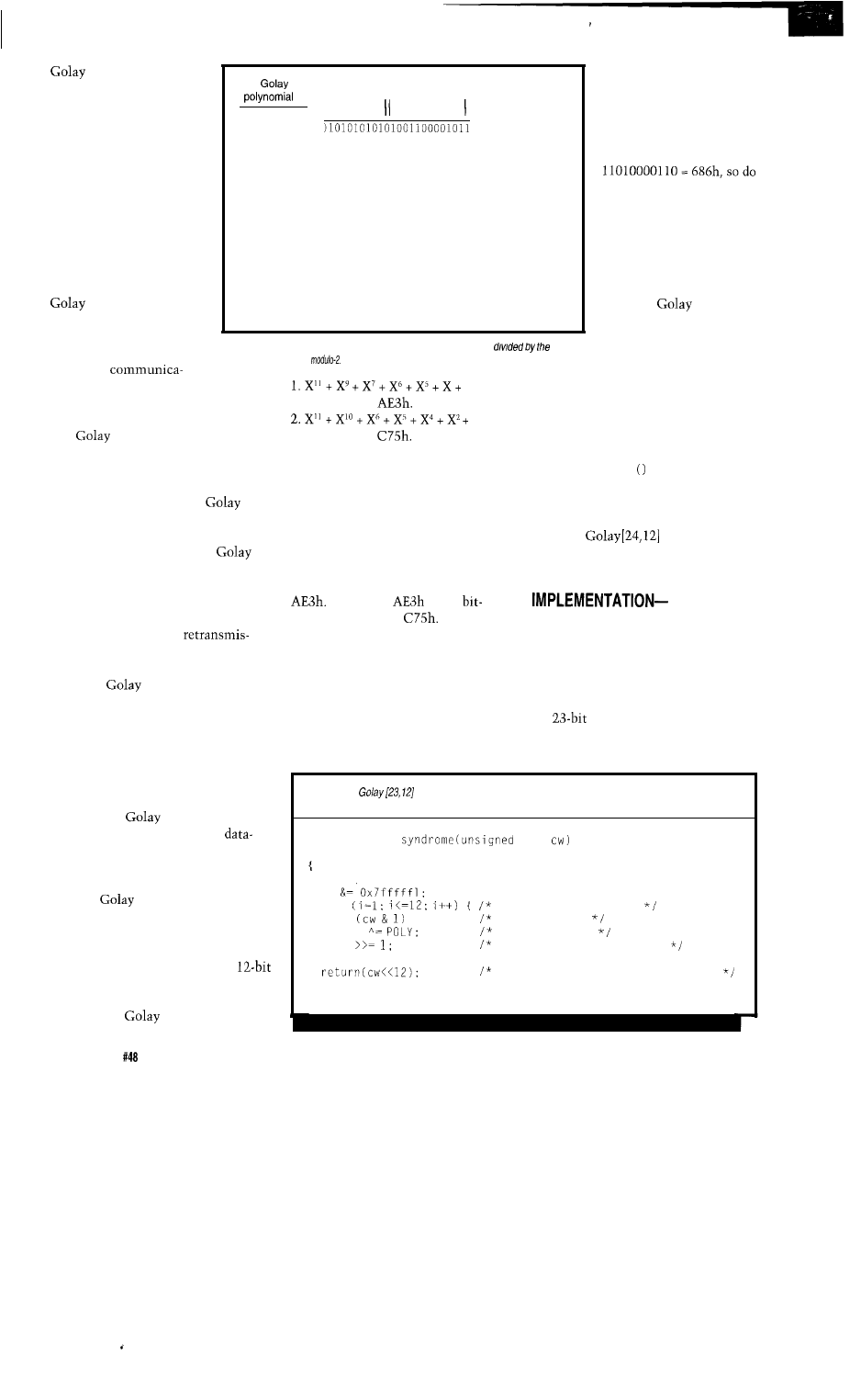
A codeword is formed by taking 12
information bits and appending 11
check bits which are derived from a
modulo-2 division, as with the CRC.
See Figure 1. We will examine the
modulo-2 division process later. The
common notation for this structure is
indicating that the code
has 23 total bits, 12 information bits,
and
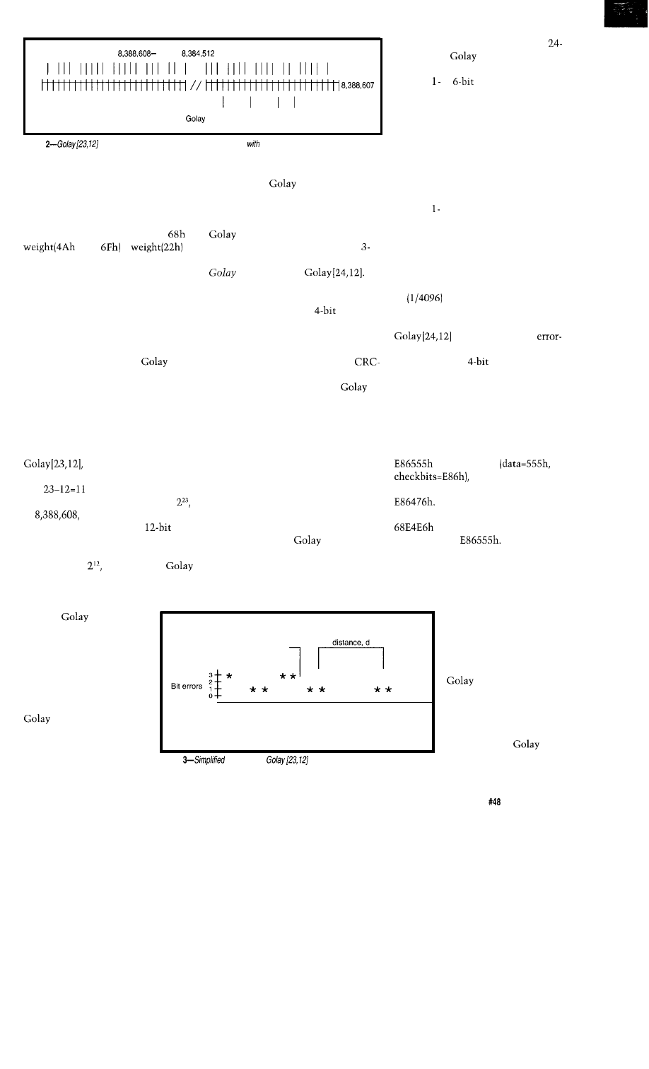
check bits. Since each
codeword is 23 bits long, there are
or
possible binary values.
However, since each of the
information fields has only one
corresponding set of 11 check bits,
there are only
or 4096, valid
codewords. You can think of the
codewords as being distributed along a
number line. See Figure 2.
To augment the power of the
code, an overall parity bit is
usually added, resulting in a clean
byte codeword called the extended
code, noted as
With this parity bit, all odd numbers of
bit errors can be detected in each
codeword, as well as all
errors.
We’ll get to the nuts and bolts of
encoding and decoding codewords
presently.
Before you trash all your old
based designs, be advised that there is
a tradeoff associated with the
code’s error correction ability. If the
code is used merely to detect errors, it
can find a maximum six of them in
any codeword. However, if correction
is performed, only three bits are
correctable. Thus, we trade identifiable
errors for correctability. As the code is
used in an application, situations may
demand changing the correction/
detection methods to suit. Keep this
tradeoff in mind as you examine the
performance of the
code and the
requirements of your application.
The parity bit of the extended
code augments its
corrective properties, allowing all
combinations of
errors to be
detected, but not corrected.
Let’s look at the error-trapping
ability of the code. If error correction is
not attempted, the following are the
Error correction is obviously no
panacea and does carry a penalty. Let
me explain why. When a codeword is
being corrected, the correction algo-
rithm looks for the closest matching
codeword. For example, say codeword
is transmitted
but four bit errors
occur, corrupting the codeword to
When we feed this codeword
into the correction function, it returns
as the closest matching
codeword, not
The receiver
can use the parity bit to detect this
error, but it cannot detect a higher
even number of errors. This illustrates
the fact that every correction algo-
The
codewords
are not really spread evenly
as you count along the
number line, say every few
ticks. Rather, they are
spaced with regard to the
Hamming distance between
them. It turns out that each
codeword has seven
or more bits differing from
every other. Mathemati-
cians say that the code has
a minimum distance, d, of
corrupt
codeword B’
seven bit
characteristic
*
*
*
* * * *
* *
*
*
*
codeword
codeword
codeword
A
B
C
Hamming distance
Figure
illustration of
error correction for three valid
codewords.
seven. They have determined analyti-
cally that the
code can detect
and correct a maximum of (d-1)/2=3
bit errors, in any pattern.
error-detection-only properties per
bit extended
codeword:
100% of to
errors detected, any
pattern
100% of odd bit errors detected, any
pattern
99.988% of other errors detected
Using the error correction facili-
ties of the code, these are the data
reliability rates:
100% of to 3-bit errors corrected,
any pattern
100% of 4-bit errors detected, any
pattern
100% of odd numbers of bit errors
detected, any pattern
0.24% of other errors corrected
rithm has a bit-error-rate
(BER) limit, beyond which
it cannot compensate.
Fortunately, you may
enable the correction
facilities of the given
C routines accord-
ing to your needs.
Figure 3 illustrates
what is happening during
codeword correction. We
see three valid
codewords: A, B, and C.
The X-axis represents
The Computer Applications Journal
Issue
July 1994
25
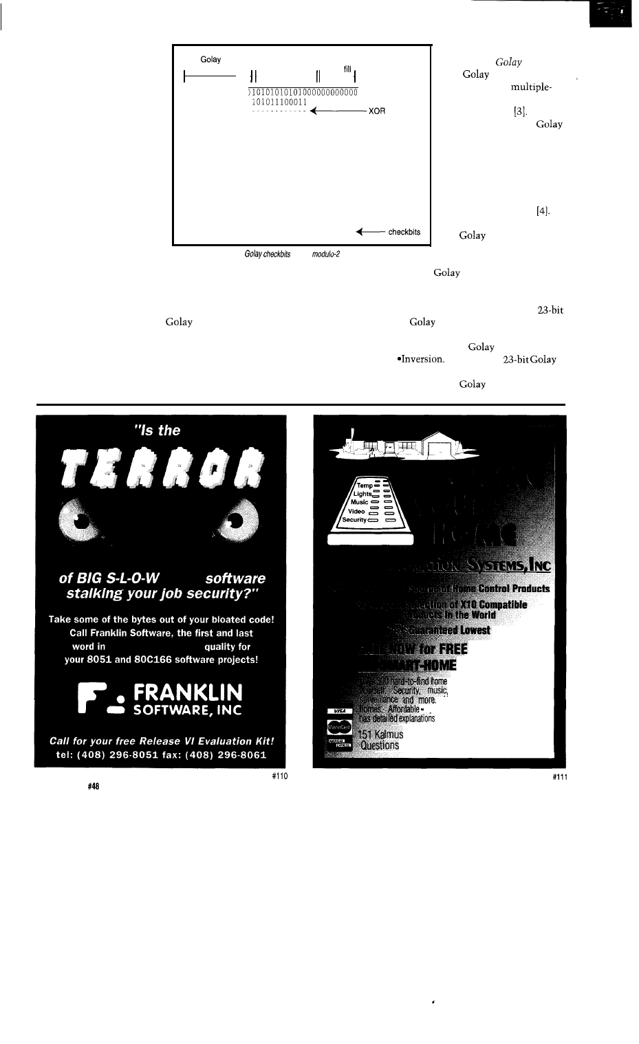
Hamming distance between
these codewords. The Y-axis
represents the number of bit
errors incurred as you move
away from a valid codeword.
Picture the correction
algorithm as taking the
input codeword, say at point
B’, and sliding down the
slope to the nearest correct
codeword. If B’ is a cor-
rupted version of codeword
B, we’re in luck. If B’ is a
very corrupted version of A,
the correction algorithm lies
to us and returns B as the
corrected codeword. You
can see that the minimum
polynomial
info bits zero
101011100011
100100100000
101011100011
111100001100
101011100011
101111011110
101011100011
100111101000
101011100011
01100001011
Figure 4-Calculation of
using
division.
distance,
d,
of the code controls the
amount of corruption that can be
tolerated. This is a simplified explana-
tion, of course. In reality, this diagram
is multidimensional and each
codeword has many error-laden
companions to keep it company in the
abstract boredom of n-space.
Now for some mathematical
curiosities. Among error correction
codes, there is a class known as
perfect
codes.
Briefly, perfect codes are defined
as those where each of the invalid
codewords shown on the number line
in Figure 2, when pumped through the
correction process, will be transformed
into a valid codeword. There are no
orphan uncorrectable information
vectors. Included as perfect codes are
the Hamming codes,
a
one-bit correc-
tion scheme, and the binary
and ternary
codes.
The
codes are the
only nontrivial
error-correcting perfect
codes that exist
The
perfect quality of the
code makes it an object of
beautyintheeyesof
mathematicians, especially
when this property is
expressed in terms of the
optimum packing of spheres
into a region of space
This perfection also makes
the
code useful in the
hands of communications
engineers.
The
codeword has some
very interesting properties:
*Cyclic Invariance. If you take a
codeword and cyclically shift
it by any number of bits, the result
is also a valid
codeword.
If you take a
codeword and invert it, the result is
also a valid
codeword.
Prices
CATALOG
(800-762-7846)
24hrs
control products you can install
video, heating/AC, lighting,
No rewiring. New or existing
systems start at under $20. Catalog
and amazing project ideas.
Dr., Suite M6, Costa Mesa, CA 92626
(714) 708-0610 Fax (714) 708-0614
26
Issue
July 1994
The Computer Applications Journal
Listing
l--The
codeword
encoder
a long integer with fhe format
POLY
or use the other polynomial,
unsigned long
long
int i;
unsigned long c;
cw Oxfffl;
save original codeword
for
examine each data bit
if
test data bit
cw
XOR polynomial
cw
shift intermediate result
assemble codeword
*Minimum Hamming Distance. The
channel. In some cases, the overhead
distance between any two
associated with a resend request is
codewords is always seven
or more bits. The distance between
any two
codewords is
always eight or more bits.
*Error Correction. The correction
algorithm can detect and correct up
to three bit errors per codeword.
much greater than the length of a data
packet. For example, to send a data
packet on a half-duplex or simplex
radio system, the microprocessor must
turn on the transmitter and wait for it
to come up to full power, typically 100
ms. The originating station must incur
the same pretransmit delay when
resending its data. Even if all goes
well, there is 200 ms of wasted time
involved in a resend request. At 1200
bits per second, 200 ms represents 240
WHAT’S THE USE?
The
code is obviously not
able to encode a large amount of data
in one codeword. Twelve bits is the
maximum allowed. So what is its use?
bits of data, a reasonable message
Well, one advantage to error correction
length in some systems. And if the
is the elimination of communications
radio channel is busy with other
retries which can bog down a noisy
traffic, the delays can be longer. The
Listing
parity bit generator checks the overall
parity
of codeword cw.
is even, a is
returned; otherwise, a is returned.
int
long
unsigned char p;
XOR the bytes of the codeword
p = *(unsigned
P
*((unsigned
P
*((unsigned
XOR the halves of the intermediate result
return the parity result
It’s a high integration, 8051
8
ch. 10 bit A/D
2 PWM outputs
registers 16
lines
RS-232 port
Watchdog
W’e’ve
made the
552SBC
by
multi-drop ports
24 more
Real-time Clock
EEPROM
l-ROM
Battery Backup Power Regulation
Power Fail Int.
Expansion Bus
Start
the Development Board all the
peripherals, power supply, manual and a
debug monitor for only $349. Download
your code and debug right on
SBC.
Then use the $149 and up OEM boards
for production. or have us make a custom
board for you. Call now for a brochure!
Use Turbo or MS ‘C’
Intel
Two 1 meg Flash/ ROM sockets
Four battery backed, 1 meg RAM
16 channel, 12 or 16 bit A/D
8 channel, 12 bit D/A
2
serial, 1 parallel
24 bits of opto rack compatible
bits of digital
Real-time clock
Interrupt and DMA controller
8 bit,
expansion ISA bus
Power on the
4 layer board is
provided by a switcher
watchdog and
power
interrupt circuitry.
T h e
IS
a l s o a v a i l a b l e w i t h
Extended Interface
of I/O
a
Field Programmable Gate Array
and a breadboard area. You can now
and
nearly any extra Interface
you need. 188SBC prices start at $299.
Call
right now for a brochure!
$ 1 4 9 8 0 3 2 I C E
Still A
vailable!
8031 SBC as
as $49
S i n c e 1 9 8 3
(619) 566-l 892
70662.1241
The Computer Applications Journal
Issue
July 1994
27
code can reduce the
number of retransmission
events by allowing the
receiving end to correct
some errors in the re-
ceived data, decreasing the
probability that the
channel will get over-
loaded.
In other situations,
there may be no resend
request possible (e.g., with
a one-way infrared or
ultrasonic data link). The
code allows such
systems to increase the
probability of one-way,
error-free reception.
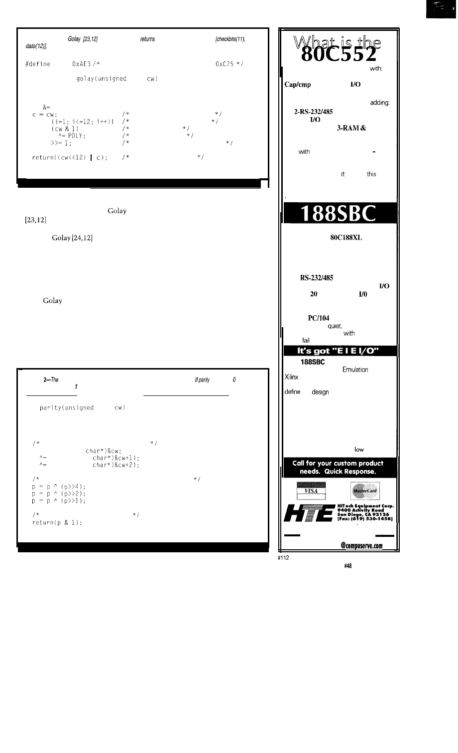
Some
, ,
checkbits
101011100011
101011100011
100100101100
101011100011
111100111100
101011100011
101110111111
101011100011
101011100011
101011100011
00000000000 f---syndrome=
0
Figure
5-The syndrome is the remainder left after the codeword is
generating polynomial,
If
the
Golaycodewordis valid, the syndrome is zero
(least-significant bit first)
and perform the division
in Figure 4.
We only care about
the bit-reversed remainder
from the division,
not even write down the
quotient. Putting the
codeword together for
transmission, we get
686555h. A parity bit
could be added to the
codeword to make an
extended
code. Of
course, you can mish-
mash the bits around in
any order for transmission,
tions channels are more prone than
others to burst errors, where many
consecutive data bits are corrupted.
The
code alone is not able to
correct bursts of errors over three bits
long in a single codeword. However,
when augmented with a technique
called bit interleaving, the
code’s small, modular format allows
the correction of large burst errors, as
we will see. The unmodified
code really shines in applications
prone to random bit errors though, and
it tolerates a disgusting (3 bit errors)/
(24 bits per codeword) = 12.5% bit
error rate without data
sions.
1,
coefficients
just as long as they are
reassembled correctly before doing the
decoding.
Of course, a disadvantage of the
extended
code is that you must
transmit as many check bits as data
bits. Maybe you are asking, why not
just send the data twice, without
check bits? The answer is that no error
correction is possible in such a system.
How would you know which of two
different messages, if not both, were
corrupt? The
code allows error
correction in exchange for the
doubling price.
IMPLEMENTATION-ENCODING
The
code is encoded just
like the CRC, using modulo-2 divi-
sion. However, there are only 12
information bits per codeword, so you
must break your data down into
chunks and encode each as one
codeword. The characteristic polyno-
mials for the
code are:
1,
coefficients
Yes, there are two. You only need
to use one of them because they both
have the same properties as mentioned
above, though they generate differing
checkbits. Pull out your favorite
buffalo nickel and choose a polyno-
mial! We will use the coefficients of
the X terms of the first polynomial,
(Note that
is the
reversed version of
There is a
greater power at work here.)
The encoding algorithm is shown
in Listing 1. Long integers are used to
conveniently store one codeword. The
routine pa r i ty
adds the parity bit
to complete the extended codeword. It
is shown in Listing 2. You can see
reference 3 for matrix methods which
encode a
codeword
directly without an explicit parity
routine.
DETECTING ERRORS
An example worked out by hand
illustrates the modulo-2 division
process. Remember that in modulo-2
division, we XOR instead of subtract.
The data we wish to encode is 555h.
To generate the 11 check bits, append
11 zeros onto the bit-reversed data
Detection of errors in a codeword
is easy. First, we use the overall parity
bit to check for odd numbers of errors,
possibly failing the codeword on that
basis. If parity is correct, we compute
the
syndrome of the codeword
and check for zero. The syndrome is
the remainder left after the codeword
Listing 3-A
codeword syndrome generator. A table of infermediate results could also be
used to speed the process.
unsigned long
long
int i:
cw
for
if
cw
cw
examine each data bit
test data bit
XOR polynomial
shift intermediate result
value pairs with upper bits of cw
28
Issue
July 1994
The Computer Applications Journal
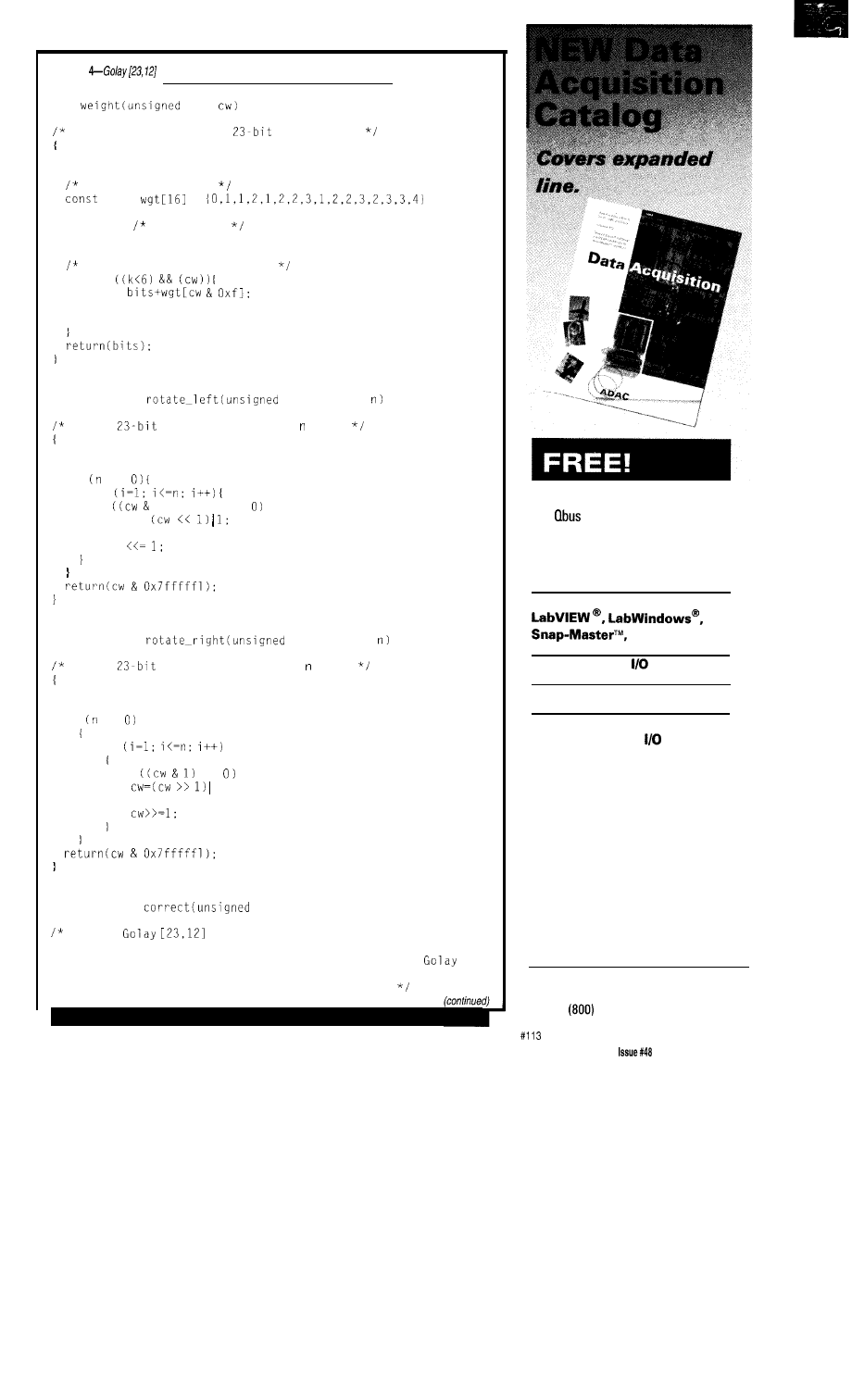
Listing
codeword correction routines.
int
long
Calculate the weight of
codeword cw.
int bits,k;
nibble weight table
char
=
bits = 0; bit counter
k = 0:
do all bits, six nibbles max
while
bits =
cw >>= 4;
k++;
unsigned long
long cw, int
Rotate
codeword cw left by bits.
int i;
if !=
for
if
0x4000001) !=
cw =
else
cw
unsigned long
long cw, int
Rotate
codeword cw right by bits.
int i;
if !=
for
if
!=
0x4000001;
else
unsigned long
long cw, int *errs)
Correct
codeword cw, returning the corrected
codeword. This function will produce the corrected codeword for
three or fewer errors. It will produce some other valid
codeword for four or more errors, possibly not the intended one.
*errs is set to the number of bit errors corrected.
1994 120 page catalog for PC, VME,
and
data acquisition. Plus infor-
mative application notes regarding
anti-alias filtering, signal condition-
ing, and more.
NEW Software:
and more
NEW Low Cost
Boards
NEW Industrial PCs
NEW Isolated Analog and
Digital Industrial
New from the inventors of
plug-in data acquisition.
Call, fax, or mail for your
free copy today.
ADAC
American Data Acquisition Corporation
70 Tower Office Park, Woburn, MA 01801
Phone:
648-6589 Fax: (617) 938-6553
The Computer Applications Journal
July
1994
29
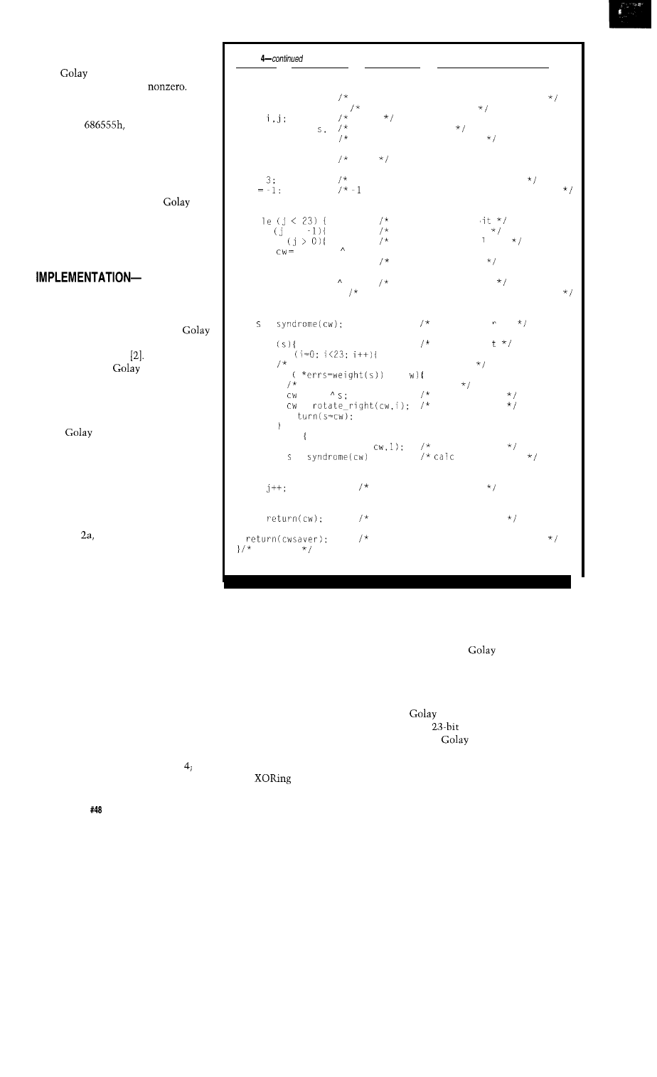
is divided by the generating polyno-
mial, modulo-2. If the codeword is a
valid
codeword, the syndrome is
zero, otherwise it will be
Figure 5 shows a sample calculation
using the previously constructed
codeword,
bit reversed for
the division process.
The routine in Listing 3 does the
same sort of calculation. You could
use a table of intermediate results to
speed the process. These routines are
all you need to implement a
error detection scheme. As above, you
can detect up to six bit errors per
codeword and, with the parity bit, all
odd numbers of errors.
CORRECTING ERRORS
Cue the smoke and mirrors; error
correction is not so trivial. It relies on
the cyclic invariant properties of
codewords in a scheme called system-
atic search decoding
There are
other methods of
error correc-
tion listed in the references, though I
have found this one easy to implement
in software. This is a “nearest neigh-
bor decoder,” because it determines
which
codeword is closest in
terms of Hamming distance.
Here is a sketch of the systematic
search algorithm.
1. Compute the syndrome of the
codeword. If zero, no errors exist so go
to step 5. If a trial bit has been toggled,
go to step
else go to 2.
2. If the syndrome has a weight of
three or less, the syndrome matches
the error pattern bit-for-bit and can be
used to XOR the errors out of the
codeword; if so, remove the errors and
go to step 5, otherwise proceed to step
3.
2a. If the syndrome has a weight of
one or two, the syndrome matches the
error pattern bit-for-bit and can be
used to XOR the errors out of the
codeword; if so, remove the errors and
go to step 5, else proceed.
3. Toggle a trial bit in the
codeword in an effort to eliminate one
bit error. Restore any previously
toggled trial bit. If all 23 bits have been
toggled and tried once, go to step
else go to step 2a.
Listing
unsigned char w;
current syndrome limit weight, 2 or 3
unsigned long mask: mask for bit flipping
int
index
unsigned long
calculated syndrome
cwsaver:
saves initial value of cw
cwsaver = cw;
save
*errs = 0;
w =
j
initial
= no
mask = 1:
wh
f !=
if
cwsaver mask:
mask += mask:
cw = cwsaver mask;
w = 2;
lower
=
if
for
syndrome weight threshold
trial bit flipping on first pass
flip each trial b
toggle a trial bi t
restore last tria
point to next bit
bit
flip next trial b it
the threshold whi le
look for er
errors exis
if
re
else
<=
syndrome matches error pattern
= cw
remove errors
=
unrotate data
cw = rotate-left
=
bit diddling
check syndrome of each cyclic shift
ors
toggle next trial bit
else
next pattern
new syndrome
return corrected codeword
return original if no corrections
correct
4. Rotate the codeword cyclically
left by one bit. Go to step
1.
5. Rotate the codeword right to its
original position, if needed.
The idea is to fiddle with the
codeword until the syndrome has a
weight of three or less, in which case
we can XOR the syndrome with the
codeword to negate the errors. How-
ever, if a trial bit has been toggled, we
might have introduced an error
(making a total of four), so the thresh-
old for
the errors away in step
2a must be reduced by one for safety,
to two or less.
We are relying on the perfect
nature of the
code for a termi-
nating condition of the search algo-
rithm. Normally, we would test in
step 4 to see if all 23 codeword shifts
had already been tried, but since the
code is perfect, we know that
each
value maps to exactly one
correct
codeword and the
algorithm will terminate. However,
since programmers are not perfect, I
test to guard against infinite loops.
30
Issue
July 1994
The Computer Applications Journal
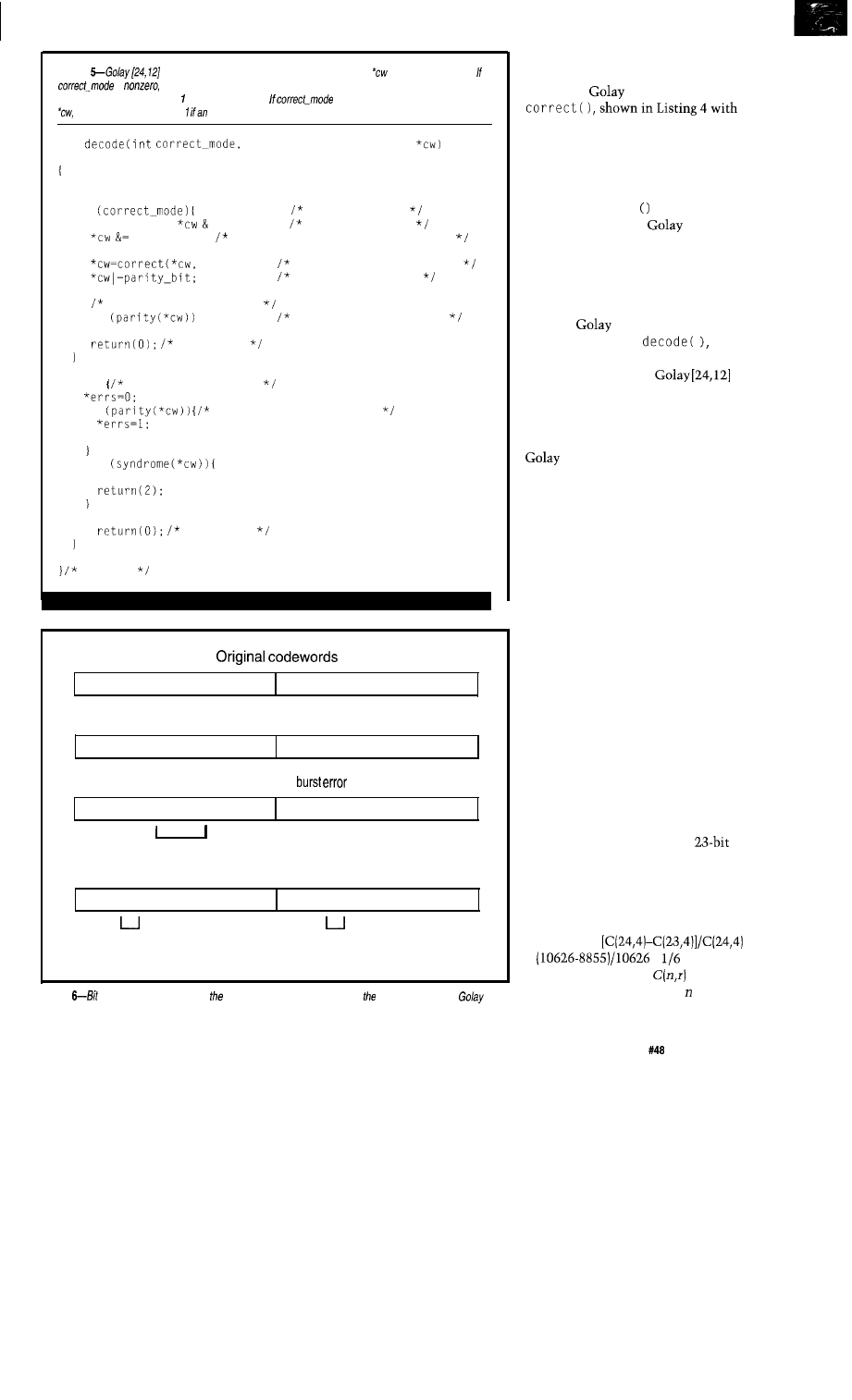
Listing
codeword decoder. This function decodes codeword
in one of two modes.
is
error correction is attempted, with *errs set to the number of bits corrected, and
returning 0 if no errors exist or if parity errors exist.
is zero, error detection is performed on
returning 0 if no errors exist,
overall parity error exists, and 2 if a codeword error exists.
int
int *errs, unsigned long
unsigned long parity-bit;
if
correct errors
parity-bit =
0x8000001; save parity bit
-0x8000001; remove parity bit for correction
errs);
correct up to three bits
restore parity bit
check for 4 bit errors
if
odd parity is an error
return(l);
no errors
else
detect errors only
if
odd parity is an error
return(l);
if
*errs=l;
else
no errors
decode
111111111111111111111111 000000000000000000000000
Interleaved codewords
101010101010101010101010 010101010101010101010101
After six bit
101010101001010110101010 010101010101010101010101
6 bit-errors
After de-interleave
111110001111111111111111 000001110000000000000000
three bit-errors
three bit-errors
(correctable)
(correctable)
Figure
interleaving can be used in presence of burst errors to extend effectiveness of the
method.
The rotations and trial-bit book-
keeping make for a nontrivial-looking
routine for
error correction,
its support routines. These routines
are written for simplicity. You can
tighten them up for optimum perfor-
mance on your favorite scream
machine.
The
c o
r r e c t.
function returns
the nearest matching
codeword.
Note that this may not be the code-
word you expect if there are more than
three bit errors because the received,
corrupted codeword may be closer, in
terms of Hamming distance, to a
different
codeword.
Listing 5 shows
a
function that handles either detecting
or correcting errors in
codewords, returning the corrected
codeword and error detection status
upon exit.
The parity bit in the extended
code is used as a final check on
the integrity of the corrected code-
word. If the received codeword has the
right parity, the codeword is accepted,
otherwise it is rejected. The overall
parity bit is used to trap the occur-
rence of odd numbers of errors and
four-bit-error-laden codewords. That
the overall parity bit traps four-bit
errors is explained by the fact that the
correction algorithm introduces three
additional bit changes to get to the
nearest codeword, which is seven bits
distant from the original, noncorrupt
codeword. So, the four-bit errors, plus
three additional changed bits, make
seven bit changes total.
Note that toggling any bit(s) in a
codeword an odd number of times will
change the codeword’s parity, allowing
the overall parity check to trap four-bit
errors, but only after correction has
been attempted. If one of the four
errors is in the parity bit, the
codeword will be corrected properly,
but must be trashed because the total
parity is wrong and the receiver will
not know exactly which bits were
corrupted. For the interested few, this
will occur in
=
=
of cases of
four-bit errors, where
is the
number of combinations of things
taken
r
at a time.
The Computer Applications Journal
Issue
July 1994
3 1
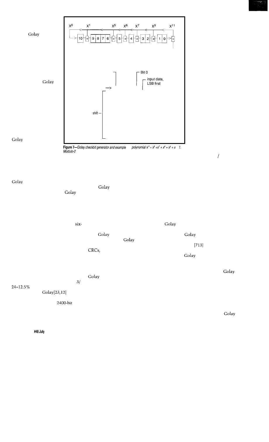
BACK TO THE
REALITY
In practice, I have
used the
code on
radio channels and
telephone lines and have
found it to be robust.
Practically, one cannot
rely on the error correc-
tion facilities alone if
there is a two-way
communication link.
Rather, I use the
code to reduce the
incidence of message
resends. Messages are
always checked for
framing errors and other
problems which are
specific to the informa-
tion transmitted and the
message context.
A frailty of the
code is its inabil-
ity to detect large bursts
of bit errors. However, a
technique called bit
Input
(LSB first)
Shift register
Bit10
Shift register
initialregistervalue
00000000000
1
11000111010
1
2
01100011101
0
3
00110001110
1
4
00011000111
0
5
00001100011
1
value after
6
11000001011
0
7
01100000101
1
8
11110111000
0
9
10111100110
1
10
01011110011
0
11
00101111001
1
12
11010000110
0
for
+
division example is shown in figure 5.
interleaving can remedy the situation.
Assume we have a block of 48 bits to
transmit-two codewords. An error of
four consecutive bits will corrupt a
data packet and elicit a retrans-
mission. However, if we transmit the
48 bits not in two sequential
codewords, but in a scrambled order,
burst errors will be distributed over
both codewords when the bits are
unscrambled. See Figure 6.
The two resulting codewords in
Figure 6 are correctable, whereas a
bit burst error in the original data
would not have been. In general, the
more data you interleave, the longer
the burst of errors the message can
withstand. The correctable burst size,
in bits, is three times the number of
codewords interleaved. The penalty is
the reception delay incurred between
the first and last bit of any one
codeword. Using this method, it is
theoretically possible to extend the
burst error correction
capability of the
code to
arbitrarily long blocks of data. Imagine
sending a 100-codeword,
message and correcting a burst error of
300 consecutive bits! Unfortunately,
interleaving data in this fashion is
not fun or memory efficient, but that’s
life.
You may have noticed that the
codewords used in the above examples
are OOOOOOh and FFFFFFh. These are
valid
codewords. This alerts us
to a possible communications failure
mode: the stuck bit. If the hardware
were to fail in midmessage, it could
emit a default 1 or 0, depending on its
configuration and the data format.
This could be disastrous if undetected
because the dead circuit would be
interpreted as sending consecutive,
valid
codewords. But happily,
we can modify the
checkbits
slightly, as is often done when using
by inverting one or more of
them before transmission, and
reinverting the same bits before
decoding at the receiver. This way,
OOOOOOh and FFFFFFh are not valid
codewords, and the chances of a
stuck data line mimicking good data
are greatly reduced. In fact, it is always
good practice to structure your
communications protocol so that a
continuous 0 or
1
block of data cannot
be misconstrued as valid information.
By the way, do not ignore the
information that spins off of the
correction process: The
number of errors
corrected in each
codeword. This is
valuable information
about the BER on the
communications
channel, useful for
judging its quality. Say
you have a data system
running over the
telephone network in a
remote area and these
lines are not the best
quality, degrading some
with the weather. This is
not a contrived example.
Some Mom and Pop
telcos run with twine
and tin cans. It would be
nice to optimize the data
rate based on the current
condition of the lines.
Counting corrected bit
errors is one way to do
this. As the error rate
(corrected bits total
bits) passes a critical value, the data
rate can be cut, with the cooperation
of transmitter and receiver, of course.
When the sun comes out, the data rate
can be increased as the BER goes down
to acceptable levels. (Note that this
technique has a BER measurement
ceiling of 12.5% because every corrupt
codeword will have at most three
correctable errors.)
I am sure some readers are
hardware types, wondering if the
code can be easily implemented
in hardware. One manufacturer I know
of makes a
encoder/decoder in
IC form: Space Research Technology
(Houston, Tex.,
782-2244). This
device is amenable to serial data
streams of
encoded data. They
also publish some application notes
mathematically detailing the advan-
tages of bit interleaving and the
code in general.
The references for this article
describe various circuits suitable to
the task of decoding-I mean suitable
as a function of your personal Boolean
logic overload level. The circuits are
not trivial by any means, though the
relatively small number of 4096
codewords suggests that ROM-based
32
Issue
1994
The Computer Applications Journal
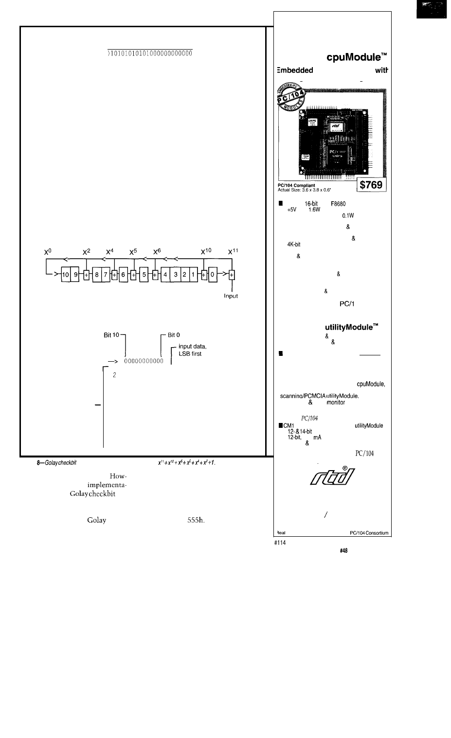
Hand verification of shift register calculation
1 1 0 0 0 1 1 1 0 1 0 1
110001110101
110110111110
110001110101
111001011000
110001110101
100010110100
110001110101
100110000010
110001110101
101111101110
110001110101
111100110110
110001110101
110100001100
110001110101
00101111001
(LSB first)
Shift register
Shift register
initial register value
1 1 0 1 0 1 1 1 0 0 0 1 1
value
after shift
11111001001
0
3
01111100100
1
4
00111110010
0
5
10110001000
1
6
01011000100
0
7
10000010011
1
8
11101111000
0
9
11011001101
1
10
11000010111
0
11
01100001011
1
- 1 2
10011110100
0
Figure
generator and example for polynomial
decoders may be economical.
each. The final register value in Figure
ever, the shift register
7 is 11010000110, which we reverse
tions of the two
and compare with the result of Figure
generators are simple, and are shown
4, finding agreement. This circuit is
in Figures 7 and 8. As before, either
equivalent to that calculation with
circuit produces valid
checkbits.
input data of
The final register
Also shown is a sample calculation for
value of Figure 8 is 10011110100,
Replace Four
Conventional PC/l 04
Modules with
One
CMF8680
PC/XT Controller
Intelligent Power Management
n PC/XT compatibility with 286 emulation
14 MHz,
C&T
CPU
n
only;
at 14.3 MHz, 1 W at 7.2 MHz
n Intelligent sleep modes,
in Suspend
n ROM-DOS and RTD enhanced BIOS
n Compatible with MS-DOS real-time
operating systems
n 1 M bootable solid state disk free software
n
configuration EEPROM (2K for user)
n 2M on-board DRAM
n IDE floppy interfaces
n CGA CRT/LCD controller
n Two RS-232 ports, one RS-485 port
n Parallel, XT keyboard speaker ports
n Optional X-Y keypad scanning/PCMCIA
interface
n Watchdog timer real-time clock
Expand This Or
Any
04 System
with the
CM1 06 Super VGA
Controller
n Mono/color STN TFT flat panel support
n Simultaneous CRT LCD operation
n Resolution to 1024 x 768 pixels
Displays up to 256 colors
( $ 3 9 5 1
Speed Product Development with the
SK-CM1 06-X Starter Kit
Your kit includes the CMF8680
CM106 SVGA controller, CM102 keypad
CMF8680
cable-kit VGA
cable for just
$1295.
Additional
compliant modules from RTD:
04 1.8” hard drive carrier
n
analog I/O modules
n
4-20
analog output modules
n opto-22 digital I/O modules
For
more information on our
and
ISA bus products, call today.
Real Time Devices USA
200 Innovation Blvd.
l
P.O. Box 906
State College,
PA
16804
USA
(814) 234-8087 Fax: (814) 234-5218
RTD Europa
l
RTD Scandinavia
Time Devices is a founder of the
The Computer Applications Journal
Issue
July 1994
33
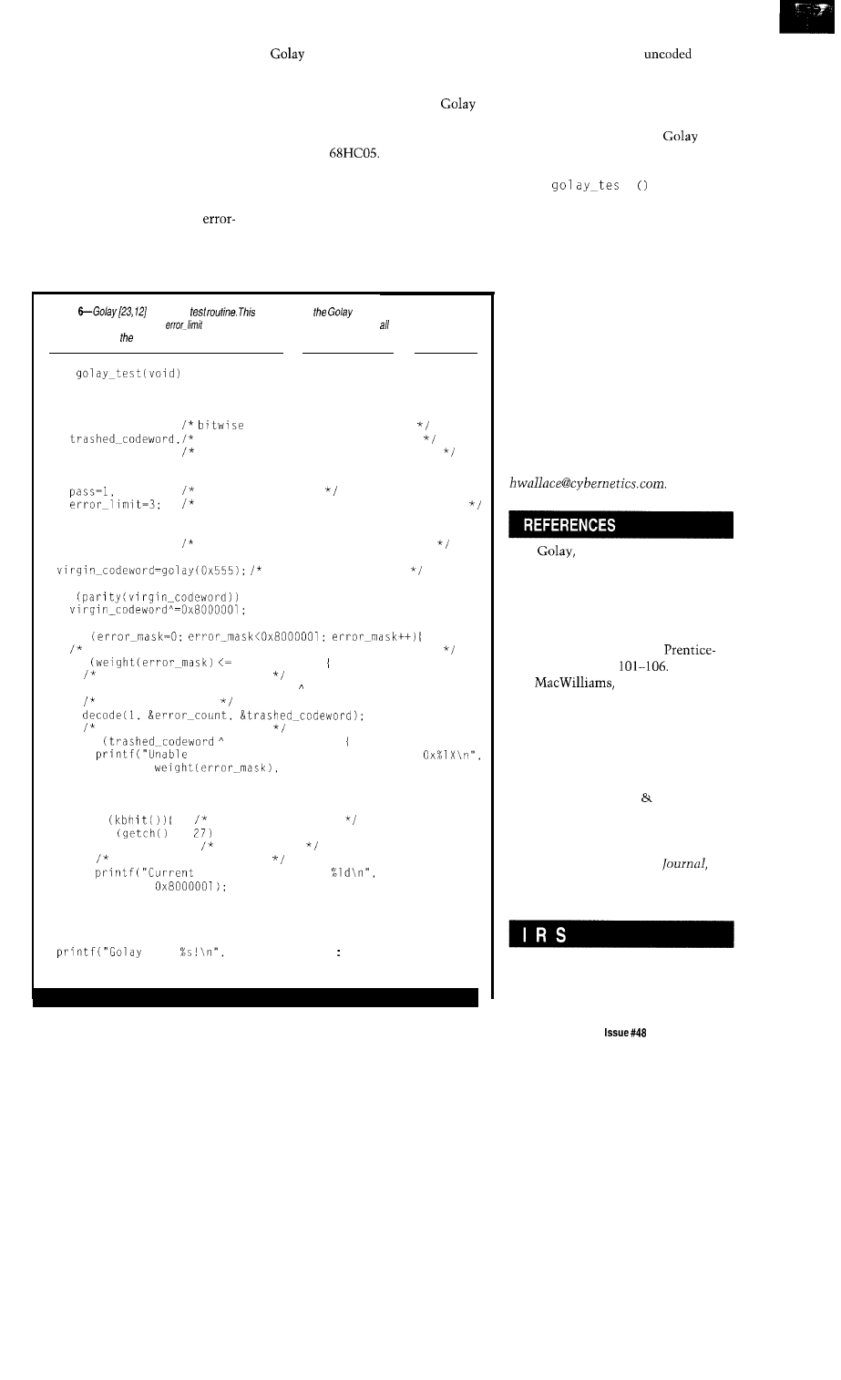
which agrees with the accompanying
modulo-2 division remainder, when
reversed. Also notice that, like the two
polynomials, the shift register circuits
are mirror images of each other,
suggesting that some more gating
could make one bidirectional shift
register encode either polynomial.
CONCLUSION
Of course, there are other
correcting codes, but it is generally
agreed in the literature that they are
more difficult to correct than the
code, though the Hamming
codes are easier. In general, the more
capable the code, the more processor
power it takes to decode. The
code could be used in even the small-
est microcontrollers, such as the PIC
series and
As a parting imperative, do your
homework before choosing this or any
other error detection/correction code.
There are some important ideas that I
did not discuss here, such as coding
gain. This is an expression of the
improvement in performance of the
Listing
codeword
function tests
routines for detection and
correction of various patterns of
bit errors. The error-mask cycles over possible values, and
error-limit selects maximum number of induced errors.
void
unsigned long
error-mask,
mask for inducing errors
the codeword for trial correction
virgin-codeword; the original codeword without errors
unsigned char
assume test passes
select number of induced bit errors here
int
error-count;
receives number of errors corrected
make a test codeword
if
for
filter the mask for the selected number of bit errors
if
error-limit)
you can make this faster!
trashed_codeword=virgin_codeword error-mask;
induce bit errors
try to correct bit errors
if
virgin-codeword)
to correct %d error mask induced =
error-mask);
pass = 0;
if
look for user input
if
==
return;
escape exits
other key prints status
test count = %ld of
error-mask,
test
pass ? "PASSED" "FAILED");
coded channel over the
channel. Each code has a different
coding gain for various channel noise
conditions. You can also examine the
references for matrix methods of
encoding and decoding the
and
other codes.
Finally, let me recommend the
routine
t
in Listing 6. It
does tests to verify the operation of
your encoding and decoding routines
by letting you induce a selectable
number of errors in a test codeword on
which correction is attempted. Always
test your versions of these routines
thoroughly before deploying; it is easy
to slip up on a loop index and get a
data-dependent error detector or
corrector, which is certain to ruin a
couple of nights’ sleep.
q
Hank Wallace is the owner of Atlantic
Quality Design Inc., an embedded
systems hardware and software design
firm located in Rural Hall, N.C. He
may be reached at (910) 377-2843 or
1.
Marcel J.E., “Notes on
Digital Coding,” Proceedings of
the IRE, Vol. 37, June 1949, pp.
657.
2. Lin, Shu, An Introduction to
Error Correcting Codes.
Englewood Cliffs, N.J.,
Hall, 1970, pp.
3.
Sloane, The
Theory of Error Correcting
Codes. Amsterdam, North
Holland Publishing Co., 1977,
pp. 64-65, 482, 634-635.
4. Pless, Vera, Introduction to the
Theory of Error Correcting
Codes. John Wiley Sons, 1982,
pp. 1-13.
5. Shannon, C.E., “A Mathemati-
cal Theory of Communication,”
Bell System Technical
Vol. 27, July 1948, pp. 379-423;
October 1948, pp. 623-656.
404
Very Useful
405 Moderately Useful
406 Not Useful
The Computer Applications Journal
July 1994
3 5

The Great
Encryption
Debate
John
deciphering messages
and information. The word conjures up
images of espionage, spies, hostile
government action, and top secret
information. We don’t usually associ-
ate this word with privacy-your pri-
vacy-but it is this facet of cryptology
that is being argued today in our courts
and among government agencies.
ENCRYPTED PRIVACY?
The arena where electronic bits of
information are transmitted through
data conduits is loosely termed
“cyberspace.” Currently, in cyberspace
there’s no guarantee of privacy.
Transmitted messages may be inter-
cepted and read indiscriminately. This
possible invasion of privacy is not just
limited to
on your local BBS or
on Internet. Our national telephone
network, which handles voice and fax
as well as computer telecommunica-
tion, is vulnerable. Additional data
conduits like cable television systems
and satellite feeds are becoming more
commonplace all across the country.
These newer networks are vulnerable
to interception as well.
To better grasp the threat, imagine
a company that routinely transmits
bids or promotional information to
field agents through one of these
networks. The company can be put at
a severe disadvantage if a competitor
gains access to this information.
The dark side of our information
age is that technically skilled
sometimes romantically referred to as
phreakers and crackers-can create
havoc in your life. For a while, crack-
ers were making national news by
breaking into secured government
databases.
Intercepting various unprotected
data communications makes most
people easy targets for others to gain
access to confidential material.
Anyone who has been electronically
mugged has very little sympathy for
these criminals. By stealing credit card
numbers, they are capable of making
purchases, charging telephone calls to
your phone number, reading your
and listening to cellular phone
conversations.
The problem is growing. Our
national data network increases in size
and complexity daily. It is changing
and defining the methods by which
people communicate, information is
transferred, and business is conducted.
It is therefore becoming increasingly
important to secure the privacy of the
networks and reduce their vulnerabil-
ity to interception.
Business has been less than
responsive to this threat. For instance,
credit card companies justify their
exorbitant
interest rates because
they are needed to compensate for the
tremendous amount of credit card
(read “electronic”) fraud and thievery.
These companies should be doing
much more to prevent electronic fraud
instead of just passing the cost on to
honest consumers in the way of high
interest rates.
Rep. Edward J.
(D-Mass),
the chairman of the House Telecom-
munication and Finance Subcommit-
tee, had this to say about privacy:
“Whether it’s a cellular phone conver-
sation, computer data, a fax transmis-
sion, a satellite feed, cable program-
ming, or other electronic services,
encryption is the key to protecting
privacy and security.” He stated
further that “developing a national
policy for encryption and its uses is
therefore a process of fundamental
importance for the future of our
national networks and our competitive
position internationally.”
ENTER THE CYPHERPUNKS
That’s
not
Let’s not
confuse these similar sounding
monikers. The cypherpunks want to
36
Issue July 1994
The Computer Applications Journal
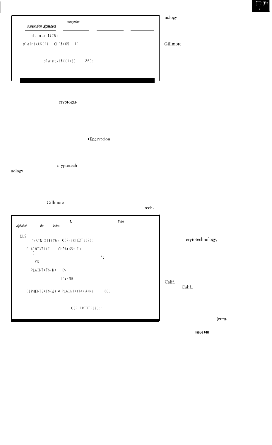
Listing l-One
of the simplest forms of
is substitution. This piece of code prints out the 26
possible
10 DIM
20 FOR i = 0 TO 25
30
=
40 NEXT i
50 FOR j = 0 TO 25
60
FOR i = 0 TO 25
70
MOD
80
NEXT i
90
99 NEXT j
see widespread public use of crypto-
*Government investment leads to
technology. They see the individual’s
government control.
privacy protected through
*Government control is detrimental to
phy. However, they face powerful
governmental and political obstacles.
The end of the cold war hasn’t
eliminated the need for cryptography
and secret codes used by our govern-
ment. But it should have alleviated
some of the regulations concerning
private use of cryptotechnology. The
government still classifies crypto-
technology with hard military weap-
ons such as tanks. The U.S. govern-
ment agency in charge of
is the National Security
Agency (NSA). The cypherpunks see
the NSA as trying to keep its mo-
nopoly on cryptotechnology intact.
One of the most outspoken and
visible members of the cypherpunks is
John Gillmore. Mr.
has this
to say on the subject:
the development of the media.
*Government seized the control of
radio and television in their
infancy. Since then the media has
never had full first amendment
rights or protection.
technology is the key for
people and companies to maintain
their privacy over the networks.
The government should cease its
involvement.
John has fought legal battles with
the NSA on a few fronts. So far he has
been victorious.
BATTLE LINES
The lines are drawn. On one side
you have the cypherpunks who feel
that good public cryptographic
Listing
2-Going one step beyond Listing fhis code first asks for a key letter,
generates a cipher
initiated by key
5
1 0
15
20
25
30
35
40
45
50
55
60
65
70
75
80
85
90
95
DIM
FOR I = 0 TO 25
=
NEXT
PRINT "Enter capital letter to code:
INPUT
FOR N = 0 TO 25
IF
= THEN 60: REM code
NEXT N
CLS: PRINT “Error
REM code:
FOR J = 0 TO 25
MOD
NEXT J
PRINT: PRINT: PRINT "This is the cipher alphabet:"
FOR I = 0 TO 25: PRINT
NEXT
END
safeguards our privacy. The
NSA feels this is compromising our
national security.
The government has threatened
private cryptographers with jail. John
was threatened by the NSA
stating that he was on the verge of
violating the Espionage Act. A convic-
tion would have sent him to jail for 10
years.
How can the government threaten
private citizens? Easily: as stated
previously, the government classifies
cryptographic tools with military
tanks and bomber planes.
THE WASHINGTON CONNECTION
The Administration wants
America to encrypt its information to
protect it from unauthorized access.
The encryption scheme, contained in
the government-sponsored Clipper
chip, includes voice as well as data
information sent over communication
lines. A major catch in this plan is that
only the government-approved
encryption is allowed in any device
used by the government or in govern-
ment projects. Other encryption
methods continue to be legal for
domestic use, but only in
nongovernment applications.
The second catch is the potential
for a trap door in the encryption chip’s
program that would allow law enforce-
ment agencies to decipher any en-
crypted data. Therefore, this method of
encryption doesn’t alleviate concerns
that the government could abuse its
ability to tap into the privacy of the
citizenship.
Of course, organized crime would
use its own
anyway.
So a trap door would only be effective
for spying on small incidental crooks
and private citizens.
The encryption algorithm touted
by the Administration is contained in
an integrated circuit. This chip,
designed by Mykotronx in Torrance,
and manufactured by VLSI in
San Jose,
is nicknamed “Clip-
per.” It is a 12-Mbps encryption
coprocessor. The OEM cost of the chip
is $26 when purchased in large
quantities, which trickles down to
an increase of $100 in the street price
of any electronic equipment
The Computer Applications Journal
July1994
37
puter, phone, fax] that contains the
chip.
SOFTWARE VS. HARDWARE
There are less expensive encryp-
tion chips on the market than the
Clipper. Usually anyone interested in
encryption takes a software approach.
It may be a little slower than hard-
ware, but the recurring cost is much
less. Speed only becomes a critical
consideration when it’s necessary to
secure fast communication such as
video or voice communication.
RECENT EVENTS
On February 4, 1994, the U.S.
Government officially endorsed the
Clipper chip and directed the Com-
merce Department’s National Institute
of Standards and Technology (NIST)
and the Treasury Department to hold
in escrow the keys used to unlock the
Clipper codes. It also establishes new
procedures for exporting products
using Clipper to most countries.
The government has formed an
interagency group whose job it is to
develop encryption technologies that
could serve as alternatives to Clipper.
The Clipper endorsement contains
three flaws according to a policy paper
released in January 1994 by the
Institute of Electrical and Electronic
Engineers: a classified algorithm, the
key-escrow system, and an encryption
standard developed for public use
without public scrutiny.
The Clipper chip has developed
many industrial and congressional
opponents. So far, Novell, AT&T,
Citicorp, Computer Associates,
Hughes Aircraft, Motorola, and other
major corporations openly oppose the
Clipper encryption standard. The
failure of recent administrations lies in
the fact that they did not seek greater
industry participation before proposing
the Clipper chip. Further, they ignored
protests from industry and Congress.
THE BIG BROTHER ISSUE
The Clipper chip can provide
government agencies with unprec-
edented wire tapping ability.
Ideally, the Clipper chip encrypts
(scrambles) communication to every-
one except the intended recipient. The
Listing
a bit more
the program
in Listing this program
includes lower case and will encrypt a
single line of
5
10
15
20
25
30
35
40
45
50
60
65
70
75
80
85
90
95
=
+
=
NEXT I
PRINT "Enter letter key code:":
INPUT
FOR N = 0 TO 25
IF
= THEN 65: REM code
IF
= THEN 65: REM code
CLS: PRINT "Error 1": END
REM code:
FOR J = 0 TO 25
=
MOD
=
MOD
NEXT J
PRINT: PRINT: PRINT "This is the cipher alphabet:"
DIM
FOR I = 0 TO 25
FOR I = 0 TO 25: PRINT
NEXT
10 FOR I = 0 TO 25: PRINT
NEXT
15 PRINT: PRINT "Enter a one-line message to encode
20 INPUT
25 MLEN =
30 FOR I = J TO MLEN
35
FOR J = 0 TO 25
40
IF
=
THEN GOT0 155
45
IF
=
THEN GOT0 165
50
NEXT J
155
160
GOT0
165
170 NEXT I
175 PRINT:
180 PRINT
185 END
=
170
=
PRINT "The enciphered message is:": PRINT
key code to unscramble communica-
tion is held by two separate govern-
ment agencies. The government has
the option of using a joining key code
to unscramble communications with
court-approved legal authorization.
However, there is a strong possi-
bility that a trap door exists in the
Clipper chip that would allow agencies
unauthorized tapping. The government
wouldn’t allow the algorithm used in
the Clipper, called
to be
studied publicly, so no one knows for
sure.
When the Administration en-
dorsed the Clipper as a Federal Data
Processing Standard on February 4, it
was backed up with an immediate
order for 50,000 Clipper chips. Mean-
while, a forced export embargo keeps
all other encryption schemes expen-
sive. U.S. manufacturers must “dumb
down” their data encryption programs
by keeping the key lengths to 40 bits
or fewer for legal export. The Clipper
uses an
code.
ENCRYPTION BASICS
The following is a list of some of
the basic terms that are used in
encryption. Plaintext is the original
unaltered message or file. Ciphertext is
the encrypted message or file. An
encryption algorithm is the function
that maps plaintext into ciphertext.
Keys are used to determine mapping.
describes the size of the key;
it determines the number of all
possible keys. For instance, an S-bit
key has a
of 256 (256 possible
values), where a 16-bit key has a
of 65,536. Keys are usually
alphanumeric.
There are three main types of
ciphers: substitution, transposition,
and product. Substitution ciphers
38
Issue
July 1994
The Computer Applications Journal
substitute each character in the
plaintext with another, determined by
the key. Transposition ciphers rear-
range the characters in plaintext,
again, determined by the key. Product
ciphers combine the substitution and
transposition algorithms.
A substitution cipher simply
substitutes each plaintext character
with another character determined by
the key. For instance, we could easily
displace the alphabet by one character
to generate a simple substitution. For
example, ABC..
could become
BCD..
and the phrase “HELLO
WORLD” would become “IFMMP
XPSME.” Substitution ciphers are also
called Caesar ciphers, because Julius
Caesar used this simple method of
encoding messages.
The BASIC program in Listing 1
prints out the 26 possible substitution
alphabets this system is capable of
generating. Naturally, with a maxi-
mum of only 26 letter combinations,
this system isn’t very secure.
The program in Listing 2 is a little
more sophisticated. It asks for a letter
key code, then produces one cipher
alphabet initiated by the key letter.
Finally, the program in Listing 3 adds
lower-case characters to the second
program and allows the user to enter a
one-line message for encryption.
The transposition cipher system
rearranges the characters in plaintext.
A simple system rearranges every two
characters, so
becomes
With this kind of cipher, “HELLO
WORLD” becomes “EHLLW
ORODL.”
GENERATING MORE COMPLEX
CIPHER SYSTEMS
Blaise de Vigenere, a French
cryptographer in the sixteenth century,
complicated the simple Caesar code.
He proposed that the key be used to
change the plaintext in a periodic
manner. When a message is encoded
by this method, you change a plaintext
letter for each successive letter in the
key, always running through the same
sequence of key letters. A simple
example should clear any confusion.
Suppose the name “John” was
selected for the key code. This corre-
sponds to the number sequence 9, 14,
7, 13. To encode a message using this
key sequence, divide the letters of the
plaintext message into groups of four.
This corresponds to the four letters
used in the key. To each letter group,
add 9 to the number value of the first
letter of each group, 14 to the second
letter, 7 to the third letter, and to
the fourth letter. The example below
illustrates the Vigenere code:
Key Code:
Plaintext message: helloworld
Ciphertext message: qssy xlvf m
As you can see, the coding
algorithms are becoming more com-
plex. Even this code pales to the more
sophisticated programs available.
THE DEBATE CONTINUES
I’ve only scratched the surface in
the great encryption debate. There are
a number of on-line newsletters
carried on the Circuit Cellar BBS that
follow the issue closely (Computer
Underground Digest
and
Electronic Frontier Foundation [EFF]).
If you are interested in following
along, check them out.
So what do you think? Write and
let me nkwo (pun intended).
q
is a free-lance writer living
in Staten Island, N.Y. He has pub-
lished numerous books on
and science-related topics. He may be
reached at
corn.
For those who wish to pursue data
encryption, Images Company
offers an encryption program
titled Cipher 1 .O for $9.95. Images
Company, P.O. Box 140742,
Staten Island, NY 10314, (718)
New York residents
must add the appropriate sales
tax. Add $5.00 postage and
handling to all orders.
407
Very Useful
408 Moderately Useful
409 Not Useful
The Computer Applications Journal
Issue
July
1994
3 9

Take a Bus
to the
Nearest
Michael Swartzendruber
Star
The Star-485 Adds Flexibility
to any RS-485 Network
standard is its low cost.
Its simple method for connecting new
nodes to the network is another reason
the standard is so widely adopted.
This article presents some
different options that can be applied to
RS-485 networks to more effectively
manage its topology.
of these
devices is an in-line signal regenerator
for RS-485 networks. The second is a
simple low-cost bridge/repeater for
485 networks. And the third is an
485 hub that can be used to create a
star network out of an RS-485 net-
work. All of the prototypes for these
devices are shown in Photo
1.
Of the interconnection methods
that could be considered (single wire,
double wire, ribbon cable, twisted pair,
shielded twisted pair, coaxial, fiber
optic), unshielded twisted-pair connec-
tions present a good compromise.
First, the impedance of the connection
is controlled and uniform over the
length of the cable. This reduces
problems of signal aberrations that
appear when a signal is subjected to
cable impedance discontinuities. In
addition, the induced noise on the
signal from the environment is
reduced by mutual coupling between
the signal-carrying wires since they lie
in the same signal plane over the
length of the cable. Shielded twisted
pairs, fiber optics, and coaxial cable
can provide additional noise margins,
but the additional cost of the cable
preparation and the higher cost of
hardware offsets their advantage.
TWO WIRES ARE BETTER
THAN ONE
The increasing application of
controllers for factory, building,
automobile, and home automation
means more controllers are sprinkled
across any typical installation. It is a
natural progression-from a systems
standpoint-to connect these control-
lers together forming a centrally
managed (or monitored) distributed
control system.
A powerful way to enhance the
strengths of twisted pair cabling is to
propagate balanced signals (i.e.,
differential signals). The advantage of
this transmission method is increased
noise immunity due to the common
mode rejection characteristics of
differential receivers. Any steady state
or sporadic noise induced onto the
cables from the environment will
affect each conductor to an equal
degree (since they are in the same
noise plane], and will be rejected as
common mode noise by the receivers.
A distributed control system
As the strengths of differential
implies data and/or command
signaling systems began to become an
missions between nodes. This creates
an instant demand for reliable data
transmissions between nodes. Since
nodes may be distributed over large
distances, and because they probably
exist in electrically hostile environ-
ments, the method of signal transmis-
sion between nodes
must be
reliable
and robust if the system is going to
perform meaningful work.
Several factors contribute to the
reliability of copper-wire data links.
Restricting the discussion to properties
of the physical layer (ignoring error
detecting and correcting protocols)
allows the focus to remain on maxi-
mizing the immunity of the physical
layer to environmentally generated
electrical interference.
40
Issue
July 1994
The Computer Applications Journal
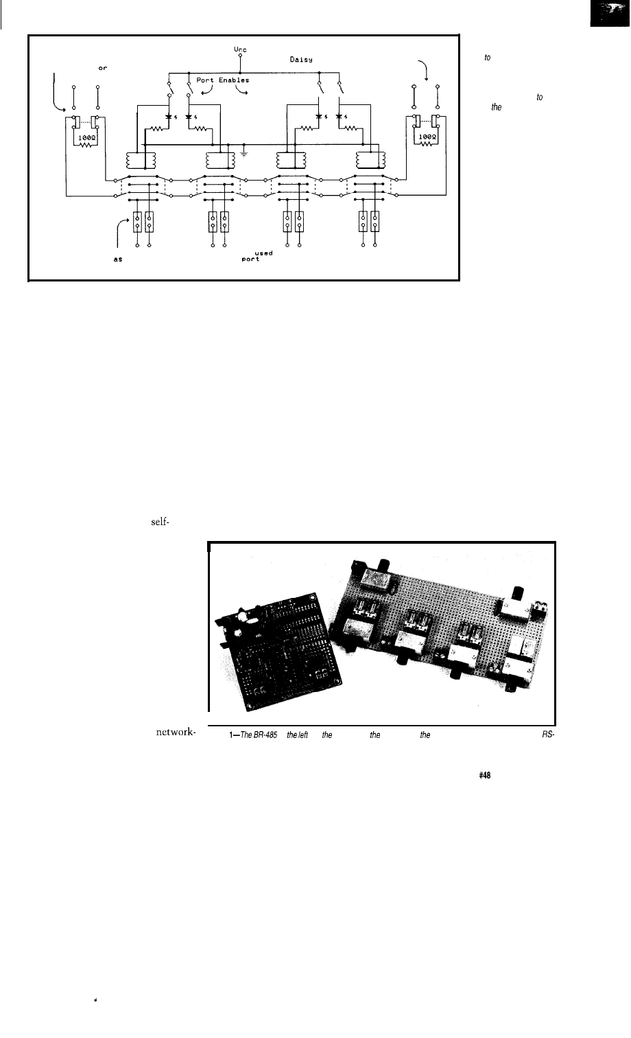
This switch selects internal
termination
daisy-chain mode
chain connection point
Shunted for normal operation or
the connection points for
options
Figure l--The
Star-485 is a
simple switching arrange-
ment extend RS-485
networks and isolate portions
of the net. Semiconductor
enthusiasts can subsfifufe
silicon-based switches
rep/ace relays if desired.
accepted solution for data transmis-
sion, the industry recognized the need
for a standard. EIA standard RS-422-A
defines a differential system that
supports a single driver and up to ten
receivers on the “bus.” This specifica-
tion defines the maximum end-to-end
distance of the cable as 4000 feet and
also defines the performance param-
eters of receivers and transmitters.
driver must provide internal
The EIA RS-422-A standard was
improved with the RS-485 standard in
1983. This standard allows up to 32
receivers/transceivers to reside on a
single bus. Since there can be multiple
driver/receiver pairs present on the
bus, the devices must be designed to
handle that situation. An RS-485
RS-485 uses a bus-oriented connection
method. While the bus topology helps
keep costs low, it can be a great
detriment in certain conditions.
One weakness occurs when a
cable break occurs somewhere in the
bus, effectively killing the network.
The network ceases to function
because it is broken into two incom-
plete networks, and nodes on different
sides of the break can no longer
communicate with one another.
The second case where a bus
Depending on the geographic size
of the network and the accessibility of
the network segments (the cable
installed between adjacent nodes),
troubleshooting this kind of failure can
take a significant amount of time.
topology falls short is in the ability to
troubleshoot network nodes. In the
case where one or more devices on the
network are failing (jabbering or
contributing to network collisions),
each node on the network must be
investigated to determine if it was one
of the failing elements. You might
have to power down each node or
remove its network connections and
then determine if the problem disap-
pears. This must be done for each
station on the network until the
problem is found.
This process can also be time
consuming because each node must be
visited. The best you can hope for is
that each node is easily accessible. The
fact that the network is down for the
protection against the possibility of
contention, which is defined as the
state
when more than one transmitter
is attempting to drive the bus.
The standard specifies no more
than 32
unit loads
(a unit load is
defined as a single driver/receiver pair)
be present on the bus. In a similar
manner, the physical geography of the
network must not be exceeded because
‘485 drivers are designed to operate
with a characteristic load presented by
the maximum allowable cable length
specified by the standard.
THAT’S GREAT! ISN’T IT?
I
The shortcomings of this
Photo
on and Star-485 on right provide means for extending and configuring
ing method are related to the fact that
485 nefworks.
The Computer Applications Journal
Issue
July 1994
4 1

real mode
80386 protected mode
family
R3000,
HD64180
Features
Full-featured, compact
kernel with fast
interrupt response
Preemptive, priority based task
scheduler with optional time
slicing
Mailbox, semaphore, resource,
event, list, buffer and memory
managers
Configuration Builder utility
eases system construction
Debug Tool is available
to view system internals and
gather task execution statistics
Supports inexpensive PC-hosted
development tools
Comprehensive, crystal clear
documentation
No-hidden-charges site license
Source code included
Reliability field-proven since 1980
Count
on
Setting real-time standards
since
J 978.
For a
Demo
and your copy
excellent
contact
Phone (604) 734-2 796
Fax: (604) 734-8114
KADAK Products Ltd.
206 1847
West Broadway
Vancouver,
Canada
Figure
485 networks are
severely
limited
in
howtheymaybe
wired. Using
the
Star-485
expands fhe possibilities.
RS-485 Now
N
Central Closet
Local Cluster
Network after Star 485
duration
of the
troubleshooting session
can have a major impact on those sites
where
the RS-485 network is used for
mission-critical tasks.
Another area where the bus
topology falls a short is in adding new
nodes to the network. If you need to
place a new node on the net, where
does it go? Does it get tacked on to the
end of the network! You can either
extend the network to reach this new
node or you can break the network at
the closest segment and install the
new node in the segment between two
previously existing nodes. Hopefully,
your mental map or cable management
diagrams are accurate. In any case,
network additions can be somewhat
troublesome.
LEARNING BY EXAMPLE
The Ethernet community made
wide use of bus architectures in the
early evolution of this networking
standard. As these networks grew, the
effort required to maintain, expand,
and repair them became more prob-
lematic. The Ethernet community
realized that these failures could cause
a network to be pitched right out the
of building, so they addressed the issue
by providing for a new topology. They
modified the standard to allow for a
star
topology.
There are two fundamental ways
that networks grow. One is in number
of devices attached to the network.
The other is they get larger in a
geographic sense. In either case, you
will eventually push the limits of the
network’s specifications (number of
devices or maximum allowable size).
But you may be able to apply one of
the devices presented here to get you
out of the jamb.
ENTER THE STAR-485
The Star-485 allows an RS-485
network to be configured as a star. The
method used to perform this is to “can
the bus,” meaning the bus is contained
in a modular unit. Nodes join the
network by connecting to ports on the
Star-485. This connection method
creates a star.
The star topology provides many
The schematic for the BR-485 is
benefits to the persons who have to
shown in Figure 1. What happens at
manage or repair networks. A key
the ports defines the way the Star-485
benefit provided by the star topology is
that it simplifies troubleshooting the
network. Other benefits of the star are
that it eases cable management and
network expansion.
WATCH ME GROW
What do networks do? Well,
mostly three things. The first is they
move data around-day in and day out.
The second is they break. The third is
they grow, and they grow, and they
grow.
42
Issue
July 1994
The Computer Applications Journal
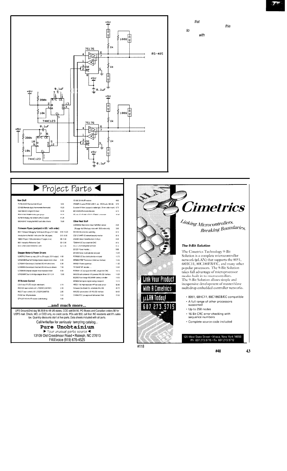
T o
N e t w o r k
T o R S - 4 8 5
N e t w o r k
Figure 3-An adaptation of
a circuit originally designed
by Mitchell Lee
appeared in the February 1994
issue of Linear Technology magazine,
version is
designed operate at 9600 bps and is published here
in its adapted form
fheir permission.
works. When the port is disabled, the
network bus bypasses the connection
to the world outside that port. This
isolates the port from whatever is
connected at that port, and likewise
isolates the network from whatever is
connected at that port. When the port
is enabled, the path the bus takes past
that port is diverted and the port (and
whatever is connected to that port) is
now a member of the bus. The two
termination resistors at either end of
the bus are there to complete the LAN
in the can, and they can be switched
out to extend the network beyond the
confines of a single hub.
Each node home-runs back to a
central location. This location pro-
vides an easy way to test and identify
each network segment. If a network
T
E
C
H
N
O
L
O
G
Y
The Computer Applications Journal
Issue
July 1994
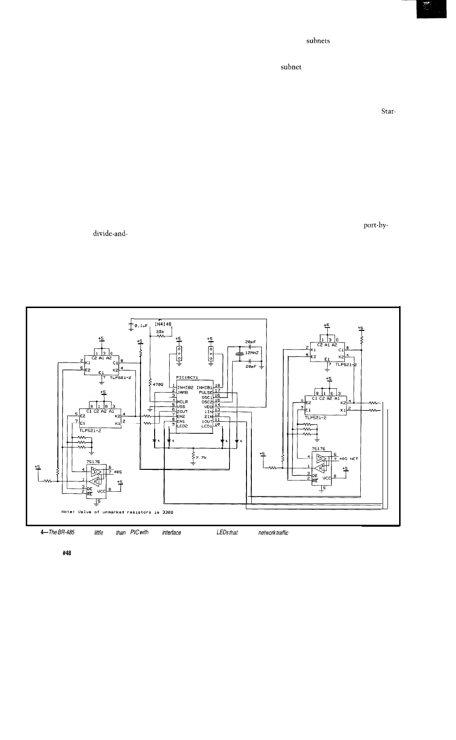
segment fails, it is easy to test the
entire physical layer of the network
from a single location. The centralized
location provides better options for
cable troubleshooting and also pro-
vides for better cable management.
Instead of having the network snaking
all around the place, it all comes back
to the Star-485, where each segment
can be clearly marked and identified.
Each network node can be
switched into or out of the network,
without having to remove a cable
connection, by a port-enable switch for
each port. This speeds up the test and
isolation of nodes that may be causing
network errors. To remove a node
from the network, disable the port the
node is connected to. When the port is
enabled, the node is part of the
network again. This design simplifies
the task of node removal and insertion
by selectively disabling and enabling
ports. This makes the
conquer approach to network repair
much easier. Figure 2 shows the
topologies possible with the Star-485.
HANDLING EXPANSION
Adding a new node to the network
couldn’t be easier. Just run the cable
between the device and the Star-485
hub and enable the port. Note that
polarity rules still apply, so make
certain the positive and negative signal
lines are connected correctly at each
end.
Each Star-485 hub can be chained
to additional hubs. This allows simple
expansion of the network by “chain-
ing” hubs to one another. Connecting
one hub to the next effectively daisy
chains the hubs. In order to enable the
chained connection, the terminator on
the chained port must be deselected.
When the terminator is disconnected
(by a slide switch), a cable installed
between hubs joins both hubs in a
single network.
The hubs may be located next to
each other for a single centralized
wiring closet or they can be distributed
in a number of wiring closets support-
ing clusters of devices in different
locations. This option connects nodes
to a hub that is closer to their location
and then runs a single connection
between hubs.
For troubleshooting purposes,
hubs can be disconnected from one
another by reselecting the terminators
in each hub. This breaks the connec-
tion between the hubs and creates
isolated
in the original
network. Remember to select the
terminators at each hub or else the
connected through the unter-
minated hub may fail because of a lack
of termination.
PORT OPTIONS
To keep entry costs low, the
485 can be configured as a completely
passive switch. The hub merely
provides the connection point for
network nodes to the bus in the hub.
Signal regeneration may be needed
for nodes that are located some
distance from the hub or when the
segment connecting the node to the
hub runs by some relatively noisy
radiation sources. To provide for this,
there are couple of designs that can be
installed in the segment at any one (or
all) of ports of the hub on a
port basis. These circuits are applied to
only the ports that require the service.
This first design is a signal
regeneration amplifier. Its purpose is
to improve the signal quality of the
network. Instead of just passing the
signal straight to the node, the signal
is passed through a nonlatching,
T
N E T
Figure
circuit is
more
a
some
chips and some
serve as
indicators.
4 4
Issue
July 1994
The Computer Applications Journal

noninverting regenerative circuit This
allows any node to be located a
considerable distance from the hub.
The schematic for the circuit that
performs this signal regeneration task
is shown in Figure 3.
used to extend the physical dimen-
sions of an RS-485 network beyond the
bounds specified by the standard. It
does this by bridging the network
segments together into a single
logical
network. Because the network still
consists of physically isolated seg-
ments, the capacitive/loading effects
that would be brought about by a
direct connection between the net-
work segments can be ignored and is
therefore not a consideration. Also,
both of the network segments can
grow to the physical size specified by
the standard without any overall
adverse effects.
HOW IT DOES IT
This circuit is “tuned” to operate
at
bps. It operates by monitoring
both of the RS-485 networks for a
start bit. When a start bit is seen on
one side or the other, the one-shot is
fired which switches the opposite
network (relative to the incoming start
bit] into transmission
mode. The duration of
the transmitter’s on time
is about 10 bit times, at
which point the one shot
expires and the circuit
resets itself.
Initialize chip
THE “BR-485” OPTION
FOR THE STAR-485
For those who want
to completely wild, you
can choose to plop in the
BR-485 (the term BR-485
is an acronym for Bridge
Repeater 485). Those of
you familiar with devices
commonly found in
speed data networks are
probably already aware of
the general function of a
bridge repeater. But for
the benefit of those of
you not familiar with
them, a short explanation
follows.
Set
up
internal data,
variables,
and flags
When the BR-485 is initialized, it
listens to both of the networks for any
traffic. If any traffic is identified, the
BR-485 checks the other network for
traffic. If traffic is found to be present
on both networks, then a collision is
taking place. In this event, no traffic is
forwarded to either network and the
“Collision LED” will light
to indicate the condition.
In the event no collision is
detected, the traffic from
one network is immedi-
ately forwarded to the
other network. Whenever
traffic is being forwarded
through the BR-485, a
“Net Bit Forwarded” LED
will light up for the
duration of the packet.
This provides a visual
indication of which
network is generating the
traffic.
Idle and
pulse
heartbeat
LED
A bridge repeater is a
simultaneous member of
two or more physically
separate networks. The
simple bridge repeater
typically will not
generate traffic of its
own. Its sole purpose is
to listen to each network,
and whenever it senses
traffic on any network, it
immediately forwards
that data to all other
networks.
Pause while
blinking
collision
indicator LED
provided for the benefit of
the user. The flowchart
for the program running in
this PIC is shown in
Figure 5.
Forward bits,
blink
and exercise
control lines
That said, the
485 is a simultaneous
member of two physi-
cally separate RS-485
networks and can be
Figure
reduced to its
essence, runs a tight loop
for
bits and then branches according/y.
If you look at Figure
4, it’s pretty apparent that
a single-chip controller (a
PIC) runs the show in the
BR-485. The rest of the
components in this device
support the I/O interfaces
for the controller or are
The pair of 75 176s are
used as the network I/O
ports. The
con-
nected to the controller
are used to provide an
indication of what the
device is doing. One of
them (connected to the
pulse output) is the
heartbeat of the system. It
toggles every time the
485 code goes through its
idle loop. Don’t count on
seeing it blink, though,
because this processor is
pretty zippy. The LED
46
issue July
1994
The Computer Applications Journal
indicators blink on for the duration of
a transmission. It is normal for these
two
to flash on and off during
normal operation. The fourth LED,
connected the JAMB output, blinks on
for a short time if a collision is sensed.
The small handful of resistors are
acting as either pull-ups or current
limiters.
NETWORK SECURITY AND
TRAFFIC CONTROL
The BR-485 contains a 2x3 header
that can be used to control the for-
warding behavior of the BR-485. For
full-duplex operation, both of the
center pins on the header will be
shunted to ground. If the center pin on
one of these headers is shunted to 5 V,
then the network controlled by that
pin will not be monitored for traffic.
This creates a simplex repeater and
traffic will only flow through the
485 in a single direction.
If both of the center pins are
shunted to 5 V, then the BR-485 enters
a “blocked” state. As long as the
485 is blocked, no traffic will be
forwarded through the device, regard-
less of which network generates
traffic. The blocking feature can be
useful for controlling access to the
network. If the center pins of these
headers are brought under the control
of an external controller, then you
have the basis of a controlled network
access system.
TYING IT ALL TOGETHER
The Star-485 serves a very useful
purpose in making RS-485 networks
easier to test, maintain, add to, and
manage. If you agree that the bus
topology has weaknesses and would
prefer to install a star topology for your
RS-485 network, then the Star-485
gives you that option. Since it uses a
modular design, its initial entry costs
are very low but it can be expanded to
support unlimited stations. Since the
hubs do not have to be located in a
single location, it is possible to create
distributed stars that would serve local
clusters of devices. Larger systems can
also be easily subnetted and the
network load can be distributed quite
easily by connecting nodes from one
hub to another.
Now, not every RS-485 network
can justify the application of a star
topology. But the idea has great merit
in those cases where the network is
large, contains many devices, or is
running a mission-critical application.
The reduction in down time is the
paramount concern in these cases and
the star helps to lessen the time the
network is down by providing an
architectural advantage.
The simple RS-485 signal regen-
erator is a low-cost way to get some
additional noise or distance margins in
an RS-485 network. It can be easily
spliced into a line wherever a signal
boost is needed.
The BR-485 can be used to solve a
wide variety of common network
problems. The simplex and
blocking modes can also be applied to
control the access to your network or
it can be used to control the way data
flows in your network. When you
consider this device in the big scheme
of things, it may not be a space
shuttle, but it is just about the smart-
est piece of wire I have seen yet.
q
Michael Swartzendruber is an engi-
neer with experience in network and
communications design and Windows
and Macintosh programming. He may
be reached at
corn.
Preprogrammed
for the
485 are available. Contact
Michael through CompuServe for
more information.
Software for this article is avail-
able from the Circuit Cellar BBS
and on Software On Disk for this
issue. Please see the end of
in this issue for
downloading and ordering
information.
410
Very Useful
411 Moderately Useful
412 Not Useful
for Microsoff C, Borland C, Borland/Turbo Pascal
Develop Real-Time Multitasking Applications under MS-DOS with
RTKernel is a professional, high-performance real-time multitasking kernel. It runs under MS-DOS or in ROM
and supports Microsoft C, Borland Ctt, Borland/Turbo Pascal, and Stony Brook Pascal+. RTKernel is a
library you can link to your application. It lets you run several C functions or Pascal procedures as parallel
tasks. RTKernel offers the following advanced features:
l
preemptive,
scheduling
l
supports up
to
36 COM ports
Hostess boards)
number of tasks only limited by available
RAM
l
supports protocols
task-switch time of approx. 6 s
486)
l
full
of
UART chip
l
performance is Independent of the number of tasks
l
supports math coprocessor and emulator
l
use up to 64 priorities to control your tasks
l
fast, inter-networkcommunication using Novell’s IPX
priorities changeable at run-time
l
runs under MS-DOS 3.0 to 6.x, DR-DOS,
l
time-slicing can be activated
or without operating system
l
programmable timer interrupt rate (0.1 to 55 ms)
l
DOS calls from several tasks without re-entrance problems
high-resolution timer for time measurement (1 s)
l
supports
multi-tasking applications
activate or suspend tasks out of interrupt handlers
l
runs Windows or DOS Extenders as a task
l
programmable interrupt priorities
l
supports
and Turbo Debugger
l
semaphores, mailboxes, and message-passing
l
Kernel Tracer for easy debugging
l
keyboard, hard disk, and floppy disk idle times
l
usable by other tasks
l
full source code available
l
interrupt handlers for keyboard, COM ports, and
l
no run-time royalties
network interrupts included with source code
l
free technical support by phone or fax
4 . 0 $ 4 9 5
$ 4 4 5
International orders: add $30 shipping and handling.
C Source Code: add $445
Pascal Source Code: add $375
Mastercard, Visa, check, bank transfer accepted.
Professional Programming Tools
In North America, please contact:
On Time Marketing
88 Christian Avenue Setauket, NY 11733 USA
Phone
689-6654
689-l 172
CompuServe 73313.3177
Outside
America, please contact:
On Time Marketing
32 20357 Hamburg GERMANY
CompuServe 100140,633
The Computer Applications Journal
Issue
July 1994
4 7
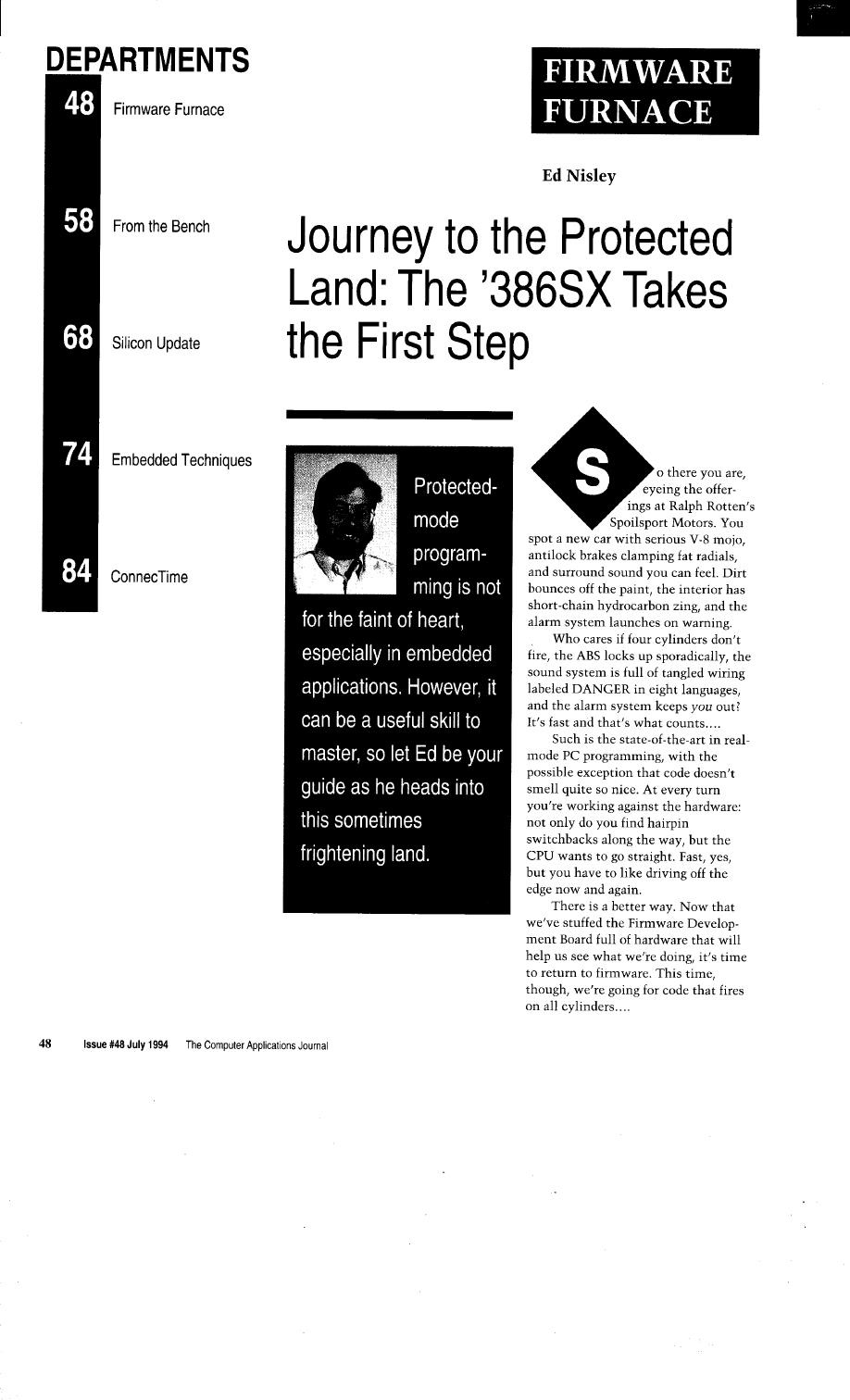
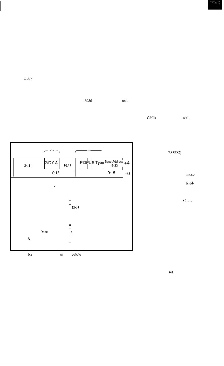
WHITHER THE PROTECTED
LAND?
With the advent of the Intel
80386EX embedded processor, this
“embedded PC” stuff suddenly starts
looking positively mainstream. Your
stock PC clone is now a bond-out CPU
emulator: all the techniques I’ve been
discussing are applicable to 386EX
programming. Those PC compatibility
barnacles have enough sticking power
to determine what the latest silicon
must look like: if it’s not precisely like
a PC, it just doesn’t survive.
The catch: we’ve been using 16
bits of a
CPU, limiting it to a
megabyte of memory address space,
and giving up lots of debugging
assistance. It’s a shame, but the
barnacles work against us as well as
the hardware folks, too.
Using the full power of the ‘386
CPU (and the ‘486 and the Pentium)
requires leaving the familiar confines
of real mode and entering the un-
charted territory of protected mode.
Suddenly segments can span 4
gigabytes, you can’t overwrite your
code (unless you try real hard), and the
CPU keeps you from stomping on data
at the end of a null pointer. It all
sounds interesting until you learn that
FAR JMP and CALL instructions can
run for hundreds of clock cycles. Well,
there are always tradeoffs.. . .
In upcoming columns, I’ll explore
those tradeoffs by writing a simple
protected mode task switcher: FFTS,
the Firmware Furnace Task Switcher.
Although it has many of the attributes
of an operating system, it’s tuned for
tinkering rather than general program-
ming. We’ll explore memory protec-
tion and paging, the CPU’s debugging
hardware, interrupt and task switching
response times, and the grubby details
you don’t find anywhere else.
One feature should pique your
interest: FFTS will use the CPU’s
Virtual
mode to multitask
mode embedded programs. We can run
the same programs we’ve been using
all along to get both protected-mode
system functions and easy-to-code
real-mode user routines. V86 programs
still have most of the disadvantages of
real mode, but at least a crash won’t
wipe out the whole system.
Attributes
Access Rights
7
3 1 3 0 2 9 2 8 2 7 2 6 2 5 2 4 2 3 2 2 2 1 2 0 1 9 1 8 1 7 1 6 1 5 1 4 1 3 1 2 1 1 1 0 9 8 7 6 5 4 3 2 1 0
Base Address
S e g L i m i t
Base Address
Segment Limit
Segment Base
32-bit starting address
Segment Limit
20-bit size 1
Segment Attributes
G
Granularity
0 = limit in bytes (1 MB)
1 limit in 4K chunks (4 GB)
D
Default op size
0 16-bit
1 =
0
Reserved
must be zero
A
Available
may be used by system firmware
Segment Access Rights
P
Present
DPL
Privilege
Seg Type
Type
0 not present in storage or invalid
1 present and valid
00 most privileged (system)
11 least privileged (user)
0 = system segment
1 code, data, or stack segment
See Figure 2
Figure l--Every
of storage accessible to
CPU in
mode must be addressed by a segment
descriptor. The
various fields specify the segment’s
attributes so the
CPU
can
verify each access; an improper
access causes a
protection exception... which is what protected mode is
all
about.
The Computer Applications Journal
issue
July 1994
4 9
As in previous columns, I’ll
proceed step by step with an eye on
the fundamentals. There will be lots of
debugging support to help isolate
problems and the overall design will be
simple enough that we don’t get lost in
the forest. Although the Firmware
Development Board’s hardware will
come in handy, it’s not absolutely
essential; you’ll be able to tweak the
code to run without it if you like.
Because this is a firmware col-
umn, you’ll continue to see scope
traces, logic analyzer records, and
timing diagrams. I’ll avoid discussing
many operating system design issues;
if you need that sort of stuff, there are
references available. Here you’ll see
what happens at the point where
firmware meets hardware-where
microseconds matter!
The folks in the local Robotics
Club are interested in FFTS because
they see it as a way to get a bunch of
virtual
running separate
mode robot control tasks. With any
luck, we can handle a bunch of sensors
and actuators with one cheap PC
system board and a little interface
hardware.
And, of course, if you’re building
an embedded system (perhaps with a
new special-purpose
you can
surely put FFTS to good use. Think of
it as the kernel for your own applica-
tion rather than an operating system
and you’ll be on the right track.
Although C++ is the current
favored language, FFTS will use
Borland’s TASM. Assembler is a
and-true part of this series and, as it
turns out, most of the code we’ll need
is better suited to assembly language
anyway. I am looking at using
C
compilers for some of the more com-
plex code later on, but we have a long
way to go before that becomes critical.
The real-mode setup code will use
the DOS versions of Borland C++ and
TASM. As before, Paradigm’s Locate
will convert the whole affair to a
binary file compatible with the custom
disk boot loader.
A WHOLE NEW CPU
Each of the books in the “Reading
Assignment” section at the end of this
column devotes several chapters (in
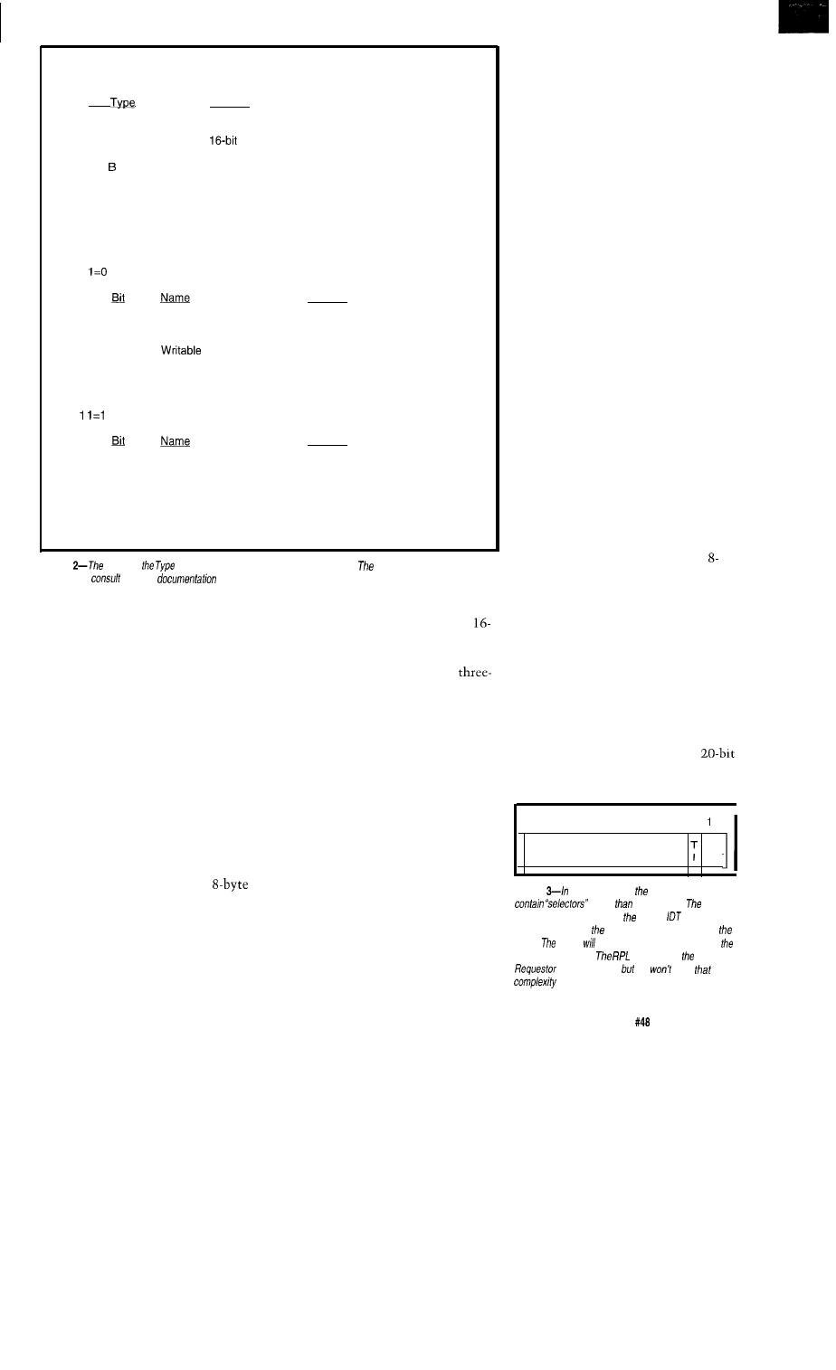
a) S=O
defines a System Segment. When S=O the Type field is a binary number
identifying the segment. These values are the most useful ones for 32-bit programs:
Seg
Meaning
2
Local Descriptor Table
5
Task Gate
6
interrupt Gate
9
32-bit Task State Segment, not busy
32-bit Task State Segment, busy
C
32-bit Call Gate
E
32-bit Interrupt Gate
F
32-bit Trap Gate
b) S=l defines a code, data, or stack segment. When S=l the Type field is bitmapped
with these meanings:
Bit 1
defines a data or stack segment:
Meaning
11
Executable
0 = data segment
10
Expansion Direction
O=expand up
1 = expand down
9
0 = Read-only
1 = Read/Write
8
Accessed
0 = descriptor not used or tested
1 = set when used by CPU
Bit
defines a code segment:
Meaning
11
Executable
1 = data segment
10
Conforming
0 = normal privilege applies
1 = execute at caller’s privilege
9
Readable
0 = Execute-only
1 = Execute/Read
8
Accessed
0 = descriptor not used or tested
1 = set when used by CPU
Figure
S bit and
field define a bewildering variety of segments.
more common values are
shown here;
fhe CPU
for further details.
some cases, the entire book!) to
explaining how
‘386
protected mode
works. For now I’m going to point out
just the brightest highlights before
diving into the code. In future col-
umns, I’ll get into more details, but
you’d be well advised to pick up a
few books that have the tables and
charts.
The key to understanding pro-
tected-mode programming is what’s
called a segment descriptor. Every
memory address, every FAR J M P and
CA L L, every interrupt handler, every
task is associated with a descriptor. If
it’s not in a descriptor, you not only
can’t use it, you can’t even see it.
A descriptor is simply the
memory structure shown in Figure
1.
The S bit and Segment Type field
specify the descriptor type and control
the meaning of the other fields.
Although you’d like to have contigu-
ous address and limit fields, the
barnacles prevent it: ‘386 descriptors
are backward compatible with the
bit descriptors found in the ‘286, so the
extra bits just didn’t fit very neatly.
Everybody gets to unscramble a
part address field and a two-part limit
field just to maintain compatibility
with an obsolete CPU.
In fact, the LSL (Load Segment
Limit) instruction “loads a register
with an unscrambled segment limit”
so you don’t have to write code to
figure it out. CISC to the rescue!
Descriptors fall into two broad
classes: system and segment. When
the S bit is 0, denoting a system
segment, the descriptor contains
information about tasks, interrupt
handlers, call gates, and suchlike.
When the S bit is
1,
the descriptor
maps code, data, and stack memory
segments. Figure 2 shows the most
useful values of the Segment Type
field in each case.
The CPU uses three tables of
descriptors, each selected by a separate
CPU register: the Global Descriptor
Table, the Local Descriptor Table, and
the Interrupt Descriptor Table. While
you can build descriptors outside these
three tables, the CPU can’t make use
of them. It bears repeating: if the thing
you want to use isn’t covered by a
descriptor in the appropriate table, the
CPU cannot access it.
The GDT holds system and
memory descriptors that are available
throughout the system. The first entry
is particularly important: it must be
filled with zeros because it represents
the null pointer. Any attempt to
reference storage with that descriptor
causes a protection exception.
When we start multitasking you’ll
see that each task can also have a
separate LDT defining its memory and
routines. LDT descriptors are available
only to a single task, but each task can
also access memory and routines
shared with other tasks through the
GDT. For the moment, though, we
won’t use LDT descriptors.
The IDT corresponds to the
familiar real-mode interrupt vectors
starting at address OOOO:OOOO. In
protected mode, the “vectors” are
byte system descriptors that transfer
control to the appropriate interrupt
handler. If an IDT descriptor is invalid,
the CPU will invoke an exception
handler rather than simply leap into
hyperspace. Of course, it’s your
responsibility to make the descriptors
correct; if you put a bad address in the
descriptor, you still get what you
deserve.
In real mode, the segment regis-
ters hold the upper 16 bits of the
physical address. In protected mode,
they hold a number, called a
selector,
15 14 13 12 11 10 9 8 7 6 5 4 3 2
0
Table Index
RPL
Figure
protected mode, segmenf registers
rather
address bits.
Jab/e
Indicator
bit selects either GDJ or
and fhe index
field selects one of 8K descriptor entries (hence
name).
CPU cause a protection
exception if
descriptor is invalid.
bits indicate
Privilege Level, we
need
for awhile.
The Computer Applications Journal
Issue
July 1994
51
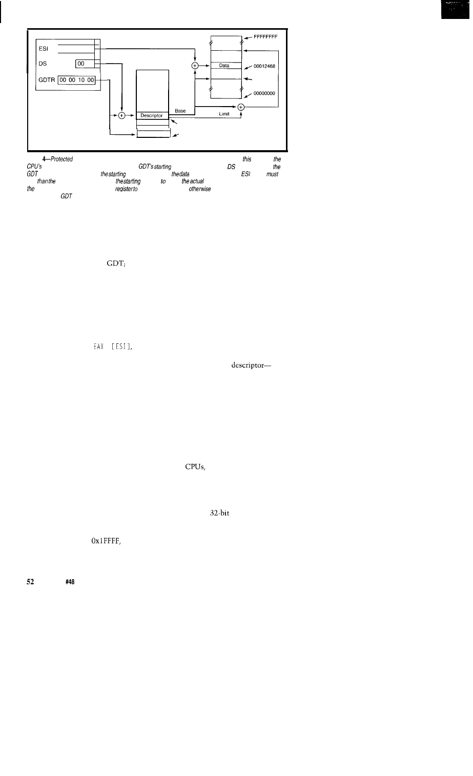
00 00 24 68
18
00010000
386 CPU
00001018
00001000
GDT
Figure
mode memory addressing uses far more CPU hardware than real mode. In
example,
Global Descriptor Table Register holds fhe
address. The selector in identifies one of
descriptors, which contains
address and size of
segment. The offset in
(which
be
less
segment size) is added fo
address create
memory address. The CPU holds
descriptor information in an infernal
improve performance;
each memory access would
require several
accesses.
that identifies a descriptor in either
the GDT or LDT. Figure 3 shows the
selector layout: the high-order 12 bits
are an index into the GDT or IDT
(which are thus limited to 8192 entries
or 64K bytes maximum). If bit 2 is 0,
the selector refers to the
if it’s 1,
the CPU uses the current LDT.
The remaining two bits contain
the requester privilege level, which I’ll
get into much later on. For now,
suffice it to say that we’ll give our-
selves “most privileged” status and try
to stay out of trouble.
Figure 4 shows how this works for
the instruction MOV
,
which implicitly refers to segment
register DS. In this example, DS holds
0x0018, which corresponds to entry 3
in the GDT. The GDT Register points
to the start of the GDT at 0x00001000.
Adding that value to DS produces the
descriptor’s memory address:
0x00001018.
The CPU fetched that descriptor
from the GDT when a previous
instruction loaded DS. All eight bytes
of the descriptor remain in an internal
CPU cache register so successive
instructions don’t reread the GDT. If
you change the GDT, you must also
reload the selectors to update the
corresponding descriptor cache entries.
The CPU compares the offset in
ESI, which we’ll assume is
0x00002468, against the descriptor’s
limit field, which is
to verify
that it lies within the segment. If not,
the CPU causes a general protection
exception to prevent an invalid
memory access; you can’t read or write
beyond the end of a segment anymore.
Because the descriptor limit field
has only 20 bits, the largest segment
seems to be 1 MB. Although that’s
better than 64 KB, it’s not really
enough. The descriptor’s G bit controls
the “granularity” of the segment limit:
when G = 1 the limit field has units of
4096 bytes (0x1000) and the maximum
segment can be 4 GB long. Conversely,
the smallest G = 1 segment is 4 KB, so
you should set that bit only when you
need it.
If the offset lies within the
segment, the CPU adds the segment
base address from the
0x00010000-to the contents of ESI.
The result-0x00012468-is called the
linear memory address.
Later on we’ll activate the ‘386
CPU’s paging mechanism, which
translates linear addresses into the
physical addresses that actually go out
on the address bus. For now, paging is
disabled and linear addresses are
identical to physical addresses. For
‘386SX
you must ensure that all
physical addresses fall in the first 16
MB of memory because the chip has
only 24 address lines.
Finally, the CPU fetches the
contents of the
word at
0x00012468 from memory and loads it
into EAX. As far as the program is
concerned, it’s a single instruction just
like in real mode.
Whew!
Believe it or not, that whole
process takes the same four clock
cycles it does in real mode. The ‘386
includes quite a bit of extra hardware
to compute protected mode addresses
quickly. The ‘486 brings even more
hardware to bear and fetches the value
in a single cycle.
Now you can see what’s so
protected about protected mode.
Among other things, the DS selector
must be valid, the descriptor must
define a readable data segment, and the
offset must lie within the segment.
The CPU will cause a protection
exception if any of the myriad checks
detects an inconsistency.
For example, you cannot load a
nonreadable code segment descriptor
into DS, let alone overwrite the code.
You cannot load a data segment
descriptor into CS, so you can’t
execute data. If you fill the unused
GDT entries with invalid descriptors,
the simple act of loading a wild pointer
causes a protection exception. If that
pointer happens to refer to a valid
descriptor, you’ll get a protection
exception when you try to read or
write beyond the segment limit. Yes,
you can still clobber yourself, but you
have to work harder at it.
There’s more to protected mode
than that, but, as Lao Tzu put it, “A
journey of a thousand miles must
begin with the first step.” Here we
go....
WATCH THAT FIRST STEP!
The 80386 CPU emerges from
hardware reset in real mode. Although
the barnacles dictate that it must look
like a fast 8086 (so it can run all that
obsolete code!), the fundamental
justification for real mode is that you
can’t enter protected mode until you
prepare [at least) the GDT and IDT.
Until those tables are valid, switching
to protected mode will cause an
immediate error.
In fact, because the error occurs in
protected mode, the CPU will attempt
to vector to the appropriate error
handler through the IDT. The IDT is
invalid, so the CPU will attempt to
vector to the double-fault handler,
which is also in the IDT and equally
invalid. The CPU, operating on the
issue
July 1994
The Computer Applications Journal
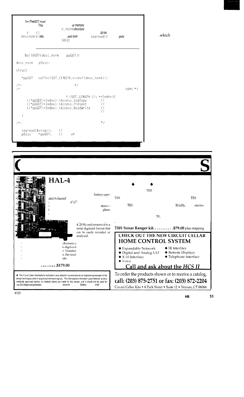
Listing
be created by a program running in real
mode, so we can use ordinary
embedded C code.
routine
allocates a block
on the near heap and fills in the descriptors
required by the B/OS function. The des
maps the fields shown in Figure 1. The
Ma k e L n e a r function converts a real-mode far pointer info a linear
address, while
Set
the various address
fields. The
function
fhe real
mode segment register values into the
structure so the code can translate them into the
corresponding protected mode segment base addresses.
int
**
*
int Index:
SREGS sregs;
=
fill in the default fields
skip NULL and BIOS CS entries, as required by the BIOS
for (Index = 1; Index
= 1;
code/data/stack
= 1;
always present
= 1; data=writable,
code=readable
fill in the table entries
get current seg regs
==
aim the GDT starting address
(continued)
“three faults and you’re out” principle,
enters shutdown mode. The PC
system board responds to CPU
shutdown with a hardware
reset..
starts the cycle over
again.
The ‘386 manuals cover the
intricate dance needed to activate
protected mode when your code is
running on a bare system. In our case,
however, there’s an easier way: BIOS
Int
15,
AH=89 is the Official “Switch
to Protected Mode” function. You
prepare a GDT with a few specific
descriptors, aim the IDT at your
exception handlers, invoke the BIOS
function, and it returns control to you
with the CPU in protected mode.
The motivation for using the BIOS
function is the same as always:
manufacturers (presumably) invest a
great deal of effort encrusting their
system BIOS code with compatibility
barnacles. No matter what oddness
lies at the hardware level, you can be
reasonably sure the BIOS will set
things up so the CPU works correctly
after the mode switch.
31RCUIT CELLAR KIT
Sonar
Ranging Experimenter’s Kit
EEG Biofeedback Brainwave Analyzer
Targeting Ranging Machine Vision
The Circuit Cellar
Ultrasonic Sonar Ranger is based
on the
The HAL-4 kit is a complete
sonar ranging circuitry from the Polaroid SX-70 camera system. The
electroencephalograph (EEG) which
and the original SX-70 have similar performance but the
Sonar
measures a mere
HAL is sensitive enough
Ranger requires far less support circuitry and interface hardware.
to even distinguish different conscious
The
ranging kit consists of a Polaroid
300-V
between concentrated mental activity and
static transducer and ultrasonic ranging electronics board made by Texas
ant daydreaming. HAL gathers all relevent alpha,
Instruments. Sonar Ranger measures ranges of 1.2 inches to 35 feet, has a
beta, and theta brainwave
TTL output when operated on
and easily connects to a parallel
signals within the range of
printer port.
HAL’s operation is
straightforward. It samples four
f analog brainwave data 64
times per second and transmits th
data serially to a PC at 4800
bps. There, using a Fast Fourie
m to determine frequency,
amplitude, and phase component
ts are graphically displayed
in real time for each side of the br
H A L - 4
kit.
plus shipping
Furthermore, safe use
that HAL be
operated
The Computer Applications Journal
Issue
July 1994
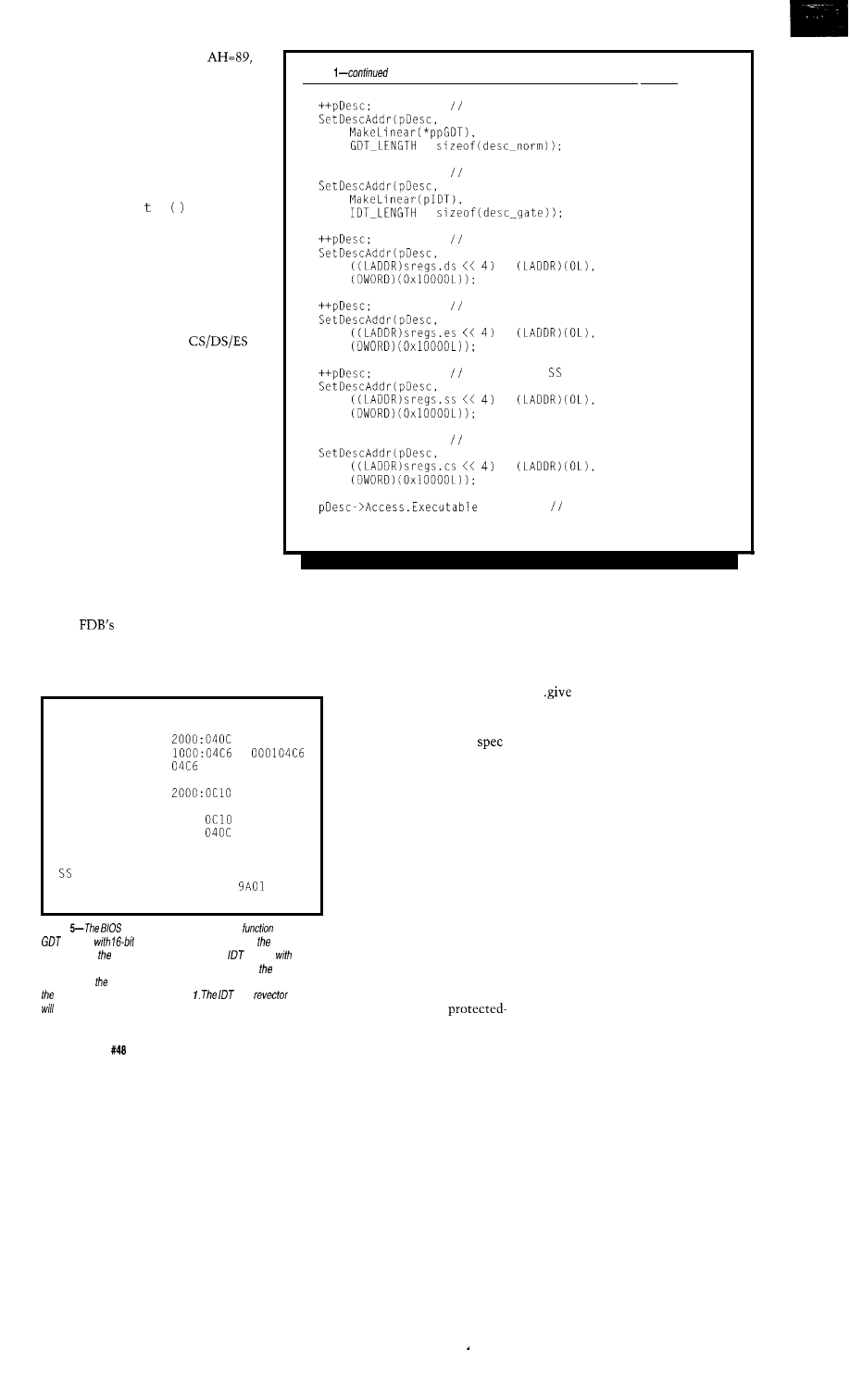
The barnacles on Int 15,
date back to the Original IBM AT, so
the GDT must be compatible with an
80286 CPU rather than the 80386
we’re using. This is no problem, but it
would help if the references mentioned
this. They don’t. Trust me. I’ve looked.
Listing
step to the GDT alias
*
Listing 1 shows the code that
creates the GDT structure. I’ve
removed the p r i n f statements to
save some space, but the complete
code (available on the BBS) produces
the display shown in Figure 5.
++pDesc;
step to the IDT alias
*
step to the DS descriptor
Compare the GDT values shown
in Figure 5 with the descriptor struc-
ture shown in Figure
1.
The descrip-
tors are listed in 16-bit format with the
low-order word first. The
descriptor limits are all FFFF and the
base addresses match up with the
values created by the Locate utility.
+
step to the ES descriptor
+
step to the descriptor
The GDT and IDT alias entries
allow access to the memory holding
those tables as ordinary data. Remem-
ber that you cannot access memory
without a valid data segment descrip-
tor: if you want to change the GDT or
IDT, you must create a read/write data
segment descriptor for that chunk of
memory.
+
++pDesc;
step to the CS descriptor
= 1
return 0;
+
code is executable
I won’t describe the IDT structure
in this column. Basically, I created a
single handler to catch all 256 possible
Once the GDT and IDT are set up,
interrupts and show the interrupt ID
the code shown in Listing 2 handles
on the
LED display. The BIOS
the transition to protected mode. This
disables all interrupts before entering
function will not return to the caller
protected mode, so the handler will
because Borland C just doesn’t expect
not get control if everything works.
to run in protected mode. We’ll have
mode operating system. After you’ve
checked out some of the references
and looked through the BBS code,
though, I think you’ll feel pretty good
about watching it blink, because
there’s a lot of information behind
it..
it a shot!
Journey to the Protected Land... Step 1
Allocating IDT at
Re-vector table
=
First IDT entry
0030 8600 0000
Second
04CE 0030 8600 0000
Allocating GDT at
GDT NULL
0000 0000 0000 0000
GDT alias
003F
9202 0000
IDT alias
07FF
9202 0000
DS
FFFF 0000 9202 0000
ES
FFFF 0000 9202 0000
FFFF 0000 9202 0000
CS
FFFF 0000
0000
BIOS CS
0000 0000 0000 0000
Figure
“Switch to Protected Mode”
requires a
loaded
segment descriptors mapping same
addresses as real mode segments and an
loaded
inferrupf handler descriptors. This screen dump shows
settings
produced by sample code this
month. Compare these fields with
descriptor format shown in Figure
and
fable
be
covered in upcoming columns.
to
get those V86 tasks
running before real-mode C
works again.
Although the BIOS
says the function will return
with the carry flag set on
error, my experience has
been that any failures occur
on the protected mode side
of the border and result in
protection exceptions. If you
find the system rebooting,
it’s an indication that it
entered protected mode with
an invalid IDT that prevents
the error handler from
gaining control.
Blinking an LED may
not sound like much com-
pared to running a
STEPS, BUGS, AND ERRATA
One advantage of a standard PC
system board is that you’re reasonably
certain the hardware works correctly.
It’s not like an R&D project where you
are part of a team inventing firmware
and hardware in parallel; locating bugs
and deciding who gets to fix them may
require weeks of hellish effort.
Real-mode programming is about
as stable as you can get because the PC
compatibility barnacles force manufac-
turers to test their hardware against
the universe of DOS applications.
With precious few exceptions, you can
do real-mode programming “by the
book” and get exactly the results you
expect.
5 4
Issue
July 1994
The Computer Applications Journal
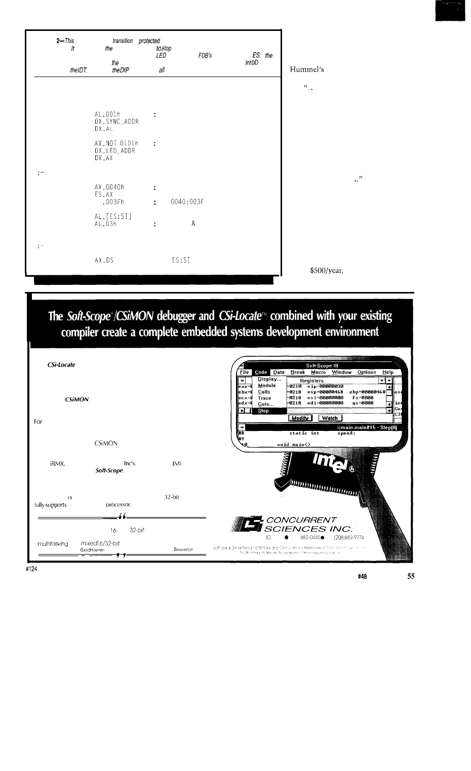
Listing
code hand/es the
to
mode and displays status outputs so you can see
what happened. must wait for floppy drive motors
because fhe timer interrupt handler isn’t valid
in protected mode. The protected mode code blinks an
and loads fhe
DIP switches info
if
bits are not a valid
GDJ
selector, CPU will
cause
a general protection failure
and
invoke the
handler through
Make sure
switches are OFF before running this code.
PROC
P M E n t r y
ARG
V e c t o r A : W O R D , V e c t o r B : W O R D
P U B L I C P M E n t r y
MOV
f l a g e n t r y h e r e
MOV
OUT
MOV
p r e s e t t h e d i g i t s t o d a s h e s
MOV
OUT
w a i t f o r d i s k e t t e m o t o r t o s t o p s p i n n i n g
MOV
a i m a t m o t o r s t a t u s
MOV
MOV
S I
a t
@ M o t o r s :
MOV
T E S T
drives A B
J N Z
@ @ M o t o r s
s e t u p t h e r e g i s t e r s
MOV
; s e t
t o G D T b a s e a d d r e s s
(continued)
In contrast, protected mode
programming is a minefield. Consider
this paragraph from the “Incompat-
ibilities and Bugs” chapter of
The Processor and Copro-
cessor:
.On some versions of the 80386,
if the operand of the VERR instruction
is not accessible and none of the
instructions following the VERR in the
prefetch queue is a JMP, CALL, or has
a memory operand, then the processor
will hang after executing the VERR.
The processor remains stopped until
an INTR, NMI, or RESET occurs. The
system timer interrupt will normally
unhang the system..
Makes you sick just to think
about it, hmm?
Many PM CPU bugs occur only in
peculiar, difficult-to-reproduce situa-
tions. If you are writing for a particular
CPU, you can tailor your code around
hardware problems if you know what
they are. Slater’s Microprocessor
Report is famous for printing bug lists,
but at
you need real justi-
fication to put it on your reading list.
Absolute or Hex files
New
builds absolutely located files or hex files from applications
compiled using Microsoft, Borland, or Watcom tools. Soft-Scope also
supports Intel, Metaware, and Symantec tools.
Easy Configuration
Configure a
ROM monitor in minutes for most targets.
Versa tile
the entire 8086 family
of
processors, in real or protected mode.
Cost effective
Include the
royalty-free
ROM
monitor as part of your product.
Real-time support
Intel’s
Industrial Programming
MTOS-UX and
Software Systems,
C Executive fully support
Established
Concurrent Sciences developed the original source-levei debugger for the 8086 processor in 1983,
and is known known industry-wide as the expert in
protected-mode development. Soft-Scope
the Intel386 EX
We have about 750,000 lines
of source code in our product,
running on an 80486 in
both
and
protected mode, and
we are very pleased with how well Soft-Scope deals with
PO Box
9666 Moscow 83843 (238)
FAX
and
code.
Integrated Measurement Systems.
OR
The
Computer Applications Journal
Issue
July 1994
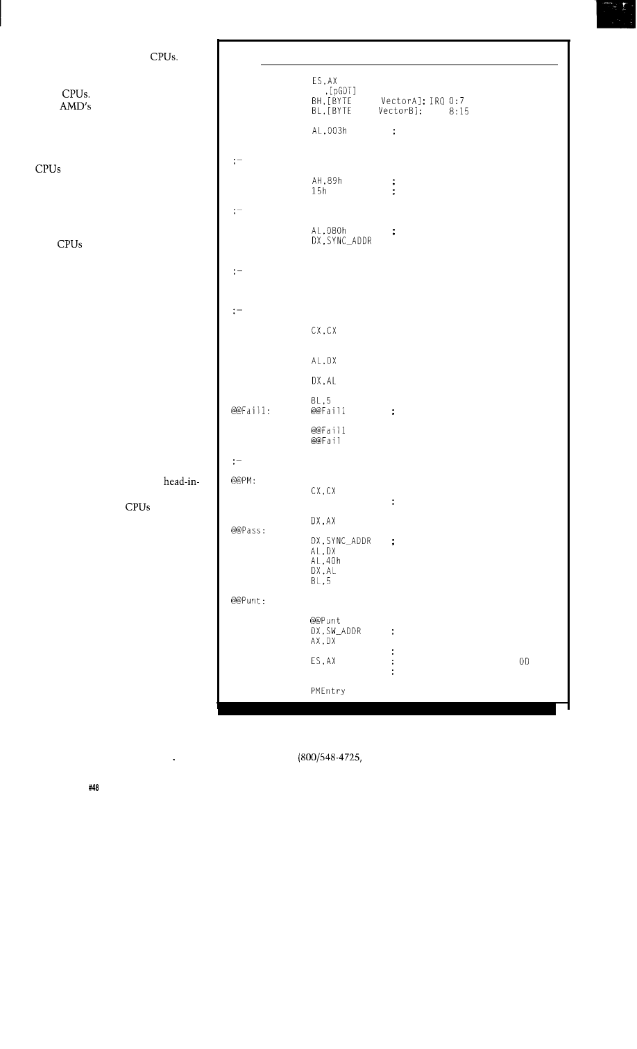
Just to make things worse, the bug
lists I’ve seen are for Intel
Most
‘386SX PC system boards, including
the one I’m using for this series, sport
AMD
I tried to get errata lists
from
Tech Support line to no
avail; unless you’re a Big Customer,
there’s not much information avail-
able.
As with all manufactured items,
are continually changed to
improve manufacturing yield, fix bugs
(really!), and take advantage of new
processes. Each chip revision, called a
“step” (at least by Intel), has its own
collection of glitches. The ‘386 and
later
load their chip ID and
revision number into DX as part of the
hardware reset. There’s a new Pentium
instruction to get those values without
having to jump through hoops, but
that doesn’t help us here.
(Hint: the Worst Hack leaves EDX
unchanged. If you really want those
numbers you can get them. Just don’t
blame me, OK?)
Even if I could identify the
company, CPU, and revision level, I
can’t code workarounds for all possible
problems and be sure they actually
work. Not only do I lack a slave labor
pool, I don’t have every PC clone ever
made on the shelf ready for testing.
Solving the general case seems
impossible. I’m going to write PM
code “by the book” using the
the-sand assumption that we’re all
using relatively new
free from
the nasty old bugs. Please send me a
note if you know of any nasty new
bugs.
FFTS will include debugging
support to identify problems as they
crop up, which is surely more valuable
than an easily outdated bug list. As
you should know by now, nearly all
bugs are in the software anyway!
READING ASSIGNMENT
We are now leaving the applica-
tions programming world behind.
Most of the popular bookstore refer-
ences dismiss the issues we’ll encoun-
ter by noting that only “systems
programmers” must worry about
them. Well, OK, if you don’t want to
Listing 2-continued
MOV
MOV
SI
MOV
PTR
MOV
PTR
IRQ
MOV
mark start of BIOS function
OUT
DX,AL
real mode
MOV
INT
protected mode?
BIOS function
make the transition
MOV
mark just after the function
MOV
OUT
DX,AL
decide what mode we're in
JNC
@ P M
still in real mode, so flag the failure
XOR
MOV
DX,SYNC_ADDR
@@Fail:
IN
NOT AL
OUT
MOV
LOOP
DEC
BL
JNZ
JMP
protected mode!
XOR
MOV
DX,LED_ADDR
MOV
AX,NOT 6767h
OUT
MOV
IN
XOR
OUT
MOV
LOOP
DEC
JNZ
MOV
IN
NOT
MOV
@ P u n t
BL
AX
JMP
ENDP
@@Pass
; by blinking the whole port
delay for a while
; initialize the delay counter
show a couple of Ps
blink bit 6 on the parallel port
; delay for a while
check switches to blow up
. . . ON = 1
GP fault = 13 decimal = hex
if AX is not valid selector
Intel, of course, has the definitive
Box 7641, Mt. Prospect, IL 60056-7641)
know how the machinery works, don’t
80x86 CPU documentation and their
is the place to get it. They’ll send you
pay any attention to this stuff..
Literature Hotline
P.O.
a catalog
(Customer Literature Guide,
56
Issue
July 1994
The Computer Applications Journal
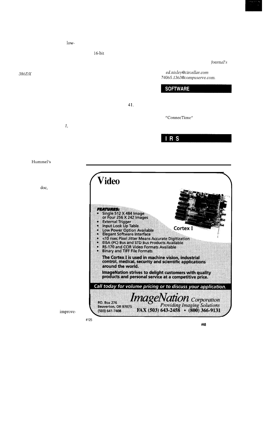
Order Number 210620-030) free, but
the rest of their books cost real money
plus 15% shipping.
80386 System Software Writer’s
Guide, Order Number 23 1499-00 1,
$18.00.
This covers the grubby
level details required to bolt a pro-
tected-mode operating system onto a
‘386 CPU. It has a wealth of “Oh, so
that’s what they meant!” info-nuggets.
Not to be missed.
Microprocessor Program-
mer’s Reference Manual, Order
Number 230985003, $25.95. This
covers both applications and systems
programming, but with a different
slant than the System Software
Writer’s Guide. Get both of ‘em. You
can also get the 386SX manual, but it’s
essentially the same as the 386DX for
our purposes.
Microprocessors: Volume Order
Number 230843-011, $24.95. More
than you really want to know about
80386, 80286, and 8086 hardware.
There are also Hardware Reference
Manuals for each CPU if you need
even more detail.
Robert
The Processor
and Coprocessor remains a ready desk
reference. It covers much of the same
ground as the Intel Programmer’s
Reference, but the approach is quite
different. Intel’s
for example, says
Word Zero about bugs. Ziff-Davis
Press, ISBN l-56276-016-5, $49.95.
Although the next two books have
nothing to do with protected-mode
programming, they are valuable
nonetheless. If you write any code at
all, for any reason, read them; they’re
that good.
Steve Maguire’s Writing Solid
Code is a well-written introduction to
Microsoft’s Techniques for Developing
Bug-Free C Programs. I was pleased to
find I already use some of the tech-
niques, but he pointed out several
flaws in my thinking. Your code will
benefit, too. Microsoft Press (of
course), ISBN l-55615-551-4, $24.95.
Steve McConnell’s Code Com-
plete is a much weightier tome on “A
Practical Handbook of Software
Construction.” The chapters include
modular design, data naming conven-
tions, control flow organization,
construction tools, quality
ment, and code tuning. If it weren’t so
well-written, it’d be overwhelming.
Buy it and use it liberally. Microsoft
Press, ISBN 1-55615-484-4, $35.00.
RELEASE NOTES
The BBS code will flip your ‘386SX
into
protected mode while
toggling bits on the printer port and
FDB LED display. This is a simple
compatibility test: if it doesn’t work,
there is something badly wrong
somewhere. It may work with ‘486
systems, but I haven’t tried it.
I used Borland C and TASM with
Paradigm’s Locate to create the binary
file. You’ll also need the boot sector
loader we used in Issue
Credit to Jim White for suggesting
the catchy “Journey to the Protected
Land” series title. Peter Holtzleitner,
who regularly dials into the BBS from
Austria, sent a complete V86 monitor
program written in German with
translations of many of the comments.
Derry Bryson contributed another V86
monitor (in English!). And thanks to
all of the BBS regulars for helping me
figure out how to cover this elephan-
tine topic in a reasonable manner. Any
errors, of course, are of my own
invention.
Next month: 32 bits or bust!
q
Ed Nisley, as Nisley Micro Engineer-
ing, makes small computers do
amazing things. He’s also a member of
the Computer Applications
engineering staff. You may reach him
at
or
Software for this article is avail-
able from the Circuit Cellar BBS
and on Software On Disk for this
issue. Please see the end of
in this issue for
downloading and ordering
information.
413
Very Useful
414 Moderately Useful
415 Not Useful
Frame Grabber
l
$495 Including Software with “C” Library
l
Half Slot Card for Compact Applications
l
Real Time Imaging with Display Output
l
8 Bit (256 Gray Levels)
The Computer Applications Journal
Issue
July 1994
5 7
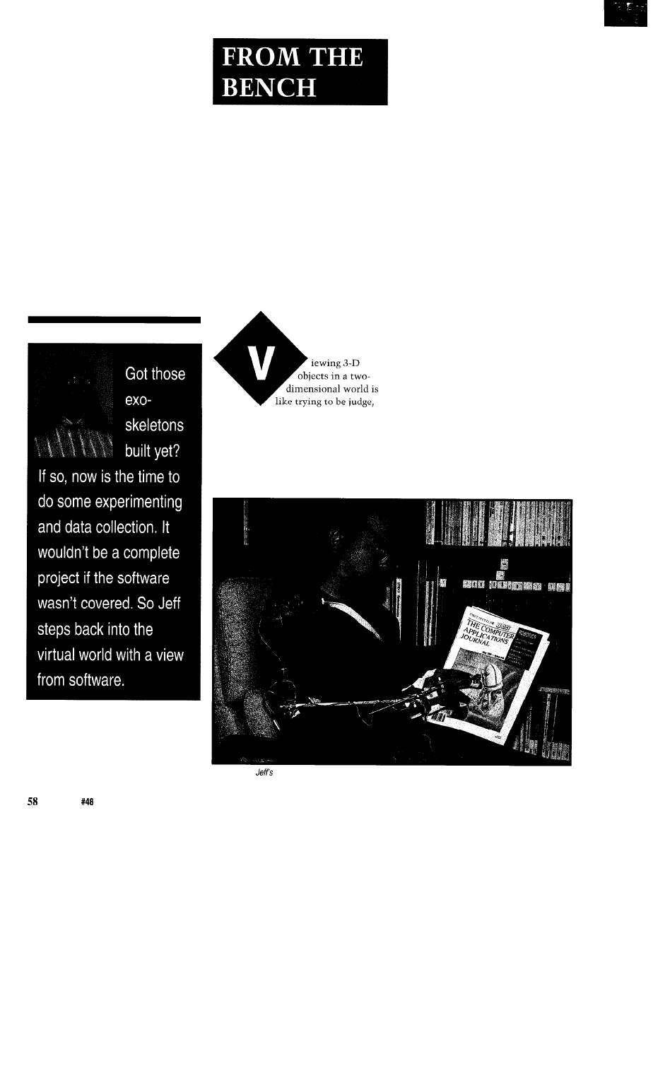
Jeff Bachiochi
Virtual Reality Requires
Real Data
Part II-A Simple Matter
of Software
ump, or referee while watching sports
on TV. What you see does not always
represent what is really happening.
You have a single point of reference on
the scene. While instant replay can
give us a different view on the scene, it
too is limited to wherever the camera
happens to be located in relationship
to the play.
In order to visually verify 3-D
movements (movements which cross
your field of vision both vertically and
horizontally, as well as move toward
and away from you), these movements
must be seen from different perspec-
tives. The most widely used perspec-
tives are top, front, and side views.
However, each of these views gives
only two sides of a three-sided story,
but the views are accurate because all
dimensions are true and not distorted
in an attempt to show depth (the third
dimension).
Most humans can see in 3-D
perspective. Our eyes, although only
inches apart, obtain two different
views. Subconsciously, through the
use of triangulation, our brain catego-
rizes each object we see by depth.
Depth is determined by the difference
in the object’s angles from each eye.
When looking at an image on a flat
screen, both eyes see the same image
and the only depth detected is how far
away the screen is, even when position
is shifted. By giving the image a bit of
(vanishing point) perspective, a feeling
of depth can be imitated.
In an effort to keep things simple,
I wanted to produce the three basic
views of my “Virtual Arm.” These
Photo l--Now
computer can keep
track of his every movement while he checks out his favorite magazine.
Issue
July 1994
The Computer Applications Journal
Listing l--The exoskeleton support
not only collects but displays if on screen. even
you
1 0
PRINT "Are you using an exoskeleton as described in
2 0
I$ =
IF
=
THEN GOT0 20
30 IF
=
OR
=
THEN REAL = 1 ELSE REAL = 0
40 IF (REAL = THEN OPEN
50
FOR RANDOM AS
CLS SCREEN 2
60 DIM
70 DIM
80 DIM
85 DIM
90 cx = -30: = 3: CL = 0: cc = 0
100 TVPX = 159: TVPZ = 50: RVPZ = 479: RVPY = 199: FVPX
FVPY = 199
110 AR = 2:
= 0:
= 90:
= 0
120
= 0:
= 1:
= 0:
= 0:
= 0:
= 40
130
= 1:
= 2:
= 0:
= 180:
= 0:
= 25
140
= 2:
= 3:
= 0:
= 0:
= 0:
= 20
150
= 3
160
= 4
170
= 5
180
= 4
= 4:
= 0:
= 0:
= 0:
= 5
= 5:
= 0:
= 0:
= 0:
= 5
= 6:
= 0:
= 0:
= 0:
= 5
= 7:
= -90:
= 0:
= 0:
= 5
= 5:
= 8:
= 0:
= 40:
= 0:
= 5
200
= 5:
= 9:
= 0:
= 20:
= 0:
= 5
159:
210
= 5:
= 10:
= 0:
= 340
= 0:
= 5
220 CONST = 3.141593 180
230 LOCATE 2, 2: PRINT "Top View (YAW Y-Axis)";
240 LOCATE 14, 2: PRINT "Front View (ROLL X-Axis)";
250 LOCATE 14, 42: PRINT "Right View (PITCH Z-Axis)"
260 LINE
LINE (639,
199):
LINE (639,
270 LINE
LINE
LINE (319,
1000 LOCATE 1, 42: PRINT "SERIAL DATA"
1010 IF REAL = 0 THEN GOT0 1030
1020 INPUT
1030 LOCATE 1, 42: PRINT "UPDATING JOINT ARRAYS": FOR Z
1040
= 0:
= 0:
= 0
1 TO 10
:
=
1050 NEXT Z
1060
=
1070
=
1080
=
1090
=
*
1100
=
*
1110
=
1120
=
1130
=
1140
=
=
1150 FOR Z = 1 TO 10
(continued)
views will show movement of the arm
from all directions at once. To syn-
chronize the “real data” from the
exoskeleton (discussed in Part
1
last
month) with this graphic virtual
representation, the data measurements
must start from some known point.
The “zeroing mode” yields a bit of
flexibility in determining the “at rest”
position. As long as both the input
device and the PC program (see Listing
1) agree, all should be happy. I chose to
use the arm hanging down at my side
with the palm back and grip open as
the “zero” or “calibration” point. This
will be the initialized position when
the program is started.
THE EXOSKELETON’S DATA
It
is essential to understand how
the data output by the exoskeleton
reflects real movements so we can
reconstruct the “Virtual Arm.” Refer
to Figure
1
and Photo 1 to identify the
position of each point (or joint) and
angle measuring sensor (potentiom-
eter).
Notice that the Z-axis is used as
the continuous and common axis
throughout the length of the body.
This simplifies the interaction be-
tween axis movements. The Virtual
Arm is constructed from lines drawn
between two points in stick figure
fashion. The points’ positions are
determined first by the program’s
initial “zero” position and thereafter
by data received from the exoskeleton.
DEFINING THE VIRTUAL WORLD
To model the arm, I chose to start
with a connection from the ground
[point 0) to the shoulder (point 1). This
simulates the body (lever
1)
from the
feet to the shoulders. The connection
from the shoulder (point 1) to elbow
(point 2) becomes lever 2 and simu-
lates the upper arm. The lower arm is
from point 2 to point 3, and the wrist
is lever 3. The hand is made up of four
main levers. The first (lever 4) is from
the wrist to the thumb joint (point
and the second (lever 5) is from the
thumb joint to the finger joint (point
5). Lever 6 represents the fingers from
the joint at point to the tip at point
6. The last lever (7) is made from the
thumb at the joint at point 4 to the tip
The Computer Applications Journal
July1994
59
at
point 7. See this illustrated in Figure
1.
Just for aesthetics, I added three
extra fingers (little, ring, and pointer).
All fingers will move together.
Every joint is represented as two
levers connected between three points.
Each joint’s position is based on the
previous joint’s position and has
(potentially) three rotational axes. The
Z-angle (pitch) is a CW (clockwise) or
CCW (counterclockwise] rotation as
viewed from the side. The X-angle
(roll) is a CW or CCW rotation as
viewed from the front. And the
angle (yaw) is a CW or CCW rotation
as viewed from the top. In reality, the
arm’s movements are limited to partial
rotation and in only particular axes
depending on the joint. This reduces
the computations from three dimen-
sions times five joints (15) down to
just eight (the number of positional
sensors being used).
The first calculations determine
the position of each joint in the
universe and are derived using a polar
coordinate system (Figure 2). This
designates the first point as the polar
origin or center of the universe. To
find the second point’s location, use
the angular directions from the last
point (in this case the polar origin)
using the X- and Y-angles (based on the
previous Z-angle-assumed to be 0 for
the first calculation) and move
outward in that direction by the length
of the body part being simulated. The
Z-angle will affect the next point’s
and Y-angles.
By placing a joint at the center of
the universe, the movement of a
second joint pivoting about the first
affects what is viewed from the three
perspectives: top, front, and side.
Viewing from the front, the
point’s “width” position is affected by
the Y-angle and the Z-angle, and the
“height” position is affected by the
angle and the Z-angle.
1) [front view width X] =
[joint X-axis point] + L( 1) [full
length of the lever] x sin(Y-angle) [or
sin(Z-angle)]
FVl?Y( 1) [front view height Y] =
[joint Y-axis point] + L(
1)
[full
length of the lever] x cos(X-angle) (or
cos(Z-angle)).
=
+
=
+
=
+
IF 4) THEN 1210
LOCATE 1 + Z, 42: PRINT Z:
INT(YAWA(Z));
NEXT Z
IF THEN GOT0 2000
FOR X = 0 TO 7
LOCATE + X, 42: PRINT "DATA": X;
NEXT X
Listing l-continued
1160
1170
1180
1190
1200
1210
1220
1230
1240
1250
2000
2010
2020
2030
2040
2050
FOR Z = 1 TO 10
=
=
=
=
=
OPY(TP(Z)) =
NEXT Z
ocx = cx:
=
= cz
3000
3010
3020
3030
3040
3050
3060
3070
3080
3090
3100
3110
3120
3130
3140
3150
3160
3170
3180
3190
3200
3210
3220
3230
3240
3250
LOCATE 1, 42: PRINT "CALC ANGLE SHIFTS SCREEN COORDINATES"
FOR Z = 1 TO 10
I$ =
IF
=
THEN GOT0 3250
IF
=
OR =
THEN D = 1
IF
=
OR =
THEN D = 0: CLS
IF (I$ = "A" OR I$ =
THEN D = 2
IF
=
OR =
THEN D = 3
IF
= "0" OR =
THEN D = 4
IF (REAL = THEN GOT0 3250
IF (I$ =
THEN
=
+
LOCATE 2, 42: PRINT
O/C
IF
=
THEN
=
LOCATE 2, 42: PRINT
O/C
IF
=
THEN
=
+
LOCATE 3, 42: PRINT
O/C
IF
=
THEN
=
LOCATE 3, 42: PRINT
O/C
IF
=
THEN
=
+
LOCATE 4, 42: PRINT
L/R
IF
=
THEN
=
LOCATE 4, 42: PRINT
L/R
IF
=
THEN
=
+
LOCATE 5, 42: PRINT
TWIST
IF
=
THEN
=
LOCATE 5, 42: PRINT
TWIST
IF
=
THEN
=
+
LOCATE 6, 42: PRINT "S-ELBOW O/C
IF
=
THEN
=
LOCATE 6, 42: PRINT
O/C
IF
=
THEN
=
+
LOCATE 7, 42: PRINT "G-SHOULDER F/B
IF
=
THEN
=
LOCATE 7, 42: PRINT
F/B
IF
=
THEN
=
+
LOCATE 8, 42: PRINT
U/D
IF
=
THEN
=
LOCATE 8, 42: PRINT
U/D
IF
=
THEN
=
+
LOCATE 9, 42: PRINT
TWIST
IF
=
THEN
=
LOCATE 9, 42: PRINT
TWIST
3260
=
+
*
*
+
*
*
(continued)
60
July
1994
The Computer Applications Journal
See the front view in Figure 3 for a
visual rendering of these ideas.
Viewing from the side, the point’s
“depth” position is affected by the
angle and the Z-angle, while the
“height” position is affected by the
angle and the Z-angle.
1)
[right view depth] =
[joint Z-axis point] +
L(1) [full
length of the lever] x cos(X-angle) (or
1) [right view height] =
[joint Y-axis point + L( 1) [full
length of the lever] x
[or
Z-angle)]
See the side view in Figure 3 for a
visual representation of the points
viewed from this perspective.
Viewing from the top, the X-axis
point’s “width” position is affected by
the Y-angle and the Z-angle, and the
“depth” position is affected by X-angle
and the Y-angle.
The
1)
[top view width] =
[joint X-axis point] + L(
1)
[full
Listing l-continued
3270
=
+
*
*
*
* 0))
3280 PITCHT(TP(Z)) =
+
3290 IF <> 2) THEN GOT0 3330
3300 LOCATE 1
Z, 42: PRINT Z:
INT(ROLLT(TP(Z)));
3310 PRINT
3320 PRINT
3330 PX(TP(Z)) =
* * COS
3340 PY(TP(Z)) =
+
3350
=
+
3360 IF (D <> 3) THEN GOT0 3380
* * L(Z))
L(Z))
* * L(Z))
3370 LOCATE 1 + Z, 42: PRINT Z;
IN
3380 NEXT Z
))
3390 IF CC = 3 THEN CX = PX(6) +
*
3400 IF CC = 3 THEN CY = PY(6) +
*
3410 IF CC = 3 THEN CL = PZ(6) +
*
3420 IF ABS(PX(7) CX) 5 AND ABS(PY(7)
ABS(PZ(7) CL) < 5 THEN CC = CC OR
3430 IF
CX) 5 AND
ABS(PZ(6) CL) < 5 THEN CC = CC OR
(PX(7)
(PY(7)
(PZ(7) PZ(6)))
CY) < 5 AND
1 ELSE CC = CC AND 2
CY) 5 AND
'2 ELSE CC = CC AND 1
4000 LOCATE 1, 42:
4010 FOR Z = 1 TO
PRINT "ERASING/REDRAWING SCREEN"
(continued)
NEW! UNIVERSAL DALLAS
DEVELOPMENT SYSTEM
from
62
It’s a complete single board computer!
One board accommodates any 40 DIP
40 SIMM
SIMM DS2252, or 72 SIMM
processor! Snap one out, snap another in.
Programs via PC serial port. Program lock & encrypt.
LCD interface, keypad decoder, RS232 serial port,
ADC, four 300
relay driver outputs.
Power with 5VDC regulated or 6-13 VDC unregulated
Large prototyping area, processor pins routed to headers
Optional enclosures, keypads,
everything you need
BCl51 Pro BASIC Compiler w/50+ Dallas keywords $399
TEL:
801.534.1017
FAX:
801.534.1019
555 South 300
City, UT, USA
84111
TW523
Interface Kits
Interface your computer to transmit and receive X-IO codes over
your AC
power line. Real-time control. Each kit contains the
X-
cable, external
connector, documen-
tation and software..
Windows Kit:
RS232, buffered,
+
source
DOS Kit:
TSR/Polling ‘C’, BASIC, PASCAL
HC2000 V2.1 TW523
Control language (DOS)
GO ONLINE FOR FREE
Complete range
X-
alarms.
VISA/MC/AMEX accepted. Volume Discounts.
Baran-Harper Group, Inc.
Orders: (800) 661-6508
Fax: (905) 471-3730
Technical: (905) 294-6473 BBS: (905)
Issue
The Computer Applications Journal
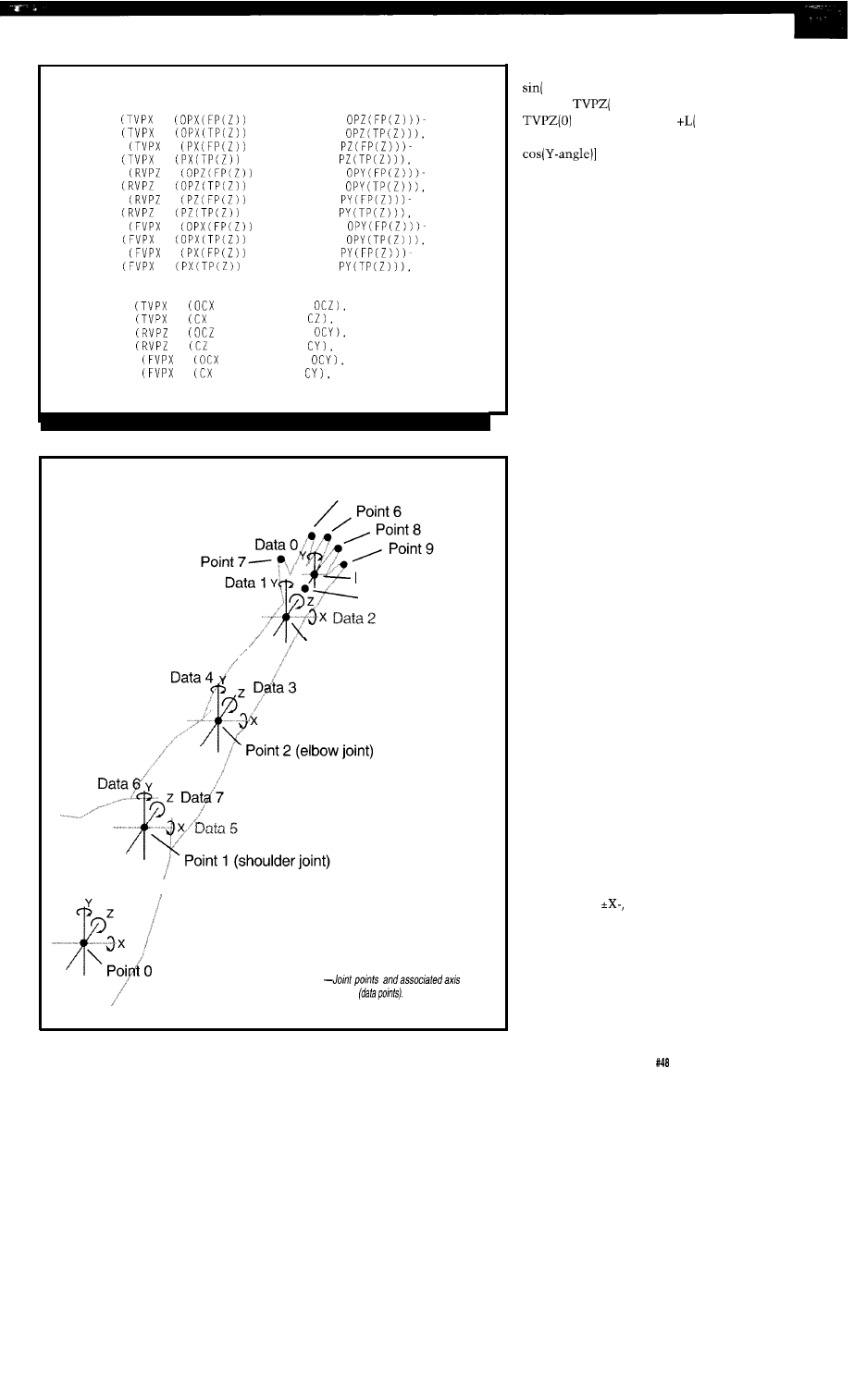
Listing
l-continued
4020
LINE
+
* AR), TVPZ
+
* AR), TVPZ
0
4030 LINE
+
* AR), TVPZ
+
* AR), TVPZ
1
4040 LINE
+
* AR), RVPY
+
* AR), RVPY
0
4050 LINE
+
* AR), RVPY
+
* AR), RVPY
1
4060 LINE
+
* AR), FVPY
+
* AR), FVPY
0
4070 LINE
+
* AR), FVPY
+
* AR), FVPY
1
4080 NEXT Z
4090 CIRCLE
+
* AR), TVPZ
5, 0
4100 CIRCLE
+
* AR), TVPZ
5, 1
4110 CIRCLE
+
* AR), RVPY
5, 0
4120 CIRCLE
+
* AR), RVPY
5, 1
4130 CIRCLE
+
* AR), FVPY
5, 0
4140 CIRCLE
+
* AR), FVPY
5, 1
4150 GOT0 230
Point 10
Point 5 (finger joint)
Point 4 (thumb joint)
Point 3 (wrist joint)
Body
Figure 1
measurements
length of the lever] x sin(Y-angle) (or
Z-angle))
The
1)
[top view depth] =
[joint Z-axis point]
1)
[full
length of the lever] x cos(X-angle) [or
See the top view in Figure 3 for
the drawing showing this point of
view.
As each new lever and joint is
added, a new point is created in the
space that is based on the present
location of the last point. The new
point’s X-, Y-, and Z-angles are relative
to all the previous points going back to
the base (center of the universe). In
this way, new points are affected only
by older points. For example, if only
the wrist joint moves, the fingers
move with the wrist, but the elbow
does not. However, if the elbow
moves, so do the wrist and fingers.
Computing a new point’s position
is based on the previous point’s
position as the base to the new
location’s relative offset direction. An
offset of 0 (on all axes) just continues
in the same direction as that of the
previous point.
Once the polar angle positions are
calculated and stored in the polar joint
array for all the joints (points), they are
converted into a linear coordinate
system so the resulting X, Y, and Z
components can be used to visualize
the new position (and relative move-
ment) on the PC screen.
The linear coordinate system
consists of three axes (as in the polar
coordinate system), but instead of
measuring each axis’s rotational angle
to the point in space, the measurement
consists of how far along the axis the
point is from the center to where the
point creates a right angle with the
axis. Each polar coordinate point
identified by an X-, Y-, and Z-angle
from the center of its universe is
converted to a linear coordinate
identified by
Y-, and Z-axis
distances from the same center of the
universe. See Figure 4.
PC PROGRAM
The PC’s BASIC program begins
with an opening of a COM port for
data reception, followed by an account
The Computer Applications Journal
Issue July 1994
63
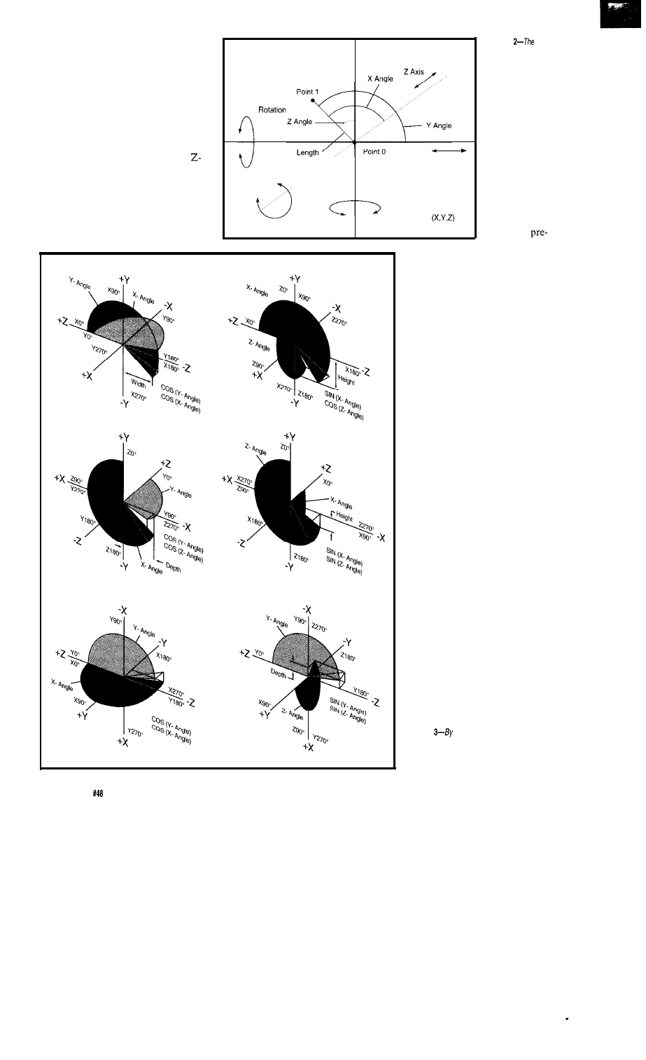
of all variables used. Included here are
the X, Y, and Z points (which are both
joints and the ends of connection
levers]. A second set of these points is
also kept: the first set describes the
new positions (for drawing) and the
second set describes the old positions
(for erasing). In addition, three sets of
X-, Y-, and Z-axis angles are kept for
each point: the original X-, Y-, and
axis angle; the joint’s present X-, Y-,
and Z-axis angle; and the total for each
axis up to this joint. Finally, two link
variables are used. These are respon-
sible for linking the X, Y, and Z points
in the right order to build the model.
As Viewed
From Side
X Axis
X Axis
Y Axis
I
Coordinate
Points
Z Axis Rotation
Y Axis Rotation
Front View
Side View
Top View
Figure
first
calculations determine the
position of each joint in fhe
universe and are derived
using a polar coordinate
system.
Each point is
defined by an array
number; all the
variables associated
with that point
have the same array
offset. Some of
these are
defined; for ex-
ample, which points will be connected
by line segments, what are the initial
X-, Y-, and Z-axis angles for each
point, and what is the length of each
line segment (body part].
The screen is put into 640x200
graphics mode and divided into four
quadrants. The upper left is labeled
“Top View,” the lower left is the
“Front View,” and right side holds the
“Right View.” The top right quadrant
is used to list items of interest (e.g.,
the eight incoming data angles
produced by the exoskeleton).
At this point, the program enters
an endless loop of collecting, comput-
ing, and displaying data. Five routines
are used for this function. The first
routine signals the external micro to
send the eight data variables and then
stores them in an array. The second
routine saves the present X, Y, and Z
points in the variables used in the
erasing routine. The third routine
updates the total axis angle (for X, Y,
and Z) for each joint from the original
starting angle, the present data angle,
and the total angles of all the previous
joints. The forth routine computes
new joint locations based on the X-,
Y-, and Z-axis angles’ totals and the
length of the line segment. Lastly, the
three old views are erased by redraw-
ing their line segments with the
background color and the new views
are drawn using the foreground color.
Figure
p/acing a joint at the center of fhe
universe, the movement of a second joint pivoting about
the first affects what is viewed from three perspectives:
front, side, and top.
64
Issue
July 1994
The Computer Applications Journal
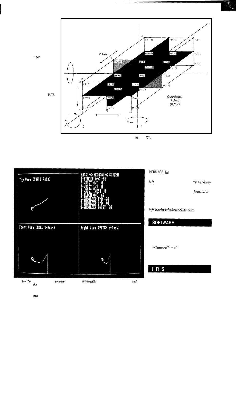
As Viewed
From Side
opening question, “Are
you using the exoskel-
eton?” with
allows
external data to be
produced using the “l-8”
X Axis Rotation
keys. Each press of a key
will increment that
Y Axis
For those of you who
have not built the
exoskeleton, I included a
routine to enter joint
movements via your
keyboard. Answering the
joint’s angle data by 10”
[holding the shift key
while pressing a number
will decrement it by
Some people won’t
consider this to be real
VR because there is
nothing in the virtual
world to react with. For
you, I’ve added a little
something extra. See
Photo 2. The arm can be
used to pick up, move,
and place a ball anywhere
X Axis
Z Axis Rotation
Y Axis Rotation
Figure 4-For simplicity, only integer points are shown. However, actual and Z coordinates can be any mixed number.
on the screen. But please be careful:
Screen updates are produced about
you can also place it off the screen. I’ve
once a second on slow machines, but
lost more balls in my monitor than I
this is based on displaying items of
care to admit.
interest as well as movement updates.
Some corners have been cut to reduce
computation times to a minimum
since this is where most of the time is
spent. If interest persists in the
exoskeleton data input system,
I
could
be coaxed into developing a driver for
Photo
exoskeleton
support
handles simple
by a//owing you fo manipulate a
on
the screen using exoskeleton device.
Bachiochi (pronounced
AH-key”) is an electrical engineer on
the Computer Applications
engineering
staff.
His background
includes product design and manufac-
turing. He may be reached at
Software for this article is avail-
able from the Circuit Cellar BBS
and on Software On Disk for this
issue. Please see the end of
in this issue for
downloading and ordering
information.
416
Very Useful
417 Moderately Useful
418 Not Useful
6 6
Issue
July 1994
The Computer Applications Journal

Babel
Buster
Tom
forthcoming “wireless
revolution.” The technology, thanks
largely to the widespread use of
“remotes” in the consumer electronics
sector, is both proven and cheap.
Yet, it’s exactly the bunny-like
proliferation of the little beasts that
gives pause. How many of you struggle
with a quiver of handhelds to manage
your entertainment center? Yes, it’s
not hard to conjure up a grim version
of the IR future.,
Tom: Hi, I’m Tom.
Bill: Glad to meet you. I’m Bill, let’s
exchange business cards.
Tom: OK. I’ll show you my PDA if you
show me yours. Ho ho!
{The carrier detect light flickers, but
won’t stay on)
Bill: Hmm, must be a problem. Let’s
move away from this window.
(They move away from the window,
and then-with the carrier detect still
flickering-perform kind of a fencing
match, each trying to aim their PDA at
the other’s “sweet spot”)
Tom: Oh,
I
know, I’m still running my
TV protocol from last night.
Bill: No sweat, I’ve got a
adapter in here somewhere.
{Bill fumbles in his briefcase to
extricate the adapter from a tangled
deck of PCMCIA cards}
TO THE RESCUE
Fortunately, there’s an compat-
ibility alliance on the horizon: The
Infrared Data Association, more
affectionately known as
The membership list is a Who’s
Who of system and silicon suppliers.
Most notably, it includes existing IR
players like HP, Apple, and Sharp who,
until now, have been promoting their
own proprietary offerings.
Now a gee-whizzy membership
list isn’t enough to guarantee a hopeful
standards success-the ash heap of
computing history is littered with a
plethora of standards hopefuls that,
although “blessed” by leading players,
still didn’t make it. Even when a
standard succeeds, it’s often a rather
tortuous process. Witness SCSI-2,
which, after many years of hem and
haw, still isn’t officially final. Consid-
ering buying one of the new “fast”
Ethernet cards? Watch out,
because there are two “standards” on
the shelf [essentially the IEEE 802
committee version and the HP version)
and they don’t talk to each other.
Maybe this time. The
members are all really true believers in
doing the “right thing,” even if it’s
their own ox getting gored. Or maybe
it’s just battle fatigue, with RISC
versus CISC, Windows versus Mac,
and the other religious wars having
taken the air (mostly hot) out of
would-be standards warriors.
Whatever the reason, it looks like
is proceeding toward a final
standard at a relatively blistering pace.
Notably missing-at least on the
surface-is the infighting, back
stabbing, and self-dealing that usually
characterizes such efforts.
So start looking for the
logo
(Figure
1)
on any gear you buy or risk
being the lonely wallflower at the IR
party.
DATA
Tom: Got it. Ain’t technology grand.
C E R T I F I E D
68
Issue
July 1994
The Computer Applications Journal
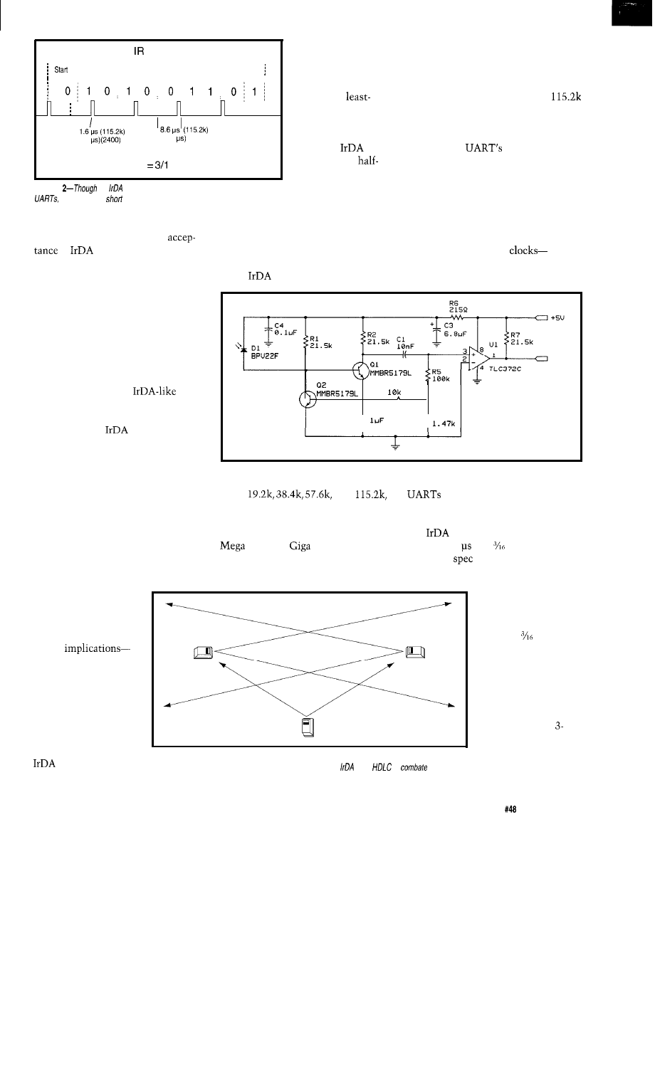
Frame
for signaling. For
The wide range (almost 50: 1) of
most of you this is old
transfer rates reflects the scope of
Data Bits
stop
bit
bit
hat by now; S-bit
devices addressed by the standard. A
characters are
data rate of 2400 bps may be all that a
transferred
tiny 4-bitter can bit bang, while
significant bit first,
is where most PCs poop out.
framed by start and
Though UART-like, there are a
(78
(416
(2400)
stop bits, and so on.
few subtleties as shown in Figure 2.
Note that
links
Notably, the
normal “level”
Pulse width
6 of bit time
are defined as
duplex (a device can
Figure
the
format is similar to that used by conventional
it instead uses
pulses to save precious battery power.
either talk or listen,
but not both at the
same time). There’s
I’M OK, UART OK
no grand strategy behind this, it’s
One factor in the smooth
simply necessary lest reflections cause
of
may be that, unlike
a device to end up talking to itself.
more grandiose efforts, the scope of the
The UART heritage is further seen
standard is strictly limited to “walk
in the
transfer rates of 2400,
up” (i.e., close-proximity, line-of-sight,
point-to-point) data transfers. It
doesn’t address the “diffuse” IR
“wireless-LAN” schemes that are
designed to bathe an entire office and
must support many-to-many commu-
nications. Lovers of chaos will find all
they need in the diffuse IR arena,
which really needs an
standards effort of its own.
output is changed to a “pulse” that
occupies only a fraction of the bit
time. Obviously, the idea is to mini-
mize the IR LED’s on time and, thus,
power consumption. In principle, this
demands more accuracy from the bit
sampling logic, but in actual practice
the accuracy of UART
typically crystal controlled-elimi-
nates the concern. Besides, most
R 3
The basic parameters-speed and
distance-of the
specification
scheme were dictated by the key
constraints of the portable equipment
+_ c 2
T
R 4
I R R X
folks, namely low cost and low power.
Thus, the distance between
transferees is limited to O-l meter,
though manufacturers can support
larger spans (e.g., up to 3 meters) at
their discretion. Interestingly, the
“zero meter” part was driven by a
human factors issue: when a transfer
Figure
3-California Wireless uses a front-end signal conditioning scheme to clean up any unwanted signals.
9600,
and
actually sample only once in
which are the usual rates supported by
the middle of the bit cell anyway, so
a PC serial port. Yeah, it doesn’t sound
why keep the LED on the entire time?
like much when everyone is hyping
defines the LED on time as
and even
goodies, but just
between
1.6
and of the bit time.
how much bandwidth do you need to
The 1.6-p
minimizes power
isn’t going well, the first thing Joe/Jane
transfer a business card anyway!
consumption, but may be too quick for
Consumer will do is
poke their gizmo right
up against the balky
recipient. As you’ll see,
this has nontrivial
design
specifically the need for
some kind of variable
threshold automatic
gain control.
Refreshingly for a
business in which NIH
always lurks nearby
waiting to pounce, the
folks adopt a
simple UART scheme
Figure
4-Without some kind of communications protocol, a scenario in which three (or more)
devices are within view of each other could cause problems.
uses
to
the
problem.
lowest-cost imple-
mentations to deal
with. They can fall
back on the more
leisurely option.
Power consump-
tion is heavily
(inverse squared law)
related to distance, a
factor behind the
minimum l-meter
and the optional
meter compromise.
However, the typical
speed/power relation-
ship doesn’t hold
The Computer Applications Journal
Issue
July 1994
6 9
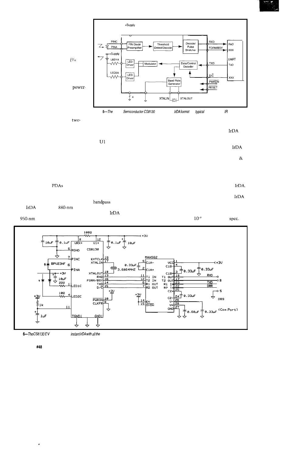
when it comes to the transfer rate. In
the case of a fixed pulse width design,
the data rate impacts only the time
between pulses, not their duration. In
other words, the total LED on-time
will be the same for a given data
transfer, whatever the data rate.
The variable pulse width
of bit
time) is even more paradoxical, in that
LED on-time for a given data transfer
will increase linearly as the inverse of
the data rate. In other words, it takes
less power to go faster. Thus, a
reducing design goal is to wring out as
many bits per second as you can.
BLINDED BY THE LIGHT
Compared to an RS-232 connec-
tion with nice thick wires and
digit voltage swing, bits hitchhiking
on photons face a much rougher ride.
Besides the fact the signal level
varies with distance and orientation,
unexpected turbulence is likely to
occur thanks to interference from a
variety of light sources that contain IR
components. Sources of interference
include sunlight, incandescent lamps,
and switched fluorescent lights.
Worse, assuming IR migrates
along with PCs and
into the
home, what about all the other
consumer IR gadgets such as TV
remotes and wireless headphones?
While
calls for an
wavelength, that’s pretty darn close to
3
I
C L K F R
Figure
Crystal
supports both
and
television-type formats.
front end signal conditioning (Figure 3)
A reference design by California
required to clean things up. Compara-
Wireless (Photo
I
) shows the type of
tor serves as a variable threshold
detector to deal with DC bias that
determines whether the environmen-
tal IR ambiance is bright or dark. The
threshold setting is key to the tradeoff
between accuracy and distance. If
overly sensitive, lots of false zero bits
will be detected. If too deadened, trans-
missions will get lost at ever shorter
distances. The rest tackles switched
interference by implementing a
filter to reject low-frequency
(60 Hz) hum and high-frequency noise.
One question is whether
can
tests and for the most part, results are
drive your consumer electronics gear
crazy. Imagine you’re working on the
computer at home and start an
quite good.
transfer. All of a sudden, your TV
turns on and switches to “Laverne
Shirley” reruns. Worse, you can’t
change the channel, lower the volume,
or even turn the thing off! Fortunately,
testing shows that television IR
receivers seem quite immune to
The other side of the coin is
whether rogue IR can disrupt an
transfer. While it’s probably a good
idea to filter sunlight, typical home
lighting conditions are no threat to the
The
technical committee
the
bouncing around your den.
has performed a variety of reliability
standard’s
Bit Error Rate
T S K A 5 5 0 2
2
CTS
0 3
0 4
S e r i a l
R E S E T
C o n n e c t o r
TGND2
2
3
2 0
Figure
board provides
accompanying components.
7 0
Issue
July 1994
The Computer Applications Journal
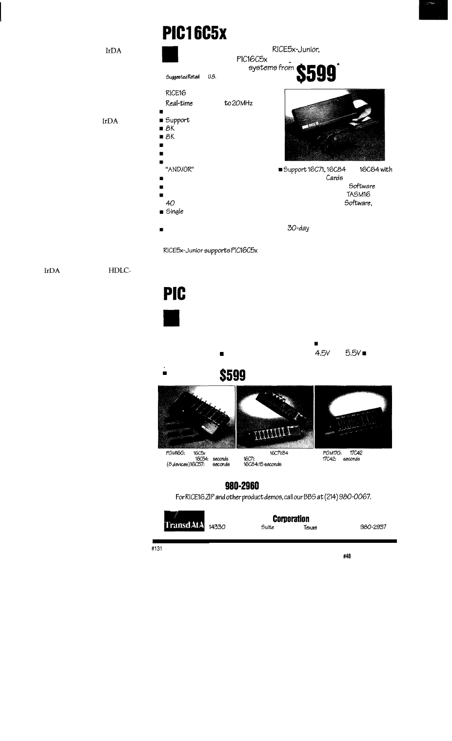
However, testing did show it’s
possible to glitch a transfer if you blast
your TV remote right at an
receiver. Fortunately, higher layer
software protocols can provide error
recovery to protect even the most
rabid channel surfers from shooting
themselves in the diode.
WHO’S ON FIRST
Speaking of software,
is also
defining the IRLAP (IR Link Access
Protocol) to establish and ensure the
integrity of communication links.
Though ostensibly a simple
“point-to-point” link, it’s clear that IR
isn’t as pointy as a good old-fashioned
wire. Consider the situation in Figure
4. Obviously a scheme is needed to
figure out who’s talking to whom, lest
everyone talk at once or a device end
up talking to one partner and listening
to another. Also, whether due to low
battery or the shaky aim of an aging
society, the protocol must handle error
detection and recovery.
Rather than reinventing the
wheel,
has adopted an
like (High-level Data Link Control)
protocol. HDLC has been around for
many years, notably serving as the
basis for mainframe (remember them?)
communications. Perhaps its most
popular incarnation these days is as
the core of Apple’s LocalTalk.
The key points of HDLC are that
it is a primary/secondary scheme in
which multiple secondary devices can
communicate with a single primary
station that’s in charge of who gets to
talk and when. Transfers occur in
packets that consist of address infor-
mation, data, and CRC. In fact, there
are three distinct packet types: U
(Unnumbered), S (Supervisory), and I
(Information).
Resolution of situations like
Figure 4 is handled by an initialization
and a “discovery” process that’s kind
of like a bunch of yuppies networking:
“Who are you! What can you do for
me? Glad you met me.” Everyone
starts at 9600 bps and then negotiates
for a higher data rate.
ANTE UP
Before you fire up your soldering
gun, be warned that to drive on the
Real-time Emulator
Introducing RICE%-5x and
real-time in-circuit
emulator5
for the
family microcontrollers: affordable,
feature-filled development
l
for
only
Features:
Emulation
PC-Hosted via Parallel Port
all oscillator type5
Program
Memory
by
24-bit real-time
Trace
Buffer
Source Level Debugging
Unlimited Breakpoints
External Trigger Break with either
with Breakpoints
Trigger Outputs on any Address Range
12 External Logic Probes
User-Selectable Internal Clock from
frequencies or External Clock
Step, Multiple Step, To Cursor,
Step over Call, Return to Caller, etc.
On-line Assembler for patching
instruction
and
Optional Probe
n
Easy-to-use Windowed
n
Comes Complete with
Macro
Assembler, Emulation
Power
Adapter, Parallel Adapter Cable and
User’s Guide
n
Money Back Guarantee
n
Made in the U.5.A.
family emulation up to 20 MHz. It offers the
same real-time features of RICE16 without the real-time trace capture.
Gang Programmers
Advanced Transdata Corp. also offers PRODUCTION QUALITY
gang programmers for the different PIC microcontrollers.
n
Stand-alone COPY mode from a master device
n
PC-hosted mode
for single unit programming
l
High throughput Checksum verification
on master device Code protection
n
Verify at
and
Each
program cycle includes blank check, program and verify eight devices
Price5 start at
for
family
Throughput:
4
10
PGM47: for
10 seconds
for
13
Call (214)
today for our new catalog.
Advanced Transdata
Tel (2141999-2999
Midway Road,
104. Dallas,
75244 Fax (214)
The Computer Applications Journal
Issue
July
1994
71
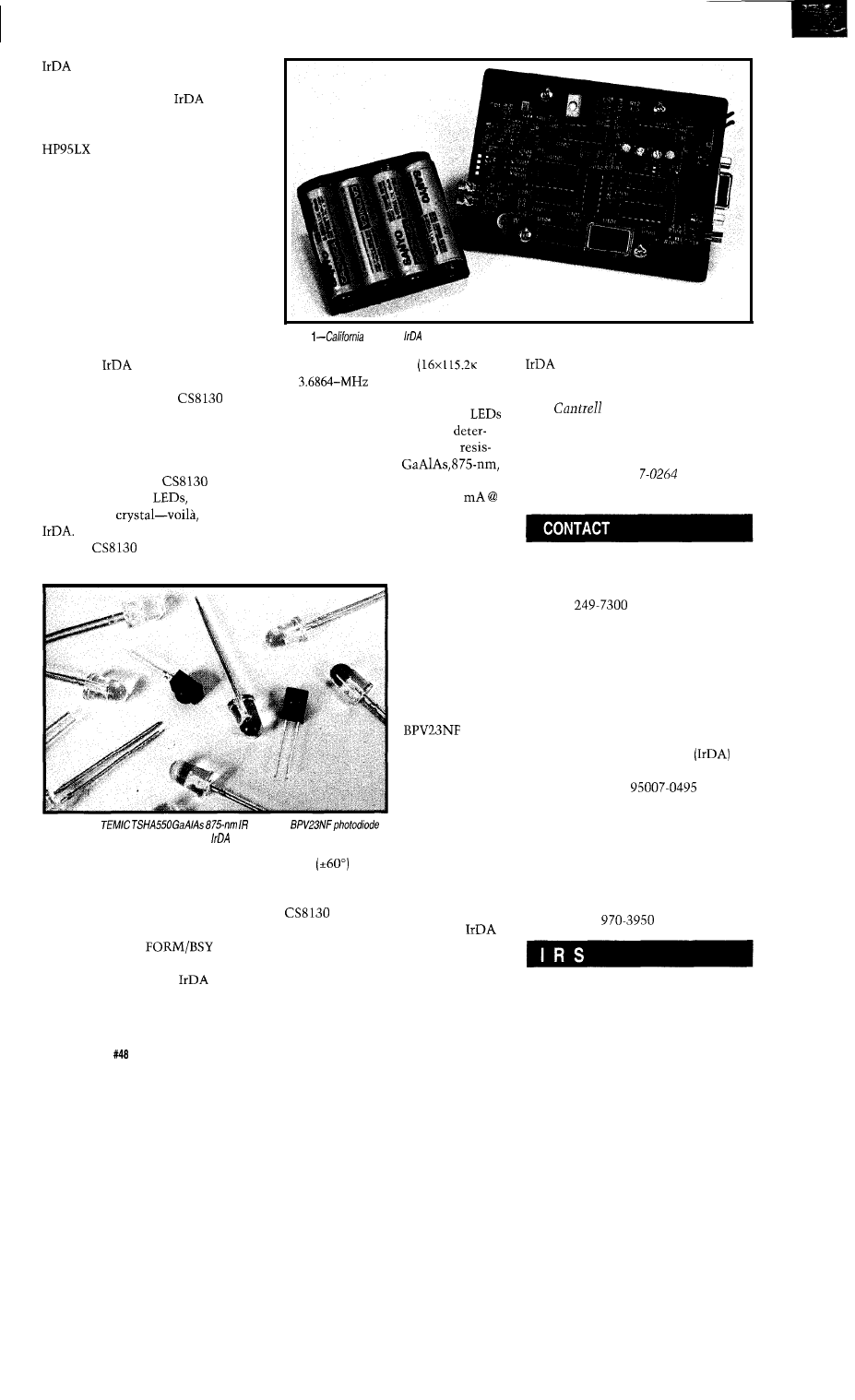
highway, you’ve got to get a
license.
Turns out that the
is largely
based on HP’s SIR (Serial Infrared)
scheme (used in products like the
and Omnibook), a technology
for which they have certain patents.
Lest you protest too much, my
impression is that HP is being “forced”
to make people pay in order to ensure
the “validity” of their patents. It’s only
fair to point out that HP didn’t start
the intellectual property arms race and
they won’t finish it. For good or for
bad, it appears the days of “free”
standards are over.
Fortunately, you can skip the
legalities and simply buy a chip from
one of the
roster’s many IC
suppliers, a good example being the
Crystal Semiconductor
shown
in Figure 5. Besides avoiding “party of
the first part” heartburn, an integrated
IC eliminates the need to fuss with all
those resistors and caps. As shown in
Figure 6 (the Crystal
EV
board), simply add
PIN photo-
diode, and a
instant
The
is set up (e.g., data
rate select) via TXD when the D/C *
Photo
Wireless
reference board.
to
either a 1.8432.MHz
bps)
a must for any well-connected
or
(depending on the
communicator.
q
CLKFR strapping] crystal.
Dual outputs can drive two
or a single LED at four levels
mined bv the current-limiting
tors. The TSHA550
IR LED from TEMIC is a good choice,
consuming on the order of 100
Tom
has been an engineer in
Silicon Valley for more than ten years
working on chip, board, and systems
design and marketing. He can be
reached at (510) 65
or by fax at
(510) 657-5441.
I.5 volts. At only $0.31 in thousands,
you can certainly afford to use two in
the equivalent of a car’s high-beam/
low-beam configuration. A smart
California Wireless, Inc.
618 Enos Ct.
Photo
2-The
LED and
are perfectly matched and ideal for use in
interfaces.
[Data/Command) input (typically
connected to a modem control signal)
is driven low. Otherwise (D/C* high],
RXD and TXD simply pass data
transparently between the computer
and IR sides. The
output
has dual use, indicating the IR format
(the chip supports both
and TV
formats] or busy handshaking. The
XTALIN and XTALOUT pins connect
transmitter can
“hit the brights”
for maximum
visibility.
On the
receiving end,
TEMIC offers a
well-matched
mate in the
photo-
diode (Photo 2)
which features a
spherical lens for
increased sensi-
tivity (quoted as
80% better than a
flat package) and
wide
viewing angle. Better yet,
it’s only $0.37 in thousands.
At the time of this writing, the
price wasn’t final, but you can
probably put together an entire
setup-IC, crystal, and diodes-for
less than $5.00 in moderate volumes.
With increased volume and competi-
tion, the cost will likely fall to a
couple of bucks, certainly making
Santa Clara, CA 9505 1
(408)
Fax: (408) 249-7301
Crystal Semiconductor Corp.
P.O. Box 17847
Austin, TX 78760
(512) 442-7555 x3253
Fax: (512) 445-7581
Infrared Data Association
P.O. Box 495
Brookdale, CA
(510) 943-6546
Fax: (510) 934-5241
TEMIC Customer Development
2201 Laurelwood Rd.
Santa Clara, CA 95054
(800) 554-5565 x25
Fax: (408)
419 Very Useful
420 Moderately Useful
421 Not Useful
7 2
Issue
July 1994
The Computer Applications Journal
Add Some
Code to the
John Dybowski
the BIOnet binary
network. This control/sense network
would most likely form the basis of a
fixed-base premises monitoring
system. It could function equally well
as the backbone of an industrial
equipment and apparatus monitoring
system. Although a variety of ways
exist to acquire binary data without
the use of any wiring-RF, IR, or even
power line-it is well known that
wired communications offers higher
levels of security when supervising
critical operations. The BIOnet
provides the advantages of a hardwired
system while dealing with some of the
difficulties associated with configuring
a wired system. This is accomplished
by providing bidirectional communica-
tions and power over a single,
cost, twisted-pair cable.
A standard configuration accom-
modates up to outlying satellite
units for a total of 60 inputs and 60
outputs. Applying a slight twist to the
technology, the BIOnet is supported by
the compact ec.25 Data Collection
Computer and can function as a data
acquisition subsystem. Combined
with the local digital I/O, analog I/O,
RS-485 and RS-232 serial I/O, and user
I/O via keypad and display, the ec.25
stands ready to function as a complete
portable (or stationary) data collection
and processing center. And being
optimized for low-power operation, the
ec.25 is capable of operating from line
power with battery backup or from
just battery for extended periods.
Since I was running out of space
last month, I had to start off with a
description of the second-level process-
ing that supports the BIOnet. This
discussion took hardly any space at all
since the second level operates as the
intermediary between the application
and the driver. It manipulates data and
hands off the real work to the BIOnet
driver code. This driver, shown in
Listing 1, is written entirely in
assembly language and is where the
line communications are actually
managed. Hopefully by the time I
conclude this column, it will be
apparent why I selected assembler as
the language of choice for coding such
bit-intensive operations.
Essentially, the driver program has
two user-callable entry points. As you
would expect, these perform the two
most essential operations associated
with network communications:
reading from and writing to a single
satellite module. BIOnet communica-
tions are carried out over a single
twisted-pair cable that is also used for
supplying power to the network
constituents. In this scenario, the
processor has the capability of inject-
ing 15 V and 0 V onto the line by
turning on one of two control bits.
These bits drive either a high-side or a
low-side switching transistor into
saturation, providing nearly a full-rail
swing. The intermediate 7.5-V level is
established via a resistor divider and is
the default condition when both
transistors are off. The line is moni-
tored using a simple inverting voltage
comparator that switches at about a
5-V threshold. If the line voltage
exceeds this threshold, it is interpreted
as a “one” bit; if it is less than 5 V, it
is a “zero” bit. It is just through the
use of these two output and one input
bits that communications with the
satellite modules is maintained.
There are different ways you can
go about writing peripheral drivers.
Sometimes circumstances permit you
to code the functions as you conceptu-
alize the algorithms in your mind.
Then there are those cases where the
implementation details bear little
resemblance to the underlying organi-
zation. There are many valid reasons
for departing from rational coding
techniques, but usually the driving
force is some pragmatic constraint.
74
Issue
July 1994
The Computer Applications Journal
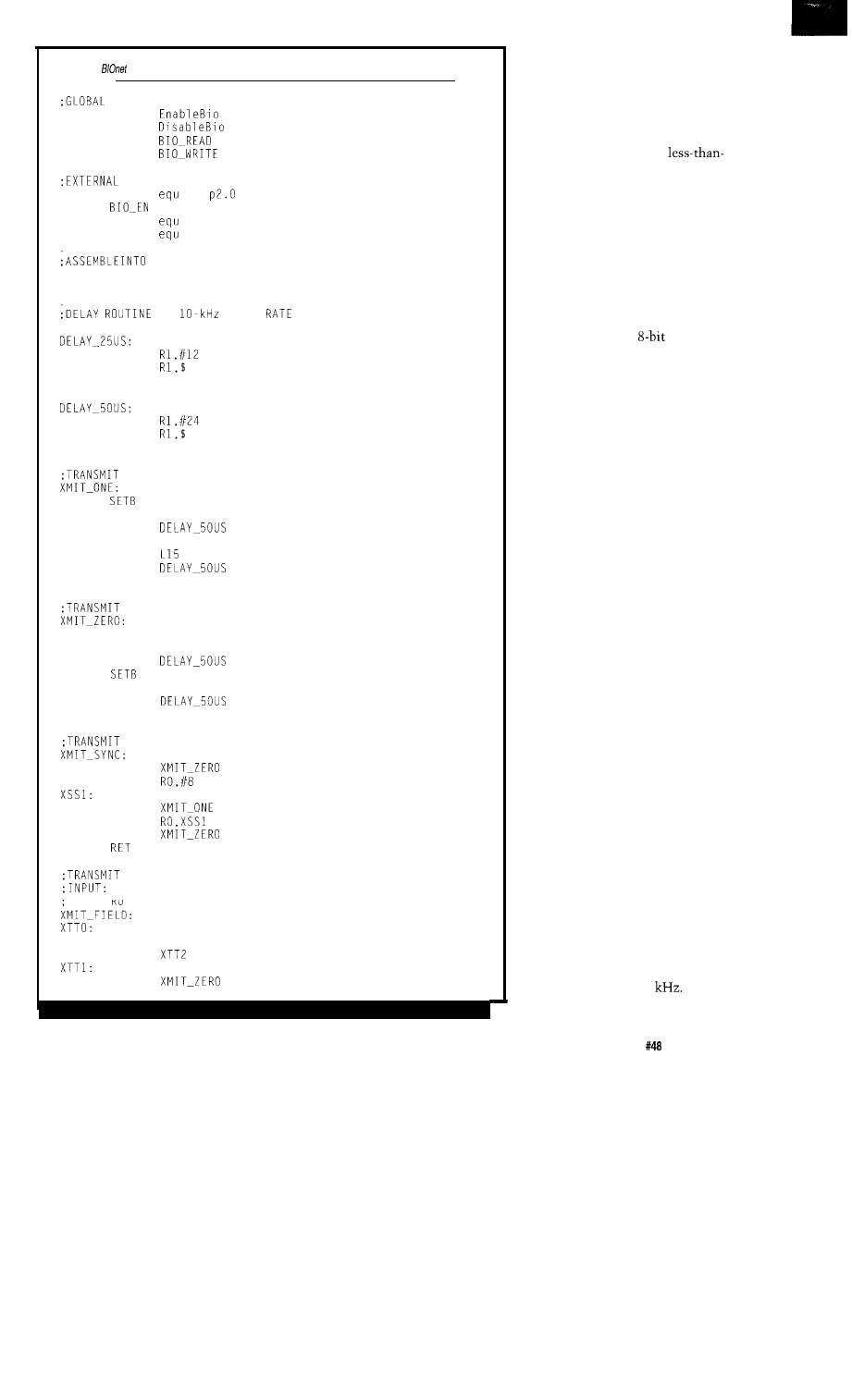
Listing l--The
driver code is where the real work happens in communicating with remote modules.
ENTRY POINTS
PUBLIC
PUBLIC
PUBLIC
PUBLIC
REFERENCES
SENSE
equ
p2.1
L15
p2.2
LO
p2.3
C O D E S E G M E N T
PROG
SEGMENT CODE
RSEG
PROG
FOR
SC
A
N
MOV
DJNZ
RET
MOV
DJNZ
RET
A ONE BIT OVER BIOnet
LO
CLR
L15
CALL
SETB LO
SETB
CALL
RET
A ZERO BIT OVER BIOnet
CLR
L15
CLR LO
CALL
LO
SETB
L15
CALL
RET
SYNC PATTERN OVER BIOnet
CALL
MOV
CALL
DJNZ
CALL
BIT FIELD OVER BIOnet
ACC CONTAINS BIT PATTERN
RO CONTAINS BIT COUNT
RRC A
JC
CALL
(continued)
Often, program or data memory
limitations tend to cramp your style,
or you may be approaching your
processor’s performance limits.
When faced with such formidable
constraints, engineers usually have no
choice but to fall back to
structured programming techniques.
Ideally, it’s best to partition your code
among several layers of virtual
processes. This tends to distribute the
complexity and permits you the luxury
of incrementally developing and
debugging the algorithms. As usual, it
pays to consider the overall issues
before getting too far along. This is
especially true when working with
some of the popular
processors
that are actually single-chip microcon-
trollers with external memory added.
The first thing to go in such an
arrangement is stack space since it is
often implemented in on-chip memory
and therefore is of fixed and limited
size. With heavy interrupt activity,
particularly with multiple levels of
interrupt priorities, you could easily
swamp the stack region if the mainline
code is layered too heavily. And when
it’s necessary to squeeze maximum
performance out of a minimal proces-
sor, the first thing you usually want to
do is limit your stack manipulations
and the associated overhead.
The end result of this brute-force
approach to performance enhancement
is straight-line code. Although such
coding needn’t be totally unstructured,
and if done properly can actually prove
to be quite intelligible, but it does fall
short of the ideal. The fact is, when
using economical processors, you have
to know when it’s appropriate to apply
what academic types would tell you
are inappropriate programming
techniques. Fortunately, this is not the
case with the BIOnet driver I’m going
to show you. Consequently, I will
proceed by starting with the smallest
pieces and working upwards.
Sometimes you just can’t seem to
be fast enough no matter what you do.
Then there are times when the
situation is entirely different and you
find you’ve got time to burn. Commu-
nications over the BIOnet can be
carried out at up to 20
Due to the
simple electrical line driving scheme I
The Computer Applications Journal
Issue
July 1994
75
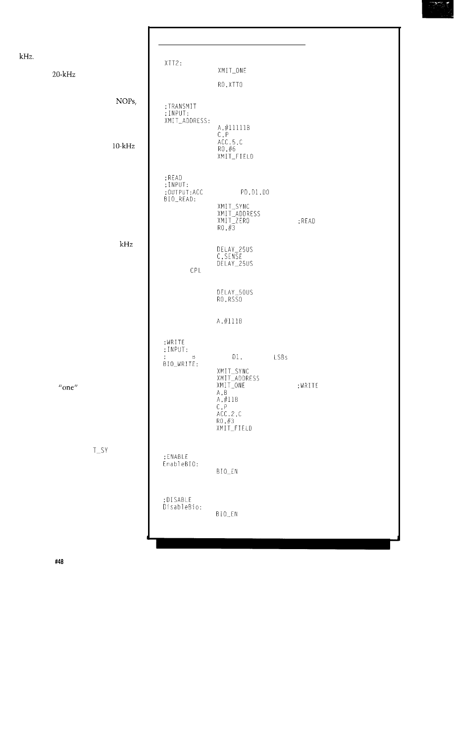
am running,
I
find I can squeeze a little
more distance out of the network by
running it at a more pedestrian
10
With such low throughputs, it
should be no problem sustaining the
maximum
data rate even using
a rather anemic processor. Rather than
waste time running delay loops or
executing endless sequences of
it’s much better to take advantage of
those extra clock cycles to render the
code in as straightforward and compre-
hensible manner as possible.
Having established that a
data rate is adequate for our purposes,
the first thing to do is to define a
couple of time delay routines in order
to fill out a half-bit time and a full-bit
time. Precision is not a requisite
function as far as BIOnet communica-
tions goes, so no attempt is made to
tune the delay loops to compensate for
the surrounding code. Actually, the
specified satellite communications
rate extends all the way from 20
down to DC. Note these figures
strictly define the communications
parameters and not the system
parameters. Holding the line low at 0
Hz would obviously deprive the
network of power in short order since
the data line is rectified and filtered to
provide power at the satellites.
The next couple of routines are
designed to transfer the smallest
communications component: a data
bit. Pulling the line from 7.5 V to 15 V
produces a “one” bit and taking the
line from 0 V to
15
V generates a
“zero” bit. The simplest bit stream
consisting of
and “zero” bits is
the sync pattern. Prior to the actual
transfer of information over the
BIOnet, synchronization with the
network satellites must be established.
This is done by sending a “zero” bit
followed by eight “one” bits followed
by a final “zero” bit. X M I
NC
performs this service using just a few
lines of code now that the supporting
functions have been established.
Comprehensible communications
require the transfer of varying bit
patterns of variable size. These fields
are the constituents of data packets
and are used to convey information
such as the satellite address, the read
or write operation, and the actual data
Listing l-continued
SJMP
XTT3
CALL
XTT3:
DJNZ
RET
ADDRESS OVER BIOnet
ACC CONTAINS BINARY ADDRESS
ANL
MOV
MOV
MOV
CALL
RET
BIOnet BITS
ACC CONTAINS BINARY ADDRESS
C
O N T A I N
S
IN
3
L S B S
RSSO
CALL
CALL
CALL
MOV
CLR
CALL
MOV
CALL
RRC
SETB
CALL
DJNZ
SWAP
RR
ANL
RET
L15
L15
BIOnet BITS
ACC CONTAINS BINARY ADDRESS
B CONTAINS
DO IN 2
CALL
CALL
CALL
MOV
ANL
MOV
MOV
MOV
CALL
RET
NETWORK POWER
CLR
RET
NETWORK POWER
SETB
RET
END
COMMAND
COMMAND
7 6
Issue
July 1994
The Computer Applications Journal
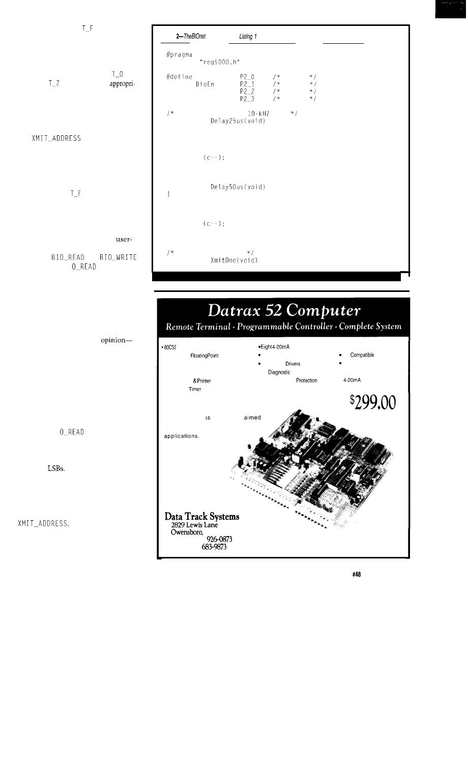
to be transferred. XM I
I E LD accepts
a bit pattern in the accumulator with
the number of bits to transmit in RO.
As the routine proceeds, the bits are
tested in sequence and control is
handed off to the low-level X M I
N E
and X M I
E RO routines as
ate.NowthatXMIT_FIELDisinplace,
which is a routine that simply trans-
fers raw data bits, the next level of
processing must deal with the actual
data content.
acceptsthe
satellite address in the accumulator
and assumes five significant bits of
data. The unused bits are masked off
and an even parity bit is generated and
appended as the MSB. Before control is
transferred to XM I
I E LD, RO is set
to 6 to indicate the number of bits that
are to be transmitted-five address bits
and a parity bit.
The functions I’ve described thus
far exist to serve the two main
callable routines. These are defined as
thepublic
and
entry points. B I
is responsible
for acquiring the status of the specified
satellite module. This status consists
of the state of the two input bits plus
the parity bit. Playing it safe, I invoke
the synchronization sequence prior to
every read or write operation since the
condition of the satellites somewhere
out on the wire is-in my
always questionable. Although it could
be argued that it is wasteful to perform
synchronization for every read or write
operation, experience proves it to be
the prudent thing to do. In any case, if
network performance becomes such
big issue, you could probably fall back
to doing the synchronization once per
network pass and still run fine.
The B I
routine takes the
S-bit satellite address via the accumu-
lator as its input and returns the
satellite status in the accumulator via
the three
Following the issuance
of the synchronization pattern, the
satellite address is dispatched. At this
point, the address has already been
properly positioned in the accumulator
and control is simply passed to
Next, a “zero” bit is transmitted
which tells the satellite that this is a
read operation. Immediately following
Listing
driver routines in
interface to this second-/eve/ support code written in C.
LARGE CODE
#include
Sense
1 = 0
#define
0 = on
#define Line15
1 = on
#define Line0
0 = on
Delay Routines for
rate
static void
unsigned char c:
c = 6;
while
return;
static void
unsigned char c;
c = 14;
while
return:
Transmit a one bit
static void
(continued)
CPU
l
High Speed
BASIC
l
32K Nonvolatile RAM
l
16K EPROM Programmer
l
RS-232 Corn
l
Watch Dog
Inputs
Four Discrete Inputs
Four Relay
l
12
Lamps
l
Extensive Surge
l
12124 Vdc Power
Options:
Bell
202 Modem
Clock/Calendar
l
32 Bit Counter
l
Output
The Datrax 52 a computer
primarily for data acquisition, process
control,
a n d g e n e r a l S C D A
A target and
development system using
HIGH SPEED FLOATING
POINT BASIC on a single
board. For a complete
description please
call or FAX.
KY 42301
Phone (502)
FAX (502)
The Computer Applications Journal
Issue
July 1994
77

the transmittal of this command bit,
preparations are made for entry into
the read loop. This loop executes three
times to read the satellite’s two input
bits and the parity bit. The loop
proceeds by first releasing the line to
7.5 V and, after a short delay, the input
bit is read and positioned. The satellite
is informed that the bit has been read
and that it may stop driving the line.
This is conveyed, in a rather blunt
manner, by yanking the line up to 15
V. After three iterations of this loop,
the code falls through and does the
final bit positioning, then clears any
superfluous bits, retaining only the
three least-significant bits in the
accumulator. These three bits and the
parity bit are returned to the
caller. Note that if an attempt is made
to access a satellite that is not present,
an idle line will be read which, by
default, returns three “one” bits. This
automatically registers as a parity
error, which is the desired result.
I
R I T E proceeds in a similar
fashion, but following the transmis-
sion of the address, a “one” bit is sent
to indicate that a write operation is to
follow. The output bits are pulled out
of the two
of B and an even parity
bit is appended before XM I
I E LD is
given control to transmit these three
bits. Enabling and disabling the 15-V
power consists of nothing more than
setting or clearing a port pin. For
completeness, these functions are
performed by a few callable routines.
IF YOU INSIST
Having coded the
driver in
assembler, it would be instructive to
look at how these same functions
could be rendered in a higher-level
language such as C. Now, some might
say that C is not really a high-level
language at all and would maintain
that it more resembles a stylized
assembler in its ability to get close to
the hardware. No matter how you
rationalize it, the fact remains that
some of the language’s power and
features tend to get in the way when
you’re trying to do things at the
machine level. Although I’ve managed
to go lower using C than I would have
thought practical, there comes a point
where you definitely begin to work
Listing
2-continued
Line0 = 1;
Line15 = 0;
Line0 =
Line15 = 1;
return:
Transmit a zero bit
static void
Line15 = 0;
Line0 = 0;
Line0 = 1;
Line15 1;
return:
Transmit sync pattern
static void
unsigned char c:
XmitZeroO;
for = c != 0;
XmitZeroO;
return;
Transmit a bit field
static void
char
while
if
&
else
XmitZeroO:
=
1;
return;
Transmit address
static void
Address)
ACC = Address:
ACC Oxlf;
= P;
Address = ACC;
Address);
return;
Read Satellite inputs
void
unsigned char c:
unsigned char Bits;
unsigned char Address:
Address = ACC;
78
Issue
July 1994
The Computer Applications Journal
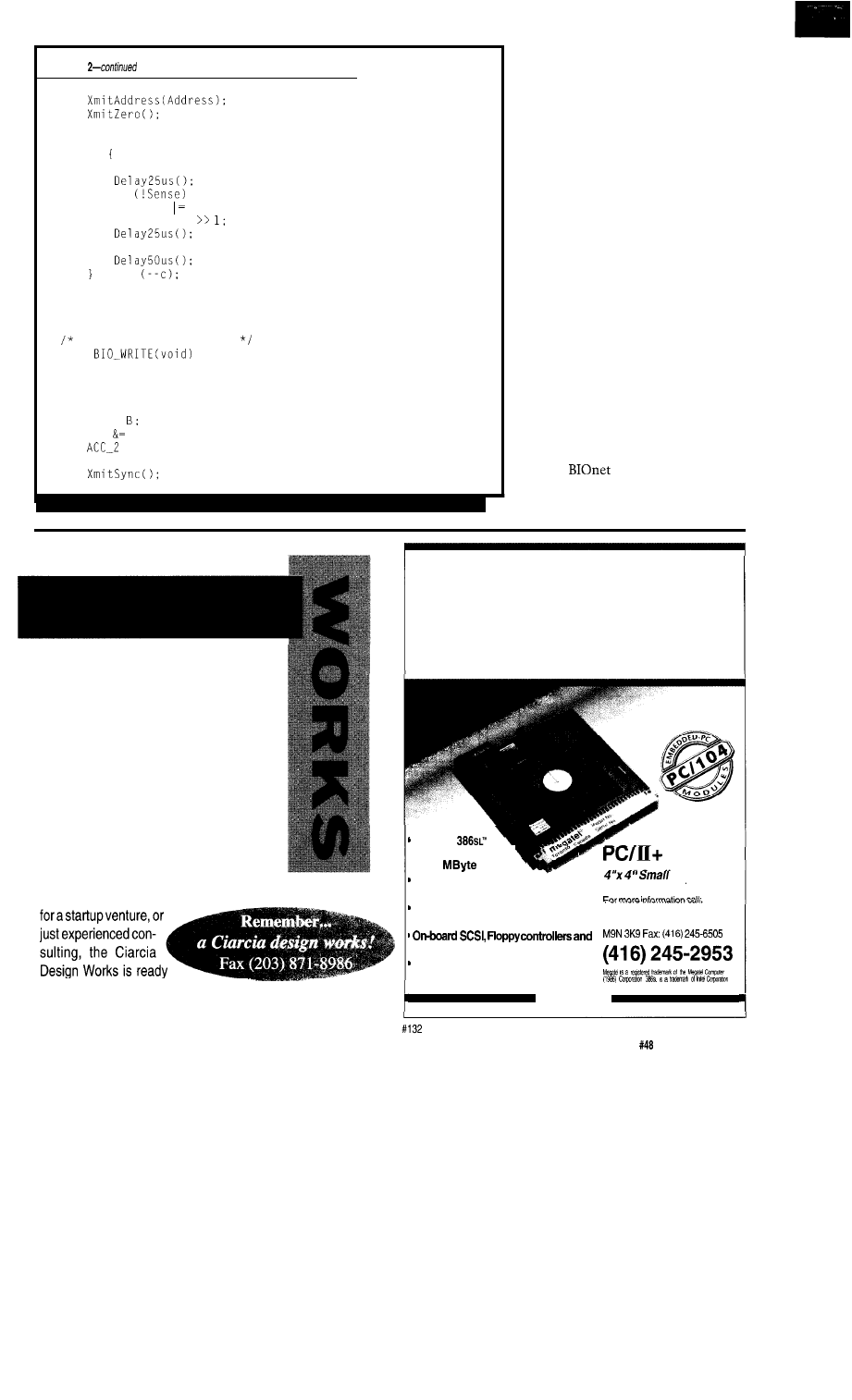
Listing
Bits = 0;
c = 3;
do
Line15 = 0;
if
Bits 8;
Bits = Bits
Line15 = 1:
while
ACC = Bits:
return:
Write Satellite outputs
void
char Address, Bits;
Address = ACC;
ACC =
ACC 3;
= P;
Bits = ACC;
(continued)
against your tools. Or are the tools
working against you!
When working with compilers, it’s
interesting to examine what the code
generator has been up to. In some
cases, I’ve been delighted to discover
that the compiler had, in fact, actually
done what I meant rather than what I
said. Unfortunately, there were also
those cases where my instructions
seemed clear enough to me, yet the
compiler decided to generate some
diabolically complex sequence that
somehow performed what I had
intended. It really does pay to analyze
the output of your compiler until you
get a good feel for the quality of code
you’re getting. Anyway, there does
come a point when you’re working on
the fringe, and using a code generator
becomes somewhat of a force fit. You
can tell when you’re pushing it when
you find yourself expending more
effort in coercing your tools than in
applying them to getting the job done.
The
driver interfaces to
the second-level support code, which
is written in C. Naturally, if you
D
oes your Big-Company marketing
department come up with more ideas
than the engineering department can
cope with? Are you a small company
that can’t afford a full-time engineer-
ing staff for once-in-a-while designs?
Steve Ciarcia and the Ciarcia Design
Works staff may have the solution. We
have a team of accomplished program-
mers and engineers ready to design prod-
ucts or solve tricky engineering problems.
Whether you need an on-line solution for
a unique problem, a product
to work with you. Just fax me your
problem and we’ll be in touch.
Embedded
P C
with on-board
Ethernet
and
Super VGA
25 MHz
CPU; including up’
to 10
DRAM
On-board Super VGA
LCD/Video controller
Rugged Format
On-board Ethernet, Featuring
AUI and 10 BASE-T interfaces
Megatel Computer Corporation
125
Wendell Ave., Weston, Ont.
2 MByte Flash Eprom Solid State Disk
3 Serial Ports,
Parallel/Printer port
megatel”
The Computer Applications Journal
Issue
July 1994
79
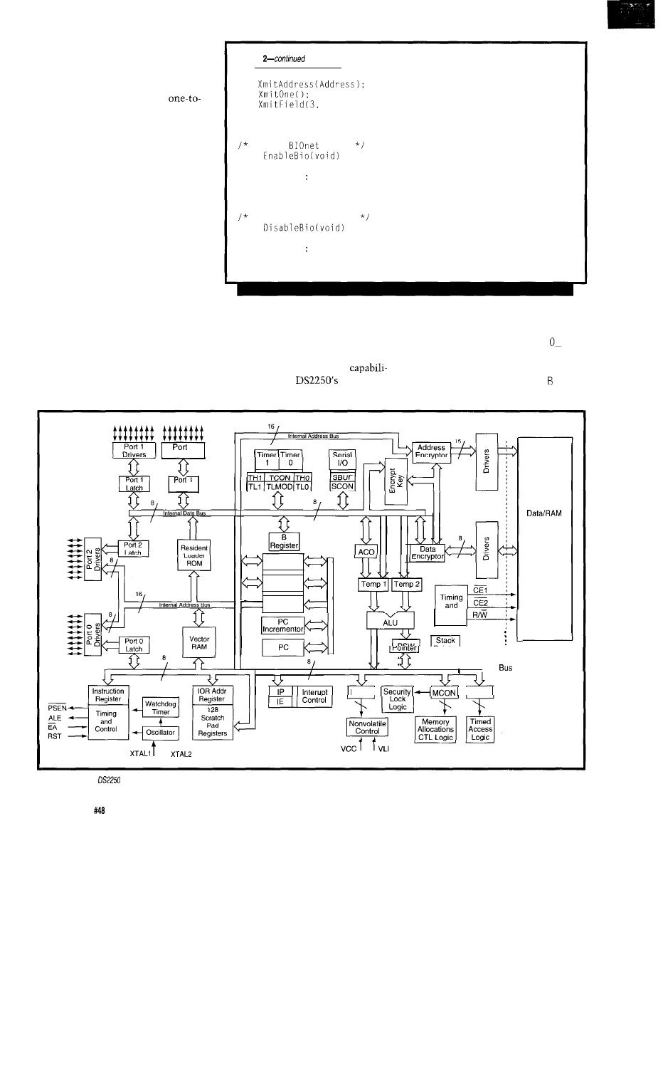
decided to code the driver in C, you
would be wise to use the inherent
parameter passing conventions of the
language. I didn’t follow this practice
here since I wanted to keep a
one correspondence between the
handcrafted assembler code and the
compiler-generated C code. This
shouldn’t obscure the basic structure
since it only involves a little front-end
and back-end processing to sort out the
passed arguments. Standard parameter
passing is used between the local
functions since this is primarily an
internal issue here.
Looking at Listing 2, you can see
that things start out fairly cleanly with
the basic time delay functions. Aside
from the need to consult the execut-
able code to verify that the proper time
delays will be counted, there’s not
much going on here. Similarly, the bit
transmission routines generate code
that corresponds very closely to the
original assembler. Likewise, the sync
and bit-field transmission functions
generate some fairly respectable code
as well. Looking at the address
Listing
Bits):
return:
Enable
power
void
BioEn = 0
return:
Disable BIOnet power
void
BioEn = 1
return:
transmission routine, you start to get
an inkling that things are taking a
downturn at this point.
All along, I’ve been using the
compiler’s special low-level
ties to get at the
hardware,
but now I find myself forced to dabble
at the processor’s register level to
facilitate parity generation. Things
continue to deteriorate with B I
READ, which is one of the main public
entry points. In case you’re interested,
the actual assembler output of IO_
READ is shown in Listing 3. This
3
Drivers
3
Latch
OPTR
Buffer
Program
Addr, Reg.
PC
Incrementor
PC
t
Control
J
Byte-Wide
Memory
PCON
I
I
TA
I
External
Program
Figure l-While
the
and the DS.5000 may look similar to the 8031, a peek under the covers reveals a host of new features.
80
Issue
July 1994
The Computer Applications Journal

illustrates several important points.
First of all, what the code looks like
and what it is are often two entirely
different things.
Obviously, source code economy
is not what we’re after, so don’t knock
yourself out making your source
statements so impenetrable that even
you can’t crack it. Secondly, if timing
were an issue here, obviously you’d be
in for trouble. Depending on the
particular compiler you’re using, it
may even be questionable whether you
can get the low-level control you need
for a specific task. To a great extent
what makes coding the
driver
in C practical are the compiler-specific
extensions that were included in this
implementation. To say that this is
not portable code would be a gross
understatement. The bottom line is
that coding drivers of this type in C
may not necessarily be in your best
interest. Even though the code does in
fact do the deed, it takes a little bit to
get from here to there. B I
R I T E,
although similar, produces somewhat
cleaner output.
MICRO IMPOSTORS
The DS2250 and
look
remarkably like a standard 803 1. This
is especially true from the program-
mer’s perspective. To this end, it
proves to be a good impostor since a
closer examination reveals that it is
something else entirely. Figure 1
shows the heart of the DS2250: the
This is the
circuit
that functions as the
(and
processing engine.
Although there are several blocks
that may look familiar to users of
it’s obvious that this is no 8031.
The designers did a nice job of preserv-
ing the basic 803 1 feature set and
overlaying this core with a bunch of
useful peripherals and enhancements.
Many of these new features are
accessed through the 803 l’s special
function registers (SFR). Here, it was
just a matter of the designers choosing
the most appropriate locations for the
new functions, since the existing
have numerous unused bits and bytes.
In my opinion, one of the most
useful enhancements is the preserva-
tion of all of the I/O ports while still
Listing
assembler
for
illustrates the difference between
code
looks like and
it actually is.
FUNCTION
(BEGIN)
MOV
LCALL
MOV
LCALL
_XmitAddress
LCALL
CLR
A
MOV
R5.A
MOV
CLR
LCALL
JB
MOV
ORL
MOV
MOV
CLR
C
RRC
A
MOV
LCALL
SETB
LCALL
DEC
R4
MOV
JNZ
MOV
MOV
RET
FUNCTION
(END)
supporting external program and data
memory. You can see from the figure
that the interface to external memory
carried over a dedicated data bus and
nonmultiplexed address bus. If you
exceed the bounds of the defined
partition ranges, address, data, and
control information will be emitted
over alternate functions of the I/O
ports, but normally this isn’t the case.
Other useful features include a
built-in reset and watchdog as well as
a power fail indicator interrupt. The
also contains the backup
control circuitry for the nonvolatile
program and data RAM and the real-
time clock. Related memory control
functions include the memory alloca-
tion and control logic, which defines
the total amount of memory and the
partition address between program and
data memory and the timed access
logic that controls access to the
processor’s critical control and
configuration regions.
Since the part is nonvolatile, it
should be evident that accidentally
reconfiguring the chip could render it
inoperative. This is why steps are
taken to protect certain sensitive
areas. The resident loader ROM
provides all the support required for
configuring the
and for
loading and verifying executable
program. The loader essentially gives
you a live processor right out of the
box. That is, before you even transfer a
program to it. Aside from communi-
cating with your system, the loader
lets you modify memory and I/O ports
and dump memory in a variety of
formats. Figure 2 reduces the
to a box and shows the
connections that are made to program/
data RAM and to the optional RTC.
This is what the DS2250 consists of
82
Issue
July 1994
The Computer

Byte-wide
Address Bus
DS1215
R e a l - T i m e
Clock
I
I
I
Figure
uses a resident loader ROM to provide the
support
needed
and I, in turn, depict this module in
my schematics with nothing more
than a box with 40 pins on it.
Now go sprinkle some satellites
around your home, office, or factory
floor and start collecting data.
Dybowski is an engineer in-
volved in the design and manufacture
of hardware and software for indus-
trial data collection and
tions equipment. He may be reached
at
Software for this article is avail-
able from the Circuit Cellar BBS
and on Software On Disk for this
issue. Please see the end of
in this issue for
downloading and ordering
information.
422
Very Useful
423 Moderately Useful
424 Not Useful
he Little
has 16 protected digital inputs, 14 high-current
outputs,
battery-backed RAM and real-time
programmable timers, watchdog, and more. The
Star
also available with enclosure and
expansion cards
‘or additional o. and optional
MHZ
clock. Our easy-to-use.
powerful Dynamic
development system
integrates
editor, compiler. debugger, and dozens of software libraries
in source code. The Little Star is ideal for
OEM
control
manufacturing automation, test and data acquisition.
from
Request
We offer a full line of low cost
embedded
controllers and software tools which are ideal for
developing products, test fixtures and prototypes.
Features Include:
Low power CMOS design
Up to 60K of code space and up to 60K of data space
5 to 15 volt operation
Small
form factor (3.5”
l
6.5”) with prototyping area
System
diskette includes application notes
Start at $100
Available Options:
Multifunction Board adds ND, 24
lines and more!
BASIC-52 or Monitor/Debugger in EPROM,
C Compiler $100 or BASIC Compiler for $300
Iota Systems, Inc.
POB 8987
l
Incline Village, NV 89452
PH:
l
FAX: 702 831-4629
The Computer Applications Journal
Issue
July 1994
83

The Circuit Cellar BBS
bps
24 hours/7 days a week
(203)
incoming lines
Internet
This month we’re going traverse the limits from high-voltage
concerns down low-voltage and -current issues. first thread,
we look at whether paranoia surrounding potential
damage
CMOS devices is
real or is now just imagined. The other
thread this month deals with minimum current and voltage
must
through a set of relay contacts keep them clean and reliable.
ESD-Myth or reality?
From: MARK SERBU To: ALL USERS
I’m trying to get opinions from anyone who’d like to
give one on the subject of ESD. The company I work for is
so paranoid about ESD that virtually anything that seems
remotely qualified as static sensitive is put in bags, foam,
and so forth. To not follow ESD procedure is to get your
butt chewed. It’s gotten so bad that even a component we
stock which is designed to shunt lightning to ground is
under the same severe ESD protection as a CD4000 series
look-at-me-wrong-and-I’m-history chip!
My own experience with ESD is that it is no longer a
factor. I’m using the same CMOS chips (modern HCT
types) that I’ve had and mishandled for years and they still
work fine. I’ve never had a failure of any kind!
IS
this a big
scheme by the ESD paraphernalia manufacturers or is there
some truth to it all? I’d love to hear some war stories on
this one!
From: ED
To: MARK SERBU
I’d say it’s largely reality with a goodly dose of hype
thrown in..
The trouble with the “I’ve done it hunnerds-a-times
and ain’t
happened yet” approach to ESD [which
I’ve used myself for quite a while) is that you
tell
when you’ve zapped a chip. The energy required to draw a
spark is one or two orders of magnitude higher than that
required to damage an
worse, the damage may be
noncatastrophic so you say, “Well, that chip sure is tough”
when you’ve really shortened its life or increased the
leakage or whatever.
My take is that you should exercise reasonable care,
use a grounded mat, ground yourself to the mat, and don’t
84
Issue
July 1994
The Computer Applications Journal
do stupid things..
you needn’t bond yourself to the
nearest water pipe and fill the air with ions. Of course, if
you’ve got a manufacturing process that must be certified
safe, all bets are off..
From: FRANK
To: MARK SERBU
I have a good ESD story. About three years ago, we
were designing a 128 x
infrared camera using a
Rockwell NICMOS detector. The 128 x 128 device con-
sisted of a CMOS multiplexer with a layer of
(Mercury-Cadmium-Telluride) diodes bonded to the top
surface of the mux. This particular device had *no* EDS
protection for the CMOS mux, so, not surprisingly, my boss
was very paranoid about assembly procedures. We bought a
flow bench with a high-voltage grid and ground plane
(chicken wire) in front of the air stream that would, in
principle, remove all charge from the air. On top of that, we
had a grounded work surface on the flow bench and
grounded wrist straps.
For some reason, we started killing arrays! We went
through the usual list of suspects: detector installed
incorrectly, cryogenic failure, you name it, but we were
quickly running out of arrays and engineering samples (at
each, we didn’t have drawers full of them].
Luckily, Rockwell is a fine bunch of people and they
wanted to get rid of their old engineering stock for this
device, since they had moved on to 256 x 256 devices.
We couldn’t figure out why the arrays were dying, so I
carefully observed our assembly procedure-the dewar
(about 2 feet high) was placed in the flow bench, the air was
turned on, wrist straps donned, and the array removed from
its box and carefully placed on a grounded surface. Then it
was carefully picked up and slowly moved to the socket
inside the dewar. It was then that I noticed the high-voltage
electrodes behind the flow bench ground grid were about 2”
wider than the grid.
As a long shot, I mapped out the voltage potentials
(with an ESD meter that I’d borrowed) of different objects in
the flow bench. The grounded work surface and array box
were at ground, but as I measured the voltage near the top
of the dewar, it was well over 40 V! The resulting map
showed that the undersized ground grid was letting the HV
electrodes charge up everything on the bench! Indeed, after

turning off the flow bench, we had no more losses. We also
moved on to the larger arrays, which are much easier to
work with and do have static protection. We don’t use the
flow part of the flow bench any more, though.. .
We called the flow bench maker, and their answer was,
“Urn, we decided to make the grounding grid a bit
smaller.. .I guess it doesn’t work, huh?”
From: DAVE
To: ED NISLEY
use a technique that I’ve developed over the years, and
confirmed with several chip manufacturers:
1. Wood bench. Not plastic, not metal. It’s somewhat
conductive, and not prone to generate anything significant.
2. When handling chips, if I need to hand a chip to
someone, I drop it into their hand. The chip carries only a
very small charge at my potential. Alternatively, for really
expensive or sensitive devices, I touch their hand first since
that will equalize the charge.
3. When inserting chips into boards, or handling boards
in general,
I
touch an exposed ground-point first.
4. I use a grounded ring around the perimeter on all my
boards and attach metal connector parts to that ground ring.
It also helps layout tremendously.
The whole idea is to bring everyone to the same
potential rather than trying to get to “ground.” If we are all
at the same potential, then no damage. It’s the “bird on a
wire” approach. I’ve seen many designs that were tied to
earth ground in an attempt to “fix” an ESD problem that
were actually made far worse than before. It’s like a boat at
anchor with a short chain. The tide comes in, and.. .Glug! I
prefer to float the circuit wherever possible and assure that
any energy coming in has to see local ground first. I’ve
applied that in several million pieces of shipped product and
it works well in real-world conditions.
If I have to tie to earth ground, then I tighten up a bit
on protection at the I/O points and try to move sensitive
circuitry (memory protection) to the center of the board.
From: ED NISLEY To: DAVE
Sounds good to me..
you usually have to
explain to somebody why you’re touching the hand before
passing the part to ‘em. Such is society..
And, besides, wood benches
nicer, too. The
trick is to justify real wood rather than plastic laminate!
From: DAVE
To: ED NISLEY
Well, just show them the bill for the complete ESD
workstation, then ask if you could just get two file cabinets
and a 6’ x 3’ door. Works every time.
Sometimes they get nervous though with
of
equipment solely supported by a $20 door. Never had one
fail, though!
From: ED NISLEY To: DAVE
Hey, and it’s probably at the precisely correct ergo-
nomic height, too. Nice work!
From: PELLERVO KASKINEN To: MARK SERBU
Myth or reality? Actually it can be both, depending
on the circumstances. If you operate at relative humidity
above
it probably is very close to the “myth.” But get
down to 15% or below and you could not even blink your
eyelids without creating too much static for the chip to
survive.
From: MARK SERBU To: PELLERVO KASKINEN
Pellervo, I guess that here in Tampa we’re close to 90%
humidity a lot of the year, so that may be why I have such
good luck not blowing out parts. I do miss the ability to
scrub my shoes on the carpet and give my cat a shock,
literally.
Contact Rating
From: GEORGE NOVACEK To: ALL USERS
Not long ago there was a discussion on this BBS
regarding relay contact rating. The maximum voltage and
current in particular. I have a question regarding the
opposite end, that is, the minimum allowable current.
There are requirements to maintain a certain minimum
current through contacts-on a relay or mechanical
switch-which depend essentially on what the contact
material is.
Since I do aerospace work, I have always played it safe
and specified gold-plated contacts. Now one customer is
telling me he is not going to use gold-plated contacts and I
have to make sure the pull-up resistors put enough current
through the contacts for reliable connection. I do not want
to go overboard as power dissipation and weight are an
important factor. I need data to substantiate whatever
current I am going to select. Referring to the old rule of
thumb will not fly-literally. Any idea where I can find
such information?
The Computer Applications Journal
Issue
July 1994
85

From: CHRIS HAYNES To: GEORGE NOVACEK
I
ran into this problem using Potter Brumfield T92
series relays. The applications engineer there was very
helpful and informed me that my relay had a minimum
load of 150
Running much below that level caused the
contacts to wear quickly. I recommend talking to the
manufacturer of the relay.
As a side point I have come across some stuff called
“Stabilant R.” This stuff is supposed to allow tin-plated
contacts to act much like gold contacts. I have a friend who
uses it on some terminals in one of his greenhouse projects
and he swears by it. However, this stuff isn’t cheap; it costs
about $50 per ounce.
From: GEORGE NOVACEK To: CHRIS HAYNES
Thanks for your interest. I know Stabilant, used it, and
have nothing good to say about it. In this situation, how-
ever, I have no access to the contacts. They are provided by
someone else. I only have the contact closure to work with.
From: PELLERVO KASKINEN To: GEORGE NOVACEK
The low current limit varies widely, as you might
guess. If your contacts are built to handle 100 amperes, they
are not suitable for the low-level currents. But even the
low-level-specific contacts are not infallible. If you have
both a low voltage and a low current, the task is more
difficult than if one of those two is reasonable.
The basic approaches for low-level contacts in relays
rely on bifurcation, which provides redundancy and in-
creased contact force by shaping the two contacts like
wedges. Then you have them crossed, to produce a point
contact with the associated high local pressure. Penetrates
any oxides and so on. Naturally, you want the contact
material itself to be as inert as a metal can, without relying
on an oxide film for the inertness. Gold is the material of
choice in any atmospheric situation.
There also are the sealed (reed capsule and other
implementations) relays that have an inert gas filling or a
good vacuum. Both these reduce chances of contamination
and promote dry circuit (low-current) operability.
Another approach has always been the mercury-wetted
contact. While used in some of the best relays for low-level
signal switching even today, they are not very popular for
the environmental reasons. A high price and position
sensitivity in most designs are also impediments.
The latest additions to the bag of tricks are photo
switches, such as the PVR series from International Recti-
fier. Other sources for these photon-actuated FET switches
are AT&T and Aromat, plus probably several more. These
86
Issue
July 1994
The Computer Applications Journal
switches have the benefit of very low thermal EMF, which
is beneficial for thermocouple selectors in data logging
applications.
Whenever a relay is specified for a “dry circuit”
application, you can generally trust that it will work to well
below 0.1
but getting the exact figures requires either
help from the relay manufacturer or your own trials. It is
also a question of how many million operations and what
your criteria are for the failure. If the circuit allows a 0.2-V
drop in the closed relay contact while carrying 0.1
we
are talking about
contact resistance! You nor-
mally expect 50
as a reasonable contact resis-
tance, so we are talking about an entirely different expecta-
tion here.
As to your change from gold to silver contacts, I would
be worried, no matter what power dissipation you design in
the pull-up resistors. I cannot see how YOUR customer
would accept the change, so you should not either. Aero-
space? I hope it is not going to be on any airliner that I’m
going to trust for my traveling needs..
From: GEORGE NOVACEK To: PELLERVO KASKINEN
Thanks for your reply. I have been in the business
longer than I care to remember and am well aware of
methods to do it right. Unfortunately, this is a situation
where I am designing a flight control box, with the aircraft
interfaces outside my design authority. The ones in ques-
tion are discrete signals, such as weight on wheels, which
were defined to me as either open or closed contacts. Only
now, after the fact, the airframe manufacturer came to us
and said, “By the way, the contacts will not be gold plated
but rather silver plated, rated for 25 A. We are concerned
that your pull-up current is insufficient and expect you to
either prove to us otherwise or increase the current accord-
ingly.
Fortunately, it is not a safety issue. As you may know,
in my business the functionality is a given. Achieving it
represents hardly more than 20% of the design effort. We
spend more time designing for failure because everything
will eventually fail and we must ensure it fails in a safe,
predictable manner. Because of the system redundancies
and BIT (built-in test], I will know when a contact has
failed. Also, because of the noise margin built into the input
circuits (I need to operate in E-fields of 400 V/m and take
Level 4 lightning hit), I can tolerate up to 3k contact
resistance. The issue is primarily maintainability. Once
there is high incidence of contact failures (detected and
indicated by my equipment), I will get the blame. Always
blame the messenger!
I am trying to alleviate this very real potential problem
by convincing my customer it would be cheaper to spend a
few hundred bucks extra building a $15 million airplane
than blowing a lot more later in a retrofit program. It is
difficult to convince someone to spend money by using
arguments such as experience, rule of thumb, and so forth.
For an engineer (as well as a bean counter), there is nothing
more convincing than a good set of numbers. That is what I
was looking for when posting my message.
In the meantime, I talked to several relay manufactur-
ers in hopes of obtaining solid data. Basically, they all tell
me that anything less than 10% of the rated current should
be considered low load and viewed with suspicion. Based on
that, I should have at least 2.5-A pull-up current. That, of
course is ludicrous, since the entire controller is allowed to
consume no more than 35 W. From this perspective it also
means it makes no difference whether I stay with
pull-ups or increase them to 5
(absolute maximum for
the allowed power). Either way, I am still a long way from
2.5 A. The 3k contact resistance tolerance seems to be a big
plus. Manufacturers of high-quality relays, such as Leach,
can implement a screening program which will test the
A rated devices at their intended load. But even then,
anything other than gold plating raises eyebrows.
My design has to pass the salt fog, sand, and dust test. If
you have ever seen the inside of a dual-cavity box with only
a single 0.020” hole for pressure relief after such tests, you
would be wondering why would anyone even consider using
nonhermetically sealed, nongold-plated relays in such an
environment or, conversely, if such environment is not real,
why would he want any piece of equipment meet such
environmental conditions. It ain’t cheap to achieve.
It looks like there is no solid data I can take and beat
over my customer’s buyer’s head. Probably my only course
of action is to write a memo, strongly recommend they use
gold-plated, hermetically sealed, low-load screened con-
tacts, send it out, and when eventually the
* hits the
fan, wave it around and say I told you so.
From: PELLERVO KASKINEN To: GEORGE NOVACEK
Pretty much what I figured your situation might be.
Sounds to me like you are in a no-win position.
five-amp contacts! Those relays have almost dime-size
contacts and I am every bit as scared as I was last time
about the choice. Why in all the world would the
need
such monsters? Is it just another case of standardizing on a
single type of something for minimizing the inventory
requirements?
From: GEORGE NOVACEK To: PELLERVO KASKINEN
That’s what it primarily is. Minimizing inventory and
getting a volume discount from the vendor. Also an attempt
to minimize certification costs by marrying old technology
with new. In the aircraft industry, there is what is referred
to as grandfathering. Essentially, you use as many old parts
and systems as you can and claim they are being
fathered. If accepted, it reduces the time, effort, and cost to
certify the particular part or system tremendously. Boeing
737 has been grandfathered so many times I lose
although, I need to add, there is nothing wrong with it, and
Boeing, in particular, never compromises on quality and
safety. What usually puts a stop to endless grandfathering is
a new requirement. Recently, for example, new regulations
increased HIRF/EMI requirements and included lightning
strike susceptibility to such proportion, very little elec-
tronic equipment can avoid redesign.
The aerospace industry is extremely conservative-it
must ensure personal safety. Most of the “cutting edge”
technology was done on military projects. There, funding
used to be plentiful and a loss of an aircraft was to some
degree acceptable. This is not the case in the commercial
part of the industry. Basically, equipment that has been
flying for a couple of years is specified even for the future
projects and something new is procured only if the old
and tried stuff does not exist. Fortunately, in my area
everything must be designed from scratch. But I caused
quite a commotion in a boardroom of one company when I
proposed to use fuzzy logic. I am using it anyway, an
algorithm is an algorithm. I just don’t use the silly name
any more.
Back to the relays. It is not a safety issue and, my tests
show, it will work for quite some time. It is just silly and I
don’t like it. I in fact wish I could show it compromised
safety. Because then it would be changed even before I
finished writing this reply.
From: PELLERVO KASKINEN To: GEORGE NOVACEK
I have been thinking this issue for the past week, trying
to come up with a constructive suggestion. I came up with
something, although I cannot claim right away that it is
terribly constructive.
A little background: I once subscribed to a Swedish
radio and electronics magazine. They had in every issue
some outlandish trick question that the readers were
invited to answer, sincerely or not so sincerely, depending
on each person. Then the best of the answers were printed
in a later issue. Now, one of the questions was about a
black box that from a DC supply consumed 1 A of current
while the terminal voltage was 1 V. Yet, a watt meter also
attached showed 0 W. All instruments were perfectly
functional and accurate. What was there in the black box?
The answer was a chopper contact that produced a 50%
duty cycle, a short and an open. Oh, I failed to mention the
The Computer Applications Journal
Issue
July 1994
87
internal resistance of the DC power supply was specified as
well.
What all this means is you could have plenty of current
and very low power dissipation if you choose to chop the
sense current. You would provide in essence an inductive
path whenever the external contact is made and no path
when it is open, but you would have the chopper and other
energy reuse facilities built right into your portion of the
circuit.
Of course, you could just try lowering the duty cycle of
ordinary sampling pulses, never resort to the inductive
circuits. Just repeat a
sampling pulse of
1
ampere or
so from 5 V a few times per second. Charge up a capacitor
to provide the jolts..
Well, I do not know what consequences the pulsing
would have to your other parts and the noise issues and so
on, but at least I came up with something to further the
thinking processes of the creative minds among the sub-
scribers to this board, didn’t I?
From: GEORGE NOVACEK To: PELLERVO
An interesting idea. I did tell the customer to do his
part of the job right and give me proper contacts. However,
it is something to keep in mind for the future.
There are some minor problems, such as the fact that
we usually work with 16 to 32
To keep the cost
down, I could always multiplex them. A typical system has
a dozen analog inputs which are multiplexed anyway, so
what’s a few more lines? The test current would be injected
through the multiplexer.
Another problem, of course, is the EM1 spectrum. A
square wave is a big no-no. Therefore, most data communi-
cation systems use trapezoid, which is fairly accurately
defined. This goes hand in hand with the redundancy
requirements. In a typical fail-safe system, I work with dual
redundancy (triple for fail operative). So, I have two inputs
with identical data and two microprocessors to process
them. Input 1 and 2 must tally on
as well as
and
then
and
compare their results and they must tally
as well. In addition, to make sure I am not reacting to
transients, I must have a failure condition to persist for
three to four counts. In total, however, I must be able to
declare fault and take action in 80 to 100 milliseconds.
Simple mathematics will show you that the time slice
for data acquisition gets shorter and shorter. Some time can
be saved by synchronizing both microprocessors, but it is
tricky. You must make sure there is no single point failure
in hardware, nor common mode failure in software (which
means the two programs must be different and sometimes
even the micros are different; some people go as far as using
one from Motorola, the other from Intel). All that cuts into
88
Issue
July 1994
The Computer Applications Journal
the time and once we
out voltage or current
pulses, the shorter they ar
higher their spectrum. Both
radiated and conducted er sions can become a nightmare
real fast.
From: BEN MEHLMAN To:
NOVACEK
Sounds like
its best. Certainly you
shouldn’t have to be
with a 25-A relay contact for a
control input, and that is
root of the problem. There are
power relays out there wit
sets of control con-
tacts....
Anyway, assuming
an’t get the problem fixed at
the source, here’s a suggest
Use an arrangement with a
capacitor to provide a high
briefly during contact
closure. Once the contact
your lower “seal-
ing” current might be adeq
Mind you I am not a relay
expert, but it seems like it
increase reliability..
From: GEORGE NOVACEK
BEN MEHLMAN
An interesting idea, al lough something like that
already exists because of
caps on the input.
I’ll look into it. Thanks.
We invite you call the
rit Cellar BBS and exchange
messages and files with ot Circuit Cellar readers. It is
available 24 hours a day a
may be reached at (203)
1988. Set your modem for data bits, 1 stop bit, no parity,
and 300, 1200, 2400, 9600,
bps. For information on
obtaining article software
the Internet, send
to
Software for the articles in his and past issues of The
Computer Applications
may be downloaded from
the Circuit Cellar BBS free charge. For those unable to
download files, the
is also available on one 360K
IBM PC-format disk for
$12.
To order Software on I
send check or money order
to: The Computer
Journal, Software On Disk,
P.O. Box 772, Vernon, CT
or use your VISA or
Mastercard and call (203) 8
Be sure to specify the
issue number of each disk
order. Please add $3 for
shipping outside the U.S.
425 Very Useful
426 erately Useful
427 Not Useful

One Man’s Junk...
m sure you’ve heard the expression that one man’s junk is another man’s treasure. wouldn’t have
believed this if hadn’t experienced it so often. Apparently it has gotten around town that have some of the
best junk. Whenever a carpenter or handyman does work around our property they go home with a trunkful. Last
summer took down a
garage (replaced it with a larger garage and workshop) and, believe it or not, none of the contents ever
made it to the curbside pickup. Someone even dismantled the garage and took that away!
We engineers shouldn’t laugh too loudly about collecting things. Somewhere you probably still have your first computer (or first
couple), a bunch of hardwired interface kludges, and piles of old technical books. Why do I still keep those college statics and
dynamics texts?
We collect some objects because they have special meaning or remind us of specific turning points in life. I have eight original
Tinney paintings hanging on the walls of our living room. I purchased them from Robert because I wanted a distinctive and unique
reminder of past associations and achievements, When I look at my painting of the robot hand breaking out of the egg (Technological
Breakthrough), it stimulates thoughts of recent evolution.
I’m embarrassed to admit that apparently many of my project presentations have had similar effects. Often I am told that a
particular project caused someone to change a career path, win a science fair scholarship, save their senior project, start their own
business, or just plain incite new awareness. One guy wrote and told me (back in ‘78) that my using an EPROM to replace sequential
logic saved his job.
Well, embarrassed or not, I’ve decided to clean house. The Circuit Cellar is getting a little tight from old project boxes and folders
going back 15 years. If you are among those who had thought about asking for a unique reminder of that critical juncture in your past,
now is the time. If you want some Ciarcia original junk-for mere shipping costs-perhaps we can resolve mutual goals.
First of all, there are over 100 projects going back to ‘77. If you have a particular project in mind, let me know and list some
choices.
tell me if, in lieu of those, anything will do. The early years are primarily folders containing the raw manuscript and
perhaps the author’s proof. Most of these early manuscripts are handwritten! The more recent projects might still have chip samples or
hand-wired boards.
I offer this stuff as unique junk-first come first served. I don’t guarantee the complete contents of anything, that anything
included works, or that it’s anything more than a unique piece of Ciarcia junk. send it to you and you reimburse me for the shipping
after you receive it. Frame it and forget it.
I’ve kept this stuff this long because it meant something to me. I relish the thought of it finding a home with someone it has
positively influenced. To participate, write me here Ciarcia’s Project Boxes.
96
Issue
July 1994
The Computer Applications Journal
Wyszukiwarka
Podobne podstrony:
circuit cellar2001 07
circuit cellar2000 07
circuit cellar1995 07
circuit cellar2002 07
circuit cellar1993 07
circuit cellar1994 07
circuit cellar1996 07
circuit cellar1997 07
circuit cellar2004 07
circuit cellar2004 07
circuit cellar1996 07
circuit cellar1995 07
circuit cellar1997 07
circuit cellar1993 07
więcej podobnych podstron