
Habitech95
magine walking onto a show floor and finding
over 80 exhibitors showing their home automation
wares. Turn around, walk down the hall, and you find
dozens of home automation classes and seminars dealing
with topics such as equipment selection, installation, customer service, and
marketing. Such was the recent scene in Atlanta, the site of Habitech95.
Habitech is the home automation industry’s only trade show. It hosts
virtually every key player in the HA arena and is Mecca to HA dealers,
installers, enthusiasts, and those just thinking of getting their feet wet. It’s
also the place to size up the state of the
and see what’s new.
The majority of exhibitors displayed independent subsystems that
control a specific aspect of the home. Lighting systems, drapery controllers,
audio/video distribution, HVAC controllers, security systems, and even
central vacuum setups were represented. However, as Greyson Evans
points out in his article in the HABC insert, for the
to truly grow, we
need a unified method of communication
between these subsystems to
enable them to interoperate.
There are a number of contenders wanting to facilitate that communi-
cation, and the question in everyone’s mind continues to be, “Will it be X-10,
CEBus, or
X-10 continues to hold the lead in terms of price. There were even new
X-10 products that address some of the shortcomings people have
complained about for years. Powerline Control Systems (PCS) has a
number of X-10 offerings that gradually brighten from off (rather than going
to full on first, then dim), preset dim, and microdimming. While pricey, I think
they’ll be popular among X-10 diehards. They are also shipping now.
As for CEBus versus
the juty is still out. Both camps had
pavilions showing products with support for each built in. Greyfox presented
a CEBus box that provides Node 0 functionality for coax and twisted pair in
addition to routing services between power line, coax, twisted pair, and RF.
Such a box serves as the core of any complete CEBus installation. I hadn’t
expected to see one produced for at least another year or two.
I certainly don’t have room here to get into all of what was shown, but
there is a Web page that offers extensive home automation information,
including how to contact the companies I’ve mentioned here. Point your
browser at
and be prepared to spend some time
reading. It’s good stuff.
Next year’s show cohabits with CES Orlando: The Digital Destination
and takes place May 23-25. Mark your calendar now.
CIRCUIT
T H E C O M P U T E R A P P L I C A T I O N S
FOUNDER/EDITORIAL DIRECTOR
PUBLISHER
Steve Ciarcia
Daniel Rodrigues
EDITOR-IN-CHIEF
PUBLISHER’S ASSISTANT
Ken Davidson
Sue Hodge
TECHNICAL EDITOR
CIRCULATION MANAGER
Janice Marinelli
Rose
ENGINEERING STAFF
CIRCULATION ASSISTANT
Jeff Bachiochi Ed Nisley
Barbara Maieski
WEST COAST EDITOR
CIRCULATION CONSULTANT
Tom Cantrell
Gregory Spitzfaden
CONTRIBUTING EDITOR
BUSINESS MANAGER
John Dybowski
Jeannette Walters
NEW PRODUCTS EDITOR
ADVERTISING COORDINATOR
Harv Weiner
Dan Gorsky
ART DIRECTOR
CIRCUIT CELLAR INK, THE COMPUTER
Lisa Ferry
JOURNAL (ISSN 0696-6965) published
monthly by Circuit Cellar Incorporated, 4 Park Street,
PRODUCTION STAFF
20, Vernon, CT 06066 (203) 675.2751. Second
John Gorsky
James Soussounis
One-year (12 issues)
rate
A and
CONTRIBUTORS:
tries $49.95. All
orders payable in U.S.
Jon Elson
funds only, via international postal money order
Tim
check drawn on US. bank. Direct
orders
Frank Kuechmann
and subscription related questions
Cellar INK
Pellervo Kaskinen
P.O. Box 696, Holmes, PA 19043.9613
(600) 269-6301.
POSTMASTER: Please send address changes to
P 0
Holmes,
PA 19043.9613.
Cover photography by Barbara Swenson
PRINTED IN THE UNITED STATES
ASSOCIATES
NATIONAL ADVERTISING REPRESENTATIVES
NORTHEAST
MID-ATLANTIC
Barbara Best
(908) 741-7744
Fax: (908) 741-6823
SOUTHEAST
Collins
(305) 966-3939
Fax:
(305) 985-8457
MIDWEST
Nanette Traetow
(708) 357-0010
Fax:
357-0452
WEST COAST
Barbara Jones
Shelley Rainey
(714) 540-3554
Fax: (714) 540-7103
1
9600 bps
HST. (203) 671.0549
All programs and schematics
I
”
been carefully
to
transfer by
these
programs
for the consequences of any such errors. Furthermore, because of possible
in the
and condition of
and
of reader-assembled
Circuit Cellar
INK
any
for the safe and proper function of reader-assembled
based upon from
plans,
information
in
Cellar INK
contents copyright 1995 by Circuit Cellar Incorporated. All rights reserved Reproduction of this
I
” whole
I
” part without written consent from
Cellar Inc. is
2
Issue
July 1995
Circuit Cellar INK
1 4
2 4
3 0
3 6
7 4
8 2
8 6
9 2
Editor’s INK
Ken Davidson
Habitech95
Reader’s INK
The Use of Color in Scientific Visualization
by Mike Bailey
Virtual Reality Position Tracking
by Herschel1 Murry Mark Schneider
Digital Video Resizing and Compression
by
Goel
A PIC-based Motor Speed Controller
by Chuck
OUR BONUS SECTION: HOME AUTOMATION BUILDING CONTROL
BEGINS ON PAGE 47
Firmware Furnace
journey to the Protected Land: The Mystery of Scan Code Set 3
Ed Nisley
From the Bench
Sacrifice for the Good of the Circuit
Strengthening the Weak Link
Bachiochi
Silicon Update
MIPS for the Masses
Tom Can
Embedded Techniques
Circuit Protection
Dybowski
Letters to the Editor
New Product News
edited by Harv Weiner
Excerpts from
the Circuit Cellar BBS
conducted
by Ken Davidson
Steve’s Own INK
Your Computerized
Future
Circuit Cellar INK
Issue
July
1995
HELP MEMORY?
Contacting Circuit Cellar
think you folks need to take better care of Steve.
All that overdosing on Papa Gino’s pizza has affected
his vocabulary.
Steve said he was writing
My dictio-
nary defines “pneumonic” as an adjective which refers
to the pulmonary system or affected with pneumonia.
We at Circuit Cellar
communication between
our readers and our staff, have made every effort to make
contacting us easy. We prefer electronic communications, but
feel free to use any of the following:
seems Steve could use a mnemonic, as in
ik, to keep his lungs clear. hope so! Somewhat later he
did write that he was “rationalizing these few
Did that help him feel better? sure hope so,
because you produce a great magazine!
Joe Craig
City, MD
While Steve readily admits that his spelling is about as
good as any other engineer, this is certainly one we
should have caught on the very first reading. His
favorite programming language may be solder, but he
really does know what a mnemonic is. Honest.-Editor
Mail: Letters to the Editor may be sent to: Editor, Circuit Cellar
INK, 4 Park St., Vernon, CT 06066.
Phone: Direct all subscription inquiries to (800)
Contact our editorial offices at (203) 875-2199.
Fax: All faxes may be sent to (203) 872-2204.
BBS: All of our editors and regular authors frequent the Circuit
Cellar BBS and are available to answer questions. Call
(203) 871-1988 with your modem
bps,
Internet: Electronic mail may also be sent to our editors and
regular authors via the Internet. To determine a particular
person’s Internet address, use their name as it appears in
the masthead or by-line, insert a period between their first
and last names, and append
to the end.
For
send Internet E-mail to Jeff Bachiochi,
address it to
For more
information, send E-mail to
QUALITY PARTS
l
DISCOUNT PRICES
l
‘FAST
l
SELECTION
of four
9 conduct
wire,
cables in one jacket.
The conductors are stranded 24 AWG wire
Each
of each smaller cable is terminated
The cable is well-made and quite
for its size
Snake cable nominal O.D. is 0.52”.
cable 0 D. is 0.15”
The outer
could
and removed if only the 9 conductor cable is
DB-9 connectors include thumbscrew
If you are using
shielded cable
his is a great deal
CAT#
Murata-Erie
40 Khz
and receiver, matched
Band width: 4K
Ideal for remote control
systems, burglar alarms, flow rate detectors, etc.
0 64” diameter X 0.47” high.
UST-40
pair
ultra-compact pc board CCD camera.
1.56” X 1.79” X 0 64”. Equipped with pinhole lens
can view objects from 2
infinity in extremely low light
F 1.6). Infrared
works total darkness
with an infrared
source.
Auto-iris for automatic light
compensation.
150 ma.
Two sizes available, both
for laptop
computer/note pad. Built-in
to be used with a sty-
lus (not included) for hand
Operates on 5 vdc (logic) and
(LCD) Full
umentation on both units.
SHARP
Built-in
,
CCFT backlight.
Overall
dimensions:
10.19” x
x 0.35”
Viewing area:
7.86” X
Dot size:
X
White dots on black
CAT LCD-31
SHARP
dimensions:
3” 5.75” x 0.25”
viewing area:
6” X 4.5”.
size:
X
dots on
background.
CAT # LCD-32
6
Issue
July 1995
Circuit Cellar INK
BASIC LANGUAGE PROGRAMMABLE CONTROLLER
Edited by Harv Weiner
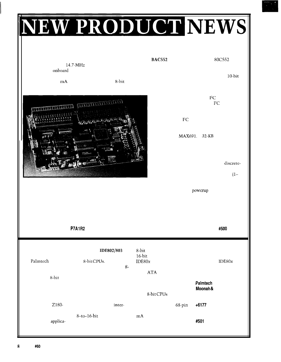
Sylva Energy Systems introduces a low-cost, full-featured BASIC-programmable controller board suited for data
logging, home automation, and industrial-control applications. The
controller uses a Philips
microcontroller with a
clock and is packaged on a 9” x 6” fully socketed board. The controller is applica-
tion ready with
I/O and screw-terminal plug-on connectors.
The controller provides ten 5-A relay outputs, three LED outputs, sixteen optoisolated DC inputs, eight
analog inputs (4-20
or high impedance), two
analog outputs (O-5 V), and an RS-232 or RS-485 communica-
tions port. As an option, the board may be ordered with an X-10 interface controller, which provides full two-way
power-line communications ability.
System expansion via the
bus offers up
to 224 additional I/O points. An
operating
system provides full master/slave communica-
tions between multiple BAC controllers inter-
connected with
bus extenders.
The user BASIC program resides in approxi-
mately 29.4 KB of SRAM, backed by a lithium
battery and a
A
EPROM socket
is available for permanent application program
storage. A BASIC command generates an Intel
hex file of the program in SRAM for EPROM
programming. Full floating-point BASIC is
expanded with statements supporting
I/O-control-based applications. Interrupt sources
include 8 of the 16 inputs, timer interrupt
65,535 s) and a communications interrupt.
Enhanced embedded controller functions include a system watchdog timer, real-time clock/calendar module,
power-loss-duration calculation, warm-or-cold-boot determination, auto-program load on
or reset, error
trapping, and a queued P R I NT statement for improved BASIC execution speed.
The BAC552 controller sells for $299.95 U.S. with a comprehensive user’s manual and the X-10 controller
option.
Sylva Energy Systems
519 Richard St.
Thunder Bay, ON
l
Canada
l
(807) 683-6795
l
Fax: (807) 683-6485
IDE/PARALLEL PORT
The PT
are
bytes rather than 256
chip is a speaker or
INTERFACE
single-chip IDE interfaces
words. The PT
general-purpose output.
announces
for
The chips
accepts any IDE
The PT
sells
two new interface chips
incorporate an additional
drive conforming to the
for approximately $41 in
that connect IDE (hard
bit unidirectional or
CAM
standard and
single quantities.
disk) drives to
bidirectional parallel port
does not require external
processors using a
plus 10 (11 for the IDE803)
buffering to the drive or
minimum of space while
handshake or extra I/O lines
printer. It can be coupled to
Will St.
providing additional I/O
suitable for a printer port.
most
with little
Boulia, QLD 4829
and interrupts. Originally
The chips also include a
or no extra glue logic. The
Australia
developed for a
controller for three
chip is available in a
463-l 09
powered single-board
rupts (two for the ‘803). The
PLCC package, requires 100
Fax: t6177 463-l 98
computer, the chips have
data conversion
at 5 V, and adds only 75
a multitude of
is fully transparent with an
ns to the IDE drive access
tions.
IDE sector accessed as 512
time. Also included on the
Issue
July 1995
Circuit Cellar INK
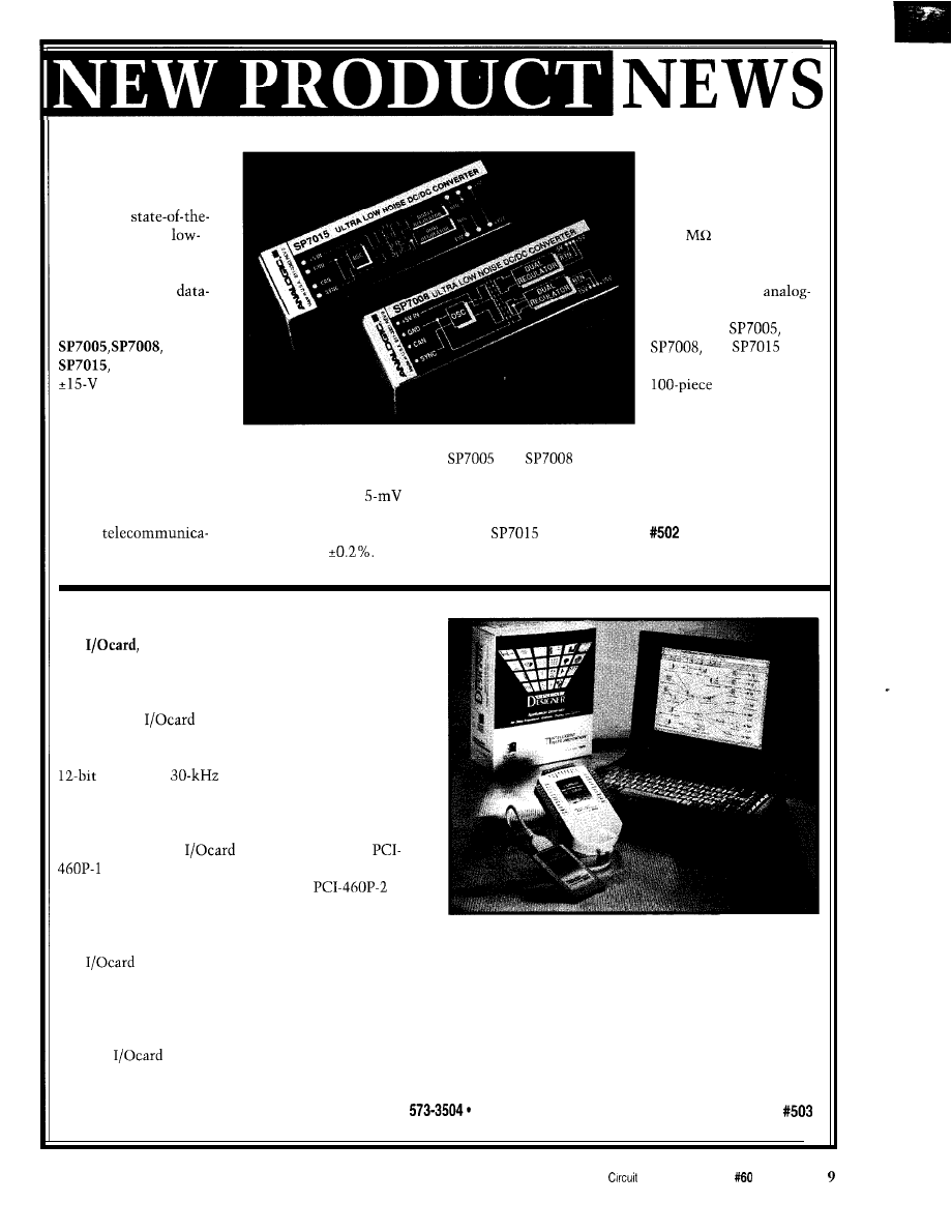
LOW-NOISE DC/DC
product is packaged in a
CONVERTER
1” x 3” x 0.5” fully
Analogic announces
shielded module with
a family of
input-to-output isolation
art exceptionally
of 10
and 500 VRMS.
noise DC/DC converters
An optional sync input is
designed specifically for
available to blank
high-performance
switching during
acquisition applications.
to-digital conversion.
The family, models
Models
and
and
are
provides isolated
priced at $148.50 each in
and +5-V analog
quantities.
supplies from a +5-V
input and has excellent
Analogic Corp.
line-and-load regulation.
8 Centennial Dr.
In addition to data
This family of DC/DC
and
offer
Peabody, MA 01960
acquisition, these
converters features low
additional -6-V and -5-V
(508) 977-3000 Ext. 2170
converters can be used
noise and ripple of
supplies, respectively, and
Fax: (617) 245-1274
in mixed signal circuits
peak-to-peak under a full
provide 6 W of power.
and in
load with a line-and-load
Model
supplies up
tions.
regulation of
Models
to 6.75 W of power. Each
PORTABLE DATA ACQUISITION SYSTEM
a portable data acquisition system for the
PCMCIA bus, has been launched by Intelligent Instru-
mentation. Designed for notebook PCs, the system
requires only 1 W of power, making it ideal for remote
applications.
connects to a PCMCIA type II slot
and consists of a PC card and a termination pad.
The card features 8 differential analog inputs with
resolution,
throughput, and external
triggering. Gains and input ranges are software select-
able. Both unipolar and bipolar input ranges are avail-
able.
Two models of
are available. Model
provides gains of 1, 10, 100, and 1000 for ex-
tremely low-level signal measurement.
provides gains of 1, 2, 4, and 8. The system also features
four TTL inputs, four TTL outputs, cold-junction
compensation for direct thermocouple connection, and a voltage-reference output for powering sensors
is fully supported by Visual Designer, Intelligent Instrumentation’s Windows-based application-genera.
tor software. Users can easily develop their own applications by drawing block diagrams (flowgrams) rather than
coding the applications with a language such as C, Pascal, or BASIC. Sliders, switches, numeric inputs, and user
prompts control the execution of the application. Displays include fully customizable plots, instrument panels, and
control panels.
The
portable data acquisition system sells for $595. Additional termination pads art available for $225.
Intelligent Instrumentation, Inc.
6550 S. Bay Colony Dr., MS130
l
Tucson, AZ 85706
l
(520)
Fax: (520) 573-0522
Cellar INK
Issue
July 1995
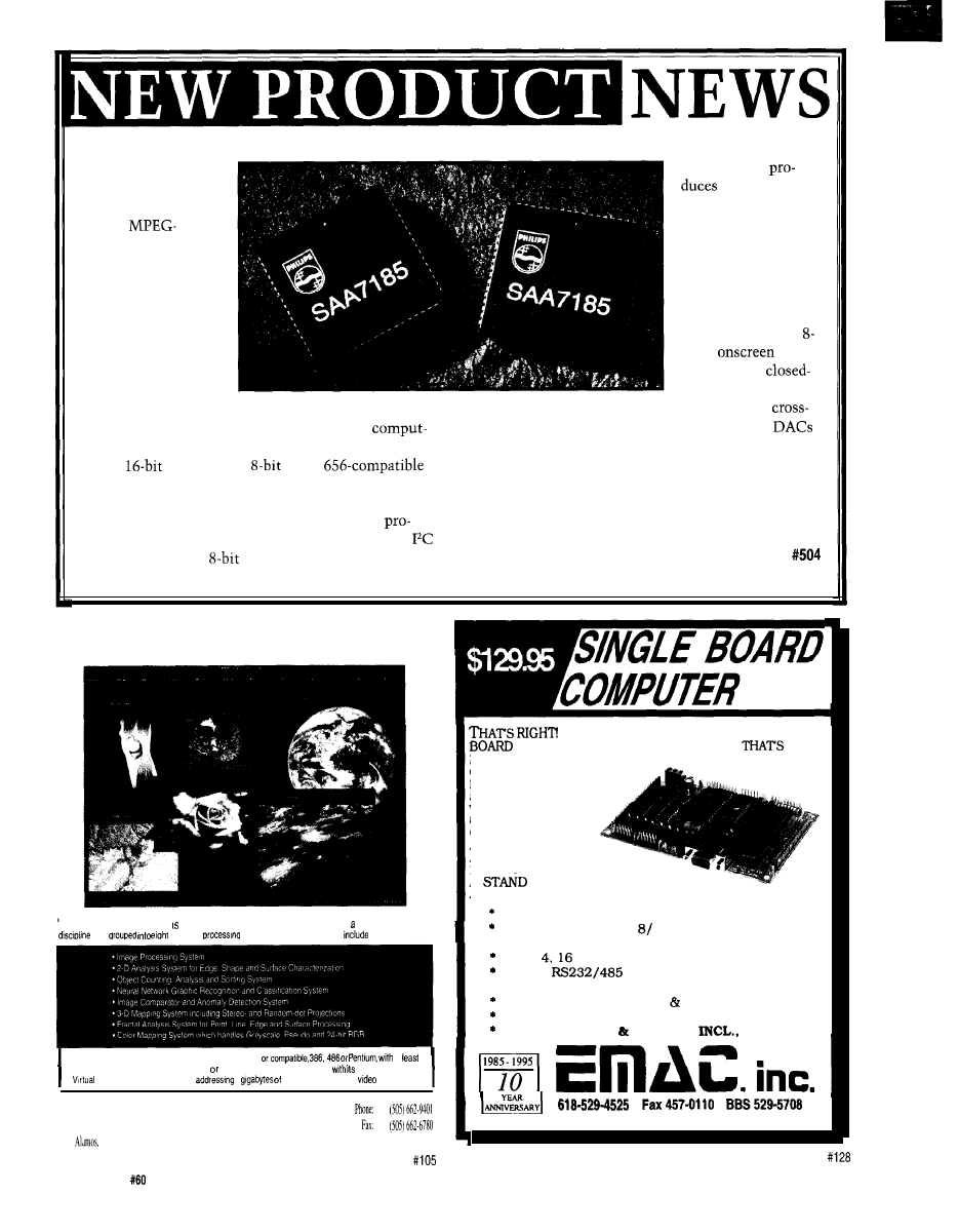
DIGITAL VIDEO
The chip
ENCODER
European PAL
Philips introduces
and either the U.S. or
a digital
Japanese version of
compatible video
the NTSC signal.
encoder. The
NTSC-M and PAL
SAA7185
encodes
B/G standards and
digital YUV data to an
substandards are
NTSC or PAL CVBS
supported. The SAA
and S-video analog
7185 also provides
signal to be displayed
color
display
on a TV or recorded
and provides
on a VCR. The
caption encoding. The
SAA7185 is designed
chip contains
for use in video-processing equipment such as
color-reduction circuitry and IO-bit oversampled
ers, video servers, and video CD players. Because it
to improve image quality.
accepts
YUV data or
CCIR
The SAA7185, in 68-pin PLCC packages, sells for
YUV data in MPEG format, it is ideal for CD playback in
less than $7 in volume.
PCS.
The SAA7 185 is a highly flexible and easily
Philips Semiconductors
grammable 5-V CMOS device. It is controlled via an
811 E. Arques Ave.
l
Sunnyvale, CA 94088-3409
serial interface or an
microprocessor port and
(408) 991-3737
l
Fax: (708) 635-8493
can be synchronized as master or slave to external devices.
A Serious Imaging Solution
IMPACT Professional a complete
image analysis system that Includes broad range of cross-
tools
separate
environments. These modules
SYSTEM REQUIREMENTS:
PC/AT
at
16 MB of RAM and a hard disk DOS 3.1 higher Uses a flat memory model
own extender and
Memory Manager capable of
4
memory A super VGA
card
TARDIS Systems
PO.
Box 1251
FREE DEMO
Los
NM 87544 U S.A.
Technical
Support: (505)
662-5623
10
Issue
July 1995
Circuit Cellar INK
$129.95
FOR A FULL FEATURED SINGLE
COMPUTER FROM THE COMPANY
BEEN
BUILDING SBC’S SINCE
1985. THIS BOARD
COMES READY TO
USE
FEATURING THE NEW
80535 PROCESSOR
W H I C H I S
6051 C O D E
COMPATIBLE.
ADD A KEYPAD
AND AN LCD
DISPLAY AND YOU HAVE
A
ALONE CONTROLLER WITH
ANALOG AND DIGITAL I/O. OTHER FEATURES INCLUDE:
UP TO 24 PROGRAMMABLE DIGITAL I/O LINES
8 CHANNELS OF FAST 10 BIT A/D
l
OPTIONAL 4 CHANNEL, 8 BIT D/A
UP TO
BIT TIMER/COUNTERS WITH PWM
UP TO 3
SERIAL PORTS
l
BACKLIT CAPABLE LCD INTERFACE
OPTIONAL 16 KEY KEYPAD INTERFACE
160K OF MEMORY SPACE, 64K INCLUDED
8051 ASSEMBLER MONITOR
BASIC OPT.
P.O. BOX
2042, CARBONDALE, IL 62902
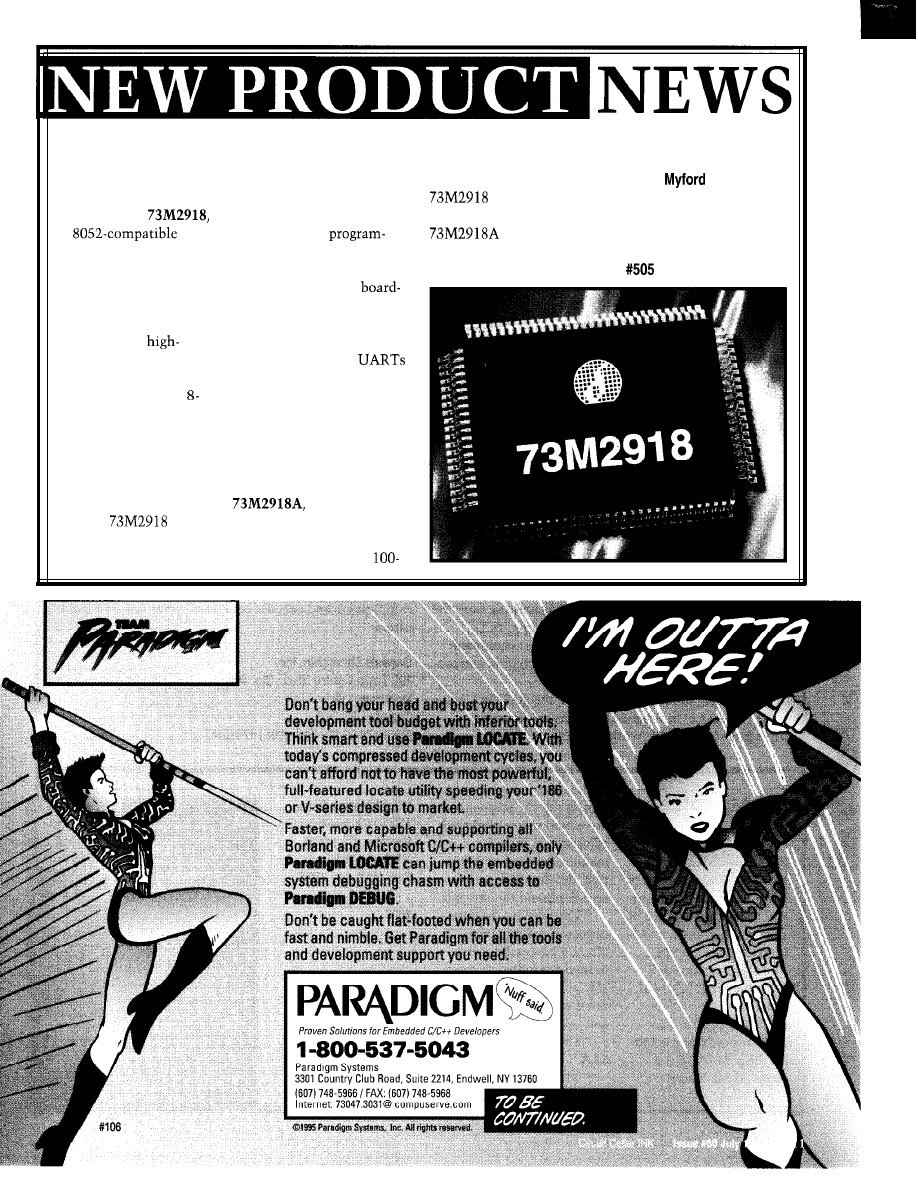
PLUG-AND-PLAY
along with the registers and
lead QFP package. In
Silicon Systems
MICROCONTROLLER
hardware required to
quantities of 1000, the
14351
Rd.
Silicon Systems
facilitate Plug and Play. The
is priced at $10.24
Tustin, CA 92680
introduces the
device features 32 pins of
and the high-speed
(714) 573-6200
an
additional user
at $14.92.
Fax: (714) 573-6914
microcontroller with
mable I/O. Programmable
virtual 550 UART and
bank- and chip-select logic
built-in hardware which
supports the emerging
Plug-and-Play ISA
standard. This
performance microcon-
troller has all the
attributes of an 8052
bit microprocessor,
including instruction
cycle time, UART,
timers, interrupts, 256
bytes of RAM, and
programmable I/O.
The
also
includes an HDLC
packet-generation unit
reduces the need for
level glue logic. The unit
has two buffered clock
outputs to support periph-
eral devices such as
and modems and two
general-purpose input pins
with programmable wake-
up capability.
The device operates at a
speed of 33 MHz at 5 V. An
optional version, the
operates at 44
MHz for high-speed applica-
tions. The device is offered
in a small-form-factor
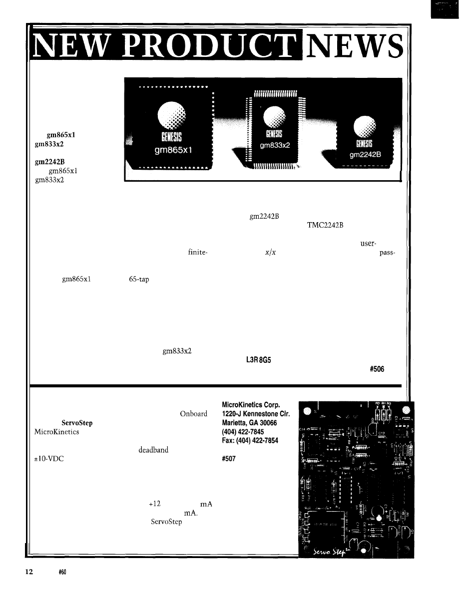
VIDEO/IMAGE DSP
CHIPS
Genesis Microchip
announces full-volume
production of three
video/image DSP chips:
the
and
video/image
resizing engines and the
half-band filter.
The
and
provide a
revolutionary break-
through in image-resizing technology and are part of the
Acuity Resizing series of real-time, 2D filtering engines.
Acuity Resizing devices produce the high-quality scaled
images while minimizing the undesirable aliasing,
artifacts, and distortion often created during digital-video
scaling. Both chips use patented algorithms and architec-
tures and implement advanced interpolation and
impulse-response (FIR) filtering. In reduction mode, all
memory required for FIR filtering is provided on-chip.
The
offers up to
vertical and
horizontal filtering independently in both directions. As
a top-of-the-line part, it produces the highest quality
resized images possible. Applications benefiting from the
chip’s performance include medical imaging, LCD
projection systems, and high-end broadcast equipment
which can take advantage of the chip’s dynamic horizon-
tal resizing for special effects.
For more cost-sensitive systems, the
(an up
to 33-tap device) is designed for many applications
including videographic workstations, multimedia
systems, and projection and scan-conversion equipment.
Both chips perform shrink-and-zoom operations.
The
half-band filter is fully compatible
with the industry-standard
part and offers
more features at significantly less power and substan-
tially less cost. Its unique features include a
selectable sin
compensating filter and a handy
through mode. Constant data latency, available in all
operating modes, is also available. Half-band filters
double or halve digital-signal sampling rates and simplify
ADC and DAC subsystem design. Applications ranging
from broadcast and teleconferencing systems to digital
compression and encoder equipment often use half-band
filters.
Genesis Microchip, Inc.
200 Town Centre Blvd., Ste. 400
Markham, ON
Canada
(905) 470-2742
l
Fax: (905) 470-2447
STEPPER MOTOR
CONTROLLER
The
from
controls
the speed and direction of
a stepper motor from any
signal source or
from a single slide or
rotary potentiometer.
The step output is a
frequency that is propor-
tional to the magnitude
of the input. The direc-
tion output is dependent
on the polarity of the
input signal. These
signals run the stepper
driver and motor.
adjustments include
maximum speed, accelera-
tion, deceleration, and a
zero
adjustment.
The outputs are open
collector, making them
directly compatible with
industry-standard drivers.
The power supply require-
ment is
VDC at 100
and -12 VDC at 50
The
sells for
$199.
Issue July 1995
Circuit Cellar INK
The Use of Color in
Scientific Visualization
Virtual Reality
Position Tracking
Digital Video Resizing
and Compression
A
Motor Speed Controller
Mike Bailey
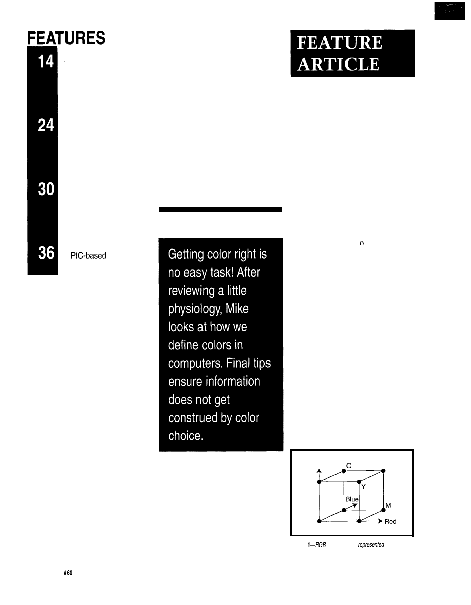
The Use of Color in
Scientific Visualization
0
some, a
discussion of color
in scientific visual-
ization seems unneces-
sary. But, experience shows that some
ways of using color communicate
information more effectively than
others. Used incorrectly, color de-
tracts, providing less information than
if it had not been used at all.
This article does not explain ev-
erything there is to know about color
physics and human vision. Instead,
after an overview of some these as-
pects, I go right to the qualitative is-
sues of what color is and how it should
be handled.
COLOR FREQUENCIES AND
WAVELENGTHS
The electromagnetic spectrum is
infinitely large. At the low frequency
Green
White
Black
Figure
co/or space is
as an
orthogonal axes.
14
Issue July 1995
Circuit Cellar
INK
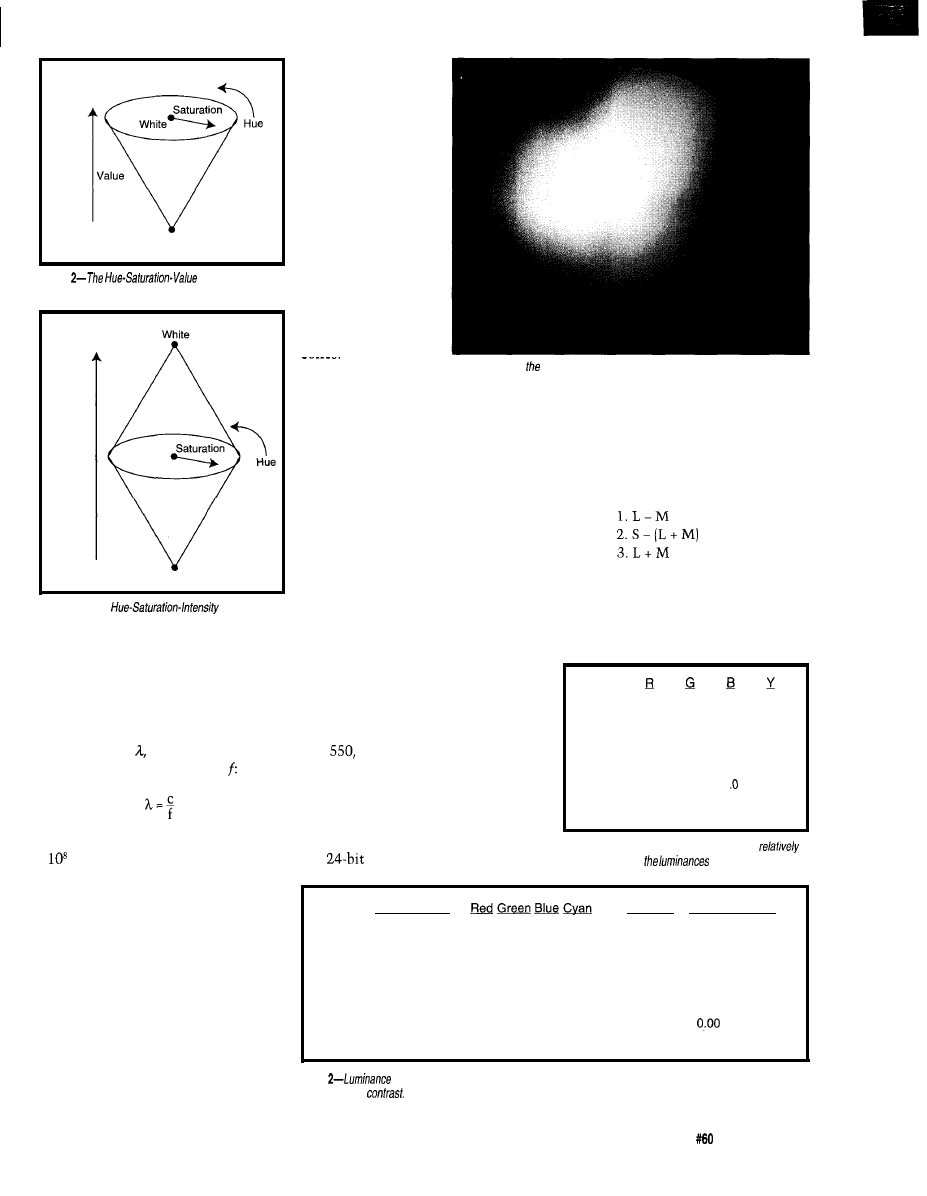
Black
Figure
color cone is
easier for
humans to understand and work with.
Intensity
Black
Figure
3-/n the
cone, color
intensity is also accounted for.
end, it contains radio waves and mi-
crowaves. At the high end, it contains
x-rays and gamma rays. Rather than
speak of frequency, electromagnetic
waves are usually discussed in terms
of wavelength, which is inversely
proportional to the frequency,
where c equals the speed of light (i.e., 3
x
m/s). Our eyes happen to be sen-
sitive to the range of wavelengths
within 380-780 nm. We see the long
wavelengths around 780 nm as red and
the short wavelengths around 380 nm
as deep blue-purple.
THE EYE
The human eye is a marvelous
input device, designed to meet a cer-
tain set of everyday demands. Like
many parts of the human body, the eye
is not a single component. Rather, it
has several parts, each with its own
area of specializa-
tion.
Rods are retinal
sensors that detect
grayscale and low
levels of light. A
typical human retina
has approximately
115 million rods,
mostly sensitive in
the 500 nm (-green)
range. Because there
are so many, rods are
much better at de-
tecting high spatial
frequencies than
cones.
Interestingly,
Photo l--Here’s
fop circle of the Hue-Saturation-Value color cone.
rods are concen-
trated near the retina’s periphery. Pe-
ripheral vision is therefore much more
sensitive to small light changes than
straight-on vision. As a result, some
people detect CRT flicker only out of
the corner of their eye. Straight-on, the
flicker is no longer there.
Cones enable us to see color. Ap-
proximately 8 million cones concen-
trate near the center of the retina (the
fovea), where their density is about
150,000 per square millimeter. Thus,
color vision is far more sensitive to
objects directly in front of us.
Cones are categorized by the
wavelengths they are sensitive to.
Low, medium, and high frequencies
are viewed by L, M, and H cones,
which achieve maximum sensitivity at
570,
and 440 nm, respectively.
These wavelengths loosely correspond
to the red, green, and blue portions of
the spectrum.
It would be nice if the brain ap-
proximated red, green, and blue signals
in a
(or more) frame buffer. Un-
fortunately, it is more complicated
than that.
Three signals do go to the brain
but as combinations of the L, M, and H
cone signals. Specifically, they are:
If we permit ourselves the luxury of
relating L, M, and H to R, G, and B
(even though this is not exactly right),
the three signals become:
Black
0.0
0.0
0.0
0.00
White
1.0
1.0
1.0
1 .oo
Red
1.0
0.0
0.0
0.30
Green
0.0
1.0
0.0
0.59
Blue
0.0
0.0
1.0
0.11
Cyan
0.0
1.0
1.0
0.70
Magenta
1 .O
0.0
1
0.41
Orange
1.0
0.5
0.0
0.60
Yellow
1.0
1.0
0.0
0.89
Table
l-Using the luminance equation, it is
easy to defermine
of standard colors.
B l a c k W h i t e
M a a e n t a O r a n a e Y e l l o w
Black
0.00
1.00
0.30
0.59
0.11
0.70
0.41
0.60
0.89
White
1 .oo
0.00
0.70
0.41
0.89
0.30
0.59
0.41
0.11
Red
0.30
0.70
0.00
0.29
0.19
0.40
0.11
0.30
0.59
Green
0.59
0.41
0.29
0.00
0.48
0.11
0.18
0.01
0.30
Blue
0.11
0.89
0.19
0.48
0.00
0.59
0.30
0.49
0.78
Cyan
0.70
0.30
0.40
0.11
0.59
0.00
0.29
0.11
0.19
Magenta
0.41
0.59
0.11
0.18
0.30
0.29
0.00
0.19
0.48
Orange
0.60
0.41
0.30
0.01
0.49
0.11
0.19
0.30
Yellow
0.89
0.11
0.59
0.30
0.78
0.19
0.48
0.30
0.00
Table
differences offer
a scientific measurement of contrast. The greater the luminance difference,
the greater fhe
A good contrast is 0.40 luminance difference.
Circuit Cellar INK
Issue
July 1995
15
1.
red-green
2. blue-(red+green)
3. red+green
If yellow is substituted for
red+green, the second signal
becomes blue-yellow. Thus,
the eye-brain system distin-
guishes chromaticity by the
red/green and blue/yellow
difference.
Knowing that blue only
contributes about 11% to
the overall appearance of
brightness of a color, color
scientists treat the third
quantity
as
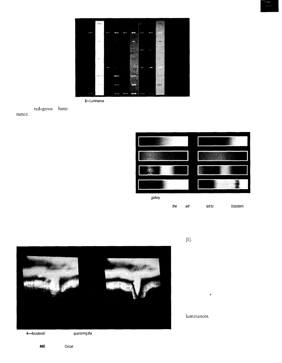
Photo
differences shown in Table 2 fake on a clearer meaning when
shown graphically.
So, the third signal becomes
overall luminance.
The red-green signal is where
most color deficiency occurs. For ex-
ample, people with red/green color
blindness do not correctly produce the
red-green signal. Although blue, yel-
low, and overall luminance is under-
stood, the person cannot determine if
something is more red than green or
vice versa.
DEFINING COLOR DIGITALLY
Too often, we ask computers for
color in a way suitable to them: red,
green, blue (RGB). Integers are fed to
the digital-to-analog converters of the
color guns.
This method uses a rectilinear
color space where red, green, and blue
are the principal axes. Black is at the
origin and white is at the other end of
the major diagonal. As Figure
1
illus-
trates, the complementary colors of
component, the color moves
closer to white and satura-
tion decreases. Decreasing
one or two components
decreases the value or
brightness. Traveling around
the circumference changes
the hue. Photo
1 shows the
top circle of the HSV color
cone.
The Hue-Saturation-
Intensity system is another
fairly easy way to specify
color (see Figure 3). The two
cones join at their bases
with black being at the
bottom tip and white at the
cyan, magenta, and yellow are at the
remaining corners.
Although this is convenient for
computers, hu-
mans don’t think
this way. It’s
top. Equatorial colors have at most
two components (e.g., red or red +
green = yellow). Colors with three
easier to specify
color with the
Hue-Saturation-
Value (HSV) sys-
tem, an inverted
cone shown in
Figure 2. Black is
at the bottom tip
and white forms
the base’s center.
The circumfer-
ence includes
colors with at
Photo 3-A
of color interpolation functions. Grayscale, intensify, saturation,
two-color, rainbow, rainbow with luminance modifications, heated
object, and optimal
are represented
starting in upper and moving right and fop
most two components. Colors with
three components are found within the
cone’s volume.
If you start on the base circumfer-
ence and increase the missing color
Photo
meaning is added by
colors in a visualization display.
16
Issue
July 1995
Cellar INK
components are found in the volume
of the double cone.
Doing a conversion from HSV or
HSI to RGB is reasonably straightfor-
ward
THE LUMINANCE EQUATION
When displaying information on
top of other information or a back-
ground (e.g., with text and graphs], it is
important to get good intensity con-
trast. The luminance equation deter-
mines good contrasts:
Y = 0.30 x red 0.59 x green +
0.11 x blue
Table 1 shows standard colors and
their
Individual color
component intensities have been nor-
malized from 0.0 to 1 .O, instead of the
more familiar O-255.
Photo
5-/n the first
photo, arrows indicate the
direction of the magnetic
field. The second photo
shows the same arrows
with co/or added using a
rainbow scale keyed from
the
sine of the arrow
angle.
Table 2 offers a first-order approxi-
mation of contrast by taking the differ-
ence between the
of a
foreground and background color. The
greater the Aluminance, the greater the
apparent contrast. A good threshold
value for contrast is a Aluminance of
about 0.40. This number, of course,
varies between people and lighting
conditions. Photo 2 depicts a color
version of Table 2.
As the luminance equation im-
plies, RGB color space is not perceptu-
ally uniform. A green of
looks
brighter than a blue of
Neither the HSV nor the HSI color
space is perceptually uniform either.
On the circumference of the color
cone, green looks brighter than blue. If
perceptual uniformity is important, it
is better to ask for color in the CIELAB
or CIELUV color space.
COLOR ATTRIBUTES
In choosing color, be aware of
established cultural or professional
meanings for certain colors. Any visu-
alization portraying set qualities is less
effective if it fights the colors most
viewers associate with these qualities.
For example, red indicates stop,
on, off, hot, dangerous, high stress,
oxygen, shallow, and money loss, de-
pending on the application.
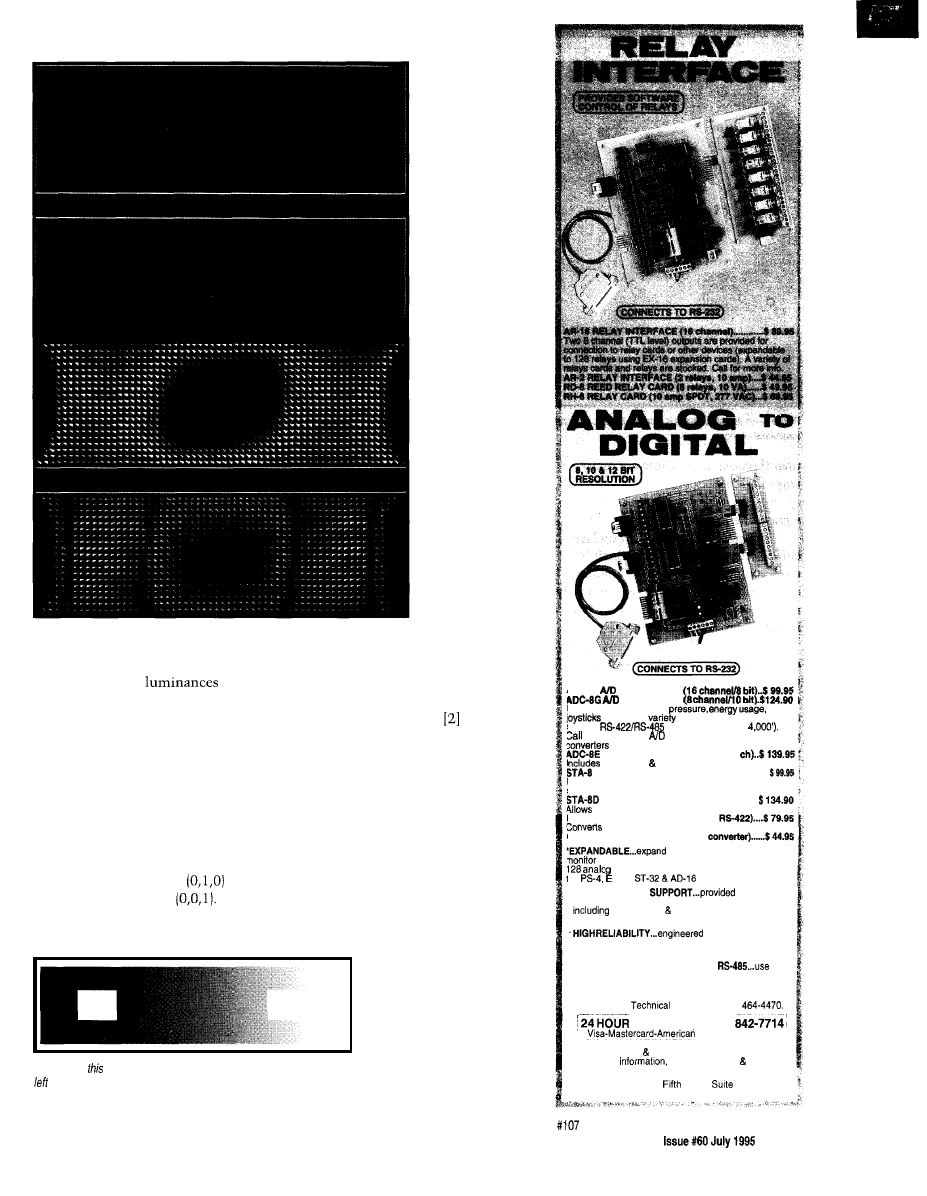
Figure 4-/n
simultaneous contrast illusion, the white square on the
looks lighter than the white square on the right In fact, fhey are both
the same. On/y the surrounding colors differ.
COLOR
INTERPOLATION
Just as color repre-
sents ranges of scalar val-
ues such as temperature or
stress, good ways must be
chosen to interpolate col-
ors in an intuitive and
ADC16
CONVERTER’
CONVERTER*
Input voltage, amperage,
and a wide
of other types of analog
signals.
available (lengths to
for info on other
configurations and 12 bii
(terminal block and cable sold separately).
TEMPERATURE INTERFACE’ (6
term. block 8 temp. sensors (-40’ to 146’ F).
DIGITAL INTERFACE’@ channel) . . . . . . . . .
Input on/off status of relays, switches, HVAC equipment.
security devices, smoke detectors, and other devices.
TOUCH TONE INTERFACE* . . . . . . . . . . . . . . . .
callers to select control functions from any phone.
PS-4 PORT SELECTOR (4 channels
an W-232 port into 4 selectable RS-422 ports.
CO-498 (RS-232 to RS-4221RS-495
your interface to control and
up to 512 relays, up to 576 digital inputs, up to
he
inputs or up to 128 temperature inputs using
X-16,
expansion cards.
*FULL TECHNICAL
over the
telephone by our staff. Technical reference & disk
test software programming examples in
Basic, C and assembly are provided with each order.
for continuous 24
hour industrial applications with 10 years of proven
performance in the energy management field.
*CONNECTS TO RS-232, RS-422 or
with
IBM and compatibles, Mac and most computers. All
standard baud rates and protocols (50 to 19,200 baud)
Use our 900 number to order FREE INFORMATION
PACKET.
information (614)
ORDER LINE (800)
Express-COD
International Domestic FAX (614) 464-9656
Use for
technical support orders.
ELECTRONIC ENERGY CONTROL, INC.
380 South
Street,
604
Columbus, Ohio 43215.5436
Circuit Cellar
INK
17
Photo
this
simultaneous contrast illusion, you can see how red, green, and blue change as background
luminance
changes.
unambiguous way. There are many
ways to do this.
tion even though it is no more
cant than any other color.
Grayscale’s major disadvantage is
l
grayscale interpolation
that the eye only sees a limited
The simplest way to interpolate
ber of shades per hue. Multiple hues
color is through grayscale, which is
offer more scalar values.
easy to produce-mix equal amounts
of red, green, and blue. However, many
l
HSV and HSI (rainbow) interpolation
resist grayscale interpolation because
To get a reasonable color range for
it is not sufficiently flashy.
displaying scalar values, interpolate
But, grayscale interpolation has a
hues in the HSV or HSI color spaces.
major advantage. It faithfully
You can hold the saturation and value
a range of scalar values without
or intensity constant and linearly
assigning any preconceived ideas about
terpolate the hue.
the order. Physicians using computer
Typically, this interpolation
graphics dislike color interpolation for
gins at blue, passes through green, and
x-ray photographs since color can
ends at red. The blue-green-red path is
ply meaning where there is none. For
popular because it approximates the
example, a bright red area draws
color order of the electromagnetic
spectrum that everyone sees in a rain-
bow. The direction blue-green-red or
red-green-blue is determined by the
inherent meaning of those colors in
that particular application.
However, this method has prob-
lems. The best-looking colors on the
monitor are fully saturated, but satu-
rated colors cause problems with
hardcopy and video devices. Typically,
saturation should be held at 0.80 or
less during the interpolation.
As well, different hues are per-
ceived to have different intensities.
Yellow is seen as the brightest, most
important color (not red). If this distor-
tion is a problem, use the luminance
equation with the HSV or HSI equa-
tions to achieve a constant luminance
instead of constant value or intensity.
This interpolation method also
leaves large ranges of scalar values
mapped to similarly perceived colors.
You can make this clearer by having
every nth scalar value map to black or
white, creating contour lines to distin-
guish scalar values. This technique is
especially effective in dynamic dis-
plays, but double check that you don’t
accidentally add meaning through
color discontinuities.
l
saturation interpolation
This method gives a color scale
from unsaturated gray to a fully satu-
rated color and is convenient when the
hue carries other informational mean-
ing and cannot be modulated.
Fully saturated areas are most
colorful and draw most of our atten-
tion. Map the most important scalar
Photo
of
simultaneous contrast, identical colon which are further apart
are more likely appear different. Although if is
easy identify colored
square’s
on right in first photo, if is
impossible in second.
1 8
Issue
July 1995
Circuit Cellar INK
values here. For example, information
on forest fires could overlay an exist-
ing colored map. If saturation is in-
versely proportional to the amount of
burn, severely burned areas are gray or
nearly gray and untouched areas retain
their full map color.
l
intensity interpolation
You can also hold the hue and
saturation constant to interpolate the
intensity, which produces a color scale
running from a dark version of a color
to a light version of the same color
(e.g., black to white).
This method is seldom used in
scientific visualization because too
often the difference in intensity is
mistaken for 3D light-source shading
images with significant intensity
variations tend to look 3D).
Use this interpolation method
carefully and only with good reason!
l
two-color interpolation
Sometimes, it’s an advantage to
show the variation of a scalar variable
by interpolating between two colors.
For example, with a terrain map, a
forest (green) and a desert (brown) uses
natural colors to correspond to scalar
values. Interpolating the brown and
green indicates forested land.
l
heated-object color scale
When an object is heated, its color
passes through a range of frequencies
from red to yellow to white otherwise
known as the
heated-object color
curve.
is used, among other things,
to determine the temperature and
motion of stars. That range of colors
quite effectively encodes scalar infor-
mation
l
optimal color scales
Levkowitz and Herman also
use a color scale passing through red,
yellow, and light blue while moving
from black to white. This color scale
optimizes the maximum number of
perceptually equal changes from black
to white and distinguishes the maxi-
mum number of scalar values in a
many-valued image such as a CAT
scan or satellite image.
Photo 3 shows a gallery of color
interpolation functions. However, it is
Perceived
intensity
Figure
the
banding illusion, the eye
sharpens each edge by making each band appear
brighter on the left and dimmer on the right. fact, the
intensity is constant within each band.
sometimes necessary to interrupt the
continuity of color interpolation be-
cause your system has only 256 colors
or you need to add black or white col-
ors to create contour lines. In either
case, a less-than-continuous change of
colors might be interpreted as a dra-
matic change in the scalar values.
Photo shows what can happen
when 16.7 million colors are quantized
to 256. Note that the boundary be-
tween scalar values in the quantized
image appears much sharper than it
really is.
REINFORCING INFORMATION
Color has an enormous impact
on the way people perceive informa-
tion. Here are some principles that
you need to bear in mind while using
color.
l
color indicates patterns
Because color can be perceived as
a global pattern, using color to rein-
force smaller details often reveals new
patterns in the data.
For example, a large vector field
could be displayed as a collection of
arrows where each arrow’s size and
direction shows the value of the vector
field at that point. It is difficult to look
at such a display and understand the
overall pattern of vector magnitudes.
Color coding the vectors (e.g., low
velocity marks one end of the color
Byte Craft
C Compilers of choice
l
Fast, efficient optimizing compilers
l
Chip specific
.
assembler
l
Integrated Development Environment
l
Linker, libraries
Optimizing C compilers for your single
chip designs.
We respond to your C
compiler needs!
Byte Craft Limited
421 King St. N., Waterloo, Ontario
CANADA
(519) 888-6911
Fax: (519) 746-6751
BBS: (519) 888-76;
Circuit Cellar INK
Issue
July 1995
1 9

spectrum and high velocity the other)
reveals more of the overall pattern.
Photo enables viewers to better
understand the distribution and direc-
tion of a magnetic field.
l
limit the number of colors
If viewers need to discern informa-
tion quickly or for absolute color dis-
crimination, limit the total number of
colors. Too many colors cause a viewer
to overanalyze the information (at
best) or get it wrong (at worst). Studies
show that approximately seven colors
is the optimal number for easy memo-
rization and discernment.
l
surrounding change colors
Simultaneous contrast is a
known effect which states that our
perception of a color is tainted by sur-
rounding colors.
In Figure 4, the white square on
the left looks lighter than the white
square on the right. Photo 6 shows
another example of the simultaneous
contrast illusion. Here, you can see
how red, green, and blue change as
background luminance changes. These
examples reinforce the argument for
using fewer colors when quickly dis-
crimination is needed.
l
compare adjacent colors
Because of simultaneous contrast,
the farther apart two colors are spa-
tially, the more likely it is that inter-
vening colors cause them to appear
different, even if they are identical.
Photo 7 shows a pathological ex-
ample of this. A colored square is
meant to be matched to one of the
squares on the right. With a solid back-
ground, it is not hard to do. In the
second photo, the background has been
replaced with one of changing color.
The differences in background, com-
bined with the distance between the
colors to be matched, make compari-
son more difficult.
l
colors change with area size
Perception of a color depends on
its area. In particular, our ability to
discriminate colors diminishes with
size. This is especially true with satu-
rated blues, which should be avoided
for small objects.
20
Issue July
1995
Circuit Cellar INK
Color standards know about this
effect and thus fix the size of the color
area presented to test subjects. Typi-
cally, this is around 2” of subtended
arc (2” is about how large your thumb
appears at the end of your outstretched
arm. A full moon subtends an arc of
about 0.5”).
brighter on the left and dimmer on the
right. We perceive a
effect as
would be seen in a Greek column.
If you don’t believe that percep-
tion of color changes with the size of
the colored area, remember the paint
swatch you liked and the painted wall
you didn’t.
Mach banding also shows up when
smooth-shading polygons. Even
though the intensity is interpolated
within each polygon, at the polygon
borders there is a first-derivative dis-
continuity in intensity so that bright
or dark lines appear along polygon
boundaries.
. color changes with ambient light
Since
banding interferes
with the eye’s ability to discriminate
intensity differences, don’t expect
crucial decisions to be made based on
High ambient light tends
to desaturate the appearance
of colors, particularly yel-
lows.
l
the ability to discriminate
colors changes with age
You’re not going to
change this much-just use
fewer colors.
l
beware of afterimage
anomaly
With all-green calli-
graphic CRTs, there was a
phenomenon known as pink
eye.
After staring at a green
screen for a while, the victim
would rise, look around, and
see nothing but pink. This
afterimage of a particular
color is determined by its
Figure 6-The interior
of the
diagram represents the
color set
that humans perceive.
complement in either the Red-Green
displays where there is abrupt inten-
or Blue-Yellow pair.
sity or intensity-slope changes.
While this is fun to experiment
with, it can seriously jeopardize con-
clusions in scientific visualization and
reinforces the need for fewer colors.
The more difference between display
colors, the less likely an afterimage
will cause one color to be mistaken for
another.
l
be aware of color-recognition defi-
ciencies
l
beware the anomaly of
banding
The human visual system tries to
automatically increase edge sharpness.
Nowhere is this more obvious than in
a series of intensity bands shown in
Figure 5.
The phrase “color blindness” is a
misnomer, better described as a
recognition deficiency. Many people
(-10% Caucasian men, -4%
Caucasian men, and -0.5% women)
have some form of color-recognition
deficiency.
The most common deficiency is
the inability to discern red versus
green. It is a good rule of thumb to
redundantly display important infor-
mation (e.g., colored and outlined).
Even though a spectracolorimeter
shows that the intensity is constant
within each band, the eye sharpens
each edge by making each band appear
Because many have problems
recognizing colors quickly, don’t have
color recognition as the single point of
failure in crucial operations of
tive systems. Also, because
hardcopies get photocopied, color
information is eliminated. Dupli-
cate information through shape,
fill pattern, outline pattern, out-
line thickness, character strings,
fonts (including bold and italics),
and symbols.
l
outline boundaries
Two colored areas adjacent to
each other is common in scien-
tific visualization (e.g., when two
countries abut on a map or areas
of stress concentration are de-
picted contiguously).
Usually, the shape of the
border is important since cones,
which detect color, are not good
at detecting boundaries. Rods
detect boundaries well, especially
if the line between adjacent col-
ors is black or white.
0 . 8 0
0 . 6 0
Figure
color gamut for a Silicon Graphics monitor, the white
of the monitor
is more blue than the overall white point
Less-saturated blues work
much better because other wave-
lengths are mixed in, thus stimu-
lating the more effective M- and
L-type cones.
l
avoid mixing saturated reds and
blues together
Do not place saturated reds
and blues next to each other. In
the eye, low color frequencies
(reds) focus in front of high fre-
quencies (blues). The difference
in focal locations, known as
mostereopsis, appears to the eye
as a change in depth. The red
portion appears closer to the
viewer than does the blue por-
tion.
In advertising, this effect is
often used to draw attention. In
scientific visualization, however,
sensitivity to blues is reduced. In other
it can be disconcerting. Although the
words, the visual system processes
viewer knows that the entire display is
l
avoid saturated blues for fast-moving
blues less effectively than other colors.
at a single depth, chromostereopsis
items or fine detail
From the luminance equation, we
fights this knowledge.
Only about
of your cones are
know that only about 11% of overall
If reds and blues must be adjacent,
the S-type, which means that your
luminance come from blue.
desaturate them so that other color
CIRCUIT CELLAR KITS
Sonar Ranging Experimenter’s Kit
EEG Biofeedback Brainwave Analyzer
Targeting Ranging Machine Vision
The Circuit Cellar
Ultrasonic Sonar Ranger is based on the
The HAL-4 kit is a complete
sonar ranging circuitry from the Polaroid SX-70 camera system. The
4-channel electroencephalograph (EEG) which
and the original SX-70 have similar performance but the
Sonar
measures a mere
HAL is sensitive enough
Ranger requires far less support circuitry and interface hardware.
to even distinguish different conscious
The
ranging kit consists of a Polaroid
300-V
between concentrated mental activity and
static transducer and ultrasonic ranging electronics board made by Texas
ant daydreaming. HAL gathers all relevent alpha,
Instruments. Sonar Ranger measures ranges of 1.2 inches to 35 feet, has a
beta, and theta brainwave
output when operated on
and easily connects to a parallel
signals within the range of
printer port.
4-20 Hz and presents it in a
serial
digitized
format that
Sonar Ranger kit.
plus shipping
can be easily recorded or
analyzed.
CHECK OUT THE NEW CIRCUIT CELLAR
HAL’s operation is
straightforward. It samples four channels of analog brainwave data 64
HOME CONTROL SYSTEM
times per second and transmits this digitized data serially to a PC at 4800
bps. There, using a Fast Fourier Transform to determine frequency,
amplitude, and phase components, the results are graphically displayed
in real time for each
side of the brain.
HAL-4 kit
plus shipping
Expandable Network
IR Interface
Digital
and
Analog I/O
Remote Displays
X-l Interface
Telephone Interface
Voice
Call and ask about the HCS
l
The
Cellar
Level detector presented as an
example of the
To order the products shown or to receive a catalog,
techniques used
Level detector a
medically approved
no
are made this device, and should not be used for
call:
(203) 875-2751 or fax: (203) 872-2204
purposes. Furthermore, safe use
that HAL be battery operated only’
Circuit Cellar Kits
l
4 Park Street
l
Suite 12
l
Vernon, CT 06066
Circuit Cellar INK
Issue
July 1995
2 1

0 . 6 0
0 . 0 0
0 . 0 0
0 . 2 0
0 . 4 0
0 . 6 0
0 . 8 0
Figure
slides are
before taking the
measurements
so they are viewed in the environment they will most often be seen in.
Thus, this color
gamut is a result of both the
color response and the
projector
light
color bias.
frequencies mix in and the frequency
difference is not as dramatic.
l
do not display high spatial frequen-
cies in color
High spatial frequencies (e.g.,
closely spaced thin parallel lines) are a
lot easier to recognize in black and
white than in color. Rods have higher
spatial discrimination than cones.
COLOR GAMUTS
A color is a color, right? Wrong.
The color a device is asked to
display and the color that comes out
are usually different. The range of
colors that a graphics device is capable
of displaying is referred to as a color
gamut.
Before discussing color gamuts, we
need to introduce the CIE
ity diagram.
Figure 6 shows this dia-
gram which was created in 193 1 by the
Commission Internationale
(CIE) and was the result of experi-
ments in human color vision.
Although it is interesting to delve
into how the graph was created or why
it is the shape it is, the important
thing to know is that the interior of
the graph represents the total color set
humans perceive. The horseshoe repre-
sents the electromagnetic spectrum
from 380 nm (blue) in the lower-left
corner to 520 nm (green) at the top and
22
Issue
July 1995
Circuit Cellar INK
780 nm (red) in the
right corner. The
energy white point lies at
the coordinate (0.33,
0.33). The distance from
the white point measures
saturation, and the angle
around the white point is
considered the hue.
Colors on the outline
of the horseshoe are pure
colors
(i.e., composed of a
single wavelength). The
exception to this rule is
the diagonal straight line
from blue to red, known
as the magenta line. The
line is pictured because
display monitors mix blue
and red to get magenta, so
it is handy to have some
way of showing this, even
though the electromag-
netic spectrum does not.
For the color C in the interior, the
shortest distance to the outline of the
horseshoe produces the color’s domi-
nant wavelength, D. A line through
the white point produces the
color’s complementary color C’.
The biggest color gamut problems
come in subtractive color printing.
Figure 9 shows the color gamut for a
Canon CLC-500 color printer. As you
can see, the color gamut for the
500 is much smaller than that of the
SGI monitor.
The CIE diagram provides a stan-
dard measurement methodology for
comparing color on different devices.
CIE color is measured with an instru-
ment called a spectracolorimeter.
Different devices (CRTs, paper, film)
have different color gam-
uts.
Besides having a smaller gamut,
this example shows the more insidious
problem of color rotation. Lines drawn
from the white point through each of
the two green points show a consider-
able rotation around the white point.
As a result, not only are the saturated
For example, Figure 7
shows the color gamut for
a particular Silicon Graph-
ics monitor (measured by
a Photo Research PR-650
spectracolorimeter
Note that the white of the
monitor (Wm)
is
more
toward the blue part of the
gamut than the overall
white point (W). Monitor
vendors have discovered
what laundry detergent
makers have known for
some time: humans per-
ceive a slightly bluish
white as being more
“white” than pure white.
Obviously, there are
many colors the eye
0 . 8 0
0 . 7 0
0 . 6 0
0 . 5 0
0 . 4 0
0 . 3 0
Figure
9-The biggest problems with co/or gamuts occur in subtractive
color printing. As you can see, there can be quite a difference between
the color gamut of a monitor and a color printer.
that the monitor cannot display,
primarily in the green areas. This prob-
lem is most critical in generating real-
istic images, but in scientific visualiza-
tion, color usually represents some-
thing else.
It does, however, become a major
consideration when moving scientific
visualization images from the monitor
to another display device (e.g., a screen
dump of a monitor display which
sends the RGB values directly to a
slide film recorder). Figure 8 shows the
color gamut of projected slides.
Not surprisingly, Figure 8 shows a
good range of color reproducibility, but
with a distinct bias toward the yellow
portion of the spectrum. This bias is a
result of the yellowish color coming
from the bulb in the projector. This
drift mostly hurts the reproducibility
of blues in the original image.
monitor colors not able to be printed,
but attempting to print them results in
a considerable hue change.
Much work has been done on the
use of color theory to match the colors
of different display devices
and
LIMITATIONS OF NTSC VIDEO
Frequently, scientific visualiza-
tions are recorded to videotape. It
would be nice if this was an automatic
process (i.e., what you see on the
monitor is what you get on the video).
Sadly, this is not even close to
true. NTSC [North American) video
has a set of idiosyncrasies that must be
understood to make the production of
scientific videos hassle free. The fol-
lowing are some general guidelines
when going to NTSC video from a
display:
l
Don’t wait until the last minute to
consider video issues. The best time
to begin thinking about them is
when you start to design your dis-
play. The colors, layout, and amount
of fine detail all come into play
when you eventually go to video.
l
NTSC does not handle saturated
colors well. Use a saturation of 0.80
or less.
l
Use two or more pixel thicknesses
(no single-pixel thicknesses).
l
The resolution of NTSC video is
approximately 640 x 480. Keep this
in mind when deciding how large to
make text, graphs, and so on.
l
NTSC is encoded with 267 intensity
cycles occurring per scanline. Any
more than this does not show up.
l
NTSC is encoded so that 96 cycles of
orange-blue and 35 cycles of
green occur per scanline.
blue is emphasized more than
purple-green because this range
includes flesh tones.) Much less
detail can be
in color than
can be encoded in intensity because
of the sensitivity of the human eye.
Fine detail should be displayed in
black and white, not color.
l
Most workstation video must be
passed through a standards converter
before it is NTSC compatible. It is
important to understand the charac-
teristics of your standards converter
and how it downsizes the image. For
more information, see Blinn
PREVENT COLOR POLLUTION
Finally, avoid overuse. Just be-
cause you have colors, doesn’t
mean you have to use them all.
q
Dr. Mike Bailey is a senior staff
scientist at the San Diego
puter Center and an associate profes-
sor at the University of California at
San Diego. Mike specializes in
scientific visualization and
aided engineering. He may be reached
at
Jim Foley, Andy van Dam, Steve
Feiner, and John Hughes,
Computer Graphics Principles
and Practices, Reading, MA,
Addison-Wesley, 1990.
Roy Hall, Illumination and
Color in Computer Generated
Imagery, Springer-Verlag, 1989.
Haim Levkowitz and
Herman, “Color Scales for Image
Data,” IEEE Computer Graphics
and Applications, 72-80, January
1992.
Photo Research, PR-650
Specification Sheet.
Maureen Stone, William Cowan,
and John Beatty, Color Gamut
Mapping and the Printing
of
Digital Color Images, Xerox
Report EDL-88-1, 1988.
Maureen Stone, Color Printing
for Computer Graphics, Xerox
Report EDL-88-5, 1988.
Maureen Stone, William Cowan,
and John Beatty, “Color Gamut
Mapping and the Printing of
Digital Color Images,” ACM
Transactions on Graphics, Vol.
7, No. 4, 249-292.
Jim Blinn, “NTSC: Nice Tech-
nology Super Color,” Computer
Graphics and Applications,
23, March 1993.
.
401 Very Useful
402 Moderately Useful
403 Not Useful
REDUCE THE STACK!
Use fully integrated
CPU and DAS
modules from
Compliant PC-AT SBC
$597
2MB DRAM SSD software included.
6 PC/XT/AT Single Board
n
math coprocessor socket on-board
n
4MB or 8MB DRAM installed
Two
SSD sockets support software
IDE, floppy CGA controllers
serial ports
n Bidirectional parallel, keyboard speaker ports
n Keypad scanning virtual device
Power management single
supply
7
SVGA, Ethernet & intelligent GPS modules
n PCMCIA carriers for Types I, II cards
Compliant 200
Analog
Module
$498
pieces
17 DAS
n 12
A/D conversion up to 200
n Random scan, burst multiburst
n Pre, post about triggers
n K channel-gain scan memory with skip bit
1024 sample A/D buffer with data marker
n
analog outputs
n Bit programmable digital
with Advanced
Digital Interrupt modes
Incremental encoder interfaces
n 4-20
current loop
source
n
opto-22 compatibility
Low
power single
power supply
For
specifications and data sheets on
ISA bus and
products, call
RTD USA Technical
235-1260
RTD USA BBS:
234-9427
Time Devices USA
200 Innovation Boulevard
l
P.O. Box 906
State College, PA 16804-0906 USA
Tel: 1 (814)
l
Fax: (814) 234-5218
RTD Europa
RTD Scandinavia
Fax: (36) 1
Fax: (358) 0
RTD a founder of the
Consortium and the
leading supplier of
CPU and DAS module:
Circuit Cellar INK
Issue July 1995
23

Virtual
Reality
Position
Tracking
Herschel1 Murry
Mark Schneider
environment about a person. It simu-
lates a real environment where we can
move in any direction and automati-
cally get different views of our world.
We could generate a similar environ-
ment in a virtual world if space, time,
and money were no object and we
had the USS Enterprise and its
deck.
Failing that, we don a helmet with
displays right before our eyes and
move around in a cyberworld. Dis-
played scenery moves as we move. A
computer can do this kind of simula-
tion quite nicely if we can tell it our
movements so it knows where to scan
the scene. And, this is where motion
trackers enter into the virtual reality
cybersystem design.
The head tracker determines the
position and orientation (P&O) of the
head, which the computer then uses to
generate the appropriate scene for
display. Trackers also are used on
instrumented gloves (e.g., the
for enabling physical inter-
action in a virtual world.
Since virtual-reality tracking sys-
tems are likely to become affordable in
the near future, now is a good time to
get a jump on understanding them. A
thorough explanation of trackers re-
quires a sizable text. We’ll explain
enough about tracker technology, its
use, and interface requirements to give
you a working knowledge. Hopefully,
it’ll be enough to keep you out of
trouble.
TRACKING FUNDAMENTALS
The best current tracking systems
are based on the AC electromagnetic
coupling between two sets of
axis dipole antennas (i.e., three mutu-
ally perpendicular coils of wire about a
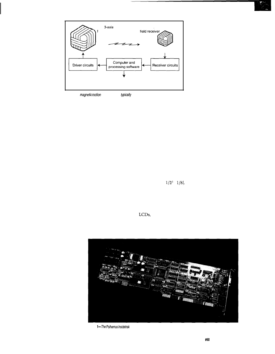
common center). A typical low-cost
tracker has a transmitter (the reference
set of antennas), a receiver (the tracked
set of antennas), and a PC-compatible
electronics board (see Figure 1). One of
the lowest cost PC-compatible track-
ers available today, the Polhemus
Insidetrak, is shown in Photo
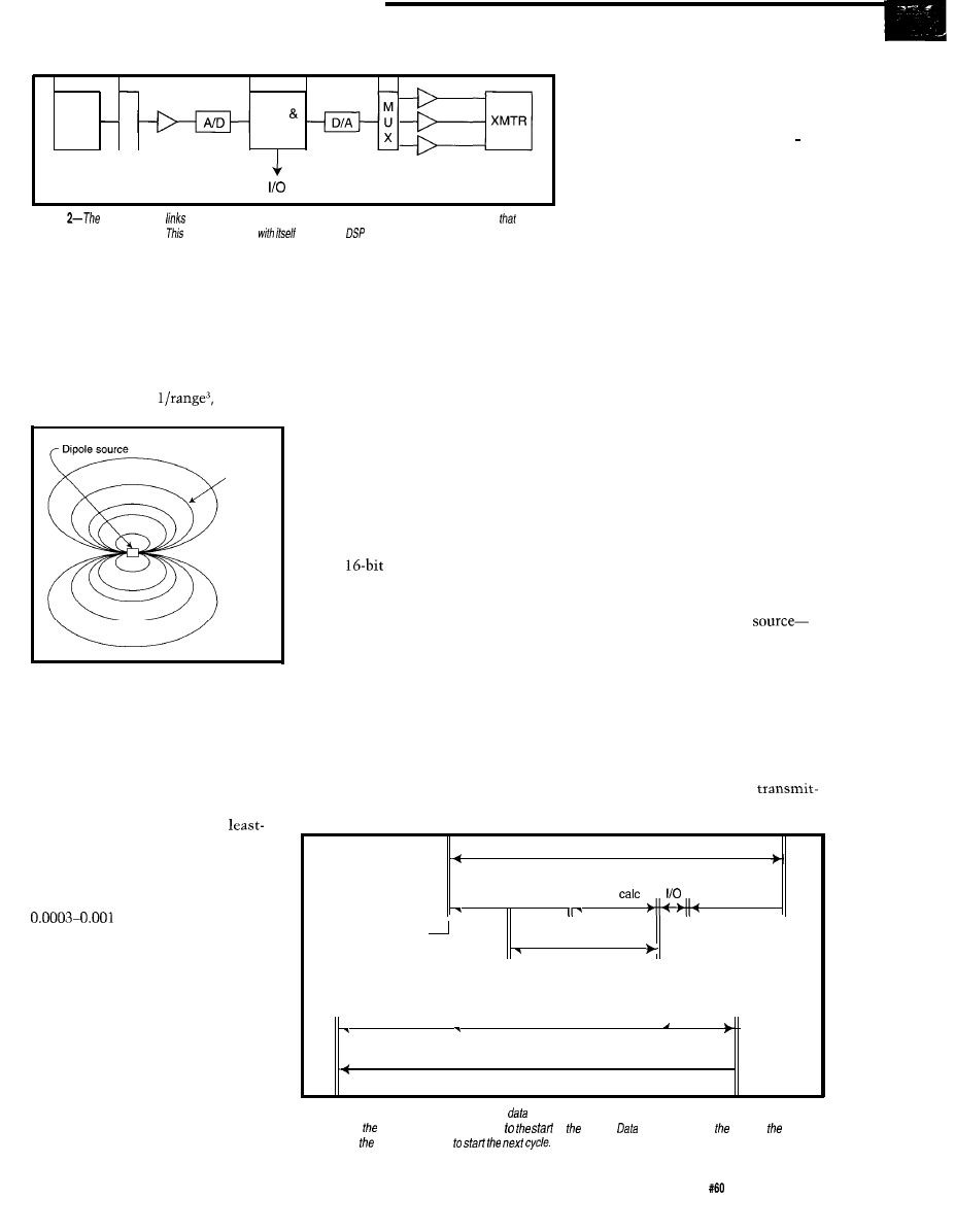
The tracker’s PC-compatible elec-
tronics can be separated into analog
and digital portions. Three receiver
antennas are connected to three analog
input channels as pictured in Figure 2.
These channels are composed of three
low-noise, high-gain amplifiers whose
outputs are multiplexed into a single
fast, high-resolution A/D converter.
The three transmitter antennas
are driven by three high-power analog
outputs. These outputs are digitally
generated via low-resolution DA con-
verters.
No doubt, you realize that other
configurations are possible: separate
A/D converters representing each
channel, a multiplexed D/A converter,
and so on. The tradeoffs between the
different configurations affect overall
price and performance of the tracker.
Analog inputs and outputs are
under control of a microprocessor. In
recent designs, a DSP has become
common since it better performs digi-
tal-filtering functions. The DSP is
responsible for generating the trans-
mitter signals, collecting the multi-
plexed input data, processing the raw
input data into P&O data, and interfac-
ing to the I/O bus.
These processes occur during a
typical tracker measurement cycle.
During the data-acquisition time, the
transmitter antennas are driven and
the induced receiver voltages are mea-
sured. This process takes most of the
measurement cycle.
Calculation of P&O from the
collected data occurs next and uses a
smaller part of the cycle. The remain-
ing time is dedicated to performing I/O
over the PC bus (or buses like
422 or IEEE-488 for external tracker
24
Issue
July
1995
Circuit Cellar INK
designs). Once a cycle
completes, a new mea-
surement cycle begins.
The equations defin-
ing the antenna couplings
are well known and are
solved to give the P&O of
the receiver with respect
to the transmitter. The
main fault with this type
of tracker is exhibited
when it is used near con-
ductive materials.
Figure
1-A
tracker system
includes a transmitter, receiver, and a
PC-compatible electronics
board.
materials receive and retransmit these
fields as well. These additional fields
are not accounted for and do not fit the
assumptions of the tracking algorithm.
Because trackers
generate AC magnetic
fields, nearby conductive
field transmitter
3-axis
Magnetic linkage
Position and orientation
measurements
The advantage, however, is that
magnetic trackers do not require an
unobstructed view between receiver
and transmitter like an infrared or
ultrasonic system. And, when designed
correctly, they are reasonably immune
to interference from other electronic
gear, but more on that later.
TRACKER SPECIFICATIONS
One of the problems in tracking
real-time movement is the interval of
time called latency. Latency is mea-
sured from the midpoint of the time
period during which data collection
occurs (i.e., the midpoint of the mo-
tion during this interval) to the start of
the output of a P&O solution.
You might wonder about the data
taken before and after the midpoint.
The crafty tracker designer, using
linear prediction, adjusts the collected
data from the ends of the data acquisi-
tion toward the middle. However, this
only covers tracker latency. When a
tracker is integrated into a VR system,
the overall [or system) latency needs to
be reckoned with (more on this later).
Other tracker specifications that
need definition are:
l
update rate
l
accuracy
l
resolution
l
repeatability
Update rate is the interval of time
between P&O solutions. If the mea-
surement cycle is 33.3 ms long and the
tracker computes a new P&O solution
Accuracy indicates how well the
computed P&O matches the actual
each measurement cycle, the update
position and orientation. Accuracy is
rate is 30 Hz.
affected by many of the overall sys-
tem-engineering design considerations
including the size of the receiver and
transmitter antennas, mechanical
assembly of the antennas, drive signal,
and signal-to-noise ratio (
SNR
), among
others. SNR itself is affected by a com-
bination of factors including tracker
design, its electromagnetic environ-
ment, and the range between transmit-
ter and receiver.
A typical contributor to environ-
mental noise is the display. Although
many are electrically quiet
TVs
and display monitors are CRTs which
generate magnetic fields during re-
fresh. The relatively low-frequency
vertical refresh can easily
overload the tracker’s
sensitive front end. The
higher-frequency hori-
zontal refresh has become
less of a problem recently
as these rates have in-
creased beyond the
tracker’s passband.
As noted earlier, the
other environmental
threat stems from conduc-
tive materials. Every ef-
fort should be made in
system design to use non-
conductive materials like
plastic, wood, and glass. If that is im-
possible, poor conductors such as cast
iron and some types of stainless steels
can often be tolerated with small ef-
fects. The worst materials to use are
good conductors like copper, alumi-
num, and brass.
The signal strength that combats
such noise drops off as the cube of the
transmitter-receiver separation since
the magnetic field must flood the 3D
space. In other words, if the range of
separation is doubled, the signal drops
to one-eighth of its earlier value (i.e.,
=
Obviously, SNR is always
an issue in trackers. You’ll note the
same problem occurs with resolution.
Resolution is the smallest change
a tracker can detect in position and
orientation. As with accuracy, both
system and environmental factors
affect resolution. Internally, the reso-
lution of the A/D converter and P&O
computation, the circuitry SNR, and a
Photo
board is one of the lowest cost PC-compatible trackers available
today.
Circuit Cellar INK
Issue
July 1995
25
_ M P r e - a m p
RCVR
U
-
x
DSP
Memory
Figure
motion tracker
three antenna coils carrying signals coupled from three transmit coils
are
being driven simultaneously.
communication
is
an idea/
application.
magnetically
noisy environment de-
grade the final resolution.
The final and ultimate limiter of
resolution is the separation between
the receiver and transmitter. A VR
tracker might have a working range of
l-5’. Because the strength of the mag-
netic field varies at
the signal
not normally specified, it obviously is
related to both accuracy and resolu-
tion. If the accuracy varies due to un-
corrected drifting of the circuitry,
repeatability suffers. Likewise, if the
resolution is so gross that you can
easily straddle the demarcation line
between two adjacent ADC readings,
repeatability again suffers.
Dipole
magnetic
field
Figure
4-The dipole field is symmetrical around any
axis drawn through ifs center.
drops rapidly with separation.
The maximum signal is designed
to occupy the full range of the A/D
converter. As the signal decreases, the
number of bits required to represent it
also decreases so that only the
significant bits are left taking readings.
Positional resolution is therefore
specified as a function of range. It can
be expected to be on the order of
inch per inch. Orienta-
tion resolution, being based on ratios
of measurements, is independent of
range (except that it’s still dependent
on data which is represented by a
smaller and smaller range of bits] and
is usually something like 0.1-0.5”.
Repeatability refers to the
tracker’s proficiency at providing the
same P&O output when the receiver is
placed in exactly the same position
and orientation with respect to the
transmitter over and over again. While
TRACKER INTERFACING
Now that we know how a tracker
works and what its key definitions are,
it’s time to get to what an application
buff might call the “good stuff.” A
low-cost tracker board is usually based
on the
ISA bus standard for
maximum utility (it should work on
an EISA bus also). Input commands,
tracker status, and data are 16 bits
long. A jumper block or switches for
setting a bus address are available.
Assuming you’ve read the tracker
manual, you have set the correct ad-
dress to a value different from any-
thing else on the bus.
data are transferred per P&O answer at
Being able to access tracker data
directly on an internal bus is a plus.
Considering that quite a few bytes of
least 30 times a second, a great deal of
real-time data must be handled. Many
trackers on the market today use a
serial bus such as RS-232, -422, or
485. However, these units not only
must run at a high baud rate, their
system software must navigate consid-
erable overhead. As you know, over-
head delays getting the data.
Typically, one would like that
data directly in the binary representa-
tion of the computer. This facility
usually is not the case with external
interfaces, adding a formatting or con-
version task to the software, and
thereby adding more delay.
So, with a PC, having the tracking
data available right on the ISA bus is a
marvelous feature. It makes the
tracker appear faster than it really is
compared to external trackers.
SYSTEM ALIGNMENT
Probably one of the hairiest parts
of setting up a motion tracker is get-
ting the transmitter and receiver coor-
dinate systems figured out and coordi-
nated with the video. Of course, every-
thing in a magnetic motion tracker is
referenced to its own signal
the transmitter.
ter alignment and receiver boresight.
This reference frame typically is
called the
space frame.
The coordinate
framework for the receiver is typically
called the body
frame
since it usually
is located on your body.
Two processes need to be under-
stood to get these frameworks to coop-
erate with your video world:
Tracker cycle
Next cycle
Data acquisition
P&O
setup
sync
Latency
Program
r
data request
Command or
Data
sync time
I I
Tracker response time
transfer
II
.
System latency or lag time
.
Figure
4-The tracker transmits and acquires
and then calculates position and orientation. Tracker latency
extends from motion acquisition midpoint
of output.
out continues at pace of host
computer as tracker prepares
Circuit Cellar INK
Issue
July 1995
27
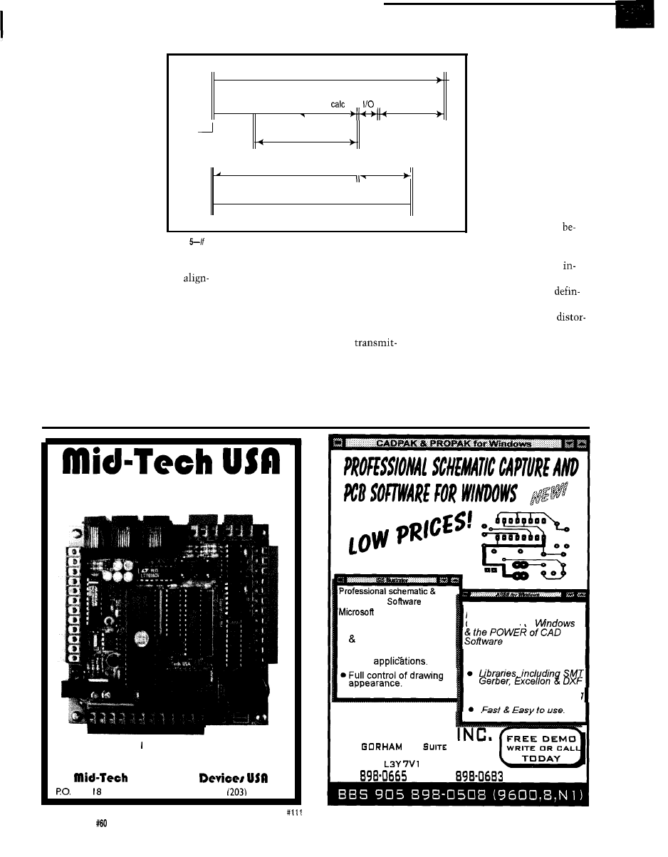
Alignment of the
transmitter can be done
mechanically, but it is
much harder than the
mathematical method
provided in the tracker.
Aligning the transmitter
is similar to setting up a
camera to pan in the
horizontal plane. If you
turn left and see nothing
but sky and turn right
and see nothing but
ground, you know the
the dipole field shown
Tracker cycle
in Figure 3. It is easy to
Next cycle
see that it is symmetri-
Data acquisition
P&O
setup
cal about any axis drawn
.
II
through its center. This
Sync
symmetry means there
Latency
are identical answers
Data
180” apart. Hence, the
Tracker response time
transfer
user must define which
hemisphere obtains the
System latency or lag time
right translational out-
put.
Determining this is
usually quite easy
camera is tilted.
Figure
you compare this figure to Figure 4,
if is obvious fhaf the continuous mode results in
cause you are walking
Similar processes
much greater efficiency.
either on the floor or on
are available in the
the ceiling, sitting
tracker to carry out transmitter
But, the body frame can be referenced
side the cockpit or outside the canopy.
ment through collecting data and
simply by orienting the receiver in a
And, the tracker has means for
making mathematical adjustments.
certain direction and executing a
ing the hemisphere in its manual.
Going through the whole process is
boresight command. This position
However, be cautious with
beyond this article’s scope, but your
becomes the (0, 0, 0) reference in the
tion and hemispheres. Sometimes
tracker user’s manual is a lot of help.
body frame. However, if the
distortion can create an answer that
Once alignment is done, the
ter has not first been aligned, don’t
throws the reading into the opposite
receiver(s) can be similarly adjusted,
expect a boresight to align it. The
hemisphere. Needless to say, it’s easy
but it is much easier. Remember the
boresight only helps with the receiver.
to detect, can be very disconcerting,
receiver navigates relative to the
With a magnetic motion tracker,
and should be accounted for in system
transmitter’s space-frame coordinates.
hemisphere is also important. Refer to
design.
Very high performance C-programmable
controllers and development software
The ec.52 803 -compatible 8 MIPS controller
Call
for fill-line hardware/software product catalog
Computing
Box 2
l
Stafford, CT 06075
l
voice/fax:
684-2442
PCB design
for
Windows 3.1
l
Automatic wire routing
dot placement.
l
Exports diagrams to
other
PROVIDES all the
Convenience of
. Advanced routing
l
Includes Gerber Viewing
R4 SYSTEMS
1100
ST.
1 1 B-332
NEWMARKET ONTARIO
C A N A D A
905
FAX 905
28
Issue
July 1995
Circuit Cellar INK
SYSTEM LATENCY
In Figure 4, you see a complete
application cycle, including system lag
from cycle initiation to receipt of data.
Of course, you can’t afford to wait
for data after kicking off a tracker
cycle, but it is important to determine
what the latency time period is. Once
you know the interval, you can go
about other tasks and come back for
the P&O answer when it is ready. By
doing this, little time is lost.
It is even more efficient to set the
tracker into continuous tracking op-
eration. By
up with it, you
only need to return when an interrupt
indicates output is available (Figure 5).
Hence, each P&O answer precedes
display computation. The display
frame updates while the tracker comes
around with the next cycle.
You can also reduce system la-
tency by using only the parameters
you need and obtaining them in the
most efficient format for you. You
might want binary data rather than
ASCII or your application may need
only orientation angles and not posi-
tion. Besides saving memory space,
such cuts save code run time, I/O
transfer time, and formatting.
TRACKER EFFICIENCY PERKS
Even with an efficient internal bus
like the ISA, the user can realize even
more efficiency by
l
requesting only the parameters
needed
. choosing a compact, directly usable
data format
l
integrating the system cycle with the
tracker cycle through proper sync
generation
l
metering out the system cycle in the
most logical and computationally
sensible sequence
q
In his
career, Dr. Herschel1
has served as chief scientist,
program manager, and project engi-
neer for companies such as Andrew
Government Systems, Rockwell
International, and Martin Marietta
Aerospace. As vice president of
engineering at Polhemus, Herschel1
oversees product design and develop-
ment.
In his 15 years at Polhemus, Mark
Schneider has led the design and
analysis for commercial products.
This year he received the Academy
Award for Technological Achievement
from the Academy of Motion Picture
Arts and Sciences, Mark serves as
Polhemus’s manager of newproduct
design. Mark may be reached at (802)
6553159, ext. 290.
Tom Jones
Polhemus, Inc.
P.O. Box 560
Colchester, VT 05446
(806) 655-3159, ext. 234
Fax: (802) 655-1439
404
Very Useful
405 Moderately Useful
406 Not Useful
Odds are that some time during the day you
will stop for a traffic signal, look at a message
display or listen to a recorded announcement
controlled by a Micromint
We’ve
shipped thousands of
to
Check out why they chose the
by
calling us for a data sheet and price list now.
MICROMINT, INC.
4 Park Street, Vernon, CT 06066
(203)
(203) 872-2204
in Europe: (44)
Canada: (514)
Australia:
lnauiries Welcome
Circuit Cellar INK
Issue
July 1995
29

James Goel
Digital Video Resizing
and Compression
essential in modern
video systems. Powerful workstations
combine graphics and scaled digital
video to create today’s hottest com-
puter animation. Everything from huge
video walls in trendy night clubs to
video-in-a-window teleconferencing on
a desktop PC requires digital-video
resizing. With the invention of modern
graphical user interfaces, people expect
to control how and where their video
data is displayed-they’re no longer
content watching fixed-sized video.
Distortion-free scaling is crucial in
applications like video production,
teleconferencing, navigation instru-
mentation, and medical imaging
because these applications demand
high-quality output. Modern systems
chain devices together to manipulate
digital video during production.
Throughout this process, quality video
scaling must be used to prevent
contamination of final video output.
Multiple resizable video windows
are the next evolutionary progression
for modern computers. In fact, the
upcoming release of Windows
contains integrated video playback
software for applications like video
conferencing, advanced
aided learning, and CD-ROM games.
Understanding high-quality
scaling requires a little background
information. First, I’ll cover antique
resizing algorithms which set the stage
for new scaling technology. However,
old or new, the basic concept of all
video scaling is determining how to
generate and position output target
pixels in relation to the input source
pixels.
But, before a digital nirvana of
cost-effective, high-quality integrated
video arrives, a number of
difficult problems must be
solved. The first is a lack of
storage and transmission band-
width. Video data is too massive
to be stored or transmitted
without compression, though
this situation has improved with
video compression standards like
By the way, the techniques
mentioned in the next section only
Figure 1 a--The
nearest-neighbor resizing
algorithm
is fast and
cheap but results in poor-quality output. this example, fhe
pixel in the source is dropped from the final image.
the Moving Pictures Experts Group
(MPEG-1 and H.261, and the Joint
Photographic Experts Group (Motion
JPEG). These standards are widely
accepted and use various algorithms to
achieve compression ratios of 100: 1
and beyond.
The second problem is a lack of
quality scaling. Efficient video com-
pression is just one link in a chain. It
must be coupled with effective
resizing to create an image worth
viewing. Until recently, systems relied
on the “cheap and nasty” nearest
neighbor
or the slightly better linear
interpolation
algorithms for video
scaling.
Unfortunately, these algorithms
produce video images suffering from
aliasing (visually evident as absent
image detail or extraneous artifacts).
Until now, resulting picture quality
has ranged from barely acceptable to
poor. Fortunately, new cost-effective,
high-quality scaling algorithms have
been developed.
30
Issue
July 1995
Circuit Cellar INK
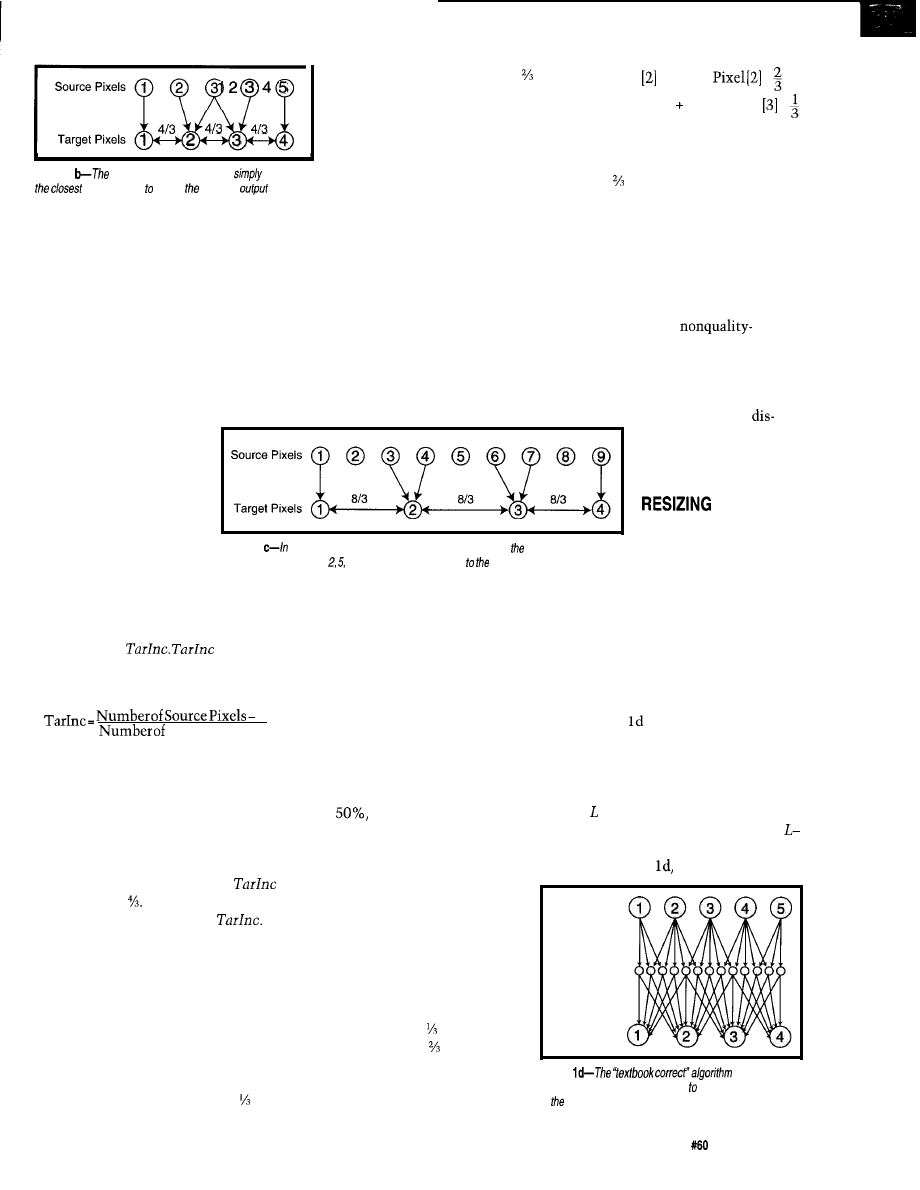
Source Pixels
Target Pixels
Figure 1
linear interpolation algorithm
averages
source pixels create required
pixels. At
most, each output pixel is generafed from a maximum of two
input pixels.
involve resizing of horizontally spaced
pixels. Vertical scaling is already
covered since all algorithms can
perform vertical resizing if entire video
lines are substituted in place of single
pixels.
NEAREST NEIGHBOR
The nearest-neighbor algorithm
could also be called
“keeping up with the
Joneses” because each
target pixel finds its closest
neighbor and copies it. This
cheap and simple algorithm
runs quickly, but produces
the right of source pixel 2 and
to the left of target pixel 3. Thus,
source pixel 2 maps to target
pixel 2 because it is nearest.
As you can see, after all
pixels are mapped, source pixel 3
does not contribute to the target
image. Remaining unmapped
source pixels are automatically
thrown out.
The problem with this algorithm
is that source pixels are removed if
they do not closely neighbor target
pixels. Entire lines and columns drop
from the original image. These visual
distortions are obviously unacceptable
for medical applications where doctors
require the highest image fidelity
possible for accurate diagnosis.
Target Pixel = Source
x
Source Pixel x
It
is
important to note that since target
pixel 2 is closer to source pixel 2, it is
made of more of source pixel 2 than
source pixel 3. All other target pixels
are calculated by determining their
position in relation to two surrounding
source pixels.
This technique produces poor
results for high-quality images with
sharply defined lines and barely
passable results for
sensitive images. Figure lc illustrates
this problem. Source pixels 2, 5, and 8
do not contribute anything to the
target pixels causing the same line and
column dropping
cussed earlier.
a
distorted output.
The technique begins
Figure 1
this case, linear interpolation has degenerafed info nearest-neighbor
algorithm. Source pixels and 8 make no contribution oufpuf target pixels.
with first determining the
closest neighbor. The space between
target pixels is calculated in relation to
the space between source pixels. Let’s
call this value
describes
the output grid spacing on which new
target pixels must be placed:
Schematics and line drawings are also
susceptible to the harsh aliasing effects
of the nearest-neighbor algorithm.
LINEAR INTERPOLATION
1
Target Pixels- 1
Linear interpolation improves on
the nearest-neighbor algorithm by
calculating the value of each target
pixel as the weighted average of the
two closest source pixels. This
technique prevents pixel and line
dropping for certain resize factors
above
but aliasing still remains a
problem.
resizing must be per-
formed for all resize
factors without informa-
tion loss through line or pixel drop-
ping. To achieve this, each source
pixel must contribute appropriately to
the output. Scaling video correctly
results in the highest quality images,
though it comes at increased complex-
ity and cost.
The subtraction of 1 in both the
numerator and denominator is re-
quired because the spaces between
pixels are important, not the pixels
themselves.
Figure la illustrates an example
where five source pixels are reduced to
four target pixels. In this figure,
turns out to be All target pixels are
separated by a space equal to
The exact position of each target pixel
in relation to the first source pixel is
now known.
The next step is to calculate the
value of each target pixel. In this
algorithm, source pixels are mapped
directly to the target pixels that are
spatially close. In our example, source
pixel 1 maps directly on top of target
pixel 1, and target pixel 2 moves to
In Figure lb, although the spatial
positioning of the target pixels is
the same as the nearest-neighbor
method of Figure la, the value for
each pixel is calculated differently.
The first source pixel maps directly
to the first target pixel, but the
second target pixel is calculated as a
weighted average between source
pixels 2 and 3.
Figure illustrates an example of
textbook-correct resizing using
multirate digital signal processing. The
multirate approach involves two steps.
If an image is being resized from
M to pixels, the first step generates a
set
of upsampled pixels by inserting
2 intermediate samples between each
pixel. In Figure five source pixels
Source Pixels
Target pixel 2 is to the right
of source pixel 2 and to the left of
source pixel 3. Thus, the following
equation calculates the value of
target pixel 2:
Target Pixels
Figure
ensures each
source pixel makes a contribution fhe output, regardless
of resize factor.
“TEXTBOOK
CORRECT” VIDEO
Correct video
Circuit Cellar INK
Issue
July 1995
3 1
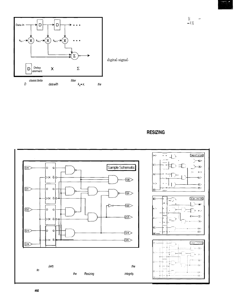
Data out
0
Multiplier
0
A d d e r
Figure 2-h a
impulse
response (FIR)
implementation, delay
elements proper/y align input
filter coefficients generafing
proper data out sum.
must be reduced to four target pixels.
Therefore, three intermediate samples
are inserted between each source pixel.
These upsampled pixels are generated
using an interpolator.
The second step generates target
pixels from the upsampled pixels using
a decimator. The classic pipelined
structure of a finite impulse response
(FIR) filter decimator is shown in
Figure 2. Basically, the decimator
multiplies upsampled
pixels by a set
number of coeffi-
cients called filter
taps
and sums the
products to produce a
single target pixel.
The coefficients are
calculated based on
processing theory to
produce target pixels
with a minimum of
aliasing. This system
of upsampling prior
to creating target
pixels minimizes
aliasing for any resize factor.
However, implementing this
algorithm presents two difficulties.
The first is caused by the directly
proportional relationship of the resize
factor to the number of upsampled
pixels.
For example, if a user wanted to
resize 1000 pixels down to 999, then
you’d start by generating the
upsampled pixels:
Figure 3-Source
image
is unchanged. The righf row shows three different methods of scaling
source image 45% of original size. Pixel dropping (fop) and bilinear interpolation (middle) lose precious
image data. The bottom image, reduced using Acuity
algorithm, maintains image
upsampledpixels = 1000 + 1000 1) x
(999
= 998,002
Since these upsampled pixels must be
generated in real time, either fast clock
cycles or large amounts of VLSI real
estate are needed to pipeline the
upsampling process.
The second difficulty lies in the
classic FIR filter structure shown in
Figure 2. New filter coefficients are
required for each resize factor to
ensure upsampled pixels are decimated
properly to produce unaliased target
pixels. Calculating FIR coefficients for
every resize factor is difficult and
expensive to implement in silicon.
These two problems make implemen-
tation of the multirate approach
impractical on a silicon microchip.
Fortunately, new algorithms have
made it possible to implement correct
video scaling on a single VLSI chip.
TECHNOLOGY
What’s needed for high-quality
resizing is separable FIR filters which
32
Issue
July 1995
Circuit Cellar INK
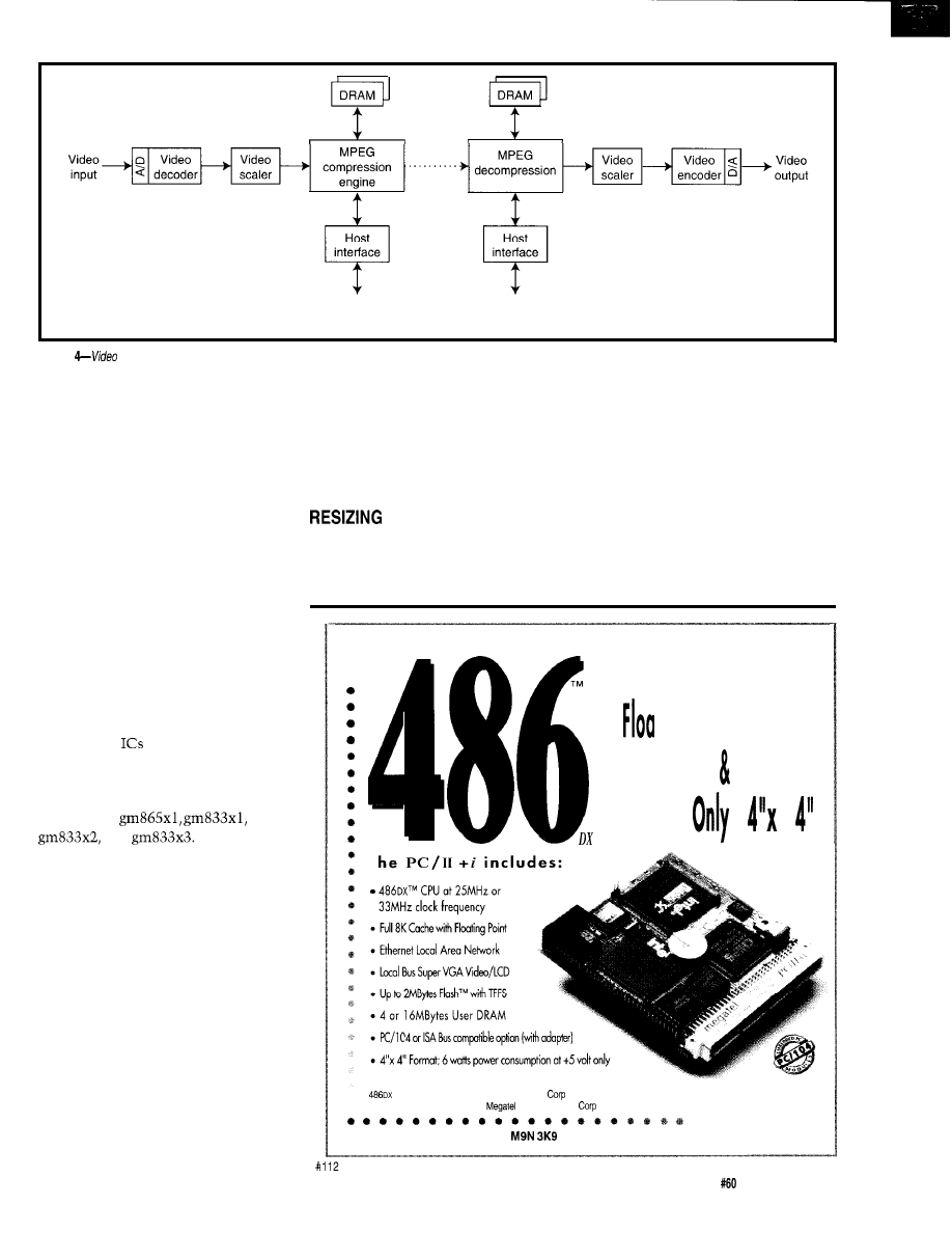
DRAM
System BUS
(PCI, VL-BUS, ISA)
System BUS
(PCI, VL-BUS, ISA)
Figure
scaling before and after compression is an effective way of improving transmission throughput.
provide arbitrary and independent
scaling in both vertical and horizontal
dimensions. Image fidelity is retained
by independently selecting the
optimum vertical and horizontal filters
so that image frequency content is
removed and aliasing is minimized.
The Acuity Resizing family, a
series of video/image resizing engines
from Genesis Microchip, implements
this technology. Depending on the
selected resize factor, the engines can
operate in reduction, bypass, or zoom
modes with FIR filters ranging in
complexity to 65 taps. The number of
filter taps is selected automatically
based on the resize factor.
As well, all required vertical and
horizontal FIR filter memory resides
on chip. The
can be cascaded to
resize extremely large images or to
implement high-speed systems.
The family currently includes four
devices: the
and
All chips
consist of vertical and horizontal
filters, an output FIFO, a parallel host
interface, and associated control. The
output FIFO buffers the different input
and output data rates while a parallel
host interface enables the user to load
source and target image parameters.
Control consists of pixel input hand-
shaking, field reset, and output FIFO
empty and half-full flags.
Figure 3 compares the quality of
the different resizing algorithms. As
you can see, pixel dropping and bilin-
ear algorithms (bilinear is linear inter-
polation in both vertical and horizon-
tal directions) distort the image with
horizontal and vertical aliasing. The
Genesis scaling algorithm maintains
the image quality at all resize factors.
Distortions caused by lower-cost
algorithms make them unacceptable
for even moderate-quality systems.
TO ENHANCE VIDEO
COMPRESSION
crystal-clear, overlapping video
windows on your computer desktop.
But, if you want to send these moving
pictures to a friend or keep more than
a few on your hard drive, image size is
still a problem.
One major stumbling block to
wider integration of digital video is a
lack of transmission and storage
With contemporary techniques, it
bandwidth. Full-motion video (running
is now possible to display multiple,
at 30 fps) requires transmission
. W O R L D ’ S S M A L L E S T
l
l
Embedded PC with
ting Point,
Ethernet Super
VGA
T
and Flash are registered trademarks of Intel
as are PC, AT of IBM, megatel of
Computer (1986)
( 4 1 6 ) 2 4 5 - 2 9 5 3
megatel”
125 Wendell
Ave.
l
Weston, Ont.
l
l
Fax: (416) 245-6505
Circuit Cellar INK
Issue
July 1995
33
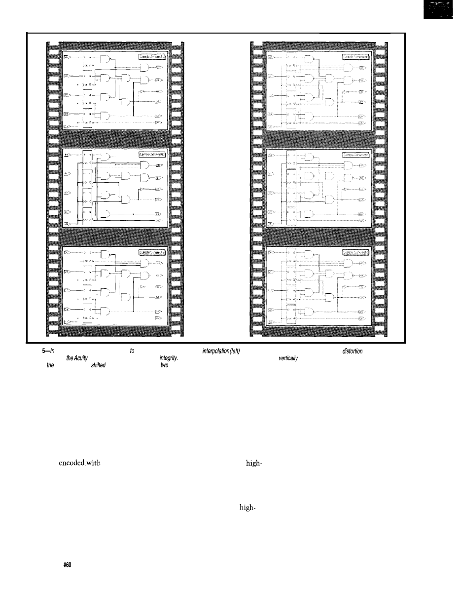
Frame 1
Frame 2
Frame 3
Figure
a
motion video sequence, reduced 47% of ifs original size, bilinear
demonstrates a high degree of temporal image
while the
technique used by
Resizing series maintains image
The source image for the middle row is shifted
and horizontally one pixel each way. The source
image for bottom row was
vertically and horizontally
pixels each way.
bandwidths a full magnitude larger
than those required for static images.
The MPEG video compression stan-
dard has reduced this barrier. MPEG-1
and MPEG-2 use motion compensa-
tion, discrete cosine transformation,
and entropy coding techniques to
achieve extremely high compression
rates. Many new Hollywood films are
now being
MPEG-1 and
stored on CD-ROM for playback by
computer and home-video playback
machines.
Figure 4 is a block diagram of an
MPEG compression system enhanced
by scaling. Analog video is digitized
and resized to reduce the amount of
data prior to compression. Next, the
data is crunched and saved to disk.
34
Issue July
1995
Circuit Cellar INK
To display previously stored
MPEG compressed video, the process
is reversed. A compressed video file is
read, decompressed, and resized to its
original size (or any other desired size)
by a resizer. After scaling, the video is
converted back to analog format and
displayed on a monitor.
An MPEG engine can perform
optimal compression only on
quality video received after video
scaling. If a lower-quality method is
used, the compressed file size in-
creases because the MPEG engine
works harder to encode the
frequency artifacts introduced by
aliasing. With inferior resizing tech-
niques, a slight shift in the input
source can completely change the
resulting resized image content. In a
motion video sequence, this can result
in image flickering or scintillation.
To simulate camera movement in
Figure 5, the source image was shifted
one pixel horizontally and vertically
prior to resizing. As you can see,
bilinear interpolation demonstrates a
high degree of temporal image distor-
tion while the techniques used by the
Acuity Resizing chips maintains image
integrity.
The ability to finely control the
image size in the video stream before
and after compression has many
applications. For example, if you have
a fixed satellite or cable transmission
bandwidth, you can transmit only a
certain number of compressed video
channels. Scaling video prior to
compression enables you to dynami-
cally fit more channels into the same
fixed bandwidth. Experiments have
yielded improvements in compression
throughput of up to
depending
on image content.
A video conferencing application
can benefit in a similar manner.
Normally, the entire data channel is
devoted to transmitting the faces and
voices of the two participants. Using
this video resizing technique adds an
extra communications channel so
participants can share documents or
other information while conversing.
AN EVOLUTIONARY STEP
Digital video is the next evolu-
tionary step in modern computer
operating systems. The combination of
video and computer graphics is creat-
ing entirely new classes of applications
in computer-based training, entertain-
ment, and communication.
This integration relies on two
complementary technologies: video
scaling and video compression. A new
generation of scaling and compression
algorithms gives users unprecedented
power to efficiently manipulate,
transmit, and store high-quality digital
video.
Integrated video and graphics are
here to stay-they deserve to look
their best!
q
is a senior video
DSP engineer at Genesis Microchip. A
former software and automation
engineer, he spends his days research-
ing compression improvements
through scaling technology. He spends
his nights dreaming of DSP. He may
be reached at (905)
Genesis Microchip Corp.
2111 Landings Dr.
Mountain View, CA 94043
(415) 428-4277
Fax: (415) 428-4288
407
Very Useful
408 Moderately Useful
409 Not Useful
HUGE BUFFER
FAST SAMPLING
SCOPE AND LOGIC ANALYZER
C LIBRARY W/SOURCE AVAILABLE
POWERFUL FRONT PANEL SOFTWARE
DSO Channels
2 Ch. up to 100
1 Ch. at
4K or 64K
Cross Trigger with LA
125 MHz Bandwidth
Logic Analyzer Channels
DSO-28204 (4K)
$2285 DSO-28264 (64K)
8 Ch. up to 100 MHz
4K or 64K
Cross Trigger with DSO
GAL
EPROM
EEPROM
FLASH
MICRO
Free software updates on BBS
Powerful menu driven software
up to 128 Channels
up to 400 MHz
up to 16K Samples/Channel
Variable Threshold Levels
8 External Clocks
16 Level Triggering
Pattern Generator Option
LA121 00 (100 MHz, 24 Ch)
LA32200 (200 MHz, 32 Ch)
LA32400 (400 MHz, 32 Ch)
$2750 LA64400 (400 MHz, 64 Ch)
Call (201) 808-8990
Link
369
Passaic
Ave, Suite 100, Fairfield, NJ 07004 fax: 808-8786
Circuit Cellar
INK
Issue
July 1995
3 5

Chuck
A
Motor
Speed Controller
challenge faced by all
mobile-robot builders. There are
After building several controllers,
prepackaged solutions, which come in
I bought a commercial
one of four forms: discrete compo-
nents, monolithic motor-driver chips,
speed controller (ESC) for R/C cars.
electronic speed controls for R/C cars,
and industrial controls. Unfortunately,
The controller had fully proportional
each solution costs an order of magni-
tude more than the previous one.
Many small companies are forced to
forward and reverse control for a motor
build their own from discrete compo-
nents or buy a motor control chip.
that could draw 10 A and it could be
controlled with just one bit.
However, it cost $89 on sale, and I
needed two. The combination of high
cost and high desirability had an
inevitable effect-1 had to figure out
how to build it for less.
This article describes my project.
After defining the problems in building
an ESC, I describe the program I wrote
for the PIC
which implements
the servo controller mechanism. The
conclusion looks at a couple of
bridges I built (one cheap and one less
so) that combine with the controller to
give a fully functional ESC.
THE CHALLENGES
The controller needed to be able to
reverse and have proportional speed
control over fractional-horsepower DC
motors. The control input was a pulse
whose width controls both the polarity
and duty cycle of the output.
I chose to use the convention
established for the control of R/C
servos and commercial electronic
speed controls which defines a pulse of
1500 us as the device’s neutral or
center position, a pulse of 2000 us as
the full positive extension or actua-
tion, and a pulse of 1000 us as the full
negative extension or actuation. The
pulse is repeated not more than once
every 5 ms and not less than once
every 20 ms for continuous actuation.
The servo controller in Figure 1
functionally consists of three parts: a
pulse-width measurer (i.e., a
capture unit), a PWM clock source that
can be modulated, and an expiration
timer to shut things off when an input
hasn’t been seen for a while.
Figure 1 represents this problem in
the form of black-box components.
The arrows in this picture represent
interfaces that can be defined for
maximum flexibility. The first arrow,
my challenge, is the “standard” servo
interface. Although I’ve never seen an
official standard, this is used by every
servo or ESC I’ve seen or read about.
The motor driver is simply a
switch providing current to the motor
based on what the servo controller
asks for. This driver circuit is known
as an H-bridge because it looks like an
controller
Motor driver
(H-Bridge)
Figure
block diagram of
typical
components, the arrows represent interfaces between the
components.
36
Issue
July 1995
Circuit Cellar INK
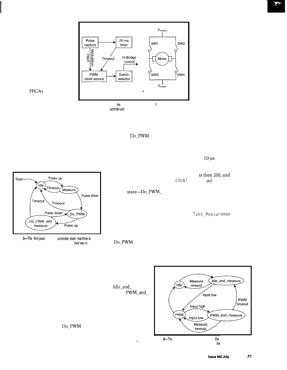
H when diagrammed. The
functional pieces are shown in
Figure 2.
DESIGNING THE SERVO
CONTROLLER
As you can see, the servo
controller can be implemented
in several ways. You might
build it out of individual
components or out of a single
FPGA. However, the design
tools for
are priced in
the stratosphere. PIC program-
mers, on the other hand, sell
for $200 and the development
software is free.
Controller side
Driver side
The trick is to design a program
that implements a servo controller. I
first defined the servo controller as a
state machine and then wrote an
algorithm to implement a state
machine. Next, I coded the algorithm
in PIC assembly code to determine
how fast I could get it to run. I then
defined the timing constants.
Figure
2-Adding detail to block diagram in Figure shows the functions
containedin the ESC
driver boxes.
The state machine treats it as a
timeout and returns to Idle.
Figure
at the
accurate, but doesn’t necessarily reflect the
'implement the application.
Once it enters the
state, the
state machine computes the duty cycle
of the output waveform and sends it to
the H-bridge.
This state exits under two condi-
tions: either 20 ms elapses without a
new pulse or the input pin goes
high indicating an incoming
pulse. When the input goes
high, the state machine enters
the fourth
and-Measure.
Here, it simultaneously
generates the PWM output for
the H-bridge and monitors the
input pulse width. If a valid
pulse width is received, it sets
the pulse width being generated
to the new value and returns to
the
state. An invalid
pulse times it out and returns it
to Idle.
state
machine that could implement
My first cut at designing a simple
the servo mechanism is shown in
Figure 3. The state machine starts in
an idle state. In this state, the proces-
sor monitors the status of the input
pin. When the pin goes high, it
switches to the Measure state.
realized a better state
However, after coding this,
machine could be used that
had four states. As Figure 4
indicates, the states are
now Idle,
Mea-
sure, PWM, and
Measure.
In the Measure state, one of two
things can happen:
I) the pin can go low, see the complete
pulse, and move to the
state
2) the pin can stay high for longer than
Although this looks
more complicated than the
first one, implementing it
is easier. This model lets
me factor out the measure-
ment operation, leaving me
with two main loops: Idle
the first algorithm for taking
measurements.
The
Take-Measure-
men t
algorithm simply
checks the state of the input
pin. If it is high, it incre-
ments the width counter. If
the input pin is low and the
width counter is less than or
equal to the minimum
number of clicks for a valid
pulse, it calculates the
requested PWM duty cycle
and direction and returns an
indication of a valid result.
The trick to this
algorithm is to call it at
regular intervals. If you know the
interval at which it is called, say every
10 us, then the conversion between
the variable
W i
d t h and the actual
width of the pulse is simply
W i
d t h
times the calling interval.
The constants can also be deter-
mined using a
interval. The
midpoint of 1500 us corresponds to a
width count of 150 (150 x 10 = 1500).
MAX-WIDTH
GLITCH_
is
9 (900
Once coded, calculate the theo-
retical minimum interval between
calls:
Loop:
call
got0 Loop
to
Knowing how many clock cycles
Take-Measurement usesandthe
overhead of calling it yields the exact
interval. Remember you can never
achieve this maximum because the
controller has to measure the input pin
Input high
PWM
timeout
Figure
modified state diagram for controller’s state
2 ms and appear as a bogus input.
and PWM. Listing 1 offers
machine is much more symmetric. It leads to software design used
Circuit Cellar INK
1 9 9 5
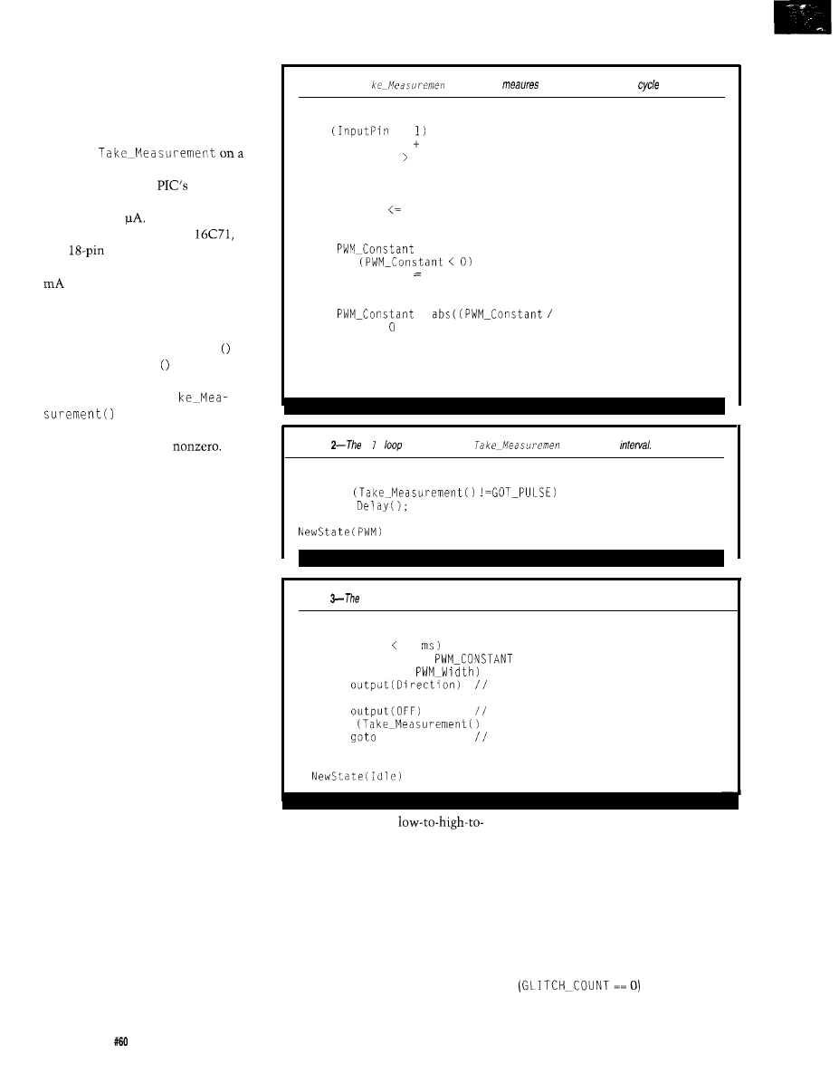
while simultaneously generating a
PWM waveform, which limits its
response time.
I chose to code the Idle and Idle_
and-Measure states as a single loop
thatcalls
regular interval. With two loops, I
could have used the
low-power
sleep mode, which cuts power con-
sumption to 2
However, this
requires a more expensive
the
first
device that can be awak-
ened. Since the PIC draws less than 5
when idling in a loop, the benefit
doesn’t justify the cost. The algorithm
for the I d 1 e loop is in Listing 2.
Take-Measurement0 processes
the input pin and calls De 1 ay This
ensures that Del ay
is called
regularly. The call is also needed
because later we call Ta
from within the PWM
loop, and the time it takes to process
the PWM waveform is
The main loop is the PWM loop,
which generates the variable-width
square wave as well as watching for
other incoming pulses. As you can see
in Listing 3, there is a lot more going
on in the PWM loop around the
Take-Measurement0 call,which
limits how often it’s called.
WRITING THE CODE
The only task left for the servo
controller is to convert the algorithms
into code. The code is written using
Microchip’s MPASM assembler (see
Microchip’s data sheet for a quick
overview of the PIC instruction set
and syntax). I’ve included most of the
interesting code here in the listings,
but you’ll want to download the
complete code from the Circuit Cellar
BBS to fill in the holes.
The most sophisticated part of the
software measures the width of the
incoming pulse. As mentioned, the
design requires the measurement
routine (see Listing 4) to be called on a
regular basis by the state loops.
This code executes in only 14
clock cycles. Execution time of this
routine determines the frequency of
generating the PWM signal.
DO-MEASURE has two jobs to
perform: it must accumulate time
when the input pin is high and track
38
Issue July
1995
Circuit Cellar INK
Listing l--The
Ta
t pseudocode
the incoming PWM duty
and direction.
Take-Measurement:
if
==
Width = Width 1
if (Width MAX-WIDTH) do
Timeout = TRUE
end
else do
if (Width GLITCH-COUNT)
return NO-PULSE
else do
= Width MIDPOINT
if
Direction REVERSE
else
Direction = FOWARD
=
MAX-CONSTANT) * MAX-WIDTH)
Width =
return GOT-PULSE
end
end
return NO-PULSE
Listing
Id e
pseudocode calls
t on a regular
Idle:
while
do
call
end
Listing
motor
PWM signal is generated complete/y in software.
PWM:
while (time 20
do
for count = 0 to
do
if (count <
turn on the H-bridge
else
turn off the H-bridge
if
== GOT-PULSE)
PWM
restart the loop
end
end
the input pin from a
low state, which indicates a control
pulse has been received. Once it
recognizes a control pulse, the width is
calculated and the necessary pins are
set to turn on the H-bridge. The code
must also recognize and screen out
invalid pulses. My first challenge was
checking for invalid pulses in the
fewest possible clock cycles.
Invalid pulses come in two flavors.
If they’re too short, a glitch occurs; if
too
long, there’s a timeout. I’ve used
countdown timers to detect both.
Thecounter GLITCH-COUNT
detects “too short” pulses. The
counter initializes to the minimum
count value needed to recognize a
valid pulse. Then, while the input pin
is high, this counter decrements until
it reaches zero, where it is no longer
decremented. The Boolean condition
istruewhenthe
pulse is longer than the initial value of
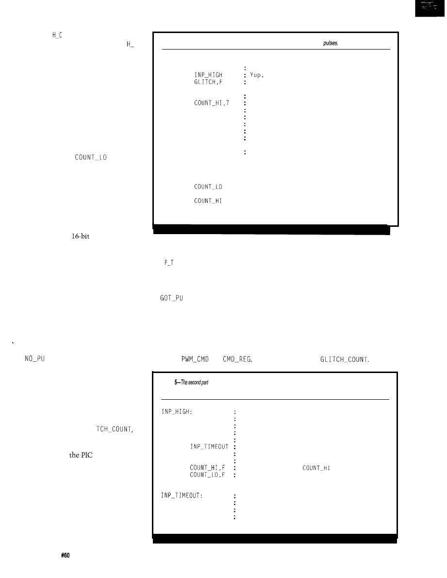
G L I TC
0 U NT, and false if the pulse
is shorter (see Listing 4). If G L I TC
COUNT isnonzero, NO-PULSE is
executed.
Timeout, the second invalid pulse,
occurs when the input pin remains
pulled high. Given the nature of the
circuit, this pulse occurs when the
circuit input is left disconnected. It
can also occur if the controller stops
operating correctly. In either case, the
controller should turn off the outputs
since timeout is not valid. To detect a
timeout, I use the width counter
implemented in
and
COUNT-HI.
If you think that by clearing the
counter to zero and counting up while
the pin is high gives the width of the
input pulse, you’re correct. As a 16-bit
.
counter, it could measure pulses much
wider than the ones we are interested
in. However, to detect overflows, we’d
be forced to do
subtraction of
some maximum legal value and then
see if a borrow was generated-a
solution far too time consuming.
Instead, I preload the counter with
the maximum legal value and decre-
ment it. If the pulse is too wide, the
counter underflows. Timeout simply
checks to see if bit 7 (sign bit) of the
counter is true (counter has gone
negative). Thus, with a glitch or
timeout, the code reloads the counters
and looks for the next valid pulse.
Note that I don’t just branch to
LSE when I detect a timeout
since that would make that path
through the code take one clock less
than the code that detects a glitch. In
all cases, the time it takes to process a
measurement must remain the same.
When the input is in a true state,
the width count accumulates (Listing
5) by decrementing GLI
COUNT-HI, and COUNT-LO
as
needed.
The only tricky bit is the down
counter. Since
does not set the
carry flag when a decrement under-
flows a register, the loop must check
the low byte for zero. At zero, the next
decrement underflows and affects the
high byte. A nice property of this
technique is that the 16-bit decrement
operation only takes four clock cycles.
As you can see from the code,
once the down counter has under-
Listing
4-The first part of fhe pulse measurement code screens out
invalid
DO-MEASURE:
BTFSC
SERVO-IN
Check for high
GOT0
count it.
MOVF
Check Glitch counter
BTFSS ZERO-BIT
; != 0 means Glitch.
GOT0
NO-PULSE
This was a glitch
BTFSS
Check for overflow
GOT0
GOT-PULSE
Process a good count
MOVLW
GLITCH-COUNT
Alternate NO-PULSE entry
MOVWF GLITCH
Store it in GLITCH
MOVWF COUNT-LO
Just a glitch,
MOVLW 1
Load count with constant
MOVWF COUNT-HI
RETLW 0
And return
NO-PULSE:
MOVLW GLITCH-COUNT
MOVWF GLITCH
MOVWF
MOVLW 1
MOVWF
NOP
RETLW 0
flowed (bit 7 is set), the code stops
accumulating counts and branches to
I N I M E 0 UT. This prevents a
rollover of the down counter should
the high pulse remain for a long time.
A valid input pulse is taken care of
by
LS E (Listing 6). This routine
converts the counted width of the
pulse into the parameters needed for
the H-bridge. The challenge here is to
Since there is a large interval
between valid pulses, this code takes
more clocks. The code shouldn’t take
too long, however, as the motor may
be on when it is called and this “on
time” is added to the current pulse.
This code also controls the
minimum time between legal pulses
that the controller can correctly
respond to. Although the design
have the pulse width (depending on its
specifies a minimum of 5 ms, the code
width) change what the controller is
implements it in under 1 ms. Finally,
doing by setting the value of command
the code specifies the time constants
variables
and
startingwith
Listing
of the pulse measurement code accumulates a width count when the input
pin
is true.
3 clocks have executed when we enter
MOVF
GLITCH,F
Check Glitch
BTFSS ZERO-BIT
Is it already O?
DECF GLITCH
No, then decrement it
BTFSC COUNT-HI.7
Not a timeout already
GOT0
Its a timeout
MOVF
COUNT_LO,F
Test COUNT-LO for zero
BTFSC ZERO-BIT
If its zero, this is it
DECF
Subtract one from
DECF
Subtract one from the count
RETLW 0
NOP
NOP
NOP
RETLW 0
9 clocks have executed when we enter
Filler to get 14 clocks
Filler to get 14 clocks
Filler to get 14 clocks
4 0
Issue
July 1995
Circuit Cellar INK
Listing
third
part of the pulse measurement code computes the portions of the H-bridge to turn on
and the PWM constant.
GOT-PULSE:
MOVLW
This is the midpoint.
SUBWF
BTFSS
CARRY-BIT
Carry is set (no borrow)
GOT0
DEAL-WITH-MINUS
Figure out what to do now.
POSITIVE-RESULT:
MOVLW
REVERSE_CMD It's probably reverse
MOVWF
Store it in command register
MOVLW
Dead band is
SUBWF
Subtract
from count
BTFSS
CARRY-BIT
If no borrow, continue
GOT0
DO-BRAKE
In the dead zone do braking.
MOVLW
0'100'
Check if its in the range
SUBWF
Subtract 99
range)
BTFSC
CARRY-BIT
Check if its Less than MAX
GOT0
Was >= 100
MOVF
Get count value.
FALL THROUGH TO DONE-PULSE >>
If the midpoint of the count is
represented by an
number (i.e.,
1500 us and a function is called every
128). Meeting this requirement
nearest 5
Given these numbers, we
calculate
GLITCH_COUNTtobethe
midpoint less the minimum pulse or
172 calls (300 calls 128 calls).
After the first calculation (width
midpoint), the result is a number
between -128 and
From this
number, we can get the direction to set
the H-bridge. If the number is negative
(a wide pulse), the direction is forward.
If the count is positive [a narrow
pulse), the direction is backward. The
only tricky bit here is that the count in
on the exact minimum pulse. When
this occurs, subtracting 128 from
carry)
instead of the desired
Listing 7, known as
D EA
I
M I N S,
handles negative values. This
code sets the direction of the H-bridge
forward and takes the absolute value of
the counter, making it a positive
25 clocks or 5 us, then at the
ensures the most dynamic range in the
value. However, this code also checks
point,
DO-MEASURE
has been called
system-it is able to count 128 counts
for the special case of
Once the
300 times (300 x 5 us = 1500
before or after the midpoint. Thus, our
count value is normalized, execution
Also, since the midpoint
measurement checks pulses from 1500
resumesasthe
POSITIVE_RESULTof
sponds to the “middle” value, it can be
640 us through 1500 640 us to the
GOT-PULSE.
your
Big-Company ma
department come
up
more
than
the
department can
cope with!
Are you a small company that can’t afford a full-time
engineering staff for once-in-a-while designs?
n
Steve Garcia and the Ciarcia Design Works staff may have
the solution. We have a team of accomplished programmers
and engineers ready to design products or solve tricky
engineering problems.
n
Whether you need an on-line solution for a unique problem,
a product for a startup venture, or just experienced
Insulting, the Ciarcia Design Works is ready to work with
Just fax me your problem and we’ll be in touch.
8 0 5 1
6 8 0 9
8 6
9 6
Low
Cost!! PC based cross development packages which
include EVERYTHING you need to develop C and assembly
language software for your choice of CPU.
MICRO-C compiler, optimizer, and related utilities.
A
Cross Assembler and related utilities.
Hand coded (efficient ASM) standard library (source included).
Resident monitor/debugger ( source included)*
Includes Integrated Development Environment and command
line tools
editor, telecomm and many other utilities).
*
and
kits do not include monitor/debugger.
A
Each Kit: $99.95 US + s&h (please specify CPU)
Super
DK (supports all 8
$300.00 US
Call or write for
free catalogue development tools.
FREE Demos
available on BBS (or send
diskette)
We accept
Development Systems
Ont.
CANADA
256-5821 BBS: 256-6289
Circuit Cellar INK
Issue
July 1995
41
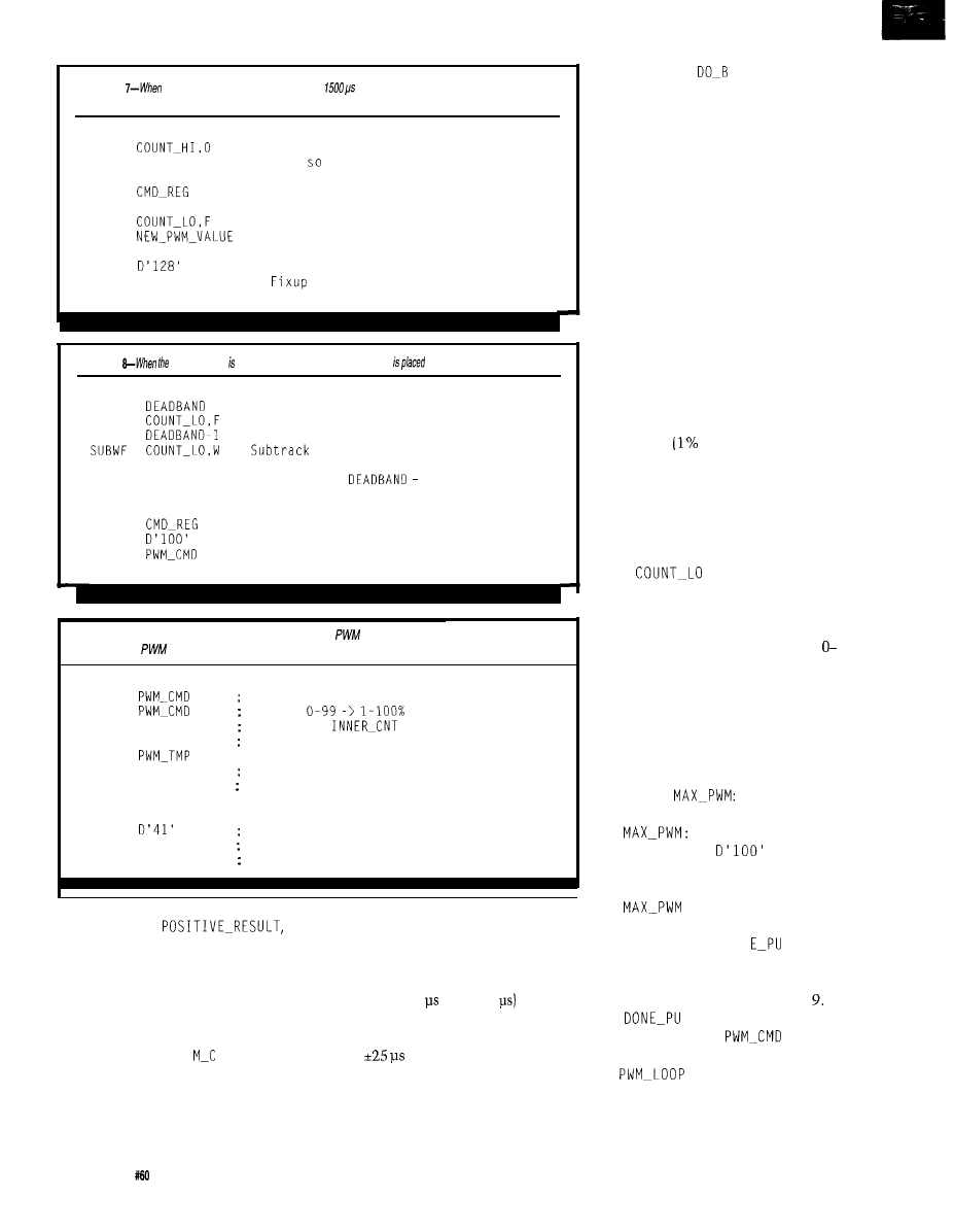
Listing
the input pulse is more than
wide, this code fakes the absolute value of the delta.
If also checks the special case of the absolute minimum pulse width.
DEAL-WITH-MINUS:
BTFSC
GOT0 ADJUST-RESULT
MOVLW FORWARD_CMD
MOVWF
COMF COUNT_LO,F
INCF
GOT0
ADJUST-RESULT:
MOVLW
MOVWF COUNT-LO
GOT0
POSITIVE-RESULT
Is bit 0 a one?
Yes,
adjust
It's wider than the midpoint
So this is the command.
Convert to a positive value
negate COUNT-LO
Now go compute PWM constant.
256 128 = 128
the low byte
Now treat it normally.
Listing
pulse width within the deadband, the H-bridge
in a braking mode.
DO-BRAKE:
MOVLW
ADDWF
MOVLW
BTFSC
ZERO-BIT
GOT0
ON-THE-EDGE
MOVLW
BRAKE_CMD
ON-THE-EDGE:
MOVWF
MOVLW
MOVWF
GOT0
DONE-PULSE
Restore Count Value
Add it back to Count
Check for boundary condition
COUNT LO
Check to see if it's zero
It's exactly
1
This is the brake Command
Store it
Very large PWM Constant
So we get 100% braking action
Return
Listing 9-The loop state must be initialized with a new
constant and H-bridge mode before
reentering the
loop.
DONE-PULSE:
MOVWF
This is the new PWM Constant
INCF
Adjust
MOVLW 1
Put 1 into
MOVWF INNER_CNT
Exit inner loop on this iteration
MOVWF
MOVWF COUNT-HI
Reset counter
MOVLW GLITCH-COUNT for next time
MOVWF COUNT-LO
MOVWF GLITCH
MOVLW
Outer Loop count + 1
MOVWF OUTER_CNT
RETLW 1
Return true (for idle)
Startingat
the next step is to determine the dead
band where the motor controller
brakes the motors rather than causing
them to move forward or backward. I
previously decided to have a propor-
tional zone 100 counts wide as this
makes the value in P W
M D a percent-
age of the duty cycle.
I also wanted a full-power zone in
which the controller does not do any
PWM at all but simply switches the
bridge fully on. I chose a dead band of
5,
which gives a total dead band of 10,
since it’s taken out of both the positive
and negative values. A dead band
width of 10 or 50
(10 x 5
is
easily attainable. Even with a fairly
inaccurate driving circuit, this gives
you a
margin of error.
In Listing 6, the width of the dead
band is subtracted from COUNT_LO. If
it goes negative (an indication that the
pulse width is in the dead band), the
code branches to
RAKE, the
routine included in Listing 8.
In testing this routine, I discov-
ered the system alternately brakes and
applies a 1% duty-cycle square wave
when the input signal is near the point
that going forward or backward begins
and braking engages. Although this
low-speed oscillation isn’t particularly
harmful, it is annoying.
To correct it, I added a test in
DO-BRAKE for reading a pulse width on
one or the other edge of the dead band.
When this tests true, I change com-
mand to off or zero.
By turning the bridge off, the
motor simply coasts. Because of this
modification, the output goes between
1% PWM and coast when the input
alternately picks up the minimum
power level
PWM) and brake.
When the input is on the other edge,
approaching the edge of the dead band,
the output varies between brake and
coast. Dealing with the boundary
condition in this way provides a more
stable system overall.
If
is greater than the
dead-band value, I continue ahead in
the POSITIVE_RESULT code.Since
I’ve subtracted the dead-band value,
the value in COUNT-LO, which was
128, is now O-123. However, any value
greater than 100 is “full on” as far as
the code is concerned.
The final step limits the output to
100 by comparing the value in
COUNT-LO to 100. If it is greater than
100, the carry bit is set and the code
branches to
MOVLW
GOT0
DONE-PULSE
simply sets the value to
100 (its maximum legal value) and
reenters execution at DON
LSE,
where all paths through the code
terminate. DONE-PULSE finalizes all of
the setup and is shown in Listing
LSE stores the computed
PWM constant into
and
manipulates the control variables of
the
code (see Listing 10).
This latter step is required because a
valid pulse can be received in the Idle
and PWM loops.
42
Issue July
1995
Circuit Cellar INK
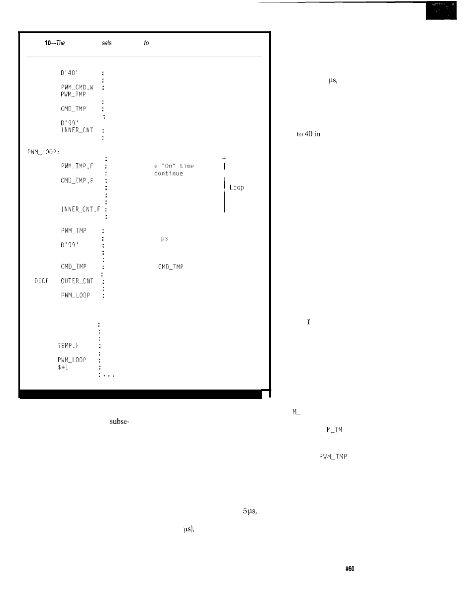
Listing
outer PWM loop
the loop count 40, which causes the if to run for20 ms. The inner
loop sends commands to the H-bridge.
PWM:
MOVLW
MOVWF
MOVF
MOVWF
MOVF
MOVWF
MOVWF
MOVLW
MOVWF
GOT0
Constant for 20 ms
OUTER_CNT
Outer Count
Set up the inner loop counters
CMD_REG,W
Get H-Bridge Command
Put it in our temporary holder
'BRIDGE-OUT Turn on the motors
PWMMLOOP
Line up command
CALL
DO-MEASURE
DECF
BTFSC
ZERO-BIT
SWAPF
MOVF
CMD_TMP,W
MOVWF BRIDGE-OUT
MOVF
PWM_CMD,W
DECFSZ
GOT0
PWMMLOOP
Do a "measurement"
Decrement the "On"
If not zero
Turn off the low side
Inner
Get the Command Register
Send it To the H-Bridge
Sort of a NOP
Decrement inner loop count
Continue Looping
+
MOVWF
CALL
MOVLW
MOVWF
MOVF
MOVWF
MOVWF
BTFSS
GOT0
Restore command (loaded in inner loop)
DO-MEASURE This is on a 5 boundary
Reset inner loop count
INNER_CNT
Like so
CMD_REG,W
Put command into W
Reinitialized
BRIDGE-OUT Send it to the motors
ZERO-BIT
; Unrolled Idle loop
CLRF
CALL
MOVWF
MOVF
BTFSS
GOT0
GOT0
NOP
GOT0
BRIDGE-OUT Turn off the motors
DO-MEASURE
TEMP
Store result in TMP
Waste time, set Z bit
ZERO-BIT
If zero no new value
If got a new value, then start
else Waste time
IDLE
; Go back to measuring
If the code is in the Idle loop, this
step is unnecessary since the
quent jump into the PWM code sets
these variables. However, in the PWM
loop, the code resets the variables so
the PWM loop code believes that this
is the first time through the loop.
The rest of the code is relatively
straightforward and consists of three
major chunks: PWM outer loop, PWM
inner loop, and idle loop. The next
chunk of code 1’11 describe is Listing
10's
PWM outer loop.
This idea behind the code is
simple: turn on the H-bridge, run the
loop 100 times, count down the PWM
constant, and when it gets to zero,
turn off the H-bridge. If the PWM
constant is
1,
the H-bridge is on for
1%
of the time spent in the inner loop. If
the constant is 2, the power is on 2%
of the time. This continues until you
reach 100, at which point the power to
the H-bridge is on 100% of the time.
Running the loop 100 times
determines the period of the output
waveform. Since the least amount of
time I can execute the loop is the
period of the resulting waveform is 500
us (100 x 5
which is a frequency of
2000 Hz. To modify the code for only
50 speed steps, use 250 us or 4000 Hz.
The PWM inner loop is distinct
from the outer loop. The outer PWM
loop times out the controller after 20
ms elapses with no new input arriving.
As demonstrated, the inner loop
executes in 500
so 40 iterations of
the inner loop takes 20 ms. When the
outer count is decremented to 0, 20 ms
has passed. The controller should
switch the output off. However, if a
valid pulse is received, the counter
resets
DONE-PULSE, which
causes it to run another 20 ms.
My pulse measurer design requires
that DO-MEASURE be called as often as
possible and always at the same
interval. In an interrupt-driven system,
a timer would go off every few milli-
seconds and call DO-MEASURE. But on
this PIC, I don’t have that luxury.
Because of this limitation, the critical
issue in the PWM loop is to call the
DO-MEASURE routine on a regular
schedule. This function goes to
extraordinary lengths to maintain
symmetry in both the inner and outer
loops using a technique called limited
loop unrolling.
The inner loop executes 100
times. However, by executing it 99
times and then recoding the same
contents of the loop after the loop
finishes, can use the clock cycles that
the inner loop normally uses to
compute whether or not the outer loop
is done. Notice in the listing that the
instructions at the bottom of the outer
loop are identical to the ones in the
inner loop, except that they now
compute something for the outer loop
instead.
The extra clock used by the GOT0
P W L 0 0 P instruction in the inner
loop is used in the outer loop to reset
the value in P W
P. Next, the inner
loop calls DO-MEASURE, so the outer
loop does as well. The inner loop then
decrements
to see
if the
output should be switched off.
The outer loop uses these cycles
to reset the inner loop count and to
send the command to the H-bridge.
The inner loop sets the H-bridge
outputs (as does the outer loop), then
decrements its counter. If the counter
is not yet zero, it circles back through
its loop. In the meantime, the unrolled
version in the outer loop decrements
Circuit Cellar
INK
Issue
July 1995
43
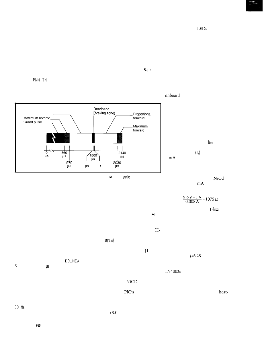
the outer loop’s counter and restarts
the inner loop if that isn’t zero. In this
way, DO-MEASURE is called every 5 us.
When
P crosses zero, I
swap the halves of the command byte.
The only other interesting bit in
The next time it is sent to the bridge,
the inner loop is how it turns off the
motor. Remember that after the PWM
the low-side driver has been turned off.
constant reaches zero we need to turn
off the motor. Since the bridge takes
four bits of output and Port A on the
PIC is a 4-bit output port, an alternate
command is stored in the upper four
bits of the command register.
The one extra instruction avail-
able from not branching back into the
Figure 5 illustrates the response of
PWM loop turns off the outputs to the
the system to different-width input
bridge. Next, I call DO-MEASURE right
on schedule and check to see if a new
pulses given the program and the
pulse has arrived. If it has, I reenter the
PWM code. If it hasn’t, the code
constants chosen.
branches to idle after ensuring that the
number of clocks that have passed is
sufficient so that when I d 1 e calls
DO-MEASURE, it is on another
interval boundary.
Proprotional reverse
1470
1530
Figure
5-A graphic illustration c/ear/y shows the response of the controller different
widths
I leave the high-side driver energized
because in FET designs it may be
driven by a charge pump. Turning it
off and on limits the efficiency of that
circuit.
There is, however, one final bit of
magic in this code which comes into
play when the PWM loop finally exits.
This final flourish takes care of the
valid pulse which starts coming in
when the PWM loop is running, but
finishes after it exits. As you may have
guessed, between the end of the PWM
loop and reentering the idle loop, the
code must continue to call
U R E every 5 or risk getting bogus
measurements.
Fortunately, there is a lot of extra
time in the idle loop since all that is
happening is that a potential incoming
pulse is being measured. As the
bottom of Listing 10 demonstrates, all
I need to do is ensure that
A S U R E is called on schedule and
that we reenter Idle as planned.
44
Issue
July 1995
Circuit Cellar INK
DESIGNING HARDWARE FOR ESC
By doing the servo code in soft-
ware, the hardware for the ESC is
greatly simplified. There are two
modules to the basic circuit: the servo
controller and the motor driver or
bridge. The servo controller drives one
half of a quad optoisolator (see Figure
6). The other half is connected to an
bridge and is implemented with
bipolar
or MOSFET transistors.
Notice that the servo module is
controlled from the input into the
servo connector. This connector has
three pins (V,,, signal, and Gnd) and
should nominally have 5 V on the
power pin. The PIC is capable of using
4.5-5.5 V. The standard R/C receiver
battery pack of four
cells
produces 4.8 V, which is acceptable.
Because of the
flexibility,
there is no regulator in the circuit. The
square-wave pulse input to the servo
connector falls within acceptable TTL
levels (i.e.,
V is a logic high). The
output pins of port A, RAO-RA3,
connect to the LED anodes in the
optoisolator. The
then connect
to 470-R current-limiting resistors.
Figure 7 shows the first H-bridge
implementation. In the schematic,
Ula-UId represent the other half of
the optoisolator from the servo module
circuit. By using an optoisolator, the
electrical noise generated on the
motor’s power-supply lines is kept out
of the circuit’s digital side. This
greatly increases the reliability of the
overall system, and, if you power the
ESC from the same supply as your
computer, it protects the
computer from interference as well.
The circuit uses the transistors as
switches, thereby driving them to
their saturation point. For this, the
base current should be at least I/h,,
amps. This prototype uses TIP120
(NPN) and TIP125 (PNP) transistors,
which are power Darlington transis-
tors with an minimum
of 1000. For
an 8-A current through the transistor,
the base current needs to be about
8
Use this figure and your motor
battery voltage to choose the resistor
value you need.
For example, if you have a 9.6-V
motor power source (eight
cells]
and wish to get 8
through the
resistor, you’d calculate:
In my prototype I used a
resistor
pack.
Four diodes, Dl-D4, are reverse
biased across the collector-emitter
leads of the transistor to snub the
reverse-current spikes occurring when
an inductive load is switched off. The
diodes can be any reasonable rectifier
you have handy as long as they have
fast recovery
us-our minimum
pulse width) and can handle a surge of
4-6 times the motor current. I’ve used
with good success.
This circuit generally runs 3-5-A
motors without needing a heatsink.
However, if you draw the maximum
current periodically (8 A), put
sinks on the transistors. Note that
because this is a common-collector
circuit, the motor voltage is present on
the tabs of the transistor bodies. So,
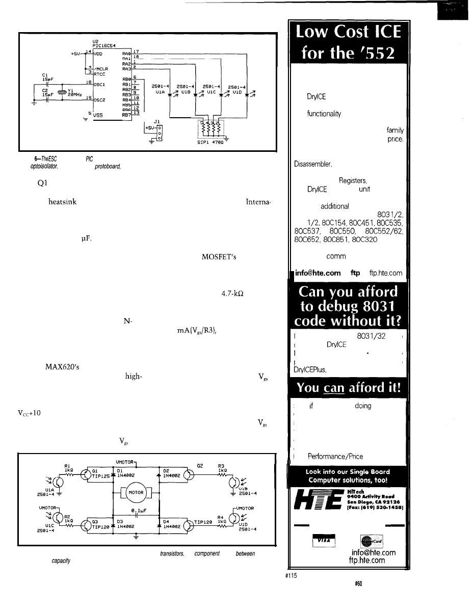
Figure
core uses a
processor. The interface between it and the electrically noisy H-bridge is a
quad
When built on a
ifs cost is about $9 including sockets.
while and Q3 can go on the same
heatsink, you must not put them on
the same
as Q2 or Q4.
Finally, the capacitor across the
just 5 V), this circuit uses motor
supplies of 5-30 V. I used Philips
BUKV455 MOSFETs, but the
tional Rectifier IRLZ44 is easier to
motor power leads filters noise
generated by the motor’s brushes and
should be about 0.1
The second implementation of an
H-bridge is in Figure 8. In this circuit,
N-channel, enhancement-mode power
MOSFETs are used as switches. Given
their geometry, MOSFETs handle
higher currents than bipolar transis-
tors. However, this feature is mitigated
by the somewhat more complex drive
requirements. Fortunately, using
channels as high-side switches got a
whole lot easier when Maxim intro-
duced the MAX620 Quad High-Side
Driver.
The
outputs are
connected to the gates of the two
side switches. The chip itself contains
an integral charge pump that produces
a voltage on the output pins that is
V, sufficient power to turn on
nearly any MOSFET.
By using logic-level MOSFETs
(full enhancement mode with a
of
come by and has a continuous-current
rating of 35 A!
Selecting the resistors for this
circuit is driven by the gates of the
MOSFETs. The
gate looks
like a capacitor, so R3 and R4 have to
be just small enough to drain off the
gate charge when the optoisolator
turns off. I found that
resistors
worked quite well for a wide set of
input voltages. At 5 V (worst case), the
current through R3 when Ulc is off is
about 1
which is well
able to turn off the MOSFET in the
minimum 6.5 us.
If you don’t use logic-level
MOSFETs, you have two choices:
increase the motor voltage so the
appearing on the low-side switches is
10 V or more (e.g., a 12-V motor
supply) or use the two unused drivers
in the MAX620 to drive the low-side
switches. Most MOSFETs have a
max of 20 V, so if you use this second
option, the motor voltage must be less
T I P 1 2 5
C 3
a 4
Figure 7-An
inexpensive H-bridge can be made using bipolar
The
cost is
$5 and
$10. Ifs current
is around 5 A.
Pods available for other
805 1 Family Processors:
The
Plus is a modular emulator
designed to get maximum flexibility
and
for your hard earned
dollar.
The common base unit
supports numerous
805 1
processor pods that are low in
Features
include:
Execute to
breakpoint, Line-by-Line Assembler,
SFR access, Fill, Set and
Dump Internal or External RAM and
Code, Dump
and more.
The
Plus base
IS
priced at
a meager $299, and most pods run
only an
$149. Pods are
available to support the
875
a n d
more. Interface through your serial
port and a
program. Call for a
brochure or use INTERNET We’re at
or
at
If you’re debugging
code
our $149
IS
what you need.
Not an evaluation board much more
powerful. Most of the features of the
but even lower in cost.
So, you’re still
the
U V
Cha-cha (l-2, burn, erase, 3-4,
burn, erase), or debugging through
the limited window ROM emulators
give, call us now for relief! Our
customers say our emulators are the
best
value!
Equipment Corp.
S i n c e 1 9 8 3
(619) 566-l 892
Internet e-mail:
Internet ftp:
Circuit Cellar
INK
Issue
July
1995
45

Figure 8-A more
expensive H-bridge using N-channel
is nearly three times as expensive at
but
it can handle seven times the current. Using
or
transistors, bridges that hand/e
over
A are
possible.
than
10
V (output = 10 V + 10 V = 20
CONCLUSIONS
V). Ideally, it should be in the
With this design, I can build a
borhood of
bipolar unit for less than $20 and drive
The capacitors on the MAX620 are
a pair of motors for less than $50. The
taken from the data sheet and should
servo controller is generic enough that
be 0.047 for
Cl
and C2 and
1
for
I can construct an arbitrarily large
the capacitor between
and the
bridge for the output and tailor the
pin. While these three can be
interface for each unique motor I use.
by using the MAX621 chip, that
While it currently uses only a
chip is about twice as expensive.
single bit for input, this system could
easily be modified by simple changing
the code to take a signed
value
and translate it directly into a PWM
output.
Chuck
is an engineer (BSEE)
who has been writing software for the
20 years. He’s currently respon-
sible for networking and security for
the Hot
group at Sun Microsys-
tems in Mountain View, CA. He may
be reached at
Software for this article is avail-
able from the Circuit Cellar BBS
and on Software On Disk for this
issue. Please see the end of
in this issue for
downloading and ordering
information.
410
Very Useful
411 Moderately Useful
412 Not Useful
The BCC52 controller continues to be
Micromint’s best selling single-board com-
puter. Its cost-effective architecture needs
only a power supply and terminal to become
a complete development system or
board solution in an end-use system. The
BCC52 is programmable in BASIC-52, (a
fast,
full floating point interpreted BASIC), or
assembly language.
The BCC52 contains five RAM/ROM
sockets, an “intelligent”
EPROM
programmer, three
parallel ports, an
auto-baud rate detect serial console port, a serial printer port, and much more.
PROCESSOR
CMOS processor
. Console RS232
detect
counter/timers
RS-232
parallel pods
EXPANDABLE1
48K RAM/ROM,
.
on-board
sockets
.
EPROM
Controller board
BASIC-52 and RAM
$ 1 8 9 . 0 0
Low-power CMOS
the BCC52
$ 1 9 9 . 0 0
to
temperature
$ 2 9 4 . 0 0
BCC 52CX
Low-power CMOS, expanded
RAM
$ 2 5 9 . 0 0
CALL
FOR OEM PRICING
4 Park Street, Vernon, CT 06066
Europe.
Canada.
467.7194
Distributor
3
PAR (32 BITS MAX)
32K RAM, EXP
-STANDARD PC BUS
-LCD, KBD PORT
BATT. BACK. RTC
IRQO-15 (8259 X2)
0237 DMA 8253 TMR
-BUILT-IN LED
-UP TO 8 MEG ROM
-CMOS NVRAM
USE TURBO C,
BASIC MASM
RUNS DOS AND
WINDOWS
EVAL KIT $295
UNIVERSAL
PROGRAMMER
-DOES
8 MEG EPROMS
-CMOS, EE, FLASH, NVRAM
EASIER TO USE THAN MOST
POWERFUL SCRIPT ABILITY
MICROCONT. ADAPTERS
PLCC, MINI-DIP ADAPTERS
-SUPER FAST ALGORITHMS
OTHER PRODUCTS:
8088 SINGLE BOARD COMPUTER . . . . . . . OEM
l 95
PC FLASH/ROM DISKS
16 BIT 16 CHAN ADC-DA
. . . . . . . . . . . . . . . . . . 21 . . . . . 75
C CARD . . . . . . . . . . . . . . . . . . . . .
WATCHDOG (REBOOTS PC ON HANGUP) . . . . . 27 . . . . . 95
‘EVAL KITS INCLUDE MANUAL
BRACKET AND SOFTWARE.
MVS BOX 850
5
YR LIMITED WARRANTY
FREE SHIPPING
HRS: MON-FRI
EST
a
MERRIMACK, NH
.
(508) 792 9507
46
Issue
July 1995
Circuit Cellar INK
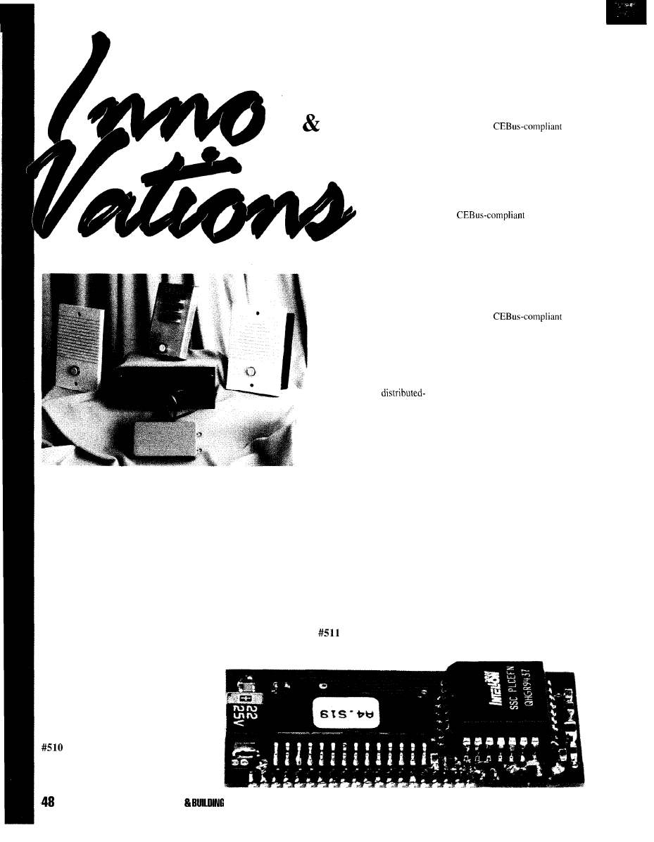
IN HOME
AUTOMATION
BUILDING
CONTROL
TELEPHONE SECURITY INTERCOM
The Tu-Dor Doorman is an intercom which enables a doorbell
to be answered from any telephone. The system is compatible with
commercial or single-line phone systems and does not require a
dedicated trunk port to operate.
The Doorman requires the installation of a bell or buzzer. When
someone activates the bell by pushing the door button, the occupant
picks up the phone and is automatically connected to the door
station. The system is compatible with cordless phones and is
particularly useful when employees and security people are working
alone and need flexibility in responding to doors.
Door stations are available in plastic or stainless steel. The
system can be upgraded to include remote door-strike activation.
Prices start at less than $200.
Solutions Worldwide
P.O. Box 8110-812
Blaine, WA 98231
(604) 582-4806
Fax: (604) 582-4386
edited by
Harv Weiner
SIMPLIFIED WIRELESS
CONTROL NETWORKS
The promise of intelligent
control networks for home and
commercial automation took a
great leap forward when Intellon
unveiled CENode Points, a new
family of network components
that lets manufacturers easily
embed wireless,
control capabilities within their
products.
Based on CEBus, the
industry-standard communica-
tions protocol for home
networks, the CENode Points
family provides a set of CEBus-
compliant building blocks that
can be easily integrated into
home appliances, lighting,
security systems, utility meters,
heating and cooling systems,
phone systems, and other
Intellon Corp.
residential electronics.
The CENode Points family
provides two classes of
components: Connection Points
and Application Points.
Connection Points offer a
complete
network interface for power line
(PL) or radio frequency (RF)
communications. Connection
Points ensure that OEM
products are interoperable with
any other manufacturer’s
products.
They also provide a standard
microprocessor interface to the
CEBus network and consistency
between different kinds of
communications media such as
PL and RF.
Application Points offer
complete
application implementations for
simple sense and control
functions. Users only need to
provide their own application
circuitry and packaging to
produce a complete CEBus-
compliant product.
CENode Connection Points
for PL applications are available
for $20 in OEM volumes.
CENode Connections Points for
RF applications will be available
in the third quarter of 1995.
5100 West Silver Springs Blvd.
l
Ocala, FL 34482
(904) 237-7416, Ext. 204
l
Fax: (904) 237-7616
JULY 1995 HOME AUTOMATION
CONTROL
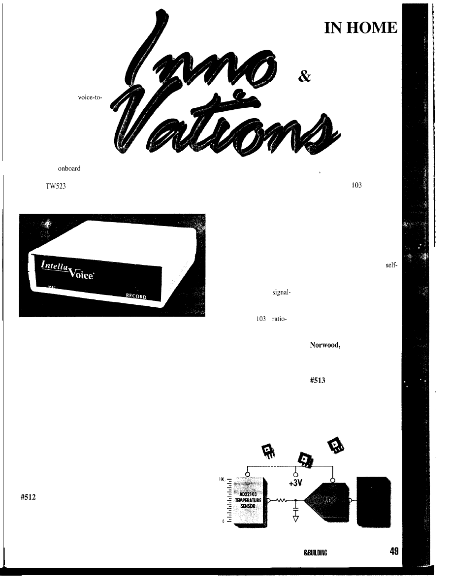
X-10 SPEAKS
IntellaVoice, a stand-alone
X-IO message controller
from
Intella-Home, provides voice
annunciation for X-IO-based
home automation systems.
Owners customize their own
announcements to accompany
key X-IO events. The
EEPROM storage retains
messages even without power.
Its built-in microphone and
automatic-gain circuits produce
high-quality natural voice
reproduction. Up to eight, nearly
10-s announcements can be
recorded. The
processor
monitors the power line using
the X-IO
interface for key event commands, then plays the
correct announcement for that event.
Intella-Home, a security and home automation installer for over
four years. has been using its IntellaVoice units exclusively in private
installations up to now. Announcements can be heard through the
built-in speaker or sent to whole-house audio systems through the
supplied auxiliary output jack. Owners of automated homes can
enjoy a personal wake-up message while the coffee is brewing or a
bedside warning when a yard motion detector is triggered.
IntellaVoice can even announce hidden automation activity like
“lowering air conditioning” or “water heater’s off.” The unit comes
preprogrammed to accept voice messages without extensive user
setup and may be recorded thousands of times without loss of
quality.
IntellaVoice sells for $379.
Intella-Home, Inc.
P.O. Box 780392
l
Sebastian, FL 32958
(407) 589-0970
3-V TEMPERATURE
SENSOR
Analog Devices introduces
a 3-V temperature sensor IC
with a voltage output guaranteed
to exhibit accuracy better than
2°C and nonlinearity better than
0.5% over its full 0-100°C
temperature range. The
AD22103
offers high gain and
direct connection to standard
analog-to-digital converters and
requires no additional
conditioning circuitry or
linearity compensation.
The AD22
is
metric, providing sustained
precision operation as battery
voltage levels decrease. The IC
is housed in small TO-92 or SO-
8 packages and is well-suited for
temperature-monitoring
solutions in computers, cellular
and cordless telephones, as well
as portable and low-power
electronic equipment.
CONTROL
AUTOMATION
BUILDING
The AD22
is equipped
with on-chip linearization and
signal conditioning. These
features eliminate external
signal-conditioning circuitry and
reduce sensor-system develop-
ment costs. Since the sensor
dissipates very little power, it
contributes no appreciable
system heat, eliminating the
heating errors associated with
other electronic temperature
sensors.
The AD22103 sells for
$0.98 in IOOO-piece quantities.
Analog Devices
One Technology Way
MA 02062-9106
(617) 937-1428
Fax: (617) 821-4273
HOME AUTOMATION
CONTROL JULY 1995

his project started
as an exercise in
software portability
and fuzzy logic.
After working on
microcontroller
projects for years,
we
wanted to look
at some of the issues in porting
software between execution plat-
forms.
We chose a fuzzy-logic-based
home environment control system
because it’s an application that is well
understood and offers many opportu-
nities for experimentation. As well,
we can put a fuzzy-logic tool that
we’ve been using through the paces.
The tool extends C to linguistic
variables as well as conventional
and 16-bit integers.
FUZZY LOGIC
Fuzzy
logic adds the concept of
linguistic variables to the variable
types most people are familiar with.
Linguistic variables describe data
in application-specific terms. We can
say, for example, that the day is hot.
Further, we can qualify the linguistic
term by scaling it between fuzzy 0
and fuzzy 1 (usually represented by 0
and 255). A hot day might have a
crisp value of 100°F and a linguistic
value of fuzzy 1. At
it is barely
hot (perhaps fuzzy 0.2). At 40°F or
so, it is not hot at all.
Our ability to naturally describe
our problems in linguistic terms
makes fuzzy logic easy to use. A
fuzzy rule might be:
IF room IS hot THEN
ac is on-high
This rule refers to two linguistic
variables
hot
and
on-high.
It is
interesting that linguistic variables are
context sensitive.
It has been a few years since interest in
fuzzy-logic technology for embedded
applications started. And, it is surprising that
computing has taken so long to accept
logic technology. For the most part, fuzzy
logic presents a cleaner, clearer interface to
the real world-a way of expressing
ourselves in terms of technology’s applica-
tion, and not in terms of the fundamental
science on which the technology is based.
One problem with finding suitable
applications comes from attempts to
implement applications in fuzzy logic based
on the underlying science of an application.
We were competing with implementations of
the science describing a real-world applica-
tion, rather than two implementations of an
actual application.
This small difference is significant.
Most scientific application models are linear
representations of the application. Imple-
mentations with fuzzy logic at best equal
alternative implementations. On the other
hand, many contain some nonlinear aspects,
which fuzzy logic easily handles.
For example, consider a simple
thermostat control system for a living room.
To control the temperature, we start with two
decisions: “when the room is cold, turn on
0 10 20 30 40 50 60 70 80 90 100
Temperature (“F)
Figure
1:
pares room temperature
with degree of member-
ship to determine the
HOT.
WALTER BANKS,
After reminding us of the basics of
fuzzy logic, Walter and his
associates concentrate on the
needs of environmental control.
They specifically look at some of
the implementation quirks that
come with writing fuzzy logic code
for a home-control system.
HOME AUTOMATION BUILDING CONTROL JULY
5 1
There is nothing critical about either component layout or wiring on this fuzzy-logic thermostat
prototype board. Clock speeds are low and the analog signals (O-5 V) are significantly above the noise levels
on the board.
the heat” or “when the room is too hot, turn
off the heat.”
We express these ideas formally to the
computer with the following rules:
IF room IS Cold THEN heat IS on
IF room IS Hot THEN heat IS off
Now,
suppose we move to Arizona, where
there are cold and hot temperatures. To cope
with the heat, we add rules to our system:
IF the room IS Cold THEN
IS off:
IF the room IS Hot THEN
IS on;
The control system is implemented so that it
gathers a collection of independent thoughts
about a problem presuming that each idea is
part of the total solution.
This all sounds good, but will it work?
We’ve introduced the concept of linguistic
variables that have some meaning in the real
world. Let’s look at the linguistic variable,
“room IS Hot."
room
really indicates room temperature,
so let’s build a scale of temperature on the
axis. On the y-axis, we normalize our
conclusions between 0 and (Boolean logic
has only two values 0 and while fuzzy
logic has all the analog values of O-1
We begin with
which we all
agree is hot. We set that value to 1. We also
agree that 90°F is still hot, so its value is as
well. At
we begin to have differing
opinions. Some people say 70°F is not really
hot, while others still insist it is. To account
for differing opinions, we set the value at
70” to 0.5. Finally, when the temperature
drops to
we all agree it’s no longer
hot. We set the value there to 0. Figure 1
graphically depicts this change in member-
ship.
Now that we’ve defined the linguistic
term
HOT
for our computer, it’s simple to
write a subroutine. On a scale between 0 and
the code needs to return how relevant
HOT
is given a temperature value. For
more granularity, increase the range
of possible return values from, for
example, 0 to 255.
The code only requires a few
instructions to implement on most
computers, even the simple ones used
in household appliances.
HOT,
in this
example, describes a condition in the
room (i.e., it is a member of room).
The code fragment in Listing 1
passed through Fuzz-C, a software
preprocessor. The linguistic variable
HOT
is defined as a trapezoid (i.e., it
has four arguments). The arguments
are formed from the crisp intersection
for each comer of the trapezoid.
The Fuzz-C preprocessor
generates C code from this definition
(see Listing 2). As you can see, it does
two things. First, it declares
room as
type c h a
r
(its crisp value), and
second, it generates a function which
takes the room temperature as an
argument and returns a value between
fuzzy 0 and fuzzy indicating the
relevance of linguistic variable
HOT.
Even though Listing 2 shows just
one linguistic variable, in this
application, the crisp variable room
1: The linguistic variable
HOT
is dejined as a having a trapezoidal-shaped membership
function. The definition corresponds to the graph.
LINGUISTIC room TYPE char MIN 0 MAX 150
MEMBER hot 60,
150, 150
This code translates the linguistic variablefrom a definition to an executablefunction.
The function can be easily implemented on most small embedded microcontrollers.
char
room:
char
(char
if
return(O);
else
if
6 0
else
*
+
1995 HOME AUTOMATION
CONTROL
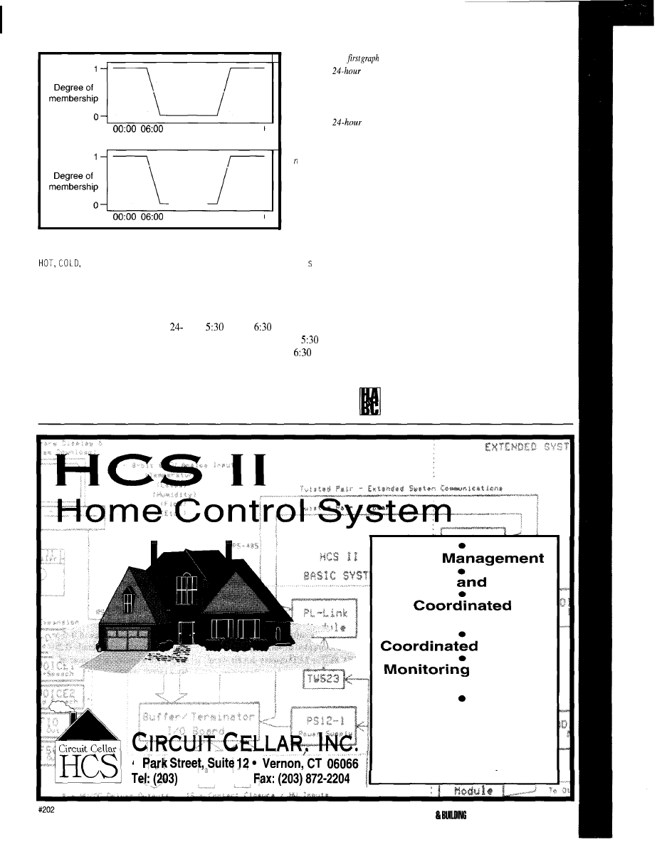
12:00 18:00 24:00
12:00 18:00 24:00
may have many linguistic members:
and
NORMAL.
Somewhat more interesting are
the linguistic variable’s declarations
related to time of day. With the goal
of referring to time in terms we use,
divide the day into 240 parts. In a
h day, 6-minute resolution nicely fits
into an X-bit variable while still
providing the resolution necessary to
deal with control problems.
In our application, there are six
linguistic variables in a 24-h period:
Figure 2:
‘The
compares
time
and linguistic variables
day (green) and night
(red). The lower graph
compares
time
and linguistic variables
morning, evening, and
i gh t setback (red).
day,night,morning,evening,daysb
(day setback), and n
i g h t b
(night setback).
It is easy to add more linguistic variables
or to change the way they are defined or
used.
day
is defined as a trapezoid starting at
A
.
M
.
By
A
.
M
.,
it is fully day and
continues to be so until
P
.
M
.
when it
starts to taper off. By
P
.
M
.,
it is no
longer day.
night
is definedas
NOT day.
n i g h t
therefore is a complement of
day
and the sum of
day
and
n i g h t's
degree of memberships is always
fuzzy-one.
The linguistic variables
morn i n g
and
even
i n g
are declared with trapezoids in the
same manner, except with the appropriate
time periods.
n i g h t s b,
the last linguistic variable,
also uses a fuzzy expression. It has been
declared as
n i g h t
not including even i n
g
Similarly,
days b
is also a fuzzy expression
stating the day setback temperature time is
day not including
morning
and
evening.
Fuzz-C enables you to use variables
instead of constants to declare linguistic
variables. Using fuzzy expressions to
generate some of the linguistic variables
results in a few fixed variables which define
several linguistic variables.
Generating code to produce degrees of
membership is not difficult--either by hand
or with some development aid. Figure 2 and
Listing 3 offer a full definition of the
linguistic variables associated with time on
the thermostat project.
H A R D W A R E
The fuzzy logic thermostat prototype
(see Figure 3) was implemented around a
4
875-2751
l
Energy
Security
Alarm
Home Theater
Lighting
and Data
Collection
Get all these capabilities and
more with the Circuit Cellar
HCS II. Call, write, or
FAX us
for a brochure. Available as-
sembled or as a kit.
HOME AUTOMATION
CONTROL JULY
1995
53
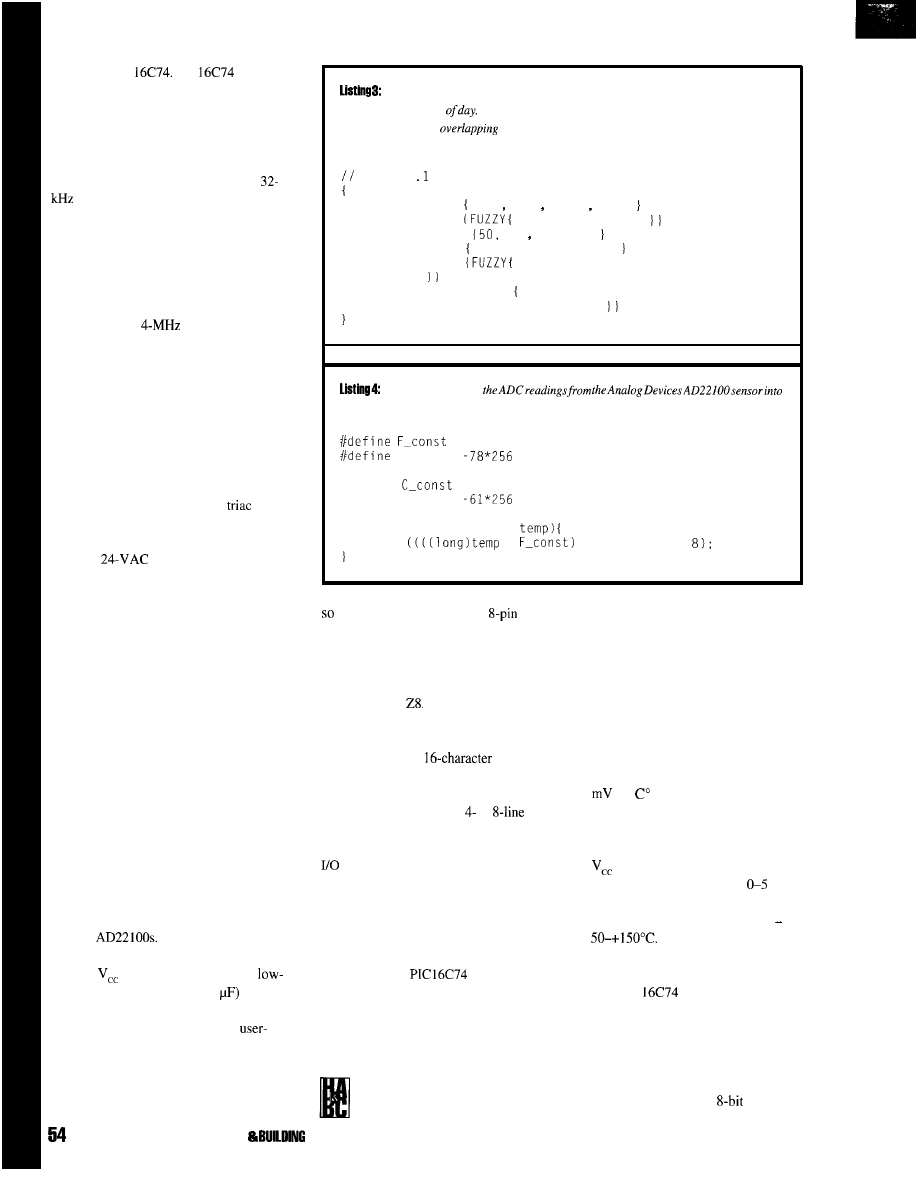
Microchip PIC
The
was used
for the prototype because it met all the
requirements of our project: several analog
inputs, low-power capability, and more
ROM space than we expected to need even
for performance-data gathering.
The design was expected to use a
crystal for the processor clock. While
building the prototype, we decided it would
be useful to add a serial port so a PC could
monitor the execution of the fuzzy-logic
controller. The serial port meant we needed a
faster processor clock so we could keep up
with the serial data port. During develop-
ment, we used a
crystal.
Household thermostats have standard
wiring in most homes. The heating, air
conditioning, and fan systems are controlled
by contact closures to a 24-VAC supply. The
humidifier relay is a contact closure brought
out to two terminals. Although it appears
that some form of triac-based electronic
switch could be easily used, one of us had an
experience where a new high-efficiency
system would not operate with a
switch.
Instead, we used a relay that is compatible
with a broad spectrum of heating systems.
The
supply lines to the
thermostat power the fuzzy-logic thermostat
controller. The 24-VAC supply passes
through a bridge rectifier, and a series
resistor limits the power dispassion of the
7805 5-V regulator. We provided a simple
power-fail detection circuit to allow the
software to turn off the heating, air condi-
tioning, and LCD display.
During a power failure, the software
needs to maintain only the date and time. In
the prototype, we divided one of the ports
into two 4-bit portions. Four of the bits
control the output relays for heating, air
conditioning, fan, and humidifier. The
remaining four bits sense key presses.
A 4-key keypad makes contact closure
to ground with 10-k pull-up resistors. The
keys are labeled Mode, Up, Down, and Next.
Software filters the key bounce.
The temperature sensors are Analog
Devices
These three terminal
sensors are easy to use-just connect
between
and ground. We used the
pass filter (1 k followed by 0.1
recommend by Analog Devices.
The NVRAM stores all of the
definable parameters such as room tempera-
ture setpoints and day and night setbacks.
The NVRAM is a serial memory part with
data and address information passed serially
The linguistic variables associated with the crisp variable hours define common
references to the time
The shape of the membershipfunctions allow smooth transitions
between adjacent or
time periods.
LINGUISTIC hours TYPE char MIN 0 MAX 240
hours; hour 0 240 for a day
MEMBER day
55 65 175 185
MEMBER night
hours IS NOT day
MEMBER morning
60 80 , 90
MEMBER evening 160 ,170 ,190 , 200
MEMBER nightsb
hours IS night AND hours IS NOT
evening
MEMBER daysb
(FUZZY hours IS day AND hours IS NOT
evening AND hours IS NOT morning
This routineconverts
actual temperature readings.
400
F-offset
#define
222
#define C-offset
char convert-temp (char
return
*
+ F-offset) >>
it can be implemented in an
part.
temperature sensing. Three-terminal
This device is commonly used in consumer
temperature sensors have made
and industrial devices. The NVRAM code is
temperature measurements by
another example of reusable driver code that
microcontroller-based systems very
originally came from a modem application
easy. The sensor is designed for
using the Zilog
JULY 1895 HOME AUTOMATION
CONTROL
DISPLAY DESIGN
The two-line,
display
shows current room temperature, humidity,
and outdoor temperature. The display is a
standard LCD driven by a
or
interface. Since both interfaces are available,
only interface speed and available processor
lines need be considered.
The display’s software interface has
been well documented in various publica-
tions (INK 8). The LCD display drivers were
initially written in C for a barcode reader
about 5 years ago. We simply recompiled the
C source for the
(we’ve used this
same source code with several
microcontrollers).
TEMPERATURE CONVERSION
As we mentioned before, we
chose the Analog Devices
AD22100 for indoor and outdoor
automotive applications that normally
experience wide temperature swings.
Unlike the thermistors typically
used for temperature measurement,
this sensor delivers a very linear 22.5
per
(other equally suitable
solid-state sensors of this type are
offered by other silicon vendors).
This temperature sensor requires
and ground and produces an
analog signal in the range of
V.
The working range is actually 0.25-
4.75 V for a temperature range of
Although this range is a
little coarse for precision, it’s
acceptable for a home thermostat.
The
we employed for the
prototype has eight 8-bit A/D
converters each with a range of O-5 V
If precision is needed, it is possible to
implement the ADC inputs with
expanded scales only to cover a
limited range, but with
accuracy
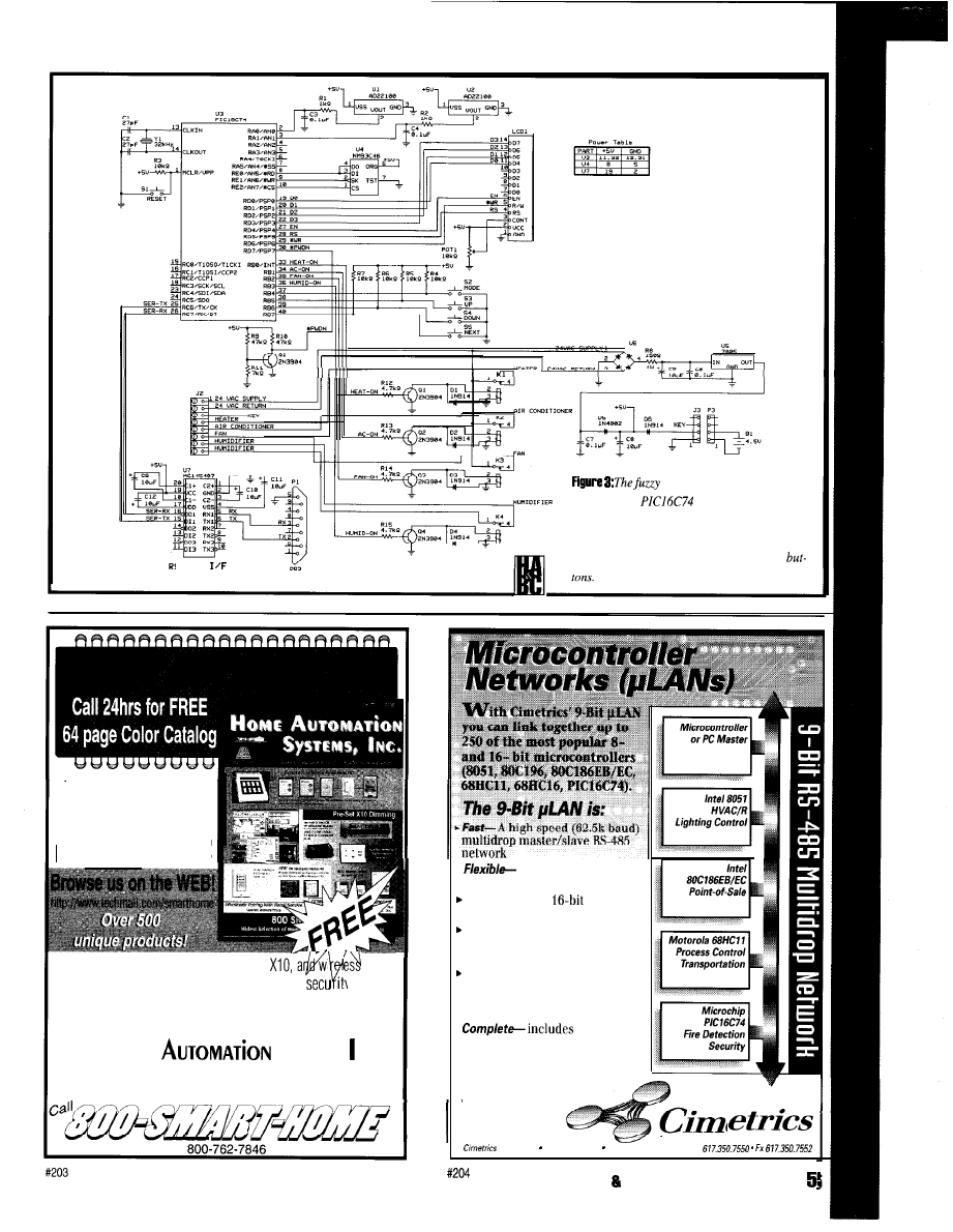
HVAC controller is based on
a Microchip
microcontroller. The
unit calls for heating, air conditioning, fan, and
humidity using simple relays. The user interface
S-232
is through a small LCD display and push
Largest Selection of
HOME AUTOMATION
products in the World!
Hundreds of hard-to-find automation,
control
products. Computer control of your home,
ity systems,
surveillance cameras, infra red audio/video control, HVAC,
pet care automation, wiring supplies, and much, much more!
H
OME
S
Y S T E M S
,
NC
.
151 Kalmus Drive, Ste L4, Costa Mesa, CA 92626
Questions 714-708-0610 FAX 714-708-0614
.
compatible with your
microcontrollers
Reliable-robust
CRC and
sequence number error checking
Efficient- low
microcontroller
resource requirements (uses
your chip’s built-in serial port)
Friend/y-
Simple to use C and
assembly language software
libraries, with demonstration
programs
.
network
software, network monitor and
RS-485 hardware
.
Practical-
applications
include data acquisition and
distributed control
T
E
C
H
N
O
L
O
G
Y
Technology 55 Temple Place Boston, MA 0211 l-1300. Ph
HOME AUTOMATION
BUILDING CONTROL JULY 1995
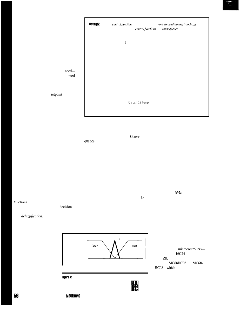
We translated the A/D converter value
to actual temperature by multiplying by a
constant and adding a zero-count offset.
Since we know the environment’s working
range, we don’t need range checks on the
data. In Listing 4, the code converts the
ADC result to Fahrenheit. Constants for
Celsius are also given.
PUTTING IT ALL
TOGETHER
We now have all the pieces we
displays, keypad, temperature sensors,
relay outputs, and definitions for time and
comfort. Although we define our comfort in
absolute temperature terms, it is easier to use
a conventional thermostat
to set the
desired temperature and let the linguistic
functions of comfort
(COLD, NORMAL, and
HOT)
be based on the relative temperature
error. Figure 4 shows the temperature
comfort of the room. A value of 0 means the
room’s temperature is at the setpoint.
As we established earlier, fuzzy rules
are a series of individual statements about
the problem. Listing 5’s partial source of the
fuzzy-control block shows some of the
rules
used in this project.
The first few rules are obvious. We then
move to the energy-saving rules. Here, given
information we have about inside and
outside temperatures, we make choices based
on natural warming or cooling.
With multiple rules, we have to decide
how we want the computer to evaluate an
outcome. Typically, it would evaluate each
rule independently and weigh each rule by
the strength of its logical argument.
Another method involves
consequence
These functions are fuzzy logic’s
way of resolving conflicts in the
making process and provide what is referred
to as
Fuzzy literature details
many ways of doing this, each author
extolling the virtues of a preferred method.
We used one of the
Thisjiizzy
regulates the heating
rules.
Fuzzy rules are independent intuitive
The
functions resolve the
actual control settings for heat and air conditioning.
FUZZY room_control
IF room IS cold THEN
ac
IS OFF
heat IS ON
IF room IS normal THEN
ac
IS OFF
heat IS OFF
IF room IS hot THEN
ac
IS ON
heat IS OFF
IF room IS cold AND OutsideTemp IS hot THEN
heat IS OFF
IF room IS hot AND
IS cold THEN
ac IS OFF
functions still are able to resolve
This project has simple on and off
actions even though the control calculations
different control schemes with varied inputs
are done for continuous control.
(see Listing 6).
photo shows the noncritical nature of
the O-5-V range. Layout of the digital
the construction of the project. All of
signals is noncritical due to the low
the analog signals are noncritical in
clock speeds used in this project.
All of this is tied together with a C
ma i n
function shown in Listing 7. This
function is conventional controller code
which reads the indoor and outdoor
temperature, calls the fuzzy-control function,
then calls the LCD information display
routine. The day and night setback routines
are an unusual use of a linguistic variable
that gives a smooth temperature transition
throughout the day. The define for N
i g h
Setback
shows how linguistic functions
may be called individually.
PROTOTYPE
We built the prototype system on a
small development board (see Photo I). The
standard methods called
center
I
of
gravity
for our consequence
functions. In general; this
method sums the results and
the weight (degree of
membership) of each input,
and computes a single answer
Normal
1
Degree of
membership
0
-100
-8
-3 0 3 8
100
to accurately reflect all of the
I
Room
results. In effect, center of
I
gravity provides smooth
You can
combine linguistic terms toprovide
transitions between competing
for room variables as a function of temperature
terms.
errors: normal (bold), cold, and hot.
JULY 1995 HOME AUTOMATION
CONTROL
We made a number of small
changes to the design to accommodate
the developmental nature of the
project. First, we added a serial port to
the processor so we could monitor the
internal state of the thermostat. To
achieve acceptable serial data rates,
we increased the processor’s clock
speed from 32
to 4.00 MHz.
While this has little effect on the
prototype, it increases battery drain
when conventional power fails.
In hindsight, the serial port could
be useful. As well as fulfilling a
monitoring function, it could set the
thermostat’s operating parameters.
PROJECT PORTABILITY
Within the last few years, most
manufacturers have introduced
versions of their
Microchip PIC
(what we used),
Zilog
National COP8, and
Motorola
and
meet this project’s
requirements. We didn’t discount the
805 1 families, but were more familiar
with software tools for the rest of the
chips mentioned.
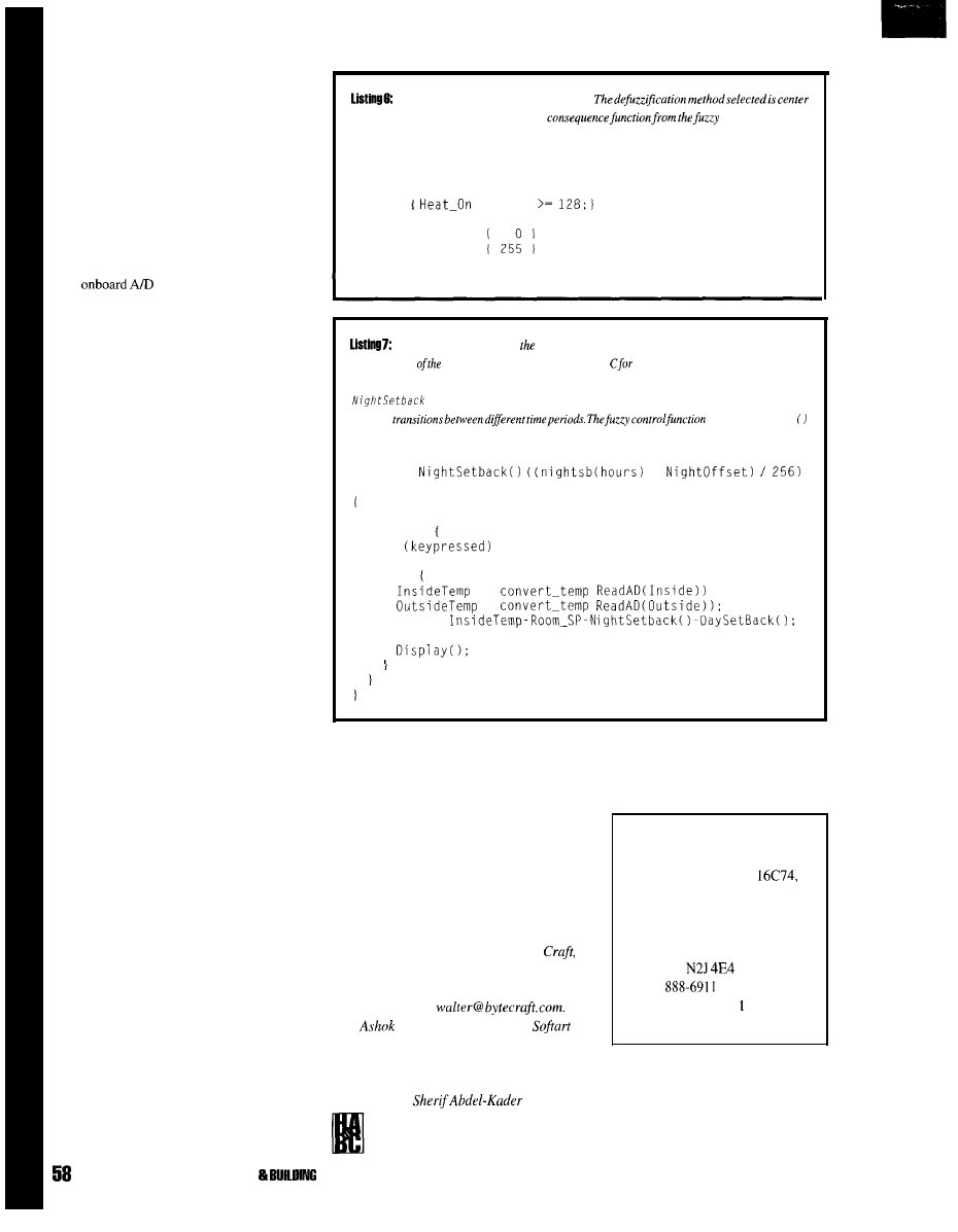
We recompiled the source code for the
project on each of the above microcontroller
platforms. In each case, the necessary
changes to the source code were limited to
replacing the processor descriptor header
files and making minor changes to port and
bit assignments.
The most significant change is the A/D
conversion method used on each of the
processors. Most of the embedded B-bit
processors have at least one family member
with
conversion capability.
Realistically, you could produce a demon-
stration board with several processor
sockets-ne for each supported processor.
FUZZ-C
We used the Fuzz-C preprocessor to
add linguistic variables to our C program.
This inexpensive preprocessor works with
almost any C compiler. Fuzz-C is actually
implemented as a simple compiler: it reads
in a mixture of C and fuzzy-logic declara-
tions and functions and reproduces the C
unchanged. The fuzzy logic is translated into
its C equivalent.
Like most fuzzy-logic projects, this one
contains a little fuzzy-logic-related code
(linguistic variables, consequence functions,
and fuzzy-logic control functions). It also
has a lot of traditional code required to scan
keyboards, drive displays, control relays, and
send and
receive serial characters.
Fuzzy logic is starting to be seen as a
tool that can add significantly to a
developer’s ability to describe a problem.
Fuzzy-logic techniques enable developers to
deal with applications that are not well
defined in the crisp sense or have many
different operating parameters, some of
which may be nonlinear.
The files posted on Circuit Cellar BBS
contain both the source code for the project
and the intermediate C code and its compiled
form. You can easily retarget the intermedi-
ate C code for other platforms.
FUTURE WORK
It’s reasonable to tie the thermostat to a
central home controller bus such as that used
by the HCS II. You could then centrally
control and monitor an HVAC system and
room environments.
All engineering projects fall victim to
three fundamental shortages: lack of
information, time, and resources. Of the
three, the last is the easiest to solve and the
first, impossible.
Here’s theconsequencefunctionforheat.
of gravity, which means each call to the
rules is weighted.
After all of the rules have been executed, the consequence
function
returns a fuzzy result. The
action statement turns the heat on if the result is greater or equal to 128.
CONSEQUENCE heat TYPE char MIN 0 MAX 255 OEFUZZ cg
ACTION
= heat
MEMBER OFF
MEMBER ON
The complete mainlinefor
fuzzy
home environment controller
ends up being very
simple. Most
software in
this
system is ordinary
scanning
keyboards, updating time,
driving displays.
A
little of the code is dedicated to linguistic variables
and
fuzzy
functions.
shows another way that the linguistic variable nightsb may be used to get
smooth
room_con t ro 1
is called as a C subroutine.
#define
*
void main (void)
Init_allO;
while(l)
if
Service_mode;
else
=
=
room =
room_controlO;
Probing the problem illuminates the
science involved, but to achieve results, we
must still accomplish the engineering.
Fuzzy-logic-based systems address both
science and engineering with a single
brilliant idea: “Why not describe the final
solution to the problem intuitively?’
Engineering and science then become side
effects of the solution rather than the other
way around.
Walter Banks is the President of Byte
a company specializing in code creation
tools for embedded microcontrollers. He
may be
reached at
Pate1 is the president of
Microsystems where he does hardware and
software designs using microcontrollers for
the communications industry.
is a
software support specialist
of
Byte
Craft. He is a graduate from the
University of Cairo has extensive
experience in both embedded systems
development and customer support.
SOURCE
MPC compiler for PIC
Fuzz-C
Byte Craft Limited
421 King St. N.
Waterloo, Ontario
Canada
(5 19)
Fax: (5 19) 746-675
info@bytecraft.com
I R S
413 Very Useful
414 Moderately Useful
415 Not Useful
JULY 1995 HOME AUTOMATION
CONTROL
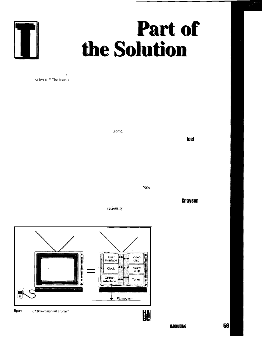
he January 1980
cover of
BYTE is
Robert Tinney’s
CAL:
classic painting of a
futuristic home
computer in an
elegantly carved
wooden cabinet. A
hand-held RF remote-control device
lies next to it on the table. The
computer’s screen reads, “MADAM
DINNER IS
theme is domesticated computers and
the lead article is Steve Ciarcia’s
“Computerize a Home.”
The article describes an interface
between a home computer and a new
gadget on the market, a BSR (X- 10)
power-line carrier controller and light
switch. For many people, including
myself, who struggled in the early
’80s to make domesticated computers
into a business, this article represents
the beginning of what we now call
“home automation.”
On page 91 of the same issue is a
boring, black and white ad by a small
company called Microsoft that
promotes their only product, a simple
BASIC compiler (yawn).
computer and have a wealth of
hardware and software that performs
truly beneficial, educational, and
entertaining tasks.
A lot has happened since 1980.
Microsoft and home computers are
now big business. Consumers
understand the benefit of owning a
Home automation technology has
certainly improved..
There is more
press about home automation-more
gadgets, more modules, more stuff-but,
unfortunately, home automation remains in
its infancy. It is still more of a concept than a
product, still the domain of the technically
competent, and still struggling to be a
business.
How come?
and usable applications. Home automation
must make that same transition or it will
remain simply a
The transition requires three changes:
The answer is simple. Home automa-
tion has not made the transition that home
computers did in the late ’80s and early
It lacks a standardized bus, standardized OS,
1: Any
consists of a series of contexts at a network node
address.
GRAY SON EVANS
Need a better
tor what’s
required in programming a CEBus
application? If so, check out
Grayson’s article on CAL, the
Common Application language.
As a key member of the CEBus
committee,
brings us an
inside corner on the highest level
of CEBus specification.
HOME AUTOMATION
CONTROL JULY 1 BB5

l
a standardized physical
interface between
devices in the home so
information can be
easily and reliably
exchanged
l
a standardized way for
devices to interoperate
and talk to each other
using a common
language
l
a wealth of truly
beneficial applications
(i.e., things for devices
to do which are
available to the
consumer at reason-
able cost)
Aware of the
problem, the CEBus
Committee, sponsored by
the Electronic Industries
Association (EIA) and
made up of consumer
General
00
Universal
40 Environmental Zone
02
User Interface
41 Environmental
Sensor
04
Data Channel
42 Environmental Status
05
Time
43 Environmental Zone Control
10
Audio Amplifier
11
Medium Transport
12
Tuner
13
Video Display
14
Audio Equalizer
50 Utility Metering
51 Utility Monitoring
56 Energy Control
57 Energy Management
Liahting
Security
20
Light Sensor
60 Security Zone/Sensor
21
Lighting
61 Security System
22
Lighting Zone
62 Security Control
24
Lighting Zone Control
63 Security Alarm
Convenience
81
Window control
82
Door/Gate
84
Pool/Spa
70 Washer
72 Water heating
73 Dryer
74 Refrigerator/Freezer
1: Even
list
illustrates that every
electronic subsystem in the house can be addressed using CEBus.
product manufacturers (including home
computer manufacturers), worked to solve
the first two problems with the development
of EIA-600. The CEBus standard details the
physical interface, message protocol, and
language necessary to allow the third item
(consumer applications) to be developed.
This article takes a closer look at the
most important aspect of
interoperable language called CAL.
CAL
The CEBus Common Application
Language (CAL) defines what products say
to each other and was specifically developed
for residential product control. By establish-
ing a common product model and common
set of commands, residential products can
communicate with other products without
knowing how each specific product operates,
who built it, or what’s in it.
Unlike C or Pascal. CAL is a command
language consisting of two major parts:
l
the definition of a data structure that
models product operation
l
the description and syntax of the messages
that operate on the data structure.
CAL adheres to many object-oriented
principles typically found in languages such
as
but it is not an object-oriented
language.
CAL messages originate from and are
received and parsed by the CAL interpreter,
which is coded into the Application Layer
protocol software of all
products. The CAL interpreter is the heart of
any CEBus product, its design requirements
set early in its development. The CAL
interpreter must:
l
be common to all residential devices
l
perform both control and data acquisition
functions
l
perform network administration and
management functions
l
be reusable and extensible
l
be customizable
l
be simple enough to code in small
microcontrollers
CAL DATA STRUCTURE
The design of CAL assumes that
all electrical appliances and products
in the home have a hierarchical
structure of common parts and that the
operation of the common parts is
similar from product to product.
CAL treats each product as a
collection of one or more of these
common parts called
contexts.
A
context defines a functional subunit of
a product whose operation can be
defined and remains constant
regardless of where it’s used.
For instance, CAL does not
know how a TV operates because a
TV is too general a product category.
Depending on the TV, it could have a
clock, audio amplifier, tuner, and
built-in surround sound. However,
CAL does know how to operate
contexts, and all CEBus devices,
including TVs, consist of one or more
contexts.
A CEBus TV looks like a
collection of contexts at a network
node address (see Figure 1). Depend-
ing on the model’s features of the
model, a CEBus TV might contain
contexts for a video display, an audio
I 1 I
PL Medium
AMP CONTEXT
Figure
Each context consists of one or more objects. Four of the twenty Audio
Objects include Mute, Volume, Bass, and Treble.
60
JULY
1995
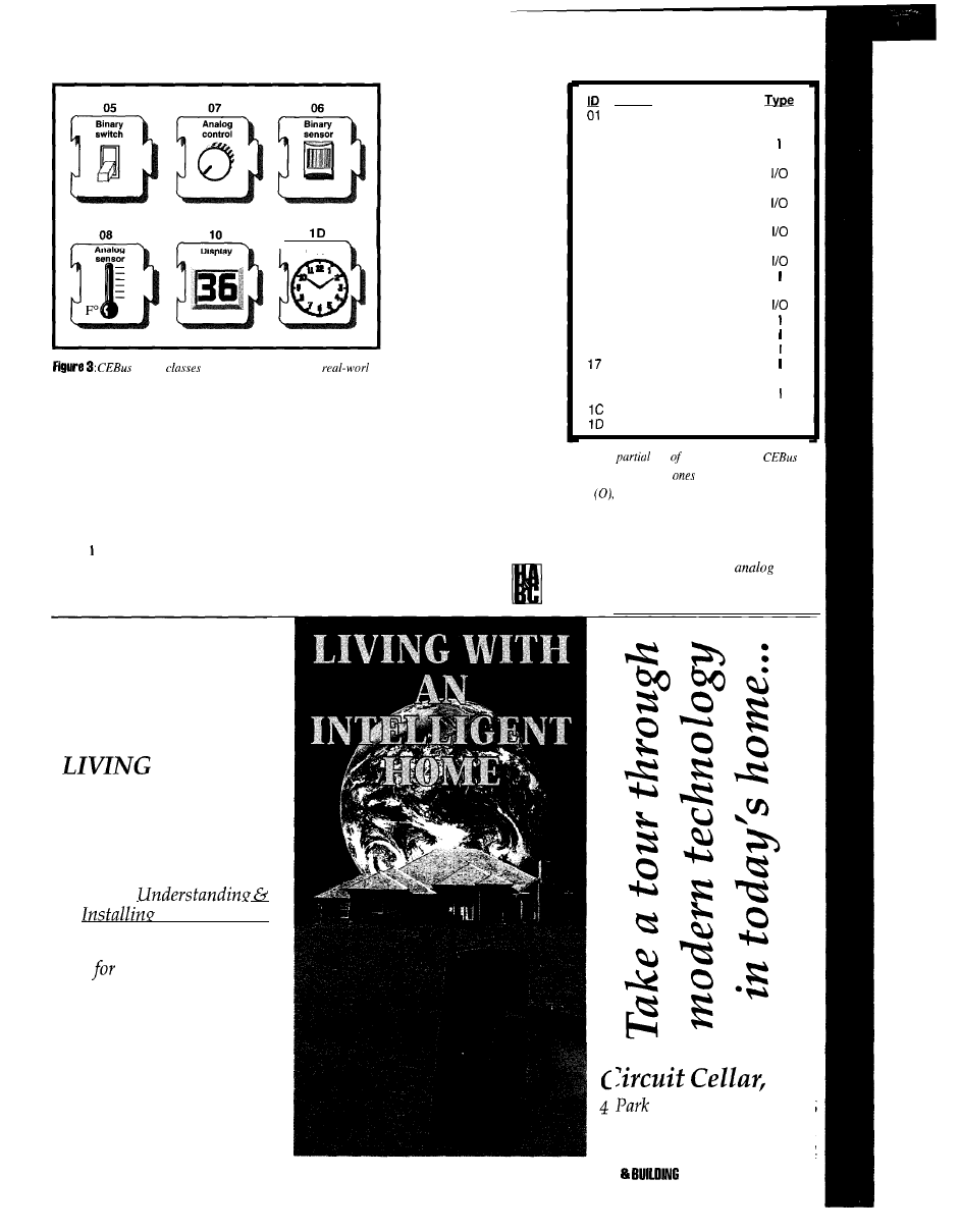
C l o c k
object
typically correspond to
devices. Objects are plug-and-play in each context.
amplifier, a tuner, a clock, a user
interface, and so on.
CAL defines more than 50
different contexts for everything from
lighting to security, heating and air
conditioning, washing and drying.
Table gives a partial context list.
Each context, regardless of what
product it’s in, operates the same way.
Find out how you can
add intelligence to any
home, at a cost that’s
within your budget.
WITH AN
INTELLIGENT
HOME
will change the way you live.
Written by David Gaddis,
author of
Home Sustems
This VHS video cassette retails
$24.95 plus $5 s&h.
It is being offered to
Circuit Cellar INK
subscribers for only $17.95
plus $4 s&h (U.S.)
ORDER TODAY!
Don’t let this exciting technology
opportunity pass you by!
The audio amplifier in the
TV, stereo receiver,
speaker phone, and
intercom all work alike.
If a CEBus product
knows how to set the
volume in the audio
context of one product, it
knows how to set the
volume in all products.
As shown in Figure
2, each context consists
of one or more objects.
Each object is a software
simulation (or model) of
a control function of a
context. Only 4 of the 20
objects specified
in the
actual
CEBus audio
context are shown. The volume, bass, and
treble analog-control objects, and the mute
binary-switch object represent control
functions typically found in audio amplifiers.
Objects model tasks performed by users
to control a product. To turn a light off or on,
use a switch, defined by CEBus as a
binary switch object.
To adjust the
stereo receiver’s volume or to raise
Object
Node Control
02
Context
Control
03 Data Channel Receiver
04 Data
Channel Transmitter
I
05 Binary Switch
06
Binary Sensor
0
07
Analog Control
08
Analog Sensor
0
09 Multiposition Switch
OA Multiposition Sensor
0
OB Matrix Switch
OF Meter
10
Display
I
11 Medium Transport
13
Dialer
15 List Memory
16 Data Memory
Motor
19
Tuner
I
1 A Tone Generator
Counter
0
Clock
0
Table 2:
A
list
the 25 possible
objects shows which
are input only (I), output
only
and input and output (I/O).
or
lower the thermostat’s temperature, use a
control (knob), defined as an
control
object.
All analog controls are similar. They
Inc.
St.
l
Vernon, CT 06066
Tel: (203) 8752752
Fax (203) 872-2204
HOME AUTOMATION
CONTROL JULY
1 9 9 5
61
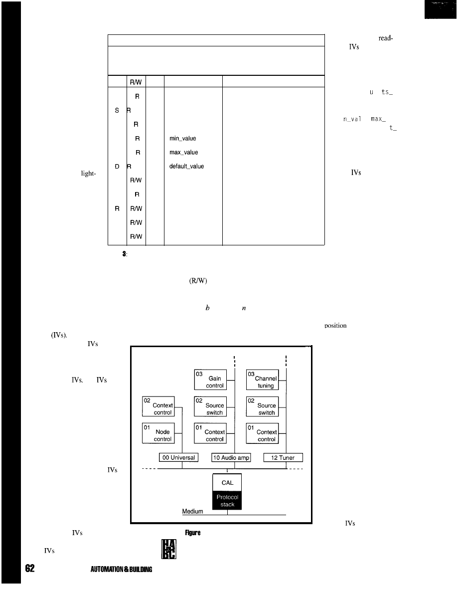
can be physically set to
any value between their
minimum and maximum
values.
Other controls found
on consumer products
include multiposition
switches (e.g., the switch
selecting the audio source
on the stereo receiver),
keypads, and so on.
Several sensor control
devices provide informa-
tion about a product
function. Analog sensors
(e.g., temperature or
level sensors) provide the
sensor the equivalent of an
analog control: they can
assume any value between
their minimum and
maximum values.
All objects are
defined by a class number
(see Figure 3). An object
class defines the generic
operation of the object.
(07) Analog control
Models operation of a continuously variable control such as knob, slider,
or analog setting device. Used to set a variable value for a function over a
range of values at a defined resolution.
IV
T y p e N a m e
IV description
U n
units-of-measure
Units of measure used
in context selected
n
step-size
Smallest increment that control
can bechanged
r
n
step-rate
Rate of change of control.
Zero implies instantaneous change
N n
Minimum value control can be set
M n
Maximum value control can be set
n
Default value control can be set
C
n
current-value
The current value of control
P n
previous_value
Used in reporting to track the
last value of C
d
reporting_condition
Test condition used in reporting
H
d
report-header
Report message body
A
d
report-address
Node address of report message
Table
The CEBus object table
for
the analog control object (07) offers a quick look up.
Generally,
only
provide
information for other
nodes on the network
about the application
of the object. For
example, the n i
of-measure, step_
s i z e , s t e p - r a t e ,
mi
ue,
value,
and
defaul
v a l u e I V s i n T a b l e 3
define the characteris-
tics of an object’s
particular use. None of
these
are required,
but they may be of
benefit to other nodes.
CONTEXT/
OBJECT DATA
STRUCTURE
As Figure 4
illustrates, the context
and object data
structure in a product
can be thought of as a
When an object is used in a specific context,
read/write
as referenced from the
it assumes a specific instantiation, such as
network and not internally to the product.
volume or temperature control, of a context’s
The third column shows the data type
function. Table 2 is a partial list of the 25
of the IV where is Boolean, is numeric
predefined objects usable in CAL.
(integer or real), c is a character string, and
d
Objects consist of a set of instance
is binary data.
tree structure. Incoming messages are
addressed to a specific object in a
specific context. Each context is
addressed by its class. The objects in
each context are addressed by their
sequential
in the context
variables
Like variables in
any software program,
have a
length or size and a data type. All
network operations on contexts are
performed by reading from and
writing to object
The
defining each object are listed in
the object tables of CAL specifica-
tion. There is a table for each of
the 25 objects.
Table 3 shows the analog
control object. The object class and
name are given in the definition’s
top line. The description section
gives the general use of the object
and is followed by a list of all
defined for an object class. An IV
label is an ASCII string of one or
more characters. The label is how
the IV is referenced in a message.
Any IV label and name in bold
type is required to be supported in
the object. Other
are optional.
The second column shows
which
are read-only (R) or
4: The tree structure of the context’s model in
a CEBus product hierarchically offers specific
controls.
starting at 01. The CAL
interpreter locates the object
and performs the command
in the incoming message on
object IV.
Every CEBus node
must contain the universal
context (00). The universal
context does not model any
functional system of a
product. Rather, it stores the
global CEBus housekeeping
information about the node
in the node control object.
The node control object
(01) is the location for
global device information
such as the system and node
address, the product serial
number, and other informa-
tion that applies to the entire
product.
in the node
control object simplify
product identification on the
network, perform address
JULY 1995 HOME
CONTROL
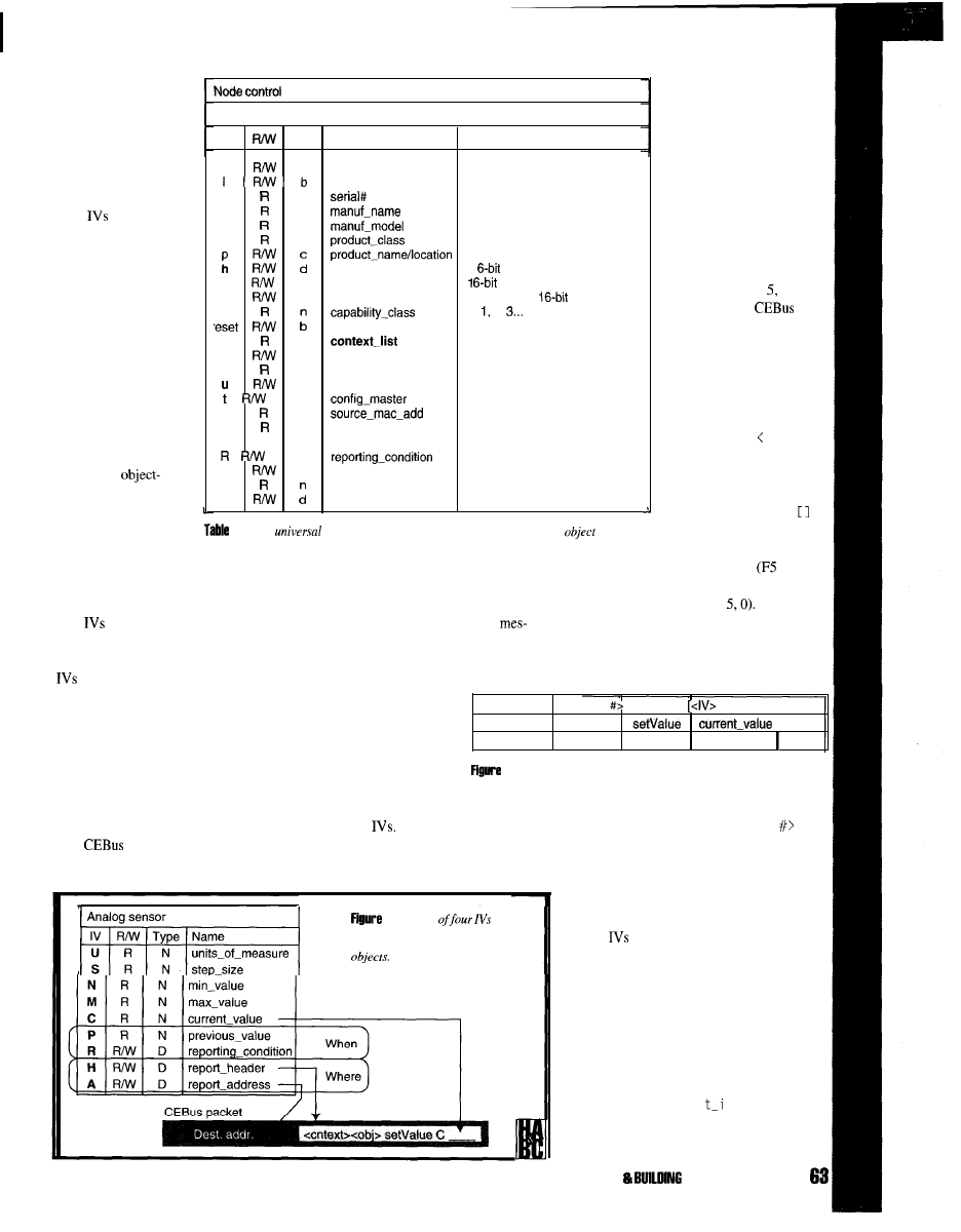
configuration, and
determine product
capability. Table 4
shows the contents of
the node control
object. While only the
bold IV must be used,
other
enhance
interoperability,
simplify field address
configuration, and
should be used.
OBJECT IMPLE-
MENTATION
Objects are coded
as a set of IV data
variables. Application
software is associated
with the variables.
Unlike objects in C++
and similar
oriented languages,
CAL object variables
are exposed to the
W
b
power
Device power, 0 = off, 1 = on
on-offline
Online/offline state of
device
S
c
Manuf. serial
n
c
Manuf. product name
m
c
Manuf. product model
C
c
Product class number
Location of product in house
system-address
1
system address
a
d
node-address
node address
g
d
group-address(s)
Zero or more
group addr.
b
0, 2,
reset
Resets device to factory defaults
0
d
List of
used contexts
in product
f
b
configured
1 = address configured
i
n
setup
Used during
n
user-feedback
User interface IV during
b
Indicate node is
d d
Node addr. of last received pkt.
e
d
source_system_addr
System addr. of last received pkt.
k
R/W d
authentication keys
One or more keys
d
H
b
reporting-header
A
reporting-address
P
previous-value
Of power IV (w)
IV), a response message is
returned.
The CAL command
message follows a specific
syntax. In Figure the
message sets a
light
to 50% brightness. The
message consists of a
<context ID>, <object
number>,
and
<method>,
optionally followed by an
IV and one or more IV
arguments. The >
characters enclose an
element identifier and may
be made up of one or more
simpler elements. The
4: In the
context, use the object table for the node control
(01).
characters enclose optional
network through the
parts. The
D
stands for a
CAL interpreter. The
delimiter token
hex).
application code that executes the
input, and input/output. The categories
As you can see, the argument in Figure
object’s function is hidden.
define whether the object primarily sends,
5 is the number 50 (ASCII
Numeric
may be thought of as the
receives, or both sends and receives
values are represented in messages as ASCII
interface between the product
sages. Objects, represented by one of three
since representation of a number in a product
application and the outside network.
symbols, correspond to the network type.
depends on how it’s implemented.
are read or written by any node on
object
(01) Node control
Required storage object of Universal Context
IV
T y p e N a m e
Context function
command message is sent
to a device to perform an
action such as setting or
reading the value of an IV.
If a command message is
sent that generates a return
value (such as reading an
the network (they can be protected
using authentication if necessary).
The application code does the
same. It checks for changed values
CAL MESSAGES
CAL messages are
generated by objects via the
CAL interpreter or the
<context ID> <object
<method>
[D <arguments>]]
Lighting
Light level
5 0
21
02
45
43 F5
35 30
and acts accordingly, or it updates the
values.
object’s application code.
Objects communicate with
5:
Here, the general message syntax shows a message to set a
light to a 50% brightness level.
OBJECT NETWORK TYPES
objects are divided into
three network categories: output,
other objects by setting or
reading their
There are two general types of
messages: command and response. The
6: This set
is used
in all output and input/output type
The <context
ID>
<object
pair
forms the destination object address for the
message. It identifies a particular object in a
particular context in the product.
The method identifies an action to be
performed by the CAL interpreter on one or
more
in an object. Methods are usually
used with one or more arguments, separated
by the delimiter token. Each method operates
on a specific data type. Table 5 lists a few
commonly used methods.
RESPONSE MESSAGES
A response message is generated by a
node whenever the node receives a message
that uses the
expl i ci
nvoke
applica-
tion-layer service, regardless of the com-
mand message. The general syntax for the
HOME AUTOMATION
CONTROL JULY 1999
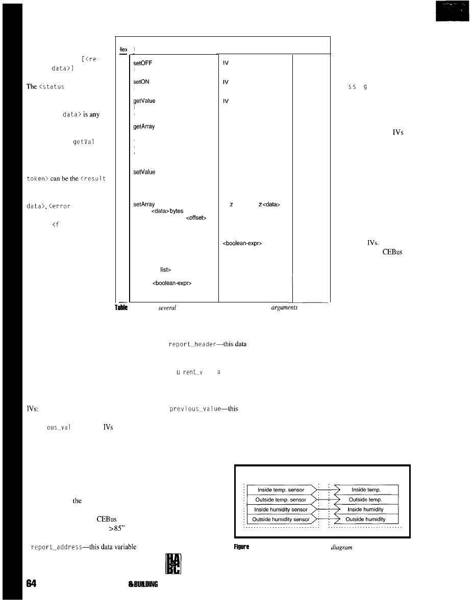
response ASDU is:
<status token>
turned
token>isa
one-byte indicator of the
type of response, and
<returned
data returned as a result of
the command message.
The method
ue
IV
returns the contents of
the IV in a response
message. The <status
completed token>
followedby
<returned
token>
followed by an error
number, or
a 1 se
to ken>
indicating a
Boolean expression in a
message evaluated false and
therefore not executed.
MESSAGE
GENERATION
Objects send messages
to other objects in one of
two ways. The object’s
application code generates a
message directly or it uses a
r
41
42
43
44
45
46
56
Method
Sets a boolean IV to 0 (FALSE)
Sets a boolean IV to 1 (TRUE)
Returns the contents of the IV
in a response message
Returns count number of bytes
of the data IV starting at the
offset byte. The default offset is
0 (beginning of the data), the
default count is all of the data.
Sets the IV to <value>. If no
<value> is given, the IV is set
to the object default value.
Stores
into a
data IV starting at an
number of bytes. The default
<offset> is 0 (beginning of the IV).
if
Used for the conditional exe-
cution of <message list> based
on the result of <boolean-exprz.
<message
can contain
any message that is valid for the
Object.
may
contain any IV that is used in
the Object.
Arauments
Operates on: Data types
B N C D
IV [z [<offset>] [z <count>]]
IV [z <value>]
IV [<offset>]
BEGIN
<message list>
[ELSE clause] END
Y N N N
Y N N N
Y Y Y N
N N N Y
Y Y Y N
N N N Y
5:
Here are
of the most common methods showing
and
applicable data types.
reporting condition to cause the CAL
interpreter to generate a message automati-
cally. The first case is called an application
message
and the second method is called a
reporting message.
Network output and input/output
objects contain a set of optional Reporting
reporting-condition,
report_header,report_address,
and
previ
ue.
These
are used as a
group by the CAL interpreter to determine
when and where to send a message to
another node. Their function is illustrated in
Figure 6.
l
report_condi ti
oh-this function
contains a Boolean expression describing
a condition in
object to test whether a
report message should be sent. The
function uses standard
Boolean
expression syntax (e.g., “C
(or 43
E4 38 35).
l
contains the node and system address of
the destination device.
l
variable
contains the CAL message to send to the
destination device (less the
c r
a 1 e
argument). The message
contains the context, object, method, and
IV. The
current_val ue
is appended to
the IV argument.
l
valueholdsthe
current_val ue
when the last message
was generated. It is used by the CAL
interpreter to compare the present value of
current-value.
It
is
automatically
updated by the
CAL interpreter
interconnect diagram for two HVAC
contexts. The environmental sensor
context (41) resides in a device that
measures temperature and/or
humidity. The objects bind to a set of
corresponding network input objects
in the environmental status context
(42). The environmental status
context is used in equipment that
needs to know the inside or outside
temperature or humidity (e.g., a
thermostat, TV, or PC).
whenever a report
is sent.
Environmental sensor (41)
Environmental status (42)
Whenever
report-condition
evaluates true,
the
message in
the
report-header
(with the
object’s
cur-
7: A simple context interconnect
shows the binding of
output objects to input objects. Contexts can contain any combination
of input, output, or input/output objects.
rent-value
appended)
is sent to the address in
report_addressto
update the
value
of
a
target
IV.The
report_
me a e
contains the
target context or object
address. The advantage
of using reporting is that
it is field programmable
since the reporting
can be written after
product installation.
OBJECT BINDING
Object binding
establishes an address
correspondence between
a network output object
and one or more network
input objects, usually
stored in the object
reporting
Most
objects in each
context are intended to
work (or bind) directly
with specific objects in
other contexts.
The binding is
expressed in the context
interconnect diagram.
Figure 7 shows a typical
example of a context
JULY 1885 HOME AUTOMATION
CONTROL
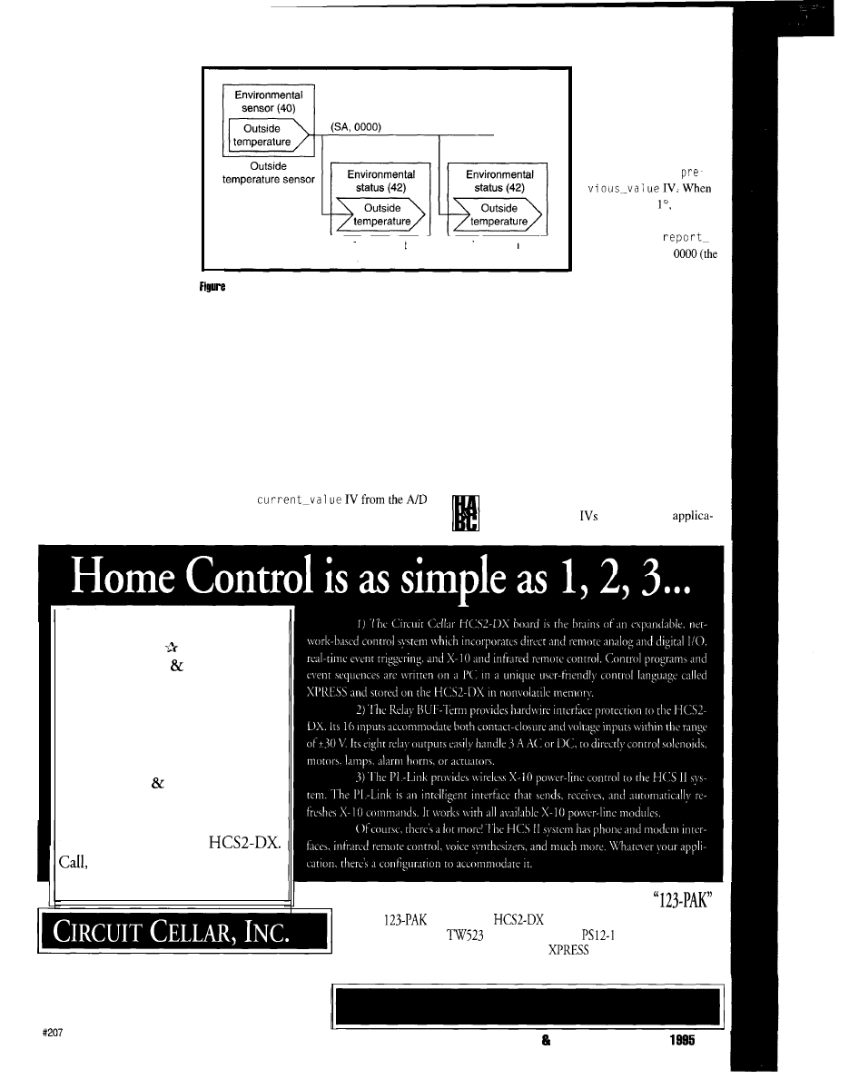
The objects in the
environmental
sensor
context
send messages
reporting a change in
temperature or humidity to
the environmental status
context. This design makes
interconnecting or binding
products in the field easy
since only the system and
node address of the device
containing the environmen-
tal status context needs to be
known.
A more general (and
desirable) binding does not
require the destination node
address. Figure 8 illustrates
Thermostat
Television
8: In general
binding via the broadcast node address, the outside tempera-
ture object message, which reports the current outside temperature, is picked up by
all node containing context 42, outside temperature object.
context 43, object 03
updates its c u
r rent_
v a 1 ue
to the most recent
temperature value. The message is executed
by any node in the house containing the
environmental status or outside temperature
object, such as the living room television and
the heat-pump thermostat. The application
code in the thermostat updates the outside
temperature display from the c u r rent_
value.
an outside temperature sensor device
containing the environmental sensor
context and uses the outside tempera-
ture object (03). This product is
intended to bind to all environmental
status or outside temperature objects
in the home. When the outside
temperature object sends a message
reporting an outside temperature, it
uses the broadcast node address
(0000) so it will be received by all nodes in
the house.
Figure 9 shows the implementation of
the outside temperature sensor product and
the thermostat. The outside sensor contains
the data structure for object 03 of the
environmental sensor context (41). The
application code updates the
converter. The
report-condition
Energy Management
Security Alarm
A
Coordinated Home Theater
A
Coordinated Lighting
A
Monitoring Data Collection
Get all these capabilities and more
with the Circuit Cellar
write, or fax us for a brochure.
Available assembled or as a kit.
4
Park Street, Vernon, CT 06066
(203) 875-2751
l
Fax (203) 872-2204
“C
1” says to send a
message any time the
current- v a
1 u e changes
by 1.
The CAL interpreter
checksthe
current_
valueagainst
the
they differ by
the
interpreter generates a new
message to the
address of
SA,
house system address or the
broadcast node address).
The message to
Note that in both products only the
objects and the
needed for the
GETSTARTED TODAYWITHAN HCS2
The
consists of an
board, Relay BUF-Term board,
PL-Link board,
power-line interface,
power supply,
serial cable, and V3.0 HCS
software.
Assembled $65 1
Kit $461
Prices shown are plus shipping.
HOME AUTOMATION BUILDING CONTROL JULY
65
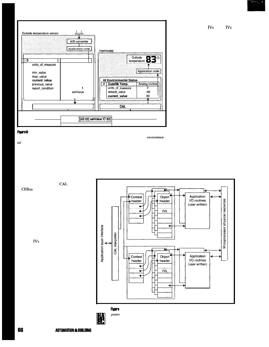
temperature sensor
r
l
41 Environmental Sensor
Outside Temp. Analog s e n s o r
step-size
report-header
report-address
F
1
-20
120
83
I
83
C <delta>
(42 03)
C f5
SA, 0000
CAL interpreter
interpreter
Transmitter packet
(SA, 0000)
T
Here’s an example of the outside temperature sensor device using only object 03
of
the
environmental sensor context. Messages are received by the inside thermostat containing the
status context, object 03.
that represents the implemented
contexts, objects, and
so that
can be read, written, and tested.
The data structure must also be
accessible from the device application
software. Figure 10 offers an example
context or object data structure
implemented as a series of linked
lists. The context list contains one list
element per context. The context
element contains a list of imple-
mented objects and a pointer to the
object IV data structure. The object
structure contains a pointer to the
application code (if any) associated
with the object.
Message parsing is straightfor-
ward. The interpreter looks at the
incoming message, determines
whether it can be performed based on
what is supported in the device, and
executes the method (Figure 11). If
anything about the message causes
parsing and execution to fail, an error
reply message must be generated.
tion are used. Binding via the broadcast node
address makes field installation of products a
trivial task.
MAKING (OR BUYING) A CAL
INTERPRETER
The good news about
(and the rest
of
for that matter) is that it can be
implemented in just about any
microcontroller. This is particularly
beneficial if a product is already using a
microcontroller and has a little spare
horsepower and memory. You can either buy
interpreter code or write it yourself.
The interpreter does two tasks: parse
and act on incoming messages, and generate
any messages required by the reporting
condition
of objects. It must handle the
following minimum tasks:
l
parse incoming messages
l
perform numeric conversion on message
numbers
l
handle resource allocation requests
l
handle address configuration
l
interpret reporting conditions and generate
report messages
l
interface to application code
l
detect error conditions and send error
messages
Although there are many ways to
implement software that performs these
tasks, the most common method is a simple
interpreter. An interpreter handles the widest
The CAL, interpreter may call the
class of received messages and generalizes
application routines for execution, or
method execution and object access. An
the application routines may be
interpreter must have some data structure
contained in a main routine and call
Context
Context
10: This example of a context or object data structure is used by a CAL inter-
Here, the application routines are called by the interpreter. A pointer to the
routine is kept in the object header of the object structure.
JULY 1885 HOME
CONTROL
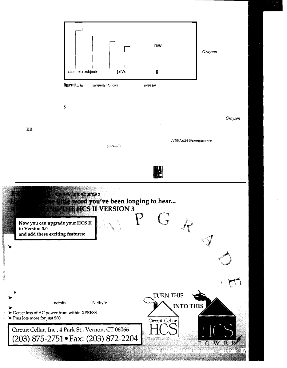
IF context implemented then...
IF object implemented in context then...
IF method supported then...
IF IV used and
checks then
perform method on IV using arguments
<method>
[D <arguments>
CAL
specific parsing
incoming message.
the interpreter. In either
case, execution timing
requirements must be
carefully watched. The
CAL interpreter must
keep up with incoming
messages. Application
routines need to keep up
with changing IV values
and application require-
ments.
Very simple CAL
interpreters, capable of
only minimal require-
ments, have been written for small
microcontrollers in less than KB of
code. A full CAL interpreter, capable
of executing the majority of parsing
and reporting requirements, requires
15-20
TWO DOWN, YOUR ONE
TO GO
The advantage of CAL is that it
knows through context data structures
how residential consumer products
operate. This makes building home
automation systems, software, and
things for devices to do
which are available to the
consumer at reasonable
cost).”
Evans has been
actively involved in home
automation and commu-
nication network
development for the past
14 years. He currently
runs The Training
compliant products possible.
In doing this,
the CEBus protocol and physical layer
specification solves the first required
transition step by providing “a standardized,
physical interface between devices in the
home so information can be easily and
reliably exchanged.”
CAL also solves the second required
transitional
standardized way for
devices to interoperate and talk to each other
using a common language.”
It’s up to you to complete the
third requirement-“a wealth of
truly beneficial applications (i.e.,
Department, which
specializes in CEBus and
related home automation training, and is a
technical consultant to the EIA for the
development of the CEBus and other
consumer electronics standards.
is
also founder and president of Archinetics
Inc., a manufacturer of complete home
automation systems. He may be reached at
corn.
I R S
416 Very Useful
417 Moderately Useful
418 Not Useful
New HCS/PC Interface
l
Query and override any system input, output, or parameter from the PC
l
Revamped HOST Program
l
Use a mouse to resize, move, open, and close all HOST windows
l
Send messages from XPRESS to a HOST window for debugging
l
Set or clear system inputs, outputs, or X-10 modules and try out speech strings from HOST
l
Modem Support
l
Call your HCS from a remote location and check its status, load a new XPRESS program, or retrieve logged data
l
Caller ID
Access Caller ID data from XPRESS to announce or log who‘s calling
Support for more digital I/O expansion boards
l
Read and write eight
at a time with
Send messages to network modules directly from XPRESS
needed a human
interface to my
home-brew
automation system.
This interface had
to be simple, good
looking, and fully
programmable.
Since my home control system is
based on a PC, I could have used
monitor and keyboard, but I didn’t
like the PC’s bulkiness and wanted
the option of multiple interfaces.
My other choices included dumb
terminals (too big and ugly),
shelf terminals (expensive), or a
home-made display terminal (perfect
in all aspects, except my time).
Build my own? A great idea! I
decided to call it
REQUIREMENTS
Once I decided to design my own
display terminal, a list of features
soon appeared:
l
LCD display for text display
l
8 buttons for user input
l
8
for system status
l
attractive enclosure-wall or table
mount
l
875 1 based (easy to wire-wrap)
l
powered from PC.
Since the most flexible display
terminal would use an RS-232
interface to the PC, the buttons and
display would then appear as a dumb
terminal interface. The buttons
generate the ASCII numerals 1-8 and
text from the PC is displayed on the
LCD display. Escape codes access
LCD features and
DISPLAY-S HARDWARE
Figure shows the schematic for
the Display-8 terminal. Display-8 is
based on an Intel 875 1
because
the internal RAM
simplifies wire-wrapping. With the
875 I can use all four I/O ports as I
wish: port 0 reads the key switches,
port 1 interfaces to the LCD display,
port 2 controls the
and port 3
performs various control functions. I
also have a large amount of code
already written for this processor,
which should save me some time.
Add a Human Interface to
Your Home Automation
System
The
are controlled by software
writes to port 2. The switches are
by multiple software reads from port 0.
Display-8 includes a Hitachi
2-line
x
16-character display. Typically, you
would use decode logic to have the
appear as external data space. However,
since I have ample pins on the 875 and do
not enjoy wire-wrapping, I connected the
directly to the processor. Software
controls the pins directly.
The
data bus is connected to
port of the 875 1. The
select pin is tied to P3.4
the read/write
pin is tied to P3.6 (WR), and the enable pin
is tied to P3.7 (RD).
A MAX232 transceiver from Maxim
provides the RS-232 interface. This chip
internally generates the V needed for
RS-232 and requires only four capacitors.
Display-8 uses the 875
built-in serial port
on pins
(RXD) and
(TXD).
Connector is an RJ-11 connector
through which power is supplied and serial
communications take place.
For Display-8, I used C&K switches
that include a DPDT switch and LED in one
housing. The switch fits into a standard
pin socket footprint. Everything is easily
wire-wrapped onto a single protoboard.
Photo 1 shows the component placement.
DISPLAY-S ENCLOSURE
The most important issue of this display
was that it needed to be attractive. I used a
premade aluminum enclosure from
Radio Shack, so I was able to drill
and cut holes for the display and
While many home control systems
operate passively in the
background, users
like some
hands-on interaction with the
system. Display-8 offers that
interaction in a small, unobtrusive
package.
HOME AUTOMATION
CONTROL JULY 1995
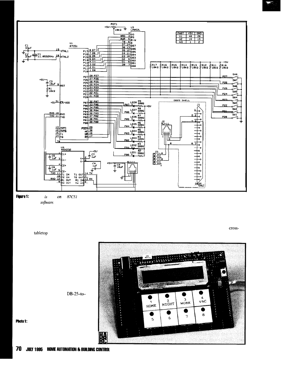
II
I’
RX
TX
Display-8 based
the
microcontroller
for simple assembly. The switch, LED, and LCD hardware decoding is performed by the
microcontroller
key switches. (If you implement this idea,
remember to make your package safe by
filing the cut edges.)
For a
unit, the enclosure comes
with rubber feet and the cable exits in the
rear. My unit is wall mounted and includes a
cutout so it can be mounted over a standard
electrical box. I painted the finished display
white to match the decor of the house.
PC CONNECTION
Since this display is powered from the
PC, I used an adapter cable at the PC to
combine the serial interface and the power
supply (see Figure 1). I used a
RJ-11 converter and a disk drive power
supply extension cable from Radio Shack.
IC sockets protect the components during
assembly. The resistors are located under the LCD
display. Once placed in its enclosure, Display-8 is
ready for table or wall mounting.
DISPLAY-8 SOFTWARE
but more importantly, the 128 bytes of
The more complicated issue was the
data space. For simplicity, I chose to
875 1 software. I wanted to be sure the
use the Archimedes 805 1 C
program fit into the 4 KB of program space,
development tools. This choice
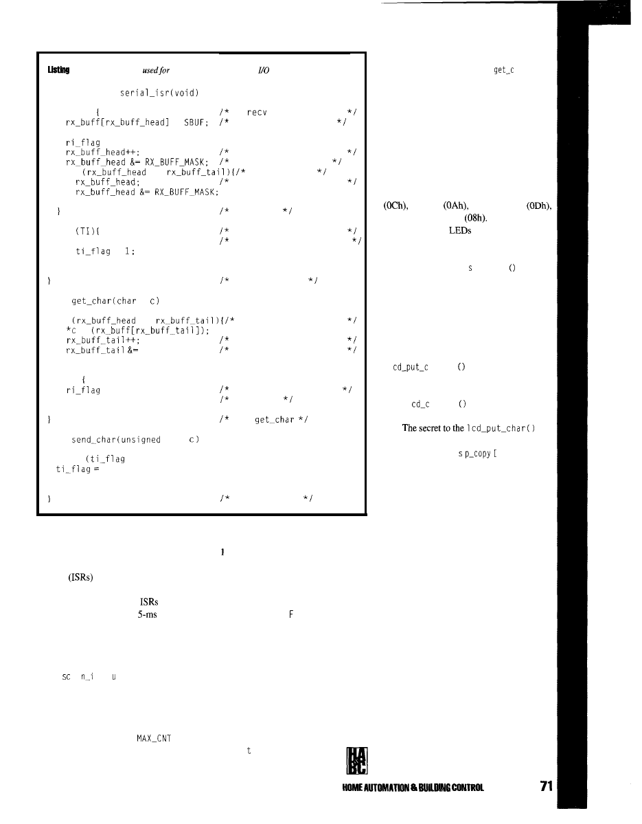
1: Interrupts are only
input with the 8031 serial
routines.
interrupt void
if (RI)
If
interrupt then
=
store char in buffer
RI = 0;
= 1;
increment head pointer
Wrap around the end
if
==
If at tail,
drop character instead
if
TI = 0;
=
end if
RI
If xmit interrupt then
tell foreground routine
return;
char
*
end serial_isr
if
!=
check for empty buf
=
increment tail pointer
RX-BUFF-MASK;
wrap-around if needed
return TRUE:
else
= 0:
return FALSE:
empty buf, clear flag
and fail.
end
void
char
while
== 0);
0;
SBUF = c;
return:
end send-byte
worked out very nicely in that I did
both the serial port and the
timer
tick. The timer ISR simply sets a
global flag that is checked by the
not have to do any assembly language
main routine. The main routine calls
programming. All interrupt service
scan-input
when the timer flag is
set. The
a
n p t
routine first
routines
and output routines
reads the current state of the input
pins and stores the current states in an
were written in C.
array of characters.
The software includes
for
has been received, S
B U
is read and stored in
pressed and a character is sent to the host. A
a circular buffer and the head (input) pointer
is incremented.
hex 3 is added to the switch number (cn t)
to indicate an ASCII 1-8.
The serial ISR is not as simple. Listing
1 shows the serial port routines. The serial
ISR first checks the RI flag. If a character
The OR function checks for wrap
around. If the head pointer is equal to the tail
pointer, the buffer has overflowed. In this
case, the head pointer is decremented, and
the last character is lost. The ISR sets
r i _f 1 a g
to indicate that a new character is
in the input buffer. If the serial ISR detects a
The routine then integrates the
input values for a count of
(three reads or 30 ms). If the inte-
grated input state is 0, then a button is
transmit interrupt, the output buffer
is available and
i _f 1 a g
is set for
the foreground routine.
The main routine checks the variable
r i _f 1 a g
and calls the routine
h a r
to
get the character from the serial buffer. This
routine checks that the head pointer does
not equal the tail pointer. The character is
read from the address of the tail pointer,
and the tail pointer is incremented. If the
tail pointer equals the head pointer, the
buffer is empty and the
r i _f 1 a g
variable is
cleared.
The software in Display-8 supports
several control characters including formfeed
new line
carriage return
and backspace/delete
Also, escape
codes control the
and the special
functions of the LCD driver.
Listing 2 shows the routines involved in
character output. The
d i p 1 a y
routine is
called for each character that is received.
Based on the last character received
(possibly an escape code), the correct action
is taken. If an escape code is received, a flag
is set and the routine returns while waiting
on the next character.
The normal characters are sent to the
1
h a r
function, which controls
the LCD. This function looks for control
characters and sends characters to the LCD
using
1
h a r
and control commands
using
lcd_controlO.
routine is to keep a copy of the display in
memory (variable
d i
1).
The LCD
controller has memory for a 2
x
40 display,
but I am using only a 2
x
16 display. The
software only stores an image of the 2 x 16
memory.
Also, the position of the cursor (row
and column) is tracked by the global
variables
row
and co
1.
If a new line is
found, the cursor advances to the next line. If
it is already on the second line, the second
line is copied to the first line, and the cursor
is positioned at the start of the second line.
After each character is sent to the
display, the position is incremented and
checked for a wrap-around condition. When
a wrap-around condition occurs, the cursor is
repositioned, and the second line is copied to
the first if necessary.
A formfeed character executes a display
home command that clears the display and
positions the cursor in the first position. A
b a c k s pa c e
command repositions the cursor
back one space, prints a blank, and reposi-
tions the cursor again. A carriage return
simply repositions the cursor at the begin-
ning of the current row.
JULY 1985
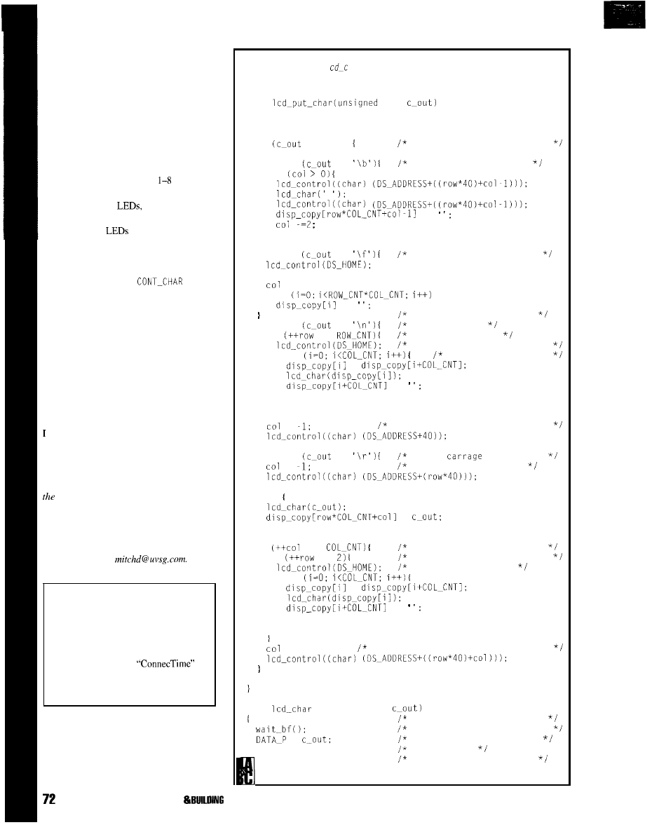
OPERATION
When plugged into a PC, Display-8 can
be used with any communications program.
Characters sent to Display-8 are echoed (so
you can see what you’re typing). Consult the
LCD data manual for a complete list of the
characters available. Carriage return, new
line, formfeed, and backspace characters are
all supported by Display-%
When buttons on the Display-S are
pressed, the ASCII characters
are sent to
the PC communications program.
To control the
send an
LED_
CHAR
command (hex OE, dec 14) and then a
bitmap of which
to turn on. LED 1
corresponds to the least-sigficant bit of the
byte.
Other special functions of the LCD can
be executed by issuing a
command (hex OF, dec 1.5) and then the LCD
control byte. This byte is written to the
control register of the LCD display.
Graphics characters can also be defined
in this way. Data read-back capabilities of
the LCD display are not available to the
serial port user.
FINALE
Display-8 provides an excellent user
interface to my home control system. In fact,
like the design so much that I am planning
on building more units to use around for
other control functions.
Mitch Drummond is a design engineer for
cable television industry. Mitch has been
developing embedded systems for military
and commercial applications for over ten
years. He’s currently developing a home
automation system in his spare time. Mitch
may be reached at
SOFTWARE
Software for this project is available
from the Circuit Cellar BBS and on
Software On Disk for this issue.
Please see the end of
in this issue for downloading and
ordering information.
I R S
419 Very Useful
420 Moderately Useful
421 Not Useful
JULY 1995 HOME AUTOMATION
Listing 2:
The
function 1
ha r controls the
LCD’s I/O
pins for writing data to the
display.
void
char
int i:
if
== '\a')
No bell on display, ignore.
else if
==
backspace, delete char.
if
=
else if
==
formfeed, so clear screen
row = 0;
= -1;
for
=
new line. If on 2nd row,
else if
==
copy to first.
if
==
Clear the display
copy 2nd row to 1st row and
for
clear 2nd row memory
=
=
row = 1;
=
put cursor at start of 2nd row.
else if
==
Insert
return, put
=
cursor at first column
else
=
if
==
inc ptr; process next char
if
==
copy 2nd row to 1st row and
clear 2nd row memory
for
=
=
row = 1;
= 0;
reposistion cursor in correct place
return;
void
(unsigned char
Write character to display
wait for the LCD ready flag
=
place the data on the bus
RW = WRITE:
set to write
RS = DATA:
select the data register
(continued)
CONTROL
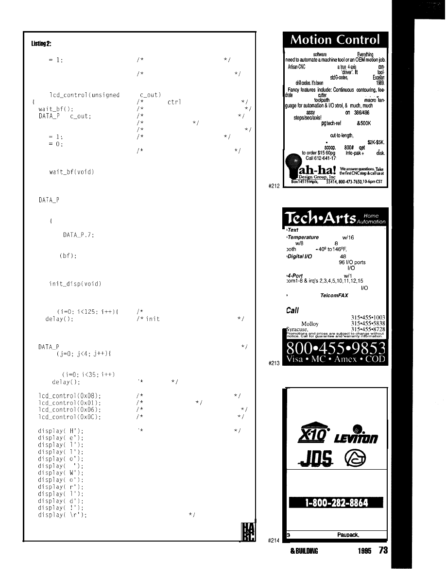
continued
E
E =O;
return:
pulse the enable line
return, assume it worked
void
char
Write
byte to display
wait for the LCD ready flag
=
place the data on the bus
RW = WRITE:
set to write
RS = CONTROL:
select the control register
E
pulse the enable line
E
return:
return, assume it worked
void
char bf;
= Oxff:
RS = CONTROL:
RW = READ:
do
E = 1;
bf =
E = 0;
while
return;
void
char i, j;
for
wait for power to settle and*/
display. Pause 15 ms
RS = CONTROL:
RW = WRITE:
= 0x38;
for
E = 1;
E = 0;
for
'* 8 bit, 2 lines. 5 x 7 font
4.1 ms
display/cursor/blink off
clear display
increment dd ram, no shift
disp on, cursor/blink off
return:
Just a test for the PROM
* return home
From the
to the motor shaft!
you
software is
machine
troller w/user interface, not just a
takes
path files
in industry
HPGL, or
PCB
refined&updated
since
override.
radius mmoensation.
bio 1’
screen read&,
graphics:
PLC
more.
Very fast
language runs a
VGA to
40K
Indexer-l/O card for ISA bus in-
cluded in prii. 130
manual
Help.
Make a PCB drill, CNC a Mill in your shop, or use as
OEM for machine tools,
labeling, etc..
Software from $349
$849. Systems from
Call us for the whole
Use
to catalog or
Tech
demo
97 for a sales engineer.
6 1 2 - 6 4 1 - 1 7 9 7
MN
to Speech Board
serial I/O
$ 8 9
boards:
sensors $239
sensors plus analog inputs
$179
boards:
serial I/O
ISA cards:
I/O ports
$125
$ 1 6 9
192
ports $249
ISA Serial Board
6550s
$129
J-Servo controller board
serial
$ 8 9
Windows NT
Personal
$129
-Automatic Drapery Controller
$ 1 3 9
for our complete catalog!
support
308 E.
Rd
Fax
NY 13211
BBS
Home
Automation
Worthington
Distribution
NO MINIMUMS
NO HANDLING FEES
TRUE DEALER PRICING
6 Gumbfetown Road.
PA 18451
HOME AUTOMATION
CONTROL JULY

ARTMENTS
Firmware Furnace
From the Bench
Silicon Update
Embedded Techniques
Ed Nisley
Journey to the Protected Land:
The Mystery of Scan
Code Set 3
looked at one of
your old projects and
asked, “Who wrote this
ave you ever
code and what was I thinking?” I know
I have! Sometimes you can replace a
page of tortured logic with a single,
obvious, crystal-clear function..
is, until you look at it again in a few
years.
Last month, you saw how the PC’s
keyboard evolved from a fairly simple
subsystem into a complex mess. Each
change made sense at the time, but the
end result is essentially incomprehen-
sible. Imagine designing a system that
produces eight bytes for a single key.
This month, 1’11 examine the
keyboard hardware and firmware built
into every PC. Protected mode gives us
the opportunity to switch the key-
board’s fundamental operation into
something sensible. As you’ll see,
talking to the keyboard exercises some
interesting machinery.
Crystal clear? Check it again next
year!
CONTROLLING THE
CONTROLLER
The keyboard controller on the
system board is an 8042 Universal
Peripheral Interface, also known as a
microcontroller. It’s generally easy to
spot since a 40-pin DIP looks terribly
out of place on a system board where
74
Issue
July 1995
Circuit Cellar INK
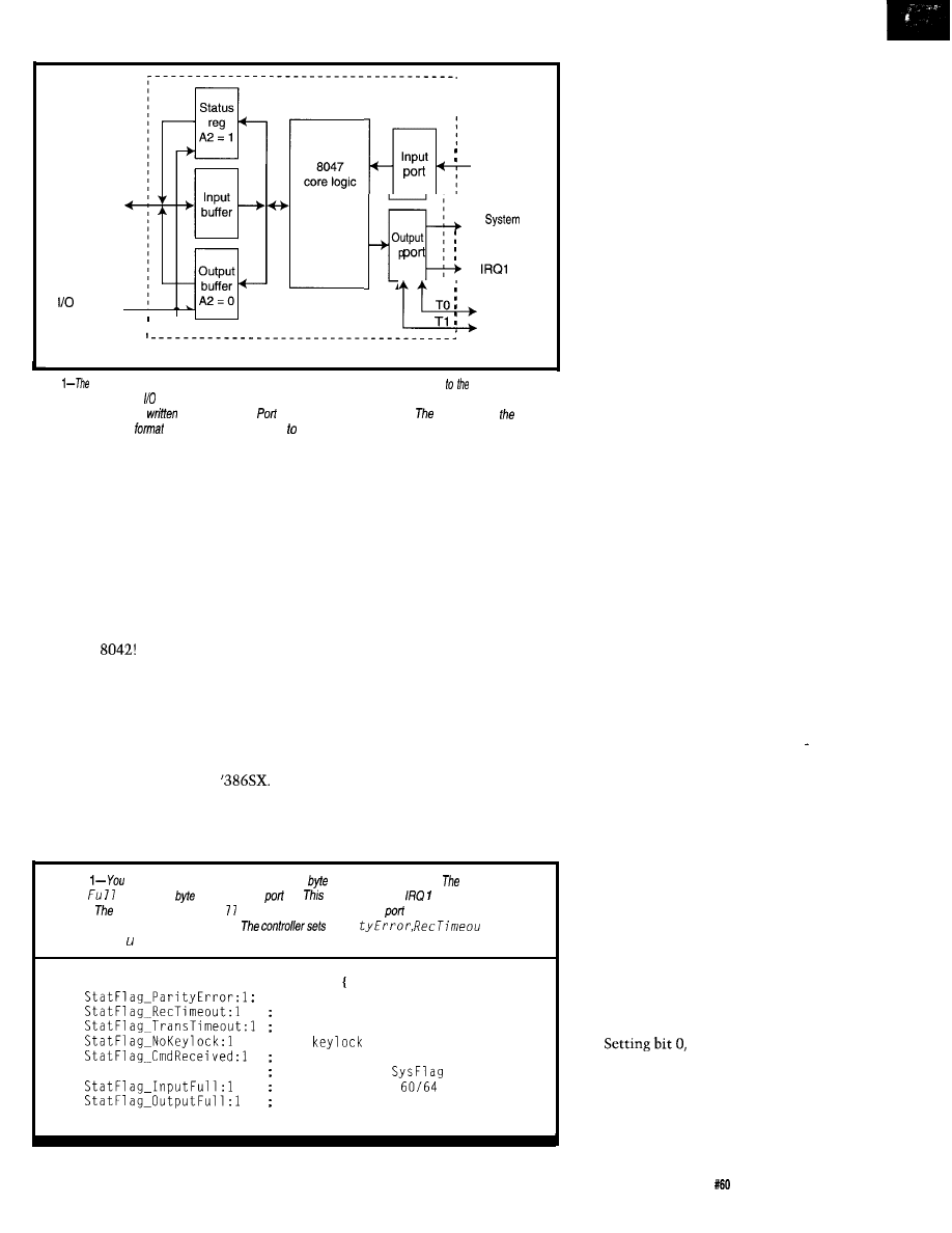
System
data bus
address
bit A2
Input
System
status
output
controls
TO
Keyboard
8042 Universal Peripheral Interface
Figure
system
board keyboard controller is an 8042 microcontroller interfaced main CPU through a
pair of byte-wide ports at addresses 60 and 64. Port 64 sends commands to the controller and returns status
bits; the values read and
are not identical.
60 is a bidirectional data port.
8042 hand/es
keyboard’s serial data
and serves as an interface the system board’s status and control bits.
three or four surface-mount LSI parts
hold several million logic transistors.
Current systems sport genetically
engineered 8042 descendants stuffed
with specialized speed-up hardware.
A great deal of weirdness sur-
rounding the keyboard controller goes
away as you read the Intel 8042 data
sheet. Figure 1 sketches the key
features. As you can see, all the logic is
inside the
The main system’s
only access is through two I/O ports at
addresses 60 and 64 (hex) and the
output driving IRQ 1.
hardware flags shown in Listing 1.
Internal hardwired logic sets Status
Register bit 0, the OBF flag, when the
8042 firmware writes a byte into the
Output Buffer and clears it when the
‘386SX reads the byte.
Reading port 60 selects the 8042
Output Buffer through which the
controller sends keyboard scan codes
and other information to the
Reading port 64 selects the 8042 Status
Register, which contains the five
firmware-controlled bits and three
The 8042 firmware controls an
internal gate that routes OBF to the
pin driving IRQ 1. Each time the
firmware writes a byte into the Output
Buffer, IRQ 1 goes high and the ‘386SX
CPU executes the IRQ 1 interrupt
handler. You can enable and disable
this interrupt in three places: the 8042,
the 8259, and the CPU’s Interrupt Flag.
Writing a byte to either port 60 or
port 64 loads the 8042 Input Buffer and
sets Status Register bit 1, the IBF flag.
Hardwired logic also copies I/O
address bit 2 into Status Register bit 3
on each write, giving the firmware an
Listing
may read the keyboard controller status
from port 64 at any time.
8042 sets
Output
whenever a
is available at
60.
flag also triggers
if interrupts are
enabled.
hardware sets Input Fu
immediately after each write to
60 or 64, indicating that the
firmware has notyetprocessed the byte.
Par i
t, and
Tr a n s Time o t after performing several retries on its own.
RECORD
STATFLAGS
kbd serial parity error
timeout during kbd message
timeout after ctl message
; 0 =
switch ON
1 = last write to Port 64
StatFlag_SysFlag:l
keyboard OK or
= 1
1 = no write to
1 = read data from 60
easy way to
distinguish the two
sources. IBF goes low when the 8042
firmware reads the Input Buffer.
The keyboard controller firmware
accepts data through port 60 and com-
mands through port 64. Although the
‘386SX CPU writes to two separate
ports, they neck down to a single
chunk of 8042 hardware. You must
verify that IBF is low before writing to
either port, lest you overwrite a previ-
ous value before the 8042 has read it.
With that hardware background in
mind, the keyboard controller should
make more sense. The 8042 firmware
recognizes about 120 commands
written to port 64, most of which are
entirely irrelevant for normal opera-
tion. Listing 2 shows the few com-
mands used by the FFTS keyboard
interface.
The terminology doesn’t help
much. The ‘386SX writes these
commands to port 64. One of the
commands, 60 hex, is Write Com-
mand Byte. The Command Byte,
shown in Listing 3, is subsequently
written to port 60. The only way to get
familiar with this stuff is to use it.
Bit 6 of the Command Byte,
T r a n s 1 ate,
determines whether the
controller translates raw keyboard
scan codes into system scan codes.
This bit is normally on because the
keyboard defaults to Scan Code Set 2,
the baroque multibyte scheme I
described last month. When
T r a n s
1 ate is
zero, the controller passes the
keyboard’s scan codes directly to port
60 without modification. As I’ll
discuss later, turning this bit off is
essential for the FFTS interface.
Whenbit4,
DisableKbd,ison,
the
8042
firmware forces the keyboard
clock line low to prevent the keyboard
from sending anything to the control-
ler. Normally, your set-up routine
turns this bit on and your operating
code uses the Enable and Disable
Keyboard commands to flip the bit,
thus eliminating the need to write a
new Command Byte.
EnableInt,on
enables the IRQ 1 interrupt whenever
the OBF bit goes on. The hardware
doesn’t care why the Output Buffer
became full; OBF goes on whenever
the 8042 firmware writes a byte
Circuit Cellar INK
Issue
July 1995
75
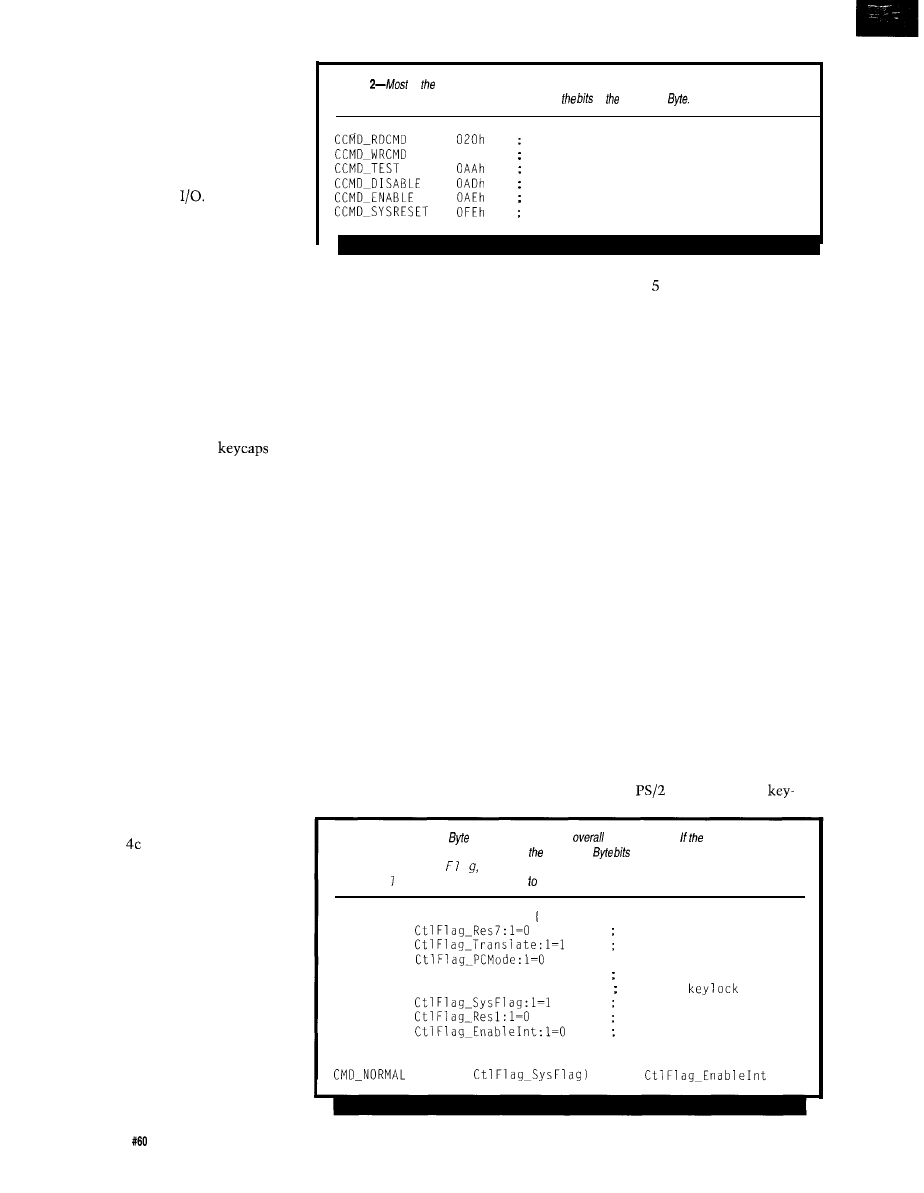
whether it’s a scan code or a response
to a command. You must ensure that
your keyboard interrupt handler is
never surprised by a byte that isn’t a
keyboard scan code.
The three routines shown in
Listing 4 handle low-level system
keyboard controller
I have
omitted statements that generate the
tracing and debugging messages you’ll
see later.
KEYBOARD CONVERSATIONS
Notwithstanding the preceding
discussion, the system keyboard
controller’s main purpose in life is
converting between keyboard serial
data and PC parallel data. Generally,
our code talks directly through the
keyboard controller to the keyboard
itself, so we must know what the
microcontroller under the
expects to hear.
Unless the system keyboard
controller is busy processing a com-
mand written to port 64, it simply
passes data written to port 60 directly
to the keyboard in serial form. The IBF
flag indicates that the data previously
written to either port 60 or 64 hasn’t
been processed yet. Listing 4b takes
care of this with the same code that
writes data to the Input Buffer after a
system-keyboard-controller command.
Similarly, the controller converts
any data arriving from the keyboard to
parallel form and places it in the Out-
put Buffer register, triggering IRQ 1 if
interrupts are enabled. Reading port 60
extracts the data, resets OBF, and
clears IRQ 1. The controller disables
the keyboard while OBF is set, elimi-
nating the possibility of an overrun.
Listing reads Output Buffer
bytes without regard to where they
came from and thus returns bytes from
the keyboard as well as the system
keyboard controller. This code is
useful only after commands producing
a response byte because the normal
keyboard scan codes should go to the
IRQ 1 interrupt handler.
Serial data flows between the
system keyboard controller and the
keyboard at a peak rate of about 10
kbps (see Photo 1, FF,
INK 59).
The
average data rate is much lower,
limited mainly by delays between the
76
Issue
July 1995
Circuit Cellar INK
Listing
of keyboard
controller commands are not useful during normal operation. The FFTS
routines use fhese few commands. Listing 3 shows
in
Command
=
read controller command
= 060h
write controller command
=
test controller
=
disable keyboard
=
enable keyboard
=
reset the entire system!
bytes-even the fastest typists have
trouble generating a few hundred
keystrokes per second. I’d say the link
is fast enough.
The communications protocol’s
details aren’t of much use to us right
now. Suffice it to say that when the
system keyboard controller lowers the
clock line, the keyboard cannot
transmit information and stores
keystrokes in its internal buffer. You
must disable the keyboard using the
system keyboard controller Disable
Keyboard command (AD hex) before
issuing any commands using the Input
or Output Buffers. If the keyboard
remains enabled, it may send a byte
that arrives just after your command
and confuse the proceedings.
Listing shows how to send a
byte to the keyboard and process the
acknowledgment. I suspect the only
proper response to an error that makes
it past the system keyboard
controller’s retries is “Your keyboard
just died.” In this routine, I simply
ignore persistent errors and continue
without complaint.
The keyboard recognizes about a
dozen commands, many of which
aren’t relevant to our purposes. Listing
6 shows the few we’ll need for the
FFTS routines.
Now onto the fun part!
CONVERTING THE CODES
The keyboard sends an acknowl-
edgment for every byte it receives from
the system. If the byte had good parity
and timing the keyboard sends FA hex
(pronounced “Ack”). Most errors
results in FE hex [say “Error”). Merci-
fully, the system keyboard controller
handles error conditions by resending
the byte several times before setting
the Status Register error bits.
The complexity of deciphering all
the scan codes produced in all the shift
states for all the keys seemed too
daunting when I first looked into this
topic. Frankly, writing a replacement
BIOS keyboard handler wasn’t some-
thing
I
wanted to tackle!
When faced with an impossible
situation, sometimes you can restate
the problem so the solution is obvious.
In this case, a light went on when I
read that
and some other
Listing
3-This Command
defines fhe controller’s
operating mode. system includes a F’S/
P-style system-board mouse port, several of Command
have different meanings. The B/OS
sets Tr a n s 1 a t e, Sys
a and En a b 1 e In t affer each system reset. The FFTS keyboard routine
turns Jr an s a t e off to gain direct access the keyboard’s scan codes.
RECORD CTLFLAGS
reserved, must be 0
translate AT to PC
; use
PC serial intf
CtlFlag_DisableKbd:l=O
force kbd clock low
CtlFlag_DisableInhibit:l=O override
1 after BIOS setup
reserved, must be 0
enable IRQ 1 interrupt
= (MASK
+ MASK
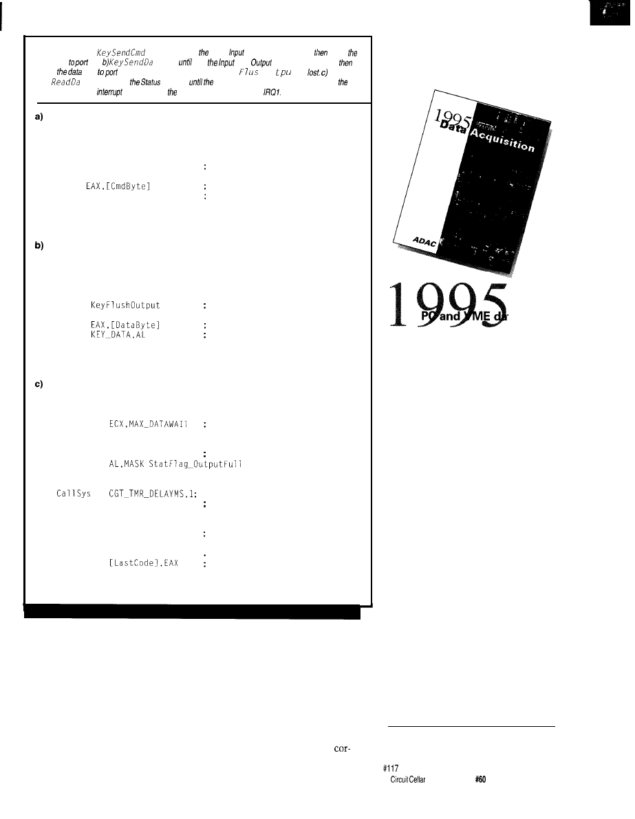
Listing 4-a) The
routine waifs until 8042
Buffer Full flag is clear,
writes
command
64.
ta waifs
both
and
Buffer flags are c/ear,
writes
byfe
60. Any scan codes arriving before Key h Ou t are
The
Key
t a routine polls
Register
Output Buffer flag goes high, then reads
byte. The keyboard
handler snags byte firsf unless you disable
PROC
ARG
USES
CALL KeyWaitInBuff
MOV
OUT
RET
ENDP
PROC
ARG
USES
CALL
KeyWaitInBuff
CALL
MOV
OUT
RET
ENDP
KeySendCmd
CmdByte:DWORD
EAX
KEY_CMD,AL
KeySendCmd
KeySendData
DataByte:DWORD
EAX,ECX
PROC
USES
MOV
@Stall:
IN
TEST
JNZ
LOOP
@Fetch:
IN
Punt
MOVZX
MOV
RET
ENDP
KeySendData
KeyReadData
ECX
AL,KEY_STATUS
wait for prev cmd to finish
fetch the command
send it out
; wait for cmd to clear
discard any pending bytes
fetch the data
send it out
maximum delay
key ready yet?
@Fetch
nope, wait a bit
@@Stall
and try again
AL,KEY_DATA
fetch the data
EAX,AL
clean up the byte
and save for examination
KeyReadData
boards supported three scan-code sets,
one of which produced a single byte
per keystroke. I knew a bit about why
Scan Code Set
3
existed, a tale told
here last month. The only remaining
question was how many clone key-
boards supported that feature.
Rick Freeman and the folks at
Computer Options here in Raleigh
graciously loaned me one of every
keyboard in the store. Adding those to
my ragtag collection, I checked out a
dozen Enhanced keyboards and found
that, with a single exception, they all
supported Scan Code Set 3. The
oddball, a Northgate C/T keyboard,
dates back to 1988 when Enhanced
keyboards were very, very new.
While that’s not conclusive proof
that all PC keyboards respond
FREE
Data Acquisition
Catalog
ta
acquisition catalog
from the inventors of
plug-in data acquisition.
Featuring new low-cost
A/D boards optimized
for Windows,
DSP Data Acquisition,
and the latest
Windows software.
Plus, informative
technical tips and
application notes.
Call for your free copy
l-800-648-6589
ADAC
American Data Acquisition Corporation
70 Tower Office Park, Woburn, MA 01801
phone 617-935-3200 fax 617-938-6553
INK
issue
July 1995
7 7
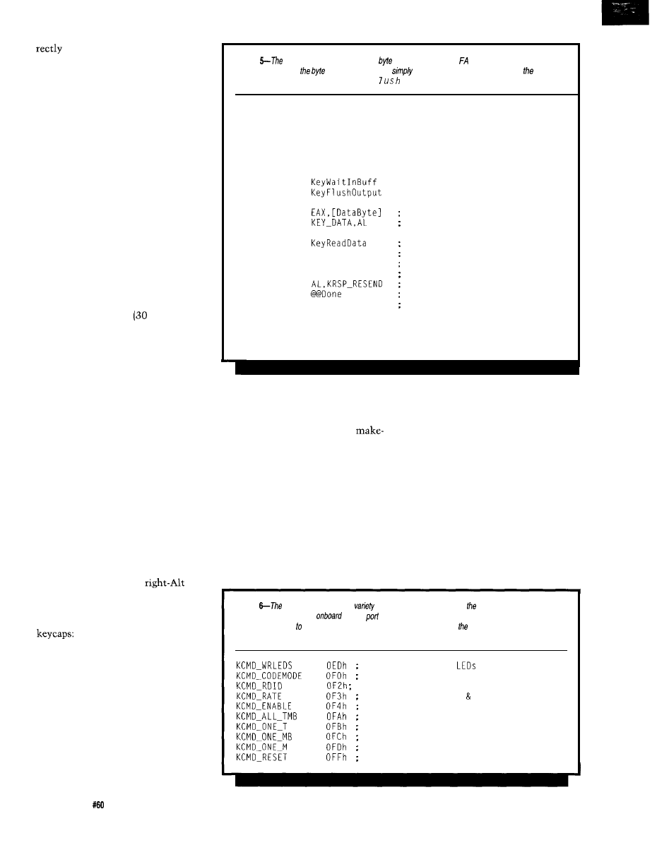
to the code in FFTS, it gave me
enough confidence to try this trick.
I’m interested in hearing how this
works out on your system. But, if your
keyboard doesn’t support Scan Code
Set 3, you get to decode its output.
I
want no part of Scan Code Set 2, thank
you very much.
The code in Listing 7 handles the
transition from the BIOS default
keyboard settings to the new condi-
tions. It runs the self-test routines in
the system keyboard controller, and
the keyboard then sends several
commands to the keyboard. If any of
the first few commands fail because of
a missing keyboard or missing feature,
the keyboard is disabled and unusable
in FFTS.
I always set my keyboards for the
shortest typematic delay (250 ms) and
the fastest repeat rate
characters
per second). Recognizing that your
reflexes may vary, I’ve declared a group
of constants that go all the way to
stun: two characters per second after a
one second delay.
Scan Code Sets 1 and 2 automati-
cally set all keys to typematic-make-
break mode, leaving the BIOS to sort
out the superfluous make codes. Scan
Code Set 3 works differently, placing
only the typewriter and cursor keys in
typematic mode. Most of the remain-
der are make-only keys that send a
single code when they’re pressed, do
not repeat no matter how long they’re
down, and do not send a break code
when they’re released.
Most of the shift keys operate in
make-break fashion, sending only a
single make code and a single break
code. Oddly enough, the
and
right-Ctrl keys are make-only, which
is sensible when you see the main-
frame and minicomputer keyboard
one is an Enter key and the
other does something similar. Remem-
ber, PCs aren’t the only computers in
the world!
The good news is that you can
reprogram the key modes to suit your
needs. A single command sets all the
keys to the familiar typematic-make-
break mode used in the other Scan
Code Sets. This mode is appropriate
for typewriter keys, cursor keys, and a
few others, eliminating the need to
78
Issue
July 1995
Circuit Cellar INK
Listing
keyboard
acknowledges each
if receives with either hex (good) or FE hex (error).
This routine resends
a few times and then
ignores the error. You must disable
keyboard
before calling this routine to ensure that Key F
Ou
tpu t doesn’t inadvertent/y discard a keystroke.
PROC
KeySendDataAck
ARG
DataByte:DWORD
USES
ECX
MOV
ECX,MAX_RETRIES
@Resend:
CALL
CALL
retry counter
wait for cmd to clear
discard any pending bytes
MOV
fetch the data
OUT
send it out
CALL
fetch byte
MOVZX EAX,AL
clean it up
CMP
AL,KRSP_ACK
ack?
JE
@ D o n e
yes, done
CMP
resend?
JNE
no. ignore it
LOOP
@Resend
yes, try again
@@Done:
RET
ENDP
KeySendDataAck
reprogram each and every key indi-
is no need to process and discard
vidually.
additional make codes.
Three additional commands set
individual keys to make-only,
break-only, or typematic-only mode.
The key’s make scan code follows the
command byte, which means you
must program each key individually.
The keyboard accepts these commands
when any Scan Code Set is active, but
they apply only to Scan Code Set 3.
The most useful function keys in
make-only mode are Esc, Ins, Home,
and End. These keys produce a single
scan code that triggers a single action.
Again, not having to deal with re-
peated keys simplifies programming.
Some applications can probably
take advantage of typematic-only
function keys that send repeated make
codes with no break code at the end.
All the FFTS definitions reside in a
table, making it easy to contort the
keyboard to suit your needs.
The make-break mode is a natural
for shift and lock keys as the make
code indicates that the key is down
and the break code says it’s up. There
Listing
keyboard responds to a
of
commands sent through system keyboard controller.
Some systems include an
mouse
driven by the system keyboard controller; the mouse
controller responds a slightly different command set. This list includes most useful keyboard
commands.
=
write to keyboard
=
get/set scan code mode
=
read keyboard ID
=
set typematic delay rate
=
enable keyboard
=
all keys typematic/make/break
=
set single key to typematic
=
set single key to make-break
=
set single key to make-only
=
reset to power-on defaults
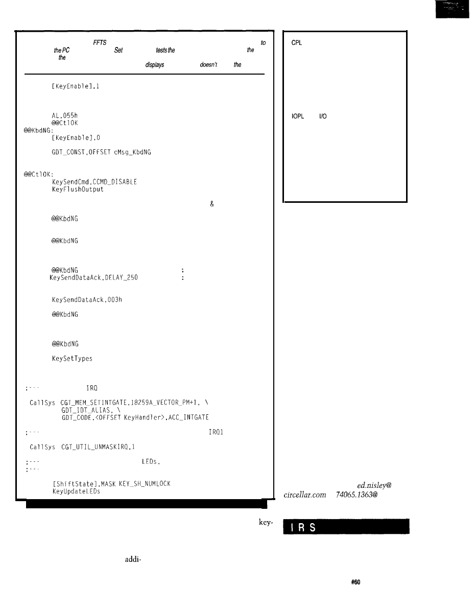
Listing
I-The protected-mode
keyboard interface uses Scan
Code Set 3 because if’s much easier
process than default, Scan Code
2.
This routine
system keyboard controller and
keyboard, sets keyboard’s new operating modes, and prepares the interrupt handler. If the keyboard isn’t
present or doesn’t support Scan Code Set 3, the code
a message and
enable keyboard.
MOV
CALL KeySendCmd,CCMD_TEST
CALL KeyReadData
CMP
JE
MOV
CALL ConfSendString,CON_SERIAL, \
JMP
@@Done
CALL
CALL
assume OK..
test controller
fetch result code
is it OK?
keyboard failure!
disable keyboard
discard pending codes
CALL KeySendDataAck.KCMD_RESET
CMP
AL,KRSP_ACK
JNE
CALL KeyReadData
CMP
AL,OAAh
JNE
CALL KeySendDataAck,KCMD_RATE
CMP
AL,KRSP_ACK
JNE
CALL
+ RATE-30
CALL KeySendDataAck,OFOh
CALL
CMP
AL,KRSP_ACK
JNE
CALL KeySendDataAck,KCMD_ALL_TMB
CMP
AL,KRSP_ACK
JNE
CALL
reset test keyboard
accepted byte?
nope, no keyboard
fetch result code
is it OK?
nope, bad hardware
set typematic rate
did it work?
nope, bad hardware
yup, get smokin'
select scan code...
Set 3
did it work?
all typematiclmlb
did it work?
set individual keys
CALL KeySendDataAck,KCMD_ENABLE
enable key scanning
install the
1 interrupt handler
enable 8259 keyboard controller interrupt on
set numlock on, update the
and (en passant)
enable the keyboard
OR
CALL
Each of the routines called in
tional messages. The self-test and
Listing 7 sends tracing information to
board response delays differ among the
the serial port. If the keyboard can’t
keyboards I’ve tested. I’ve picked
support Scan Code Set 3 or if it reports
default timeouts long enough to handle
a self-test error, you’ll see a few
much worse than the worst I’ve seen.
DPL
EOI
FDB
FFTS
GDT
GDTR
IBF
IDT
IF
LDT
LDTR
NT
OBF
P bit
RF
RPL
TF
TR
TSS
Current Privilege Level
Descriptor Privilege Level
End Of Interrupt (command)
Firmware Development Board
Firmware Furnace Task Switcher
Global Descriptor Table
GDT Register
Input Buffer Full
Interrupt Descriptor Table
Interrupt Flag
Privilege Level
Local Descriptor Table
LDT Register
Nested Task
Output Buffer Full
Present bit (in a PM descriptor)
Resume Flag
Requestor Privilege Level
Trap Flag
Task Register
Task State Segment
The end result of all this is a
sensible keyboard-each key has a
unique, single-byte scan code. We can
surely build something interesting
from that raw material!
RELEASE NOTES
Demo Taskette 3 now displays
doublewords containing the shift state,
system scan code, and character for
each keystroke that produces a
character. The keyboard interface
routines send a torrent of tracing
information to the serial port on each
make and break code, exposing the
inner workings (and perhaps failings)
of your keyboard.
I planned to wrap up the keyboard
this month, but there’s more code than
pages. Next month, we’ll look at the
interrupt handler that queues scan
codes and the translation routines that
convert them into familiar real-mode
BIOS values.
q
Ed Nisley, as Nisley Micro Engineer-
ing,
makes small computers do
amazing things. He’s also a member of
Circuit Cellar INK’s engineering staff.
You may reach him at
or
compuserve.com.
422
Very Useful
423 Moderately Useful
424 Not Useful
Circuit Cellar INK
Issue
July 1995
79

Sacrifice for
the Good
of the Circuit
Strengthening
the Weak
Jeff Bachiochi
was a constant
occurrence. Someone
in an additional appliance and
we’d all be in the dark. I was always
curious why this scenario always
seemed to happen after daylight had
faded into night.
“I must have blown a fuse,” came
the guilty party’s cry.
“Everyone stay where you are,”
my Dad would say in a calming voice.
He knew the routine. The most
difficult part was getting to the
flashlight on the pantry shelf. “1’11 get
the flashlight and have it fixed in a
moment.”
We all cringed at those words. We
knew what would follow: “All right!
Who took the batteries out of the
Matches and candles were more
prevalent back then. I think I now
understand why. Burning candle in
hand, Dad descended the basement
stairs and searched the rows of tiny
windows for the one missing link.
All the fuses looked alike-the
and
could be easily
interchanged. Without the correct
replacement, there was a real tempta-
tion to do just that. But even tempo-
rarily, this was a real fire hazard.
Through the years, manufacturers
improved the safety factor by design-
ing screw-in fuses with different size
bases. At least then, you had to use the
correct size fuse. This also eliminated
using the cheapest fuse replacement:
the one-cent fuse.
Three cheers for the circuit
breaker. Although they incur a much
higher initial cost, replacements are
unnecessary. Even a child can safely
reset a tripped breaker without
exposure to dangerous voltages.
Many electronic appliances today
use protective devices-thermal and
current fuses are the most popular.
They are added to protect the circuitry
against excessive current, voltage, and
temperature. And, like the fuses which
protected our homes, once they do
their job, they must be replaced.
On those appliances with fuse
holders, replacement is easy, although
flashlight?” Luckily, the darkness and
using the incorrect fuse size is still a
our silence made a perfect cover.
problem. On products with fuses
Photo
devices are rapid/y overtaking
fuses on
race circuit
82
Issue July 1995
Circuit Cellar INK
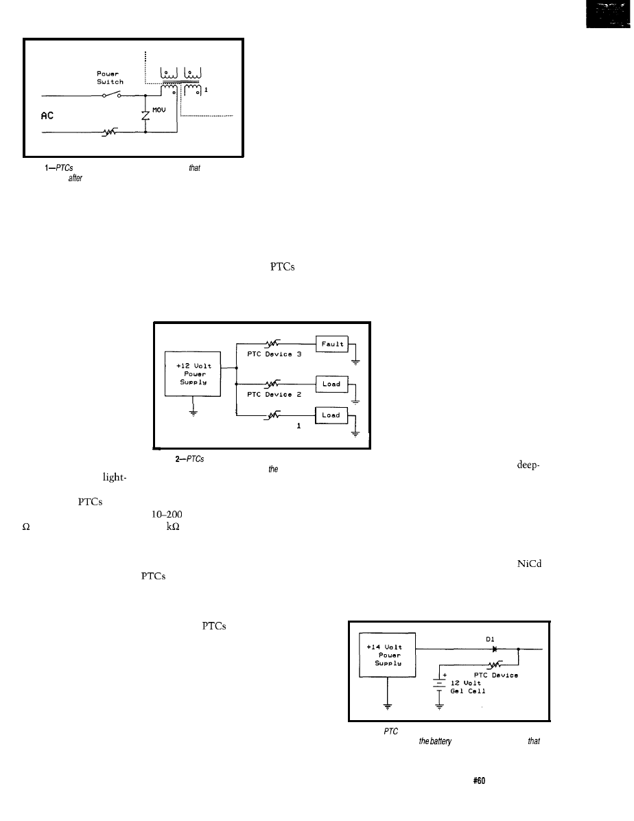
S e c o n d a r i e s
P T C D e v i c e
Figure
can replace fuses as circuit protection
doesn’t
require service
being tripped.
This isolation causes
the rise in resistance
responsible for limiting
current flow to the
circuitry. With a continu-
ing fault, an equilibrium
is established in which
the limited current
produces sufficient heat to
keep the device in its
tripped state. Once the
fault is removed, the
device cools and the
hidden somewhere inside, you’re
polymer returns to its crystalline state.
pretty much out of luck.
The conductive particles once again
PTC [positive temperature
form chains, reducing the device’s
coefficient) devices can change all that.
resistance and allowing full current to
Photo 1 offers a pictorial sample of the
pass though.
PTC takeover of the fuse.
RECOVERABLE CIRCUIT
PROTECTION
These poly
service a much
higher maximum working voltage (up
to 600 V) in a much smaller size.
Initial resistance ranges from a fraction
A PTC device raises its
resistance in response to
rising temperature. This
rise can be due to increased
ambient temperature or
power dissipation within
the device. The physical
bulk of the device acts as a
delay, altering its switch-
ing times. This delay
enables the PTC to be
P T C D e v i c e
Distributed power for sensors and
peripherals can be protected by PTC
devices individually matched to their
respective circuit requirements.
Distributed power, although economi-
cal, causes total system failure even
when the most insignificant part fails.
Complete system failure can be
avoided by protecting each peripheral
independently. The remaining parts of
the system continue operating, even
when a fault exists in part of it. With
the proper feedback, the system is
able to intelligently report the fault
instead of just grinding to a halt (see
Figure 2).
unaffected by inrush, start-
Figure
protect individual secondary circuit branches from one
Backup batteries can be easily
up, surge, and transient
another so a failure in one won’t affect others.
damaged by overcurrent-both
currents including
cycle recharging and having to supply
FIRE AND SECURITY ALARM
SYSTEMS
Underwriters Laboratories
requires any user-replaceable fuses to
be short circuited for fault-current
testing. This ruling requires manufac-
turers to have additional calamity
protection.
Under most circumstances, this
extra protection involves a device
(second fuse or other current-limiting
device) which requires service after a
short-circuit fault condition. A
resettable PTC switch (see Figure 1)
replaces both external and internal
protection, eliminating the need for
component replacement.
ning strikes.
Ceramic
have been around
for years. These devices range
at 25°C and can rise to above 5
at
trip currents. Since the full applied
voltage may appear across the device,
it must be rated for the maximum
potential possible. Ceramic
are
generally limited to 100 V or less.
A new entry to the PTC market
gets its protective abilities from a
specially formulated composite of
plastic and conductive materials. At
normal temperatures, the conductive
particles form low-resistance chains
within the crystalline structure of the
polymer. As current increases, power
dissipation and temperature rises. As
a result, the crystalline structure
breaks into an amorphous mass,
isolating the conductive particles from
one another.
of an ohm to 10 ohms at 25°C and
rises to hundreds or thousands of ohms
in the tripped state.
It is important to note here that,
even in a tripped state, current still
flows through the circuit. However,
this reduced current is far below
normal operating current and is based
on the voltage input and power rating
of the device.
Suggested applications for
include instrumentation
and control, security systems,
medical equipment, batteries,
computers and peripherals,
audiovisual equipment, toys,
telecommunications networks,
modems, and transformers.
Let’s look into a few of
these to see how the PTC
device aids in reducing equip-
ment down time.
Figure 3-A
device limits charging current and short-circuit
load current, protecting
from permanent damage
might otherwise occur
short-circuit currents. PTC switches
interrupt short-circuit currents,
preventing a potential battery explo-
sion. Ultrathin packaging, designed
especially for battery packs, enables
manufacturers to replace the strap
normally welded to the ends of
batteries, creating total protection
within the pack. While able to inter-
rupt currents as high as 100 A, the
Circuit Cellar INK
Issue
July 1995
8 3
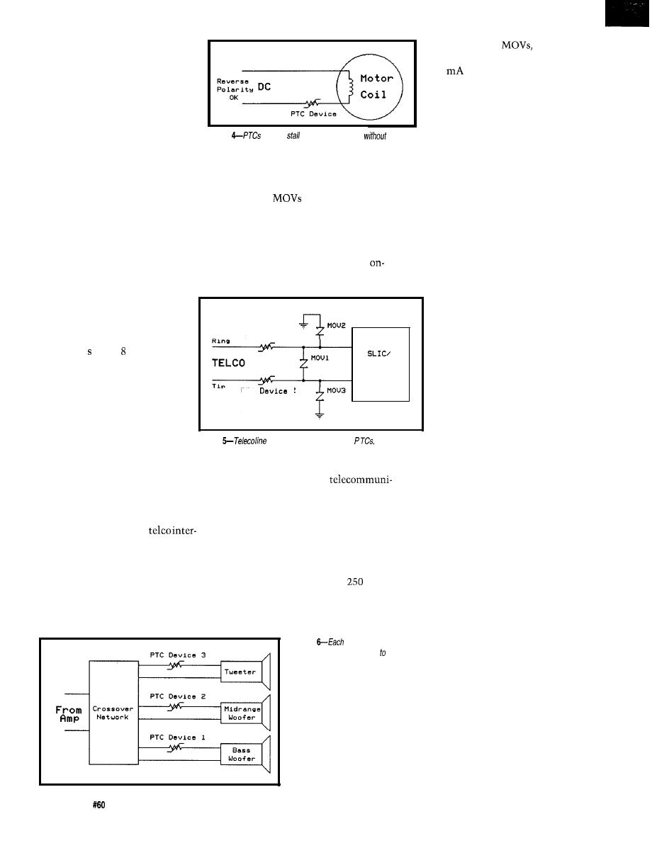
smallest PTC devices trip at under
3 A (see Figure 3).
AUTOMOBILE APPLICATIONS
Figure
provide
protection in motors
need for
fuse replacement
Power windows, door locks,
and wipers all use motor and
solenoid mechanisms. Without
relying on a fuse, a PTC device
limits current to a stalled or
jammed device, preventing
burnout. Stalling or jamming a device
is easy enough to do. It could be
caused by frozen wiper blades, an arm
out the window (usually this results in
needing a protective device for Mom
and Dad’s ears, too), or even closing a
window that’s already up. Individually
protecting each mechanism prevents
one failure from affecting other
circuits sharing the same fuse.
A l-A, 12-V DC motor
might draw 5-10 times that
current when stalled. A PTC
device with a 1-A rating trips in
less than 1 when A are passed
through it.
It is important to note that
wiring must be rated to survive
stalled currents. Otherwise, the
wire’s insulation can become
weakened from overheating or
worse-the harnessing can
become the motor’s fuse.
The PTC devices drawn in
Figure
faults are
current limited by
providing user
distortion or change to the
and circuit protection.
or across the tip and ring pair. Special
protection is necessary.
line once the fault has been corrected.
While
are most often used
across the source to limit overvoltage,
they do not limit current. Series fuses
offer one-shot protection. PTC
switches, however, can prevent
overcurrent damage and be back
absorbed by the
while line
voltage faults are limited to under
300
by the PTC devices (see
Figure 5).
AUDIO/VIDEO APPLICATIONS
Using speakers rated below
those of the amplifier, you run the
risk of permanent speaker damage.
PTC devices can monitor the RMS
output of an amplifier and reduce
current when program material crosses
a maximum threshold.
be properly protected to its own rating.
Although a drop in program
When designing speaker protec-
tion, it is important to treat each
parallel combination within the
cabinet separately (after the crossover
network). This way each speaker can
P T C D e v i c e
1
T r a n s f o r m e r
P T C
2
volume is realized when the PTC
is tripped, by paralleling an LED
(and properly sized series
resistor) across the PTC, a visual
indication of overload can be
implemented.
Since the PTC devices are
generally fractions of an ohm (in
the untripped state) and contain
no capacitive or inductive
characteristics, they cause no
Figure 4 typically interrupts up to 40 A
of current without self-destructing.
TELECOMMUNICATIONS
UL1459 requires all
faces to contain protection from
overcurrent which may come from
downed or crossed power lines. FCC
Part 68, on the other hand, requires
survival from lightning-induced
transients. A fault may present itself
between ground and either tip or ring,
I’ve designed a few
cation interfaces. To satisfy safety
requirements, each lead (tip and ring)
must have some kind of current
protection. A %-A fuse (or a 1-R
resistor) suffices, but replacing either
of these is a pain. The new PTC
devices are perfect for fault protection
here (maximum voltages of
and
600).
Lightning transients pass right
through the PTC devices and are
Figure
audio output
device is individually limited ifs
maximum rating without
distortion.
system’s sound characteristics
(though I’m sure some purists
would debate me on this one) under
normal operating conditions (see
Figure 6).
DESIGNING WITH THE PTC
SWITCH
The most important parameter to
look at when using a PTC device is the
absolute maximum voltage the device
might ever see. In most situations, the
maximum may be 15-30 V. In line
fault conditions, it could be 110 or 220
V. New polymeric PTC devices can
withstand up to 600 volts.
The next parameters have to do
with circuit current: the maximum
operating (hold) current, the minimum
protecting (trip) current, and the
maximum interrupting (max) current.
For most PTC devices, trip current is
simply twice the hold current. The
hold current determines the physical
size of the device, whereas max
current determines the type used.
8 4
Issue
July 1995
Circuit
Cellar
INK
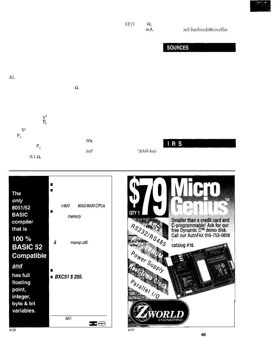
All of this is based on tempera-
ture-an ambient temperature of 20°C.
As the ambient temperature falls, the
hold and trip currents increase.
Conversely, as the ambient tempera-
ture rises, the hold and trip currents
decrease. This decrease is fairly
consistent: 1% per “C. For instance,
when the ambient temperature is 70°C
(i.e., 50°C hotter), a PTC device rated
to trip at 2 A trips at 1 A (i.e., 50% of 2
Normal resistance for untripped
PTC devices ranges from 0.05 to 20
The lower-voltage PTC devices have
the lowest nominal resistances. Once
tripped, the resistance is much higher
and can be determined by:
where is the applied voltage squared
and is the device’s power dissipa-
tion.
Typically, ranges from 0.5 to 4
W, depending on the device. Take, for
example, a
1-W PTC device that
is dropping 12 V and has been tripped
by a 3.7-A current. The device has a
tripped resistance of
or 144
limiting the current to about 80
The PTC device remains in the
tripped state as long as the fault
remains. In this state, the limited
current is sufficient to keep power
dissipation at a high enough level to
keep the device tripped. Only removal
of the fault condition enables the PTC
device to cool enough to recrystallize
to its low-resistance arrangement.
His background includes product
design and manufacturing. He may be
reached at
corn.
SO WHAT’LL IT BE?
Poly PTC
Raychem Corporation
Polyswitch Division
300 Constitution Dr.
Menlo Park, CA 94025-l 164
(415) 361-3333
Fax: (415) 361-7667
In many applications, the designer
has multiple solutions for current
protection. Device selection is based
on a combination of price and size.
PTC devices offer small size, UL
recognition, and automatic resetting.
The nuisance of having to replace
blown fuses alone makes this an easy
choice. Quantity pricing ranges from
to $1.
q
Ceramic PTC
Midwest Components, Inc.
P.O. Box 787
1981 Port City Blvd.
Muskegon, MI 49443
(616) 777-2602
Fax: (616) 773-4307
Bachiochi (pronounced
425 Very Useful
AH-key”) is an electrical engineer on
426 Moderately Useful
Circuit Cellar INK’s engineering
staff.
427 Not Useful
Memory mapped variables
in-line assembly language
option
n
Compile time switch to select
805
1 or
Compatible with any RAM
or ROM
mapping
n
Runs up to
50 times faster than
the MCS BASIC-52 interpreter.
n
Includes Binary Technology’s
SXA51 cross-assembler
hex file
n
Extensive documentation
n
Tutorial included
n
Runs on IBM-PC/XT or
compa tibile
Compatible with all 8051 variants
508-369-9556
FAX 508-369-9549
q
Binary Technology, Inc.
P.O. Box
l
Carlisle, MA 01741
from your FAX. Request
1724 Picasso Ave.
Davis, CA 95616
916.757.3737
916.753.5141
FAX
Circuit Cellar INK
Issue
July 1995
85
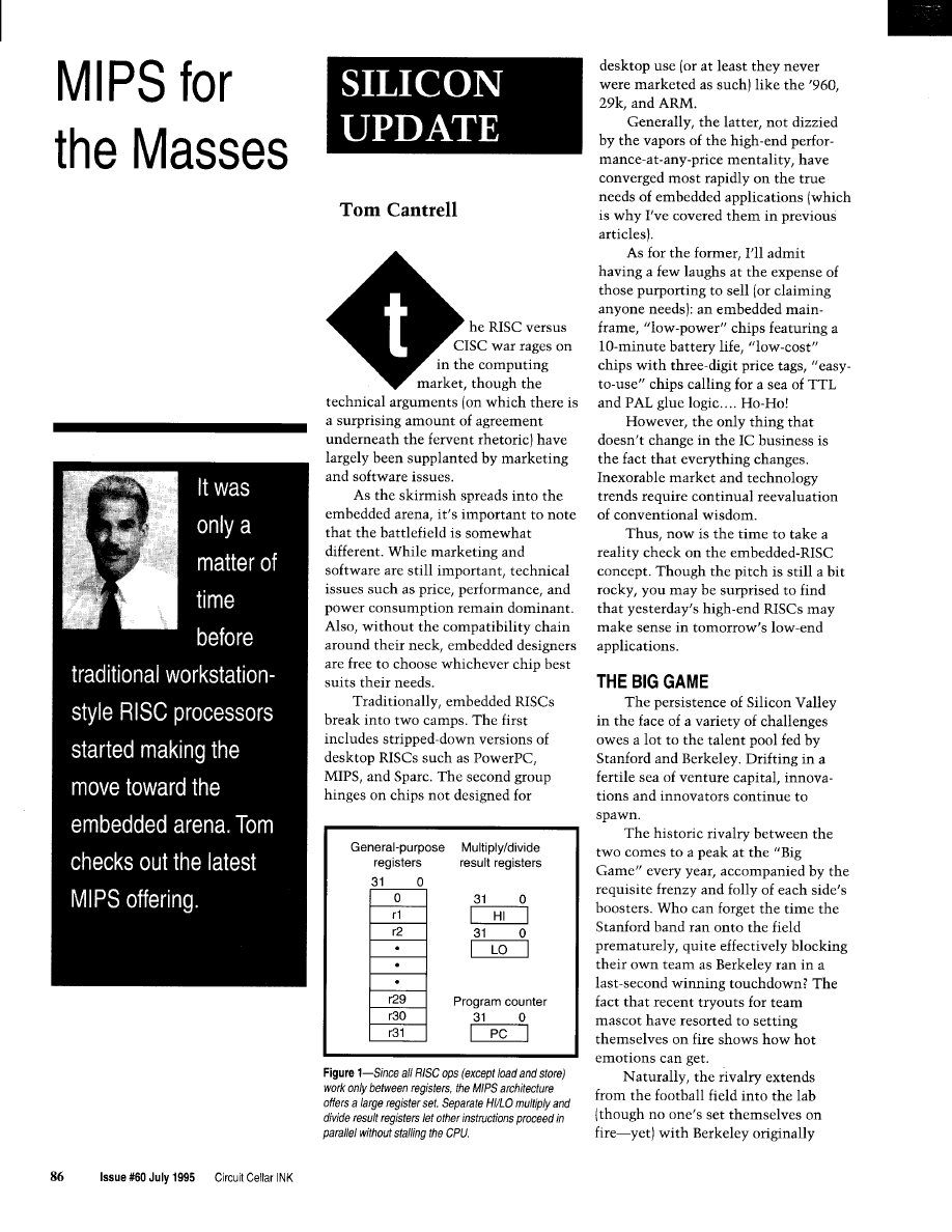
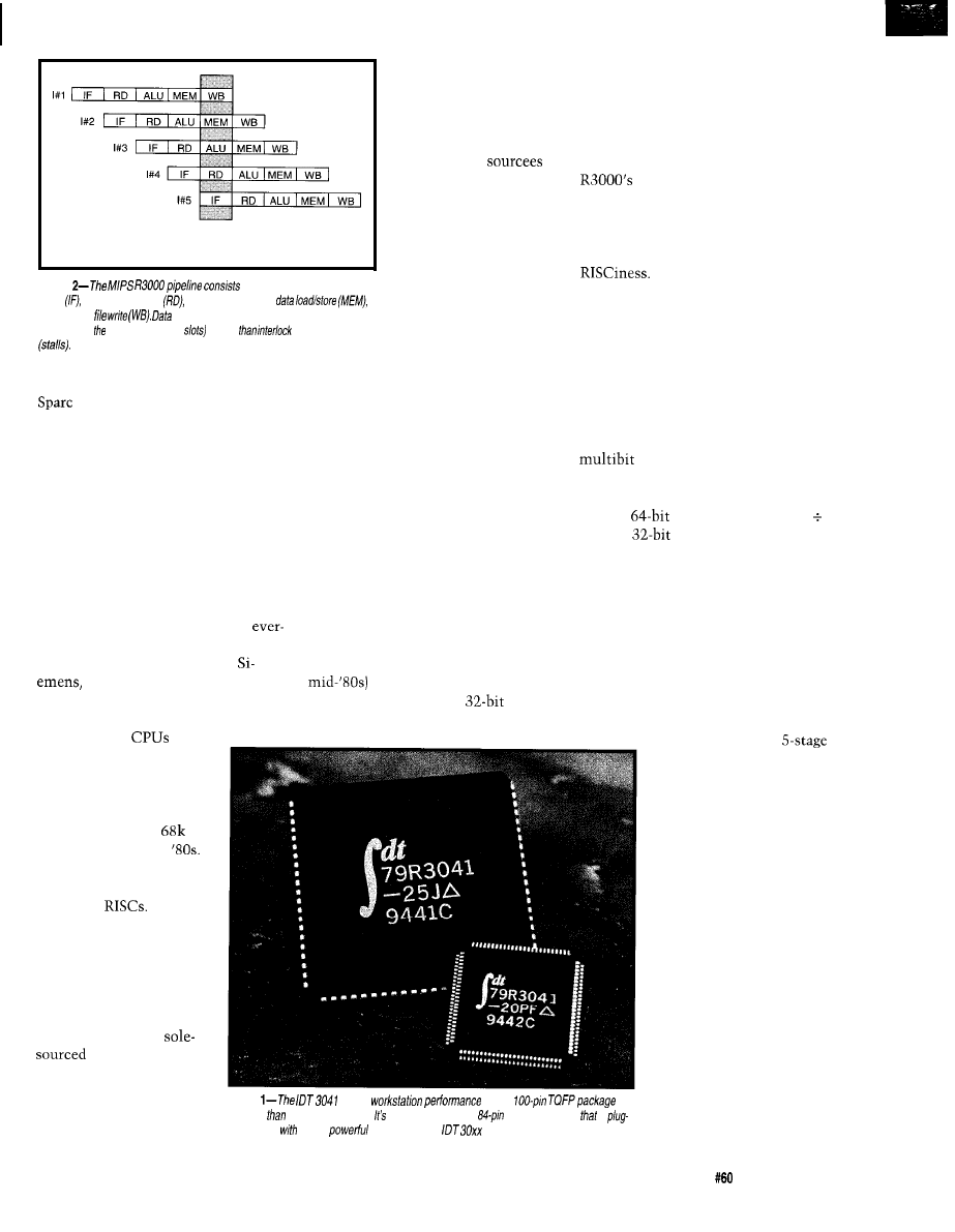
Current
C P U
cycle
Figure
of
five stages: instruction
fetch register file read
execution (ALU),
and
register
(load) and control (branch) hazards are
handled by compiler (delay
rather
hardware
A notable feature of
the MIPS alliance (shared
only by the ARM) is that
unlike other open (i.e.,
available to license)
architectures,
needn’t worry about
running up against their
source in the purchasing
lobby. Neither MIPS
(now part of SGI) nor
ARM manufactures or
sells chips, defusing the
love-hate relationship
that always seems to
fielding what has become the Sun
architecture and Stanford
responding with the SGI-blessed MIPS.
Competition between the two has
been and continues to be intense,
resulting in incredibly powerful chips
as each side fights for bragging rights.
drive other CPU mar-
riages of convenience to
the divorce court.
cooperation between the hardware
(CPU] and software (C compiler)
designers. Though the workstation
world has moved on to fancier
superscalar and speculative execution
techniques, I doubt they match the
bang per buck.
Though other RISC ideas have
blurred in the smoke and mirrors of
marketing battles, load-and-store
architecture remains the red badge of
The term refers to the fact
that instructions operate only on
registers, not memory. Naturally, this
scheme calls for lots of registers (32 x
32 bit), dedicated high and low
registers for multiply and divide, and a
PC (Figure 1).
RISC101
While most of the fireworks take
place in the ethereal world of worksta-
tions, I’ve particularly noticed that the
MIPS camp seems to be making slow
but sure progress toward the embedded
market. Most striking is the openness
of the MIPS architecture with an
growing lineup of suppliers including
IDT, LSI Logic, NEC, Toshiba,
Sony, and Philips. Indeed, the
sun never sets on the MIPS empire.
It’s somewhat ironic, given the
crosstown rivalry, that the captains of
each team (John Hennessy at Stanford
and David Patterson at Berkeley) have
jointly authored some of the best
books on computer architecture
including Quantitative Analysis of
Computer Architecture and Computer
Organization and Design. If you want
to understand the motivations and
ideas behind the RISC revolution,
check them out.
The era of plug-compatible
second-source
is
long gone. It never seemed
to work for either the
source or sourcee-witness
the Intel and AMD debacle
and the short-lived
Alliance of the early
As far as I know, there are
no multivendor clones for
embedded
In my opinion, the original (circa
MIPS R3000 CPU core is
arguably one of the best
integer
CPU cores around-thanks to close
With the exception of load and
store, nearly every instruction ex-
ecutes in a single cycle, including
shifts and rotates-thanks to
an on-chip barrel shifter. The only
notable exceptions are multiply (32 x
32 with
result) and divide (32
32 with
quotient and 32-bit
remainder), which take 12 and 35
clock cycles, respectively.
To speed those clock cycles,
pipelining is a must. The million-Hz
question is, “How many stages?” Too
few and the opportunity for high clock
rates is left on the table. Too many and
the pain from increased complexity
starts to exceed the gain (which itself
diminishes due to the dreaded condi-
tional branch]. The
MIPS pipeline of Figure 2
seems just about right. It’s
longer than most, but not
too long.
Nevertheless, the
MIPS bandwagon does
seem to guarantee a degree
of competition, if not at
the socket, at least at the
architectural level. Also,
compared to purely
designs, the MIPS
camp can offer both wider
and finer coverage of the
price-performance spec-
trum.
Photo
packs
info
a
smaller
most
B-bit
micros. also available
in
an
PLCC package
is
compatible
more
members of the
family.
To further simplify
(and thus speed] the
pipeline, the MIPS archi-
tecture dismisses hardware
interlocks (i.e., stalls) for
handling certain pipeline
hazards in favor of com-
piler scheduling. Load and
branch instructions are
followed by a delay slot,
which the compiler
attempts (successfully
about half the time) to fill
with useful instructions.
Even those pesky loads
and stores can often be
dispatched in a single
Circuit Cellar INK
Issue
July 1995
8 7
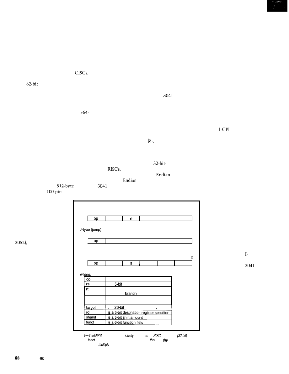
cycle,
thanks to on-chip cache. A key
feature of the MIPS architecture is
Harvard cache organization (i.e.,
separate instruction and data caches
can be accessed simultaneously). In
furtherance of the need for speed,
MIPS traditionally relies on simple,
direct-mapped, write-through caches.
In response to the baroque,
arbitrary instruction length of
MIPS adheres to a brutally simple
fixed
instruction format (see
Figure 3). There’s some validity to the
argument that code density suffers
from such a scheme. However, it’s my
experience that the effect diminishes
with the size and 32-bitness (i.e.,
KB programs with long integers and
pointers to big memory) of the applica-
tion. In fact, the code-density issue
may be hidden in the ever-increasing
capacity and coarser granularity of
practical memory setups.
BIG RISC IN A SMALL PACKAGE
One of the most embeddable MIPS
chips available today is the 3041 from
Integrated Device Technology. It
combines an R3000 integer core with
2-KB instruction and
data
caches in a tiny
TQFP (Thin
applications, though nothing compared
to the latest desktop chips. However,
the truly power conscious can hop on
the 3.3-V bandwagon, which cuts
power to a more acceptable 0.5 W or
so.
Getting full 32-bit addresses and
data into and out of such a tiny chip
does call for some compromise,
namely a multiplexed address/data bus
(see Figure 4). Besides address latches,
tight bus timing typically dictates the
use of data transceivers to avoid bus
contention as well. However, the
uniquely offers slow bus turnaround
and extended address-hold timing
options, giving the designer the option
of dispensing with the transceivers at
the expense of some performance.
Further reflecting the realities of
the embedded world, the 3041 has
programmable bus width
16-, and
32-bit) capability. Notably, this feature
enables use of a single x8 boot
(EP)ROM rather than the parade of
four chips that accompanies
only
When it comes to the Big
versus Little
controversy, the
says have it your way, supporting
not only selection at reset, but even
dynamic switching between modes.
Needless to say, the latter practice
could lead to some rather interesting
debugging sessions, so take care.
The 3041 even includes an on-chip
24-bit timer that’s a likely candidate
for a variety of timing duties such as
triggering DRAM refresh or generating
an RTOS tic. The single output line
can be configured to pulse or latch low
on timeout.
QUIT STALLING
When things are going smoothly,
the 3041 cranks an instruction through
the pipeline on every clock. Except for
overtly uncacheable references (such
as I/O) and a multiply or divide from
time to time, the only things that
stand in the way of
[clock per
instruction) nirvana are cache misses
and writes (remember the data cache is
write through).
To deal with the latter, the 3041
includes a four-deep write capture
buffer. The buffer can hold up to four
pending writes captured at the proces-
sor rate. The information is then
stored in slower external memory
later. In the meantime, the processor
continues to execute from cache.
31
26 25
21 20
16 15
0
rs
immediate
l-type (immediate)
31
26 25
R-type (register)
31
26 25
21 20
16 15
1 1 1 0
6 5
rs
rd
shamt
funct
target
0
is a 6-bit operation code
includes specific features
is a
source register specifier
is a 5-bit target (source/destination)
for low-end applications.
register or
condition
Thanks to smallish
immediate
is a 16-bit immediate, branch
cache size and derated
displacement or address displacement
clock (only up to 33
is a
jump target address
MHz!), the 3041 is the
lowest-power family
member. Full-speed, 5-V
operation calls for almost
2 W, which is still kind of
Figure
instruction set
adheres the
fixed-length
hot for most embedded
instruction
Furthermore, besides loads and stores
miss cache, every
instruction (except
and divide) executes in a sing/e clock.
Quad Flat Pack) plastic
package (see Photo 1).
The 3041 is the entry
point to a complete lineup
of 99% plug-compatible
parts that includes
versions with larger
caches (e.g., 3051 and
TLB (translation
lookaside buffer) for
virtual memory (E
versions), and built-in
IEEE floating point (308 1).
However, the 3041 is
clearly the leanest and
meanest of the bunch, and
Thus, the write penalty is
largely hidden, though an
in-order memory-update
policy does dictate that a
cache miss stalls until
the write buffer drains.
Instruction-cache
misses take advantage of
DRAM burst mode to
speed refill. Given the
locality of code, the
cache line size is four
words, meaning the
always loads four words
sequentially in response
to an I-cache miss.
Streaming is also sup-
ported, which means that
the processor exits the
stall as soon as the
needed word appears,
even as the cache
continues to refill.
Since data usually
exhibits less spatial
locality than code, the
data-cache line size is one
Issue
July 1995
Circuit Cellar INK
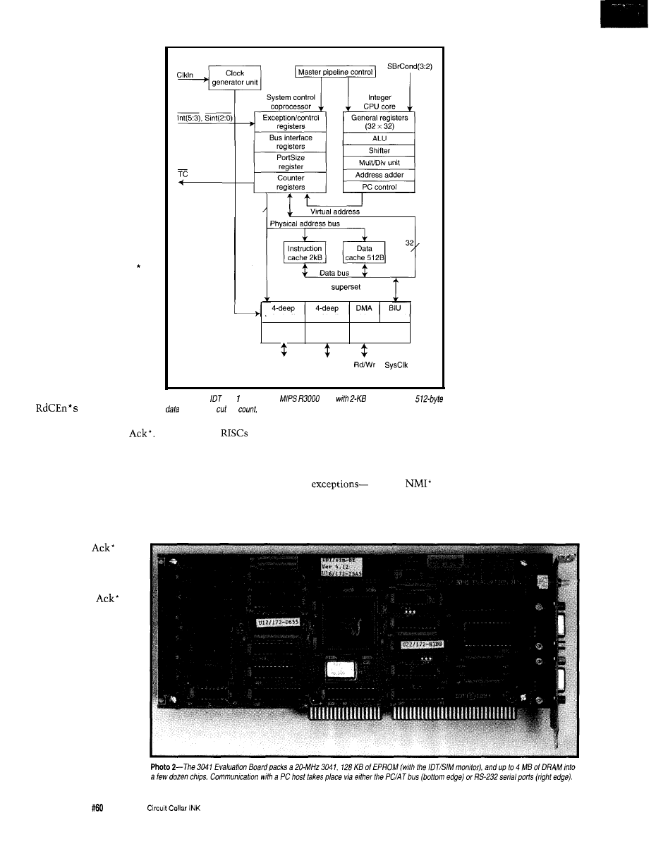
(i.e., only a single word
need be loaded to satisfy a
miss). Nevertheless,
sequential data operations
(such as array, buffer, or
bitmap accesses) can take
advantage of a four-word
data-cache refill option.
Indeed, the refill-size
selection can be made
dynamically, giving the
programmer overt choice
in the matter.
Burst refill places
demands on the system
designer to drive two
inputs: RdCEn* (Read
Clock Enable) and Ack
(Acknowledge). The
former signals the avail-
ability of each word in the
burst, while the latter
signals the end of the
transfer.
You may wonder why
both are needed-after all,
the CPU can certainly
count the number of
to determine
when the cycle is finished
registers
register
Counter
registers
3 2 ,
R3051
bus interface unit
write buffer
read buffer
arbiter
control
Data
Data
Timing/interface
unpack unit
pack unit
control
1
-
-
Address/
DMA
data
Ctrl
Ctrl
Figure
4-The
304
combines a
core
instruction and
caches. To pin
a multiplexed address/data bus is used.
and generate its own
Indeed, the
is their cavalier attitude toward
3041 offers this option, thereby
interrupts. I must say, at first glance,
simplifying the required memory
it’s tempting to criticize the MIPS
interface logic.
architecture in this regard.
However, true speed freaks can
take advantage of overt Ack* control
to wring a little more parallelism out
of the bus interface. RdCEn* actually
clocks data into a read
buffer while
dumps it into the
cache and releases the
stall. As it turns out,
you can treat
as
a promise to deliver
the data on time and
issue it early, starting
the cache transfer and
possibly ending the
stall even before the
last word is delivered
from memory.
First, almost all
address and bus error, SY
SC
A L L,
breakpoint, unimplemented instruc-
tion, overflow-not to mention the six
EXCEPTING THE
INEVITABLE
One common
complaint about
workstation-like
90
Issue
July 1995
hardware and two software
interrupts are mushed
together and funneled
through a single exception
vector. It’s up to the
programmer to examine
the so-called CAUSE
register to figure out
what’s going on.
The 3041 stacks
nothing in memory in
response to an exception.
Instead, it just shoves the
old PC into a register
(EPC) and leaves the rest to
you. Sure, you don’t have
to stack the PC, but be
real careful that your
exception handler doesn’t
itself generate an excep-
tion-at which point
you’re toast.
Reflecting the true
spirit of RISC, support for
interrupt priority is rather
reduced. In fact, there isn’t
any! An exception simply
turns off all interrupts, and
if you want to handle
nested or prioritized
interrupts, feel free to diddle with the
individual and global interrupt-enable
bits.
They even forgot to provide a real
(i.e., errant software can disable
all interrupts). Oh well, the ‘51 has
gotten by for many years without one,
so it must not be that big a deal.
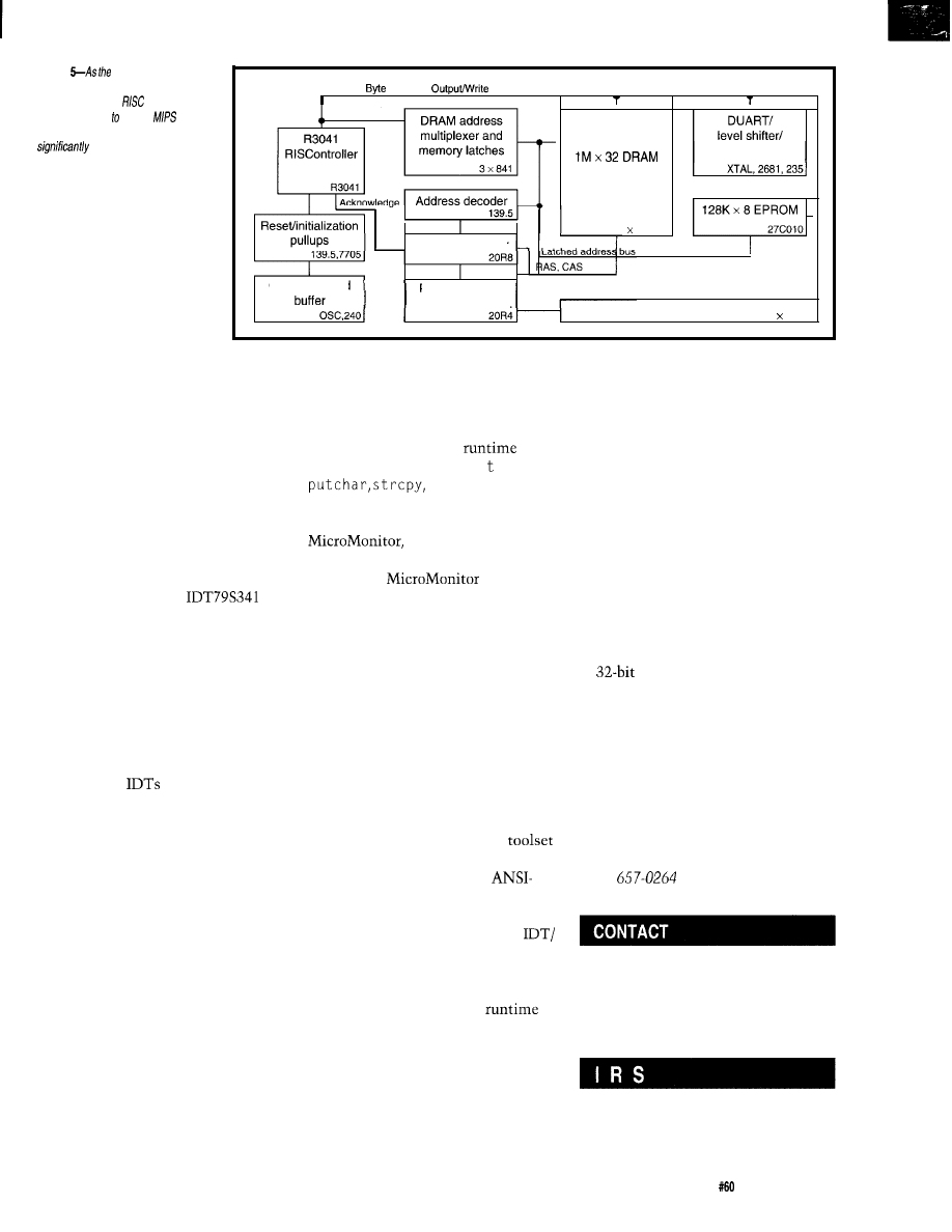
Figure
3041 evaluation
board
shows, designing in a
workstation-class
is easier than
ever. Compared earlier
chips,
the amount of glue
logic required is
reduced.
ND bus,
Enables,
Enables
bank
RS232 connectors
Memory controller
8 514256
Clock OSC and
PC/AT interface
controller
521,
PC/AT registers
2 652
It all sounds rather
grim, but actually I’ve
become less critical as
time goes on-so what if it
takes a few dozen instruc-
tions to clean up after
interrupts? After all, that’s
only about a microsecond
or so.
Furthermore, I kind of like the
idea that I can implement any darn
interrupt scheme (priority, nesting,
how much gets stacked, etc.) I want
without stumbling over someone
else’s preconceived notions. And as for
NMI*, I imagine there are ways to fall
back on other exceptions (perhaps bus
error or, in a pinch, there’s always
RESET).
LESS FILLING, TASTES GREAT
Photo 2 shows the
Evaluation Kit fbr the 3041. Any of
you who have designed with worksta-
tion-class RISC chips must be im-
pressed with remarkable downsizing.
In fact, thanks to 3041 streamlining
features like the slow bus turn (i.e., no
data buffers) and programmable bus
width (one EPROM instead of four),
the 3041 board achieves basically the
same specs as
earlier 305 1 board
with half the chips. It’s nice that,
when it comes to recognizing the
realities of embedded applications, the
RISC folks are finally starting to get it.
Figure 5 shows the block diagram
of the board. Notice the tiny amount
of glue logic required-little more than
address latches, DRAM address mux,
and a memory-control PAL.
If the form factor doesn’t give it
away, communication with the board
can take place over the PC/AT bus (for
highest speed downloading) or via the
more conventional serial port.
The ROM contains IDT/SIM, a
rather full-featured monitor. Besides
the usual commands (memory dump,
go, etc.), it includes a quick-and-dirty
assembler/disassembler (great for
fiddling with small routines without
hauling out the entire arsenal of tools)
and the commands needed to deal with
the cache (read, write, flush, etc.). It
even offers a number of
entry
points (such as C-like p r i n f,
etc.)
that you can
wrap your code around.
The package also includes
a minimal kernel for
debugging your own design. All you
need to run
is the CPU,
EPROM, and a serial port. It’s just the
thing for debugging your DRAM
interface, the area that usually causes
the most head scratching.
The latest version of the ROM
also includes an ICE-like trace facility
that tracks execution based on qualifi-
ers such as instruction, data read, data
write, memory range, and so on. Sure
it isn’t real time, but it is real cheap!
The budget conscious will be
further pleased to find that the
evaluation kit includes a complete
DOS-based cross-development
from the increasingly popular GNU
technology. It consists of an
compliant compiler
(GCC),
an assem-
bler (GAS), linker (GLD), and debugger
(GDB). The debugger works with
SIM to offer remote (i.e., via the PC/
AT bus or serial port) C source-level
debugging.
Besides the standard C
library and a variety of example
routines (cache initialization, excep-
tion handling, etc.), a key extra is a
floating-point library.
Traditionally, floating point on
integer MIPS chips has been handled
by emulating the original MIPS FPU
(the 3010) using software traps. The
good thing about such a scheme is that
a single binary can run transparently
on a system with or without FPU.
However, truly mimicking the
FPU is quite messy and slow since
even minor operations not only incur
trap overhead, but have to save and
restore a zillion FPU registers and
intricately fake a variety of status and
control bits. So, IDT provides a
floating-point math library that
dispenses with FPU emulation in favor
of dedicated code that runs as much as
10 times faster.
If it isn’t plain to see that the era
of
embedded RISC is close at
hand, let me spell it out for you. The
EV kit is only $795 and 3041s start at
$9.60. If you’re ready for life in the fast
lane, hang on to your logic probe and
hitch a ride on a MIPS chip.
q
Tom Cantrell has been working on
chip, board, and systems design and
marketing in Silicon Valley for more
than ten years. He may be reached at
(510)
or by fax at (510) 657-
5441.
Integrated Device Technology, Inc.
2975 Stender Way
Santa Clara, CA 95054-3090
(408) 727-6116
Fax: (408) 492-8674
428 Very Useful
429 Moderately Useful
430 Not Useful
Circuit Cellar INK
Issue
July 1995
91
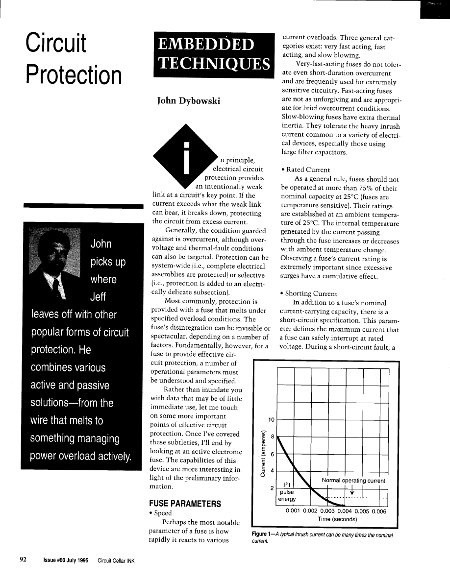
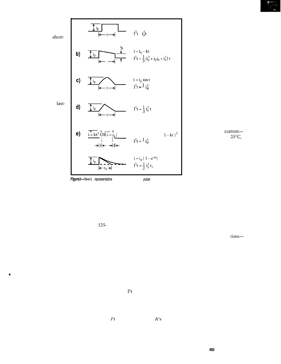
fuse may receive an instanta-
neous overload current many
times greater than its normal
operating current. The
circuit parameter (also called
the interrupt rating)
sets
the
upper limit of current that
the fuse can safely handle. If
this limit is not exceeded,
the fuse remains intact and
clears the circuit.
a)
i=k
=
l
Temperature
Most slow-blow fuses
use materials that melt at
lower temperatures than
acting and very-fast-acting
fuses. As a result, they are
more sensitive to changes in
ambient temperature.
t
2
l
Resistance
An often neglected fuse
parameter is its resistance
since, in many cases, resis-
tance is not significant at all.
However, with low-voltage
applications served by frac-
tional-amperage fuses, you
t
5
f)
may no longer be able to
disregard this parameter.
a
collection of
transient
current waveforms
and their associated equations for calculating pulse Pt.
applied to the fuse to cause
melting. If melting does not
occur within 8 ms or less,
the pulse current is in-
creased. This test is repeated
until the fuse melts within
the specified time frame. The
stipulation of 8 ms for melt-
ing guarantees that the heat
does not have sufficient time
to be thermally conducted
from the fuse element.
PICK ONE
Fuse selection involves a
survey of the operational
conditions surrounding the
electrical system. These
conditions could include:
l
normal operating
assuming operation at
the current rating of the fuse
would be derated 25 % typi-
cally.
l
AC or DC application volt-
age-except for special condi-
tions, the fuse’s voltage rat-
ing should be equal to or
greater than the available
Values of several ohms are com-
mon. Most fuses are manufactured
from materials that have positive tem-
perature coefficients, so it is common
to give cold and hot resistances (volt-
age drop at current). As you’d expect,
operation typically falls somewhere in
between. Cold resistance is the resis-
tance obtained using a measuring cur-
rent of no more than 10% of the fuse’s
nominal rated current while hot resis-
tance is calculated from the stabilized
voltage drop across the fuse with cur-
rent equal to the normal rated current.
Voltage
A fuse’s voltage rating indicates
that it can safely interrupt (i.e., no
rupture, explosion, or other undesir-
able side effects) a voltage that does
not exceed its rating. Since fuses are
sensitive to current and not voltage,
this parameter usually indicates the
safe upper limit for preventing unan-
ticipated related events.
Under certain conditions, it is
acceptable to exceed the voltage rating.
For example, electronic equipment
with relatively low-output power sup-
plies have circuit impedances which
limit short-circuit currents to 10 times
the current rating of the fuse. In such a
case, it is common to specify fuses
with
or 250-V ratings for second-
ary circuit protection of 500 V or
higher.
To clarify, a fuse may always be
used in a circuit with voltages less
than its rated voltage. It may also be
used with voltages higher than its
rated voltage if the maximum power
level the fuse is subjected to under
short-circuit conditions only produces
a low-energy, nondestructive arc.
l
Nominal Melting:
l
ambient temperature-the higher the
ambient temperature, the hotter the
fuse operates. A fuse also runs hotter
as the operating current approaches
the fuse’s rating. However, a fuse
should last indefinitely if operated at
room temperature at no more than
75% of its nominal rating.
l
overload current and overload
these are the parameters fault pro-
tection is specified for. In other
words, fault conditions can be speci-
fied in terms of the current or of the
current and time till damage.
l
maximum fault current-the maxi-
mum fault current should fall below
the fuse’s maximum short-circuit
specification to ensure safe opera-
tion.
Tests are performed on a fuse to
l
inrush and pulse current-inrush or
determine the amount of energy re-
pulse current encompasses the broad
quired to melt the fusing element.
category of wave shapes that in-
This energy is described as the nomi-
cludes inrush and start-up currents,
nal melting and is expressed as
surge currents, and other current
(ampere squared seconds).
transients. Pulse currents produce
To determine this parameter, the
thermal cycling that affect the life of
time is measured for a pulse of current
a fuse.
circuit voltage.
Circuit Cellar INK
Issue
July
1995
93
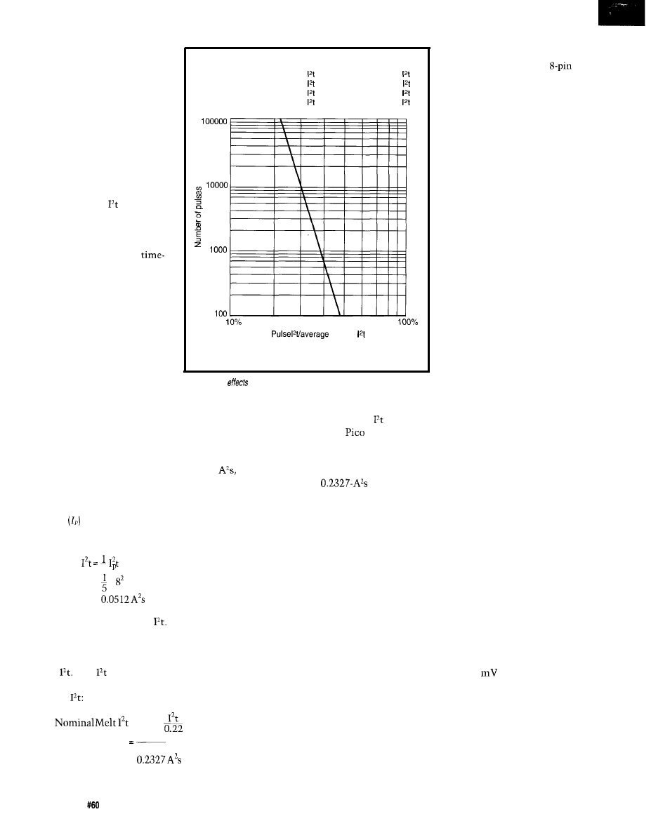
Since start-up inrush cur-
rents are unavoidable in a
variety of electrical circuits,
thermal delay fuses, such as
the slow-blow type, are de-
signed to help them survive
such pulse phenomena while
still providing adequate pro-
tection during continued fault
conditions.
PULSE CYCLE WITHSTAND CAPABILITY
100,000 pulses
Pulse = 22% of normal melting
10,000 pulses
Pulse = 29% of normal melting
1,000 pulses
Pulse = 38% of normal melting
100 pulses
Pulse = 48% of normal melting
In any case, start-up
pulses should be defined and
compared to the
rating of a
fuse. Once this rating is
known, the resulting wave
shape should be compared to
the fuse manufacturer’s
current curve. Combining this
information with normal oper-
ating currents, derating, and
ambient operating tem-
perature gives the selection
criteria for the fuse.
For example, suppose a
melting
fast-acting fuse is required for
a given application. Assume
the fuse must be capable of
withstanding 100,000 current
Note: adequate time (IO seconds) must exist between
pulse events to allow heat from previous event to dissipate.
Figure
3-The
of pulse-current phenomena must be considered
because fhey are cumulative.
Figure 4 shows the
LTC 1153 in block form. From
this, you can see that the IC
contains a built-in voltage
regulator, current-sense am-
plifier, various timing cir-
cuits, and an N-channel
MOSFET charge pump.
provides highly integrated
precise protection. This
IC drives a low-cost N-chan-
nel MOSFET that supplies (or
interrupts) current to an ex-
ternal electronic load. The
trip current, trip delay, and
autoreset period are program-
mable and can operate over a
wide range of values.
An external PTC ther-
mistor can be added when
thermal faults must be
guarded against. As a bonus, a
digital on/off pin enables
external logic to control
power to the external load.
An open-drain status pin pulls
low to indicate that the elec-
tronic breaker has tripped and
that the protected system is
in fault status.
pulses of the wave shape
shown in Figure 1. The ambient oper-
ating temperature is 25°C and the
nominal operating current is 0.75 A.
Reference to the fuse
manufacturer’s wave shape table
shown in Figure 2 reveals that wave
shape (e) should be used for the sub-
sequent calculations. The peak pulse
current
and time (t) yields the fol-
lowing calculation:
5
= x x 0.004
=
This value yields the pulse
Figure 3 indicates that a figure of
22% should be used for a value of
100,000 occurrences of the calculated
pulse
This
pulse is now con-
verted to the required value of nominal
melting
= Pulse
0.0512
0.22
=
Examining the manufacturer’s
rating data for the Littlefuse
I
I
125-V very-fast-acting fuse reveals that
the 1-A 2510001 part is rated at 0.281
which is the minimum rating that
satisfies the calculated
value. This fuse also meets the 0.75-A
nominal current criteria when derated
by 25% for operation at an ambient
temperature of 25°C.
ELECTRONIC BREAKING
Undoubtedly, fusible links are the
most common method of providing
reliable, inexpensive circuit protec-
tion. However, a number of alternative
technologies (most notably mechanical
circuit breakers) are an advantage
when your needs are more specialized.
With most of these devices, their
various operating parameters (melting,
thermal inertia, resistance, etc.) are
linked by their manufacturing process.
When precise control of the individual
parameters is necessary, it’s best to
combine various active electrical com-
ponents.
Linear Technology’s LTC 1153
Auto-Reset Electronic Circuit Breaker
Certainly, these elements are
familiar to engineers. As is often the
case, it’s the way these capabilities are
combined in a single piece of silicon
that makes the device unique and
useful. To gain an appreciation for the
device’s refinement, let me briefly
touch on the design’s various function
blocks.
l
input and shutdown pins-The
LTC 1153 has an active-high control
pin that activates all protection and
charge-pump circuitry when as-
serted. The shutdown pin breaks the
circuit when used in conjunction
with a PTC thermistor if a second-
ary overtemperature fault is de-
tected. These pins switch at 1.3 V
with about 100
of hysteresis
and, as a result, can handle a variety
of logic family outputs.
l
auto-reset timer-Using an external
timing capacitor, a ramp voltage is
generated each time a fault condi-
tion is detected. When the timing
ramp reaches 2.5 V, the switch is
turned back on and the capacitor is
9 4
Issue
July 1995
Circuit Cellar INK
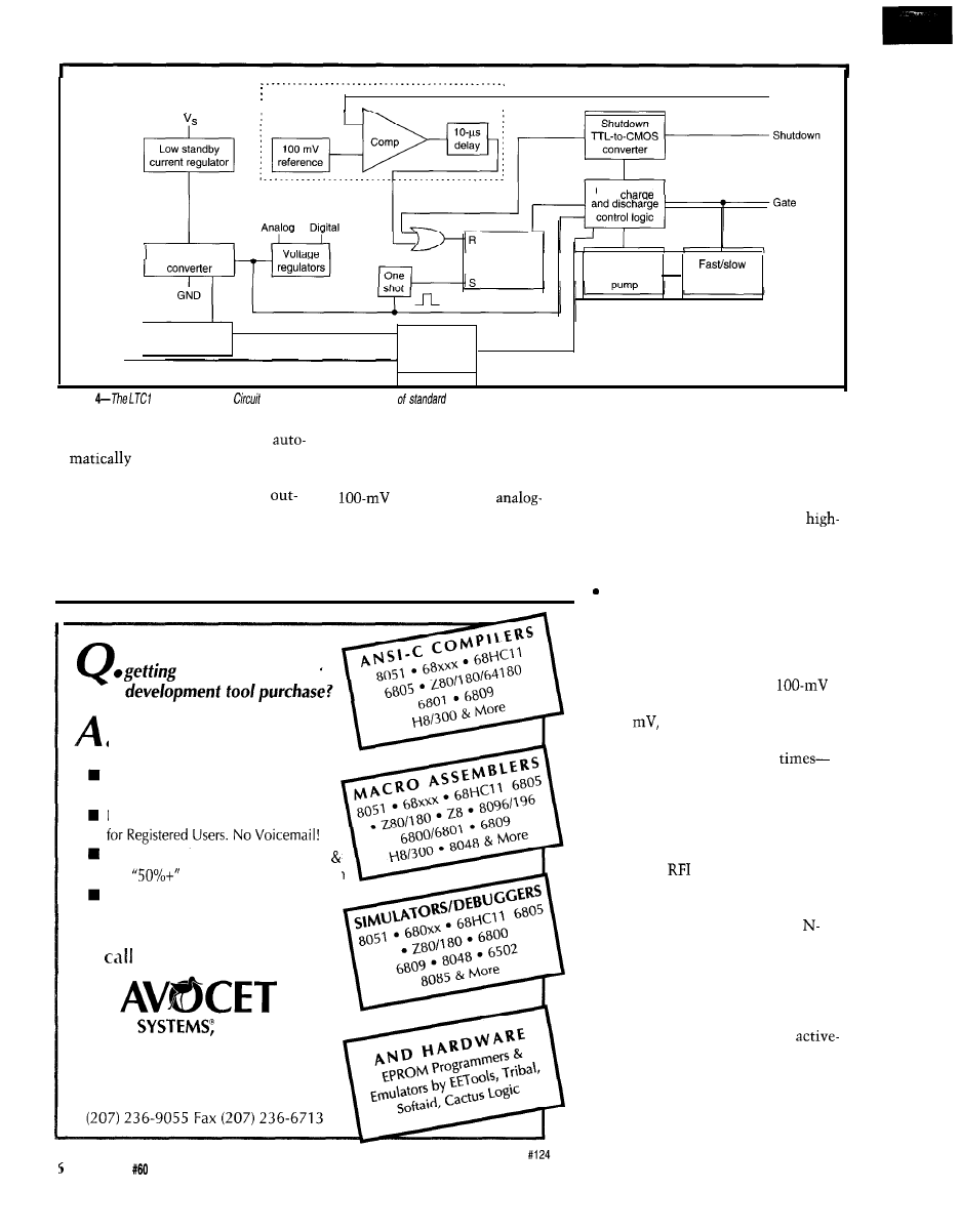
Input
TTL-to-CMOS
Analog section
Drain sense
Gate
Input latch
Oscillator
and charge
gate charge
logic
Timer cap
Status
Auto-reset
Fault detection
timer
a n d s t a t u s
output driver
Figure
153 Electronic
Breaker is a unique combination
functions.
discharged. This can be used to
outputs of the regulator are isolated
pump circuit. The resulting gate
reset the breaker after a
so that noise generated by the charge
voltage is substantially higher than
fixed fault duration.
pump logic does not couple into the
the power-supply voltage, enabling
l
internal voltage regulator-The
reference or the
the designer to use an inexpensive
put of the internal TTL-to-CMOS
comparator section.
external N-channel device as a
converter drives the regulated supply
l
gate charge pump-The gate drive for
side switch. The charge-pump ca-
which powers the low-voltage
the N-channel MOSFET switch is
pacitors are included on-chip to
CMOS logic and analog blocks. The
generated by an adaptive charge-
further save space.
drain current sense-Current flowing
into the drain of the N-channel
MOSFET switch is monitored using
a low-value external sense resistor.
The voltage drop across this resistor
is compared to an internal
reference. If the voltage drop exceeds
100
the input latch is reset and
the gate drive discharged.
r
How do you know you’re
the most from your
Compare Avocet Systems
. with the competition.
A Broad Line of High-Quality
Products at Competitive Prices
Free On-Line Technical Support
Attractive Multi-User Discount Prices
Our
Educational Discount Plan
Unconditional 30-Day
Money-Back-Guarantee
Now
the obvious choice!
INC.
The Best Source for Quality
Embedded System Tools
(800) 448-8500
l
controlled gate rise and fall
When the input is switched on and
off, the gate is charged and dis-
charged by the internal charge pump
in a controlled manner. The charge
and discharge rates are set up to
minimize
and EM1 emissions
during normal operation. Under
overload conditions, the gate dis-
charges very quickly by a large
channel transistor turning off the
external N-channel MOSFET as
quickly as possible.
l
status output driver-Status circuitry
continuously monitors the input and
gate-charge control logic. The
low open-drain status indicator is
driven when the breaker is latched
off (fault condition). The status cir-
cuitry resets with the auto-reset
circuitry.
Issue
July 1995
Circuit Cellar INK
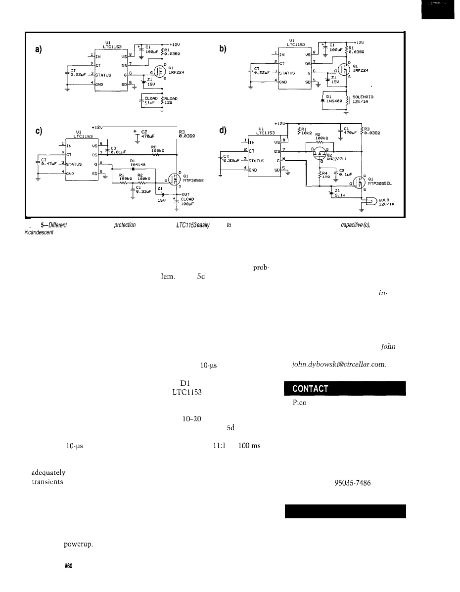
Figure
loads have different
requirements. The
adapts
a number of conditions: resistive
(a),
inductive (b),
and
lamp (d).
IT’S HOW YOU USE IT
The LTC1153 offers a great deal of
flexibility in the selection of various
parameters such as initial hold-off
delay, break current, and autoreset
time. Additionally, the IC is easily
configured to guard against thermal
faults and overvoltage. Linear Tech-
nology’s application notes provide
endless ways to configure the elec-
tronic breaker to handle just about
every imaginable fault condition.
Let’s briefly look at several differ-
ent configurations that illustrate how
to handle typical load circuits:
l
resistive and inductive loads-These
loads require as short a delay as
possible to minimize the amount of
time the load and the MOSFET
switch arc subject to overcurrent.
The LTC 1153 drain-sense circuitry
has a fixed
fault delay that
prevents false tripping under power
supply or load transients. This delay
masks short load-current
and small capacitive start-
up surges. Figures 5a and b depict
this simple circuit.
l
capacitive loads-Circuits with large
bypass capacitors are traditionally
protected using slow-blow fuses
since they can absorb heavy inrush
current at
Rather than just surviving, the
LTC 1153 lets you balance circuit
parameters so you can fix the
Figure shows how the gate
drive to the MOSFET is passed
through an RC delay network that
controls the turn on ramp of the
switch. As the MOSFET source
voltage follows the gate voltage, the
load is gradually powered up, reduc-
ing power-supply transients.
Once the system comes to full
power, the LTC1153 reacts within
the nominal
fault delay for a
short-circuit condition. Note that
diode
provides a direct path to
the
discharge control cir-
cuitry for controlled or fast turn off.
l
Lamp Loads-Lamp turn-on currents
can be
times higher than the
rated current. Figure illustrates
how the trip current can be shifted
upbyafactorof
for
when the lamp turns on. Following
this surge, the trip current drops to
the nominally configured level.
But, in your concern to protect,
don’t forget there are cases when it is
perfectly appropriate not to provide
any protection at all.
q
John Dybowski is an engineer
volved in the design and manufacture
of embedded controllers and commu-
nications equipment with a special
focus on portable and battery-oper-
ated instruments. He is also owner of
Mid-Tech Computing Devices.
may be reached at (203) 684-2442 or
at
II
Littlefuse, Inc.
800 E. Northwest Highway
Des Plaines, IL 60016
(708) 824-0400
LTC1153
Linear Technology
1630 McCarthy Blvd.
Milpitas, CA
(408) 432-1900
Circuit protection takes on many
forms. With more protective compo-
nents appearing on the market, the
selection process can be even more
confusing. A wide range of factors
must be weighed when selecting a
protective device for an application.
.
431
Very Useful
432 Moderately Useful
433 Not Useful
98
Issue
July 1995
Circuit Cellar INK

The Circuit Cellar BBS
bps
24 hours/7 days a week
(203) 871-l 988-Four incoming lines
Internet E-mail:
Since
this month’s issue includes the Home Automation Building
Control insert,
decided to
off this month’s column with an X-
10-related thread. Although the original question is simple, the
answer can be very complicated if you want to know all the back-
ground
In the other thread, we risk starting a language religious war by
asking, “Which is better: Forth or C?” The responses are remarkably
civilized and consistent.
X-l 0 Fan Control
From: Darrell
To: All Users
Greetings. I have a problem with a recently installed
ceiling fan/light combination. It is presently controlled by
an X-10 wall switch module, and when on, the thing is
horrendously noisy. With only the fan switched on, the
noise is a little less than with both fan and light, but it’s
still obnoxious. Also, the X-10 unit will turn on the unit
with the fan only, but not off. With the light switched in,
on/off control seems to work fine.
I assume that the on/off switching problem has some-
thing to do with the inductive load of the motor, possibly a
suitable snubbing network across the switch will take care
of this, but what about the noise? I have seen low-noise fan
speed controls in the local electrical supply houses. How do
they work? Is it possible to modify the X- 10 wall switch to
eliminate the noise problem? Is there a special X- 10 module
for fan speed control?
From: Ken Davidson To: Darrell
The X-10 wall switch module may be used to control
lights *only*. You’re going to burn out the switch, the fan,
or both by having it connected the way you do.
does have a true fan-control wall switch
module that can be used in your setup. I’ve heard lots of
complaints about it being noisy as well. You might want to
try it, though. Contact any of the usual module sources
such as Home Control Concepts, HAL, and so forth (Radio
Shack can special order it).
From: Pellervo Kaskinen To: Darrell
While I have no personal experience with X-IO, I gather
it is time to discuss the two problems you have described
from a “theoretical” point. I added the quotes there to
emphasize that I try to present educated guesses.
Your first point is that the X-10 can only switch the fan
off if the light is connected in parallel. This is not unique to
X-10. Any triac circuit has fundamental difficulties in
turning off when it has an inductive load. And that is
something that I *do have experience with.
Starting with the data sheet for any triac, we find at
least two relevant pieces of information. One is the noise
immunity limit: how fast can the voltage rise between the
main terminals without the triac turning on. It can be given
as a single number with a fixed load between the gate and
the “low end” main terminal, or it can be given as a graph
versus the gate impedance.
The second important issue is a discussion about
snubber networks required under inductive loads. If you
work the given data back to the rate of voltage rise, it turns
up being related to the first issue, but not the same....
There is the need to turn off, while the first number
was given as a guidance against false triggering. Internally,
there are some charge carriers that have to migrate from the
saturated interfaces to the bulk material or to the external
connections before there is again a voltage being applied.
This migration takes time. With more time, the saturation
characteristics are better, and there is more current just
prior to the turn-off attempt.
You have heard that inductive current lags the supply
voltage. You may even remember that it lags by YO”. Now,
what does it mean for the triac? It means that the current
may be very close to the maximum at exactly the point
where the voltage reverses. Not the kind of gradual decay
that a light bulb load gives with a sine wave supply. In fact,
the inductive portion of the current is quite adamant about
continuing just as it is, regardless of whether a triac
somewhere in the loop wants to turn off.
Note that I say “inductive portion.” If you have a light
bulb connected in parallel with the motor winding, you get
a resistive portion and an inductive portion. If each is 1 A,
the vector sum is 1.4 A, with 45” of phase lag. If the
100
Issue
July‘1995
Circuit Cellar INK

resistive load is 2 A and the inductive remains at 1 A, then
the combined current is 2.2 A at a phase lag of some 26”.
Pick your choice for any combination of resistive and
inductive current; you always have a phase lag *and’ a
remaining current at the voltage zero-crossing point. In fact,
that current remains the same whether you change the
resistive load or not. Why then does the light bulb help the
triac!
It simply gives another path for the inductive current to
divert when the triac is able to muster a little resistance.
The lower the resistance (higher the load in watts or
kilowatts), the better bypass route there is.
You mention a possibility of a suitable snubbing
network taking care of the turn-off. It may or may not,
depending on how much money you are willing to spend on
that. A use in snubber duty is not easy on capacitors, which
means that the garden variety polyester capacitors fail in
short order, sometimes bursting into flames. You need
polypropylene or oil paper AC capacitors to stand a chance.
Now, a different viewpoint: If you are using capacitors
in general, don’t they compensate for the phase lag of the
inductive loads?
They do, although not in the usual way of connecting a
snubber network over the triac. And not too much with the
small-value capacitors that normally are used. But, if you
put a real capacitor over your inductive load-something
that also takes 1 A from the power line (when alone)-you
are truly compensating the inductive load. Wouldn’t the
triac love that?
Maybe. But there is a complication or two. First, is the
fan motor current fixed so that you could accurately
compensate for it? Second, you may have to deal with a
nice resonance at the primary frequency plus some possi-
bilities of hitting resonances at the harmonic frequencies.
Now, did you want to control the speed of the fan with
the triac? If so, you are dealing with a mighty harmonics
generator. If you put in enough capacitance to resonate at
the fundamental frequency, the harmonics would appear to
be attenuated and consumed by the same capacitor. But,
you better check if the capacitor can take all that without
overheating.
What about the noise, your second concern?
You know that transformers “hum.” And yet, they
have very tight magnetic laminations and often the coils are
embedded so they are locked in place as well. Moreover,
they operate at a very pure sinusoidal voltage, right? The
fact is, there is a considerable portion of the fifth harmonic
in the current even at the sinusoidal excitation. The 300-Hz
content in the sound level may actually exceed the
component.
Back to the phase-steering speed control with a triac. It
has *much* more harmonics than the transformer. More-
over, the fan motor has moving parts, unlike the trans-
former. When they start to vibrate, you sure can hear them.
You can try to filter the supply to the fan motor, but all
the common radio noise filters fall into a different fre-
quency range than our 120-1000 Hz. And again, you have to
deal with the component heating and bursting danger.
One last caveat: The ordinary phase control systems
such as lamp dimmers tend to pump large amounts of DC
through the load, as they do not fire symmetrically on
positive and negative half cycles. That works okay with
incandescent light bulbs, but drives any asynchronous
motor crazy. The motor magnetic elements saturate and
lose their inductance. After that, our assumption of a fixed
inductive current is not worth too much!
The repetitive current jolts really kick your fan into a
special Lo-Fi sound emission mode.
How about connecting a capacitor in series with the
beast? That would at least cure the DC pumping. But we
have just created another potential monster: series reso-
nance. A good series-resonant circuit can draw immense
amounts of current and increase the voltage over the motor
on one hand and over the capacitor on the other hand to
astronomical values. One or the other is bound to fail very
soon, and sooner the closer we are to any resonance (base
frequency or harmonics).
X-10 or no X-10, I trust you see that the problem is
quite universal.
Forth vs. C
From: Calvin Krusen To: All Users
Having worked only in C and only seen Forth, I would
like to know if there are any advantages Forth may have
over C. My main interest is the Motorola
develop-
ment systems. I have seen development systems with the
standard Motorola BUFFALO monitor and systems with a
Forth interpreter. The short
demo of Forth led
me to believe that this was an old language with few
advantages (if any] over C.
Is Forth a compilable language or is the interpreter
ROM always required? Does Forth support pointers (or
another way to access interrupt service routines], different
data sizes, structures, or
object modules?
From: Lee
To: Calvin Krusen
Any computer language can be compiled or interpreted,
but different ones are *usually* done one way or another.
Forth is almost always interpreted, and generally there are
Circuit Cellar INK
Issue
July 1995
101

TIME
special versions of various microcontrollers that are
manufactured with the interpreter in ROM.
It’s only my opinion, but I’d say that the Forth craze
has pretty much run its course, while the C craze still has
some years left in it. Adding the fact that C is generally
compiled, you’re probably better off going with C over
Forth.
My opinion is that today Forth is much less useful than
it was when it was conceived. The power (CPU speed, low
memory cost and great size, and large cheap mass storage)
of today’s computers makes C or equivalent very attractive.
Back when 16 KB was a lot of memory and 8” floppy disks
were the cutting edge, Forth really shone-there was no
way you could get a C compiler with equal functionality on
the same hardware.
From: James Meyer To: Calvin Krusen
Here’s why I like Forth:
In an embedded system, often there isn’t a formal
statement as to what the system should do. If I have a
system that has a Forth interpreter
I can use the
system as its own development system. By that, I mean I
can write small portions-subroutines-of a larger complete
system and immediately execute them to see if (how) they
work. I can build up the system in small, debugged steps
until I have something that does what I want it to do.
Now some other stuff for your information. Forth can
be compiled, which really consists of creating a target
image without the development code (compiler, editor, etc.)
and removing the text of each word (SWAP, DUP, etc.) that
is normally part of the executable. The resulting executable
can be as small as that produced by a C compiler in most
cases.
Forth certainly can deal with interrupts and function
pointers. There are some object-oriented flavors, which I
have no real experience with-especially in recent products.
Just to repeat some old chestnuts:
Forth is an amplifier-a good programmer can produce
Is Forth a compilable language or is the interpreter ROM
*great* code, a bad programmer can produce *horrible*
always required?
code.
Forth is a religion.
Forth can be completely compiled. In a final product
based on Forth, you could simply include in the object code,
only the used parts of what would have been in the inter-
preter ROM.
Does Forth support pointers (or another way to access
interrupt service routines), different data sizes,
structures, or
object modules?
Forth is quite powerful and much less “safe” than C
(that should really chill the Wirth folks who think C is
dangerous If you think it might be for you, grab a public
domain version and play with it. Call Forth Inc. (really) to
see what the high-end, expensive, dead-serious development
tools are like today. Drop by the Forth forum on
CompuServe or the
newsgroup on the Internet.
Forth supports any and all of those, in the same way
that a brick supports the building of an outhouse or a White
House.
From: Kenny
To: Calvin Krusen
Learning and using more than one language paradigm
makes you a better programmer in *both* languages. Forth
is sufficiently different from most other languages that it
gives you the exercise you need.
From: Don Meyer To: Calvin Krusen
Well, my serious Forth days are quite a while back (but
I’ve always retained a soft spot for it), but here’s my two
cents.
I agree with the statements made by James and Don
about Forth. I would add one other note. The style of
program development that you learn if you do serious Forth
programming will make you a much better programmer in
ANY language. Buzz phrases like “top-down design,”
“bottom-up coding,” “data-hiding,” and so on will make a
lot of sense and definitely help you organize and program in
any language. Thinking Forth (author’s name slips my
mind) is a good book about the “style” of development
which Forth promotes. (Note: it is NOT a tutorial on Forth
per se.)
If you need or want to have the development system (or
a good portion thereof) resident on your target system, Forth
is great. For fast interactive hacking, it’s great. A good
language to bring up hardware with in the lab. There *are*
some various interactive C development systems out there,
but
I
haven’t had the chance to play with them any so can’t
comment on those.
I haven’t used Forth in several years, but I “think
Forth” a lot.
From: Pellervo Kaskinen To: Calvin Krusen
Being one of the Forth converts of yesteryear, I can only
tell one side of the story. And even that has mostly been
covered by James.
102
Issue July
1995
Circuit Cellar INK
It is my understanding that any real use of C depends
on availability and use of good libraries. For Forth, there are
almost no libraries unless you build your own.
The low-level stuff that determines the system
throughput have to be in native code of the processor, or as
close to it as possible. A compiler with good
generated libraries can do the job in C. In Forth, you can
initially create the whole thing in high-level fashion and
then turn into CODE statements the portions that seem to
be used most heavily.
Besides being extensible (“you build your own lan-
guage”), Forth allows debugging without a special debugger
and in module-by-module fashion (i.e., word by word or in
groups as you deem fit). It is like incremental compiling.
Be warned that long threads cause slow-running
programs. There are some traditional ways of minimizing
that effect, most notably the hashing into parallel vocabu-
laries. The implementation of the language (dialect) you
pick can have quite large an effect to the speed.
There are never any forward references in any ordinary
Forth statement, unlike in assembly language. Everything
that your statement needs has to be predefined. That, on
the other hand, is a marvelous way of debugging. When you
enter a new statement, it is checked immediately for
complete validity. And, because you have not accumulated
a mountain of possible problems, you are led immediately
to the offending word, not through some lengthy compile
and search cycle.
The metacompilers that generate headerless and/or
native code to a microprocessor of your choice can be hard
to come by, unless you like the old work horses. And there
are
some
differences from the plain Forth that you have to
learn before you can get through the process of compiling.
In that respect, there is fairly little difference from the
process you have to go through changing from, say, C to
assembly and, correspondingly, from a C compiler to
MASM or similar.
Last, if you are looking for somebody else to help or to
later support the product, you may have a hard time finding
competent Forth programmers. C programmers, on the
other hand, are readily available, although few are fluent in
the details of programming embedded controllers.
I have tried to be as objective as
I
can, given the fact
that I’ve never gotten past one feeble attempt of learning C.
If I do any programming at all, it is either in Forth (bit
twiddling) or in BASIC (number crunching). So, take my
opinions with whatever amount of salt they require.
We invite you to call the Circuit Cellar BBS and exchange
messages and files with other Circuit Cellar readers. It is
available 24 hours a day and may be reached at (203)
1988. Set your modem for 8 data bits,
stop
bit, no parity,
and 300, 1200, 2400, 9600, or
bps. For information on
obtaining article software through the Internet, send
mail to
Software for the articles in this and past issues of
Circuit Cellar INK
may be downloaded from the Circuit
Cellar BBS free of charge. For those unable to download
files, the software is also available on one
IBM
PC-format disk for only $12.
To order Software on Disk, send check or money
order to: Circuit Cellar INK, Software On Disk, P.O.
Box 772, Vernon, CT 06066, or use your Visa or
Mastercard and call (203) 8752199. Be sure to specify
the issue number of each disk you order. Please add $3
for shipping outside the U.S.
434 Very Useful
435 Moderately
436 Not Useful
RAM,
P.O.
2270. Grass Valley.
Circuit Cellar INK
Issue
July 1995
103

Your Computerized Future
he worst part about being at the leading edge of any revolution is that you can’t predict with certainty
what the long-term consequences will be. For some people, this is an invitation to head for cover. For others, it
is an invitation to make money gambling on where and when to duck.
There has been a lot of speculation on how computers will eventually affect our lives and whether it will be good or bad. H
OW
long will it be before we tell our refrigerator in the morning what we want for dinner that night? Will the refrigerator take inventory,
create a shopping list, modem an order to a grocery-delivery service, and perhaps cook it too?
Since I don’t have a crystal ball, can only look at history to see how technology becomes integrated. Obviously, revolutionary
change is not instantaneous. No matter how quickly we engineers have adapted to computerization, history suggests it takes a good
30 years before society
being reoriented as the result of the “new” technology. The application of the new technology prior to
the “real” changes generally revolves around just doing the old stuff better and more efficiently.
A specific example of this is the transition from steam-powered manufacturing to electric motors. Steam-powered factories were
designed as single long buildings with a powered drive shaft. Machines derived power through a pulley-and-belt system connected to
the drive shaft. Adding a new machine was easy as long as there was room along the
shaft.
The advent of the electric motor extinguished the noisy, smelly steam system almost overnight. Initially, however, the electric
motor merely replaced the steam engine by turning the long central drive shaft. It wasn’t for a number of years that people built
individual electric-motor-powered machines to replace the single line. As a result, the long open manufacturing building made way for
compartmentalized manufacturing and physically separate production departments. Of course, the real benefit of electric motors
came as they were eventually applied to entirely new disciplines.
In my opinion, the real computer revolution hasn’t occurred yet either. Yes, we balance our checkbook in 100 ns, have 300
volumes of classics on a tiny plastic disk, and teleconference with the Dalai
wherever he is We have succeeded in enhancing
traditional procedures and processes with the speed of a computer.
For the future, rather than just finding a new way to drive the power shaft, machines with vision, interactive speech, and
unlimited control capability will have to result in a behavioral change on our part. Of course, interacting with a robot at Motor Vehicles
might be a welcome change from the surly human purser who’s typical verbal response is, ‘Sorry, you’re in the wrong line!”
As an engineer, I look forward to building some of the “toys” that bring us into the revolution. But, as a human being who knows
that invention shouldn’t be devoid of responsibility, I think we have to keep in
what we have wrought.
When you have a friendly machine that exactly tailors your personal environment, tracks your habits, and presents you with your
favorite electronic information, foods, and products, will you prefer its holographic assistance to a real person? Will the information
superhighway enlighten and educate people so that they interact more intelligently or lead to isolation and depersonalization?
We’ve discarded the steam engine and started applying the electric motor. So far, we’re just cranking faster. The real revolution
comes when this technology is applied to things we never thought possible. It’s the social revolution that might have to go along with it
that I fear.
112
Issue July 1995
Circuit Cellar INK
Wyszukiwarka
Podobne podstrony:
circuit cellar2001 07
circuit cellar2000 07
circuit cellar1995 07
circuit cellar2002 07
circuit cellar1993 07
circuit cellar1994 07
circuit cellar1996 07
circuit cellar1997 07
circuit cellar2004 07
circuit cellar1994 07
circuit cellar2004 07
circuit cellar1996 07
circuit cellar1997 07
circuit cellar1993 07
więcej podobnych podstron