
the art of writing programs that must deal with real-world
situations and must react in real time to a variety of external stimuli.
then twisted the topic around and wondered, what about “program-
ming in real time?” An interesting idea to toss around. When you think about
the traditional programming process, you conjure thoughts of Twinkie-driven
late-night sessions banging at the keyboard (and banging your head against
the wall) trying to find an elusive bug that only affects one small facet of your
code. A short program run typically represents hours of effort.
My new idea elicits visions of a super programmer, hands poised over
the keyboard, ready to spit out reams of code in response to some
world stimuli to control a reaction as the action takes place.
Ludicrous? Perhaps not. Take the example of training a robot. You
manually direct it to perform some action and the robot dutifully records all
your actions. When you play back the “program,” the robot repeats the task
exactly as you trained it. In the strictest sense of the phrase, you just
programmed the robot in real time.
Moving back to reality, our first feature article this month delves into
one of the latest crazes in programming circles: object-oriented program-
ming. If you thought
usefulness was limited to windowing environ-
ments, think again. OOP is simply a methodology that is equally helpful in
generating solid embedded programs that run in real time.
Another misnomer in programming circles is that you can’t do
multitasking under MS-DOS. Using the parent-child technique described in
our second article, you can manage those pesky interrupts that often crash a
machine attempting to do two things at once.
Following up on last month’s modem introduction, Technical Editor
Michael Swattzendruber finished his Gemini modem with some actual
hardware.
In
our columns,
Ed adds some nonvolatile memory to the embedded
‘386SX project; Jeff looks at an old friend and breathes new life into its
limited existence; Tom explores a nifty new technology that directly stores
analog data without the digital middleman; John starts a pair of articles on
the mysteries of recharging batteries; and Russ pulls up patents covering
topics such as in-seat aircraft passenger flight information, encoding
information on a video signal, and an electronic still-video camera.
CIRCUIT CELLAR
THE COMPUTER
APPLICATIONS
JOURNAL
FOUNDER/EDITORIAL DIRECTOR
Steve
Ciarcia
EDITOR-IN-CHIEF
Davidson
TECHNICAL EDITOR
Michael Swartzendruber
EDITOR
STAFF
Jeff Bachiochi Ed Nisley
COAST EDITOR
Tom Cantrell
CONTRIBUTING EDITORS
John Dybowski Russ Reiss
MEW PRODUCTS EDITOR
Weiner
DIRECTOR
Ferry
ARTIST
Joseph Quinlan
Jon
Frank Kuechmann
Kaskinen
Illustration by Bob Schuchman
IN THE UNITED STATES
PUBLISHER
Daniel Rodrigues
PUBLISHER’S ASSISTANT
Susan McGill
CIRCULATION COORDINATOR
Rose
CIRCULATION ASSISTANT
Barbara
CIRCULATION CONSULTANT
Gregory Spitzfaden
BUSINESS MANAGER
Walters
ADVERTISING COORDINATOR
Dan Gorsky
CIRCUIT
INK. THE COMPUTER
J O U R N A L
is
monthly by
Cellar Incorporated. 4 Park Street,
Vernon, CT 06066 (203)
Second
One-year (12 issues) subscription rate
A. and
$49.95. All
orders payable in US.
funds only,
postal money order
check drawn on U.S. bank.
orders
and
related questions lo The Computer
Applications Journal Subscnptions. P.O. Box 7694,
NJ 08077 call (609)
POSTMASTER. Please send address changes to The
Computer Applications Journal, Circulation Dept., P.O.
Box 7694,
NJ 06077.
ASSOCIATES
NATIONAL ADVERTISING REPRESENTATIVES
SOUTHEAST
Debra Andersen
Collins
WEST COAST
Barbara Jones
‘617) 769-8950
(617) 769-8982
HID-ATLANTIC
Barbara Best
(305) 966-3939
Fax: (305) 985-8457
MIDWEST
Nanette Traetow
Shelley Rainey
(714) 540-3554
Fax: (714)
908)
(908) 741-6823
(708) 789-3080
Fax: (708) 789-3082
1
9600 bps Courier HST. (203)
All programs and schematics in
been carefully
to ensure their
transfer by subscribers
no warranties and
no
or
errors these
programs
or for the consequences of any such errors Furthermore, because of possible variation
in the quality and condition of materials and workmanship reader-assembled
INK
disclaims any
for the safe and proper
of reader-assembled projects based upon from
plans.
or information published in Circuit
Entire contents
1993 by
Cellar Incorporated. All
reserved. Reproduction of
whole or
written consent from Circuit Cellar Inc. is prohibited.
2
Issue
July 1993
The Computer Applications Journal
1 4
Object-oriented Programming in
Embedded Systems
by Mike Podanoffsky
2 6
PC Parent-Child Programming: A Path to
Multitasking Under DOS
by H. Bradford Thompson
3 8
High-speed Modem Basics: The Working Hardware
by Michael
4 6
q
Firmware Furnace
Memories are Made of This: The ‘386SX
Project Goes Nonvolatile
Ed Nisley
5 6
q
From the Bench
Breathing Life into an Old Friend:
Revisiting the
Bach&hi
6 2
q
Silicon Update
Talking Chips
Tom Can
q
Embedded
Techniques
The Art of Battery Management
Dybowski
Ken Davidson
Code on the Fly
Reader’s INK
Letters to the Editor
New Product News
edited by Harv Weiner
Patent Talk
the Circuit Cellar BBS
conducted by
Ken Davidson
Steve’s Own INK
Steve Ciarcia
PC Clone $5,000
The Computer Applications Journal
July1993

TEMPERATURE MONITORING
week, and year; weather conditions; forecasted weather
Your article on Temperature Monitoring in the
conditions; and knowledge of any special events
February ‘93 issue of The Computer Applications Journal
grammed
was outstanding. For a person like me who has spent
*control operation of all heat/cooling systems on
many hours considering the same subject, the
site including monitoring and recording time active,
tion you presented was well received.
heating/cooling fluid output and input temperatures,
Since you have helped me, let me try to make you
rate of fluid flow, energy source, and rate of energy
see your project in a different light. The thoughts I am
absorption
about to present are not solely about heating a solarium
heat transfer for each room, each wall (or
but about home automation. I am a member of
ceiling), and the building
CEBus Working Group putting the standard together. I
*determine the heat/cooling supplied to the building
personally do not believe automating devices is what
and compute power plant efficiencies
home automation is about. I doubt that such products
*control ceiling fans and motorized window blinds
will ever sell to the American public. The reasons are so
to support attaining the desired thermal profile
numerous and so subjective that it would really waste
I have carefully left the definition of the Thermal
my time to list them and yours to read them. This letter
Profile to your imagination. It can get as sophisticated as
is on home automation: a different viewpoint.
one wishes. However, information on heat transfer,
The task you have undertaken is not stated as a goal.
power plant efficiencies, and solar heating capability are
I have not read your prior articles but I surmise that, at
numbers that every automated home should have. These
least initially, you wanted to add a solarium to your
are valuable byproducts of the system described. They
home to enjoy a few of the benefits of Mother Nature
indicate how well your systems are functioning, their
such as solar heating and unobstructed views of outdoor
deficiencies, your home’s deficiencies, and also give
life in Connecticut. I’ve gone through the same thinking
clear indication when they are failing. It is one form of
process but I haven’t had the guts to go as far as you.
Integrated Diagnostics.
Like a living room, your apparent thinking has
I am what Jeff Fisher referred to as an OOZ: an
focused on keeping the temperature at a constant 72” F.
Object Oriented Zealot. He clearly pointed out that
This is as expected, but let me list some other
CEBus was not completely object oriented. The type of
ments you could have added. They represent
system I have described requires the application of
level requirements for a home automation system.
object-oriented technology. I have built a model of a
The home has to be looked at as an entity. When
hotel building in Las Vegas to demonstrate the ease of
initially designed by an architect, a complete thermal
computing heat transfer. The model could be attached to
analysis was made to assure that the structure would
building HVAC systems to provide control and history
provide a comfortable environment over the four seasons.
information. That is the basis of my approach to home
Consideration was given to orientations on the building
automation. All control of hardware originates in
site, shading, wall thickness, insulation, HVAC sizing,
software models that capture the hardware functionality
window locations, colors of roof coverings, and so forth.
and
how the hardware should respond to
The number of building parameters that come into play
current operational conditions-and does just that.
is extensive. If a builder or an architect can do this, why
CEBus is needed to send messages from node to
can’t that information be placed in a computer and that
node in the home environment. These messages are seen
machine be used to manage the complete thermal
by most as moving from device to device; from the
situation for the household?
controller to the controlled. In the system that I
This is what I want my Thermal Manager to do:
ize, the messages move from software structure to
*know the thermal profile I wish for each room in
software structure; from object to object. Control
the house
software in the node determines how a node should
*continuously compute heat transfer to and from the
function and does so.
room based on physical characteristics of the room, the
I wish you well on your solarium project. There are
heat supplied or removed from the room by in-house
more people out there trying to do the same type of
heat/cooling sources, and the heat transferred to or from
thing than you probably realize.
the room due to condition of the outside environment
*follow the thermal profile based on sensor data that
Frank
provides actual temperatures; occupancy; time of day,
The Workhouse, Huntington, N.Y.
6
Issue July
1993
The Computer Applications Journal
EMBEDDED DEVELOPMENT ON A MAC
would prefer to use their Macintosh to develop software
I just read “Steve’s Own INK” in the March issue. I
controllers?
agree most vigorously with his article “PC Trials,” about
what a pain the PC is to set up and make run in the
Fred Johnson
Windows environment. I have watched the pain of one
Knoxville,
friend who tries to keep a dozen ‘386s running Windows
limping along in the local junior college. These
We, too, have noticed a distinct lack of microcontroller
ers are only used for instructing classes on DOS, word
development tools designed to run on the Mac. Perhaps
processing, databases, and spreadsheets.
one of our readers has more information that they’d be
have another friend in the same college who keeps
willing to share with us.-Editor
the Macintosh computer lab running. His Mac network
has a larger number of computers of tremendous variety.
We Want to Hear from You
The interesting thing is, just like in the commercial
Steve cites, the Mac users have few problems.
We encourage our readers to write letters of praise,
Now for my question: I use Macintoshes for
condemnation, or suggestion to
editors of
thing I can in my business, but I have noticed a real lack
the Computer Applications Journal. Send them to:
of cross-compilers and development systems that will
run on my Mac II. Much of the hardware that I would
The Computer Applications Journal
like to use is designed for the PC parallel port, not a nice
letters to the Editor
serial port that I could use. How about an article on
what software and hardware is available for people who
4 Park Street
Vernon, CT 06066
stops
And the headaches, cold sweats and other symptoms associated
with debugging real-time embedded applications. Paradigm
DEBUG offers you choices:
l
Intel or NEC microprocessors
l
Remote target or in-circuit emulator support
l
C,
and
assembler debugging
l
Borland, Microsoft and Intel compatibility.
Kickstart vour embedded system with the onlv debugger familv
to have it all. Give us a
call for Paradigm DEBUG
before it’s too late!
Embedded
PARADIGM: (607) 748-5966
FAX: (607) 748-5968
The Computer Applications Journal
Issue
July 1993
7
Edited by Harv Weiner
C PROGRAMMABLE CONTROLLER
additional help key. Keypad legends are easily
The C-PLC, a C-Programmable Logic Controller
ized. A full-duplex RS-232 port and
port
from Z-World Engineering differs from other controllers
are provided, and an expansion header
because it is programmed in C rather than ladder logic.
allows connection to custom I/O
It is a self-contained unit, has both analog and
expansion boards.
digital I/O, and includes a built-in keypad
Z-World’s Dynamic C and a
and LCD. The unit is based on the
special device-specific library
Zilog
processor with a
provide a powerful,
clock,
learn software development
grammable timers, time/
system for the C-PLC.
date clock, watchdog
Extensions for ladder
timer, power-fail
logic and function
tor, as well as EPROM,
block programming
SRAM, EEPROM, and serial
have been added to
ports.
make it easy for
The C-PLC standard
traditional PLC
features include six universal
mers to make the transition to
inputs, each of which can be used as
the C language. The interactive
a 0-lo-volt analog input (lo-bit
compiler, editor, and debugger run on a
resolution), or as a digital input. Input
threshold and hysteresis values are
The C-PLC controller, complete with metal
adjustable between 0 and 10 volts. One
case, LCD display, keypad, power supply and
input can receive a
current loop
sells for $389. The controller board alone sells for
without an external resistor. Seven digital inputs can
$289 and the Dynamic C software sells for $195.
accept voltages from -48 to
volts with the logic
threshold at 2.5 volts. Also included are two counters, a
Z-World Engineering
precision analog input, two analog outputs, two relays,
1724
Picasso Ave.
ten lines each capable of driving inductive loads up to
Davis, CA 95616
300
and a
reference output.
(916) 757-3737
The standard operator interface includes a 2-line by
Fax: (916) 753-5141
20-character liquid crystal display and a 12-key keypad.
The interface features the ability to scan multiple menus
and change parameters with only five keys, plus one
ASM UTILITY LIBRARY
EMS Professional
an indexed database which
diagnostic, disassembler,
The library sells for
Shareware is now
accompanies the library.
disk I/O, DOS, driver,
$59.50 on diskette or
shipping an updated
When the programmer
editor, environment,
CD-ROM and has a
version of its ASM
needs to locate a particular
mat, graphics, hardware,
day money back
Utility
The new
type of assembler product,
interrupt, keyboard,
tee.
version has
public
they can find it quickly by
guage interface, library,
domain and shareware
vendor, name, type, or by
lookup, math, memory,
EMS Professional Software
products for professional
using a free text search
menu, mode, mouse, MS
4505 Buckhurst Ct.
assembler programmers.
across descriptions. The
Windows, network, OOP,
Olney, MD
The products are
library contains a variety
patch, print, reference,
(301) 924-3594
pressed onto nine
of file types, including:
screen, strings, toolkit,
Fax: (301)
byte disks or one
arrays, BIOS, code,
TSR, tutorial, utility,
ROM. All products in the
nications, compression,
video, XASM, and other
library are described in
date/time, debugger,
types.
8
Issue
July
1993
The Computer Applications Journal
HIGH-SPEED
MICROCONTROLLER
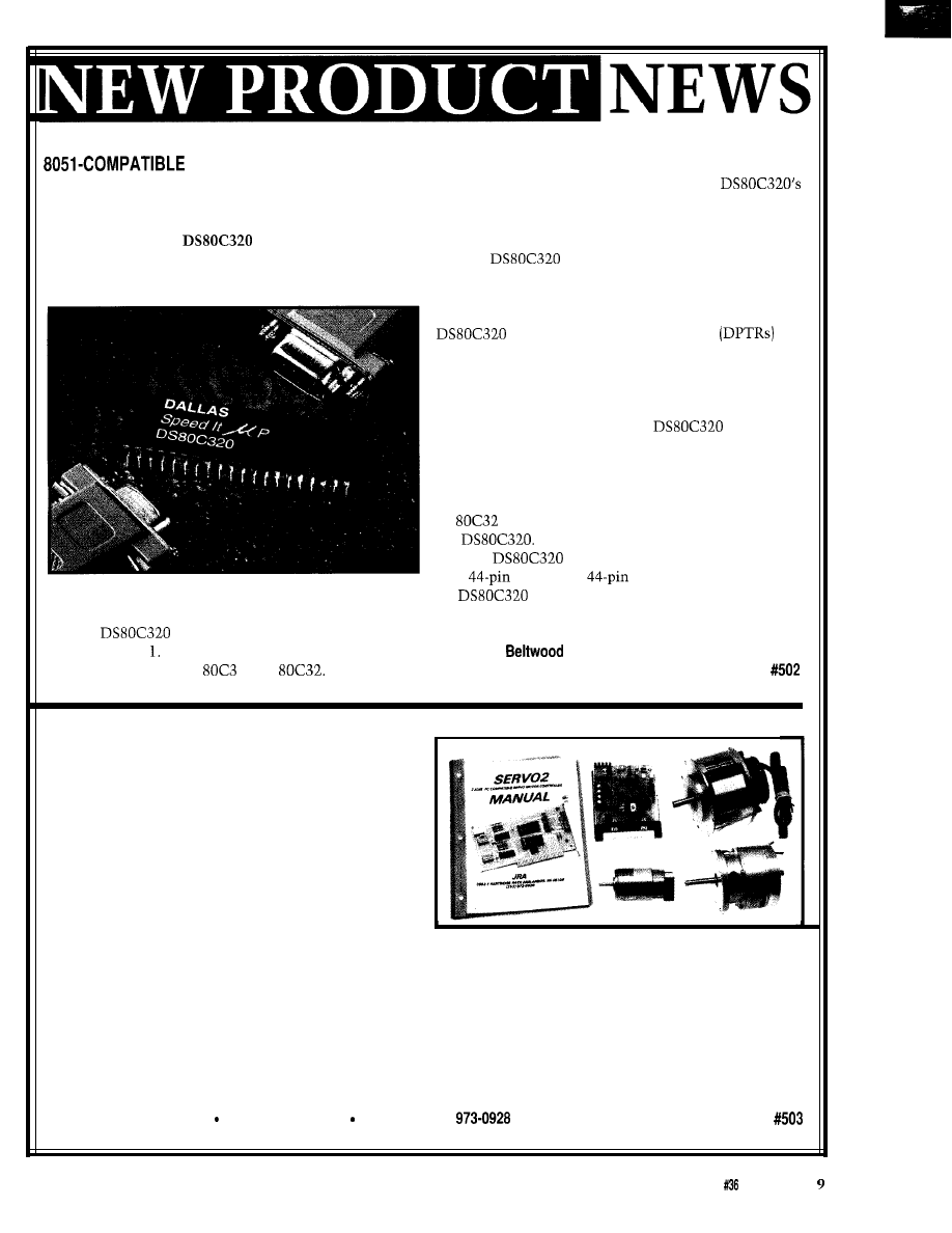
Dallas Semiconductor has announced a new
microcontroller that is a drop-in replacement for the
ubiquitous 8051. The
High-speed Micro runs
at clock speeds up to 25 MHz and over 6 MIPS through-
put. With the High-speed Micro, older designs can be
updated without changing processor architecture,
software, or development tools.
The
maintains full compatibility with
the original 805 It uses the same instruction set and is
pin-compatible with the
1 and
Any existing
software development tools, such as assemblers or
compilers, can still be used. In addition, the
internal timers can be run at their old speed, allowing
real-time software to function correctly when the chip is
dropped into an existing design.
The
provides several extras in addition
to greater speed. These include a second full hardware
serial port, seven additional interrupts, a programmable
watchdog timer, and power-fail interrupt and reset. The
also provides dual data pointers
to
speed block data memory moves. It can also adjust the
speed of off-chip data memory access to between two
and nine machine cycles for flexibility in selecting
memory and peripherals.
Like any CMOS product, the
draws less
power when run more slowly. Since it is more efficient
than a standard 805 1, it can do the same job running at
less than half the frequency. By simply changing the
crystal, a designer can reduce the power consumption of
an
design, with no loss in performance, by using
the
The
will be available in 40-pin plastic
DIP,
PLCC, and
PQFP. In large quantities,
the
DIP package sells for $6.50.
Dallas Semiconductor
4401 South
Pkwy.
l
Dallas, TX 75244
(214) 450-0448
l
Fax: (214) 450-0470
TWO-AXIS SERVO MOTOR CONTROLLER
A PC-compatible, two-axis servo motor controller
has been announced by JRA. The SERVO2 interface
plugs into any PC-compatible motherboard and provides
independent control over two motors. Feedback is
provided by an optical encoder on the motor shaft.
The controller operates in two modes. In position
mode, the user enters maximum motor speed in RPM
and final position in encoder counts. The motor shaft
will remain locked at this position until a new com-
mand is issued. In velocity mode, the user selects motor
speed and direction. In either mode, motor velocity may be changed during the move.
Using JRA motors, the SERVO2 will accurately control speed from 0 to 2700 RPM with a position resolution of
0.17”. Motor movement is smooth and vibration free throughout the velocity range. The system offers an affordable,
low-vibration replacement for stepping motor systems in XY positioning and robotic applications.
The SERVO2 software allows the user to read motor position or velocity in real time, run both motors simulta-
neously, create motion sequences by entering motor velocity and destination, plot position versus time, and teach
moves via the keyboard. The software is written in Quick Basic and program listings are provided.
The SERVO2 controller is priced at $350 with manual and software.
JRA
l
3602-l Partridge Path Ann Arbor, Ml 48108 Voice/fax: (313)
The Computer Applications Journal
Issue July
1993
ANALOG VOLTAGE MEASUREMENT VIA
PARALLEL PORT
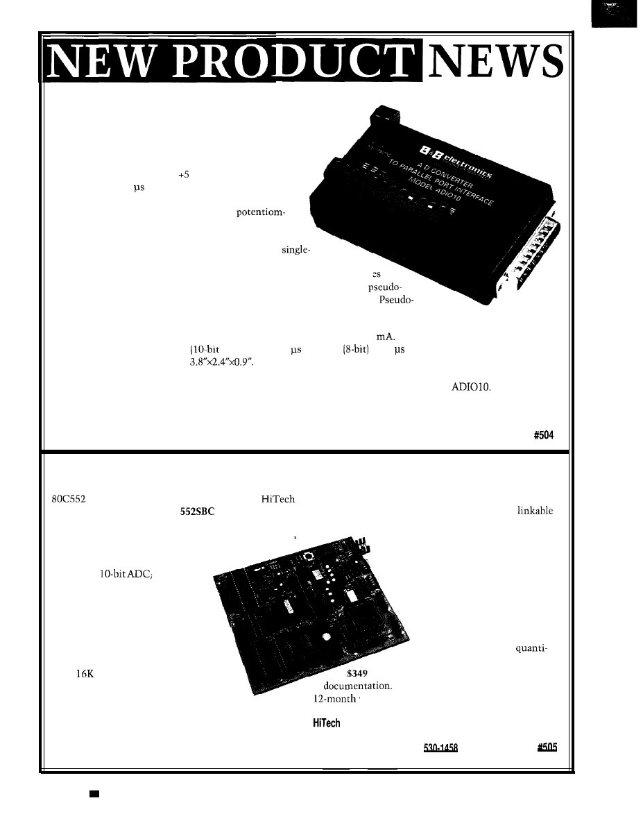
The AD1010 from B&B Electronics allows an IBM PC or
compatible computer to be connected to the outside world
using the computer’s parallel port. Its eight analog inputs
have a voltage range of -5 to VDC, with a conversion
time of less than 5 per channel. The speed, resolution,
and flexibility of this unit make the AD1010 ideal for
measuring voltages from lab experiments,
eters, sensors, and various other devices.
The AD1010 can operate in three different modes:
single-ended, differential, and pseudo-differential. In
ended mode, the eight input channels are converted with respect to a
reference. In differential mode, the inputs are grouped in pairs. The voltages
of the inputs are converted with respect to the other input of the pair. In
differential mode, all of the inputs are converted with respect to one input.
differential mode is helpful when there is a variable DC offset voltage applied to a group of
inputs.
The AD1010 requires a DC supply capable of providing IO-18 V at 50
It features a resolution of 10 bits plus
a sign bit. The conversion time
plus sign) is 4.4 max and
is 3.2 max. Reference output voltage
error is 2%. The unit measures
The AD1010 comes with an instruction manual and diskette containing demonstration programs written in
Quick Basic, Pascal, and C. The demonstration programs can be used to test or monitor the
The source
code for these programs is included on the diskette, and the routines can easily be modified for a specific application.
B&B Electronics Manufacturing Co.
4000 Baker Rd. P.O. Box 1040
l
Ottawa, IL 61350
l
(815) 434-0846
l
Fax: (815) 434-7094
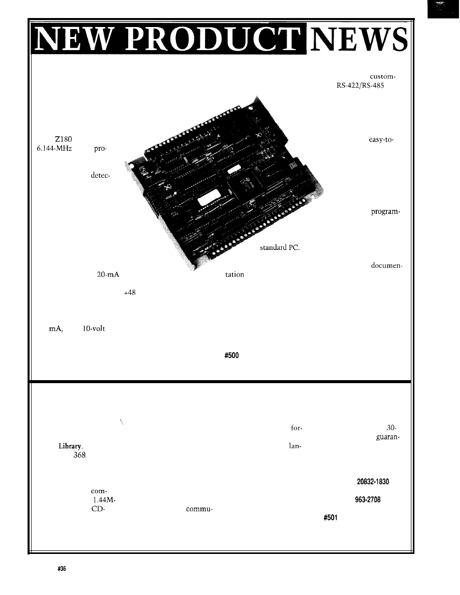
LOW-COST SINGLE-BOARD COMPUTER
The monitor on the development board allows the
A single-board computer based on the Signetics
designer to conveniently debug code in real time.
microcontroller has been announced by
Software drivers for keyboard scanning, LCD interface,
Equipment Corporation. The
is available in two
and serial port communication are available as
versions-a standard development board and an OEM
assembly language code modules.
board. The development board includes a 552SBC with a
The 552SBC can be used with an Apple
debug monitor and documentation.
Macintosh, or an IBM PC/AT [or 100%
The 552SBC board includes an
compatible) running DOS 2.0 or higher
8-channel,
two PWM
with a minimum of 5 12K bytes of
D/A outputs; 40 digital I/O lines;
RAM. Any standard communication
and three independent RS-232
package is required to download
outputs. Two of the serial ports
can be configured to use RS-422 or
RS-485 protocols by changing chips.
These peripherals are complemented
by a battery-backed, real-time clock and
up to
bits of EEPROM for storing
configuration information.
The four 28-pin JEDEC sockets have a
flexible GAL address decoding scheme. Two of the
sockets can be configured as bank-switched ROM areas
with simple GAL equation changes. One of the sockets
has battery back up ability through the DS1210 chip.
executable code.
The OEM version of the
552SBC single-board computer
sells for $149 in single
ties. The development version sells for
and includes the debug monitor and
Both products are backed with a full
warranty and unlimited technical support.
Equipment Corp.
9400 Activity Rd.
l
San Diego, CA 92126
(619) 566-1892
l
Fax: (619)
10
Issue
July 1993
The Computer Applications Journal
MOTION
CONTROL
DEVELOPER’S
KIT
The MC1400
Developer’s Kit
from Performance
Motion Devices
simplifies the task o
designing MC
based systems. The
MC1400 is a multiaxis,
DSP-based, motion control chip set that provides four
axes of servo control and includes advanced features
such as complex contouring, velocity feedforward, servo
filtering, and electronic gearing.
The MC1400 Developer’s Kit consists of an ISA-bus
compatible board and a software package that can
exercise all of the features of the MC1400. The kit can be
used as a platform to develop software for use with the
MC1400 chip set, or as a stand-alone MC1400 exerciser.
The PC board fits into a standard half-length board
slot and accepts four axes of incremental encoder inputs
with index pulses. Two types of motor drive signals are
provided: sign and magnitude outputs for use with PWM
amplifiers, and analog voltage signals for use with analog
amplifiers. The analog outputs are provided by on-board
D/A converters and are available with a
or a
volt range. A generic eight-bit input port is also provided.
The software package has an easy-to-use,
oriented interface. It provides direct low-level access to
all chip functions as well as convenient higher-level
routines to perform various integrated functions such as
trapezoidal moves and filter parameter changes. A
variety of C-source code libraries is also included.
Interfacing to external components is accomplished
through DB-15 and DB-25 connectors. With lo-volt D/A
converter output, the board requires an external
supply; with
D/A converter output, the board is
self-powered by the ISA bus.
The MC1400 Developer’s Kit sells for $1495. The
MC1400 chip set is available for $99 in quantities of 100.
Performance Motion Devices
11 Carriage Dr.
l
Chelmsford, MA 01824
(508) 256-l 913
l
Fax: (508)
Embedded System Developers
Y O U
U S E . . .
CV Tools
803861486
XRAY
CMICE
Spectra
68xxx
68xxx
Unlimited breakpoints and memory mapping
Trace file to record simulator session
Disassemblers
Then you need
The innovative
emulator that recognizes all of these.
Call us today at
(776-6423)
for your free information packet.
Automatic substitution of defined label names for all jumps
branches
Automatic insertion of supplied comments and expressions
Grammar Engine Inc.
921
Dr., Suite
122
Westerville, OH
4308 1
Fax
Broad range of processor
specific tools Intel.
RCA, Rockwell
All products require an IBM PC or compatible. MS DOS 2
greater
Same day shipment
VISA,
Express, and COD
technical
support
Thousands of
customers worldwide
716 Thimble Shoals Blvd.
Newport News,
VA 23606
(804) 873-1947
873-2154
Cross-Development
Tools
from $50.00
Cross Assemblers
Extensive arithmetic and logical operations
Powerful macro substitution capability
Unlimited include file capability
Selectable Intel hex or Motorola hex object file format
Simulators
Ten userdefinable screens
The Computer Applications Journal
issue
July 1993
11
LOGIC ANALYZER
A low-cost, software-based logic analyzer has been announced by F&J Associates. Logic Analyser gives an instant
picture of what is happening. Run it, set a viewpoint, then move around in memory. The clock handler or any
program in memory can then be observed.
Logic Analyser supports all Intel
up to and including the i486, and disassembles code which contains
standard and protected mode instructions. All orthogonal
address modes and all floating point instructions are
supported, including i486 embedded instructions. Code can be displayed in any combination of
and
address and operand sizes.
Logic Analyser’s general probe design allows generic events to be specified in Breakpoint, Tracepoint, and
Watchpoint commands. Logic Analyser uses debug hardware built into ‘386 and i486 processors to allow specifica-
tion of memory access breaks, input or output tracing, and interrupt watching. When all hard breaks are used, soft
breaks take over-there is no limit to the number that can be defined or set.
Standard debugging is also supported, so when a problem occurs, it can be readily solved. Breakpoints can be set,
and step or step over commands can be used to allow incremental execution. Event capture can be enabled and the
resulting history played back. Registers, stack, and data displays are format selectable in
and
forms.
Logic Analyser features overlapped or tiled windows to give full control of screen display. Logic Analyser also
features a Clone key which allows any window to be instantly cloned. This allows the ability to set up one or more
alternate viewers, tracers, logic analyzers, or symbol tables. Most tools are
and can be assigned to different
process threads data structures, or any object of interest.
Logic Analyser requires MS-DOS 3.1 or later, a standard 640K base memory or 1 MB of extended memory. It runs
with any IBM PC/XT, AT,
or compatible with 8086, 80286, 80386, or i486 CPU. Logic Analyser sells for $199.
F&J Associates P.O. Box 62539
l
Scarborough, Ontario
l
Canada
Ml
l
(416) 438-2720
l
Fax: (416)
The new high-performance software analyzer that
captures, time-stamps, and records software and
interrupts, DOS calls, BIOS interrupts, and user-defined
events in real-time for analysis of race conditions,
interrupt activity, and service times.
gives you
the hard facts you need to fix the big one that stands
between system test and shipping your product.
DOS
BIOS
INT
Oeh
Interrupt
0100
0200
0300
0400
0500
0600
0700
oioo
Figure 1.
timestamping of C library
function call.
If
can break-down a library function call into
its components (above), imagine how you’ll see context
switches, device interrupts, and other asynchronous code
Call
for free technical
GENERAL
Tel 206.391.4285
SOFTWARE
Fox 206.557.0736
Box
2571, Redmond, WA 98073
BBS
All
the
of General
We offer a full line of low cost
embedded
controllers and software tools which are ideal for
developing products, test fixtures and prototypes.
Features Include:
Low power
CMOS
design
Up to 60K of code space and up to 60K of data space
5 to
15 volt
operation
Small form factor (3.5” 6.5”) with prototyping area
System
diskette includes application notes
Start at $100
Available Options:
Multifunction Board adds A/D, 24
lines and more!
BASIC-52 or Monitor/Debugger in
C Compiler $100 or BASIC Compiler for $300
Iota Systems, Inc.
POB 8987
l
Incline Village, NV 89452
PH:
l
FAX: 702 831-4629
Issue
July 1993
The Computer Applications Journal
PRINTER TESTER
A device that tests
and troubleshoots
standard parallel inter-
faces and dot matrix and
daisy wheel printers has
been announced by Sibex
Inc. The LP-1 Printer
Tester
performs two
basic series of tests that
are designed to test the
communication and data
transfer capability
between the devices. A
built-in microprocessor
allows the
LP-1
to test
printers, cables, and
interface boxes without
the need for a computer.
The LP- 1 verifies
that the printer is
receiving the correct
parallel data or com-
mands from the computer,
as well as verification that
the printer is issuing the
proper commands to the
computer.
The Printer Tester
attaches in-line between the
printer and computer and
performs two series of tests.
It monitors the communica-
tion between the computer
and the printer. The LP-1
displays (on
the line
status and pulses as they
change. High-speed signals
and pulses are latched or
stretched to make them
easily readable for trouble-
shooting. This test verifies
proper operation of the
computer interface, inter-
connect cabling, and the
printer output.
The second sequence
tests the printer’s ability to
generate text if it receives
the correct instructions.
The LP- 1 Printer Tester
incorporates a microproces-
sor which has been pro-
grammed to simulate a
computer output. In this
mode,
the LP-1 causes the
printer to initially print
each character in the
alphabet and then print two
lines of preprogrammed
text. The test sequence will
repeat continuously until
stopped. This repeat tests
for intermittent problems
and provides sufficient time
for analysis of the pulsing
signals.
The LP-1 is housed in a
hand sized plastic case and
comes with male and
female DB-25 connec-
tors. An external
110
VAC power supply and
detailed instruction
manual are provided
with each unit. The LP-1
sells for $249.
Sibex, inc.
1040 Harbor Lake Dr.
Safety Harbor, FL 34695
(813) 726-4343
Fax: (813) 726-4434
Technology
Solutron is a complete
network
that supports the 6051,
and
The
full
advantage of multiprocessor
modes built into
ports.
Our flexible software and
hardware allow devalopers to
vet
inexpensive master/slave
embedded controller
l
Up
to nodes
l
CRC error checking with
network overhead and low
card fa
code in
the PC
documentation
120 West State Street,
NY
273.5715 273.5712
l
New C Programmable miniature controller
l
Seven 1 O-bit analog inputs
l
Seven digital inputs
l
1 O-bit DAC: voltage or current output
l
Twelve digital/relay driver outputs
.
serial ports
. Enclosure with LCD/Keypad available
l
Expansion bus for additional, low cost
l
Easy to use Dynamic
development software
only
Z-World Engineering
1724
Picasso Ave., Davis, CA 95616
(916) 757-3737
Fax: (916)
24 hr. Information Service: (916) 753-0618
(Call from your fax and request data sheet
The Computer Applications Journal
Issue
July 1993
1 3
FEATURES
Object-oriented
Programming in
Embedded Systems
Mike Podanoffsky
PC Parent-Child
Programming: a Path to
Multitasking Under DOS
Object-oriented Programming
in Embedded Systems
High-speed Modem
Basics: the Working
Hardware
programming is
more than just the
newest technical jargon.
It is a well-organized way of viewing
programming which delivers, by my
criteria, the ability to break down
complex problems into smaller, more
manageable solutions.
Object-oriented programming
(OOP) is a programming concept. It is
an approach intended to clarify the
way you think about a problem.
Because of this, you can use
oriented concepts with any computer
language including C, assembler, or
BASIC. The OOP paradigm is not
limited to just languages like C++ or
Smalltalk, which have devoted
themselves to object construction
techniques.
Object-oriented code provides
some of the clearest, most modular,
and easiest-to-test code you’ll write.
provides this because of the way
in which the code is organized from
the start. As you read what OOP is
really all about, you’ll discover that
you may have already used some
object-oriented concepts before
without knowing it.
For most programmers, OOP
begins to work for them when they
begin to actually get a handle on the
code itself. 1’11 try to demonstrate OOP
14
Issue
July 1993
The Computer Applications Journal
int
Message
switch Message
case HANG-UP:
break:
case PHONE-ANSWER:
break:
Figure l--The behavior of the Greeting tape object is
encapsulated within fhe Greeting module.
concepts and ideas by explaining some
of the key concepts in terms of objects
(no pun intended) in the real world and
by developing an XMODEM program.
OBJECTS
method.
In OOP, you describe your
program in terms of objects. Objects
represent real-world components
which interact with each other. For
example, a
CAR
object moves about on
HIGHWAY
objects and strikes
T R E E
objects. In OOP-speak, the behavior an
object exhibits is called the object’s
Take, for example, a telephone
answering machine. The objects in
this system are the incoming phone
line, the greeting tape, the message
recording and playback tape, and each
of the buttons that a user may press to
activate replay, rewind, and so forth.
Basically, anything that has a behavior
that must be modeled must be
represented as an object.
The
I N C O M I N G
-
P H O N E
-
LINE
object
detects the ring signal, answers the
phone, senses voice, and detects
hangup. The
G R E E T I N G
-
TAPE
object
models the behavioral requirements of
the greeting tape; namely, recording
and playing back an announcement.
Objects communicate with each
other by sending and receiving mes-
sages. The messages objects send to
each other can consist of anything, the
only limitation being their content
must meet the specific requirements
of your application. You can see how
messages can be coded in Figure
1,
which shows a simplified object
routine for handling the processing of a
phone greeting.
P H O N E
-
LINE
object detects the ring
In the telephone answering
machine example, when the
typedef
int fof:
int id;
int x, y;
int altitude:
int speed;
int x-heading;
int y-heading;
int z-heading;
friend or foe status
plane's id for future ref.
current location in grid
x, y, and headings
Plane:
Plane friend, foe:
two planes
int Flight int message, Plane far * plane
switch message
case UP:
++plane->z_heading;
case DOWN:
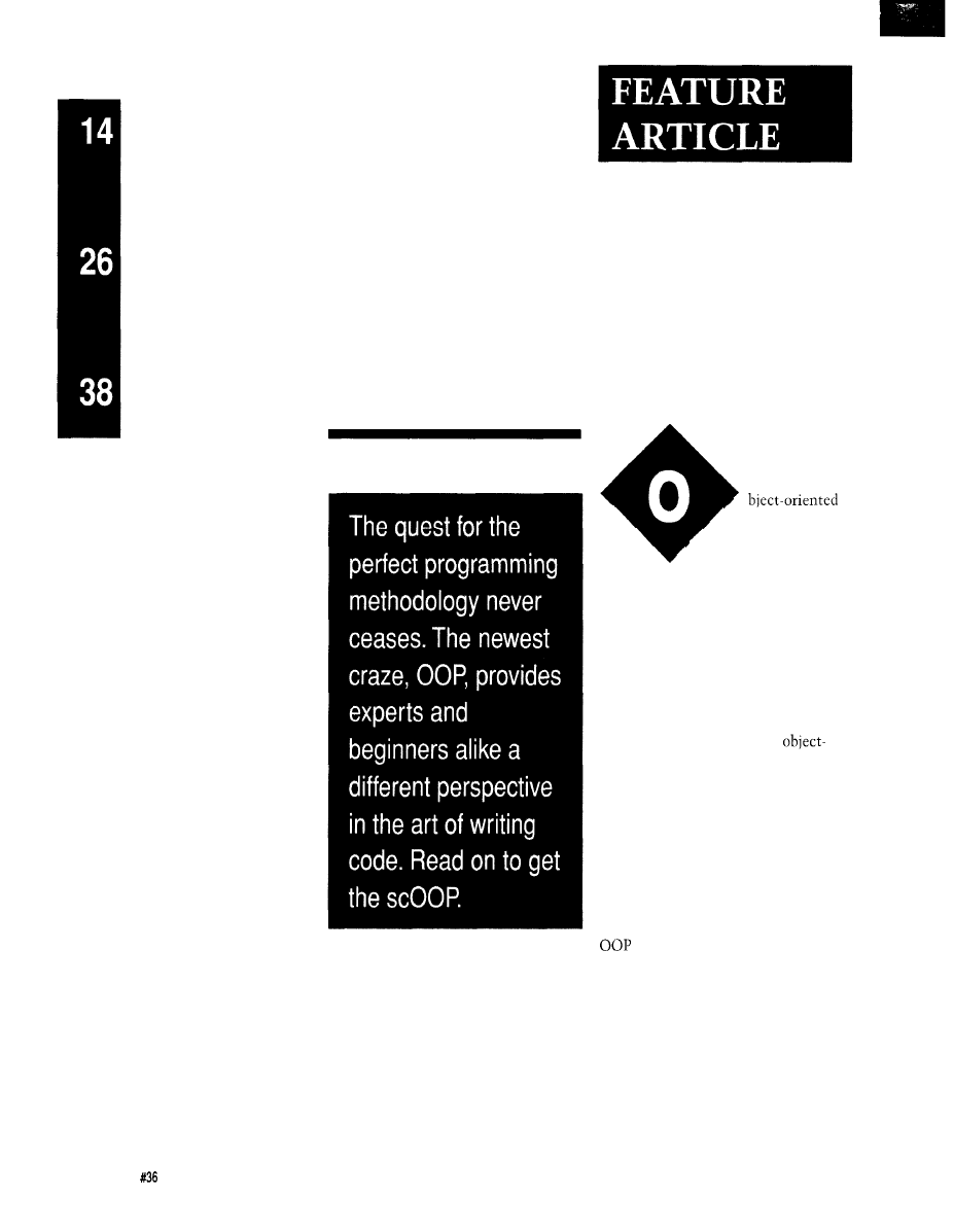
Figure 2-I he
message
for
this hypothetical
Simulator example
demonstrates OOP
principles.
signal and answers the phone, it sends
a “Play Greeting Tape” message to the
G R E E T I N G
-
TAPE
object. In turn, the
GREETING
-
TAPE
object sends a message to
the
R E C O R D
-
TAPE
object to begin
recording.
If, at any time during these
processes, the
I N C O M I N G
-
P H O N E
-
L I N E
object detects a hangup, it sends the
“hang up” message to all objects,
which perform cleanup behavior
appropriate to each of their methods.
The
G R E E T I N G
-
TAPE
object rewinds the
greeting tape and the
RECORD
-
T A P E
object stops the recording. Every object
resets itself for the next message
instance.
While objects may communicate
with each other, they must not
interfere with each other’s internal
processes or structures. Therefore,
objects cannot change variables in data
structures or set global modes. An
object’s method is totally self con-
tained. You may, however, set vari-
ables and send them as a message to an
object.
This tenet is essential and an
important consideration in designing
true object-oriented systems. It is
important that an object and its
behavior be totally encapsulated.
All too often in traditional
programming, there has been a
tendency to develop a single routine
that behaves slightly differently
because of modes or states. OOP tries
to avoid this by developing objects
with a single and distinct behavior,
which means the message carries
modal or state-specific information for
which the object will have a single
response. Of course, you are still free
to break this rule and make your code
just as complex and as difficult to
understand as before. I can lead you to
the river, but I cannot make you drink,
as the saying goes.
WHERE’S THE BENEFIT?
How is the OOP model more
efficient than other programming
paradigms? The functionality of the
answering-machine objects is delin-
eated by function, that is, specific
objects handle specific functions.
There is no behavior in the answering
machine system that is not defined in
The Computer Applications Journal
Issue
July 1993
15
some object. This differentiation leads
to cleaner code than code produced
using top-down design methods,
because to locate and correct any
problems in the system, you isolate
the problem to the object responsible
for that process and correct its behav-
ior or method. To test or debug an
object, you send it a message with
consistent content, and you are done
when the object returns the correct
response to that message.
The system created by your code
becomes more functional when there
is an introduction of a new object in
the system. There should not be
substantial changes in any existing
objects (if they are truly encapsulated)
since they and their message struc-
tures are not changed by the addition
of the new object. The only thing that
may change is the order of messages
flowing through the program, or the
addition of other valid message types.
other words, just add the behavior of
the new object, define where and when
messages should be sent to it, and how
it responds to the calling object.
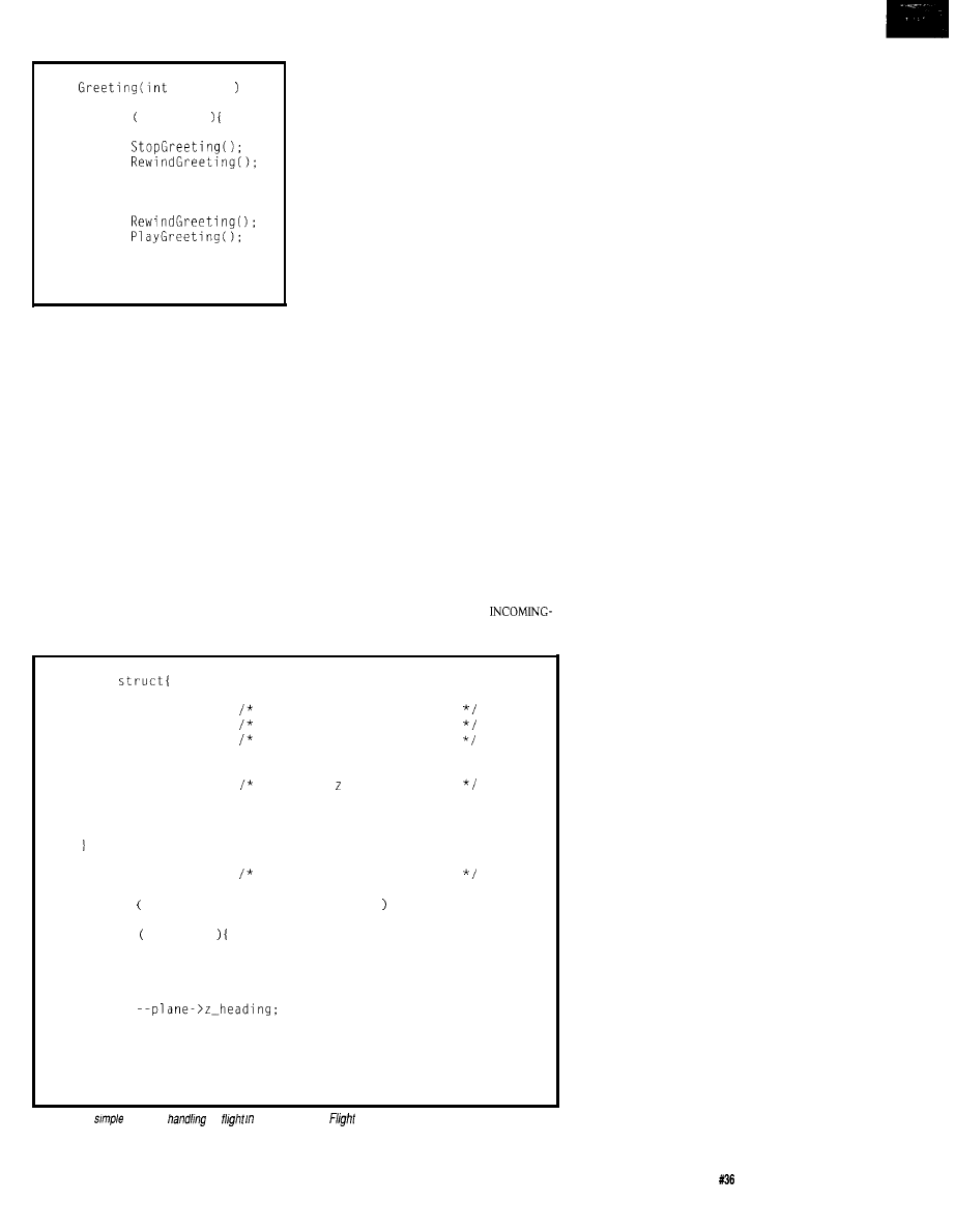
Listing l--Two objects make up
data transfer program, one for reading and processing the
file
and the other for performing serial data
The Xmodem Protocol:
SENDER
command issued to send file
RECEIVER
(sender may send any text to
receiver including file size,
expected time to transmit,
or other info
command issued to
receive file
NAK
SOH 01 FE
CKSUM
->
ACK
SOH 02
CKSUM
ACK
SOH 03
CKSUM
ACK
EOT
ACK
#include
#include
#include
enum
(continued)
We’re
Powerful,
And We’re
4
.
2
serial
ports
3
programmable parallel
RAM/ROM capable
powerfail detect interrupt
and reset
counter-timers
watch dog timer
expansion connector
Cheaper.
In fact, you’ll get the best product for about
half the price. If you’re interested in getting the
most out of your project, put the most into it.
For the least amount of money.
Call us today for complete data sheets, CPU
options, prices and availability.
Work
Welcome. Call or fax for
complete data sheets
2308 East
Sixth Street
SD 57006
Phone (605)
8521
(605)
8109
S
M A L L
B
U T
W
E
’
R E
P
O
W
E
HARDWARE
Checkoutourcompleteline of DSP boards based on powerful
floating-point processors like the AT&T
(25
and the Analog Devices ADSP-21020 (75
Several
analog interface modules are available. DSP boards start at just
SOFTWARE
W e have everything you need to do DSP software
development, including C compilers, assemblers, source-level
debuggers, algorithm development tools, and many example
programs. Data can be transferred between the DSP board and
host at up to 3
with the host interface library (source
code included).
SOLUTIONS
Call our friendly, knowledgeable staff to discuss your
applications and we’ll show you how easy it is to take
advantage of DSP technology.
800-848-0436
Real- Time Multitasking with DOS
for Microsoft C, Borland C, Borland/Turbo Pascal
Develop Real-Time Multitasking Applications under MS-DOSwith
is a
high-performance real-time multitasking kernel. It runs under MS-DOS and supports
Microsoft C, Borland
Pascal, and Stony Brook Pascal+.
you can link to your
application. It lets you run several C functions or Pascal procedures
tasks.
offers the following
advanced features:
event-/
Novell’s IPX services
0, DR-DOS,
(1
several tasks
re-entrance problems
and message-passing
harddisk, andfloppydiskidlettmes
usable byothertasks
interrupt handlers for keyboard, COM
(MSC
1.012.013.x) $495
$ 4 4 5
handling
banktransfer,
32
Hamburg
G e r m a n y
Professional Programming Tools
Phone
100140,633
is the
complete
ROM
development software tool
It
you run Microsoft. and Borland and C++ programs on an
embedded 80x86 CPU without
DOS or a BIOS.
you money. There are no DOS or
BIOS royalties
to Pay
for
your embedded systems.
is complete! It
includes the following and much more:
*Supports Borland’s Turbo Debugger.
*Remote Code View style source level debugger.
l
ROMable startup code brings CPU up from cold boot.
l
ROMable library in source code.
*Flexible 80x86 Locator.
PACKAGE
$435. 3-Y
GACK GUARANTEE.
What
ROM Your Borland or Microsoft
Changing the method-the code
that executes and thereby creates an
object’s behavior-should have less
impact on the overall program because
the code for an object is localized.
However, changing the messages an
object produces could have a serious
ripple effect since other objects would
have to be changed to understand how
to respond to the new message type.
Consider the telephone answering
machine example that I outlined
above. To implement a toll-call
savings feature where a machine
allows two rings if there are messages
waiting, but won’t answer for four
rings when there aren’t any messages
waiting (to save you money when you
call in for your messages] changes the
method of the
I N C O M I N G
-
P H O N E
-
L I N E
object, and only that object. As long as
the messages flowing in and out of the
I N C O M I N G
-
P H O N E
-
LINE
object do not
change, this should be the only object
requiring any changes.
You can legitimately claim that
OOP itself doesn’t bring any advan-
tages that a well-structured program
wouldn’t have provided. Still, OOP
forces you to naturally develop a
delineated, concretely defined messag-
ing protocol and interobject interface
structure.
OOP is designed to create objects
once so you can reuse them in many
different programs, not unlike a
programming library. For example,
once you’ve developed a communica-
tions object, potentially you may reuse
it repeatedly just by sending it mes-
sages.
OBJECT DATABASE
I once wrote a database system
that stored documents that contained
both text and images. The entire
database access was an object. The
interface to the database was either a
“Store Element” or a “Retrieve
Element” message together with a
pointer to an element, which was
either some text or an image.
The database itself was considered
the object which responded to store or
retrieve messages. The method used by
the
DATABASE
object to store elements
was fully encapsulated within
DATABASE
object.
18
Issue
July 1993
The Computer Applications Journal
Listing
l-continued
INITIALIZE =
CONNECT,
TRANSFER,
DISCONNECT.
CANCEL,
ASCII = 0,
XMODEM = 1,
= 0,
ERR_BADMESSAGE = 1
ERR_CANTCONNECT,
ERR-TIMEOUT,
typedef
int
file;
char far *filename:
char far *telephone:
char far *buffer;
int
bufferlen;
int
int
int
parity:
int
int
#define
(void far
+ (unsigned
#define
(*Time (long)(t) (long)(p)*18
static int maxerrorcount = 0:
static long far * far Time =
CONTROL-Z
#define OVERWRITE
#define MAXERRORS
#define OVRWRITIM
#define BLOCKSIZE
#define
TIMEOUT
#define SLEEP
26 control z
1
define for normal overwrite
10 max number of times to retry one block*/
10 time to pause (none if OVERWRITE)
1'28 transmission block size
80 timeout time in send
99
30 timeout time in
Protocol characters used
#define SOH
0x01
Start Of Header
STX
0x02
Start Of Text
EOT
0x04
End Of Transmission
#define ACK
0x06
#define NAK
0x15
Negative
#define CAN
0x18
Cancel
#define DEBUG 1
Prototypes
char
port);
int
port, char
INTERFACE
(CONNECTS TO
of
switches,
and other
and
Provides 32 status
isolators
separately).
TEMPERATURE
$49.95
FULL TECHNICAL
the
hone by our staff. EACH ORDER INCLUDES A
IN
BASIC, AND
LANGUAGE. A detailed
reference manual is also
for
continuous
24
hour industrial applications. All
Tandy. A
most
RS-232 or
Mac and
All standard baud rates and
may
19,200 baud).
our
to
FREE
PACKET. Technical Information (614)
24 HOUR
ORDER LINE
CONTROL, INC.
Suite
43215
Applications Journal
Issue July 1993
19
When I first implemented the
DATABASE
object, I didn’t have time to
write a complete database code with
indexing. I just needed to save objects
for subsequent retrieval. Initially, each
store message just created a DOS file
where the object, text, or image was
stored. Eventually, I went back and
changed the
DATABASE
object to a fully
functioning database. But the message
interface remained the same. Ah, the
beauty of fully encapsulated objects!
FLIGHT SIMULATOR
Let's
continue our look at what
constitutes objects and messages.
Flight simulation is as interesting to
me as flight itself. A decent flight
simulation shows various views from
the cockpit and flight instruments
such as altimeters, compasses, fuel
gauges, flaps, and so forth. To write a
good object-oriented flight simulator,
each instrument gauge has to be a
clearly defined and independent object.
Each object, of course, will have to
have its own behavior.
One object is the plane itself. As
the
PLANE
object “flies,” it updates its
position represented as three coordi-
nates, x, y, and z (height), based on its
“speed” and rate of ascent. The
PLANE
object receives several messages from a
variety of sources. It receives wind and
turbulence information, periodic time
information to update its position, and
keyboard messages. The person using
the keyboard acts as the pilot and
would use the keyboard to tilt the
plane left or right or pull the nose up
or down. These keyboard actions are
passed to the plane object as messages
to direct the flight path.
The instruments and gauges need
to represent the current state of the
flight. The
PLANE
object sends an
“update” message to all instruments
and controls. In turn, they each update
the graphical representations of their
instruments. Each instrument or gauge
has a different method and representa-
tion, but they all respond to the same
“update” message. Figure 2 shows a
trivial skeleton for a Flight Simulator.
It is meant to demonstrate OOP
principles.
Polymorphism is the term used to
describe the situation when different
Listing
l-continued
int
int port, char far string);
int
int port, char far buffer, int bufferlen);
int
DataCommControl far * DataComm):
int
Message, DataCommControl far * DataComm);
int
Message, DataCommControl far * DataComm):
int
argv, char far * far
DataCommControl far
char
port)
return NAK;
int
port, char
return ERR_NOERRORS;
int
port, char far * string)
int Err = ERR_NOERRORS:
while (*string)
if ((Err =
*string++)) ERR_NOERRORS)
break;
return Err:
int
port, char far * buffer, int
int Err =
while (bufferlen- >
if ((Err =
*buffer++)) !=
break;
return Err:
int
far * DataComm)
DataComm);
return ERR-TIMEOUT;
int
Message, DataCommControl far DataComm)
int Err = ERR_BADMESSAGE;
int port =
switch (Message)
case INITIALIZE:
return ERR_NOERRORS;
case CONNECT:
Err = sendstring (port, DataComm
if
.
!= CONNECT
Err =
break;
case TRANSFER:
Err =
break;
case CANCEL:
CAN);
break;
case DISCONNECT:
Err =
break:
return Err;
int
Message, DataCommControl far * DataComm)
20
July1993
The Computer Applications Journal
Listing l-continued
int i;
int Err = ERR_BADMESSAGE;
int port =
int errorcount = 0;
char
+ 128 + 11;
switch (Message)
case XMODEM:
if
==
int blocknumber =
int NotEndOfFile = TRUE:
long timeout;
char checksum;
int retry:
char far * readbuffer =
char ch;
errorcount = 0;
wait for initial NAK
timeout = *Time;
while (TRUE)
if
80 seconds max
return ERR-TIMEOUT;
ch =
if
== CAN)
return
if
== NAK)
break:
send data blocks
while
= SOH:
= blocknumber;
= -blocknumber;
NotEndOfFile =
readbuffer, BLOCKSIZE) ==
for = 0; i < BLOCKSIZE:
checksum +=
+
11 =
checksum:
= buffer:
=
retry = TRUE;
while (retry)
Err =
retry = FALSE:
if (Err !=
return Err:
timeout = *Time:
while (TRUE)
if
10 seconds max
return
ch =
if
== CAN)
return
(continued)
(multiple) objects respond differently
to the same message. The word comes
from the Greek “poly” for multiple
and “morphism” for change. Another
example of a polymorphism is in
graphical applications such as
When an object is resized,
the object is sent a “resize” message.
Each object responds to the same
message but in different ways because
a rectangle resizes and draws differ-
ently than a circle or a picture.
OOP IN DISTRIBUTED SYSTEMS
Distributed systems are especially
well suited for OOP techniques
because, by their very nature, distrib-
uted systems are message-based
systems. Distributed systems use
messages that are not unlike messages
passed between objects. A medical
equipment monitor system is one
example of a distributed system. One
machine is situated by a patient,
monitoring several vital signs while
another part of the system is at the
nurse’s station. They not only commu-
nicate with each other, but a failure to
receive periodic update information is
a signal to the nurse that the equip-
ment (or connection) may be faulty.
With an OOP design, the patient
monitor doesn’t care where it sends
messages. That is, it should be un-
aware of whether its messages are sent
between two object modules or
between machines physically dispar-
ate. Instead, it just treats the nurse’s
station as an object that it sends
messages to. In the early development
of the product, or during debugging,
there need not be physically a re-
motely connected nurse’s
only an object to receive and send
messages.
As the development evolves into
two physically separate (distributed)
systems, the method of the
STATION
object (which formerly was a
device or program that only emulated
the nurse’s station) evolves into a
featured component that communi-
cates with the monitoring station.
Furthermore, to make the system even
more modular, create the monitoring
station using two objects: a
T O
-
N U R S E
'
SSTATION
objectanda
M O N I
-
T O R
-
PATIENT
-
STATION
object.
The Computer Applications Journal
1 9 9 3 2 1
When distributing the objects, the
dynamics of the system change. Not
all debugging and performance issues
are resolved. For example, there are
now connect time, data communica-
tion performance, speed of data
transfer, and loss of data connection
issues introduced when physical data
communications is introduced. OOP
does not eliminate these physical
concerns.
INHERITANCE
One final OOP-speak term,
inheritance, refers to an object inherit-
ing the behavior [and messages) of
another object that is already defined.
This is a very commonly used tech-
nique within OOP programs and you
will no doubt use it where appropriate
even if you didn’t know the technique
had a name.
For example, suppose that several
buttons in a given problem behave in
exactly the same manner: when
pressed they will click and continue to
repeat the click until released. As each
button is held down, it increments or
decrements the value in a variable it
controls. For example, the volume or
channel control buttons on a televi-
sion remote control.
Now suppose you needed a button
that exhibits this kind of behavior, but
must also perform other functions.
One example might be a color-select
button which must change hue or
contrast.
Your obvious choice is to create a
HUE
object in which you perform any
color change in response to the button
being down. The
HUE
object sends or
receives messages from its
object that handles the tasks common
to all buttons. In this example the
HUE
BUTTON
inherits the behavior common
to all general buttons.
OBJECT-ORIENTED APPROACH
TO DATA COMMUNICATIONS
The original intent of this article
was to create an XMODEM data
transfer program using object-oriented
principles. The XMODEM data
transfer program should be given a
message that contains a telephone
number, a communication port’s
address, and a data file. The data
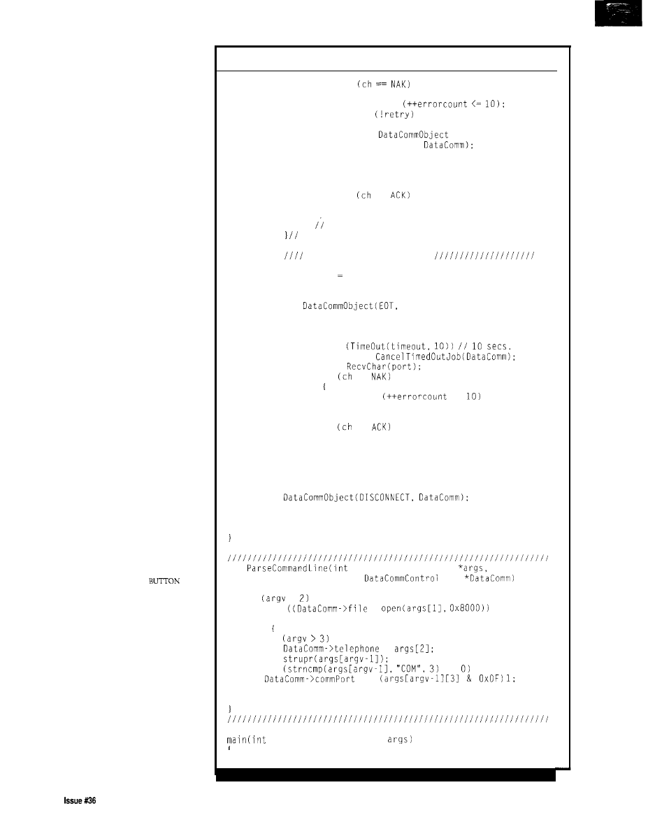
Listing l-continued
if
retry =
if
(CANCEL,
return Err:
break:
if
==
break:
t while retry
while not end of file.
send End Of Transmission
retry = 0;
errorcount 0:
while (retry)
DataComm);
timeout = *Time;
while (TRUE)
if
max
return
ch =
if
==
retry =
<=
break:
if
==
break:
break:
case DISCONNECT:
break;
return Err:
int
argv, char far * far
far
if
< return FALSE;
else if
=
== NULL)
return FALSE:
else
if
=
if
==
=
return TRUE:
argv, char far * far *
(continued)
22
July1993
The Computer Applications Journal
transfer then occurs unattended-but
not in the background.
The XMODEM protocol has been
around for over a decade and was
invented in order to transfer files
between computer systems over phone
lines. It was developed to overcome
some of the problems inherent with
data transfers that used modems such
as dropped bits, random characters
injected in the data stream through
noise, bursts of errors, and so forth.
Under the XMODEM protocol, a
file is transferred in blocks of 128
bytes preceded by a header and
followed by a checksum byte. Once
the block is sent, the program waits for
a return acknowledgment that the
block was received. If a Negative
Acknowledgment is returned, the
sender will retransmit the block.
The XMODEM protocol isn’t very
fast, nor is it absolutely error free. The
checksum is sufficiently small so
that, statistically speaking, errors can
occur in the data stream that will
“fool” the checksum algorithm. The
protocol is slow because the latency
time waiting for an acknowledgment
is a large percentage of the
block being transmitted.
WHAT ARE THE OBJECTS IN
DATA COMMUNICATIONS?
If this were rocket science it
would have been easy to visualize and
model real-world components. We
have a harder time, however, when we
cannot touch and feel the objects.
Recall that an object has to have and
exhibit a specific behavior and it
should be able to respond to and/or
send messages.
For our purposes, I’ll implement
the XMODEM data transfer program
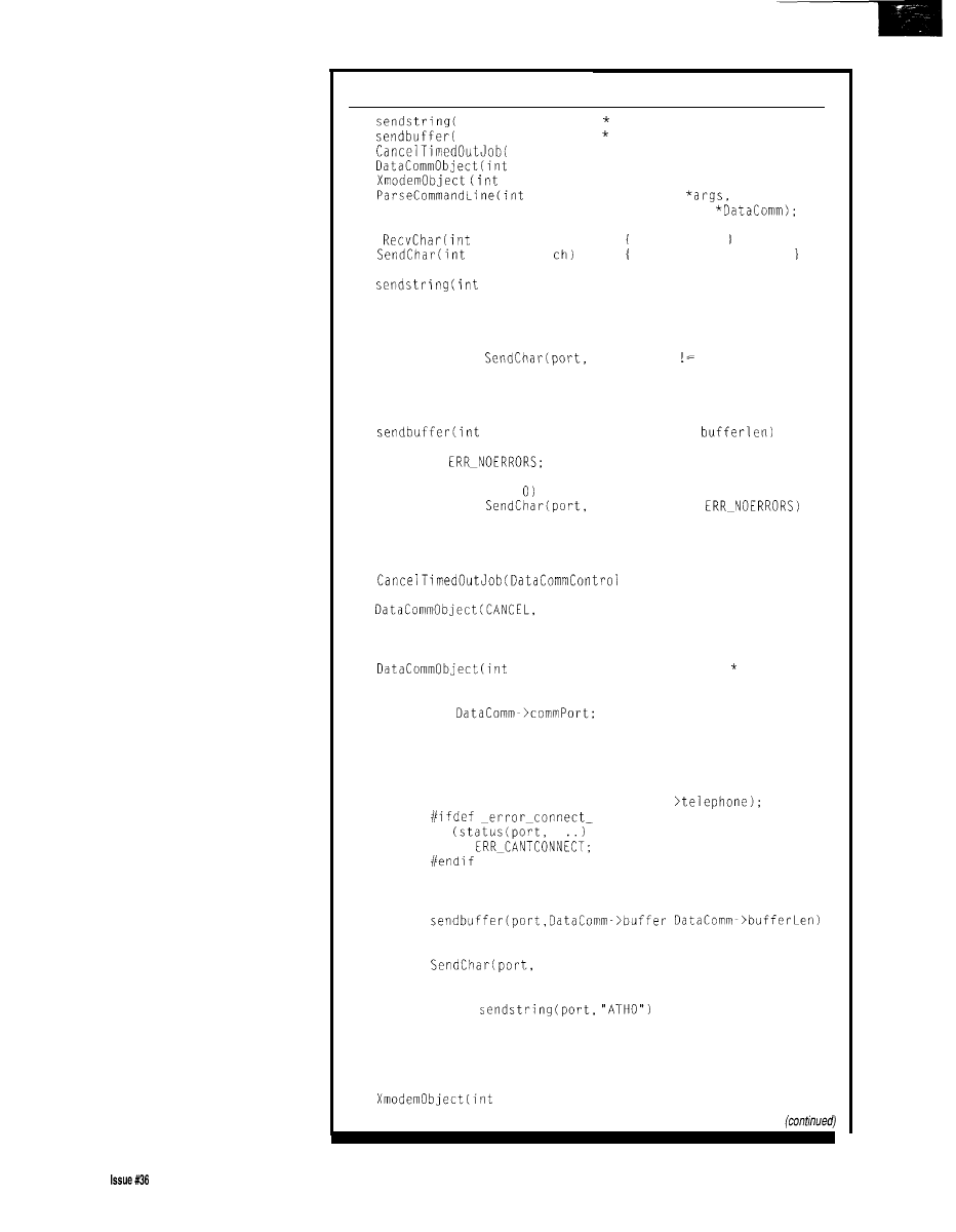
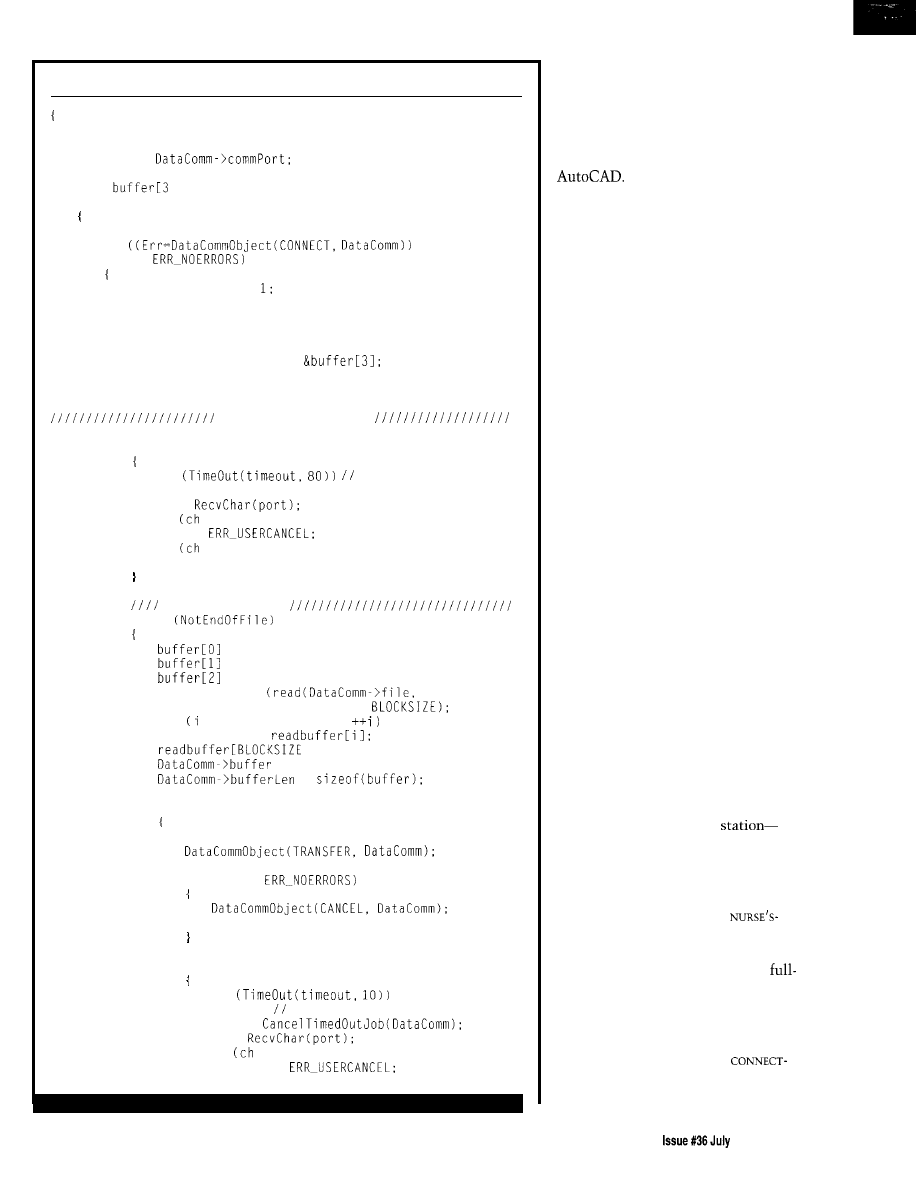
(Listing 1) as two objects. One object,
the
XMODEM
object, will read and
process the file. The other object, the
DATA COMM
object, will perform the
actual serial data communications. I’ll
refer to these objects as the
O b j e c t
a n d t h e
D a t a C o m m O b j e c t ,
respectively.
I’ll have to define each message
that will pass between these two
objects as well as their expected data.
The
XmodemObject
will receive a
message that is a command to transfer
Listing
l-continued
int
= 0;
Send Object-oriented
if
args,
Sx filename
Rx filename
t
I
else
file to on Com%c.\n",
? DataComm.telephone
phone>",
DISCONNECT,
a
file through a specified
port.
and finally to terminate the
T h e
X m o d e m O b j e c t
w i l l p a s s a
tion with a hangup message.
command message to the
Da t a Comm
further defined the interface to
Object
that will cause the
D a t a
t h e D a t a C o m m O b j e c t a s a n i n t
to
make a connection,
(integer value) followed by a
f a r
send individual XMODEM packets,
pointer to
da t a, as
shown below:
Only $85 1 for
The world’s most
emulator for members of the
8051 family is incredibly affordable.
unique
Advanced Emulation Technology
potent pending) delivers
the best possible emulator
for engineers, consultants and
students.
AET is o revolutionary design architecture that provides more
features with 75% fewer components, smaller board space and
lower cost. Emulator and probe electronics are integroted in a
single package only 3” by 4”.
Metatink also delivers leading-edge customer service, including
a 30
money back guarantee, 10 day trial for qualified
customers, rental plons and free technical support.
40MHZOperotion
SUPPORTS
64K
Emulotion Code Memory
SUPPORTS
64K
Memory
Windowed
User
Any PC
Cross Assembler
(View While Executing)
Built-In Self-Test
today for FREE
DISK!
(800)
(800) 63
PO. Box 1329
Chandler, 85244-l 329
Phone
9260797
926-l 198
The Computer Applications Journal
Issue
July
1993
2 3
int DataCommObject
Message,
v o i d f a r * D a t a ) :
This is a convenient way to pass both
a command and data.
ERROR REPORTING
Finally, I need to cover the issue of
error messages. If the Data C omm
0
b j e c t cannot make the connection
because the
port address is
wrong, or the data
parameters
don’t match the port’s capabilities, or
the phone will not connect, then it
should generate a message indicating
an error. This message should be
reported back to the object that
i n v o k e d t h e
D a t a C o m m O b j e c t .
pass these errors back in the
function return value directly. This is
by far the easiest and most cost
effective method and is used in the
code provided with this article.
SUMMARY
I have been using OOP techniques
whenever I can. I find I can better
organize the functionality of my code
by using the OOP paradigm. A careful
study of the code in Listing 1 should
give you a better idea of how OOP can
be used in many embedded systems.
Finally, I’d like to leave you with
this thought: My dog loves to chase
cats and rabbits. I describe his behavior
to computer scientists as, “Don’t mind
the dog’s method, he’s object ori-
ented.”
q
Mike Podanoffsky has spent the last
20 years as a software developer
building real-time systems, multiuser
networked databases, and language
compilers.
Software for this article is avail-
able from the Circuit Cellar BBS
and on Software On Disk for this
issue. Please see the end of
in this issue for
downloading and ordering infor-
mation.
401
Very Useful
402 Moderately Useful
403 Not Useful
Looking for the kernel that
makes
debugging
both quicker and easier?
to
KADAK for
the
AMX’”
activities and timing effects.
real-time multitasking kernel featuring
You’ll find
AMX
with
speeds
the Insight’” Debug
Tool.
AMX and Insight cooperate with such
industry standard
source level debuggers
Turbo Debugger’”
to market quicker than ever
and
But that’s just the start.
one
reason to count on KADAK.
With Insight, a single keystroke will
give you a full screen view of all your tasks,
For a
Demo Disk or to
timers, mailboxes, messages, semaphores
AMX and
only
and event flags. Plus, the Insight Profiler
contact us t&y. Phone:
will expose those unexpected task
Fax: (604) 734-8114
Count on KADAK.
KADAK
KADAK Products Ltd.
real-time
since 1978.
206-1847 West Broadway, Vancouver, BC, Canada,
AMX
Products Ltd. All
of
Rental And 1 O-Day Trials Available
delivers
easy
to learn,
easy to use and fast!
Hyperlinked On-line help
guides you through the
emulotion process.
is FAST!
The
baud serial link
keeps
stondor
download times to under 3 seconds using o
COMM port!
Brood support of derivative devices.
user interface:
you con completely
ure the windows for size, content, location and color.
Call
today for FREE DEMO DISK!
Call
to
ask
about
FREE8051
Macro
Assembler!
Improved
User Interface
Features
is convenient!
It connects
to your
PC, requires no disassembly, nor does it take up any
exponsion slots. It works on
PC
Micro Channel or
Even Laptops!
Supports
source level
and
source level trace. 4K
buffer with odvonced
searching
filtering capabilities.
Corporation Box 1329
85244-1329 Phone: 9260797 FAX: 926-1198
The Computer Applications Journal
Issue July
1993
25
H. Bradford Thompson
PC Parent-Child
Programming: A Path to
Multitasking Under DOS
you want
to use a PC as an
instrument control-
ler, and the system
requirements involve keeping track of
time, collecting data, and simulta-
neously performing calculations on the
collected data. What’s the best bet for
an operating system? Is it
UNIX,
Windows, Desqview, or another? Well,
why not consider the most common of
all-Microsoft’s MS-DOS? You may
have heard, “DOS isn’t multitasking,”
but if an 8088 processor running under
DOS could walk and chew gum, it
would do both at once. More to the
point, an 8088 under DOS may be able
to run a program while it crunches
your data and operates your instru-
ment, and it could do each without
unduly slowing any of the others. Of
course, a more powerful 80x86 will do
the job equally well, just faster.
However, the daunting task of
setting up and debugging a specialized
multitasking system can be frustrat-
ing. But not long ago, I discovered the
power of the DOS parent-child
program structure, which can remove
a lot of the pain from the process. In
addition, it allows a developer to
divide the problem into separate
(smaller) problems, because it allows
the task to be divided between assem-
bly coded routines for the low-level
stuff, while the main program can still
be developed using standard, high-level
tools available for PCs. Curious? Hang
on and I’ll explain what it’s all about,
then provide a program framework and
finally an example.
DOS INTERRUPTS
The way to get DOS to do several
jobs at once is through interrupts.
That’s only natural since DOS com-
municates with both the system
hardware and any running programs
through interrupts. It even keeps track
of the time that way, as Bruce
Ackerman described in
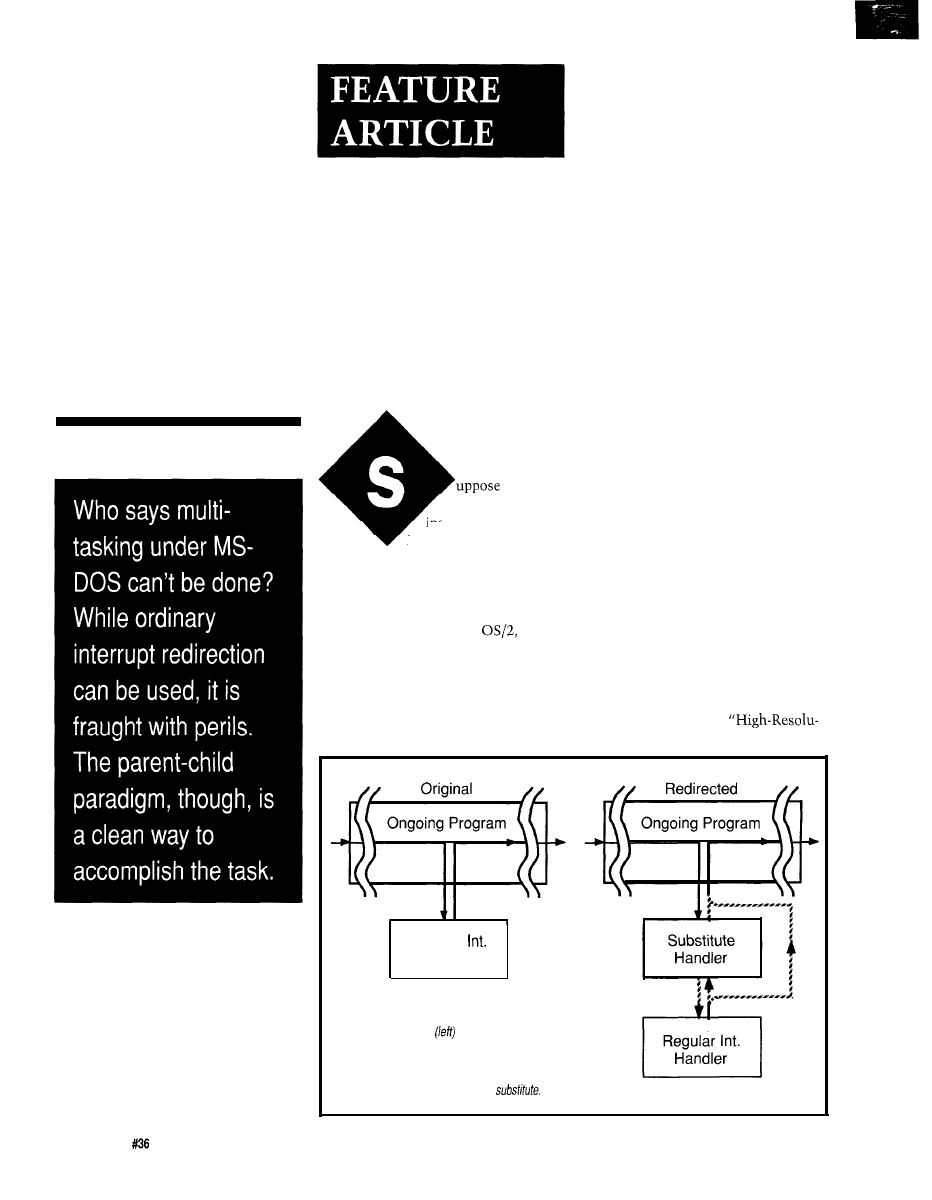
Regular
Handler
Figure l--The regular
program execution flow through
an interrupt handler
may be diverted to a substitute
handler (right). Optional paths are shown with the dotted
lines:
the substitute may return control direct/y or may use
the regular handler, and return from the regular handler
may then be direct or through the
2 6
Issue
July 1993
The Computer Applications Journal
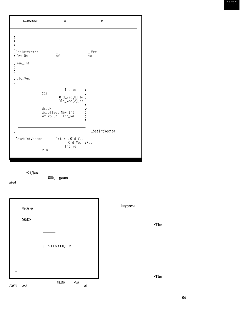
Listing
macros may be used substitute
interrupt handlers and restore the original
paths when done.
SET_INT.INC
Macros to set and restore interrupt vectors.
Set Interrupt Vector, saving old vector for later replacement.
Assumes new vector is in present code segment.
MACRO Int No, New Int, Old
is the number the interrupt be redirected.
is the location of the new interrupt handler.
It is assumed that the handler is in the code segment where
the macro is used.
is a four-byte space where the old interrupt vector
is saved.
mov
ax, 3500h +
Get old int. vector using
int
DOS function 35h
mov
word ptr
and save it
mov
word ptr
mov
dx,cs
Put interrupt segment
mov
code segment) in ds.
mov
put int offset in dx,
mov
Install new vector using
int
21h
DOS function 35h
endm
Reset Interrupt Vector
companion to
MACRO
lds
dx, dword ptr
back old int. vector
mov
ax, 2500h +
int
endm
tion Timing on a PC” (Circuit Cellar
from the main program long enough to
INK, Dec.
‘92, issue 24). A
update the system tick count. I’ll adapt
hardware interrupt, Int
is
Ackerman’s fast-timer for use as an
on each “clock tick,” which
example for my framework program.
normally happen at a rate of 18 times a
Keyboard input to a PC also
second, and the processor is diverted
occurs through interrupts. The
keyboard produces an
interrupt (Int 09h) to
CALL: INT 21 h, with registers:
Contents
store each
AX
4800 (Function number)
(and release). A second
ES:BX
Address of parameter block
kind of interrupt, a
Address of program name string
software interrupt, is
then used to unload
Parameter block:
Offset
Contents
the keyboard buffer;
o-1
Segment of environment block [0]
see Chris Ciarcia’s
2-5
Address of command tail
“Software at the Hard-
6-l 3
Addresses of file control blocks
ware Level” (Circuit
Command tail:
Cellar INK, June/July
Offset
Contents
1991, issue 21).
0
Length (n) of tail text in bytes
The neat thing
l - n
Tail text
about all of this is we
n+l
13h (CR) as terminator
can divert any DOS
indicates values to insert for default results.
interrupt for our own
purposes, as long as
Figure 2-A child
process is invoked by
function
and is named
we’re willing to accept
The
a/so includes a parameter block and a command
the consequences. DOS
even provides (through an interrupt, of
course) functions to help us do this.
But like all powerful tools, interrupt
diversion can really mess things up if
they’re not handled right. We need to
be sure to provide for the job the
interrupt normally does, as well as any
additional tasks we want done, and
then restore the state of the system
when we’re done.
The second requirement is crucial,
and can really make things go wrong if
it is not properly done. Imagine what
happens if you’ve told DOS that on
each keystroke or clock tick, it should
jump to a location (that you think is)
inside your program; if your program is
not present at that location, or your
program bombs and goes back to DOS
without removing the jump, every
thing may appear normal (since your
jumped-to code may still be in
memory), but as soon as you try to
load anything new, the diverted
interrupt will jump to some unpredict-
able place in a new program and try to
execute whatever “instructions” it
finds there! A runaway printer or a
frozen machine are common results,
but this kind of scenario can make
your worst “PC crash fears” possible.
HOW INTERRUPT DIVERSION
WORKS
Let’s see
what happens during an
interrupt. As I noted, interrupts can be
triggered by hardware or software. The
keyboard and the clock-tick interrupts,
Int 09h and Int 08h described above,
are examples of hardware interrupts. A
program gets keyboard-buffer contents
with a software interrupt, specifically
Int 16h. For either type of interrupt,
the same series of events
occurs:
current program location is
saved, in a subroutine fashion, to allow
a safe return from the interrupt.
*The four-byte address of the
appropriate interrupt handler
is
obtained from a jump table stored in
low memory. This address is called the
interrupt vector.
l
The interrupt handler (the code
at the address specified by the vector)
is executed.
handler issues an I RET,
causing a return via the address that
was stacked in the first step.
The Computer Applications Journal
Issue
July 1993
27
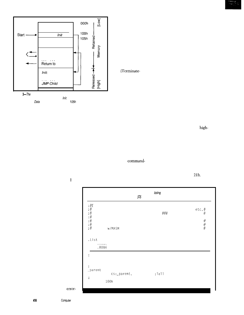
Child
DOS
Program Segment
Prefix
JMP
Data
. .
Child:
Do EXEC
Cleanup code
DOS
Setup code
Figure
arrows show program flow
through the structure of the parent
program framework. Memory from location
on is released before the child
program is called.
is placed at fixed location
where child program
routines can find it.
To substitute our own task, we
simply substitute our own interrupt
vector in the jump table. We could do
this directly, but that’s risky-suppose
we’re in the middle of changing an
interrupt vector when that interrupt
occurs? DOS makes life simpler and
safer by providing two functions to do
the job for us. How these functions are
used is shown in the first assembler
macro in Listing 1.
This macro also saves the old
interrupt vector. We will need this
when we reset things when we’re
done; the second macro in Listing is
the one responsible for that task.
Besides, we may still want to use the
old interrupt handler, but just add our
own code to it. After doing our thing,
we simply jump to the old handler,
where its I RET instruction returns it
neatly back to the main program. Or,
the return can be made through the
substitute handler rather than direct.
Program flow for the modified vector
interrupt handler is shown in Figure 1,
with dashed lines showing optional
routes.
THREE WAYS TO SET ‘EM UP
A straightforward approach to
interrupt diversion is to do it within
your main program. The program must
also provide foolproof restoration
when done. This means taking into
account irregular exits as well as
normal exits, including exits via break
keys (Ctrl-Break or Ctrl-C). Any
induced exits must
also be provided for,
particularly during
debugging, unless
the user of your
program loves
rebooting their
machine.
An alternative
is to set up the
diversions with a
TSR
and-Stay-Resident)
program triggered
by a hot key. The
advantage here is
that the TSR code,
once installed,
remains in memory
and can be invoked
through program calls and DOS
prompts. The disadvantage is the TSR
remains in memory, taking up space
and doing its thing, until something is
done to remove or disable it.
A third choice is the parent-child
program launching structure. A
program, called the parent, installs the
interrupt diversions and then calls up
the main program as a child process. A
child process can be passed
line arguments just like any other
program. The advantage to this
approach is when the child is done,
control is returned to the parent rather
than to DOS. The parent can then do
whatever cleanup is required (sound
familiar?). Breaks during a child
program need no special treatment
since control just goes back to the
parent. Many “bombs” in the child
processes will also return neatly to the
parent, which is very helpful during
debugging. Of course, the parent
program stays in memory while the
child runs. This is not as big a draw-
back as it might seem. Parent pro-
grams don’t have to be very big. The
prototype parent described below takes
less than one kilobyte of memory.
The parent-child scheme is a neat
one for the interface developer. All the
hardware stuff can be built into the
parent, written for efficiency in
assembler code, and tested with a
simple child program. After the bugs
are out of the parent, child programs to
handle the interface-related issues can
be written in any convenient
level language. If you work out
hardware systems for others who write
their own analysis programs, you can
let them write and fiddle with the
child programs.
HOW TO CALL YOUR CHILD
A child process is invoked by
(surprise!) an interrupt call, specifically
function 4Bh of interrupt
This is
called the E X EC function. The rules for
Listing
2-The parent program framework. Compare this
with Figure 2. Code to implement any
specific application is placed at [A] through
A
1
Template for Parent Program
for construction of programs that install interrupts,
for use in child programs. Stuff in
borders should be
replaced by appropriate code for the specific application.11
In this place write the program title, etc.
Template designed for the Microsoft MASM assembler;
tested
6.0
.NoList
Include Set_Int.Inc
model tiny
Start:
Go to one-time code that does the nitty-gritty, then
return here for clean-up and sign-off.
segment
assume
ds:_parent
MASM about
segment registers
org
(continued)
28
Issue
July 1993
The
Applications Journal
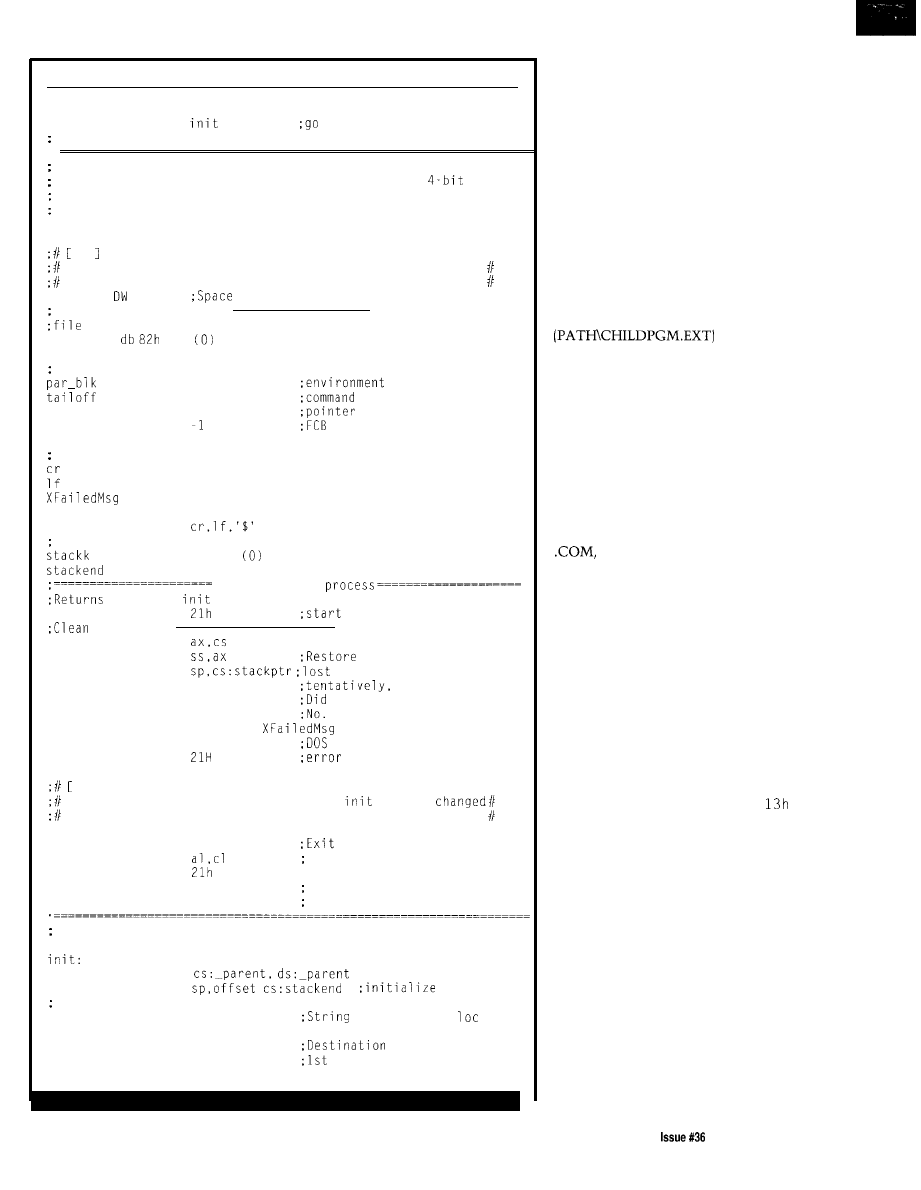
Listing P-continued
start:
jmp
do setup in over-write area
[Then return to child-execution segment]
Fix location to allow this info to be found by a child program,
via parent address in the child PSP.
Allows up to
jmp
address so child process can work with any future version of
this routine.
org
105h
B Parent Data
First goes data, etc., that child routine needs to find.
Here place interrupt handlers, vectors, etc.
stackptr 0
for stack ptr during DOS EXECUTE
Data for EXEC DOS call:
path buffer for EXEC DOS call. Also holds command tail
file-path
dup
EXECUTE parameter block-for EXECUTE DOS call
dw
0
segment-use 0
dw
0
tail
tailseg
dw
?
dd
pointers
dd
1
Error message
EQU
Odh
EQU
Oah
d b
cr,lf
db
'Failed to find and execute child program'
db
Local stack
dw
64 dup
dw
0
Run the child
here from
procedure
child:
int
the child process
things up:
mov
mov
stack seg and pointer
mov
in Child routine call.
mov
cl, 0
no error
jnc
pexit
it go OK?
If yes, exit
mov
cl, 2
Set exit DOS errorlevel 2
mov
dx,offset
mov
ah,9
string write,
int
message
pexit:
c 1
Restore vectors and other things that
routine
Note: Stack ptr need not be restored, DOS does it on exit
eexit:
mov
ah, 4Ch
to DOS
mov
errorlevel:
int
; 0
if Child executed
1 if no command line arg
2 if execution failed
Initialization code:
Used once, then released for use by child
assume
mov
stack ptr.
Get program from command string
mov
si, 80h
source is PSP
80h
mov
di, offset file-path
is file-path buffer
lodsb
byte of src is byte-count
(continued)
how the
EX EC
function works are
given in Figure 2. The mechanics for
how this function can be put to work
to suit our purposes will be better
understood after reviewing the listing
for the prototype. A place to start is to
write out the DOS command-line that
would be used to call up the child
program, such as:
C:>PATH\CHILDPGM.EXT with
some args
Now parse this command line to
divide it into a program-name part
and a
command tail (with some args). Each
of these parts is stored separately, and
has its own rules. Register pair DS:DX
contains, in DOS (segment:offset)
form, the location of the program
name. The name may include a DOS
path. The child program name must
end in .EXE or .COM followed by a
zero byte. Don’t omit the extension.
While a DOS command-line call will
find a program if you omit the .EXE or
the
EX EC
function will not.
The command tail is stored
differently. The register pair ES:BX
contains the location of a “parameter
block,” and this in turn contains the
location of the command tail. Ahead of
the tail is a single byte containing the
length of the tail string. Following the
tail is a carriage return character
(ASCII 13h). The carriage return is not
included in the length count. Thus our
example tail would be, in assembler
notation:
db 14, 'with some args',
The parameter block contains
three other pointers to areas we can
define for the child program: the
environment block and two file
control blocks. We will give these
default values, shown in the brackets.
In particular, putting a zero in the
environment pointer tells DOS to pass
the child the same environment the
parent got.
Our sample parent program will
read these child command parts from
its own command line. If the com-
mand line to invoke the child program
from a DOS command line were:
The Computer Applications Journal
J u l y 1 9 9 3 2 9
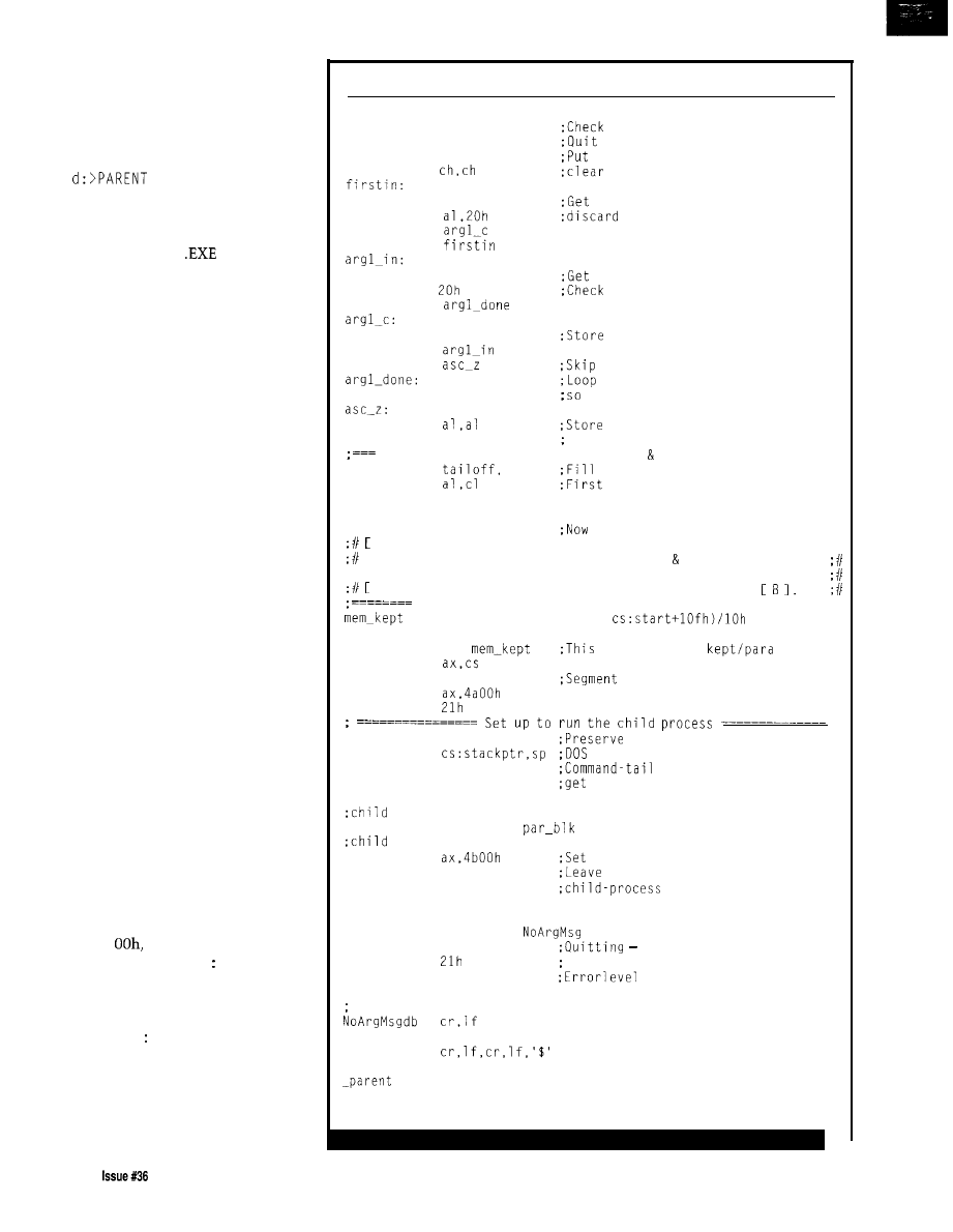
d:>path\CHILDPGM with
some args
then the command line to start the
same program as a child should be:
path\CHILDPGM.EXE
with some args
Note that the command-line entry is
made including the
extension,
and is followed by the command tail.
A PARENT PROGRAM
FRAMEWORK
Now I’m ready to describe how to
make a prototype parent program. The
minimum tasks such a program must
perform are laid out below:
(1)
Fill child process program name
and command tail from parent
command line.
(2) Divert interrupts and do any
other application-specific setup.
(3) Assign memory for use by child
process.
(4) Call child via EXEC Function.
(5) Put things back as they were
(i.e., undo step 2).
I’ve described all of these, except
for number 3-assign memory for the
child. When the parent (or any pro-
gram) is called, DOS generously
assigns it all the memory available. A
parent must release what it doesn’t
need. In order to give the child every
byte we can, I’ll release not only the
memory not occupied by the parent,
but also the space the parent uses only
once, before the child is called. This
takes a little extra planning, but it
means I don’t need to squeeze and
skimp on setup code. The memory
layout of the parent is shown in Figure
3. At the DOS entry location, relative
address
1
there’s an immediate
jump to location I n i t to perform the
set up, after which we jump to
C h i 1 d : , which is the location of the
call to the child program. Memory
from I n i t can be released after the
code has been processed.
The data area has been placed
immediately after the J M P I n i t
statement. This fixes its location so
the child process can find it. I skipped
Listing 2-continued
cmp al. 0
for a zero count
jz
abort
if no argument
mov cl, al
count in cl
xor
high byte
lodsb
char. from command line
cmp
any leading space
jne
loop
lodsb
char. from command line
cal,
against space
je
stosb
it in file-path name
loop
jmp
if loop ended due to count
ended due to space
dec cl
count it but don't copy it
xor
a zero to terminate
stosb
the ASCIIZ string
Define the new command-tail buffer put the rest there ===
mov
di
in tail-pointer from di
mov
the count
stosb
inc cl
;Add one so we'll copy the cr
rep
movsb
copy string with term. cr
D
1
Write code to redirect interrupt vectors do any other
system setup. Changes made here should be unmade by code at
c
1.
"Old" interrupt vectors should be stored at
Release all possible memory for use by child ========
EQU (offset cs:init-offset
mov
bx,
is size to be
mov
mov
es,ax
for release reference
mov
;DOS release-memory function
int
stack pointer!
mov
EXEC Interrupt loses it!
mov
tailseg,cs
segment for ptr.
pointers for DOS function:
mov
dx,offset file-path
process name/path
mov
bx,offset
process par. block
mov
for DOS "EXECUTE" function
jmp
child
once-only code, go to
call location.
:====Error routine for missing command-line Child program name====
abort:
mov
dx, offset
mov
ah,9
no valid argument
int
on DOS command line
mov
cl.1
1 on pgm exit
jmp
eexit
Error message text:
db
'No valid argument on DOS command line.'
db
ends
end
start
30
July1993
The Computer Applications Journal
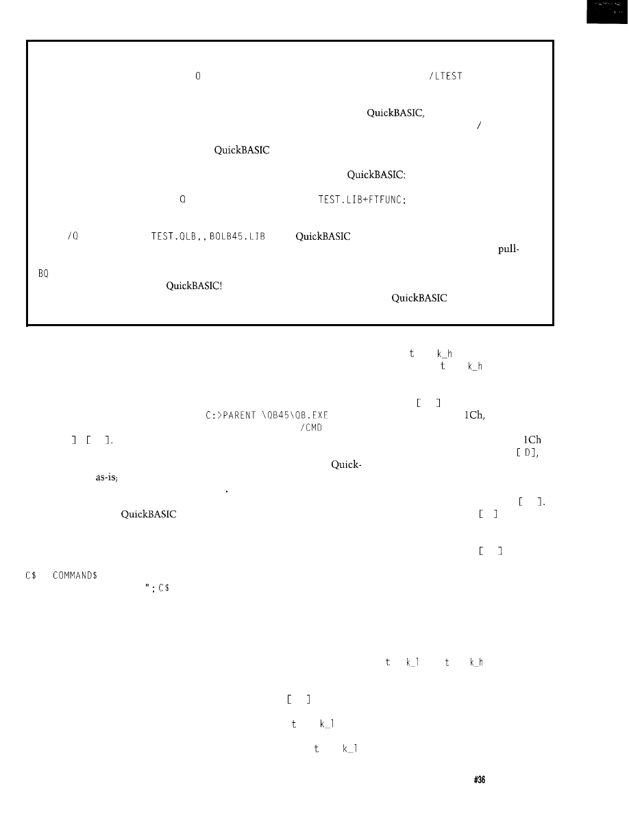
ADDING SUBPROGRAM OBJECT MODULES TO PROGRAMS
For FORTRAN, the module FT FU N C
.
B J is combined
with the parent by simply listing it on the compiler
command line:
FASTIMER QB.EXE FASTEST
The line items in this example are, from left to right, the
parent program,
the test program, and the
FL MAINPGM.FOR FTFUNC.OBJ
Quick Library name preceded by the switch L. If you
plan to make a stand-alone program, you should also
To include an assembly coded routine in
is
make a regular library. A one-file library is very quickly
a little more involved, and described pretty briefly in the
made with Microsoft’s library manager L I B, which also
manuals. I’ll run through the steps for our test program.
comes with
A routine to be used within QB must be part of a “Quick
Library,” conventional extension
.
LB. A Quick Library
LIB
TEST.QLBcanbemadeby:
All this works just fine when it works. However,
LINK FTFUNC.OBJ,
has five paths to set, and they all matter.
There’s a “Set Paths” submenu on the Options
This is shown for version 4.5, thus the name
down menu within QB. The time to get all the paths
LB45. L I B. Be sure to use the version of Microsoft
right is well spent. This will create or update a file
L I N K that comes with your
The Quick
QB . I N I in your default directory; check that this file did
library is then included on the command line, which now
get written. Note that
looks for each file in
looks like:
the default directory before using one of these paths.
forward five bytes, although the J M P
only needs three. If I ever design a
parent that uses S-byte jumps,
I
won’t
have to rewrite any of the child
program subroutines.
Listing 2 shows my parent
framework. Code for specific applica-
tions gets inserted at four locations,
marked [A to D I’ve described
some of the finicky details in com-
ments. The framework can be com-
piled and tested
it doesn’t do
much, but can be tested and used as a
proof of concept.
Below is a simple
program called COPY CAT. BAS, which
just prints out its own command-line
arguments.
=
PRINT "Copycat says:
END
When C 0 PY CAT is compiled and run,
its output is:
C:>COPYCAT Meow
Copycat says: MEOW
The following shows the same com-
piled program being run as a child,
verifying that PARENT passes along the
rest of the command line when it calls
COPYCAT.
C:>PARENT COPYCAT Meow
Copycat Says: MEOW
An intriguing wrinkle to parent-child
method is shown below:
COPYCAT
meow
Copycat Says: MEOW
where the parent can use the
BASIC “programming environment”
(Q B E X E) as its child! After QB loads
itself and the COPY CAT
text,
pressing
the Run key produces the output
shown. I haven’t tried this experiment
with other programming environ-
ments, but I suspect most of them will
work just as well. As a result, a child
program being prepared to run in
compiled form can be written, tested,
and debugged within a modern,
convenient programming frame.
THE FAST TIMER PARENT
Listing 3 contains the patches
needed to build a parent program for
the fast-timer technique that was first
described by Ackerman. At the start of
the patch in section B are two words
(four bytes) reserved at location 105h
for a counter. The first, i c
o, will
be incremented approximately 18
times per second. Each time i c
o
overflows (almost exactly once an
hour), i c
i is incremented. An
overflow from i c
i will occur
some time in the eighth year.
The counter routine in the Patch
section B is our substitute handler
for DOS interrupt
which is a
secondary DOS timer interrupt. The
instructions that divert calls on
are shown in the patch section
which is executed when the parent
starts. We also need to change the
mode of the PC’s timer-that’s the job
of the remaining code in section D
Finally, patch section C is executed
on return from the child, and it
contains the steps needed to undo
what’s done in section D and turn
over a “clean” PC to the next program.
COMMUNICATING WITH
YOUR CHILD
The final part of our fast-timer
package is a pair of subroutines that
can be called in a child program to read
the DOS clock and add to the data in
i
c
o and i c i if necessary.
How does such a routine find these
values? When writing or compiling a
program, we don’t know just where in
memory it will be at run time. If we
want to pass data between parent and
child, the child needs a way to find its
parent. The DOS program loader
The Computer Applications Journal
Issue
July 1993
31
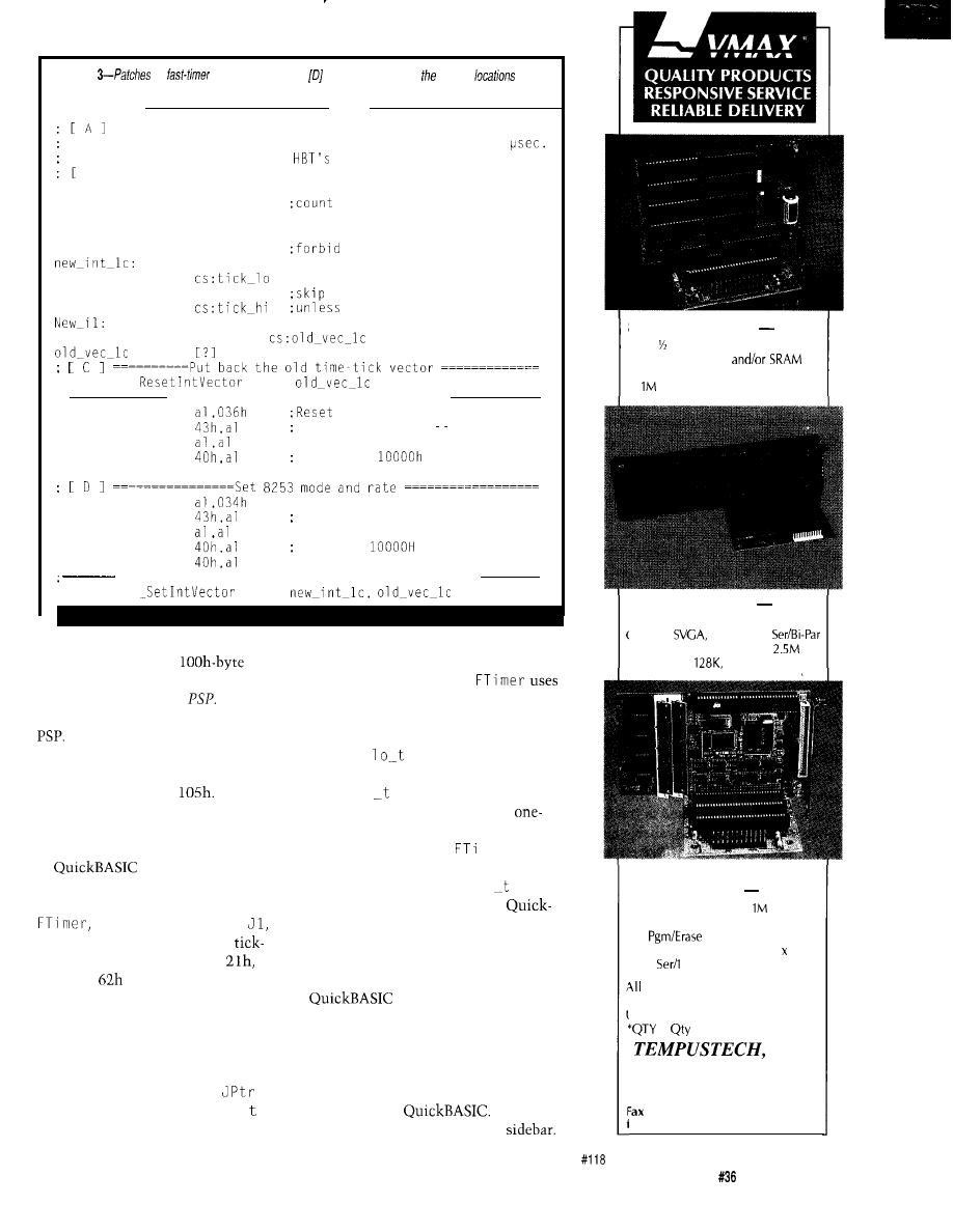
Listing
for
example. [A] through should be inserted at marked
in
Listing 2.
Fast-Timer Parent Program
Sets up fast clock for child process, allowing timing with
res. using PC clock. Built on
standard Parent Framework.
Bl
Tick Data
org
105h
tick-lo dw
0
buffer
tick-hi
dw
0
; New tick-count handler:
assume ds:nothing
use of ds (contents unknown)
inc
jnz
New-11
next instruction
inc
count overflowed
jmp
dword ptr
DD
lch,
Restore 8253 chip mode and tick-rate
mov
8253 chip
out
control register mode 3
xor
out
count to
out
40h
mov
out
control register: mode 2
xor
out
count to
out
Install new old time-tick vector, save old one
lch,
conveniently places the parent
two instructions after J 0 reset it to
location in the initial
block
point at J 1, shortening all subsequent
of the child program, called its Pro-
FTimercalls.Therestof
gram
Segment
Prefix
or
There’s a
Ackerman’s technique to fetch the
DOS function to find a program’s own
DOS clock count as the least-signifi-
Finally, once we’ve found the
cant two bytes of a four-byte integer,
parent, we know the location of its
and gets
i
c
k from the parent as
data area, since we carefully placed
the most-significant bytes. It also
this at parent address
fetches hi i c k and squirrels it away.
My routines for doing this are
shown in Listing 4. They can be called
from Microsoft assembler, FORTRAN,
or
(other languages
should work as well, but these are the
ones I’ve tested). Near the start of
between labels JO and
is
a
section that finds the parent
count locations. A call to Int
Function
returns the child’s PSP
location, which in turn serves as a bast
to fetch the parent location. The
parent’s base address is then stored for
future use, so this code section only
needs to be executed once. The
instruction
JMP WORD PTR
provides a switch: the pointer J P r
originally points at J 0, but the first
For many applications, the
hour time range of
FT i me r
will be
enough. If not, a call to
me r may
be followed by one to
FT i me r H
i ,
which fetches the last saved hi
i c
k
value. In both FORTRAN and
BASIC, these routines are used as
functions. They have no arguments,
and so avoid one source of pitfalls in
interlanguage programming. A simple
demonstration program
is shown in Listing 5. I’ve included a
function that translates the time into
seconds. Combining a subprogram
object module with a main program is
straightforward in FORTRAN, but a
little tricky in
Instruc-
tions for doing both are in the
SOLID STATE DISK
$135”
Card
2 Disk Emulator
EPROM,FLASH
Program/Erase FLASH On-Board
Total, Either Drive Bootable
The Computer Applications Journal
Issue
July 1993
33
25MHZ 386DX CPU
$695”
Compact AT/Bus or Stand Alone
In-Board
IDE, FDC, 2
FLASH&RAM Drives to
Cache to
DRAM to 48M
TURBO XT
w/FLASH DISK
$266”
To 2 FLASH Drives,
Total
DRAM to 2 M
FLASH On-Board
CMOS Surface Mount, 4.2” 6.7”
2
Par, Watchdog Timer
Tempustech VMAX products are
PC Bus Compatible. Made in the
J.S.A., 30 Day Money Back Guarantee
1,
breaks start at 5 pieces.
INC.
TEL: (800) 634-0701
FAX: (813) 643-4981
for
ast response!
295 Airport Road
Naples, FL 33942
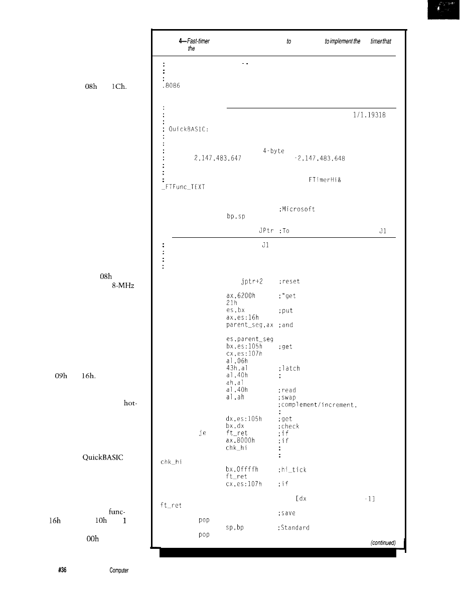
PROSPECTS
Now that I’ve shown you how the
parent-child structure works, let’s take
a look at some things that can be done
with it. First of all, I’ve barely
scratched what can be done with the
timer interrupts, Int
and
Parent routines could be modified to
acquire data from an instrument on
every DOS clock tick. The frequency
of DOS “ticks” could be changed to
provide more frequent sampling. The
method for doing this was also
described by Ackerman, and earlier by
C. Claff in BYTE (1986 IBM Extra
Issue, p. 254). The handler can place
the data in buffers for later use by an
ongoing program. That program can,
if you like, set flags to direct and
control the data-gathering process on
the fly.
I would like to share one of my
experiences as an example of how
speeding up the “tick” can be put to
good use. I once built a program that
logged signals from a bank of 144
phototransistors and also watched an
ADC output, by using Int
sped up
to 146 ticks per second on an
PC/AT-level machine. The main
program, written in FORTRAN, could
retrieve data as needed and wring out
the results in real time. This approach
to the data acquisition process slowed
the main program down by less than
10%.
The interrupts most commonly
diverted are those for the keyboard,
namely Int
and
All “hot-key”
add-on programs grab these. You can
roll your own here too, and in some
cases you may need to. Available
key programs can clash with a given
application since almost every applica-
tion program handles keyboard input
differently. Diverting these interrupts
within a parent program can be used to
add a hot key to the
programming environment. Doing so
let me lay down templates for WHILE
and FOR loops, IF-ELSE structures,
and the like. By the way, if you do
adapt Ciarcia’s code, be sure to add
traps for enhanced-keyboard
tions-Int
functions
and lh.
Apparently these can be handled just
the same as functions
and Olh,
respectively.
Listing
functions. These should be linked child programs
fast
is set up by parent.
Fast Timer Function These functions, used with program
FASTIME, return the time to a BASIC or FORTRAN program,in
internal timer pulses, frequency 1.1931817 MHz.
_FTFunc_TEXT
SEGMENT BYTE PUBLIC 'CODE'
_FTFunc_TEXT
ENDS
Function FTimer
No arguments. Returns the current time in units of
microseconds, in DX (high 16 bits) and AX (low 16 bits).
DECLARE FUNCTION FTimer&.
The four-byte result is an unsigned integer, and overflows at
1 hr. If read as signed
integer, the count goes from
0 to
and then from
to -1. then
overflows and repeats.
The overflow causes a second counter
to be incremented, providing an additional two bytes of total
count. The overflow count is read by
if needed.
SEGMENT
PUBLIC FTimer
FTimer
PROC
FAR
push bp
Standard Entry
mov
push es
JMP
WORD PTR
JO the first time, then
The code between JO and is executed on the first entry,
bypassed on later calls.
It finds and saves the segment of
the parent program, so that the tick recorded there can be
used as the most significant part of the value.
JO:
jl:
mov
mov
mov
int
mov
mov
mov
ax,
jptr. ax
mov
mov
mov
mov
out
in
mov
in
xchg
not
ax
inc
ax
mov
cmp
cmp
jb
mov
dx.bx
cmp
jne
mov
add
cx.dx
mov
mov
hi_count,cx
es
bp
to skip this next time
PSP" DOS call
psp seg in es
;get parent PSP seg
save it
initial tick reading
and tick overflow
the count value
read LS byte
MS byte
to
change count-down to count-up
present tick reading
whether lo-tick changed
it didn't change, we're ok;
it did, decide which to use.
count small: use second
count large: use first
ok unless
lo-tick overflowed.
so get present value
and perhaps subtract 1
is either 0 or
hi-tick
exit.
34
Issue
July 1993
The
Applications Journal
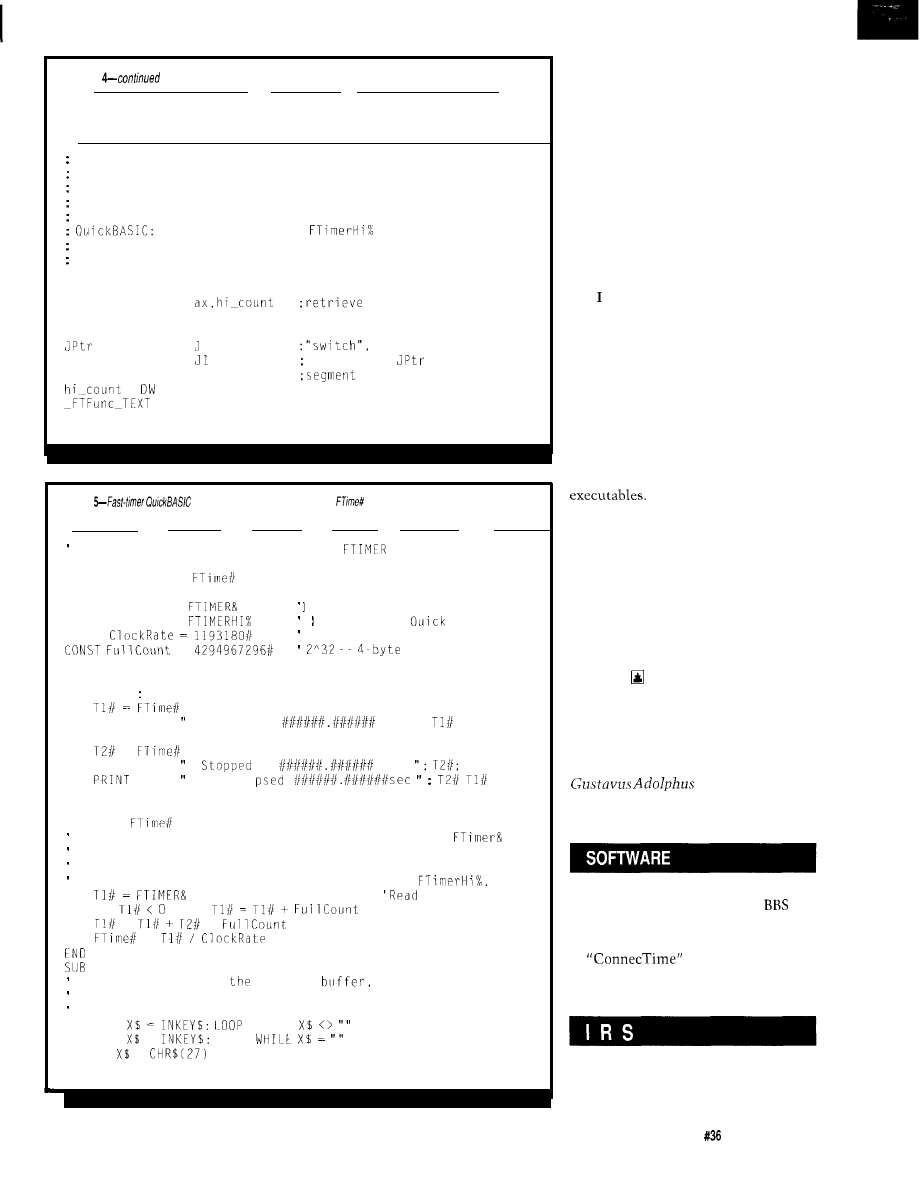
Listing
ret
FTimer
ENDP
_
_
Function FTimerHi
No arguments.
Returns the overflow (high count) is AX.
This
function is meaningful only after a call to FTimer -- the
value returned is the high tick count at the time of
FTimer call.
DECLARE FUNCTION
The count returned is an unsigned integer.
Each high count
is worth one hour.
PUBLIC FTimerHi
FTimerHi
PROC
FAR
mov
the high count.
ret
FTimerHi
ENDP
DW
0
starts at JO
DW
inserted in
on first call
parent_seg DW
0
of start of parent pgm.
0
ENDS
END
Listing
demo program. The function
returns the time in seconds as a
double-precision floating point number.
Simple Demo Program for the routines
and FTIMCRHI
DECLARE FUNCTION
0
DECLARE SUB WaitForKey 0
DECLARE FUNCTION
These functions must be in
DECLARE FUNCTION
a loaded
Librarv
CONST
=
CLS
DO
PRINT PRINT
PRINT USING
IBM PC Timer tick rate, Hz
full count
"Hit a key to start timer": WaitForKey
Started at
sec.";
PRINT "Hit a key to stop timer": WaitForKey
=
PRINT USING
at
sec.
USING
E 1 a
:
LOOP
END
FUNCTION
Function to convert time from Fast Timer subroutine
into
a double-precision real value in seconds. Negative values are
converted to the appropriate unsigned-integer positive values,
and overflow counts obtained from the function
the timer
IF
THEN
'Convert val. to +
=
*
'Add any overflow
=
'Convert to seconds
FUNCTION
WaitForKey
This routine flushes
keyboard
thrn waits for a
keystroke. An ESC stops the program. Any other normal keystroke
continues.
DO:
WHILE
'Clean out buffer
DO: =
LOOP
'Wait for first key
IF =
THEN SYSTEM
'Use ESC key to stop
END SUB
Parent programs can perform
many useful purposes. One that I built
for a college instructional network
runs a sequence of “children” with
each child able to control what other
child gets to run next, provides a buffer
for inter-program data exchanges, and
maintains a legally required security
record in a campus network environ-
ment.
ARE PARENT PROGRAMS PROUD
OF THEIR CHILDREN?
hope you too will find the
parent-child program structure a
powerful and versatile tool. Perhaps a
more developed parent-child environ-
ment can provide other useful func-
tions in the realm of virus detection,
additional run-time controls such as
passwords to individual programs, and
so forth. Let me know if you discover
any interesting uses, possibilities, or
quirks to this method of launching
For those of you with a yen to go
beyond the scope of what I presented
here, the best source I know for
practical information on DOS is “The
DOS Programmer’s Reference,” second
edition, by Terry Dettmann and Jim
Kyle, published by Que Corporation in
1989. This book contains lots of data
on DOS interrupts and the E X EC
function.
Brad Thompson holds a Ph.D. from
Michigan State University. He works
on computer instrument interfaces
and instructional program systems at
College, Saint
Peter, Minn., where he is Scholar in
Residence in chemistry and physics.
Software for this article is avail-
able from the Circuit Cellar
and on Software On Disk for this
issue. Please see the end of
in this issue for
downloading and ordering infor-
mation.
404 Very Useful
405 Moderately Useful
406 Not Useful
The Computer Applications Journal
issue
July 1993
35
High-speed
Modem
Basics: The
Working
Hardware
A CLOSE LOOK AT THE DAA
The DAA is the main interface
between the modem and the telephone
company
primary
purpose is to provide necessary isola-
tion (up to 1500 volts, so your equip-
ment won’t damage the telco’s equip-
ment and a lightning hit on the telco
line won’t blow up your end) without
distorting or otherwise affecting the
analog data stream. The DAA also
performs all telco-related functions
such as taking the line off hook,
detecting ring signals, and doing
to
conversion.
Many times
are imple-
mented using discrete components, but
Michael Swartzendruber
0
ast month I
explained some of
the common standards
that relate to modems and
also showed what gains in throughput
and performance state-of-the-art
modems are trying to achieve. The
purpose of that discussion was to take
some of the mystery away from this
very deep pile of jargon. This month I
am going to step away from the
abstract and get down to some hard-
ware by building the Gemini project.
will also take a close look at the way
the Gemini works.
There are two primary vendor
technologies that come together to
create the core of the Gemini modem:
Exar and Cermetek. Exar is an estab-
lished provider of modem technologies
and offers a wide variety of modem
chip sets. Cermetek specializes in
hybrid assemblies. Among their key
offerings are fully integrated
socket modems” and Data Access
Arrangements (DAA).
I chose the Cermetek hybrid DAA for
a few key reasons:
*Simplified circuitry design
(replacing several
with one
component) made the prototype easier
to build and the circuit board easier to
lay out.
l To simplify any future dealings
with regulatory agencies, I chose to
include the Cermetek DAA in my
design since it meets or exceeds all
regulations for a DAA (see last
month’s issue for a list of these
requirements). This saves me the step
of having to prove the compliance of
the DAA in the Gemini.
simplification of the analog
circuit (especially in the realm of
isolation between the Gemini and the
telco) took away my worries of
connecting my prototype to the telco
(the last thing I needed was to upset
those guys).
make it easier for others
building the Gemini who might have
concerns very similar to my own.
THE CERMETEK DAA
Working with the Cermetek 18 17
is a snap. The device runs on a simple
supply and has two control lines
and two signal lines. The control lines
consist of Off Hook (high true) and
Ring Indicator (low true pulses). The
Off Hook pin is an input to the DAA
that the modem controls. Taking this
line high causes the DAA to indicate
to the telco that the phone is “off the
hook.” The Ring Indicator is an output
that will pulse low for the duration of
the ring signal from the telco (typically
two seconds) and will return to the
high state between rings (typically four
seconds). The resistor
and the
capacitor (C47) that are connected to
the Ring Indicator pin of the DAA are
used to produce a ring envelope from
the Ring Indicator signal.
The DAA also has XMIT and RCV
pins for use with analog signals from
and to the modem. The
pin is an
input to the DAA and accepts the
analog data stream from the modem.
This pin must he
to the
modem’s transmitter. The RCV pin is
the converse of the XMIT and is used
to forward analog data from the telco
to the modem. This pin should also be
Issue
July 1993
The Computer Applications Journal
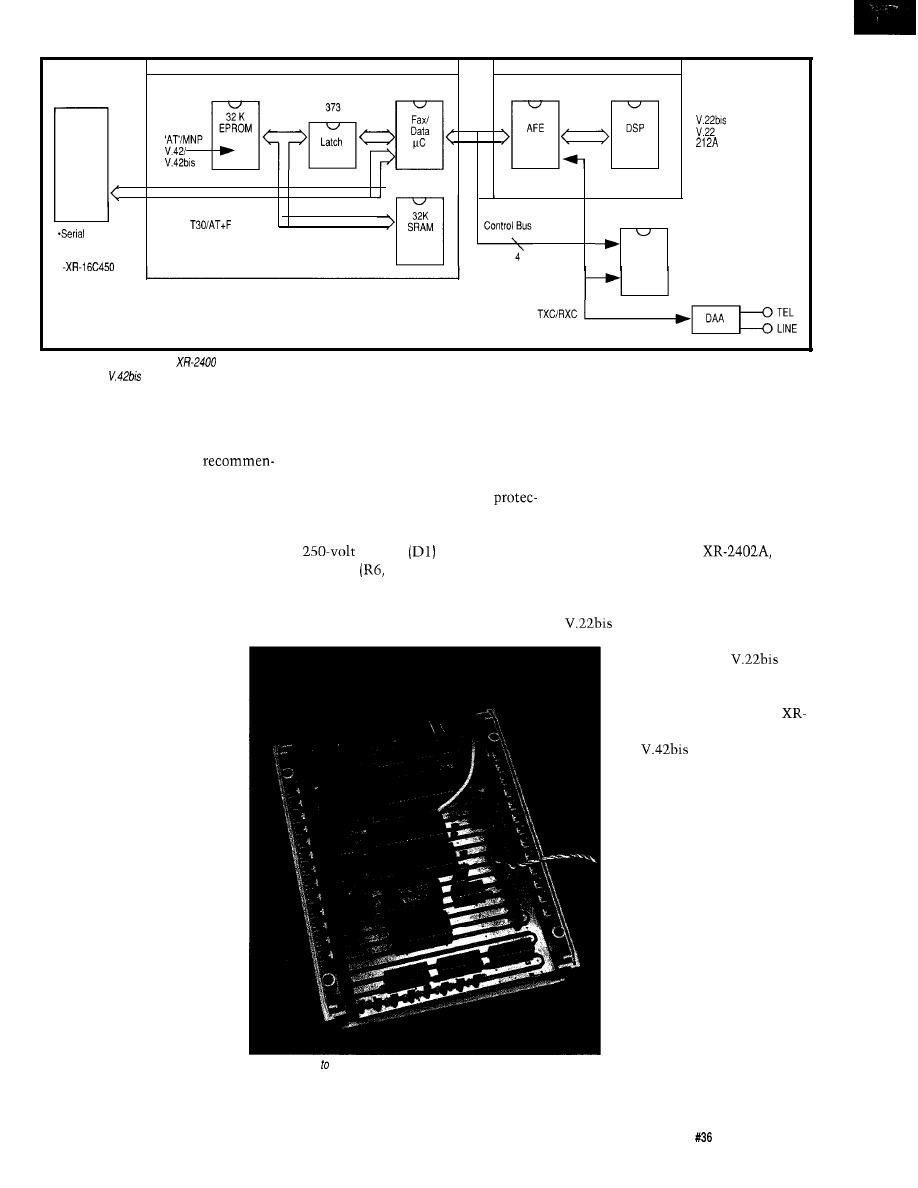
DTE
Interface
RS232
-148811469
*Parallel Bus
UART
27256
XR-2443
XR-2402A
XR-2401
55256
Commands
XR-2321
F S K
Modem
103
V.23
v.21
Figure l--The front end of the
chip set is responsible for taking in the analog data stream and extracting digital data, where it gets passed along via the control bus to
the
XR-2443 for
compression.
AC coupled to the modem’s receiver
into the telco from the modem and
Gemini schematic on the page that
circuit.
surge protection. These components
illustrates the telco connection.
The application note for the DAA
are not required, but can be a nice
makes some very specific
enhancement-especially if you are
THE EXAR CORE
dations regarding the layout of circuit
going to go through EMI/RFI testing.
The core of the Gemini modem
traces connecting to, or passing close
I added the optional surge
consists of the XR-2400 chip set and a
to,
the DAA. Most of these recommen-
dations are made to enhance the odds
that your design will pass FCC (or
other agency) testing. I was not able to
comply with them on the prototype
(although I did my best), but I did
comply with them for the circuit board
I designed for the Gemini.
Among the recommenda-
tions are some specific to the
distance between traces
(especially those on the telco
side of the device). The tip and
ring traces must be separated
from each other by 0.1 inch
and from all other traces by
0.2 inches. In addition, the tip
and ring traces must have a
nominal width of 20 mils.
Furthermore, these traces
should be kept as short as
possible and should be laid
out to prevent signal coupling
to any nearby traces. Other
recommendations for power
supply bypassing are included,
but many of these are not
exceptionally different from
normally applied design rules
for any integrated device. The
application note also includes
information concerning ways
to minimize EMI/RFI injected
tion circuit that they recommend. The
small amount of supporting glue logic.
surge protection circuit consists of a
The chip set contains three primary
varistor
and series
devices: the XR-2400,
and
resistors
R26) between the telco
XR-2443.
network and the surge protector. This
The XR-2400 is a DSP-based
small (and completely optional) circuit
modem signal processor and provides
enhancement can be seen on the
modulation and demodulation
functions. The XR-2402A is a
high-performance
AFE
(Analog Front End) which
provides a whole slew of
functionality. Finally, the
2443 is a microcontroller with
the
compression
algorithm (among other
things) built right in. A block
diagram of the chip set as it
relates to the Gemini is in
Figure
1.
Photo
l--Thanks
a dedicated chip set, the bulk of the modem functions are
done in just a few big chips. Gone are the days of lots of touchy analog
electronics inside modems.
The front end of the
modem has the responsibility
of accepting the analog data
stream and extracting the
digital data contained on the
carrier wave. It must also
accept digital data from the
“rest of the modem” and
modulate that data onto the
carrier for telco network
transmission. In short, the
front end of the modem
provides the modulation and
the demodulation services.
The Computer Applications Journal
Issue
July 1993
39
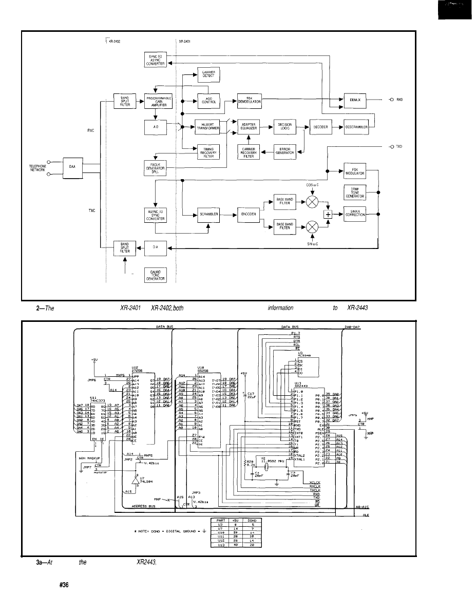
Figure
front
end is composed of the
and
of which exchange and process data
before sending if the
and the DAA.
Figure
the
core of Gemini modem is the
a custom-programmed 8031 processor.
4 0
Issue
July 1993
The Computer Applications Journal

Although the XR-2402A is the AFE
used in the Gemini, it is also involved
in almost everything that goes on in
the modem.
The 2402 contains the A/D and
D/A converters. As you might expect,
the D/A converter is used to create
analog signals for injection into the
telco, while the A/D accepts analog
signals from the telco for further
processing by other devices in the
modem. Before the signal from the
telco is presented to the ADC on the
AFE, it passes through a programmable
gain amplifier (PGA). The gain of this
amplifier is set by an AGC and control
circuitry (used to control the PGA)
that resides in the XR-2401.
The 2402 and the 2401 are a
tightly knit pair. The output from the
ADC on the 2402 is fed into several
functional blocks on the 2401. Among
these blocks is a timing recovery filter,
the output of which feeds back to the
2402 and drives a phase-locked loop
whose output is then fed back into the
2401 to control the input switches to
the adaptive equalization circuit in the
240 1. To further complement the data
reception functions, the output of the
I don’t want to find out how can save a lot of money using
ROM-DOS
5 instead of MS-DOS@ in our 80x86 product line.
I don’t care if ROM-DOS 5 iscompatible with MS-DOS 5 but
costs much less. I
like
spending much more than I have to.
It makes me feel like a philanthropist and besides Microsoft@
probably needs the money more than I do anyway.
I want to know the facts about ROM-DOS 5.
Please send information and a free bootable demo disk to
try with my software.
the
or
fax this coupon to (206) 435-0253.
Name
Company
State
Phone
zip
307 N.
OLYMPIC. SUITE 201
l
ARLINGTON. WA 98223 USA
l
l
FAX:
descrambler (this generates the CRC)
in the 2401 is fed back to a synchro-
nous-to-asynchronous converter in the
2402. The output of this block is fed
back into the demultiplexer block of
the 240 1. The data transmission (from
the modem to the telco) goes through
both devices in a similar manner.
When data arrives from the modem to
be transmitted to the telco, it is fed to
the
converter in the
2402. The output from this converter
is fed into the scrambler (generates the
CRC) along with the data that is
bound for the telco. A block diagram
showing how these two devices are
connected is shown in Figure 2.
In addition to serving as the DAA
signal gateway, the AFE controls the
amplitude of the signal that is used to
drive the speaker during call progress
monitoring. The 2402 also has status
bits that can be read by the host
microcontroller to indicate carrier
detect and normal energy reception
(high and low band). Low-band
detection is used to indicate dial, busy,
and ring-back tones. The speaker
control functions (including mode and
volume) reside in a register in the
2402.
The 2402 also serves as the
control point between the front end
and the microcontroller. The chip is
accessed from the microcontroller like
a memory address; it has the intelli-
gence to recognize commands that
belong to the 2401 and will forward
them to that device. The 2402 will
also forward status and data informa-
tion in both directions between the
2401 and the microcontroller. When-
ever the 2402 receives data bound for
the 2401, it generates an interrupt to
the 2401. The ISR in the 2401 locates
the information (data or command)
and acts on it appropriately.
The 2401 contains a register that
determines its mode of operation,
which include idle mode, DTMF
mode, or, if engaged in a data transfer,
which modulation method to use (FSK
or DPSK). The 2401 contains a DTMF
generator that is controlled by the host
microcontroller. The output of the
generator is completely dependent on
the data written to the 2401 while it is
in DTMF mode.
The Computer Applications Journal
Issue
July 1993
4 1
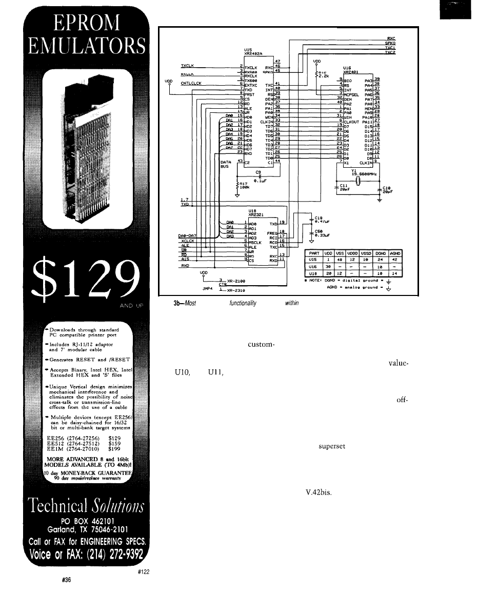
Figure
of the modern
is
contained
three custom chips that are closely linked and work
hand in hand
THE BRAINS
The XR-2443 processor is really
just an 8051 that contains a
masked ROM designed by Exar. If you
look closely at the circuit consisting of
U13,
U12,
and U5, you can
see “just another 8031” single-board
computer. The 2443 ROM provides
command control over the 240 1 and
the 2402 by translating AT and MNP
commands into commands specific to
the operation of the chips. The actual
commands (AT and MNP) reside in the
EEPROM installed in the modem. This
makes evolution of the AT and MNP
command sets possible without
requiring changes to the 2443 ROM.
The firmware supplied by Exar
provides full AT and MNP command
set compatibility.
For those who want to go the extra
mile, Exar also provides a fully
decoded memory map of the EPROM
and the RAM, the address ranges used
by the Exar-supplied firmware, all the
interrupts used in their firmware, and
a full list of the entry points used in
their firmware along their hexadecimal
addresses. They provide this detailed
level of documentation to simplify
the effort required in creating
added software for their core technol-
ogy.
In summary, Exar provides
everything you need to make an
the-shelf modem through a straight
application of their technology. They
also give you all the information
necessary to extend their firmware to
create a
of what they bring to
the table. The biggest advantage to
using the 2443, though, is the fact that
it contains pretested code that imple-
ments MNP levels 2-5 as well as V.42
and
DESIGNING WITH THE EXAR
CHIP SET
The data and applications notes
for the Exar chip set make some very
specific recommendations for layout of
components and traces. One of the
4 2
Issue
July 1993
The Computer Applications Journal
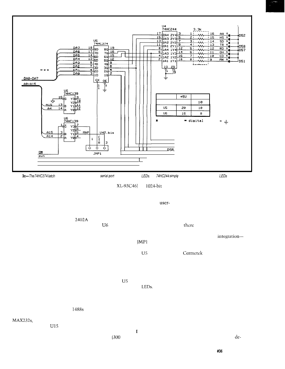
Udd
9
D 5 4
D 5 6
D 5 5
D 5 3
DATA
BUS
ADDRESS
BUS
PART
u 4
DGND
2 0
N O T E
DGND
ground
O H
HS
CD
L
CTS
I I I
DTR
I
TXD
Figure
holds the status bits for both the
and the front-panel
The
provides drive current for the
points they emphasize is that digital
ground and analog ground should be
kept separate up to the point where
they enter the power supply. Obvi-
ously, the better your ground plane,
the better off this circuit will be. In
addition, they stipulate that the
should be as close to the DAA as
possible to keep these traces short.
The traces carrying the analog KX and
TX signals should be kept as far away
from digital signals as possible. They
also recommend lots of bypass caps,
which should be mounted as close to
the power pins as is possible.
WHAT ABOUT THE REST?
In order to make the core chips
happy, the Gemini also includes a
handful of support logic. The final
schematic is shown in Figure 3.
The RS-232 interface level shifting
is accomplished with ordinary
and 1489s. I could have used
but since I needed negative
supply voltages for
and U19
anyway, I was able to save some
money and board space.
and made active, and up to three
U3 (an
is a
phone numbers.
serial EEPROM that is used to store
interesting things like user-defined
power-up settings, two additional
definable settings that can be recalled
THE LONG AND THE SHORT OF IT
half duplex) support to the modem.
While neither standard is used much
in the U.S., European users might find
them handy.
But, after exploring some of the
So there you have it. As you can
see,
is not much magic going on
inner workings of modems by building
inside a modem these days. With the
increasing amount of
especially analog integration such as
the Gemini, I wonder if maybe the
that found in the 2401, the 2402, and
the
DAA-products of
term “modem” has outlived its
increasing complexity can be created
from readily available components.
usefulness. Sure, these devices still
Implementing precooked microcon-
perform basic modulation and
trollers (those with masked ROMs
such as the 2443) is another way to get
more products to market in short order
because they allow you to leverage off
the work already done and packaged in
the component.
Just for good measure, I also
included the XR-2321 in the Gemini.
acts as little more than an
address decoder. It has two outputs
This single-chip modem is not re-
that are enabled on converse states of
Al4 and A15. Jumper
selects
which of these strobe signals will be
quired at all for the Gemini to operate
used to clock U5. When
is clocked,
in most of its modes. threw it in to
it forwards the data on the data bus to
its output side. Therefore, U5 is an
add V.21
bps) and V.23 (1200 bps,
output port in relation to the XR-2443
microcontroller. The data on the
output side of
is used as an input to
U4, which drives status
The
outputs of U5 also go to the D-type
connector (the RS-232 port) to give
status information to the PC.
The Computer Applications Journal
Issue
July 1993
4 3
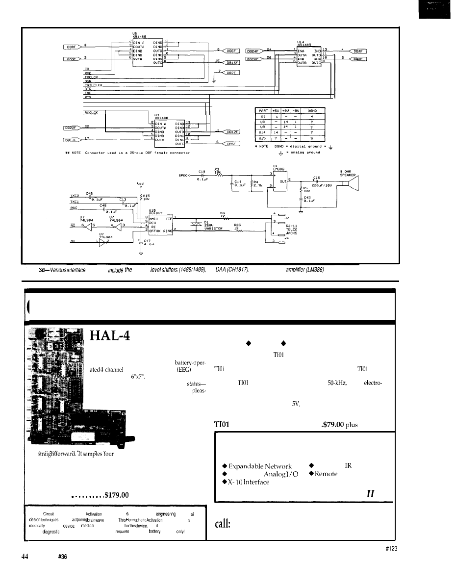
Flgure
elements
HS-232
the
and the speaker
CIRCUIT CELLAR KITS
Sonar
Ranging Experimenter’s Kit
EEG Biofeedback Brainwave Analyzer
Targeting Ranging Machine Vision
The Circuit Cellar
Ultrasonic Sonar Ranger is based on the
The HAL-4 kit is a complete
sonar ranging circuitry from the Polaroid SX-70 camera system. The
electroencephalograph
which
and the original SX-70 have similar performance but the
Sonar
measures a mere
HAL is sensitive enough
Ranger requires far less support circuitry and interface hardware.
to even distinguish different conscious
The
ranging kit consists of a Polaroid
300-V
between concentrated mental activity and
static transducer and ultrasonic ranging electronics board made by Texas
ant daydreaming. HAL gathers all relevent alpha,
Instruments. Sonar Ranger measures ranges of 1.2 inches to 35 feet, has a
beta, and theta brainwave
TTL output when operated on
and easily connects to a parallel
signals within the range of
printer port.
4-20 Hz and presents it in a
serial digitized format that
Sonar Ranger kit.
. . . . . . . . .
shipping
can be easily recorded or
analyzed.
HAL’s operation is
CHECK OUT THE NEW CIRCUIT CELLAR
channels of analog brainwave data 64
HOME CONTROL SYSTEM
times per second and transmits this digitized data serially to a PC at 4800
bps. There, using a Fast Fourier Transform to determine frequency,
amplitude, and phase components, the results are graphically displayed
in real time for each side of the brain.
HAL-4 kit
plus shipping
Trainable
Interface
Digital and
Displays
Call and ask about the HCS
l
The
Cellar Hemispheric
Level detector presented as an
example the
To order the products shown or to receive a catalog,
used in
signals.
Level detector not a
approved
no
clams are made
and should not be used for
(203) 875-2751 or fax: (203) 872-2204
medical
purposes Furthermore, safe use
that HAL be
operated
Circuit Cellar Kits
l
4 Park Street
l
Suite
12
l
Vernon, CT 06066
Issue
July 1993
The Computer Applications Journal
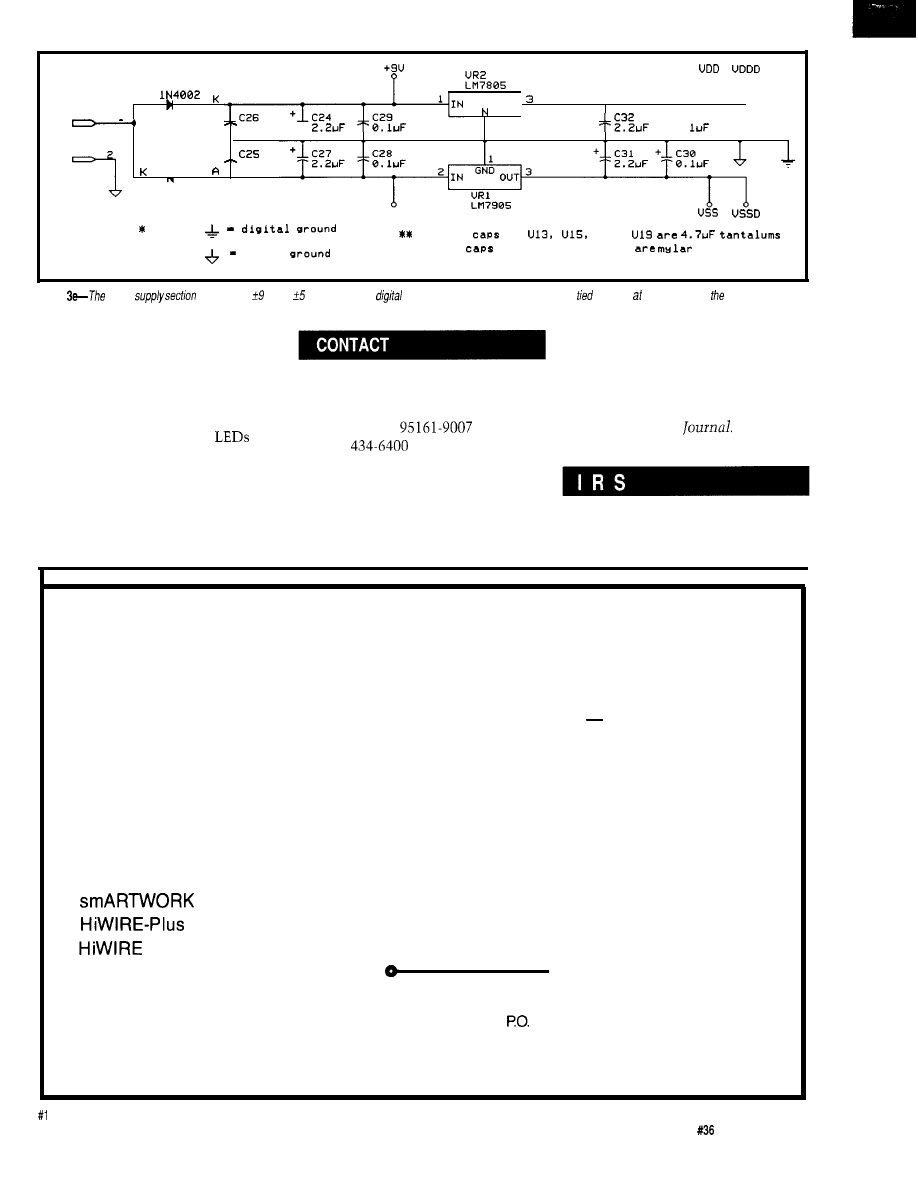
A
1
C R 8
+
OUT
+
J 5
+
c 3 3
2 2 0 0 u F
2
0 .
+
J S
__
lN4002
2 2 0 0 u F
C R 9
- 9 u
N O T E
B y p a s s
f o r
a n d
a n a l o g
B y p a s s
f o r e v e r y t h i n g e l s e
o r c e r a m i c
Figure
power
produces
V and V. Analog
and
power and
analog and digital ground are
fogefher single points at power supply.
modulation, but when you stop to
consider everything else they do, I
think elevating their title to a “com-
munications coprocessor” wouldn’t be
out of line. From now on, I think I’ll
have a little more respect for the work
that goes into making those
blink on my modem as I talk to my
friends in Cyberspace.
q
Michael Swartzendruber is an engi-
neer with experience in network and
Exar Corp.
P.O. Box 49007
2222 Qume Dr.
San Jose, CA
(408)
communications design and Windows
and Macintosh programming. He is
also a Technical Editor for the Com-
puter Applications
Cermetek Microelectronics, Inc.
1308 Borregas Ave.
Sunnyvale, CA 94089
(408) 752-5000
Fax: (408) 752-5004
Special thanks to the people at Exar
for supporting me during this project.
Their help was top notch.
407 Very Useful
408 Moderately Useful
409 Not Useful
EXPRESS CIRCUITS
MANUFACTURERS OF PROTOTYPE PRINTED CIRCUITS FROM YOUR CAD DESIGNS
TURN AROUND TIMES AVAILABLE FROM 24 HRS
2 WEEKS
Special Support For:
l
TANGO.PCB
l
TANGO SERIES II
l
TANGO PLUS
l
PROTEL AUTOTRAX
l
PROTEL EASYTRAX
l
l
FULL TIME MODEM
l
GERBER PHOTO PLOTTING
WE CAN NOW WORK FROM
YOUR EXISTING ARTWORK BY
SCANNING. CALL FOR
DETAILS!
l
l
II
l
EE DESIGNER I
l
EE DESIGNER III
l
ALL GERBER FORMATS
Express
0
Circuits
1150 Foster Street
l
Box 58
Industrial Park Road
Wilkesboro, NC 28697
Quotes:
l-800-426-5396
Phone: (919) 667-2100
Fax: (919) 667-0487
24
The Computer Applications Journal
Issue
July 1993
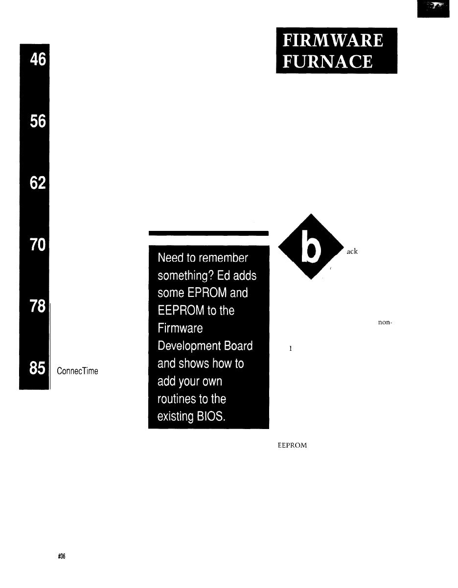
DEPARTMENTS
Firmware Furnace
Ed Nisley
From the Bench
Silicon Update
Embedded Techniques
Patent Talk
Memories Are Made
of This: The ‘386SX
Project Goes Nonvolatile
in February
I pointed out that
“doing firmware” for
the ‘386SX project
didn’t require an EPROM because the
BIOS has all the code you need to boot
a program from disk. That approach
has served us well, but some applica-
tions just cry out for a smidge of
rotating storage.
Compared to the confines of an
803 system, the megabyte of address
space in a PC (we’ll ignore protected
mode’s 16 MB or more for now) seems
limitless. As it turns out, though,
there isn’t that much space left for our
EPROM, and a whole 64K bytes of free
space may be hard to come by.
I’ll start by reviewing the PC’s
memory layout, explore ISA bus
memory timing, then describe the
circuitry needed to add an EPROM or
to the Firmware Develop-
ment Board. With the hardware in
place, a little firmware will let us load
a program into the system so it
becomes a part of the BIOS and runs
whenever the PC starts up.
WHERE DOES MEMORY
COME FROM?
PC’s memory organization pays
homage to The Original IBM PC and
46
Issue July
1993
The Computer Applications Journal
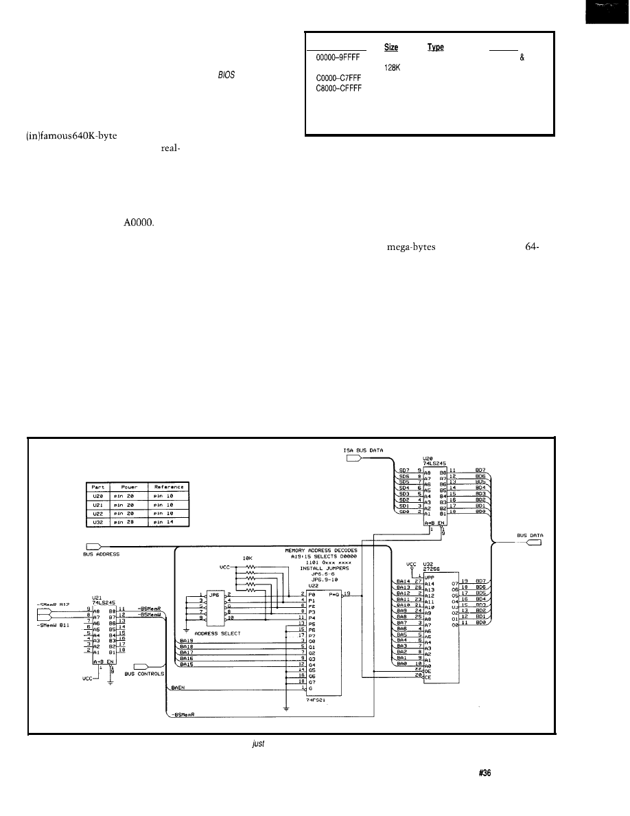
this late date is quibble about the
details because the Big Picture is
thickly encrusted with compatibility
barnacles and impervious to change.
Figure 1 shows the major divisions in
the first megabyte of storage.
its 8088 CPU. The best we can do at
Figure l--The
first
megabyte of PC memory
serves many
different
functions defined both by
the
and by
convention. You should
think
long and hard about
compatibility problems
before you devote a chunk
of
address
space to a
The first and largest chunk is the
block devoted to
nonstandard use!
user programs and data. If your
mode application requires contiguous
RAM, this is as good as it gets. While
there are ways to extend this block,
none are particularly attractive.
Early PCs sported an empty EPROM
The system board BIOS may
occupy either 64K bytes starting at
FOOOO or 128K bytes starting at EOOOO.
Address Ranae
AOOOO-BFFFF
DOOOO-DFFFF
EOOOO-EFFFF
FOOOO-FFFFF
640K
32K
32K
64K
64K
64K
RAM
Video RAM
Video ROM
ROM or RAM
ROM or RAM
ROM or RAM
ROM
Function
Programs data
Video buffers
BIOS Extension
BIOS Extension
BIOS Extension
BIOS Extension
System BIOS
RAM to small buffers and scratchpads.
I/O cards may include ordinary
RAM in addition to the EPROM, but
the cramped address space restricts
The video-RAM buffers occupy
128K bytes starting at
The old
CGA card freed the space below B8000
to get 736K bytes of contiguous user
RAM, but the VGA’s 128K bytes of
buffer renders that trick essentially
useless. Although a VGA in CGA
mode can release the space below
B8000, simply changing back to VGA
mode will lock up the system.
Of course, if your application
doesn’t use video, you can yank the
card and devote the address space to
whatever you’d like. The Bad News is
you can never, ever, install a video
card. That seems a shame given the
utility of built-in, BIOS-supported,
standard video, but it’s your call..
socket or two on the system board, but
relentless cost reduction eliminated
that nicety in short order. If your PC
doesn’t have BIOS code at EOOOO you
can use that address space for your
own purposes.
Some I/O cards-notably video
adapters, exotic hard disk controllers,
and network adapters-include
EPROMs that modify, extend, or
replace some system board BIOS
functions. The BIOS scans the 128K
bytes of address space between COO00
and EOOOO to find these EPROMs and
execute their startup code during
power-on initialization. Fortunately
for us this entire process is well
defined and essentially magic free.
The history of LIMS EMS cards shows
what can be done when you’re desper-
ate for more RAM: bank-switching 32
of storage through a
kilobyte slot isn’t pretty, but it was
the only way to do it when it needed
doing.
Embedded applications have more
freedom to chop up the lower 640K
bytes, so, when we need huge buffers,
they need not fit between the video
buffers and the system BIOS. Some
applications can make use of the vast
extent of RAM beyond the lower
megabyte, even when running in real
mode, and we’ll look at that later.
The Firmware Development Card
will include either 8K bytes or 32K
Figure
2-Adding an EPROM to the Firmware Development Board involves
some buffers and a decoder.
The Computer Applications Journal
Issue
July 1993
4 7
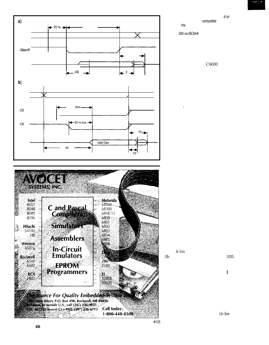
Address
509 ns min
min
\
30 ns max
Data
Valid Data to CPU
ns
max
mm
Address
\
200 ns
-
-
,
\
55
max
Data
200 max
0
min
Figure 3-a) Signals
and timing involved in an
ISA
bus memory read access are
with cards
designed for original IBM PC and are painfully slow
by contemporary standards. b) Timings show the read
cycle for a
EEPROM, but they
are
typical of EPROMs as well. The bus buffers shown in
the schematic truncate the rather long maximum data
hold time.
bytes of storage mapped into the PC’s
address space between
and
CFFFF. While the decoding circuitry
allows you to plunk it at any other
address in the first megabyte, I think
you can see why the actual choices are
rather restricted.
Before we link up with the BIOS,
though, we must get the memory
running..
CONFRONTING THE ISA SLOWS
Not only do ISA bus barnacles
determine the memory layout, they
also set the memory access time.
You’ve probably noticed that high-end
PCs now sport “local bus” connectors
for memory and high-bandwidth I/O..
after this column, you’ll know why.
Figure 2 shows the falling-off-a-log
simple circuitry needed to put an
EPROM on the Firmware Develop-
ment Board. The ‘LS245 buffers isolate
the bus data and control lines, the
F521 activates the EPROM’s -CE input
when the CPU reads or writes a byte
in the desired address range, and the
EPROM holds the data.
The tradeoff for this simplicity is,
as usual, performance. Because the
EPROM is only eight bits wide, the
CPU must fetch one byte at a time.
The ISA bus defaults to the same
achingly slow six-cycle 720 ns access
for memory as it does for I/O, with the
results shown in Photo
1.
Figure 3a shows ISA bus timings
for an
memory access and Figure
show typical access times for a
ns EPROM or EEPROM. It’s easy to
see that the data will be ready long
before the end of the bus cycle, so
won’t go through the same analysis as
I did with the I/O ports.
It seems obvious that we need to
reduce the bus cycle time, but appear-
ances can be deceiving.
There are two ways to speed up
ISA bus memory accesses. You can use
a pair of EPROMs (or a pricey
48
Issue July
1993
The Computer Applications Journal
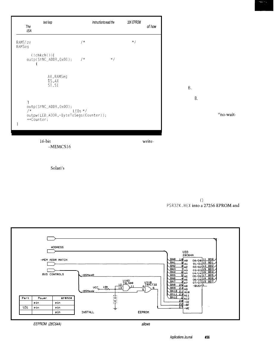
Listing l--This
uses a single REP LODSB
entire
address
space.
elapsed loop time, measured either by stopwatch or oscilloscope, gives a good indication
fast the
bus can handle memory accesses.
= 0x8000;
repeat for 32K block
= NV-SEGMENT;
Counter = 0;
while
scope sync
asm
MOV
CX,RAMSize
set up count
PUSH DS
MOV
set up address
MOV
XOR
REP
LODSB
POP DS
show count on FDB
part) to provide
accesses and add
circuitry to activate
to get
three-cycle memory accesses. If that
isn’t good enough, you can attempt to
activate SRDY fast enough to get a
two-cycle access, but
book is
replete with cautions and compatibil-
ity hazards.
It turns out, though, that there is a
better way that not only makes the
bus access time irrelevant, but doesn’t
involve any extra hardware. The
“ROM shadowing” feature of most
current system boards copies the
EPROM contents into RAM, disables
the EPROM, maps the RAM to the
The BIOS does all the copying and
remapping during the power-on reset
sequence, so by the time your code
gets control, the EPROM is out of the
picture. The system board circuitry
runs much faster than the ISA bus, so
operations that depend on EPROM
data get a corresponding boost.
Listing 1 shows a section of
MEMTEST. C that reads the 32K block of
storage with REP LODSB in a tight
loop. It takes 33 ms per loop with
shadowing disabled, or about 960 ns
per LO D S Enabling ROM shadowing
cuts the loop to 7.3 ms, or about 210
ns per L 0 D S Simple division: ROM
shadowing reduces the elapsed loop
time by about 80%.
Even if you could get a
state” ISA bus interface running, it
would still take 240 ns just for the bus
access. To judge from my logic ana-
lyzer traces, each REP LODS B adds two
EPROM’s address range, and
bus cycles to the minimum required to
protects it. Poof: fast EPROM made
fetch the data, so even an optimized
possible by cheap RAM!
interface would take 480 ns per byte.
Contrary to popular opinion, this
There you have it: a four-chip,
shadowing has nothing to do with the
warp speed, no hassle EPROM storage
magic made possible by the 386 CPU’s
system for your embedded system.
protected-mode memory management
Ain’t science grand?
hardware. It’s entirely a function of the
The MEMTEST. C program has the
system board LSI hardware, so your
test routines I used to get the memory
programs continue to run in real mode.
working, including a hex file with 32K
The relocation hardware may chop up
bytes of pseudorandom numbers from
the memory above the first megabyte
Micro-C’s r a nd
function. Burn
enough that protected mode operating
systems have trouble using it, but
run MEMTEST
to
read and
verify
it...
that’s a completely separate design
that should give you confidence that
issue.
your circuit works!
BUS DATA
BUS
Rsf
U16
1 4
7
14
7
u 3 3
Pin
2 8
14
J U M P E R T O
W R
I T E
-
P R
O T E C T
Figure 4-Using
an
as opposed to an EPROM (27256) requires less park, which
for some extra space on the Firmware Development Board.
The Computer
Issue
July 1993
49
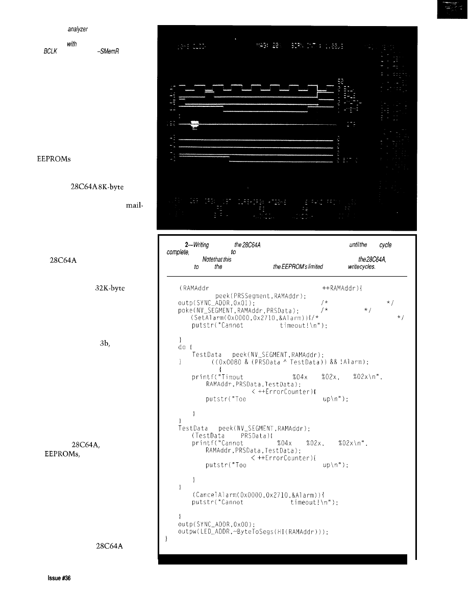
Photo l--The logic
trace shows what
happens when the CPU reads a single EPROM byte.
The access begins
the rising edge of BALE and
ends six
cycles later when
goes high.
WRITING TO EEPROM
There are times, however, when
an EPROM is not the right hammer for
the job. Whether you have frequent
code changes, need nonvolatile data
logging storage, or just don’t want to
hassle with an EPROM programmer,
an EEPROM may solve your problem.
come in several
different flavors, but for our purposes
they’re all pretty much alike. I’ll use
the Microchip
EEPROM as an example because it’s
readily available from the usual
order sources. Feel free to use some-
thing else, but remember the address
space limits before you spring for a
megabyte part!
Figure 4 shows the changes needed
to put a
in place of the 27256
EPROM. Because the EEPROM has
only 8K bytes, the CPU will see four
identical copies in the
address range decoded by the F52 1
comparator. You can add SA14 and
SA13 to the comparator or just ignore
the ghosts, which is what I did in the
code for this column.
As shown in Figure
reading an
EEPROM is just like reading an
EPROM: the data is ready in plenty of
time. There are no special tricks
needed to get data from the part.
Writing, on the other hand, is
more complex because the EEPROM
requires up to 1 ms (that’s 1000
microseconds, one million nanosec-
onds, or about 63
miles
on Admiral
Hopper’s scale) to erase and reprogram
each byte. The
as with all
useful
has internal latch
and timing circuitry to relieve the
CPU of the details, but it cannot
accept a new byte until the previous
write cycle is completed.
If you have other things to do, you
can ignore the EEPROM for at least a
millisecond after each write; the
timers on the Firmware Development
Board are ideal for measuring this kind
of delay. However, the
includes a polling mode that signals
Listing
a byte info
is easy, buf you must then poll the chip
write
is
which can fake up one millisecond. The code must also include error handling for timeouts and
defective parts.
will work perfectly wifh a standard static RAM in place of
which is
a good way debug code without using up
number of
for
= 0x0000: RAMAddr != 0x2000;
PRSData =
mark the write
start it
if
error after 10 ms
set BIOS
break:
=
while
if (Alarm)
programming
to
is
if (MAX-ERRORS
many errors, giving
break;
=
if
!=
program
to
is
if (MAX-ERRORS
many errors, giving
break:
if
cancel BIOS
break;
50
July1993
The Computer Applications Journal
Contents
0000
55
0001
AA
0002
xx
EB 01
0005
ss
0006..
code
Definition
First signature byte
Second signature byte
Overall length in
units
JMP SHORT
(to 0006)
Checksum
BIOS extension code
Figure
The
examines
of each block between
and
for
code. If first two bytes contain a valid
signature and block checksums zero, the
executes a FAR CALL
offset 0003 so extension can initialize itself.
signature, length
byte, and valid code at offset 0003 are required;
structure of the code
block is not specified. The diskette EEPROM loader described column
assumes
checksum is located at offset 0005.
when the write cycle is finished: if
you read the address you just wrote,
the chip inverts bit 7 while it’s busy.
Bits O-6 are undefined, so you must
them off before comparing the
bytes.
Typical writes are much faster
than
1
ms, so you can save a consider-
able amount of time monitoring the
status. M EMT EST's EEPKOM program-
ming loop
about four seconds to
write all SK bytes, so the average time
is well under 500
Listing 2 shows how
this
After writing
the byte using Micro-C’s
po ke
function, the
code sets up a IO-ms
timeout and enters a
loop waiting for bit 7 to
match the
poke
bit.
After the exclusive OR
returns zero (or after the
timeout), the code
for errors before
continuing with the
next byte.
Note that you need
one additional read after the
reports that it’s not busy, as the data
may not valid immediately after bit
7 changes.
The
EEPKOM has much
the same
as an
static
and I
strongly
that
you use a RAM instead of an EEPKOM
until you are entirely sure your
hardware and code are up to par. The
specs say it is good for
write cycles, but that
out to
perhaps ten seconds at full throttle.
For example, one of M EMT EST's
routines is a tight write loop so you
can look at the control signals on a
scope. This will slaughter an innocent
in short order, so careful
what’s in the socket.
Pin 26 is
on
RAM
S
, but
is not connected on
so you
can simply wire it high. Pin 1 is the
-Busy output, but it’s not
connected in
so you
don’t have to worry about it, either.
The process is similar for
the
but do
match up the data sheets before doing
anything silly.
Being able to program an EEPROM
in the system is an advantage, but it’s
distressingly easy to clobber your
precious code or data with an errant
write. If you plan to use an EEPROM
as a programmerless EPROM, the
jumper and gates shown in Figure 4
provide simple, manual
protec-
tion.
Even if (you think) your code is
completely under control, other
routines may write into “your”
The BCC52 controller continues to be
Micromint’s best selling single-board com-
puter. Its cost-effective architecture needs
only a power supply and terminal to become
a complete development system or
board solution in an end-use system. The
BCC52 is programmable in BASIC-52. (a
fast, full floating point interpreted BASIC). or
assembly language.
The BCC52 contains five RAM/ROM
sockets, an “intelligent” 27641128 EPROM
programmer, three
parallel ports, an
auto-baud rate detect serial console port, a serial printer port, and much more.
PROCESSOR
CMOS processor w/BASIC-52
Much morel
Console
232
Three
parallel ports
EXPANDABLE1
12 BCC
boards
expandable
on-board memory sockets
EPROM
Controller board
BASIC 52 and SK RAM
$ 1 8 9 . 0 0
Low-power CMOS
the BCC52
$ 1 9 9 . 0 0
BCC51
to
C
temperature
$ 2 9 4 . 0 0
Low-power CMOS expanded BCC52
RAM
$ 2 5 9 . 0 0
CALL FOR OEM PRICING
MICROMINT, INC.
Canada
9426
Welcome’
1 7 9 2 1 R o w l a n d S t r e e t
City of Industry, CA 91748
T e c h n i c a l S u p p o r t :
VISA
912-9864
MASTERCARD
and DISCOVER
_ l-800-669-4406
R C - 9 9
RF Transmitter
R e c e i v e r S e t
12 bit address 6 address 4 data.)
‘93 SPRING CATALOG
DRAM memory.
Encoder Decoder
Radio Communications:
Motorola Spirit Radios.
Digital Voice Modules.
RF Transmitters
Security:
Auto Alarms and Accessories
X-IO Home
Tools:
Soldering Irons.
EPROM Erasers.
Fluke DMM.
Industrial PC.
EPROM Programmers.
Ultrasonic Measuring
Prototyping
Full
of Syntax PCB
Batteries:
Alkaline
Ni-Cad.
Sealed Lead Acid.
Pocket PC Ref for
Button Cell
The Computer Applications Journal
Issue
July
1993
51
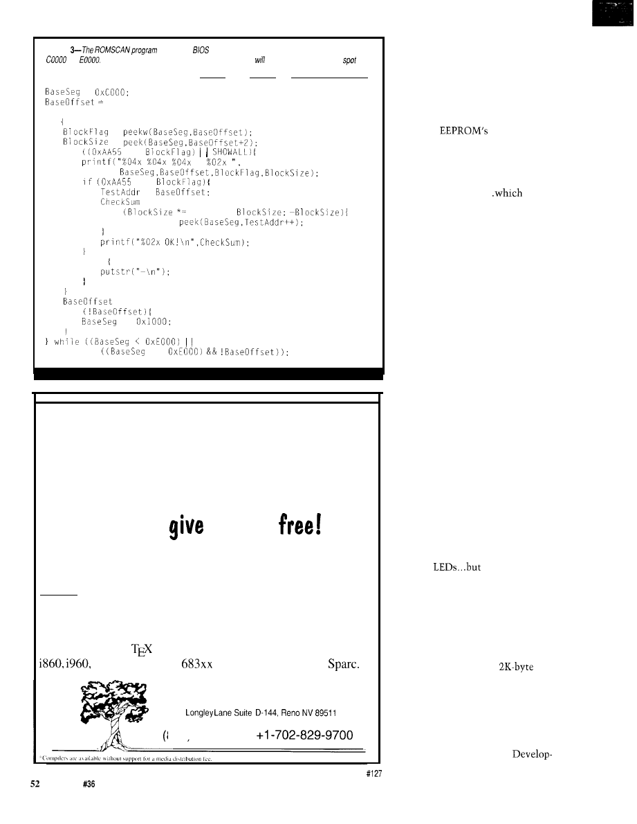
Listing
mimics the
signature search through the address space between
and
It displays the header for valid extensions, which he/p you identify a vacant
for
the Firmware Development Board’s nonvolatile memory.
=
0x0000;
do
=
=
if
==
==
=
= 0;
for
0x0200;
Checksum +=
else
+= 0x0200;
if
+=
==
WHY
are our cross
compilers so inexpensive???
Because we
them away
We base our cross compilers on the GNU C/C++ compiler from the
Free Software Foundation.
We provide you with one year of
support*, and give you a ready-to-run cross compiler with complete
source for DOS, Windows, OS/2 2.0 or UNIX for $495 per year.
Or, get the extended support package for $895, which includes
GNU Emacs and make, the CVS and RCS source code control
utilities,
and the
typesetting system. Targets include i386,
Motorola 680x0,
and 88000, MIPS and
Hundred Acre Consulting
5301
800) 245-2885
address space. For some reason the
BIOS setup code in my ‘386SX writes
AA every 2K bytes or so throughout
the address range: an unprotected
EEPROM won’t survive a reconfigura-
tion.
Installing the write protect jumper
forces the
-WE line high,
so any writes will simply fail. M EM
TEST's loop reports a timeout error
after 10 ms, but any other code will
simply conclude that the EEPROM is
an unchanging ROM..
is
exactly what we want.
In next month’s column, I’ll add a
software-controlled write-protect bit
for the battery backed RAM, but a
manual jumper is enough for now.
That circuitry will need an HCT32,
which is why I used it here.. .it won’t
go to waste!
THE BIOS CONNECTION
Now that the Firmware Develop-
ment Board has a smidge of nonvola-
tile memory, we can bolt code onto
the System Board BIOS to run after
each hardware reset. This opens the
door to “diskless systems” that boot
with no mechanical motion.
Actually, given the limited space
available (what can you do in 32K
bytes these days?], it’s more likely that
the (E)EPROM will hold key hardware
interface routines rather than the
whole embedded application. The rest
of the code can be on diskette or, with
a little ingenuity that I’ll get into in a
few issues, be downloaded through the
serial port as needed.
In any event, we’ll start small:
once again the end result will be a few
blinking
the weight of
knowledge behind them should make
you feel good!
As I mentioned earlier, the BIOS
scans through the memory between
COO00 and EOOOO on power up to find
BIOS extensions. It’s looking for the
distinctive signature shown in Figure
5: 55 and AA bytes on a
boundary with a valid checksum over
the block of storage specified by the
length byte.
Listing 3 shows how the search
works. I wrote ROMSCAN. C to examine
my system’s address space so I knew
where to put the Firmware
Issue
July 1993
The Computer Applications Journal
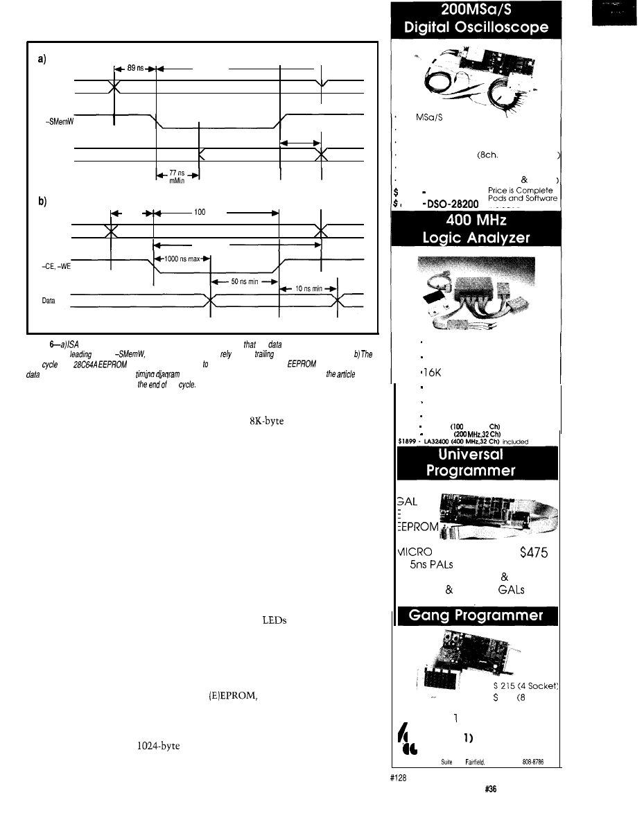
Address
min
509 ns min
30 ns max
Data
25 ns min
Valid Data from CPU
Address
10 ns
ns min
min
5 0 n s m i n
Figure
bus memory write accesses are similar to reads. Note
fhe
may not be valid for quite a
while after the
edge of
so the destination must on the
edge for precise liming.
write
for a
is essentially identical a standard
RAM, but the
cannot accept more
for about a millisecond. This
shows the signals for the first part of the process;
text
describes
how the firmware detects
the
ment Board’s nonvolatile memory. It
turned out that the only BIOS exten-
sion was a 32K EPROM on the VGA
card at COOO:OOOO, but your system
may have other ROMs on other cards.
ROMSCAN
cannot identify anything
that isn’t a ROM, so if your system
includes EMS cards, network adapters,
or other oddities [you aren’t doing this
on your real PC, are you?) it won’t
show their RAM buffers or other
ROMs. On the other hand, neither can
the BIOS, so we’re even.
When the BIOS finds a valid
extension, it does a FAR CALL
to
the
instruction starting at offset 0003. It is
your responsibility to put the first byte
of your routine at that address! When
your code is done initializing itself, it
should return control to the BIOS with
a RETF (far return) instruction. The
BIOS then seeks out other extensions
and, after calling all of them, it
continues with the normal disk boot
process.
The length byte counts in units of
512 bytes starting
from offset 0000, so
a length of 02 indicates a
block. If your routine is only 800 bytes
long you must still use a length code
of 02. An
EEPROM with a
single extension will use a length code
of 10.
The checksum covers the entire
block, but the BIOS does not care
where you put the checksum byte
itself. As long as the (length x 512)
bytes starting at offset 0000 add up to
zero, the BIOS is happy. The code for
this column puts the checksum in
offset 0005 just after a short jump, but
that is entirely my convention.
Listing 4 shows a simple BIOS
extension with two useless functions.
If the low-order DIP switch on the
Firmware Development Board is ON,
it blinks the
forever to indicate
that it’s in control. If the switch is
OFF, it turns on both decimal points
and returns to the BIOS to continue
the normal boot sequence.
Before loading this into the
we must compute the
checksum. I modified the diskette boot
loader from issue 3 1 to perform both
functions on a system with the
Firmware Development Board in-
stalled. After reading the file from
200
sampling rate
PC-BASED INSTRUMENT
2 Analog channels
8 Digital channels
logic analyzer
125MHz Single shot Bandwidth
4K samples/channel (analog digital:
1599 DSO-28 100
1999
included
up to 128 channels
up
to 400 MHz
samples/channel
Variable threshold
8 External clocks
16 level triggering
$799 IA12100
MHz,24
Price is Complete
$1299 LA32200
Pods and Software
‘AL
PROM
‘LASH
4 MEG EPROM (8 16 bit)
22V 10 26CV 12
Free software updates on BBS
299 Socket:
Up to MEG EPROMS
Call
( 2 0 808-8990
Link Computer Graphics, Inc.
369 Passaic Ave.
100,
NJ 07004 fax:
The Computer Applications Journal
Issue
July 1993
53
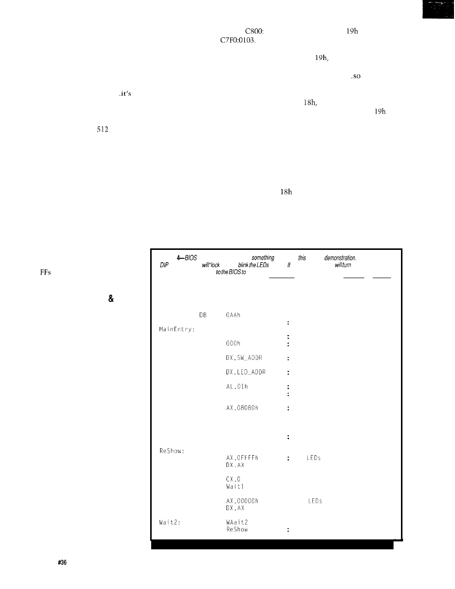
diskette as usual, LOADEXT writes it
into the EEPROM, computes the
checksum, and stuffs that into offset
0005.
Once LOADEXT is finished, install
the write-protect jumper, pop the
diskette, and hit the reset button to
start your new BIOS extension..
that easy!
One gotcha that is painfully
obvious in retrospect: if your code
doesn’t fill a multiple of
bytes, the
checksum must include whatever junk
is in the last block. You cannot
compute the sum on just your code,
because the length byte includes more
than that. Listing 5 shows the code
needed to figure the EEPROM
checksum.
For EPROMs, of course, the
unprogrammed bytes are FF, so you
can compute the checksum correctly
without actually having to handle
those bytes one by one. In fact,
because the hex file doesn’t include
the unprogrammed bytes, you’ll have
to use the length to figure out how
many
the BIOS will include in its
calculations.
BIOS EXTENSION HINTS TIPS
Much of the Firmware Develop-
ment Board’s hardware will be sup-
ported by BIOS-like routines in the
nonvolatile memory we just got
working, but that code will appear in
separate columns after we get the
hardware thrashed out. Many of you
are champing at the bit, though, so I’ll
hit the high spots here.
First of all, I don’t think it’s
practical to write BIOS extensions in
C. After all, we have a pile of stuff to
fit into a very small bag.. this is a job
for assembler code! While I’m sure it’s
possible to modify the Micro-C startup
code to run from the EEPROM, it
requires Small model and some
additional code. Dave’s comments in
the startup code files should be helpful
if you want to try it.
The code in COM files produced
by PC linkers starts at offset 0100, but
the BIOS extensions must begin at
offset 0. Probably the easiest way to
relocate the code is to subtract 0010
from the CS register and use an
indirect branch to increment IP by
0100. For example, the byte at
0003 is also located at
It’s
the same trick I used in the boot sector
loaders, so check there to see how it
works.
The BIOS calls all of the exten-
sions after it’s set up all of the inter-
rupt vectors but before it attempts to
Any RAM needed by the EEPROM
boot from diskette. Your initialization
code must be in the lower 640K and
you must ensure that the routines
don’t step on each other’s storage.
code can hook any interrupts that it
Remember that the DOS memory
will need to regain control later on:
allocation routines don’t exist! The
BIOS keeps track of the memory size,
so you can allocate space by reducing
timer ticks, serial ports, whatever.
that number. In effect, your data will
lie beyond the end of memory, but
only because you’ve moved the “Dead
End” sign up a few feet.
In particular, Int
is called after
all the extensions are initialized to
handle the disk boot load. If you
capture Int
your code regains
control just before the BIOS expects to
boot from the diskette..
you
can
boot from, say, a program loaded over
the serial port.
According to my references Int
is not supported on all clones, as it
was originally used to start good old
IBM Cassette BASIC. I’ll give it a try,
Int
on the other hand, is
but some BIOS spelunking on your
supposed to be called after Int
concludes that there are no bootable
own system is in order to be sure it
diskettes or hard disks. By capturing
this interrupt, you have the option of
booting from diskette to update the
works the way you want.
firmware (for example) while running
without a diskette the majority of the
time.
Listing
extensions normally do
useful, but
is just a
If the low-order
switch is ON if
up” and
forever. fhe switch is OFF if
on fhe LED
decimal points and return
continue fhe normal boof sequence.
CODESEG
STARTUPCODE
DB
DB
Booter:
Onward:
Waitl:
JMP
DB
MOV
IN
MOV
TEST
JZ
MOV
NOT
OUT
RETF
MOV
OUT
MOV
LOOP
MOV
OUT
MOV
LOOP
JMP
055h
SHORT Booter
AX,DX
Onward
AX
DX.AX
cx,o
; signature
length in units of 512 bytes
force two-byte jump
zero checksum until loaded
should we run?
set up for display
low switch ON?
zero is yes, so stay here
show we were here
; just decimal po
and return to BI
all
go off
; all
go on
continue forever
nts!
OS!
5 4
issue
July 1993
The Computer Applications Journal
Listing
5-The B/OS extension checksum includes
in the defined block. This routine, taken from
the
boot sector EPROM loader, computes checksum based on the extension’s code plus
whatever is in fhe last block beyond end of fhe code. writes fhe result at
0005 in
which must be a zero in disk
MOV
MOV
XOR
MOV
MOV
MOV
MUL
BX
MOV
MOV
MakeCSum:
LODSB
SUB
BH,AL
LOOP
MakeCSum
aim at EEPROM
beginning of block
pick up length code
set high byte
convert to bytes
in AX
set up for loop
set up checksum
pick up data byte
tick checksum
over entire block
MOV
AL,BH
set up checksum
MOV
address
CALL
do it
RELEASE NOTES
The code on the BBS this month
includes the source and hex files for
everything you’ve seen here, as well as
modifications to the
F I RMDEV H
and
.ASM
files mentioned in the past. The
EEPROM boot loader and
EXTDEMO
BIOS extension are written with
Borland’s TASM, but everything else is
in Micro-C.
Be careful with diskettes contain-
ing the
LOAD E XT
boot loader, because,
unlike
from issue 31, they
require a Firmware Development
Board. If you boot them in an ordinary
system, it will seem to hang without
any error indication. It won’t damage
anything, but it can be pretty scary.
By the time you read this, we
should be settled in North Carolina.
I
hope all my machinery makes it
through the move!
Ed Nisley, as Nisley Micro Engineer-
ing, makes small computers do
amazing things. He’s also a member
of
the Computer Applications
engineering
staff.
You may reach him
on CompuServe at
or
through the Circuit Cellar BBS.
Software for this article is avail-
able from the Circuit Cellar BBS
and on Software On Disk for this
issue. Please see the end of
in this issue for
downloading and ordering infor-
mation.
410 Very Useful
411 Moderately Useful
412 Not Useful
CIRCUIT CELLAR PROJECT
SPECIAL SUBSCRIBER OFFER
r
For
TOP
projects from the Circuit Cellar Design Contest
NEW
projects tutorials
Something for every interest
Order both volumes and save!
(regularly
each)
VISA,
or International Postal Money
Order (U.S. funds drawn on U.S. bank only)
Circuit Cellar
File
4
Park Street
Vernon, CT 06066
Tel: (203) 875-2 199
Fax: (203) 872-2204
domestic
Please add $6
copy for delivery to
via U.S.
Mail;
add $8 per copy for other
addresses
via U.S.
Use your own PC and
Ethernetnetwork
adapter (in most cases)
Display
Assembler
24-Hour BBS and 6 Months Free Software Updates
Inc.
604 Daniel Webster Hi hway, Merrimack New
Voice:
FAX:
BBS:
The Computer Applications Journal
Issue
July 1993
5 5
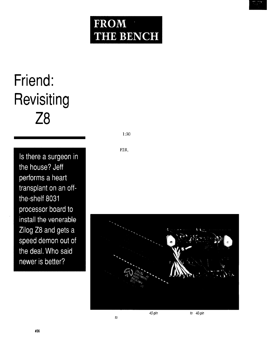
Breathing
New Life
Into an Old
the
Jeff Bachiochi
0
onight the space
shuttle Discovery
is once again keeping
its silent vigil over the
Earth, circling once every 93 minutes.
A hydrogen valve sensor on one of the
liquid-fuel engines refused to signal a
closure, scrubbing the launch set for
last night. These
A
.
M
.
launches are
unaccommodating for us first shifters.
I view the “NASA Select” broad-
casts on Satcom
Transponder 13.
It is offered to all cable systems
without charge, though few of them
actually carry it. Twenty-four-hour
pre-to-post flight coverage preempts
the normal four-hour blocks of
educational science-oriented program-
ming. This flight, STS-56, is investi-
gating both ozone depletion and solar
flare activity.
No, this is not an infomercial.
However, I do strongly believe that the
U.S. would not have today’s level of
technology if we hadn’t invested in the
space program 30 years ago. And it
would be a serious mistake to stop
investing now (soap box mode off).
The “red crew” is preparing to
exercise the robot manipulator arm, as
my telephone starts ringing. I decide to
let it ring. “One of the kids will pick it
up,” I think to myself. The ringing
eventually stops. As I refocus my
attention on the live shot of the Earth
taken through the shuttle bay window,
I’m handed the portable phone.
“Hello,” I mumble while staring
at the view of the Earth from above.
“This is Johnson Space Center calling.
Is this Jeff Bachiochi?” Surprised by
this unlikely statement, I stammer
“Huh. What? Yes! Wait, who is this
really?” The caller assured me he was
from Houston and explained how he
had called directory assistance starting
with Circuit Cellar’s office exchange
and then continued to call neighboring
exchanges in a spiral pattern until he
located me. Well, he had my attention.
“We’ve got a serious problem here
and if we can’t solve it this weekend,
we want to fly you down to Houston
on Monday morning.” I felt the strain
in his voice. “I want you to talk to the
project engineer.”
For the next 30 minutes we
discussed the system they were
developing for use on Space Station
Freedom. It had been about ten years
Photo l--The
processor adapter consists of a
component carrier wired a
socket Stranded wire was
used in an attempt avoid breakage when the pieces are flexed.
5 6
Issue
July 1993
The Computer Applications Journal
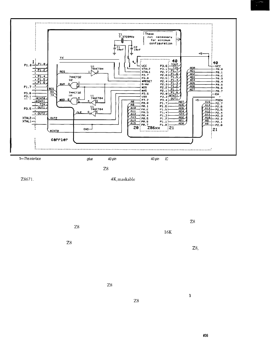
RX
P1.l,
P 1 . l
P1.2 .
P 1 . 3 ,
P I . 3
P 1 . 4
PI.5 .
P 1 . 6
P 1 . 7 ,
RESET
P 3 . 2
P3.3 .
P 3 . 4
.
T O U T ,
P 3 . 6
‘PO.O
ALE
ALE
P3.7 .
uss
2 0
c o n n e c t i o n s
. . . . . . . . . . . . . . . . . . . . . . . . . . . . . . . . . . . . . . . . . .
chip
8052 socket
Figure
circuit adapter requires some extra
logic and a
chip carrier plugged into a
DIP socket.
since I had worked at any length with
that system, which was based on the
Zilog
Fortified with a barrage
of diagnostic tests to perform and
signal points to investigate, we parted
phone lines. I assured them I would be
around most of the weekend if they
needed to confer again.
STILL CRAZY AFTER ALL THESE
YEARS
The Zilog 28671 is part of the
family of processors. Masked into the
part is a 2K tiny BASIC interpreter. As
a subset of Dartmouth BASIC,
BASIC/Debug allows the user to easily
examine and modify any memory
location or I/O port as well as do bit
manipulation and logical operations.
For faster execution, machine language
routines can be called from BASIC as
subroutines or functions.
Unlike some of the newer micros,
the 28671 can operate without
external RAM. Programs using few
variables can share the internal stack
space for variable storage, which saves
real estate and parts cost. If external
RAM is available, it is automatically
used for variable storage.
The family of microcontrollers
dates back to the late ’70s and boasts
both 2K and
ROM and
protopack parts. The protopack parts
actually accept an EPROM piggyback
style as opposed to a windowed
programmable part, making it much
easier to use. The preprogrammed part,
the 28671, incorporates “Tiny BA-
SIC,” which in those days opened a
whole new world for hardware junkies.
Imagine being able to test out your I/O
without having to sit down with an
assembler.
Along with the introduction of an
expandable microcontroller system
based on the 28671 (one of Steve’s
early BYTE projects), another program-
ming language was gaining momen-
tum: Forth. Back in those days, we
were crazy enough to try just about
anything, including developing and
masking a with a Forth compiler
(based on the Forth-79 standard); 4K
Forth anyone!
I’ve always liked the
because of
its register-oriented architecture. The
internal register file consists of 124
general-purpose registers, 16 CPU and
peripheral control registers, and 4 I/O
registers, each eight bits wide. Any of
the general-purpose registers can be
used as an accumulator, address
pointer, index, data, or stack register (a
very flexible arrangement). Using
register pointers and working register
groups allows for fast context switch-
ing and shorter instruction formats.
USED 2K RAMS
That first system made used
two 2K RAM chips, and, like my first
TRS-80 Model 1, at the time I
thought I would never use all that
RAM. But now, having rekindled my
interests in the
I was having
second thoughts about pulling out that
system again with its memory limita-
tions. What I really needed was to slip
that processor into a newer chassis.
THE HOUSE THAT JACK BUILT
I like recycling. Why can’t I reuse
an existing design but with different
components? mean, not new parts in
a new design, but different parts in an
unmodified, preexisting design? Con-
fused? Well, hang on a second, and I’ll
try to clear it up for you. Remember
the RTC52 and I/O boards I presented
The Computer Applications Journal
Issue
July 1993
5 7
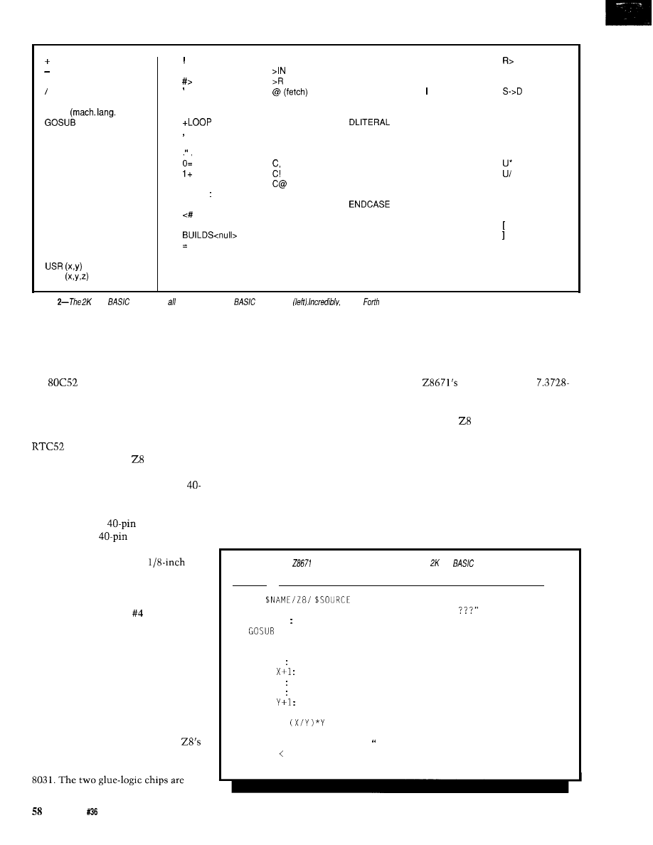
l
AND
GO@
call)
GOT0
IF
INPUT
LET
LIST
NEW
PRINT
REM
RETURN
RUN
STOP
THEN
USR (x)
USR
(store)
>=
# (sharp)
(tick)
+
AGAIN
+!
ALLOT
AND
(comma)
BASE
_
BEGIN
(dot-quote-space) BLK
2
DROP
CASE
C-MOVE
COLD
<
COMPILE
CONSTANT
COUNT
CR
H.
CREATE
HERE
D+
HOLD
D.
DABS
IF
DIGIT
IMMEDIATE
J
DNEGATE
KEY
D O
LEAVE
DOES>
LITERAL
DROP
LOOP
DUP
MIN
ELSE
NEGATE
EMIT
NUMBER
OF
EXECUTE
OR
EXPECT
OVER
FIND
PAD
FORGET
QUIT
(R-FROM)
REPEAT
ROT
SIGN
SMUDGE
SPACE
SWAP
THEN
TYPE
UNTIL
WHILE
WORD
XOR
(left bracket)
(right bracket)
Figure
Tiny
implements of the most useful
commands
the 4K
implements four times as many commands (right) in on/y twice
the space. Program execution is also much faster.
in “From the Bench” in the April/May
‘89 issue of Circuit Cellar INK! I’ve
used these boards over and over again
since then. Well, let’s just pull out that
old
processor and pop in the
Z...er, wait. That won’t work-at least
not yet anyway.
Refer to Figure 1 to see how you
can make an adapter to retrofit your
(or any other 803 I-based
system) for use with a
processor.
You can make this interface circuit fit
in the same space occupied by one
pin chip by using stacked sockets to
hold the “translation circuit.” To do
this, start with a
chip carrier
plugged into a
DIP IC socket
(this way they will remain aligned
with one another). Drill a
hole centered between the rows of pins
at each end of the socket. Now
separate the socket and carrier from
each other. Two short nylon
standoffs are used to hold the socket
(which the Z8 will plug into) above the
carrier (which plugs into the 803 1
socket on the circuit board). All the
interfacing circuitry is sandwiched
between the carrier and the socket.
The finished interface circuit adapter
appears in Photo 1.
Three inverters and two AND
gates are needed to transform the
output signals into those which
closely correspond to those of the
super glued upside down to the top
surface of the chip carrier.
I
stuck
small labels on to their exposed bellies
to identify which was which and
where pin 1 was located. Simple tricks
like this one tend to greatly improve
your chances for continued sanity later
on. I used wire-wrap wire to connect
the appropriate pins of the glue-logic
chips to the pin-leads on the chip
carrier, but when wiring the “straight
through” connections between the
carrier and the DIP socket, I selected
the smallest size stranded wire I could
find. This method improved the
flexibility between the two parts
which would be opened and closed a
number of times like a book while I
was testing this rig. I did not want
brittle connections to cause me grief.
To make swapping even simpler,
the
DIP socket has a
MHz crystal tied directly to it. The
crystal on the RTC board is not used
to drive the and those pins are left
unconnected.
USE THE FORCE
The ROM (BASIC/Debug and
Forth) versions of these parts read
address %FFFD on reset to determine
the console data rate. This value can
be read from the EPROM or an I/O
port depending on which is mapped
Listing
l--The
BASIC/Debug chip contains an internal tiny
interpreter that speeds
program development.
1 REM
10 PRINT "Print prime numbers between 1 and
20 INPUT N REM Get Maximum Number
30
100
40 PRINT “End of run"
50 STOP
100 X = 0 REM Initialize Number
110 X =
REM Next Number
120 Z = 0 REM Reset PRIME Flag
130 Y = 1 REM Initialize Check
140 Y =
REM Next Check
150 IF Y >= X THEN GOT0 180
160 IF X =
THEN Z = 1
170 GOT0 140
180 IF Z = 0 THEN PRINT X: is a prime number"
190 IF X N THEN GOT0 110
200 RETURN
Issue
July 1993
The Computer Applications Journal
Listing
2-The
automatically converts a BASIC/Debug program into
making the
transition
a bit smoother.
1 REM
(assorted initialization code omitted for clarity)
10 PRINT "Print prime numbers between 1 and
aab
Print prime numbers between 1 and
INPUT N REM Get Maximum Number
Variable
#IN
Get Maximum Number)
30
100
Variable
bptr
bptr
40 PRINT
of run"
aae
End of run"
50 STOP
aaf 2 endr !
****************t**********************************************
100 X = 0 : REM Initialize Number
*************************************t***********************
10
Variable
aag 0
Initialize Number)
110 X
REM Next Number
1 +
Next Number)
120 7 0 REM Reset PRIME Flag
Variable
aai 0 !
Reset
Y :
Check
Variable
:
1
Initialize
140 =
:
Next Check
aak 1 +
8051
SBC
AT A NEW
LOW
P R I C E
We are proud to offer our standard
Single Board Computer
at a new, low price just $79 per unit
or as low as $49 each for quantity pur-
chases. An 8031 with two JEDEC
sockets, one RS232, regulator,
expansion connector. Optional second
serial port,
or 32.
At $149, our
has the price
and features you need right now! It’s an
8051 core processor with an eight chan-
nel,
two PWM outputs, cap-
ture/compare registers, one RS232, four
JEDEC memory sockets, and more digital
And we didn’t stop there! You can
add
options
like
two
more
ports, 24 more digital
ports, Real-Time Clock, EEPROM,
and battery-backup for clock and RAM
right on board. Start with the Develop-
ment board; it has all the peripherals
plus a debug monitor for only $349.
Download and debug your code right on
the SBC, then move to the OEM board
above for your production needs. We
also do custom design work call for our
reasonable prices.
New 8051 Family
Emulator Support
O u r
Plus product has been
expanded to include support for the
Siemens
The base emulation unit
is still only $299, with the
pod
priced at $199. Other 8051 family proces-
sors supported are
a n d
Each of these pods is
priced at $149. Where else can you get an
emulator with this much power and flexi-
bility for only $448 complete?
Our original stand-alone 8031 ICE is still
priced at $199. Though not as flexible as
t h e
P l u s , it offers excellent
price/performance for learning or the
occasional job need.
Equipment Corp
The Computer Applications Journal
Issue July 1993
59
into the system at that address. Since I
was only ever going to use the proces-
sor at 9600 bps, I cheated! If no device
is enabled at address %FFFD, nothing
drives the bus and it floats. This is
read back as an indeterminate value,
unless a little force is used. By tying
high and DO and D2 low with
pull-up and pull-down resistors, the
undriven bus will look like
(9600 bps] at any undriven address.
28 FORTH DEVELOPMENT ON
YOUR PC
Working with Forth on the
is
as easy as working with BASIC/Debug:
just connect a terminal and type (or
download) your program. For those
who like to do their developing on the
PC, the
program is designed
to run as a Forth processor under
DOS. The program is fine for some
code development, but loses its
usefulness when you need to handle
hardware I/O (which isn’t supported by
the simulator).
A list of the keywords for these
languages is shown in Figure 2. If you
are a bit shy about learning a new (or
old) language, don’t fret. The
translator, also an MS-DOS
program, shows you how it’s done.
Taking either a BASIC file or keyboard
input, the
translator will
display each line of BASIC and its
translated counterpart. Let’s look at a
simple program and its conversion and
compare execution speeds of the two
programs run on the same system. To
get an idea of what you feed into the
translator, see the BASIC
program shown in Listing 1. To see
what the translator creates from that
program, take a look at the code in
Listing 2.
I played no tricks, did no smart
coding; it’s just straightforward code
using as many BASIC/Debug state-
ments as necessary. The translated
code, minus the commented BASIC
lines, was about
whereas the
BASIC/Debug code was around 500
bytes. The BASIC routine took 2 17
seconds to check for primes between 1
and 100. The Forth code did the same
job in 170 seconds with the same RTC
system, same crystal, and at the same
baud rate as the BASIC processor.
Listing
2-continued
Next Check)
150 IF Y X THEN GOT0 180
Variable aakl
>=
IF aakl bptr
THEN
160 IF X =
THEN Z = 1
* =
IF 1 vz
THEN
170 GOT0 140
18 bptr
180 IF Z = 0 THEN PRINT X: is a prime number"
26 aakl
aao 0 =
IF
'CR
is a prime number"
THEN
190 IF X < N THEN GOT0 110
*************************************xx************************
aap 0=
IF 12 bptr
THEN ;
200 RETURN
aaq bptr
HAPPY LANDINGS
While we can’t necessarily teach
old processors new tricks, we can
provide them a larger field in which to
play. Zilog, on the other hand, contin-
ues enlarging its family of proces-
sors. They begin with
and
extend up through
PLCC parts
(complete with internal DSP), but I’ll
leave some of these parts for another
day.
Meanwhile, Discovery lands safely
at Cape Kennedy, bringing back with it
huge amounts of data from the Atlas 2
and Spartan Freeflying Payload
Satellite. I’m going to need some sleep
real soon now; the next flight is
scheduled to launch next weekend. I
can only hope I’m not needed in
Houston.
Special thanks to Steve (Forth)
Chalmer (wherever you are).
Bachiochi (pronounced
AH-key) is an electrical engineer on
the Computer Applications
engineering
staff.
His background
includes product design and manufac-
turing.
Micromint, Inc.
4 Park St.
Vernon, CT 06066
(203) 871-6170
2867
1
BASIC/Debug
Processor . . . . . . . . . . . $25.00
Zilog Technical Manual $20.00
Forth Processor . . . . . . . . . . . . . . . $19.00
413
Very Useful
414
Moderately Useful
415
Not Useful
60
The
Applications Journal
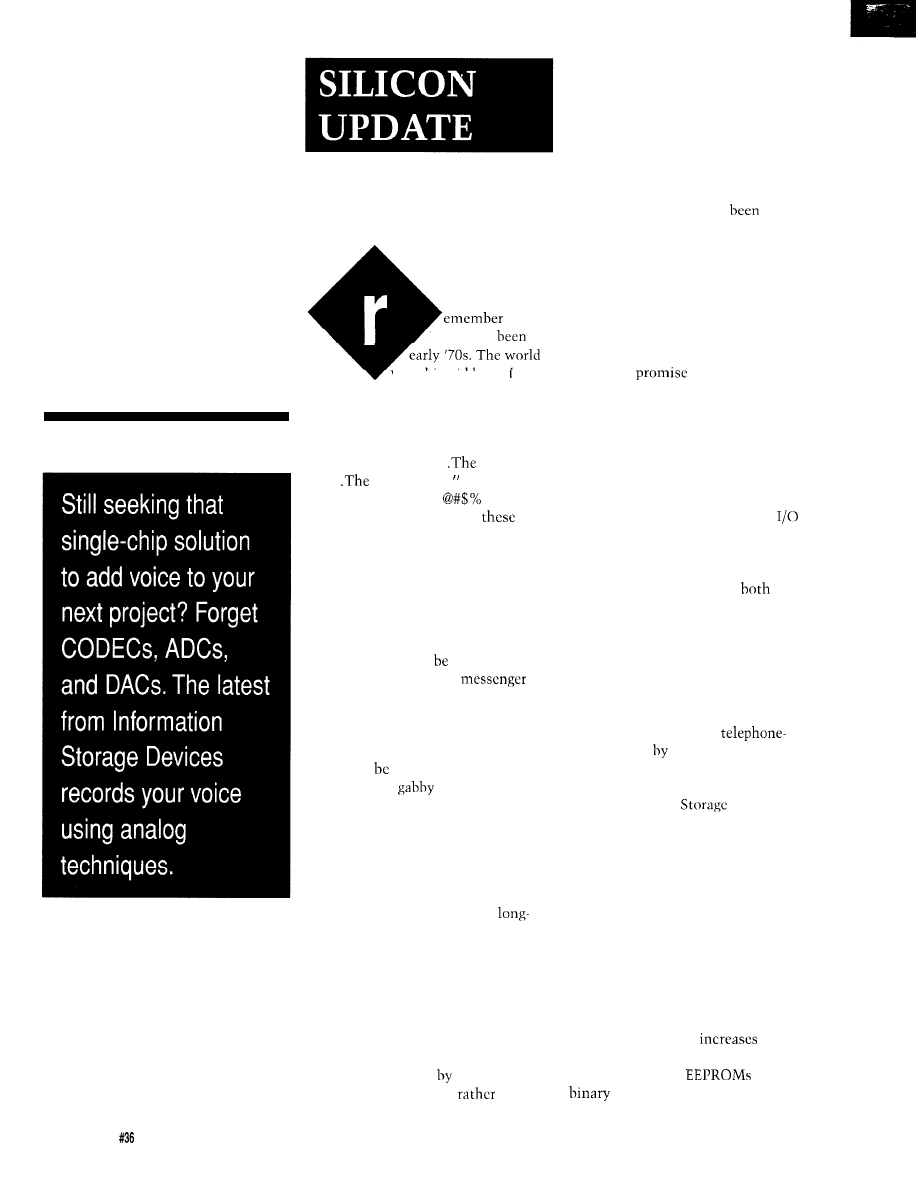
Talking
Chips
Tom Cantrell
when?
It must’ve
the
was chip-giddy, and
everything seemed possible. Then
some diabolical dashboard designers
decided that drivers would appreciate
nagging robotic mothers-in-law.
“The door is ajar..
door is
ajar..
door is ajar..
The door is not a
jar! If it
were, I wouldn’t be making
giant
car payments! And furthermore, it
would keep its mouth shut!
Thankfully, this “feature” has
long since disappeared.
However, it really isn’t fair to
criticize the whole concept of voice
output just because of one inappropri-
ate use. That would
the high-tech
equivalent of killing the
because you don’t like the message.
Indeed, if we observe the prime
directive that all sound-emitting
gadgets should have a volume control
(lest wires
cut as they were on
many of those
cars], then I can
think of a number of applications that
might benefit from vocalization.
Generally, they arc the applications in
which it is inconvenient, or even
dangerous, to rely on the operator to
read a visual display.
For instance, consider the
awaited air-collision avoidance
system. A visual indicator would
simply add yet another flashing light
and set of dials to the already over-
crowded instrument panel. While, in
contrast, a voice solution that directly
issued the command to “Pull
u p !
You’re about to crash,” would cer-
tainly be recognized
the pilot.
Which plane would you
fly on?
Another sensible application
would he a speaking hazardous-gas
detector. When crawling around
underground it can be rather inconve-
nient to have to keep looking up from
your task to check a visual display. Or,
in other cases, it just might he too dark
to see it. One definition of “sinking
feeling” might be, having
distracted for a minute or two, glanc-
ing at the visual display on the
detector only to see it says “RIP.”
On the more mundane front, there
are plenty of times when I’m trying to
probe a particularly messy rat’s nest of
cabling that I would like an audio
output on a VOM or oscilloscope.
If you
to design responsi-
bly (remember the prime directive), I’ll
fill you in on a unique technology that
allows you to add voice input and
output to your application with just a
handful of components.
YEAH, DAST THE TICKET
Traditionally, a digital voice
system uses an ADC to convert the
audio for storage in digital memory;
the recorded audio is then played back
via a DAC. Along the way,
input
and output sections need amplification
and filtering. The addition of a DSP, an
MPU, or a dedicated IC allows com-
pression of the digitized audio to a
degree depending on cost and quality
constraints. For instance, an ADPCM
(Adaptive Delta Pulse Code Modula-
tion) chip can compress
grade speech
a factor of two with
little loss of quality.
Now, thanks to DAST technology
from Information
Devices, it’s
possible to shrink the entire voice I/O
function into a single, easy-to-use,
low-cost chip.
DAST stands for “Direct Analog
Storage Technology” which, as the
name implies, dispenses with the A/D
and D/A converters by using a simple
method of directly reading (“playing
hack”) and writing (“recording”)
analog information. Cleverly, it does
so using standard EEPROM technol-
ogy. This makes the parts easy to
manufacture, which
yields
and in turn leads to lower cost.
Conventional
store
data by blasting a charge
62
Issue
July 1993
The Computer Applications Journal
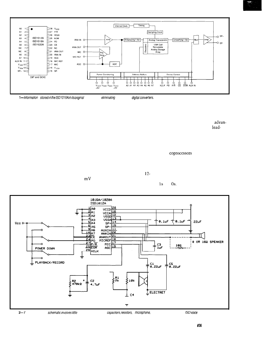
Figure
IS
analog form,
fhe need for
through a thin oxide layer onto a
cell voltage matches the sampled input
of DAST storage is nearly equivalent
floating gate. However, the DAST
as signaled by the voltage comparator.
to eight bits of digital storage.
concept exploits the fact that the
When the comparator voltage and the
Of course there are tradeoffs. If
floating gate can store intermediate
cell voltages match, the sampled data
there weren’t, with an 8: 1 cost
levels of charge, not just a 1 or 0.
is considered written into that cell.
tage, ISD would surely be the
The DAST write process works as
follows: An analog voltage is sampled
by the device. This analog voltage is
stored in a sample-and-hold capacitor
and is fed to one input of a voltage
comparator. Then, in a closed-loop
fashion, a series of small write pulses
incrementally increases the voltage on
the floating gate. The voltage level of
the gate is fed to the other input of the
voltage comparator. The incremental
writes continue until the EEPROM
A benefit of the DAST scheme is
that it is impervious to variations
between cells. Writing the same
voltage level to two unmatched cells
may require different numbers of write
pulses, but both will end up storing
the same voltage level because of the
comparator feedback loop.
each DAST cell can store 230 distinct
voltage levels. In other words, one cell
Across the range of O-2.75 V,
resolution is possible. This means
ing-if not the only-chip company in
the world. While such “multistate”
techniques (which incidentally have
and However, the technology is
long been used in such chips as 80x87
math
featuring a-level
microcode) are predicted to overcome
a good fit with the requirements of
future density limits of VLSI, for now
the extra write circuitry, variable write
time, and speed/accuracy tradeoffs rule
out DAST as a generic replacement for
Ucc
+
CHIP ENABLE
ucc
,
MIC REF
R3
+
_
MICROPHONE
I
22uF
Figure
he playback-only
more than a handful of
a
speaker, and of course the
chp
The Computer Applications Journal
Issue
July 1993
6 3
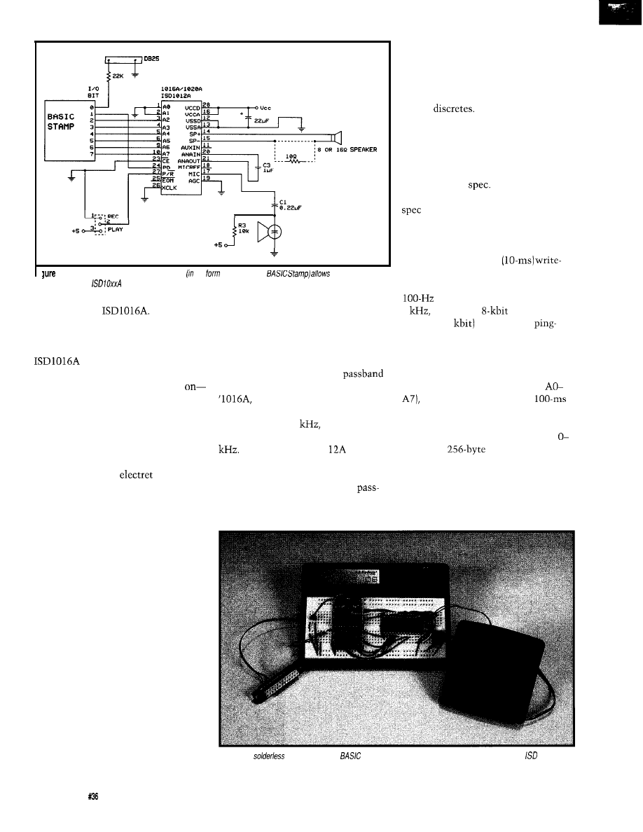
2
7
3-Adding some intelligence to the setup the
of the Parallax
you to record new
messages info the
chip.
low-cost voice I/O, a market directly
targeted by the
ELOQUENT SILICON
As shown in Figure 1, the
surrounds a 128K DAST
EEPROM array with all the messy
analog stuff-amps, filters, and so
in a single package. For this discus-
sion, I’ll break the functions down into
four basic areas-analog input, address,
control, and analog output.
On the input side, the MIC and
MIC REF signals are AC coupled to the
chip from a typical
micro-
phone (such as Radio Shack P/N 270-
090). Otherwise, only a biasing resistor
is required, although an extra RC
network to provide power supply
decoupling may be useful to help
reduce noise.
The output from the microphone
preamp then takes a detour off-chip
[ANA OUT). This pin is normally
connected back to ANA IN through a
capacitor and feeds the on-chip
amplifier. The capacitor simulta-
neously acts as a filter and as a
coupling capacitor. This admittedly
strange looking setup is intentional-it
allows you to substitute a direct
analog input for the microphone and
the extra capacitor serves as another
pole for the filter.
The input also features automatic
gain control (AGC) which handles
varying sound levels (i.e., whispers vs.
shouts) while maximizing dynamic
range and minimizing distortion. An
RC network connected to the AGC pin
determines the attack and hold
characteristics of the gain control.
The antialiasing filter is designed
to limit the input frequency to less
than the Nyquist limit. The
depends on the sampling clock. For the
which packs 16 seconds of
audio into the 128K DAST array, the
sampling rate is 8
so the cutoff
frequency for the filter is set at 3.4
ISD also offers a ‘10
which
features 12 seconds of storage. The
sampling clock for the ‘1012 is faster
than the ‘1016 and has a higher
band. The third chip in the ISD line up
is the ‘1020A. This chip offers a
sampling clock slower than the ‘10 16,
and it runs with a lower passband.
Speaking of the sampling clock,
it’s no easy feat to generate an accurate
clock without a crystal or any external
tuning
However, it is
important that the clock be rather
precise since variations of as little as a
few percent are easily detectable by
listeners. The on-chip clock generator
is trimmed at the factory for accuracy
within 1.5% of
The sampling
clock is also stable to within 0.5% of
over the operating temperature
and voltages for the device.
The “analog transceivers” block,
in Figure 1, hides some complexity
mandated by the slow
time of the EEPROM. Since the
EEPROM can only be written to at a
rate, and the sampling clock is
8
two sets of
input buffers
(80x100 = 8
are used in a
pong fashion as write buffers. While
samples are being written to EEPROM
from one buffer, the next sample is
accumulating in the other one.
For addressing purposes (via
samples are grouped into
fragments-which is the smallest
accessible unit of sound. Thus, the
‘1016A stores audio from addresses
159 in the
address space.
Addresses 192-255 (A6 and A7 high)
are reserved for programming various
“operational modes” that are most
appropriate for push-button (nondirect
addressing) applications.
Photo 1-A
breadboard and
Stamp processor board make experimenting with the
voice chips
easy.
64
Issue July 1993
The Computer Applications Journal
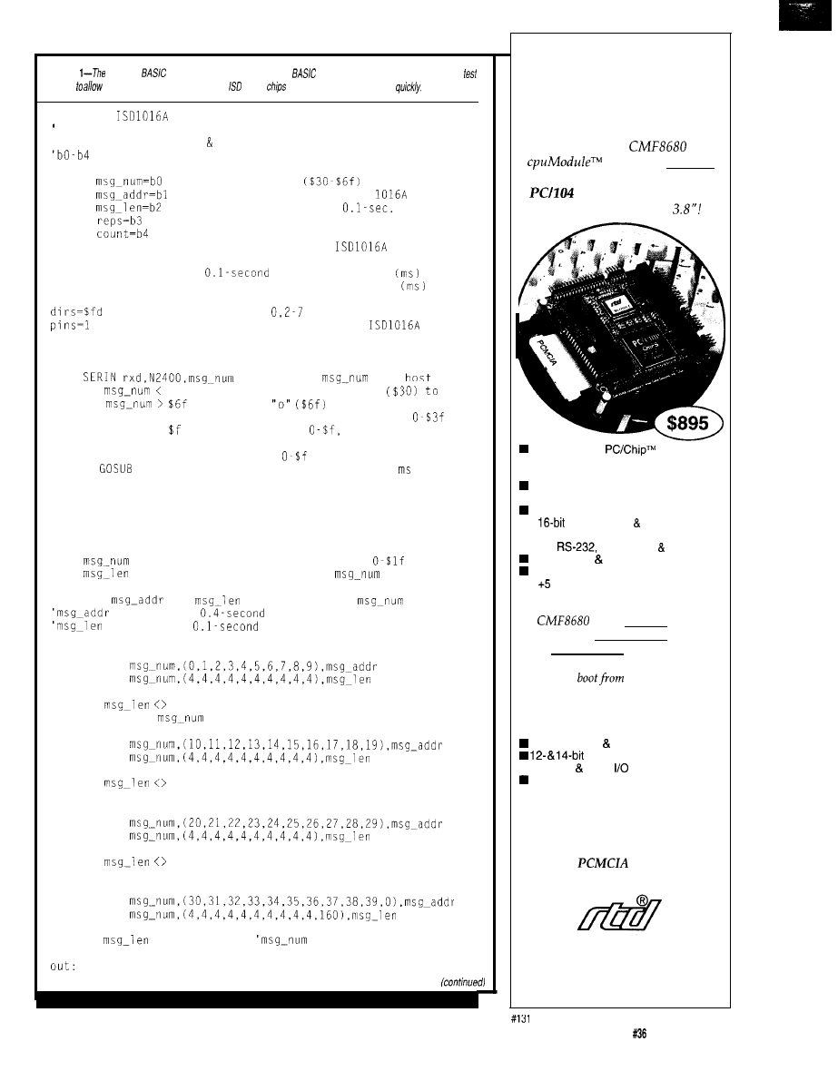
Listing
Parallax
Stamp includes a very useful
language on a very small board. A
setup
recording of messages on the voice
can be programmed very
'A simple
recorder
using the Parallax BASIC Stamp
'Define variables, pins constants.
are byte registers
symbol
message number
from host
symbol
address of message in ISD
symbol
length of message in
increments
symbol
repeat previous message reps times
symbol
message length loop counter
symbol pd=O
PIC pin 0 output to
PD
symbol rxd=l
PIC pin 1 serial input from host
symbol duration=100
message increment
symbol gap=250
gap between repeated messages
'make pins
output, 1 input
'PD high power down the
loop:
'wait for
from
IF
$30 THEN loop'valid range is "0"
IF
THEN loop'
msg-num = msg-num $30
'if valid then shift to
IF msg-num > THEN play 'if not
then play msg
FOR reps = 0 TO msg-num
'if
playrec
'then repeat previous
PAUSE gap
'1 to 16 times with gap
NEXT reps
'in between
GOT0 loop
'wait for next msg-num
play:
= msg-num $10
'shift msg-num to
= 0
'default if
not in table
'look up
and
corresponding to
specified in
increments
specified in
increments
'multiple LOOKUP statements are used so they fit on the screen
LOOKUP
LOOKUP
IF
0 THEN out
msg-num =
10
LOOKUP
LOOKUP
IF
0 THEN out
msg-num = msg-num 10
LOOKUP
LOOKUP
IF
0 THEN out
msg-num = msg-num 10
LOOKUP
LOOKUP
IF
= 0 THEN loop
was not in table-ignore
The New Shape
of
Embedded PCs
The amazing
is the first complete
100% PC-compatible
single
board computer
measuring only 3.6” by
16-bit, 14 MHz
n CGA/LCD controller
n 2M DRAM
ROM-DOS kernel
n bootable 1 M solid-state disk
configuration EEPROM
n
IDE controller floppy interface
n PCMCIA interface
n two
one RS-485 parallel port
XT keyboard speaker port
watchdog timer
n volts only operation
Designed for low power applications,
the
draws one watt of power,
which drops to 350 milliwatts in sleep
mode, 125 milliwatts in suspend mode.
Free utility software lets
your
application
ROM!
RTD also offers a complete line of
PC/l 04 peripherals for expansion:
1.8” hard drive PCMCIA carriers
data acquisition modules
n opto-22 digital
modules
VGA CRT/LCD interface
For more information:
call, write or fax us today!
Place your order now and receive a
CM102
carrier module
FREE!
Real Time Devices, Inc.
P.O.
Box
906
State
College,
PA 16804
(814) 234-8087
n Fax: (814) 234-5218
The Computer Applications Journal
Issue
July 1993
65
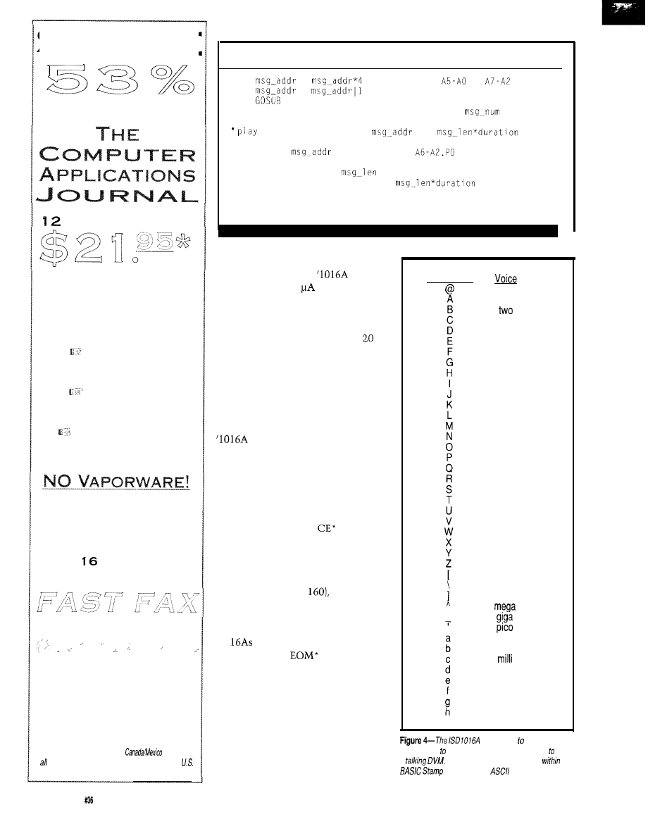
S
A V E
S
U B S C R I B E T O D A Y
T O
ISSUES FOR ONLY
W
R I T T E N
BYENGINEERS
FOR ENGINEERS!
H
A N D S
-
O N
H
A R D W A R E
P
R O J E C T S
A
D V A N C E D
A
P P L I C A T I O N S
T
E C H N O L O G Y
T
U T O R I A L S
To
TAKE ADVANTAGE OF
ALL THIS TECHNOLOGY,
JUST FILL OUT THE
SUBSCRIPTION CARD ON
PAGE
OF THIS ISSUE
AND
YOUR ORDER!
,
OR MAIL TO:
T
HE
C
O M P U T E R
A
P P L I C A T I O N S
J
O U R N A L
P.O. Box 7694
R
I V E R T O N
,
N J 0 8 0 7 7 - 8 7 9 4
‘Price
good in U.S. only.
$31.95,
other foreign $49.95. U.S. funds drawn on
banks on/y.
Listing
l-continued
=
'set bits
to
=
'set bit PD high
playrec
'play or record
GOT0 loop
'wait for next
or record message at
for
ms
playrec:
PINS =
'set
high
LOW pd
'power up
FOR count = 1 to
PAUSE duration 'wait for
ms
NEXT count
HIGH pd
'power down
RETURN
Control over the operation of this
chip is quite simple. When PD (Power
Down) is asserted, the
con-
sumes a miserly 1
(typical)-not
surprising since the EEPROM array
needs no power to retain its contents.
After deasserting PD, the chip starts
up and is ready for action within ms
or so.
ASCII Code
oh (zero)
Once powered up, whenever CE*
is asserted, the addresses are latched
and a playback or record cycle (depend-
ing on the state of the P/R’ pin)
commences. A recording continues
until CE* goes high at which point the
inserts an EOM (end of
message) marker in the data space. For
playback, a simple pulse on CE’ will
play the entire content of the ad-
dressed message until the EOM
marker is encountered. At this point
the EOM’ pin pulses low and playback
stops. Alternatively, if
is held
low, playback will continue through
the EOM markers. In either the
playback or record mode of the chip,
once the device reaches the end of
storage (i.e., address
the EOM’
pin will go low and stay there until a
PD cycle resets the chip. The latter
feature is useful for cascading multiple
‘10
using the “cascade operation
mode” in which
from the first
chip drives CE* from the next and so
on.
The only other control signal is
XCLK, which as its name implies,
offers the option of externally clocking
the chip. Before you get all excited
d n e
three
four
five
six
seven
eight
nine
ten
eleven
twelve
thirteen
fourteen
fifteen
sixteen
seventeen
eighteen
nineteen
twenty
thirty
forty
fifty
sixty
seventy
eighty
ninety
hundred
k
nano
micro
point
ohms
volts
amps
(play whole chip)
imagining strange uses, keep in mind
will hold up 16 seconds of
that it is mainly intended for test
audio, plenty sfore fhe 40 phrases necessary build
purposes or perhaps to generate a more
a
Each phrase is accessed from
fhe
program by an
character.
66
Issue July 1993
The Computer Applications Journal
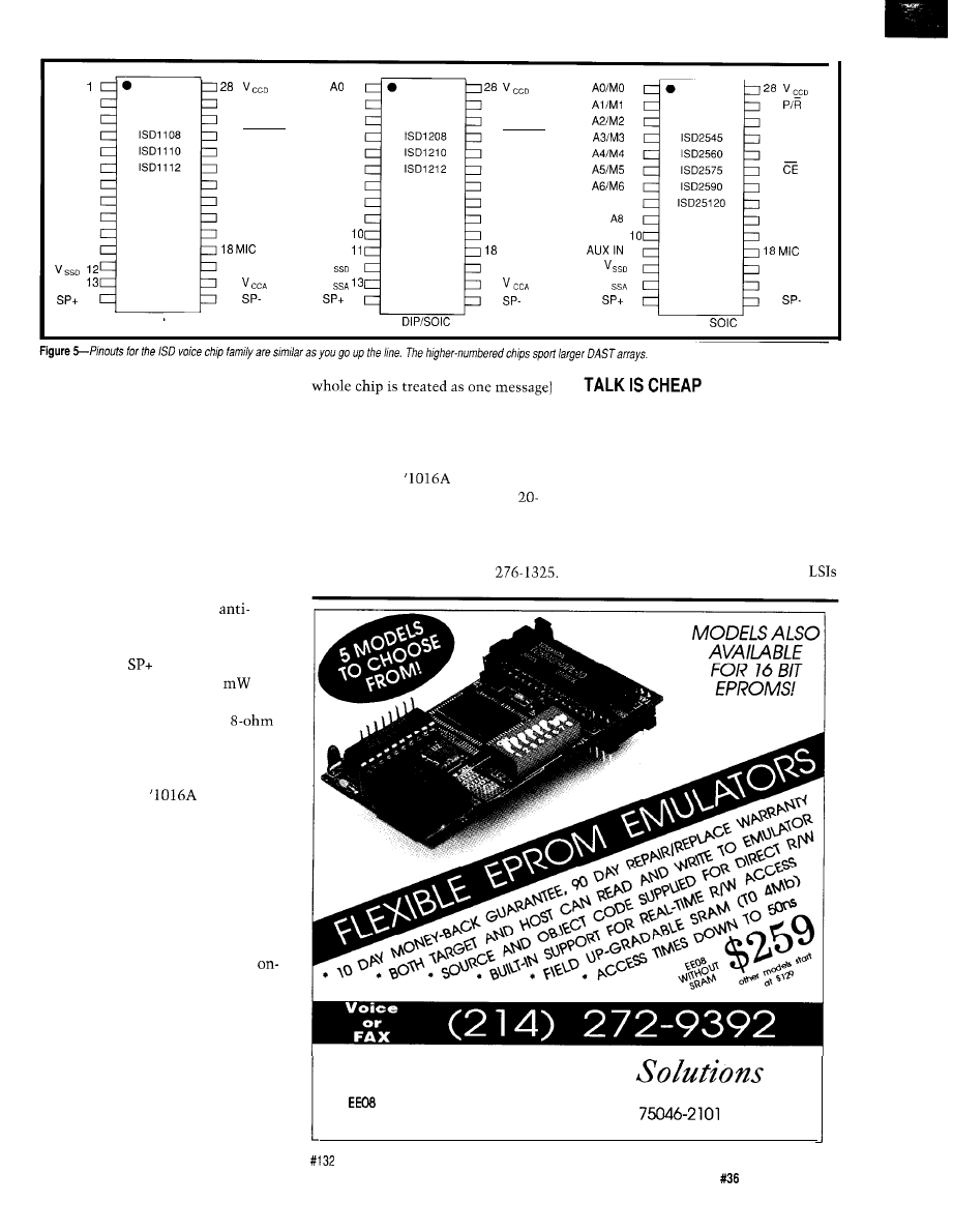
NC
N C 2
N C 3
NC 4
N C 5
N C 6
N C 7
NC
a
NC 9
NC
10
NC 11
VSSA
14
DIP
27
REC
26
NC
25
RECLED
24
PLAYE
23
PLAYL
22
NC
21 ANAOUT
20
ANA IN
19
AGC
R E F
17
MIC
‘ 6
15
1
Al
2
A2 3
A3 4
A4 5
A5 6
NC 7
NC
a
A6 9
A7
N C
V
‘ 2
V
14
27 REC
26 XCLK
25 RECLED
24 PLAYE
23 PLAYL
22 NC
21 ANAOUT
20 ANA IN
19 AGC
M I C R E F
17 MIC
‘ 6
15
1
2
27
3
26 XCLK
4
25 EOM
5
24 PD
6
23
7
22 OVF
A7
a
21 ANAOUT
9
20 ANA IN
A9
19 AGC
11
R E F
‘ 2
17 MIC
V
‘3
‘6 V
C C A
14
15
DIP
and
playback and record setup. Believe me,
putting audio in an application doesn’t
get much simpler than this.
It also doesn’t get any less expen-
sive since the
is only $6.64
(1000s). Keep an eye out for the
second variant (‘1020A) at your local
Radio Shack. Their version is the
ISD 1000 priced at $17.99 each, where
it is stocked as part number
Feeling the urge to wire something
up, I decided to design a simple
subsystem that would accept a
“message number” via an RS-232 link
and then play or record that message.
The design combines the ‘1016A with
the new Parallax PIC-based BASIC
Stamp computer (Figure 3 shows the
schematic and Photo 1 shows the
project). Other than these two key
precise clock. The range of clock rates
supported is not that wide since it is
bounded on the low end by droop in
the sampled analog inputs and on the
high end by EEPROM write time.
Since you probably won’t be using it,
remember to ground it lest you find, as
I did, that leaving it open results in
erratic operation (or better put, a bad
case of chip laryngitis).
For playback, the analog output is
fed through an internal smoothing
filter (which is actually the
aliasing filter during record mode
serving double duty) and amplifier for
output at the
and SP- pins. The
amplifier output is about 50
and
can directly drive a 16-ohm speaker.
You can use an easier-to-find
speaker simply by inserting an appro-
priate resistor (e.g., 8-10 ohms) in
series with the SP- pin.
Experienced
users report
that it is important to use a boxed
speaker, not just one hanging in the
breeze, for best sound quality. Such a
setup is loud enough to hear across the
room, but further amplification will be
required for high-ambient noise levels
or for public address applications. As a
convenience, an AUX IN pin is
provided to take advantage of the
chip amplifier when it isn’t being used
for playback. Whatever signal is seen
at the AUX IN pin is passed through to
the speaker outputs when the chip is
not playing back a message.
Putting a system together involves
little more than a handful of parts.
Figure 2 shows the schematic of a
minimal, nonaddressing (i.e., the
CALL OR FAX
TODAY FOR MORE
Technical
INFORMATION ON
ME
AND OUR
COMPLETE LINE OF
EPROM EMULATORS!
PO BOX 462101
GARLAND, TX
The Computer Applications Journal
Issue
July 1993
6 7
and an off-the-shelf
speaker, the
additional component count was just a
PLAY/RECORD jumper, and a few
However, I did have to make some
compromises since the Stamp only
resistors and capacitors.
offers eight I/O lines when a complete
interface would call for thirteen
(twelve for the
and one for the
RS-232) lines.
Given that the RS-232 line and the
CE’ line of the ‘1016 were required,
and needing to trim five lines from the
I/O budget, I quickly decided that the
least-significant address bits could go
since 0.1 -second message address
resolution was overkill for me. By
grounding
and Al, I settled on
second minimum address resolution.
This decision trimmed two lines from
the requirement. The next decision
was to ignore EOM* by handling
message length in software-three
down, and two to go. Okay, I can gain
one more line if I use a jumper, or a
switch, for selecting the play/record
mode. Four down, one to go. But, I did
want to use PD to minimize power,
allowing the whole gizmo to run off of
the Stamp’s battery and regulator, so I
Mildly discouraged, I stared at the
had to keep that one. Yes, as usual, I
ISD data sheet, and by reading the
application note again
I
found a
ended up one line short.
solution. It turns out that CE* really
isn’t required. Instead, it can be
grounded and PD alone used to initiate
record and playback cycles. Great!
Now I have enough lines on the Stamp
to make this idea possible!
The Stamp program (Listing 1)
accepts a byte from the host and
interprets it as a message number
which is played or recorded according
to the state of the
P/R* pin.
Using the SERIN command, the Stamp
waits for a message number from the
host and decodes it as a new message
or repeat count
= 1
to 16 repeats). Using the novel
LOOKUP instruction, the message
number is translated to a message
address (in 0.4-s increments) and a
length (0. l-s increments) and the
command is issued to the
for
the appropriate length of time. Since
EOM’ isn’t used in this design, the
only difference between playback and
recording is the state of the P/R* pin.
The number and length of mes-
sages is defined by the LOOKUP table.
In this example, I went the talking
DVM route and recorded forty
second messages listed in Figure 4.
Sending, for example, the string
will speak the phrase
“two hundred forty-eight point oh
seven
amps.” Notice how the
last message code, the “h” command,
plays the whole chip back, which
makes it sound like that guy in
commercials that talks really fast. You
could relax the pace using the
second chip (‘1020A) and stretch each
message length to 0.5 seconds by
changing the “duration” constant in
the program from 100 to 125.
Notice the shortcuts I took with
the microphone input (compare Figure
2 with Figure 3) such as grounding the
AGC pin thus fixing the preamp
output at maximum gain. I experi-
mented with the AGC, but found it
ECAL Universal
Product Information
ECAL is
complete
assembly-language development system that provides all the tools needed to assemble, link,
load. run. and debue
for
170
Bv
user-editable control files. the ECAL
Assembly Language
in
its full configuration can
with unsurpassed speed
and consistency.
Using the familiar DOS-based text windows. you can edit, assemble, set breakpoints. trace execution,
watch registers and
and communicate with
target’s serial port in separate closable windows. If you
prefer
other tools, with a few keystrokes,
incorporate your previous work into its consistent
andintuitiveenvironment.
The free ECAL evaluation program features all of the ECAL tools for all of the
Ordering Information
supported micros, giving you a true sampling of ECAL development cycle (source and
Alternative to Real-Time Emulator
ECAL OAS
object length limited).
Support for 805
and 186
ECAL with EPROM Emulator
withadditional
ECAL Single Processor
hardware and software to satisfy your need for economical project development tools.
Support
for 170t additional processors
control of syntax and
Extremely fast assembly-2
Integrated split-screen editor or command-line
assembly supported
Integrated linker/loader
Instruction trace and I/O windows
Monitor and RS-232 corn. windows
Single micro processor versions available
Optional EPROM emulator and programmer
Source-level debugger
Contact
Vail Silicon Tools
vail
692-A S. Military Trail
Deerfield Beach. FL 33442
Tel: (305)
Fax: (305) 428-1811
Silicon Tools
68
Issue
July
1993
The Computer Applications Journal
disconcerting for short messages
(messages in the
range)
since the gain didn’t have time to
stabilize. The only component that
seemed to have a dramatic effect on
recording quality was the
frequency bypass capacitor.
Even with my simplified design,
I’d say the results I achieved back up
ISD claims of “telephone grade” audio.
Messages were loud and clear but there
was a slight hiss (both likely due to
grounding AGC). Since the volume
was surprisingly high, I implemented a
home-brew “low-pass filter” by
sticking the speaker in a cardboard
box. The result was much mellower,
but still quite clear.
Remember, mainly “playback”
applications (i.e., factory vs. field
programmed ones) can achieve higher
quality by recording and editing with
audio gear (including a
equipped PC) and using the ANA IN
pin for programming. For best results,
consider the official ISD evaluation
unit/programmer-the
which
sells for a reasonable $299.
THE LONG AND SHORT OF IT
ISD expects to fill out the lineup
shortly with both shorter and longer
duration parts. For
information
on these parts, see Figure 5.
So, don’t hesitate to take advan-
tage of these unique talking chips;
just make sure they mind their
manners.
q
But for those of you who want to
Tom Cantrell has been an engineer in
play with parts right now, you may
Silicon Valley for more than ten years
want to play with what’s already
working on chip, board, and systems
shipping. The 64K
design and marketing. He can be
series offers
capacity
reached at (510) 657-0264 or by fax at
sampling rate) at only $5.78
(510) 657-5441.
(1000s).
The major difference between
the 1100 and 1200 is the latter sup-
ports direct addressing while the
former doesn’t.
Expected shortly are members of
the ISD2500 family. These devices will
feature a 480K DAST array-nearly
four times the capacity of the
These chips will be priced to go
and will store from 45
seconds to 2 minutes of audio
ing on the sampling rate [e.g., 60
Information Storage Devices, Inc.
2841 Junction Ave.
San Jose, CA 95134
Parallax, Inc.
6359 Auburn Blvd., Suite C
Citrus Heights, CA 95621
(916)
Fax: (916) 721-1905
BBS: (916) 721-9607
with the addition of two more
address lines and an
pin that
facilitates cascading.
416 Very Useful
417
Moderately Useful
418 Not Useful
MOVE OVER INTEL
MICROMINT SOURCES
CMOS BASIC CHIP
Micromint has a more efficient software-compatible
successor to the power-hungry Intel
chip. The
chip was designed for indus-
trial use and operates beyond the limits of standard
commercial-grade chips. Micromint’s
chip is guaranteed to operate flawlessly at DC to
12 MHz over the entire industrial temperature range
(-40°C to
Available in 40-pin DIP or PLCC
chip
OEM IOO-Qty. Price
BASIC-52 Prog. manual
$25.00
$14.50
$15.00
MICROMINT, INC.
4
PARK ST., VERNON, CT 06066
TO ORDER CALL
The Computer Applications Journal
Issue July
1993
6 9

The Art of
Battery
Management
John Dybowski
to embed all the
it’s time to consider your options for
power supplies. Hopefully, if you
decide to embed the power source as
well, you will pause and give serious
consideration to some of the outlying
functions associated with this deci-
sion. Sometimes you can get away
with just a rechargeable battery, a
diode, and a resistor. Often you will
need more functionality than this
simplistic approach can provide. Each
battery system can be as unique as
the product it is supposed to power,
and the choice of a battery system
often has implications beyond just
providing a source of power to your
product.
Too many battery-powered
instruments rely on extremely primi-
tive forms of battery management:
You know the battery needs charging
when the device stops operating; you
know you have to replace the battery
when it can’t hold a charge anymore.
How’s that for a system that promotes
happy users?
As an example, consider the case
of the weekend camcorder-jockey.
Following the usual charging interval,
he snaps the battery pack into the
camera. The battery indicator shows
all systems are go. The awareness that
this indicator means next to nothing
may eventually surface, because after
ten minutes the low-battery light
comes on. Obviously there’s some-
thing wrong here. If this person is
lucky enough to know someone who is
familiar with electronics, he probably
could persuade them to look at the
offending battery. With some luck (and
several discharges followed by slugs of
charging current) the battery may
come back to life-then again, maybe
not.
This intolerable state of affairs is
very inconvenient at best and as a rule
usually happens at the worst possible
time. Most people feel that given the
cost of modern consumer gadgets, they
should be designed properly to begin
with. “Properly designed” means
different things to different people but
even the most undemanding want to
know when the battery is on its way
out.
Now, the battle for the decent
battery supply has usually been fought
incrementally and has commonly been
conducted based on product
and product differentiation. For
example, designer A decides to use a
battery to power his product. Designer
B did one better and uses a recharge-
able battery, only he was a cheapskate
and used a diode and a resistor for the
charger. Designer A notices designer
B’s shortcoming and came back with a
better constant-current charger.
Designer B has a bright idea and
strikes back with a two-stage fast
charger and provides three
that
presumably show the amount of
battery capacity that is available.
Designer C was watching designer A
and designer B and decides to enter the
game. His solution to everything is
putting bigger cells in his aftermarket
battery on the assumption that bigger
is better.
To an extent, this progression is a
case study in the natural evolution of
products and cannot be considered
unreasonable. But your perspective
still boils down to where you draw the
line on what can be called a good
product. This is especially true in the
very vital power source because
shortcomings in the supply are
immediately perceptible. The heat is
on to provide better battery supply
systems since electronics have evolved
to such a degree of miniaturization
that the battery is usually the bulkiest
and heaviest component in the system.
The customers have their expectations
when it comes to battery-operated gear
and they are merciless. Rightly so,
70
Issue July 1993
The Computer Applications Journal
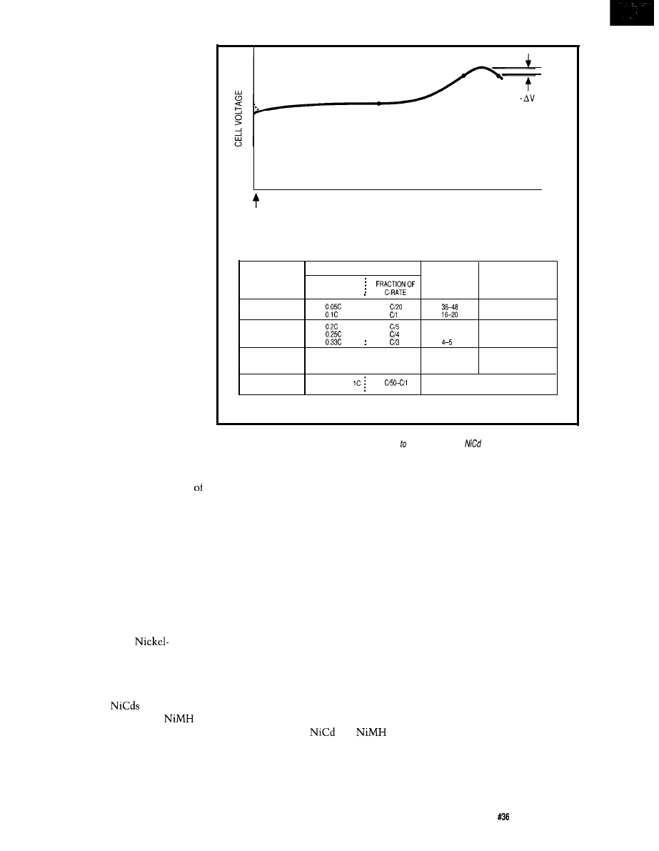
since they know their needs and they
expect you to know them too!
It’s not adequate to keep increas-
ing the battery size just because more
capacity is needed. There’s no place in
today’s market for battery status
indicators that tell you the battery just
went flat. A brute force mentality and
slipshod design practices seem to be
finally dropping out of vogue.
The design of electronic systems
that consider battery operation
alleviates this problem somewhat. The
rules for designing for low power are as
follows: apply low-voltage CMOS
circuitry, use selective power control
to various electrical subsystems, and
place more emphasis on thoughtfully
designed power supplies.
Attention is now being focused on
the battery side of the equation also.
These changes involve the develop-
ment of new battery chemistries, the
improvement of older ones, compre-
hensive battery charging and condi-
tioning regimes, and the accurate
gauging of the actual usable battery
capacity.
Combining intelligence in the
battery management strategy and a
sound power management approach in
the electronics along with one of the
newer battery technologies, such as
Nickel-Metal Hydride, can yield truly
impressive results. The consequence
such an approach is evidenced by the
level of performance attained by
notebook computers and pocket
cellular phones. I’ll be covering battery
management and conditioning tech-
niques in due time. However, it’s
unavoidable to recap some battery
basics before I do so.
COMMON CHEMISTRY
Amp hours (or milliamp hours) is
the unit of measure used to describe
the battery’s storage capacity. The C
rate is defined as the rate of amps (or
milliamps) equal to the capacity rating
of the battery. The use of this capacity
yardstick (along with its multiples and
fractions) serves to expedite the
discussion of different types of batter-
ies and a range of battery sizes.
Three popular battery technolo-
This battery storage capacity is
gies in common use are
dependent on the discharge rate. When
Cadmium, Nickel-Metal Hydride, and
the energy is withdrawn from the
Lead Acid. Each has its specific uses
battery at a faster rate, there will be
based on size, energy density, and,
less effective capacity. That is, the
perhaps most importantly, cost. I’m
usable capacity is time dependent and
sure most users of
would be
because of this, a known discharge rate
more than happy to step up to
must be implied to properly describe
batteries, but often cost is a deterrent
battery performance.
and
to their doing so. Rechargeable
cell capacity is usually specified at a
batteries are differentiated by several
five-hour discharge rate. Because of
key parameters such as storage
this consistency, published capacities
capacity, nominal voltage, cutoff
for these types of cells generally
CHARGE INPUT
FULLY
DISCHARGED
METHOD OF
CHARGE RATE
CHARGING
MULTIPLES OF
RECHARGE
CHARGE
C-RATE
TIME’ (HOURS)
CONTROL
STANDARD
0
NOT REQUIRED
7-9
QUICK
5-7
NOT REQUIRED
C
C
1.2
FAST
2c
2c
0.6
4c
4c
0.3
REQUIRED
TRICKLE
0.024
0
Used for maintaining charge of a
fully charged battery
‘RECHARGE TIME = STANDARD TIME TO FULLY CHARGE A COMPLETELY DISCHARGED BATTERY AT 23” C
Figure l--The
classic Nickel-Cadmium fast-charge profile (top) shows a characteristic bump and slight drop in
voltage when fhe cell is fully charged. This V may be used sense full charge.
cells are typical/y charged
using one of four methods (bottom), each of which has its uses.
voltage,
and maximum tolerated rate
of charge.
correlate among the different manufac-
turers. Since the five-hour rate is
almost universally used, it is seldom
given in the battery specifications. The
same is not true of lead acid batteries.
Due to the dissimilar applications for
lead acid batteries, the capacity ratings
are given for different rates of dis-
charge.
Generally, lead acid batteries can
be categorized into three broad
divisions according to their usage:
standby, cyclic, and motor starting.
Batteries used in standby service are
usually held on a trickle charge for
long periods of time and may be called
upon to deliver power for periods
ranging from several hours to several
days. Examples of this type of service
would be backup power for emergency
lighting systems or electronic equip-
ment. Batteries in cyclic operation can
supply power for several hours before
charging is required. Cyclic operation
would be characterized by cordless
The Computer Applications Journal
Issue July 1993
71
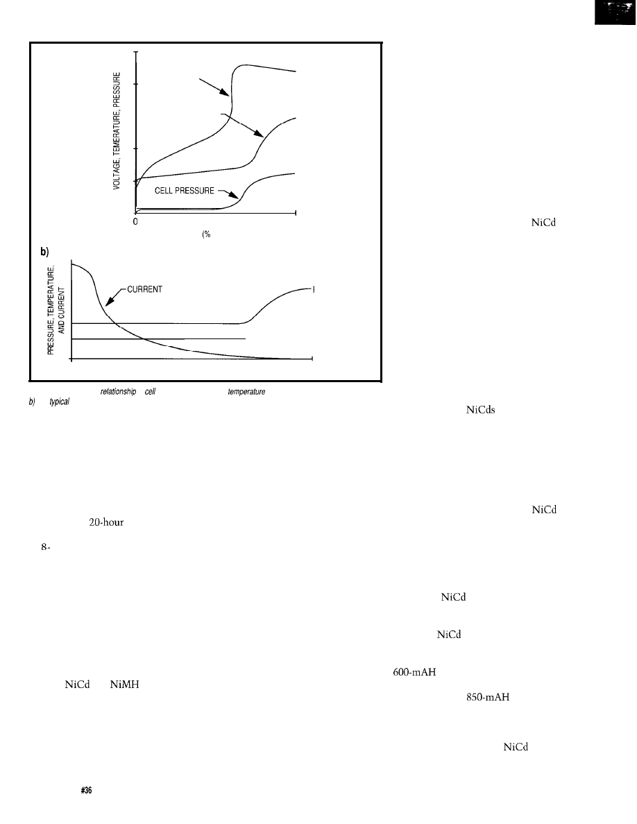
a)
CELL VOLTAGE
__ CELL TEMPERATURE
50
100
150
CHARGE RETURNED OF PREVIOUS DISCHARGE)
PRESSURE
- T E M P E R A T U R E
TIME
Figure 2-a) The
typical
of
voltage, pressure, and
during constant-current charging.
The
relationship of cell current, pressure, and temperature during constant-voltage charging.
power tools. Motor starting applica-
tions require high peak currents that
may discharge the battery over a
period of a few seconds.
Because of these different uses,
lead acid batteries are rated based on
their expected application. Batteries
intended for standby usage are gener-
ally rated at a
discharge rate.
Cyclic batteries are usually specified at
an or IO-hour rate. The nature of
motor start and other short duration
high discharge applications dictates
that the l-hour rate be applied for
these. In all these cases, the discharge
rates are clearly stated in the battery
specifications.
Nominal voltage is another
important restriction which deter-
mines how many cells are required to
achieve the total desired battery
voltage.
and
cells nomi-
nally supply 1.2 volts whereas a lead
acid cell produces 2 volts.
The terminal voltage decreases as
charge is withdrawn from a battery.
The cutoff voltage is the minimum
voltage the battery can be taken down
to before cell damage occurs. This
voltage varies among the various
battery compositions. It’s important to
note that the cutoff voltage determines
the amount of energy that can be
drawn from the battery. Should you
have a situation where the device that
is operating from the battery cannot
function down to the cutoff voltage, all
of the battery’s useful energy will not
be depleted. To determine the amount
of energy that can be drawn from the
battery in such applications, you must
consult the discharge curves that plot
terminal voltage versus discharge rate
versus time.
Charging is accomplished by
applying a current of proper polarity to
the battery. This can be a pure DC
current or can contain a significant
ripple component. This ripple gener-
ally results from the use of a rudimen-
tary half-wave or full-wave rectifier
which represents the baseline of
battery charger schemes. The situation
can (and should) get more complex.
Constant voltage or constant
current charging illustrate two
variations that are frequently applied
to deliver energy faster to batteries.
With higher charge rates, a variety of
feedback techniques can be used to
determine the point at which the
charging current is to be reduced.
Many forms of temperature sensing,
voltage sensing, or current sensing (or
combinations of any and all of these)
are used in this regard. This reduction
in charging current becomes necessary
to prevent damage to the battery and is
not only dependent on the battery
chemistry but on the specified charg-
ing capabilities of the batteries.
batteries, for example, can be obtained
with capabilities that can be defined as
Standard Charge, Quick Charge, or
Fast Charge.
Overcharge is the continued
charging of a battery after the battery
has reached its maximum state of
charge. Batteries are designed to
handle continuous overcharge at their
cell specification rate. This rate is the
determining factor that indicates when
charge control is required to drop the
charging current down to a lower rate.
The Standard Charge, Quick Charge,
and Fast Charge
that I men-
tioned not only have different restric-
tions on their maximum charge rates
but also on the amount of continuous
overcharge they can handle.
NICKEL CADMIUM BATTERIES
Perhaps the most widely used
rechargeable battery chemistry,
batteries have become the established
battery system for many applications.
Possessing excellent high-drain
discharge capabilities and cycle life
characteristics of 500 to 1000 cycles
along with decent self-discharge
properties,
batteries are used for
everything from cordless power tools
to memory backup applications.
Although
batteries use a fairly
stable technology, performance
improvements continue to be made. A
capacity from an AA cell
was typical a couple of years ago and
now you can get
capacity at
a reasonable cost and from the same
size battery.
Several different charging schemes
are commonly applied to
batteries. Naturally, the method used
72
Issue July 1993
The Computer Applications Journal
determines the complexity of the
charging circuit; constant-current
methods are generally preferred.
Furthermore, different types of
batteries are produced that are specifi-
cally designed to tolerate higher
charging rates or that have the capabil-
ity of operating at higher temperatures.
Some of these allow simple charging
circuits whereas others require some
form of charge control that will fall
back to a lower rate of charge once a
full charge is attained.
Detection of a full charge condi-
tion is often based on the ramp in
heating that occurs at the end of
charge cycle. This condition can be
sensed by directly monitoring the
battery temperature using a sensor
housed in the battery. This method is
not without problems since the
temperature sensor will usually
contact only one or two cells, leaving
the remainder out of the picture.
A popular derivative of tempera-
ture sensing is the negative delta
voltage method. This voltage phenom-
enon occurs at the end of charge cycle
following a steady increase in voltage
when a battery’s temperature increase
causes a decrease in internal resistance
that, in turn, results in a drop in
voltage. Since all the cells have a say
in the charge termination decision,
this proves to be a reliable indication
of the overall state of charge of the
battery. Figure
1
illustrates this
voltage profile and also contains some
pertinent figures on the various charge
rates that are commonly used for the
different
battery types.
When a
battery is charged, a
small amount of energy goes into
converting active materials into an
unusable form. Charge acceptance is
the term used in describing the general
charging effectiveness. This defines
the charging efficiency and the amount
of discharge capacity that can be put
into the battery.
batteries accept deliverable
charge at different rates depending
upon factors such as the state of charge
of the battery, charge rate, and tem-
perature. Battery history, which refers
to the type of usage the battery has
been subjected to, also figures in the
charge acceptance criteria.
NEW 8031 FAMILY PRODUCTS from RIGEL
FUZZY-LOGIC CONTROL CODE GENERATOR
FLASH (Fuzzy-Logic Applications Software Helper) generates
MCS-51 language
subroutines to perform fuzzy-logic control tasks from a high-level description of
fuzzy rules written with linguistic variables. An extensive tutorial and illustrative
examples
are
provided. ($100.)
R-5355 READS TRAINER
READS (Rigel’s Embedded
Applications Development System) and
the R-535J board constitute a complete
hardware/software development and
debugging system in one user-friendly
menu-driven environment which runs
on an IBM PC host. Programs in the
MCS-51 language may be written,
edited, assembled, downloaded and
debugged without leaving the
integrated environment. The R-535J
board uses the powerful
microcontroller. R-535J READS with
User’s Guide on disk and example
programs is priced at $150, $130 as a kit.
8031 FAMILY MICROCONTROLLERS EXPERIMENTER’S GUIDE
This
page textbook covers the MCS-51 assembly language, using the on-chip
facilities of the 8031 family microcontrollers, and software hardware experiments.
Programming nuggets are given for each instruction and each operating mode of
the family. Features of the
are highlighted. ($30.)
CORPORATION
PO BOX 90040, GAINESVILLE FL, 32607
The Computer Applications Journal
Issue
July 1993
73
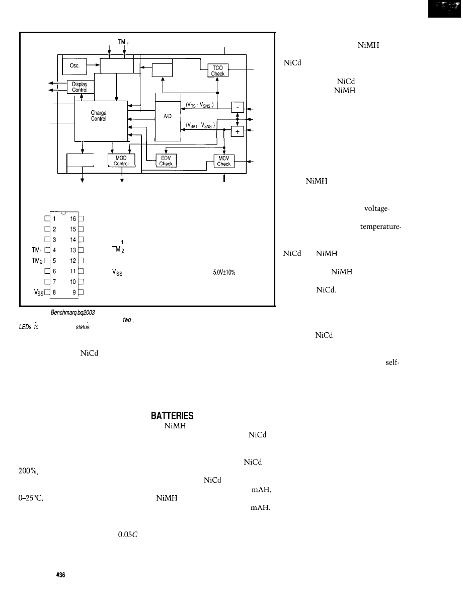
TEMP
CHG
CCMD
DCMD
DVEN
T M ,
Vcc
Timing
Control
LTF
Check
.
State
Machine
Discharge
Control
TCO
TS
SNS
BAT
MCV
DIS
MOD
Vss
Pin Connections
Pin Names
CCMD
DCMD
DVEN
TS
BAT
V c c
DIS
MOD
CHG
TEMP
MCV
TCO
SNS
CCMD Charge command/select
DCMD Discharge command
DVEN V enable/disable
TM
Timer mode select 1
Timer mode select 2
TS
Temperature sense
BAT Battery voltage
System ground
SNS
Sense resistor input
TCO Temperature cutoff
MCV Maximum voltage
TEMP Temperature status output
CHG
Charging status output
MOD
Charge current control
DIS Discharge control
V c c
power
Figure 3-The
can be used to monitor and control the charging of numerous kinds of
rechargeable batteries. The chip handles one-,
and three-stage charging and has outputs that directly drives
show the current
Both the charge efficiency and the
actual capacity of a
battery are
reduced when charged at high tem-
peratures compared with those charged
at room temperature. A couple of
examples will help to put this in
concrete terms, with a cell tempera-
ture of 45°C and a charge input of
200% of nominal capacity, no more
than 70% of nominal capacity will be
attained. Capacity levels become
adversely affected with increasing
temperatures. With a battery tempera-
ture of 60°C and a charge input of
the actual battery capacity will
be no more than 45%. Charging the
same battery at temperatures ranging
the charge acceptance is much
better, and a charge input of 160%
would yield 100% capacity.
enhanced by rates higher than 0.1 C for
battery types that can accept charging
at higher rates. Using a fast-charge
battery, charging it at 1 C approaches
100% of nominal capacity at an input
of 120%.
NICKEL METAL HYDRIDE
Charge rates also influence charge
acceptance. Charge rates below
will not allow the battery to ever
achieve its full capability. Efficiency is
batteries offer a significant
When considering which charge
increase in power density over
method to use for this kind of battery,
batteries. This increase comes at a
you must give attention to the time
significant cost, however, since these
available for charging, the temperature
are about twice the price of a
extremes the battery will operate
battery of the same size. Looking again
under, the number of cells required,
at a modern AA
battery which is
and the way the battery will be used.
available with a capacity of 850
As with the other battery chemistries,
a
battery of the same size
there are alternate methods that can be
typically has a capacity of
1200
selected for charging lead acid batter-
These batteries are finding uses in
ies. Constant-voltage charging is often
applications where longer run time is a
used and is usually considered the
key competitive feature and where the
conventional charging method for
battery price represents a relatively
charging lead acid batteries. Constant
small portion of the product cost.
current, taper current, and other
Although there are some important
differences to consider,
batter-
ies perform in a similar manner to
batteries.
Generally, the same charge
method used for
batteries can
also be used for
batteries,
although certain control limits may
have to be changed to ensure proper
operation of two-stage chargers. The
most notable difference between the
charging characteristics of these two
batteries is the lack of a pronounced
decline in cell voltage (negative delta
voltage) at peak charge. If you decide
to use a voltage-sensing system to
charge
batteries, you would be
wise to carefully evaluate the perti-
nent circuit parameters. It might not
be a bad idea to dismiss a
monitoring approach completely and
instead consider using a
profile cutoff method instead.
Service life is also similar between
and
batteries, although
self-discharge is presently still slightly
higher and the
battery is not
quite up to the high discharge capabili-
ties of the
LEAD ACID BATTERIES
Lead acid batteries find uses in
many of the same application areas
served by
batteries. Starved
electrolyte sealed lead batteries are one
of the more advanced forms of lead
batteries in use today. With low
discharge characteristics and a
lifecycle approaching ten years under
float conditions, this battery chemistry
has obviously continued to evolve
along with the other technologies that
I’ve already described.
7 4
Issue
July 1993
The Computer Applications Journal
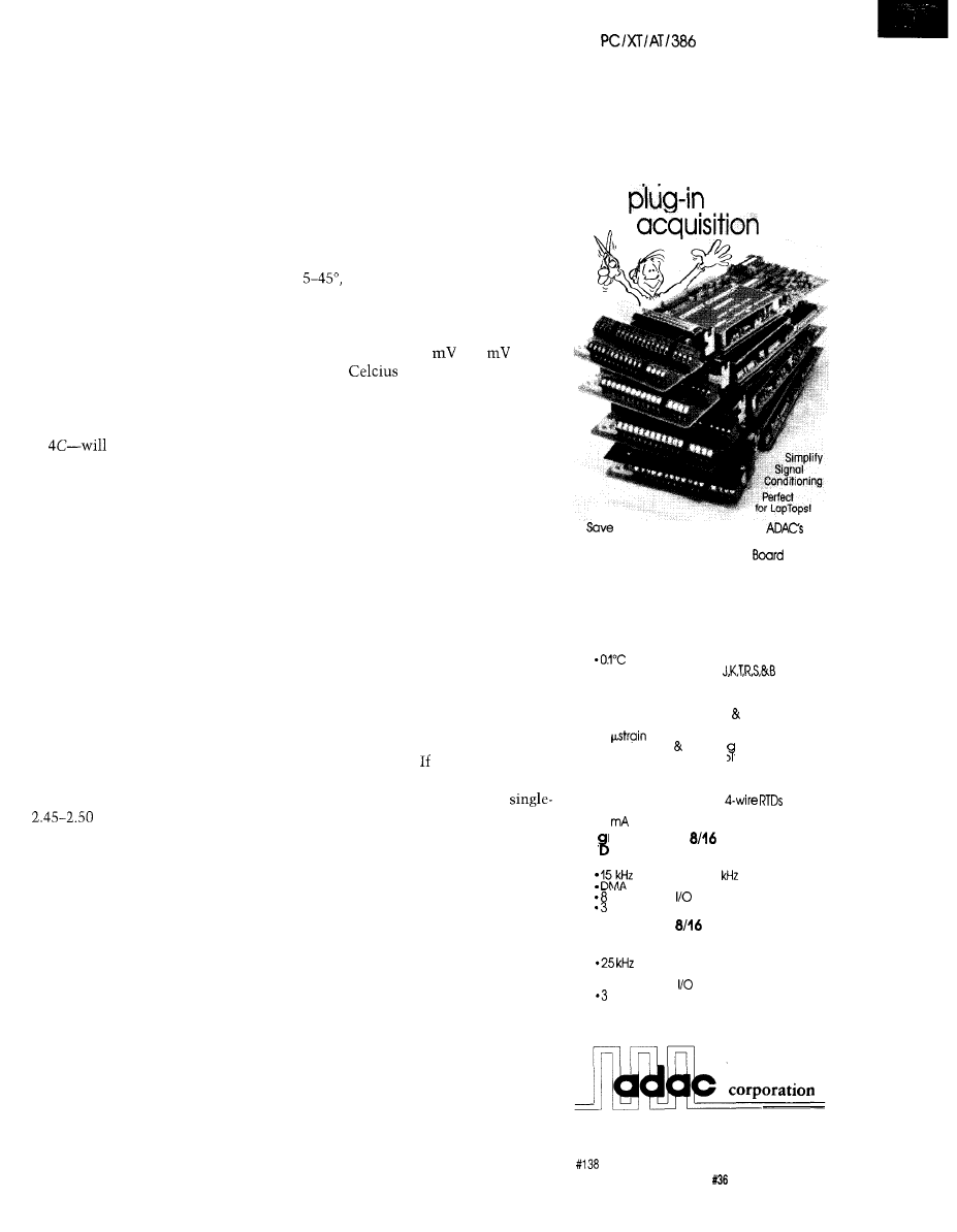
Users!
variations may also be used with good
results.
Using constant-voltage charging,
the charger holds a uniform voltage
regardless of the battery’s state of
charge. Here, the charging current
varies depending on the difference of
potential between the input voltage
and the battery voltage, thus the
battery will draw greater current when
it is at a discharged state. As charging
continues, the battery voltage rises and
the charge current diminishes. Current
limiting is not required for many types
of lead acid batteries using this
charging method. Constant voltage
charging can be used for fast charging
as well as in float charge applications.
Since lead acid batteries have low
internal resistance, high currents-up
to
flow into a discharged
battery if the current is not limited by
the charger’s current supply.
As a result of the large current
flow involved, up to 70% of the
previous charge may be returned in the
first 30 minutes of charging. In this
case, though, as the battery voltage
increases quickly, the resulting
reduction in potential difference
causes the current to drop off signifi-
cantly. As a result, although the
battery regains a significant portion of
the charge quickly, a prolonged period
will elapse before a full charge is
realized.
A typical float maintenance
voltage would be in the range of 2.30-
2.40 volts per cell. If you wanted to
recharge a battery in 2-16 hours, then
volts per cell would be
required. Anyhow, it’s not a good idea
to drive a source voltage over 2.40
volts per cell into the battery once a
full state of charge is attained.
When applying fast constant-
voltage charging schemes, you must
reduce the charge rate when the
battery becomes fully charged. This
condition could be handled by sensing
the current decay when the battery
was almost fully charged and then
switching to a lower constant-voltage
level. A simpler method would be to
just time the duration during which
the high constant voltage was applied
before dropping to a reduced constant-
voltage float level.
Finally, higher battery tempera-
tures increase the chemical reactions
taking place in the battery. Because of
this increase, less charging voltage is
required to fully charge the battery at
high temperatures in a given length of
time. On the other hand, it takes a
higher voltage to fully charge a battery
at low temperatures in the same
amount of time. In either case, when
operating in the temperature range of
it’s generally not necessary to
worry about changing the charging
voltage. However, when operating out
of this range, a negative temperature
coefficient from 2.5
to 3
per
degree
is recommended.
DIRECT
CONNECT
A time-cutting
approach to
data
Constant-current charging is, in
many applications, the best means of
restoring battery capacity quickly
without adversely affecting battery
life. This charging method is especially
effective when several cells or batter-
ies are charged in series. The idea
behind constant current charging is to
apply a uniform current to the battery
regardless of the battery voltage (the
state of charge). Overcharging lead acid
batteries does become an area of
concern when the constant current
charging method is applied.
volttable project time with
DIRECT CONNECT’”
data acquisition
modules.
FREE DIRECTVIEW”
Tutorial and Data Acquisition software
means
a
shorter learning curve and
quicker results. CALL FOR A FREE COPY
Thermocouple 8 Channel
A/D Board
$650
At a low state of charge, lead acid
batteries are tolerant of high charge
rates. As full charge is approached,
manufacturers recommend cutting
back the charge rate to prevent
unpleasant situations such as venting
of internal gasses. you’re charging at
rates below 1 C, then you most likely
can get away with just a simple
stage charger. Charge acceptance of
lead acid batteries is good at low
constant current rates. Charging at a
0.01 C rate, charge acceptance is about
90% at 25°C throughout most of the
charging period. Although charging at
such low rates will extend the battery
life, realize that the recovery time for a
dead battery can be up to 100 hours at
such low current levels.
l
Direct Connection to Thermocouple
wires and shields
resolution
*Software selection of
Strain Ga
8
e 8 Channel
A/D Boar
$795
l
Direct Connection to 3 4 wire
Strain Gages
l
1
resolution
*Quarter. Half Full brid e completion
l
On-board excitation vo tage
If battery capacity must be
recovered quickly, a two-stage con-
stant-current charger makes the most
sense. When the battery is at a low
state of charge, hit it with a reasonably
high current falling back to a trickle
current when the battery approaches a
state of full charge. The voltage across
RTD 8 Channel
A/D Board
$795
l
Direct Connection to
l
0.02” C res., 100 ohm platinum
l
1
current source per channel
Hi h Resolution
Channel
A/ Board
$895
l
16 bit A/D resolution
throughput (50
option]
lines digital
channel counter/timer
Multifunction
Channel
A/D Board
$595
l
12 bit A/D resolution
throughput
l
DMA, Prog Gain
l
8 lines digital
channel counter/timer
Many other models available, Call:
I-800-648-6589
70
Tower Office Park, Woburn, MA 01801
FAX (617) 938-6553 TEL (617) 935-6668
The Computer Applications Journal
Issue July 1993
75
lead acid batteries is a pretty good
indication of the state of charge. When
charged at constant current, there is a
definite voltage increase as the battery
becomes 90% charged. Voltage sensing
is a convenient and simple method of
detecting when a high charge rate
should be cut back. Use a level of
about
volts when charging at
a 0.1 C rate to terminate fast charging
and switch to a trickle level of about
Figure 2 shows some of the
charging attributes using
voltage and constant-current methods.
FAST CHARGE HELP
Some of you have probably
concluded by now that the proper care
and feeding of rechargeable batteries is
no small feat. This is particularly true
when it comes to fast charging,
especially with
or
batteries. The situation is made more
difficult when employing sophisticated
capacity determination techniques to
conclude the fast charge portion of the
sequence. The whole thing is made
more intricate by the fact that you will
most likely want to employ auxiliary
cutoff mechanisms to prevent battery
destruction if the primary charge
determination method fails. Further-
more, it would be wise to detect an
out-of-spec battery temperature and
then to withhold the application of the
charging current until the battery was
at an acceptable temperature. Finally,
secondary conditioning functions such
as discharge before charge are very
useful to help extract maximum
battery capacity and should be consid-
ered if you’re crafting a deluxe battery
management system.
Previously, such functions were
only attainable using a microcontroller
with an analog-to-digital converter, a
power source (usually constant
current), various switching transistors,
and a small pile of discrete compo-
nents. The most costly
and most difficult to get right, of
course-was the firmware. Consider-
ing the amount of work involved in
such a design undertaking, it’s not
surprising that many people found that
a resistor and diode didn’t look so bad
after all. Luckily, things change for the
better sometimes. Dedicated
are
available now that perform all the
functions I just mentioned and cost
just a few bucks. There are a lot to
select from, but I found the
fast charge IC from
to be
truly one of the better parts on the
market.
Usable as an efficient
mode constant-current source, the
can operate as a
modulated controller for charging
current. Alternatively, the bq2003 can
be used with a transistor or SCR to
gate an external current source,
usually in a pass configuration.
Monitoring of temperature, voltage,
and time throughout the fast charge
cycle allows termination of fast
charging using delta temperature/delta
time, negative delta voltage, maxi-
mum temperature, maximum time, or
maximum voltage. Delta temperature/
delta time and/or negative delta
voltage are generally used to make the
decision of when to cut off the fast
charge to
batteries. When used
Does your big-company
Steve Ciarcia and the Ciarcia Design Works staff may have the solution.
department come up with more ideas
We have a team of accomplished programmers and engineers ready to
than the engineering department can
design products or solve tricky engineering problems. Whether you
cope with? Are you a small company
need an on-line solution for a
problem, a product for a startup
that can’t afford a full-time
venture, or
experienced consulting. the Ciarcia Design Works is
ing staff for once-in-a-while designs?
ready to work with you. Just fax me your problem and we’ll be in touch.
Ciarcia design works!
Call (203) 875-2 199 Fax (203)
7 6
Issue
July 1993
The Computer Applications Journal
with
batteries, the delta
temperature/delta time method proves
to be a very reliable fast charge
termination method. Requiring a
single thermistor to monitor the rate
of increase of temperature for con-
tacted cells, this method is more
efficient than a typical two-thermistor
arrangement. Such an arrangement,
used in the standard delta temperature
method, uses one thermistor at the
battery and a second to monitor the
ambient temperature. For safety,
backup termination based on absolute
temperature, maximum time, and
maximum cell voltage is available.
Configurable as a one-stage,
stage, or three-stage charger, the
provides the level of sophisti-
cation required to suit the particular
application. Two-stage charging
consists of an initial fast charge
followed by a continuous trickle
charge that is set by an external
current limiting resistor. With
stage charging, the initial fast charge is
followed by a topping off charge at one
eighth the rate of the fast charge rate.
Following this interval, an externally
controlled trickle charge of about
can be applied as a minimal
charge sustaining level.
The discharge before charge
feature is switch selectable and
provides for automatic discharge of the
battery to a nominal one volt per cell.
Once this level is reached, the fast
charge is automatically started.
Discharge before charge provides
conditioning services useful to prevent
the dreaded memory effect that
commonly afflicts
batteries and
to provide capacity calibration capa-
bilities.
Direct LED control is provided
chip to show charge status conditions
such as charge pending, discharge, fast
charge in progress, charge complete,
and charge aborted. Figure 3 depicts
the
of the bq2003 fast-charge
ALL CHARGED UP AND READY
TO GO
Next month I’ll apply the
to some real charging tasks and wrap
things up with a discussion of battery
conditioning. I’ll also present a
complete, although somewhat intimi-
dating, battery management circuit
based on a chip that possesses even
more capabilities than the highly
integrated
Until then, hold
off on those resistor and diode charg-
ers.
q
Dybowski is an engineer in-
volved in the design and manufacture
of hardware and software for indus-
trial data collection and communica-
tions equipment.
Microelectronics, Inc.
2611 West Grove Drive, Suite 109
Carrollton, Texas 75006
(214) 407-0011
419
Very Useful
420 Moderately Useful
421 Not Useful
1 2
Year Warranty
Support by phone
. 30 day Money Back Guarantee
l
FREE software upgrades available via BBS
l
Demo SW BBS
l
2716 8 megabit, 16 bit
l
Flash
(EMP-20 only))
l
Micros
49H.
l
GAL,
from NS,
(EMP-20 only)
8 am-5 pm
PST)
The Computer Applications Journal
Issue
July 1993
7 7
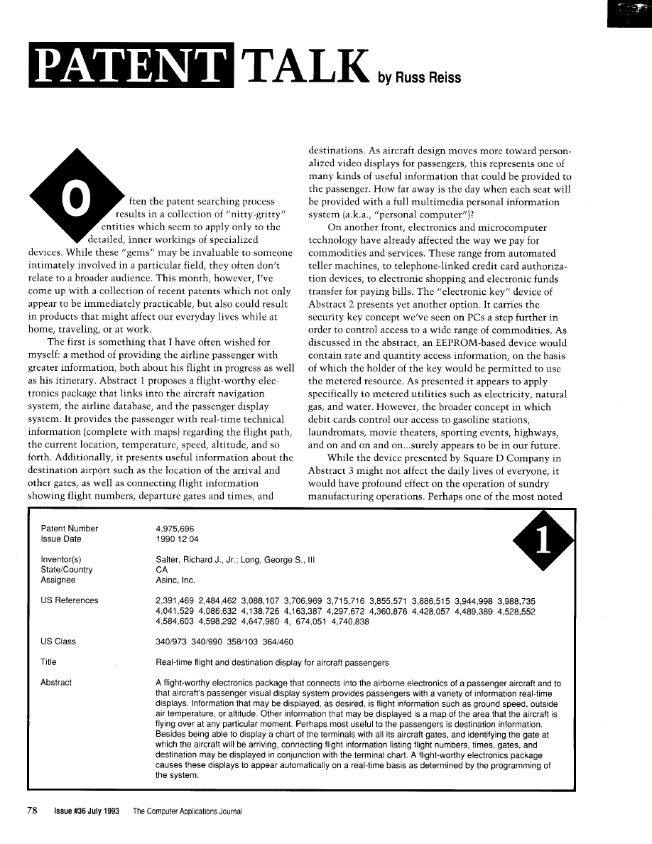
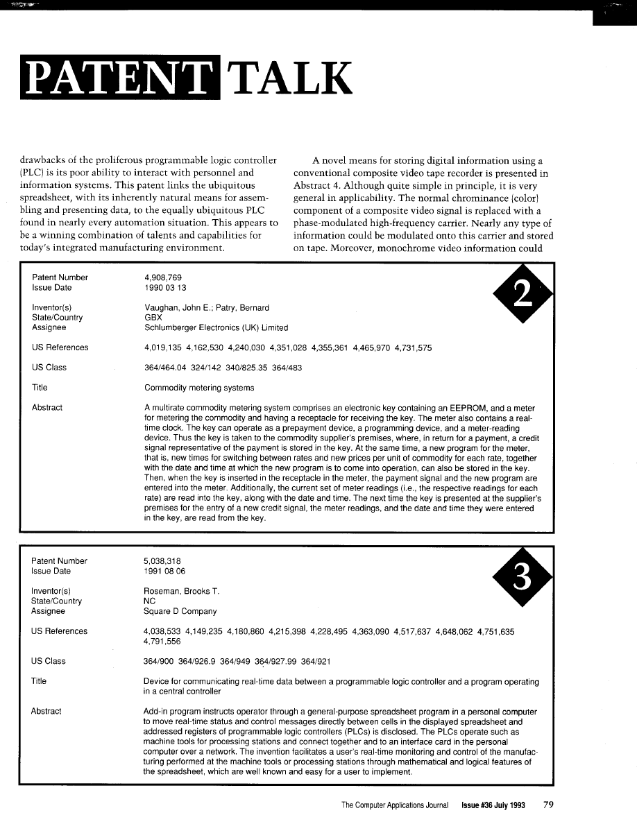

be stored as well on the same tape. While mention is made
Again in the computer video area, Abstract 5 from
of permitting the VCR to be used as a mass storage device,
Personal Computer Cameras Inc. makes your PC into an
one could also envision this technique being used to store
electronic still-video camera. Their novelty in this patent
time-stamp data or other timely information related to the
seems to stem from compression and decompression of the
recorded video information. Applications in security and
video image and its compatibility with standard PCs,
manufacturing rapidly suggest themselves.
specifically
(or compatibles) and the Apple Macintosh.
Patent Number
Issue Date
Inventor(s)
State/Country
US References
US Class
Title
Abstract
9,914
1991 05 28
Dropsy, Patrick J.
3 1 , 8 6 3
2
360133.1
System for recording and/or transmitting binary information at a high data rate via known means for
recording and/or transmitting video information, and for decoding the digital data
A method and an apparatus encode and decode binary signals representative of digital information onto or
from a high-frequency carrier wave. The carrier wave replaces the chrominance signal of a composite video
signal. Encoding and decoding of the binary signals are by phase modulation and demodulation of the
carrier wave. The method and apparatus allow simultaneous transmission of both the binary signals and the
monochrome portion of the composite video signal. The apparatus can be configured to serve as an
interface between a minicomputer and a composite video recorder, so that the composite video recorder
can be used as a mass storage peripheral.
Patent Number
Issue Date
19920811
Inventor(s)
State/Country
Assignee
US References
US Class
Title
Electronic still video camera with direct personal computer (PC) compatible digital format output
Roberts, Marc K.; Chikosky, Matthew A.; Speasl, Jerry A.
VA
Personal Computer Cameras, Inc
3581209
40
3581903
An electronic still camera comprising a lens, shutter, and exposure control system, a focus and range
control circuit, a solid state imaging device incorporating a Charge Couple Device (CCD) through which an
image is focused, a digital control unit through which timing and control of an image for electronic process-
ing is accomplished, an Analog-to-Digital (A/D) converter circuit to convert the analog picture signals into
their digital equivalents, a pixel buffer for collecting a complete row of an image’s digital equivalent, a frame
buffer for collecting all rows of an image’s digital equivalent, and a selectively adjustable digital image
compression and decompression algorithm that compresses the size of a digital image and selectively
formats the compressed digital image to a compatible format for either the IBM Personal Computer and
related architectures or the Apple Macintosh PC architecture as selected by the operator so that the digital
image can be directly read into most word processing, desktop publishing, and database software pack-
ages including means for executing the appropriate selected decompression algorithm; and a memory
input/output interface that provides both temporary storage of the digital image and controls the transmis-
sion and interface with a standard Personal Computer (PC) memory storage device such as a digital
diskette. The digital diskette is removable inserted into the housing of the camera prior top use in recording
digital image data.
82
Issue July 1993
The Computer Applications Journal
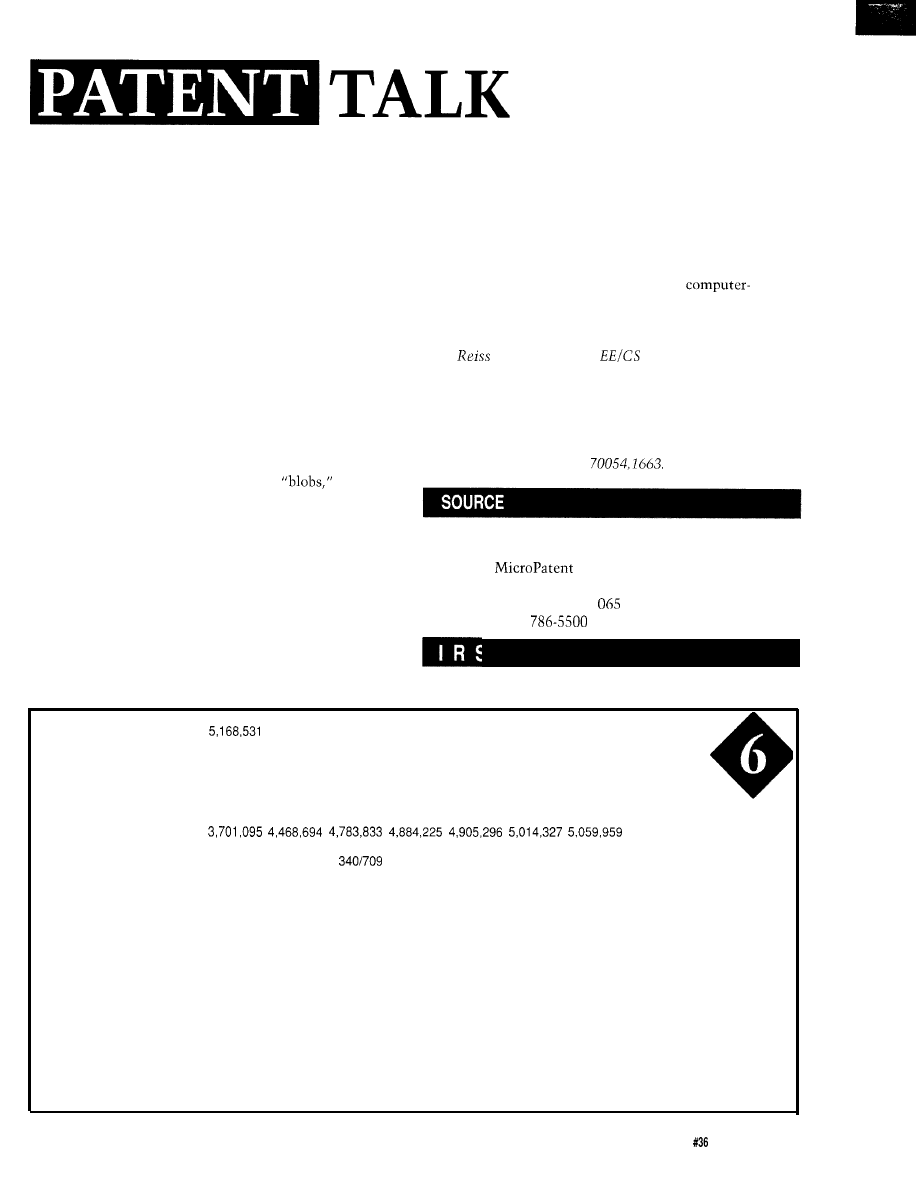
Regardless of where this particular patent fits, I do believe it
is only a matter of time before digital still-video takes its
place in our everyday life.
My professional involvement with touch-input indus-
trial display systems leads me to closely monitor new
developments in this area. Abstract 6 presents a novel way
for a user to interact with a video display by using his finger
as a pointing device. This Digital Equipment Corp. patent
apparently involves electronically capturing an image of the
user’s finger and the background field to which he is
pointing. It does not seem to be limited to pointing to a
computer display screen, and in fact might work as well or
better if he were pointing to a large control console. The
device uses some fancy image processing and pattern
matching techniques for extracting various responses from
the image. From all this, the location of
object
edges, lines, and terminated line segments are identified.
Finally, the position of a pointing object such as a finger is
recognized from all this and is used to “direct an applica-
tion program in a most natural way without the distraction
of manipulating a data input device.”
Finally, a method of correlating recorded video and
textual information is presented in Abstract 7. This “video
transcript retriever” would permit text to be searched for in
a computer transcript. It then links this text to the position
on the video recording where these words were recorded,
many diverse applications for such a device. Certainly,
educational and courtroom applications come quickly to
mind. But if one had an adequate speech-to-text conversion
mechanism available also, then any type of videotape
recording could be processed to produce a
searchable document that, in turn, could be used to index,
access and retrieve the corresponding video information.
q
Russ
holds a Ph.D. in
and has been active in
electronics for over 25 years as industry consultant,
designer, college professor, entrepreneur, and company
president. Using microprocessors since their inception, he
has incorporated them into scores of custom devices and
new products. He may be reached on the Circuit Cellar
BBS or on CompuServe as
Patent abstracts appearing in this column are from the
Automated Patent Searching (APS) database from:
25 Science Park
New Haven, CT
11
(203)
or (800) 648-6787
and then accesses that spot on the videotape. There are
422
Very Useful
423 Moderately Useful
424 Not Useful
Patent Number
Issue Date
Inventor(s)
State/Country
Assignee
US References
US Class
Title
Abstract
1992 12 01
Sigel, Claude
c o
Digital Equipment Corporation
382148 382142 382116
Real-time recognition of pointing information from video
An occurrence of a predefined object in an image is recognized by receiving image data, convolving the
image data with a set of predefined functions to analyze the image data into occurrences of predefined
elementary features, and examining the occurrences for an occurrence of a predefined combination of the
elementary features that is characteristic of the predefined object. Preferably the image data are convolved
directly with a first predefined function to determine blob responses, and a second predefined function to
determine ganglia responses indicating edges of objects. Then the ganglia responses are convolved with a
third predefined function to determine simple responses indicating lines in the image, and the simple
responses are combined with the ganglia responses to determine complex responses indicating terminated
line segments in the image. A pointing finger, for example, is recognized from the combination of a blob
response and a complex response. The method, for example, permits a data input terminal to recognize in
real time the presence, position, and orientation of a pointing finger, to eliminate the need for data input
devices such as “mice” or “joysticks.” Therefore a user can direct an application program in the most natural
way, without the distraction of manipulating a data input device.
The Computer Applications Journal
Issue
July 1993
83
Patent Number
Issue Date
Inventor(s)
State/Country
US References
US Class
Title
Abstract
5172,281
1992 12 15
Ardis, Patrick M.; Markovich, Marko R.; Thompson, Kevin W.
T N
4,941 ,125
360172.2
3641409
4
transcript retriever
A video transcript retriever includes a control unit. a control interface, a tape unit, and a display unit. The
control unit includes a control computer having a software package consisting of control software, text
software, and edit software. The control software has the capacity to permit simultaneous operation of both
the test software, which is capable of storing and searching voluminous documents, and the edit software,
which has the capacity to operate the tape unit with precision. The text software is capable of performing a
search function that at any time can provide the exact location of a specific passage within the searched
document in terms of page and line. The edit software has the capacity to provide at any time the
number prerecorded on the videotape that corresponds to a specific passage. The process for locating and
retrieving specific information on a videotape includes the steps of striping the videotape by assigning a
numerical address for every one-thirtieth
of a second segment of the videotape; indexing the words
written in a computer transcript to the words spoken on the videotape by assigning a
number to
both the computer transcript and the videotape segment where each question/answer passage begins; and
instructing the tape unit to shuttle to a precise tape location determined by the
numerical address
located during the search of the computer transcript.
Compatible with any RAM
or ROM
mapping
Runs up to 50 times faster than
the MCS BASIC-52 interpreter.
Includes Binary Technology’s
n
Memory mapped variables
In-line
assembly language
option
Compile time switch to select
805
1 or
cross-assembler
hex file
n
Extensive documentation
n
Tutorial included
n
Runs on IBM-PC/XT or
Compatible with all 8051 variants
n
508-369-9556
FAX 508-369-9549
Binary Technology,
P.O. Box 541
l
Carlisle, MA 01741
At last!
Real time industrial control for your P.C.
under Windows or DOS
The I/O Bits
Machine Programming System
Bits is the innovative software using icon base
programming that turns any IBM PC compatible into
powerful real time controller for mechanisms an
machines.
l
Intuitive “flow diagram” style programming
using easy-to-understand icons
l
Program your machine without ladder
diagrams or coding.
l
Test machine operation in minutes or hours
l
Full function industrial control elements
l
On-line help with examples and tutorials
l
Use the printer port and get 17 I/O lines for
free.
Bits for the parallel port.
$99.
I/O Bits for Mechanisms
$499.
Position Sensitive Robots, Haverhill, MA
508-521-9580 voice, 508-521-9584 fax.
84
Issue
July 1993
The Computer Applications Journal

The Circuit Cellar BBS
bps
24 hours/7 days a week
(203)
incoming lines
Vernon, Connecticut
This month in
we stat-t off with a discussion of
grounding issues and noise. How many times have you attributed a
problem to noise?
Next, we talk about the best way to make a homemade
accelerometer. turns out require more mechanical than electrical
skills.
Third is a thread about winding matching transformers for an
power amplifier. We don’t often stray into high-frequency analog
design, so there are some interesting tidbits in this one.
Finally, there are many methods for defecting the zero crossing
of an AC signal. Which is the right way for you?
To ground or not to ground
From: RONALD HORNER To: BOARD DESIGNERS
have
controller board that I built and I am not
sure if I should ground the chassis of the enclosure to the
same ground as on the 5-V supply or the DC 5-V power
supply? I have been told that all grounds should be com-
mon, but I wonder if some isolation of the 5-V supply
should be considered to prevent noise from entering the
system?
From: ED NISLEY To: RONALD HORNER
think the answer is “it depends”-how’s that for
advice?
From a safety standpoint you want the enclosure
connected to earth ground so it cannot become “hot” if it’s
shorted to a power supply. If any of your connectors use the
enclosure as the common side, you want it connected to the
logic ground to minimize the noise injected into the inputs.
ESD and EM1 considerations tell you to keep all signal
currents off of the enclosure, but connect it to the power
supply common so it shields the circuitry.
You pay your money and you take your options..
leaving the enclosure floating is a bad idea on all sides!
From: RONALD HORNER To: ED NISLEY
Yes,
I
always ground the enclosure to earth ground or
the same ground on the neutral/ground of a 120-V side, but
the low voltage? Shouldn’t the 5-V ground not be part of the
enclosure ground?
From: JAMES MEYER To: RONALD HORNER
If you are going to make connections to the outside
world, the best way is with optically isolated I/O modules.
If you do that, then there is no necessity to ground the
supply to any part of the chassis.
From: RONALD HORNER To: JAMES MEYER
Right, that’s what I believe in for absolute integrity!
From: ED NISLEY To: RONALD HORNER
To ground or not, that is the question!
I know I’ve had trouble with widgets on my desk that
came about because they were not referred to power line
ground. After I added a few clip leads here and there, the
mysteries Went Away.
Betcha Pellervo has some cogent observations on this
topic dating back to when he did something involving
kiloamperes and megavolts! Come in, Pellervo..
From: RONALD HORNER To: ED NISLEY
You know, I don’t believe that ground is really ground.
I mean, in my experience “ground” is only an antenna to
draw in more noise. I like isolation. Absolute isolation
using fiber optics, optical encoders, isolation transformers,
and the like. Everybody has their theories on the stuff, but
for me it’s always trouble.
From: ED NISLEY To: RONALD HORNER
Yeah, Steve’s opinion on isolation is that a laser diode
across the driveway beats a half-inch copper ground strap
any day...
From: PELLERVO
To: RONALD HORNER
The unfortunate side effect of the term “grounding” is
that several people expect a connection to a ground rod to
The Computer Applications Journal
July 1993
85

solve all their interference problems. That simply is not
possible. Maybe a term such as “return path” would be
more appropriate. Even then, you have to realize there are
different mechanisms of noise coupling. All of that, of
course, is covered by a gentleman named Maxwell (which
coverage, by the way, was the basis for Einstein and his
grand achievement).
Frankly, any and all signals are referenced to SOME-
THING. If you use an optocoupler, your reference is closer
to the place where you need your signal, but the reference is
still physically there. Now, generally the difficulties people
have with “grounding” is because their signals run through
too long, or mixed, paths or there are more signals than the
one of importance to you in the common path (the
“ground”). If you can make a truly zero impedance (not only
resistance] for your “ground,” there would be no
In real life, you cannot defeat inductance in any
physical length of wire, whatever thickness, so you are
bound to get voltage drops along the length of it. If you
happen to have two of the wires, to establish an indepen-
dent reference, you start seeing the signals and interference.
The different types of noise coupling that I have been
dealing with are direct voltage drop in common runs,
capacitive coupling to nearby high-impedance circuits, and
inductive coupling between parallel wires or wire loops.
You might add a radiated signal (i.e., your “antenna”], but
that is just a generalized case of the inductive and capaci-
tive coupling mechanisms. And the remedies are slightly
different depending on the MAIN mechanism of coupling.
Electrostatic (capacitive) coupling is combated with
increased distance, either physically or by shielding, and/or
changed impedance levels at the receiving side.
Electromagnetic coupling is reduced by reducing the
loop size. The traditional use of twisted pairs is the prime
example. It is effective for both the transmitting and for the
receiving side. Your use of optocouplers works also partly
on this principle, reducing the loop size. Another way is to
reorient some of the wire runs. Make the signal line run
across the noisy line rather than along with it.
As far as the common grounding rules go, they are not
necessarily optimum for some signal situations, but they
are necessary for the safety. There is another loop or return
path that is mandatory. In fact, your desire to separate your
signals (“not grounding”) is one way of reducing the
coupling through a shared path. The power line grounding
efficiency varies greatly and the resistance is always large
enough to cause problems to the unwary.
Basically, use common sense for selecting the points of
signal common and do some experimentation, like Ed
suggested, with clip leads and you may find a point that
pretty much counterbalances the stray signals your power
supply and other necessities cause. Once you have found a
86
Issue July 1993
The Computer Applications Journal
good point, you may be able to use that until you make
some (almost any) changes to your circuit.
From: RONALD HORNER To: PELLERVO
Thanks for the info. What you said pretty much sums
up what I know and suspected. I’ll be doing more research
on this. The main problem I have had is one of credibility!
Noise appears to be both a hidden problem for machines
that don’t work, but it is also used as an excuse for bad
programming or a bad design. So, I am starting to gather
some written material from professionals on their studies
and experiences to use as a wedge between the truth and
the fairy tales.
From: RUSS
To: RONALD HORNER
Wow! You struck a sensitive nerve with that remark!
While it’s commonplace for programmers and engineers to
point fingers, one at the hardware and the other at the
program, it seems they BOTH love to blame “noise” for any
problem that cannot be identified within a short time! I
have seen precious few cases of true noise problems, and
those that have appeared were usually the result of poor
engineering practices by neophyte designers. Your compen-
dium could be a real service to newcomers on how to do it
right!
As a postscript, while sometimes necessary to get a
product out the door, I don’t see “software filtering” as a
cure-all solution to inadequate hardware design, either.
Accelerometers
From: STEPHEN PHILLIPS To: ALL USERS
I would like to use a strain gauge as an accelerometer.
The sensitivity would have to be high (for my ignorance of
these devices, I could be wrong). Since f =
and the mass I
intend to use is 1 gram, this would mean a strain gauge at
least capable of sensing
of a Newton. I do not
expect a force grater than 1 N ever being placed on the
strain gauges (however, you never know].
I would like to use these to detect sudden (i.e., erratic)
changes in the stability of a model airplane. I intend to
process these changes by comparing them with some preset
tolerance. A computer will decide what action is necessary.
Since the moment of inertia is large enough, the computer
would not need to be fast since a resolution of
of a
second goes beyond the timing of pulses to standard
hobbyist servos.

From: TOM
To: STEPHEN PHILLIPS
A home-brewed sensor could be made from a piezo
crystal taken from a buzzer:
Mass
Surface that moves
This could be used as an accelerometer for a single axis.
You might have to electrically filter out some of the
resonant vibrations that will be coming out of it also.
Increasing and decreasing the mass will change its
sensitivity.
From: STEPHEN PHILLIPS To: TOM
Hadn’t thought of cheap piezo elements. I need to
measure fairly small changes. I was planning on converting
the output into a PWM signal for a small computer to
process. The output of the sensor goes to a sample-and-hold
circuit. Then that reference is converted to a PWM signal
that is read by a computer, which of COURSE converts it
into some value that has meaning to the computer.
Any way of projecting the sensitivity? Trial and error, I
suppose. What
I
want to do is use a small computer to
stabilize a model plane that is inherently unstable.
From: PELLERVO KASKINEN To: STEPHEN PHILLIPS
Using strain gauges for an accelerometer is mainly an
exercise in handiwork. You need to build either a mem-
brane or a reed that is anchored at one end (rim, in case of
the membrane) and has your mass attached to the other end
or center. There has to be enough room for the strain gauge
elements to be glued to opposite sides of the flexing
member. Thereby they become elongated/compressed with
any deflection of the support member and a half-bridge or a
full-bridge circuit can be used to measure the relative
difference.
The strain gauges that I have used were capable of
producing up to
10%
change in resistance before failure,
provided the glue was equally good. You could count on
reaching over 1 but don’t need that much with good
amplifiers, even with DC coupling. I recommend an OP-27.
When I did use the strain gauges more often, I had a
commercial AC excitation bridge instrument. But I have
done or seen some pretty good DC-coupled units as well.
One of them even used a frequency-modulation principle to
send the strain indication from a moving shaft via radio.
The key issue is selection of your materials. Too thin a
membrane appears to give a high sensitivity, but loses some
of it because the strain gauges on the opposite sides are not
affected as much as they would be if attached to a thicker
membrane with the same flexing. Also note that if you
anchor two ends of a reed solidly, then the center moves
very little under a transversal force. If you can, use only one
anchored end. Otherwise, you better make some pivoting
help (i.e., convolutions). The strain gauges should be
mounted as close to the maximum BENDING position as
possible. In the single-end reed case, it is as close to the
fixed mounting as possible. Run the connection leads away
from the mounting.
So, pick up some shim stock, probably about 0.004” to
0.006” stainless steel would be a good starting point. Cut it
to the width of the strain gauges and anchor one end of a
longer-than-your-final-target piece. Attach your mass to
different positions and start shaking the construct. Try to
evaluate the amount of deflection resulting. Cut the strip
shorter. Is it still flexing OK? If yes, cut it more until you
have reached the smallest practical size that seems to do
the job. Then glue the strain gauges in place with good
epoxy (probably requires the regular
cure variety).
For the final implementation, you probably don’t need
to worry about excessive deflection, but if you do, just put
mechanical stops on each side of the free end at suitable
distances.
I hope this is not too cryptic without a picture. Just
don’t have time to do any ASCII graphics.
From: JAMES MEYER To: PELLERVO KASKINEN
The only thing I would add to your excellent tutorial is
a word about resonance. Homemade accelerometers often
suffer from insufficient damping. Putting a strain gauge on a
piece of springy shim stock is asking for a big resonant
response at some frequency. Murphy says that that response
*will* be in the center of the range of signals that you’re
trying to measure.
The cures are varied. Most often involving some sort of
added semiviscous material. Testing and curing those
resonances is partly responsible for the cost of commercial
accelerometers.
RF transformers
From: TERRY NORRIS To: ALL USERS
As part of my continuing training as “Jack of All
Trades, Master of None,” I have recently been given the
simple task of building an RF power amplifier. Luckily, I
The Computer Applications Journal
July1993 87
found a schematic for exactly what I need. Alas I don’t
know how to build the matching transformer.
Book description:
20 turns
coax cable,
bifilar on
micrometals T-50-6 toroid.
T2: 1 turn of two
coax cables in parallel
through two balun cores stackpole
From: JAMES MEYER To: TERRY NORRIS
First, get all the parts you’ll need. Check out some ham
radio magazine advertisements.
uses ordinary enamel insulated “magnet” wire.
Bifilar means to take two (bi) wires (filar) long enough to
make 20 turns and twist them together with about one or
two twists per inch. Take the twisted wires and wind them
20 times through the toroid. Space the turns out to fill the
toroid. If you use wires of different colors, it will make
identifying the windings easier. The start and end of each
winding is important when the connections are made. My
guess is the starts are on one side of your drawing and the
ends are on the other.
T2 is a bit more complicated. In fact, I can’t help you
there without a little more info. Try another message with
a drawing for T2.
From: TERRY NORRIS To: JAMES MEYER
Alas, the schematic symbol for T2 is the same as
Also, I was thinking about the word bifilar wound. Isn’t
that the winding technique on noninductive wirewound
resistors?
13748
In that case, just use the description of and change
From: JAMES MEYER To: TERRY NORRIS
the number of turns.
No. It isn’t. “Bifilar” simply means “two wires.”
Usually side by side, and wound at the same time.
If T2 is shown on the schematic exactly like
then
the author must not have been using the coax as anything
other than large-diameter wire. By that I mean the shield
and center conductor at each end of the cable must have
been connected together.
From: RUSS
To: TERRY NORRIS
You seem to be having problems with the meaning/
construction of these “transmission line transformers,”
particularly T2, which uses coax as the transmission line.
First off, there are a few good books on the subject, if
you should like to become an “expert.” The “bible” is Jerry
“Transmission Line Transformers” published by
ARRL. Then there are the many excellent/practical/
readable books by Doug
which address this and
solid-state RF amplifiers in great PRACTICAL detail. I
suggest his “Practical RF Design Manual” published by
Prentice-Hall.
But let’s take a look at your transformer. If you, for a
moment, reverse the “input” and “output” and feed a signal
into the OUT/GND terminals, you can see that it is
impressed across the lower inductor. Due to the phasing of
the two windings and the transformer action, a similar
voltage should be coupled to the upper coil in such phase
that it ADDS to the applied signal producing twice as much
voltage at what you have shown as the “input” terminal
(with respect to ground). Due to conservation of power (if
there were no losses), twice the voltage must mean there is
half the current. So the impedance is
or four times
what it looks like on the right-hand side. Thus (using your
I/O specification], we can consider this a
impedance
ratio matching transformer (or 4: I going the other way from
out to in). You can use it in either direction, it doesn’t
depends on your application and if you are
stepping UP or DOWN the impedances.
The design of these transformers is not critical unless
you are looking for optimum power transfer, very wide band
Now, what about the transmission line? Doesn’t
matter much if it is bifilar (parallel wire) line or coax. The
bifilar approach does not REQUIRE that the wire be
twisted. That makes it more convenient to work with and
somewhat lowers the characteristic impedance of the
transmission line it represents. Coax comes in only some
characteristic impedances, and 50 ohms is very common.
Since, for T2, they wanted
coax, they simply
paralleled two pieces of coax, connecting inside to inside
and outside to outside at each end, and then consider it a
SINGLE piece of
coax. You could also buy and use
coax such as Microdot
If you
choose to use paralleled
cable, I suggest RG- 174-U
for low-power applications. Just be VERY careful when
soldering to it (that you don’t melt the inner insulation and
short inside to outside], and consider a dab of RTV at the
ends to both seal it against moisture and to strain-relieve
the end where it is often subject to stress, If you use bifilar
wire, you can expect rough characteristic impedances of
around 30 ohms for
wire and 60 ohms for
wire.
issue
July 1993
The Computer Applications Journal
operation, and so forth. Typically, the characteristic
impedance of the cable used is equal to the square root of
the in/out impedances. My guess is your circuit is matching
12.5
ohms to 50 ohms, which would require the use of
ohm coax
12.5 *
But these have been built with
widely different cable and still work well. What you want is
a line length that is short compared to a wavelength at the
highest frequency it will pass, and yet sufficient inductance
(due to number of turns and the core permeability) to block
circulating currents at the lowest frequency of interest. But
again, I say it’s NOT critical!
Hope that gives you something to get started with.
There are a wide variety of these transformers-in both
unbalanced or balanced form at both input and output. The
widely mentioned BALUN transformer is a
to
form of these, and may have 1: 1 or other
transformation ratio, as required.
From: RUSS
To: TERRY NORRIS
In my other message I forgot to answer what is perhaps
your biggest question with respect to using coax in a
transmission line transformer. How do you connect the
coax!? Well, if you followed my discussion there, you see
that it doesn’t really matter what the transmission line
parallel wires or coax. In either case, there are TWO wires
and they are wound “bifillarly” through the core. In the
case of coax, one wire is the outer conductor, while the
other is the inner conductor. So, to get the phasing correct,
you will need to connect the inner conductor at one end of
the coax to the outer conductor at the other end AFTER
winding it through the core.
Zero-crossing detectors
From: GREG PRICE To: ALL USERS
Any ideas out there on a simple circuit to detect the
zero-crossing point of the AC signal so I can switch a
nonlatching relay on and keep it on until a control signal
(8255 buffered) goes low. Thought about an AND gate with
a flip-flop or a PAL. I am sure this has been done many
times and many ways. Any help would be appreciated.
From: JOHN CONDE To: GREG PRICE
Well, the easiest way I know of to detect the zero cross
would be with a zero-crossing detector chip (3059 or 3079, if
memory serves). This will output a pulse when the signal
crosses zero (in either direction). The pulse can gate an SCR
which will keep your relay on. Turning it off is another
problem; the simplest would be to have the control signal
supply the current to the relay (through the SCR), then
when the signal went low, the SCR would turn off and the
relay would drop out. Of course, if the control signal can’t
supply enough current, you can have it control a transistor
that will. Hope this helps.
From: PELLERVO
To: GREG PRICE
First, get a zero-crossing signal as a narrow pulse. Then
feed it into the clock input of a D-latch or make one out of
a pair of
NAND gates. One input on each for data, a
second one for the cross connection, and the third one tied
together for the clock.
I used an optocoupler to provide the basic zero detec-
tion, or actually the signal polarity detection. I fed the
output to an XOR directly to one input and through a
ms RC time constant filter to the other input. Got 0.1
narrow pulses on every zero crossing.
From: LARRY G NELSON SR To: GREG PRICE
How about a Motorola
or similar. These are
optoisolators with zero-crossing detect and
output.
Not sure the exact part number you would want, but this
could be the ticket for what you are looking for.
We invite you call the Circuit Cellar BBS and exchange
messages and files with other Circuit Cellar readers. It is
available 24 hours a day and may be reached at (203)
1988. Set your modem for 8 data bits, 1 stop bit, no parity,
and 300,
9600, or
bps.
Software for the articles in this and past issues of The
Computer Applications
may be downloaded from
the Circuit Cellar BBS free of charge. For those unable to
download files, the software is also available on one 360K
IBM PC-format disk for only $12.
To order Software on Disk, send check or money order
to: The Computer Applications Journal, Software On Disk,
P.O. Box 772, Vernon, CT 06066, or use your VISA or
Mastercard and call (203) 8752199. Be sure to specify the
issue number of each disk you order. Please add $3 for
shipping outside the U.S.
425 Very Useful
426 Moderately Useful
427 Not Useful
The Computer Applications Journal
Issue
July 1993

hile don’t claim to be any sort of an economist, still can’t help but think of world events in terms of
mathematics. I guess my math professors would be proud of me for that. One “formula” have been attempting
to understand lately is the following set of relationships and what they mean:
Consumer willingness to purchase and their satisfaction is inversely proportional to computer pricing. Computer pricing trends are
inversely proportional to profit margins. Consumer satisfaction is proportional to profit margins. The derivative of reduced computer
pricing is increased consumer performance expectations. Increased consumer expectations has a direct linear relationship to a
vendors need to invest heavily in R&D, which is inversely related to quarterly profits. Companies driven by margins must raise prices
or cut costs.
Based on the first relationship, cost cutting is the only alternative for many. This means staff reductions or using lower-cost
materials. Lower-cost materials means lower quality (in some cases), which is inversely proportional to consumer satisfaction.
cost materials is inversely proportional to company profits? Lowered staff counts leads to lower morale. Lower morale is inversely
proportional to productivity. Lowered productivity is inversely proportional to company profits. What a no win situation!
As you can see, this is a complex set of relationships with many interrelated factors. Although still haven’t found any unifying
factors that lead to a steady state or predictable response curve for the equations, I doubt anyone else has yet, either. Witness the
recent turmoil in the appliance (er, commodity) market for home computers. Tumbling prices, fallen kings, paradigms shifting as rapidly
as the Sahara sands, and former industry powerhouses crippled in the channel and bailing water. This state of affairs has got to have
the marketing and accounting departments quaking in their shoes.
I remember attending one seminar where it was said that if the car industry had advanced as rapidly as the computing industry,
you would be able to buy a car that was the size of a matchbox, went 500 miles an hour, and cost about a dollar. Car prices are going
up and things haven’t changed much. Computer prices are avalanching downward and performance is skyrocketing.
Dog eat dog is one thing, but an industry eating itself alive is quite another. Many pundits claim that the consumer is benefiting
from this chaos with more MIPS and computing power on their desk than most nations were able to afford as few as twenty years ago.
But I wonder, if many companies fall by the wayside, or simply give up, from this unbridled shake
the truly gifted
developers look for more peaceful pastures to explore, thus slowing the pace of innovation? Will this reduction of players in the
marketplace lead to a kind of Orwellian nightmare of one company providing the computing platforms. Imagine if the Post Office were
the ones in charge of computing development....price increases without a lot of performance gains. Not a pretty sight.
So are all of these signs indicative of a vibrant, exciting market? Or is this chaos a portent of things to come? Well, a lot of these
companies started out in garages. Maybe some of them will be back there again soon.
96
Issue July 1993
The Computer Applications Journal
Wyszukiwarka
Podobne podstrony:
circuit cellar2001 07
circuit cellar2000 07
circuit cellar1995 07
circuit cellar2002 07
circuit cellar1993 07
circuit cellar1994 07
circuit cellar1996 07
circuit cellar1997 07
circuit cellar2004 07
circuit cellar1994 07
circuit cellar2004 07
circuit cellar1996 07
circuit cellar1995 07
circuit cellar1997 07
więcej podobnych podstron