Approach Chart - Plan View
The plan view is a graphic picture of the approach, usually presented at a scale of 1 in = 5 NM. Plan
views at scales other than 1 in = 5 NM are noted. Latitude and longitude are shown in 10 minute
increments on the plan view neatline. Symbols used in the plan view are shown below.
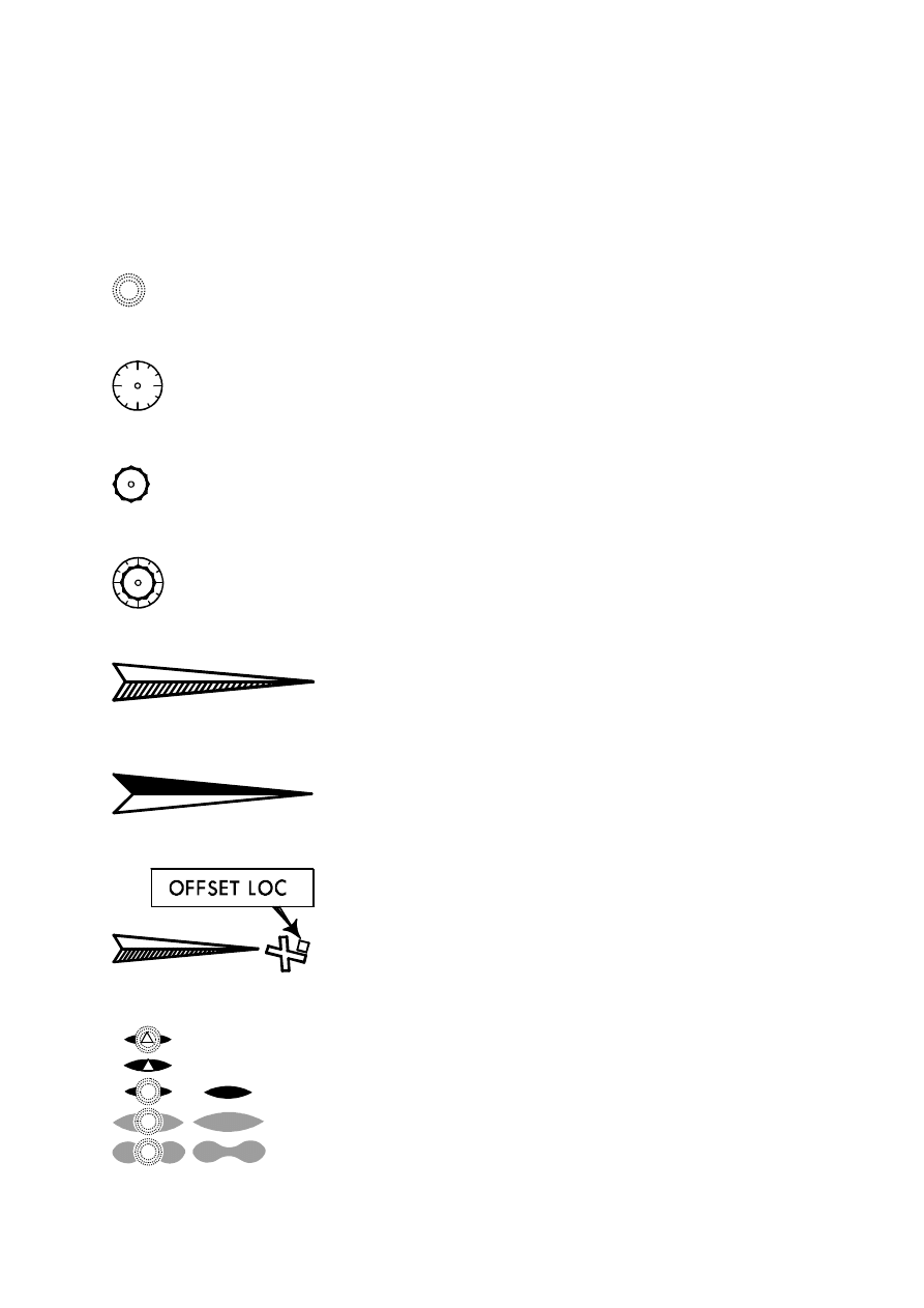
NAVAIDS
NDB (Non-Directional Radio Beacon)
VOR (VHF Omni-Directional Range)
TACAN (Tactical Air Navigation facility) or DME (Distance Measuring Equipment)
VORTAC or VORDME
ILS, LOC, LDA, SDF, MLS
or KRM Front Course
LOC Back Course
Offset Localizer
Markers with or without locator, NDB or intersection. The triangle in a marker or NDB symbol
represents co-located intersection.
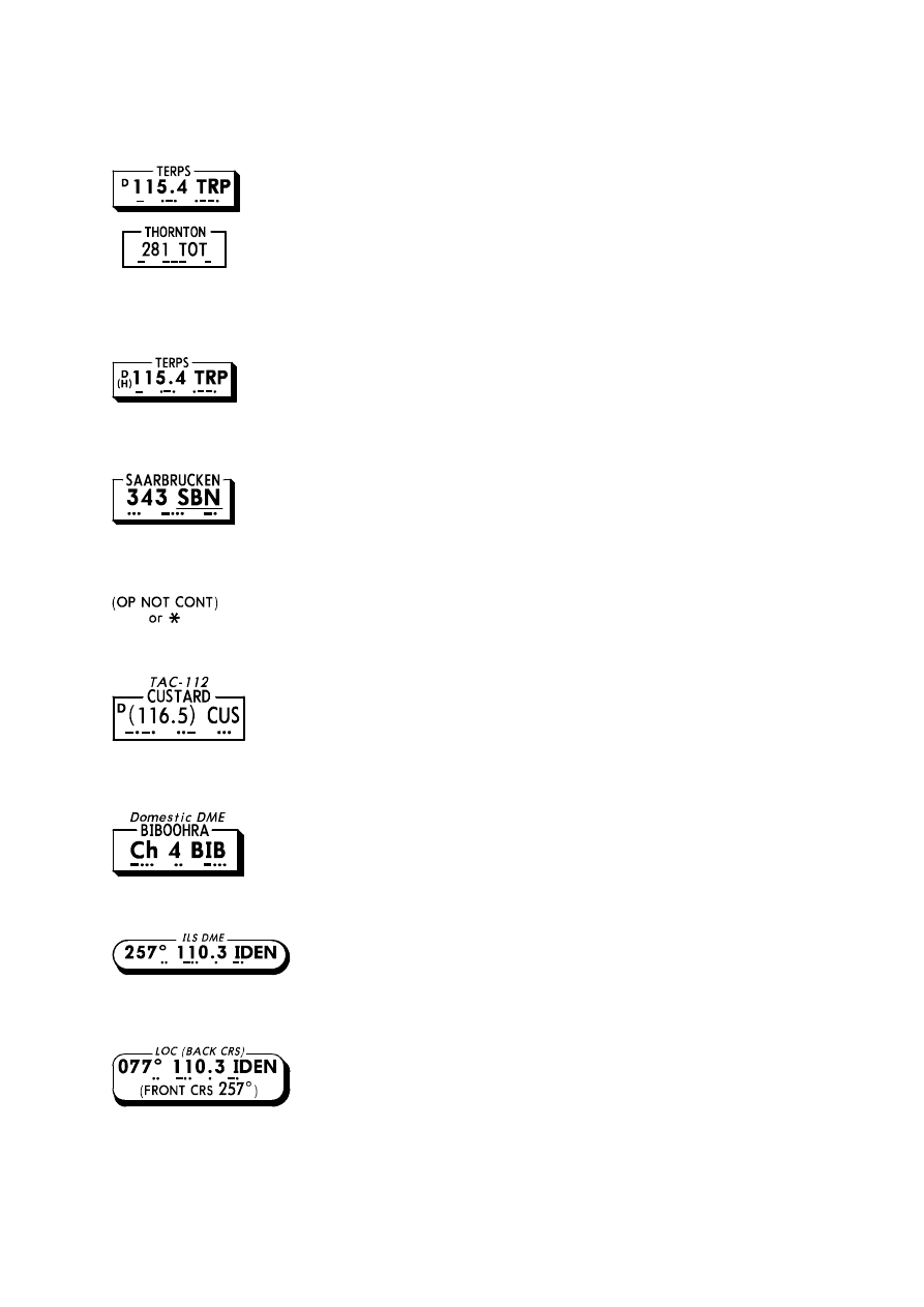
Navaid facility boxes include facility name, identifier, Morse code and frequency. The shadow
indicates the primary facility upon which the approach is predicated. In VORTAC and VORDME
facility boxes the letter "D" indicates DME capability.
VOR, VORTAC and VORDME class is indicated by a letter "T" (Terminal), "L" (Low Altitude) or "H"
(High Altitude) when available.
Underline shown below navaid identifier, indicates Beat Frequency Oscillator (BFO) required to hear
Morse Code identifier.
Indicates part-time operation.
TACAN facility box with "Ghost" VOR frequency for civil tuning of TACAN-only facilities to receive
DME information.
Australia Domestic DME Operates on 200 MHz and requires airborne receiver specific to this system.
ILS, LOC, LDA, or SDF facility box. It includes inbound magnetic course, frequency, identifier, and
Morse code.
Localizer Back Course facility box. Front course included for HSI setting.
MLS facility box including inbound magnetic final approach course, MLS channel, identifier with
Morse code and VHF "Ghost" frequency for manually tuning DME.
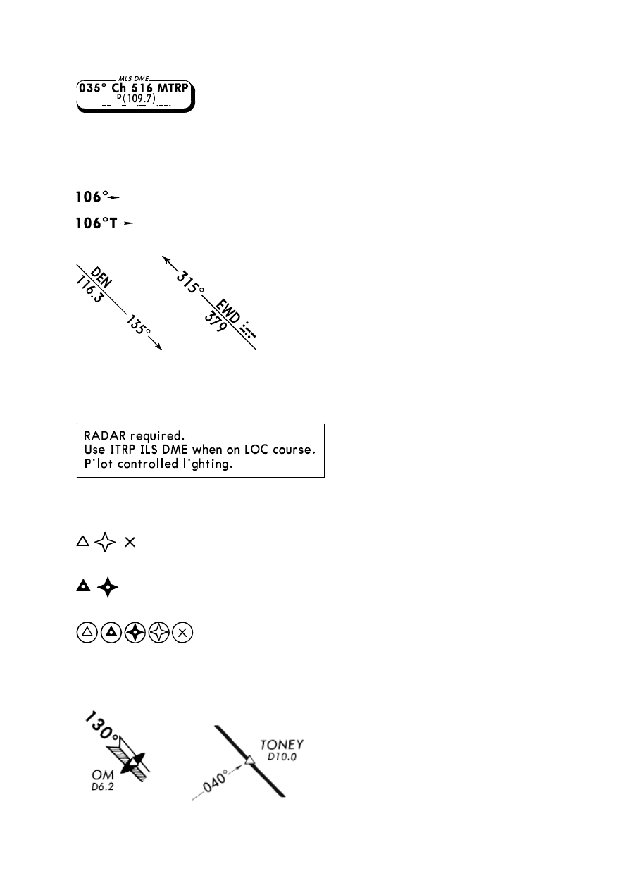
BEARINGS
Magnetic Course
True Course
VOR cross radials and NDB bearings forming a position fix are "from" a VOR and "to" an NDB.
Morse code ident is charted on VOR radial/NDB bearing when forming facility is outside of planview.
On charts dated on or after 10 MAR 95, General procedure NOTES are contained within a single box
in the planview. NOTES specific to a single item on the chart are associated with that item.
AIRSPACE FIXES
Non Compulsory Airspace Fixes.
Compulsory Airspace Fixes.
Fly-over Airspace Fixes.
DME value will be portrayed as D10.0. When fix and co-located navaid name are the same, only the
navaid name is displayed.
Allowable substitutions for identifying a fix are noted in the planview. At the pilot's request, where
ATC can provide the service, ASR may be substituted for the OM. In addition, PAR may be
substituted for OM and MM.
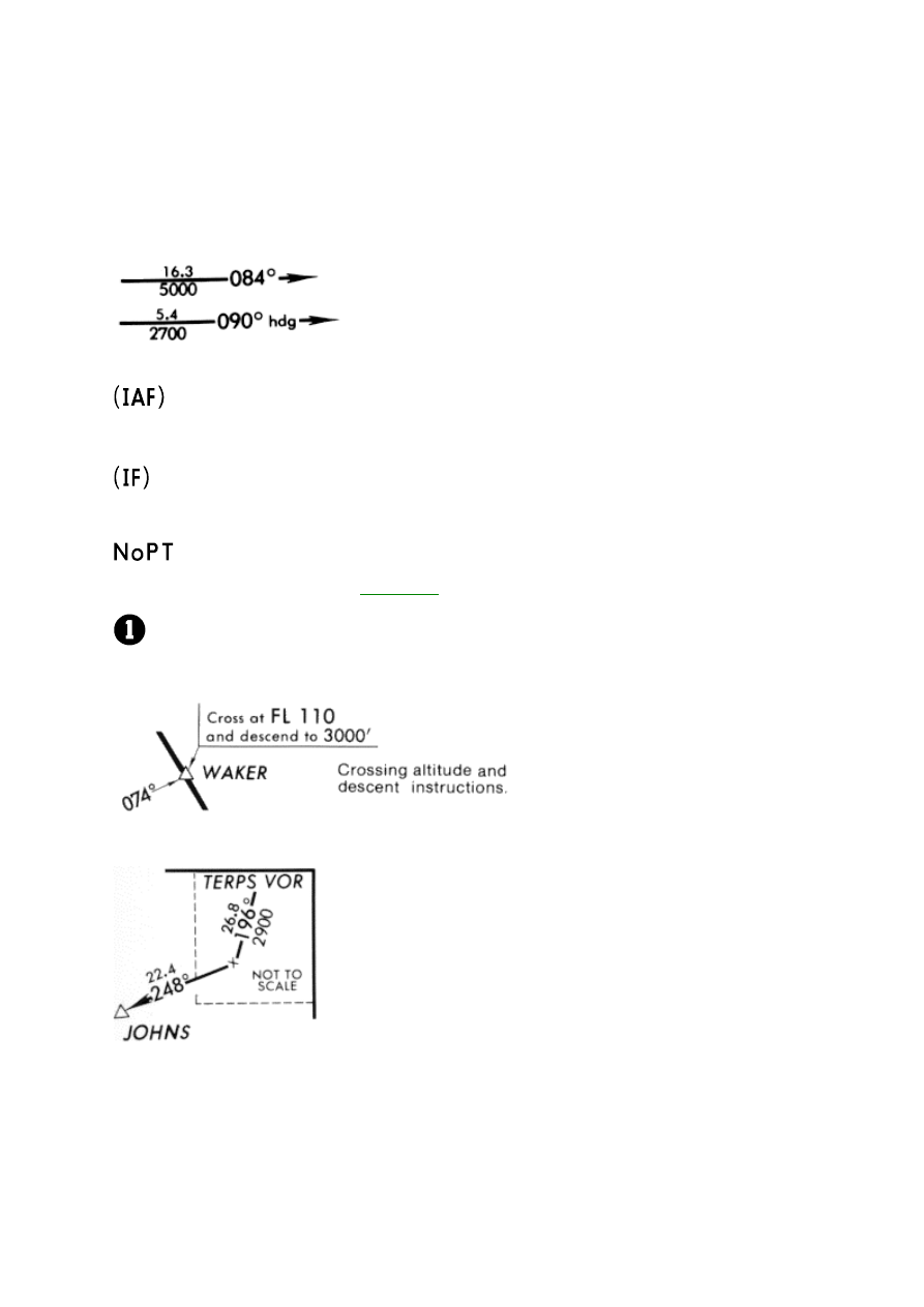
APPROACH TRANSITIONS
Click on a text item or symbol in the illustration below for more information.
Initial Approach Fix
Intermediate Approach Fix
No procedure turn, Race track pattern or any other type of course reversal procedure required or
authorized without ATC clearance. (
See Below.
)
Flag notes -see applicable reference notes elsewhere on the plan view.
Crossing altitude and descent instructions.
Approach transition inset. (Dog leg route, with off-chart turn). Also provided when route originates at
an off-chart intersection designated only for approach use - such fixes are not charted on enroute
and area charts.
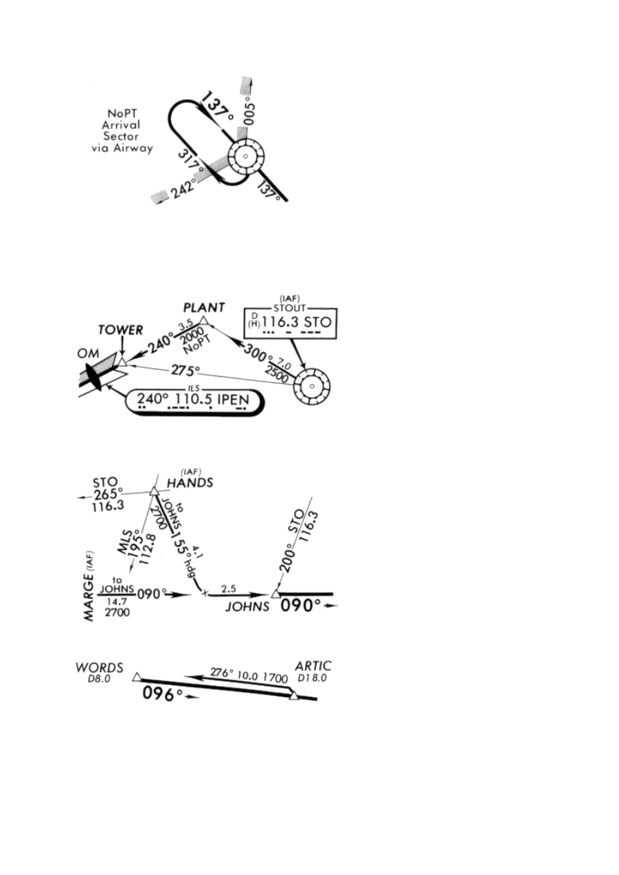
NOPT arrival sectors depict an area of approach transition routing to an approach fix. No procedure
turn, Race Track Pattern or any type course reversal is required nor authorized without ATC
clearance when an arrival course is within the charted sector and on an established airway radial to
the fix.
Approach transition track, distance, and altitude from a defined fix is illustrated below.
Note that the routes from STO to Plant to Tower are approach transitions, whereas the STO R-275
is not an approach transition. The STO R-275 has a small arrowhead and is a cross radial forming
Tower. The STO R-300 has a large and small arrowhead indicating both an approach transition and
a cross radial forming Plant. Plant and Tower are also formed by the IPEN localizer course.
An approach transition coincidental with the approach procedure flight track is charted offset from the
flight track for clarity.
Approach transition. Route from Enroute Navaid or Fix to Initial Approach Fix (IAF).
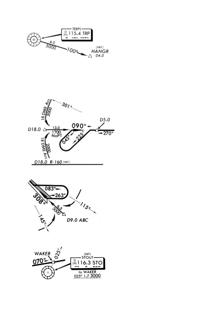
Approach transitions via DME arcs are illustrated below with distance from facility, direction of flight,
start and termination points of the arc. DME arc altitude is maintained until established on approach
course.
Lead radials may be provided as an advisory point for turning to the approach course.
Approach transitions may be described under the originating navaid with course, distance, altitude.
and terminating point.
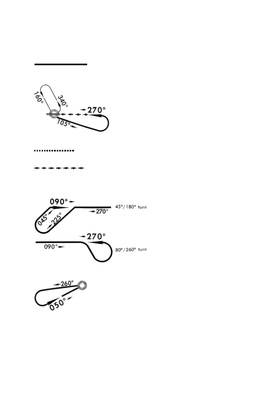
APPROACH PROCEDURE FLIGHT TRACK
The approach procedure flight track is portrayed by a bold line. This
track begins in the plan view at the same location where the profile begins.
Holding pattern used to lose altitude prior to proceeding outbound on the approach.
High level approach track
Visual flight track
PROCEDURE TURNS-COURSE REVERSALS
Schematic portrayal of procedure turn
Tear drop or Base turn. When course reversal is required, it must be flown as charted.
Holding pattern or Racetrack pattern. When course reversal is required, it must be flown as charted.
When a procedure turn, Racetrack pattern, Tear drop or Base turn is not portrayed, they are not
authorized.
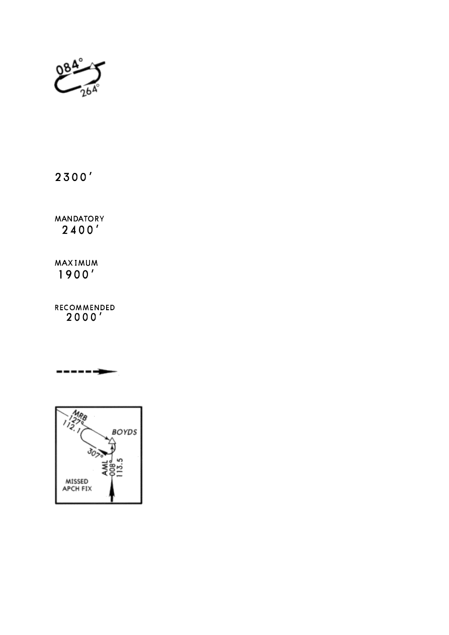
ALTITUDES
All altitudes in the plan view are"MINIMUM"altitudes unless specifically labeled otherwise.
Altitudes are above mean sea level in feet. May be abbreviated "MIM"
Mandatory altitudes are labeled "MANDATORY" and mean at the fix or glide slope intercept.
Maximum altitudes are labeled "MAXIMUM." May be abbreviated "MAX."
Recommended altitudes are labeled "RECOMMENDED."
MISSED APPROACH
Initial maneuvering course for missed approach. Details of the missed
approach are specified below the profile diagram.
Missed approach fix inset.
HOLDING PATTERN
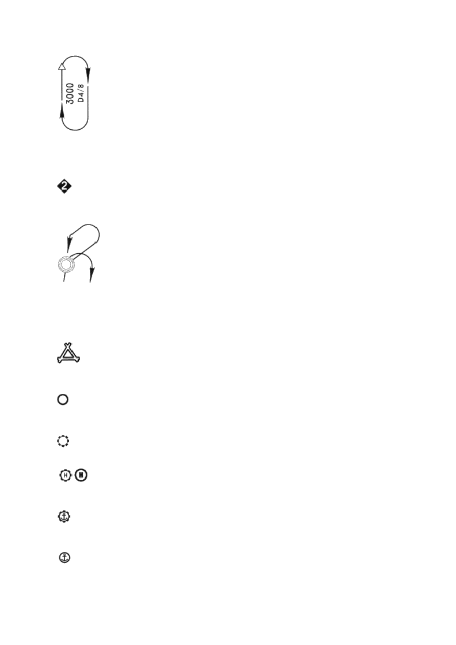
Holding pattern not part of the approach procedure. DME figures, when provided, give the DME
distance of the fix as the first figure followed by the outbound limit as the second figure. 3000
indicates the minimum holding altitude, (MHA).
Length of holding pattern in minutes when other than standard.
Holding patterns are generally not charted to scale.
Indicates procedure for leaving the holding pattern.
AIRPORTS
IFR airports in the area and VFR airports underlying the final approach are depicted.
Airport to which the approach is designed
Nearby Military airport
Nearby Civil or joint use Military airport
Heliport
Civil Seaplane Base
Military Seaplane Base
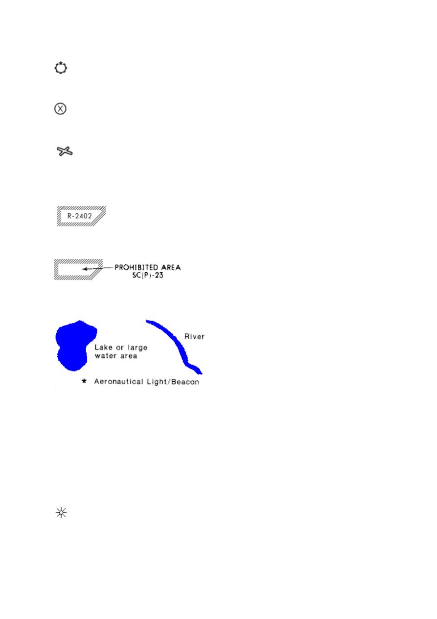
Airport with light beacon
Abandoned or closed airport
An airport reference circle, 5 statute miles in radius, centered on the airport. Omitted after 1 OCT 93.
AIRSPACE
Restricted airspace (Refer to the enroute chart for limitations.)
Prohibited Area
ORIENTATION DETAILS
TERRAIN HIGH POINTS AND
MAN-MADE STRUCTURES
1.
Some, but not all, terrain high points and man-made structures are depicted, along with their
elevation above mean sea level. THIS INFORMATION DOES NOT ASSURE CLEARANCE ABOVE
OR AROUND THE TERRAIN OR MAN-MADE STRUCTURES AND MUST NOT BE RELIED ON
FOR DESCENT BELOW THE MINIMUM ALTITUDES DICTATED BY THE APPROACH
PROCEDURE. Generally, terrain high points and man-made structures less than 400 feet above the
airport elevation are not depicted.
2.
Symbols for terrain high points and man-made structures:
Natural terrain (peak, knoll, hill, etc.) Used prior to August 12, 1988.

Unidentified natural terrain or manmade. Used prior to August 12, 1988.
Natural terrain (peak, knoll, hill, etc.) Used after August 12, 1988.
Man-made (tower, stack, tank, building, church)
Unidentified man-made structure
Mean Sea Level elevation at top of TERRAIN HIGH POINT/ MAN-MADE STRUCTURE.
Denotes unsurveyed accuracy
Arrow indicates only the highest of portrayed TERRAIN HIGH POINTS AND MAN-MADE
STRUCTURES in the charted planview. Higher terrain or man-made structures may exist which
have not been portrayed.
GENERALIZED TERRAIN CONTOURS
1. Generalized terrain contour information may be depicted when terrain within the approach chart
planview exceeds 4000 feet above the airport elevation, or when terrain within 6 nautical miles of
the Airport Reference Point (ARP) rises to a least 2000 feet above the airport elevation. THIS
INFORMATION DOES NOT ASSURE CLEARANCE ABOVE OR AROUND THE TERRAIN AND
MUST NOT BE RELIED ON FOR DESCENT BELOW THE MINIMUM ALTITUDES DICTATED BY
THE APPROACH PROCEDURE. Furthermore, the absence of terrain contour information does
not endure the absence of terrain or structures.
2. Terrain features are depicted using one of the two following methods:
a) Prior to June 24, 1994, terrain information was depicted as screened contour lines with contour
values.

b) After June 24, 1994, screened contour lines will gradually be replaced with generalized contour
lines, values and gradient tints printed in brown. Gradient tints indicate the elevation change
between contour intervals
.
Wyszukiwarka
Podobne podstrony:
Printing Airport Plan view
Printing Profile View
Plan marketingowy 1
Plan pracy na 2011 pps
Damage Control Plan
Plan Balcerowicza
Wykład 7 Wieloletni Plan Finansowy
7 Plan sieciowy
plan wspier
2 1 I B 03 ark 02 zbiorczy plan kolizji
Plan Tygodniowy lyoness weekly plan PL
plan drogi7
Printing bbjorgos lekcja41 uzupelnienie A
PLAN MASA (2)
Projekt Indykatywny Plan Inwestycyjny LRPO
biznes plan (31 stron) (2)
więcej podobnych podstron