Smiley’s Workshop 3: C Types, Operators and Expressions Part 1
Smiley’s Workshop 3: C Types, Operators, and
Expressions Part 1
6/12/08 Joe Pardue © 2008
Last month we:
• Wrote our first C Program: CylonEyes.c
• Built the CylonEyes hardware.
• Watched the LED light zip back and forth.
This month we will look at AVR port input and output. And we will add an 8-bit DIP
switch to our base board.
Figure 1: Babbage Engine – the first mechanical computer?
Data Types and Sizes
Bits
The first computers were people with quill pens who spent their lives calculating tables of
things like cannonball trajectories to help soldiers more accurately slaughter their
enemies. Later mechanical computers (Figure 1), with brass gears and cams, were
developed to make the slaughter cheaper, quicker, and easier. Then one day a genius
figured that you could do all this computing even easier if you used switches. Switches
can be off or on, and the fundamental datum is the ‘bit’ with exactly two ‘binary’, states.
We variously refer to these states as ‘0 and 1’ or ‘on and off’ or ‘clear and set’ or ‘true
and false’. It’s the latter that allows us to use bits to automate Boolean logic and thus the
modern binary logic computer entered the world and now slaughter is so cheap, quick
1

Smiley’s Workshop 3: C Types, Operators and Expressions Part 1
and easy to compute that anybody can do it. Maybe this is skimming the topic a bit (har!)
but a full explanation would begin with the first sentence of Genesis and only hit its stride
about the time Alan Turing offed himself as his unjust reward for saving the free world,
and while fascinating, it won’t get us blinking LEDs any quicker, so Let’s move on.
Each of our LEDs is connected to a microcontroller pin that can have two voltage states:
ground or +3v, which can be manipulated as a data bit.
Bytes
The AVR and many other microcontrollers physically handle data in 8-bit units called
bytes, a data type that can have 256 states, 0 thru 255. This is shown in the following
sequence of states, (leaving out 9 thru 247):
00000000 = 0
11111011 = 251
00000001 = 1
11111100 = 252
00000010 = 2 (5 thru 247)
11111101 = 253
00000011 = 3
11111110 = 254
00000100 = 4
11111111 = 255
For CylonEyes what you are seeing is 8 of the 256 possible states being presented in a
sequence that fools us into thinking we are seeing a back and forth scrolling motion.
Using binary numbers where the lit LED is represented by 1 shown next to the binary,
hexadecimal and decimal equivalent, what we are seeing is:
00000001 = 0x01 = 1
00000010 = 0x02 = 2
00000100 = 0x04 = 4
00001000 = 0x08 = 8
00010000 = 0x10 = 16
00100000 = 0x20 = 32
01000000 = 0x40 = 64
10000000 = 0x80 = 128
In microcontroller applications, we will often be dealing with the states of byte-sized
ports, like Port D. A port is a place where ships come and go, or in the case of a
microcontroller it is a place where outside voltages (0V or 3V) can be read or set.
Experienced microcontroller programmers memorize the binary equivalent of hex digits
and find hex numbers very useful. For instance, given 0xA9, what would the LEDs (or
the voltage states of an 8-bit register) look like? If you memorize the hex table, you come
up with 0xA = 1010 and 0x9 = 1001, so the LEDs (voltage states) will look like:
10101001. As pointed out earlier, ask the same question in decimal, what will 169 look
like on the LEDs and good luck on doing that in your head. Finally, all jokes equating
byte to bite are prohibited.
char
2

Smiley’s Workshop 3: C Types, Operators and Expressions Part 1
The name of this data type is short for character, and is typically used to represent a
character in the ASCII character set. Originally, there were 127 ASCII characters used by
Teletype machines to transmit and receive data. You will note that in Figure 1 of
Workshop 1, you saw Dennis Ritchie, who wrote C, standing next to Ken Thompson,
who wrote UNIX, working on a Teletype machine. Clunky as they were (the Teletype,
not Ritchie and Thompson), Teletypes were light years ahead of entering data by
individual switches representing each bit of data. Teletypes send and receive characters
so a lot of C, especially the standard library, is character oriented. The number of bits in a
char is machine dependent, but in all machines I’ve encountered including the AVR, a
char is an 8-bit byte that can have 256 bit states. The computer uses this byte of data as
representing a signed value from –128 to + 127.
unsigned
If the modifier unsigned is used in the definition of a char variable: ‘unsigned char’, the
value is from 0 to 255. Many C compilers will have ‘byte’ or ‘Byte’ defined as equaling
‘unsigned char’. The ‘byte’ keyword is not part of C, but it is very convenient, since in
microcontrollers we usually use a lot of numbers, but not a lot of ‘char’acters.
int
On AVR microcontrollers int (short for integer) declares a 16 bit data variable as having
values from –32768 to +32767. A variable declared with ‘unsigned int’ will have a value
from 0 to 65535.
The long and short of it
Everybody else makes that dumb joke at this point, so why be different?
You can declare variables as ‘short int’ and ‘long int’. For C the size is machine
dependent, but on many systems a short int is the same as an int, 16 bits, while a long int
is 32 bits.
Variable Names
The changeable data you are processing is stored in bytes of RAM, Random Access
Memory, at specific addresses. Variables are names that provide an alias for the address
being used. We’ll look at the gory details in a later Workshop.
Declarations
A declaration is a text statement that declares to the compiler how your words are to be
used. When you declare ‘unsigned char counter = 0’ you are telling the compiler that
when it encounters the word ‘counter’ to consider it as data stored at some specific
location with the alias name ‘counter’ that can have values from 0 to 255, but in this case
initially has a value of 0.
Constants
Constants are data that cannot be changed by the program and are usually stored in ROM,
Read Only Memory. We could just type in the constant value wherever needed, but that
will get old quick, so we alias the value with a name. We usually do this in a header file
or at the start of the software module, which adds the advantage that if we ever want to
3

Smiley’s Workshop 3: C Types, Operators and Expressions Part 1
change the constant we can do it once in the definition instead of at each occurrence in
the code. By convention, constant names are all caps. For example we might want to use
pi in a calculation (pi contains a decimal so we use the floating point data type) so we
define as follows:
#define PI 3.1415926
We can then use PI anywhere in our software and the compiler will automatically
substitute the numerical value for it:
float pieCircumference = 0.0; // we don’t know yet
float piePanRadius = 2.2; // this we measured
// sometimes you just gotta have PI.
pieCircumference = PI * ( piePanRadius * 2 );
Arithmetic Operators
Operators seem like ordinary arithmetic or algebra symbols, and they mostly are. But
they are different from arithmetic or algebra often enough that you need to pay attention
when operations don’t act like you think they should. The compiler might just be doing
what you told it to do, rather than what you wanted it to do. An example of the kind of
confusion you can run into when you use the ‘=’ assignment operator and the ‘==’ ‘is
equal to’ operator:
x
=
y;
if(x==y)
_delay_loop_2(30000);
The first statement assigns x the value of y. The second statement calls the
_delay_loop_2(30000) function if x ‘is equal’ to y. What about:
if(x=y) _delay_loop_2(30000); //BAD STATEMENT
This will set x equal to y, and then call the _delay_loop_2(30000) function. The ‘if’
becomes meaningless because the condition, x=y, is always true so the delay will always
run (well… unless if y = 0 then the ‘if’ statement is false – but you get the point). The
WinAVR compiler will think something is strange and issue this warning:
Warning: suggest parentheses around assignment used as truth value
Which will scroll by so fast you won’t see it, so you’ll assume the compile was good.
Notice how clear (NOT) this warning was? Most complier warnings are even more
cryptic. Not all compilers will flag this error with a warning. It is a very easy mistake to
make, and you will feel really dumb after an hour of debugging, looking for something
obscure, only to find a lousy missing ‘=’ character. I do this all the time.
Note: Some of these operators may seem strange at this point, but they are explained fully
in later Workshops. Then they’ll seem really strange.
4
Smiley’s Workshop 3: C Types, Operators and Expressions Part 1
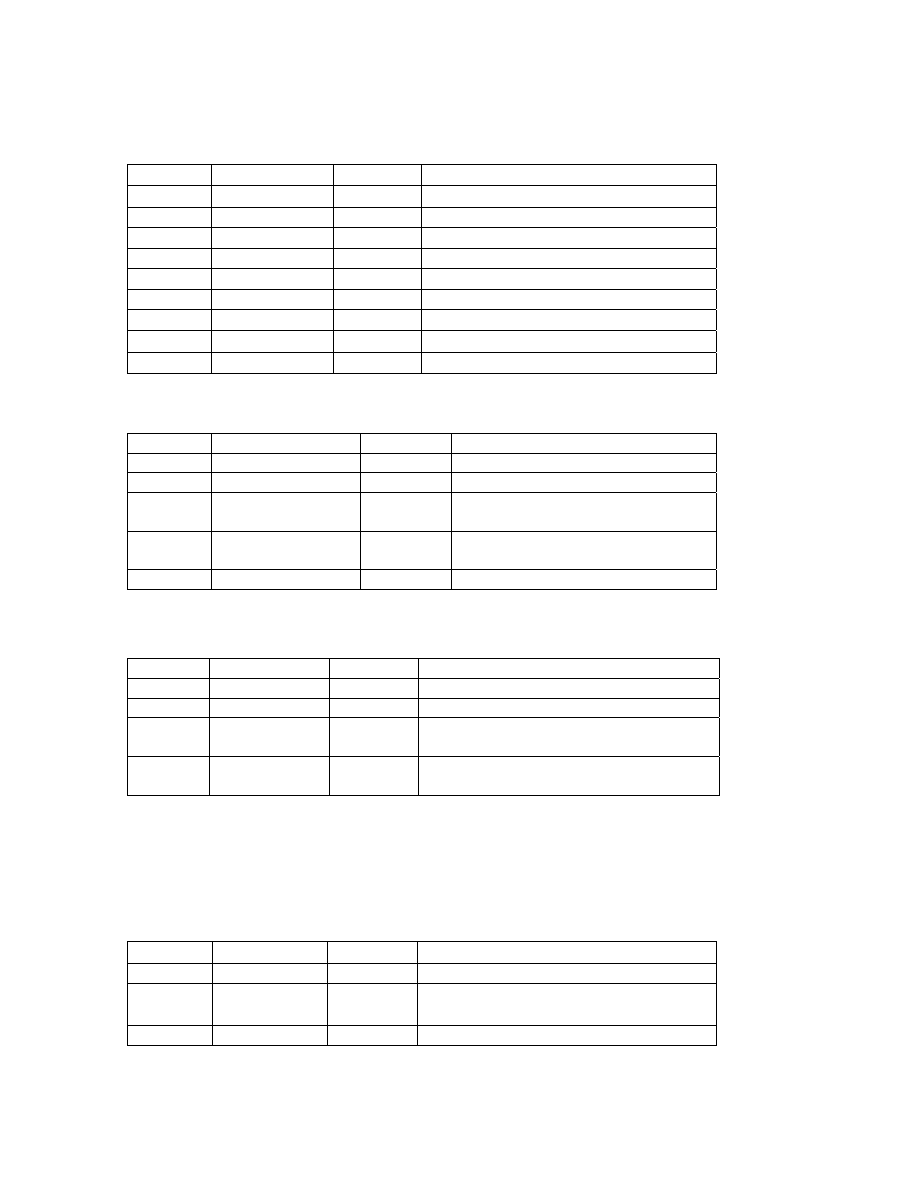
Table 1: Arithmetic Operators
Operator Name
Example Defined
*
Multiplication
x*y
Multiply x times y
/
Division
x/y
Divide x by y
%
Modulo
x%y
Provide the remainder of x divided by y
+
Addition
x+y
Add x and y
-
Subtraction
x-y
Subtract y from x
++
Increment
x++
Increment x after using it
--
Decrement
--x
Decrement x before using it
-
Negation
-x
Multiply x by –1
+
Unary Plus
+x
Show x is positive (not really needed)
Table 2: Data Access and Size Operators
Operator Name
Example Defined
[]
Array element
x[6]
Seventh element of array x
.
Member selection
PORTD.2
Bit 2 of Port D
->
Member selection
pStruct->x Member x of the structure pointed to
by pStruct
*
Indirection
*p
Contents of memory located at
address p
&
Address of
&x
Address of the variable x
Table 3: Miscellaneous Operators
Operator Name
Example Defined
()
Function
wait(10)
call wait with an argument of 10
(type)
Type cast
(double)x
x converted to a double
?:
Conditional
x?y:z
If x is not 0 evaluate y, otherwise evaluate
z
, Sequential
evaluation
x++,y++
Increment x first, then increment y
Relational and Logical Operators
Table 4: Logical and Relational Operators
Operator Name
Example Defined
>
Greater than
x>y
1 if x is greater than y, otherwise 0
>= Greater
than
or equal to
x>=y
1 if x is greater than or equal to y,
otherwise 0
<
Less than
x<y
1 if x is less than y, otherwise 0
5

Smiley’s Workshop 3: C Types, Operators and Expressions Part 1
<=
Less than or
equal to
x<=y
1 if x is less than or equal to y, otherwise
0
==
Equal to
x==y
1 if x equals y, otherwise 0
!=
Not equal to
x!=y
1 if x is not equal to y, otherwise 0
!
Logical NOT
!x
1 if x is 0, otherwise 0
&&
Logical AND
x&&y
0 if either x or y is 0, otherwise 1
||
Logical OR
x||y
0 if both x and y are 0, otherwise 1
Port Input and Output
We skimmed over a lot in Workshops 1 and 2 so that we could get some LEDs blinking.
Let’s now take a more detailed look at I/O ports.
AVRs are available with from 6 to 86 I/O pins (ATmega169 has 54 I/O pins). Most of
these pins are organized into ports, collections of pins that are setup and used with port
specific access and control registers. Many of the pins have more than one possible
function: they can be used to input or output digital logic data or they might be used for
detecting external interrupts or as input for clocks or for analog to digital conversions and
so on. The ATmega169 on the
These ports are like gates to an ancient city where the ancient electrons riding their very
tiny ancient donkeys enter and leave the city. Each port has three associated I/O memory
locations, port registers, which act as guards determining who shall pass.
Port Registers:
1. Data Direction Register - DDRx – Read/Write
2. Data Register – PORTx – Read/Write
3. Port Input Pins – PINx – Read Only
For example port A has: PORTA, DDRA, and PINA.
When used for general purpose I/O the port Data Direction Register must be set to tell the
micro whether a pin will be used for input or output. To use a pin for input, set the
associated DDRx bit to 0; to use it as output set it to 1. For example, to use the upper 4
bits of PORTD as inputs and the lower 4 bits as output, set the bits to 00001111, which,
as we’ve seen, in hex is 0x0F:
DDRD = 0x0F;
In this project we will set PORTB to input data from switches and PORTD to output +3V
to drive LEDs. We use the PINB register to read the switches from port B and write the
value to port D using the PORTD register.
6
Smiley’s Workshop 3: C Types, Operators and Expressions Part 1
Then we write an infinite loop that gets the switch data from port B using PINB and
equates it to PORTD that will light the LEDs.
Create a new AVRStudio project, PortIO.c, as discussed in Workshop 2 and enter the
following C code:
// PortIO.c
#include <avr/io.h>
int main (void)
{
// Set port data direction registers
DDRB = 0x00; // PORTB set to input
DDRD = 0xFF; // PORTD set to output
PORTB = 0xFF; // enable pull up on input port
while(1)
{
PORTD
=
PINB;
}
}
And as before, compile and download the hex file to the AVR Butterfly. Remember to
turn the Butterfly off and back on WITH THE JOYSTICK PRESSED TO THE
CENTER, then hold down the center joystick button while clicking on the ‘AVR prog…’
menu item in AVRStudio. And finally after the code downloads, remember to turn the
Butterfly off and back on then click the joystick to the upper position to start the
program.
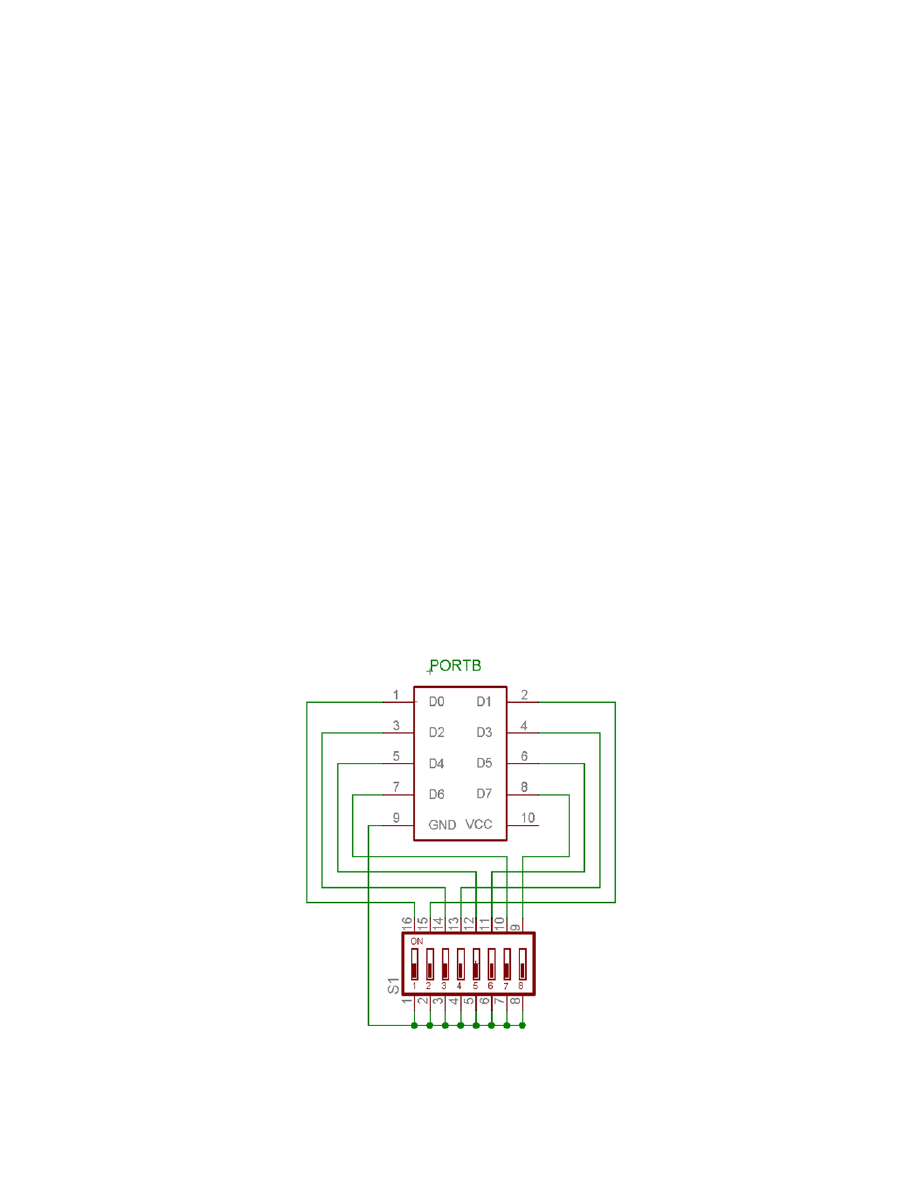
Figure 2: PORTB to 8-bit DIP Switch Schematic.
7
Smiley’s Workshop 3: C Types, Operators and Expressions Part 1
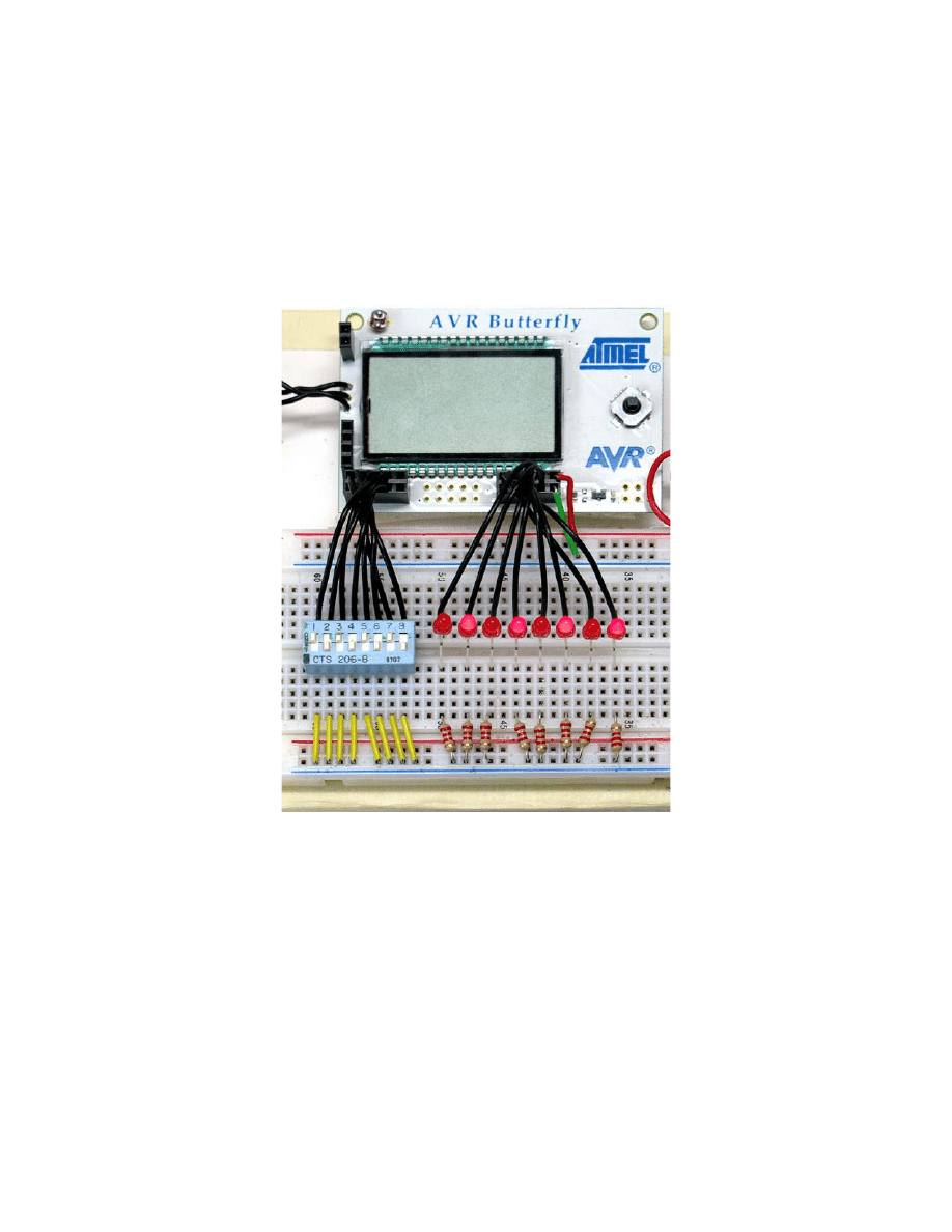
Using the LED wiring from the last project, add the switch as shown in Figures 2 and 3
and if everything goes as planned, the LEDs will display the state of the switches as
shown Figure 3. Now, if you are paying attention, you’ll say, ‘Hey wait a minute, these
switches and lights are reversed.’ And you’ll be wrong. PORTB pins are pulled up so
when nothing is on them they are high and the associated LED is high. The switches are
disconnected when off thus the pin remains high, and the switch pulls the pin to GND
when it is on, thus the associated LED turns off. Think about the logic behind this since
isn’t nearly the most confusing thing we’ll eventually see.
Figure 3: Port I/O
Well, that’s all for this month. Next month we’ll look at bitwise operators and do some
advanced CylonEye Optometry with sweep speed and polarity control.
8
Document Outline
Wyszukiwarka
Podobne podstrony:
08 PAW 5 6 Management Review Process Assessment Worksheet Rev 1 1 03
eim2 03 worksheet
eim1 03 worksheet
eim3 03 worksheet
CE Elementary module 03 web worksheet
Volkswagen Golf Variant 2007, Golf Variant 2010, Jetta 2005 Auxiliary heater Edition 03 2010 Work
03 Sejsmika04 plytkieid 4624 ppt
03 Odświeżanie pamięci DRAMid 4244 ppt
podrecznik 2 18 03 05
od Elwiry, prawo gospodarcze 03
Probl inter i kard 06'03
TT Sem III 14 03
03 skąd Państwo ma pieniądze podatki zus nfzid 4477 ppt
03 PODSTAWY GENETYKI
Wyklad 2 TM 07 03 09
więcej podobnych podstron