1 - 6
CCNP: Implementing Secure Converged Wide-area Networks v5.0 - Lab 5-8
Copyright
© 2007, Cisco Systems, Inc
Lab 5.8 Configuring NTP
Learning Objectives
• Configure a router as an NTP master server
• Configure an NTP server on a router
• Configure an NTP peer
• Implement
NTP
authentication
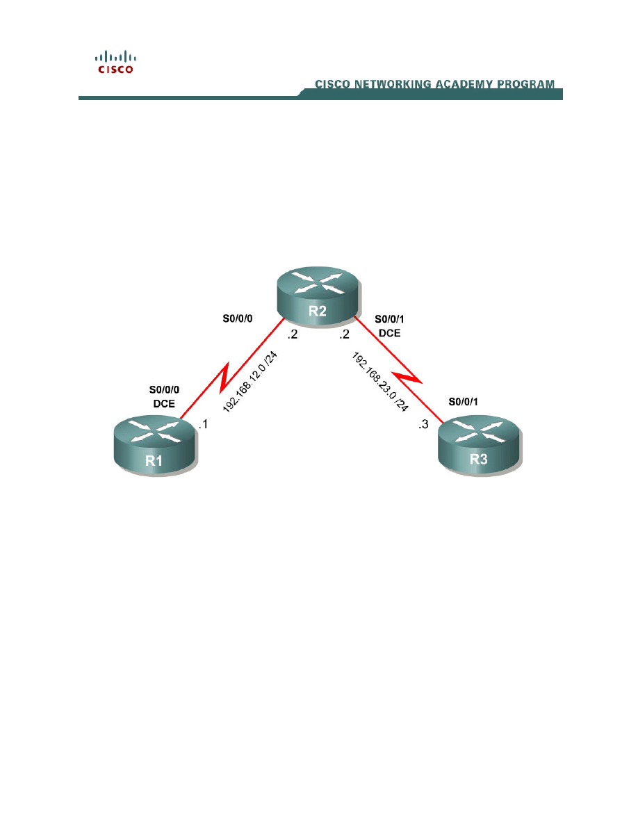
Topology Diagram
Scenario
In this lab, you will configure network time protocol (NTP) in a small topology.
NTP is essential in a large network, because it reduces administrative overhead
as well as allows for consistent times throughout the network for logging and
other time-related features, such as crypto certificate lifetimes.
Step 1: Configure the Physical Interfaces
Configure the loopback interfaces with the addresses shown in the topology
diagram. Also configure the serial interfaces shown in the diagram. Set the
clock rate on the appropriate interface, and issue the no shutdown command
on all serial connections. Verify that you have connectivity across the local
subnet using the ping command.
R1(config)# interface serial0/0/0
R1(config-if)# ip address 192.168.12.1 255.255.255.0
R1(config-if)# clockrate 64000
R1(config-if)# no shutdown

R2(config)# interface serial0/0/0
R2(config-if)# ip address 192.168.12.2 255.255.255.0
R2(config-if)# no shutdown
R2(config-if)# interface serial0/0/1
R2(config-if)# ip address 192.168.23.2 255.255.255.0
R2(config-if)# clockrate 64000
R2(config-if)# no shutdown
R3(config)# interface serial0/0/1
R3(config-if)# ip address 192.168.23.3 255.255.255.0
R3(config-if)# no shutdown
Step 2: Set Up the NTP Master
R1 is the master NTP server in this lab. All other routers learn their time from it,
either directly or indirectly. For this reason, you must first ensure that R1 has
the correct Coordinated Universal Time set.
Display the current time set on the router using the show clock command. To
set the time on the router, use the clock set time command.
R1# show clock
*07:20:19.267 UTC Mon Feb 12 2007
R1# clock set 07:20:30 feb 12 2007
R1#
*Feb 12 07:20:30.000: %SYS-6-CLOCKUPDATE: System clock has been updated from
07:20:39 UTC Mon Feb 12 2007 to 07:20:30 UTC Mon Feb 12 2007, configured from
console by console.
Configure R1 as the NTP master using the ntp master stratum command in
global configuration mode. The stratum number indicates the distance from the
original source. For this lab, use a stratum number of 5 on R1.
When a device learns the time from an NTP source, its stratum number
becomes one greater than its source’s stratum number.
R1(config)# ntp master 5
Step 3: Configure an NTP Client
R2 will become an NTP client of R1. To configure R2, use the global
configuration command ntp server hostname. Hostname can also be an IP
address.
R2(config)# ntp server 192.168.12.1
After a while, verify that R2 has made an association with R1 with the show ntp
association command. You can also use the more verbose version of the
command by adding the detail argument. It may take some time for the NTP
association to form.
R2# show ntp associations
address ref clock st when poll reach delay offset disp
2 - 6
CCNP: Implementing Secure Converged Wide-area Networks v5.0 - Lab 5-8
Copyright
© 2007, Cisco Systems, Inc

*~192.168.12.1 127.127.7.1 5 24 64 377 23.1 0.72 0.5
* master (synced), # master (unsynced), + selected, - candidate, ~ configured
R2# show ntp associations detail
192.168.12.1 configured, our_master, sane, valid, stratum 5
ref ID 127.127.7.1, time C97A9634.A5E51ED1 (07:31:00.648 UTC Mon Feb 12 2007)
our mode client, peer mode server, our poll intvl 64, peer poll intvl 64
root delay 0.00 msec, root disp 0.03, reach 377, sync dist 12.039
delay 23.09 msec, offset 0.7242 msec, dispersion 0.47
precision 2**18, version 3
org time C97A9643.CF0A3D1F (07:31:15.808 UTC Mon Feb 12 2007)
rcv time C97A9643.D1CFC661 (07:31:15.819 UTC Mon Feb 12 2007)
xmt time C97A9643.CBE4198B (07:31:15.796 UTC Mon Feb 12 2007)
filtdelay = 23.09 23.28 23.13 23.24 23.16 23.22 23.35 23.28
filtoffset = 0.72 0.44 0.07 0.06 0.04 0.06 0.05 -0.01
filterror = 0.02 0.99 1.97 1.98 2.00 2.01 2.03 2.04
Step 4: Configure NTP Peers with MD5 Authentication
In addition to the client-server model, NTP can also function with routers in a
peer relationship in which each router synchronizes against its peers. For this
scenario, R2 and R3 maintain a peering relationship.
Which security risks can either of these relationships pose?
To avoid a spoofing problem, configure MD5 authentication between the two
NTP peers, R2 and R3. Usually, when NTP authentication is configured in a
client-server model, the client authenticates the server, but not vice versa.
Thus, NTP authentication is source authentication; clients do not need to be
authenticated because they cannot manipulate the clock on the server.
However, because there is a peering relationship in which each peer may act
as a corrector to the other device, each device must be configured as an
authenticated NTP source. First, enable NTP authentication with the ntp
authenticate command in global configuration mode. Next, add an NTP
authentication key to the router with the ntp authentication-key number md5
key-string command. Apply a key number of 1 for the key “cisco”. Finally, apply
the authentication configuration by specifying NTP key number 1 as a trusted
NTP source key with the ntp trusted-key number command.
R2(config)# ntp authenticate
R2(config)# ntp authentication-key 1 md5 cisco
R2(config)# ntp trusted-key 1
R3(config)# ntp authenticate
R3(config)# ntp authentication-key 1 md5 cisco
R3(config)# ntp trusted-key 1
3 - 6
CCNP: Implementing Secure Converged Wide-area Networks v5.0 - Lab 5-8
Copyright
© 2007, Cisco Systems, Inc

Configure the NTP peer on R3. NTP peers have a passive side and an active
side. You only have to configure the active side, in this case R3. R2 is listening
on the NTP port and will form a peer relationship through this. Do not configure
peers on both sides of the peer relationship, or it will not work. One of the
devices in the peer relationship must be in active mode and the other device
must be in passive mode for proper peer synchronization to occur.
R3(config)# ntp peer 192.168.23.2
It may take a few moments for the relationship to establish. On each of the
three routers, verify NTP status and associations using the show ntp status,
show ntp associations, and show ntp associations detail commands. Notice
how the stratum level increases at each hop. Verify that their clocks are indeed
synchronized with the show clock command.
R1# show ntp status
Clock is synchronized, stratum 5, reference is 127.127.7.1
nominal freq is 250.0000 Hz, actual freq is 250.0000 Hz, precision is 2**18
reference time is C97A9B74.A5DF14AD (07:53:24.647 UTC Mon Feb 12 2007)
clock offset is 0.0000 msec, root delay is 0.00 msec
root dispersion is 0.02 msec, peer dispersion is 0.02 msec
R1# show ntp associations
address ref clock st when poll reach delay offset disp
*~127.127.7.1 127.127.7.1 4 55 64 377 0.0 0.00 0.0
* master (synced), # master (unsynced), + selected, - candidate, ~ configured
R1# show ntp associations detail
127.127.7.1 configured, our_master, sane, valid, stratum 4
ref ID 127.127.7.1, time C97A9B74.A5DF14AD (07:53:24.647 UTC Mon Feb 12 2007)
our mode active, peer mode passive, our poll intvl 64, peer poll intvl 64
root delay 0.00 msec, root disp 0.00, reach 377, sync dist 0.015
delay 0.00 msec, offset 0.0000 msec, dispersion 0.02
precision 2**18, version 3
org time C97A9B74.A5DF14AD (07:53:24.647 UTC Mon Feb 12 2007)
rcv time C97A9B74.A5DF14AD (07:53:24.647 UTC Mon Feb 12 2007)
xmt time C97A9B74.A5DE90AF (07:53:24.647 UTC Mon Feb 12 2007)
filtdelay = 0.00 0.00 0.00 0.00 0.00 0.00 0.00 0.00
filtoffset = 0.00 0.00 0.00 0.00 0.00 0.00 0.00 0.00
filterror = 0.02 0.99 1.97 2.94 3.92 4.90 5.87 6.85
Reference clock status: Running normally
Timecode:
R2# show ntp status
Clock is synchronized, stratum 6, reference is 192.168.12.1
nominal freq is 250.0000 Hz, actual freq is 249.9998 Hz, precision is 2**18
reference time is C97A9BC3.D3820015 (07:54:43.826 UTC Mon Feb 12 2007)
clock offset is 1.9937 msec, root delay is 23.32 msec
root dispersion is 2.04 msec, peer dispersion is 0.03 msec
R2# show ntp associations
address ref clock st when poll reach delay offset disp
*~192.168.12.1 127.127.7.1 5 14 64 377 23.3 1.99 0.0
* master (synced), # master (unsynced), + selected, - candidate, ~ configured
R2# show ntp associations detail
192.168.12.1 configured, our_master, sane, valid, stratum 5
4 - 6
CCNP: Implementing Secure Converged Wide-area Networks v5.0 - Lab 5-8
Copyright
© 2007, Cisco Systems, Inc

ref ID 127.127.7.1, time C97A9BB4.A5DEE42C (07:54:28.647 UTC Mon Feb 12 2007)
our mode client, peer mode server, our poll intvl 64, peer poll intvl 64
root delay 0.00 msec, root disp 0.03, reach 377, sync dist 11.902
delay 23.32 msec, offset 1.9937 msec, dispersion 0.03
precision 2**18, version 3
org time C97A9BC3.D1082A4F (07:54:43.816 UTC Mon Feb 12 2007)
rcv time C97A9BC3.D3820015 (07:54:43.826 UTC Mon Feb 12 2007)
xmt time C97A9BC3.CD87599E (07:54:43.802 UTC Mon Feb 12 2007)
filtdelay = 23.32 23.38 23.21 23.25 23.07 23.18 23.25 23.22
filtoffset = 1.99 1.95 1.99 1.98 1.93 1.98 1.96 1.94
filterror = 0.02 0.99 1.97 2.94 3.92 4.90 5.87 6.85
R3# show ntp status
Clock is synchronized, stratum 7, reference is 192.168.23.2
nominal freq is 250.0000 Hz, actual freq is 250.0000 Hz, precision is 2**18
reference time is C97A9BCF.B82D5269 (07:54:55.719 UTC Mon Feb 12 2007)
clock offset is -1.3696 msec, root delay is 25.59 msec
root dispersion is 3.92 msec, peer dispersion is 0.49 msec
R3# show ntp associations
address ref clock st when poll reach delay offset disp
*~192.168.23.2 192.168.12.1 6 27 64 377 2.3 -1.37 0.5
* master (synced), # master (unsynced), + selected, - candidate, ~ configured
R3# show ntp associations detail
192.168.23.2 configured, our_master, sane, valid, stratum 6
ref ID 192.168.12.1, time C97A9BC3.D3820015 (07:54:43.826 UTC Mon Feb 12 2007)
our mode active, peer mode passive, our poll intvl 64, peer poll intvl 64
root delay 23.32 msec, root disp 2.06, reach 377, sync dist 15.335
delay 2.27 msec, offset -1.3696 msec, dispersion 0.49
precision 2**18, version 3
org time C97A9BCF.B788986A (07:54:55.716 UTC Mon Feb 12 2007)
rcv time C97A9BCF.B82D5269 (07:54:55.719 UTC Mon Feb 12 2007)
xmt time C97A9BCF.B7903BF8 (07:54:55.717 UTC Mon Feb 12 2007)
filtdelay = 2.27 2.26 2.29 2.30 2.29 2.27 2.29 2.26
filtoffset = -1.37 -1.16 -0.90 -0.49 -0.10 -0.10 -0.09 -0.08
filterror = 0.02 0.99 1.97 2.94 3.92 3.94 3.95 3.97
Why would it be good to have routers peering equally rather than a client-server
relationship?
Final Configuration
R1# show run
hostname R1
!
interface Serial0/0/0
ip address 192.168.12.1 255.255.255.0
clock rate 64000
no shutdown
!
ntp master 5
5 - 6
CCNP: Implementing Secure Converged Wide-area Networks v5.0 - Lab 5-8
Copyright
© 2007, Cisco Systems, Inc

end
R2# show run
hostname R2
!
interface Serial0/0/0
ip address 192.168.12.2 255.255.255.0
no shutdown
!
interface Serial0/0/1
ip address 192.168.23.2 255.255.255.0
clockrate 64000
no shutdown
!
ntp authentication-key 1 md5 01100F175804 7
ntp authenticate
ntp trusted-key 1
ntp server 192.168.12.1
end
R3# show run
hostname R3
!
interface Serial0/0/1
ip address 192.168.23.3 255.255.255.0
no shutdown
!
ntp authentication-key 1 md5 00071A150754 7
ntp authenticate
ntp trusted-key 1
ntp peer 192.168.23.2
end
6 - 6
CCNP: Implementing Secure Converged Wide-area Networks v5.0 - Lab 5-8
Copyright
© 2007, Cisco Systems, Inc
Wyszukiwarka
Podobne podstrony:
CCNP2 lab 4 1 en
CCNP2 lab 3 5 en
CCNP2 lab 5 5 en
CCNP2 lab 5 4 en
CCNP2 lab 3 6 en
CCNP2 lab 3 9 en
CCNP2 lab 5 7 en
CCNP2 lab 3 4 en
CCNP2 lab 4 2 en
CCNP2 lab 3 2 en
CCNP2 lab 5 1 en
CCNP2 lab 6 1 en
CCNP2 lab 6 3 en
CCNP2 lab 6 4 en
CCNP2 lab 5 2 en
CCNP2 lab 3 8 en
CCNP2 lab 6 2 en
CCNP2 lab 3 7 en
CCNP2 lab 5 3 en
więcej podobnych podstron