1 - 11
CCNP: Implementing Secure Converged Wide-area Networks v5.0 - Lab 3-8
Copyright
© 2007, Cisco Systems, Inc
Lab 3.8 Configuring IPsec VTIs
Learning Objectives
• Configure EIGRP on a router
• Configure an IPsec Virtual Tunnel Interface
• Configure the VTI to be used for backup purposes only
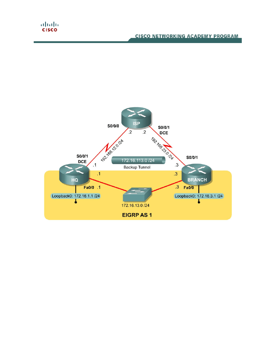
Topology Diagram
Scenario
The headquarters and branch office routers of International Travel Agency are
connected over a leased line, which they receive as an Ethernet connection.
They also both have slower, serial links connecting them to the Internet. This
lab will cover configuring an IPsec Virtual Tunnel Interface, or VTI, to be used
as a backup connection, running over the public internet.
If you have previously completed Lab 3.7 in which you created secure GRE
tunnels, the results are similar; however, this newer method is the preferred
method. If you are running an older IOS release, this feature may not be
supported. It is highly recommended that you have previously configured GRE
tunnels and IPsec VPNs to understand the commands being used in this lab.

Step 1: Configure Addressing
Configure the loopback interfaces with the addresses shown in the diagram.
Also configure the serial interfaces shown in the diagram. Set the clock rates on
the appropriate interfaces and issue the no shutdown command on all serial
connections. Verify that you have connectivity across the local subnet with the
ping command. Do not set up the tunnel interface until Step 7.
HQ# configure terminal
HQ(config)# interface loopback 0
HQ(config-if)# ip address 172.16.1.1 255.255.255.0
HQ(config-if)# interface fastethernet 0/0
HQ(config-if)# ip address 172.16.13.1 255.255.255.0
HQ(config-if)# no shutdown
HQ(config-if)# interface serial 0/0/0
HQ(config-if)# ip address 192.168.12.1 255.255.255.0
HQ(config-if)# clockrate 64000
HQ(config-if)# no shutdown
ISP# configure terminal
ISP(config-if)# interface serial 0/0/0
ISP(config-if)# ip address 192.168.12.2 255.255.255.0
ISP(config-if)# no shutdown
ISP(config-if)# interface serial 0/0/1
ISP(config-if)# ip address 192.168.23.2 255.255.255.0
ISP(config-if)# clockrate 64000
ISP(config-if)# no shutdown
BRANCH# configure terminal
BRANCH(config)# interface loopback 0
BRANCH(config-if)# ip address 172.16.3.1 255.255.255.0
BRANCH(config-if)# interface fastethernet 0/0
BRANCH(config-if)# ip address 172.16.13.3 255.255.255.0
BRANCH(config-if)# no shutdown
BRANCH(config-if)# interface serial 0/0/1
BRANCH(config-if)# ip address 192.168.23.3 255.255.255.0
BRANCH(config-if)# no shutdown
Step 2: Configure EIGRP AS 1
Configure EIGRP for AS1 on HQ and BRANCH. Add the whole major network
172.16.0.0 and disable automatic summarization. ISP will not participate in this
routing process.
HQ(config)# router eigrp 1
HQ(config-router)# no auto-summary
HQ(config-router)# network 172.16.0.0
BRANCH(config)# router eigrp 1
BRANCH(config-router)# no auto-summary
BRANCH(config-router)# network 172.16.0.0
EIGRP neighbor adjacencies should form. If not, troubleshoot by checking your
interface configuration, EIGRP configuration, and physical connectivity.
2 - 11
CCNP: Implementing Secure Converged Wide-area Networks v5.0 - Lab 3-8
Copyright
© 2007, Cisco Systems, Inc

Step 3: Configure Static Routing
On the HQ and BRANCH routers, add a static default route pointing towards
ISP through the serial interfaces. This will simulate a connection to the internet.
Remember that this route will not be preferred over routes learned via
Enhanced Interior Gateway Routing Protocol (EIGRP), because the EIGRP
routes will be more specific and therefore preferred. We also do not need to
configure any static routes on ISP because it has connected routes to route
between the 192.168.X.0/24 networks HQ and BRANCH.
HQ(config)# ip route 0.0.0.0 0.0.0.0 192.168.12.2
BRANCH(config)# ip route 0.0.0.0 0.0.0.0 192.168.23.2
Now everything is in place for configuring the backup tunnel to run over the
Internet. Before starting, be sure that both HQ and BRANCH can successfully
ping each other’s Internet-facing interface (which should be routed via ISP), and
the other’s loopback interface. Compare the output of the show ip route
command to the following output.
HQ# ping 192.168.23.3
Type escape sequence to abort.
Sending 5, 100-byte ICMP Echos to 192.168.23.3, timeout is 2 seconds:
!!!!!
Success rate is 100 percent (5/5), round-trip min/avg/max = 56/56/56 ms
HQ# ping 172.16.3.1
Type escape sequence to abort.
Sending 5, 100-byte ICMP Echos to 172.16.3.1, timeout is 2 seconds:
!!!!!
Success rate is 100 percent (5/5), round-trip min/avg/max = 1/2/4 ms
HQ# show ip route
Codes: C - connected, S - static, R - RIP, M - mobile, B - BGP
D - EIGRP, EX - EIGRP external, O - OSPF, IA - OSPF inter area
N1 - OSPF NSSA external type 1, N2 - OSPF NSSA external type 2
E1 - OSPF external type 1, E2 - OSPF external type 2
i - IS-IS, su - IS-IS summary, L1 - IS-IS level-1, L2 - IS-IS level-2
ia - IS-IS inter area, * - candidate default, U - per-user static route
o - ODR, P - periodic downloaded static route
Gateway of last resort is 192.168.12.2 to network 0.0.0.0
C 192.168.12.0/24 is directly connected, Serial0/0/0
172.16.0.0/24 is subnetted, 3 subnets
C 172.16.13.0 is directly connected, FastEthernet0/0
C 172.16.1.0 is directly connected, Loopback0
D 172.16.3.0 [90/156160] via 172.16.13.3, 00:01:56, FastEthernet0/0
S* 0.0.0.0/0 [1/0] via 192.168.12.2
BRANCH# ping 192.168.12.1
Type escape sequence to abort.
Sending 5, 100-byte ICMP Echos to 192.168.12.1, timeout is 2 seconds:
!!!!!
Success rate is 100 percent (5/5), round-trip min/avg/max = 56/56/56 ms
3 - 11
CCNP: Implementing Secure Converged Wide-area Networks v5.0 - Lab 3-8
Copyright
© 2007, Cisco Systems, Inc

BRANCH# ping 172.16.1.1
Type escape sequence to abort.
Sending 5, 100-byte ICMP Echos to 172.16.1.1, timeout is 2 seconds:
!!!!!
Success rate is 100 percent (5/5), round-trip min/avg/max = 1/1/4 ms
BRANCH# show ip route
Codes: C - connected, S - static, R - RIP, M - mobile, B - BGP
D - EIGRP, EX - EIGRP external, O - OSPF, IA - OSPF inter area
N1 - OSPF NSSA external type 1, N2 - OSPF NSSA external type 2
E1 - OSPF external type 1, E2 - OSPF external type 2
i - IS-IS, su - IS-IS summary, L1 - IS-IS level-1, L2 - IS-IS level-2
ia - IS-IS inter area, * - candidate default, U - per-user static route
o - ODR, P - periodic downloaded static route
Gateway of last resort is 192.168.23.2 to network 0.0.0.0
172.16.0.0/24 is subnetted, 3 subnets
C 172.16.13.0 is directly connected, FastEthernet0/0
D 172.16.1.0 [90/156160] via 172.16.13.1, 00:02:32, FastEthernet0/0
C 172.16.3.0 is directly connected, Loopback0
C 192.168.23.0/24 is directly connected, Serial0/0/1
S* 0.0.0.0/0 [1/0] via 192.168.23.2
Step 4: Create IKE Policies and Peers
Since you will be using Internet Security Association and Key Management
Protocol (ISAKMP) with IPsec, configure Internet Key Exchange (IKE) policies
and IKE peers on both tunnel endpoints. Create an IKE policy as shown in the
following output. If your IOS image doesn’t support all of the settings, configure
what you can. Just make sure your VPN settings match on both ends of the
connection.
HQ(config)# crypto isakmp policy 10
HQ(config-isakmp)# authentication pre-share
HQ(config-isakmp)# encryption aes 256
HQ(config-isakmp)# hash sha
HQ(config-isakmp)# group 5
HQ(config-isakmp)# lifetime 3600
BRANCH(config)# crypto isakmp policy 10
BRANCH(config-isakmp)# authentication pre-share
BRANCH(config-isakmp)# encryption aes 256
BRANCH(config-isakmp)# hash sha
BRANCH(config-isakmp)# group 5
BRANCH(config-isakmp)# lifetime 3600
Which of the options ensures data confidentiality in the tunnel?
Which of the options ensures data integrity in the tunnel?
4 - 11
CCNP: Implementing Secure Converged Wide-area Networks v5.0 - Lab 3-8
Copyright
© 2007, Cisco Systems, Inc

Which of the options controls the strength of keying information during the
ISAKMP exchange?
Now, configure each peer using the key “cisco” for ISAKMP.
HQ(config)# crypto isakmp key cisco address 192.168.23.3
BRANCH(config)# crypto isakmp key cisco address 192.168.12.1
Step 5: Create IPsec Transform Sets
On both endpoint routers, create an IPsec transform set using the settings that
follow. An IPsec profile is a set of parameters used to negotiate an IPsec VPN
tunnel between two endpoints, including data encapsulation, authentication,
and integrity.
HQ(config)# crypto ipsec transform-set mytrans esp-aes 256 esp-sha-hmac ah-
sha-hmac
HQ(cfg-crypto-trans)# exit
HQ(config)#
BRANCH(config)# crypto ipsec transform-set mytrans esp-aes 256 esp-sha-hmac
ah-sha-hmac
BRANCH(cfg-crypto-trans)# exit
BRANCH(config)#
If your routers do not support these settings, use whichever settings you can.
Just keep it consistent on both routers.
Step 6: Create an IPsec Profile
Now that you have created the transform set, create an IPsec profile. An IPsec
profile is similar to a crypto map, in that it binds the set of independent
parameters and associations negotiated in IKE Phase I with the transform sets
for Phase II. It also creates a structure that can, like a crypto map, be applied to
an interface. However, an IPsec profile differs from a crypto map in that there is
no match clause, only set statements, because it is applied to an interface. All
traffic sent into or out of the tunnel interface will be encrypted.
5 - 11
CCNP: Implementing Secure Converged Wide-area Networks v5.0 - Lab 3-8
Copyright
© 2007, Cisco Systems, Inc

To begin configuring an IPsec profile, use the global configuration command
crypto ipsec profile name. In this configuration, use “myprof” as the profile
name.
HQ(config)# crypto ipsec profile myprof
In the IPsec profile configuration submode, type set ? to find out various
attributes you can set with an IPsec profile.
HQ(ipsec-profile)# set ?
identity Identity restriction.
isakmp-profile Specify isakmp Profile
pfs Specify pfs settings
security-association Security association parameters
transform-set Specify list of transform sets in priority order
As you can see, the set parameters are very similar to the parameters you can
set in a crypto map. In this case, we will only set the transform set to the
transform set we configured earlier. Apply the same configuration to BRANCH.
HQ(ipsec-profile)# set transform-set mytrans
BRANCH(config)# crypto ipsec profile myprof
BRANCH(ipsec-profile)# set transform-set mytrans
Step 7: Create the IPsec VTI
HQ and BRANCH will need to have a tunnel interface on them, which will have
the standard tunnel IP address and source and destination. The source and
destination should be the serial connections to ISP. In addition to this, you
should change the mode of the tunnel using the interface level command
tunnel mode mode, and in this case, the mode will be ipsec with IPv4. To apply
the IPsec profile created earlier, use the interface level command tunnel
protection ipsec profile name.
HQ(config)# interface tunnel 0
HQ(config-if)# ip address 172.16.113.1 255.255.255.0
HQ(config-if)# tunnel source serial 0/0/0
HQ(config-if)# tunnel destination 192.168.23.3
HQ(config-if)# tunnel mode ipsec ipv4
HQ(config-if)# tunnel protection ipsec profile myprof
BRANCH(config)# interface tunnel 0
BRANCH(config-if)# ip address 172.16.113.3 255.255.255.0
BRANCH(config-if)# tunnel source serial 0/0/1
BRANCH(config-if)# tunnel destination 192.168.12.1
BRANCH(config-if)# tunnel mode ipsec ipv4
BRANCH(config-if)# tunnel protection ipsec profile myprof
If the endpoints of the tunnel are the serial interfaces facing ISP, then when will
routed traffic to the private 172.16.0.0/24 network be sent through the tunnel?
6 - 11
CCNP: Implementing Secure Converged Wide-area Networks v5.0 - Lab 3-8
Copyright
© 2007, Cisco Systems, Inc

Use the show crypto ipsec sa command to verify that the packet counters are
incrementing with EIGRP hello packets across the tunnel. Also verify that the
EIGRP neighbor adjacency is up with the show ip eigrp neighbors command.
HQ# show crypto ipsec sa
interface: Tunnel0
Crypto map tag: Tunnel0-head-0, local addr 192.168.12.1
protected vrf: (none)
local ident (addr/mask/prot/port): (0.0.0.0/0.0.0.0/0/0)
remote ident (addr/mask/prot/port): (0.0.0.0/0.0.0.0/0/0)
current_peer 192.168.23.3 port 500
PERMIT, flags={origin_is_acl,}
#pkts encaps: 14, #pkts encrypt: 14, #pkts digest: 14
#pkts decaps: 16, #pkts decrypt: 16, #pkts verify: 16
<OUTPUT OMITTED>
HQ# show crypto ipsec sa
interface: Tunnel0
Crypto map tag: Tunnel0-head-0, local addr 192.168.12.1
protected vrf: (none)
local ident (addr/mask/prot/port): (0.0.0.0/0.0.0.0/0/0)
remote ident (addr/mask/prot/port): (0.0.0.0/0.0.0.0/0/0)
current_peer 192.168.23.3 port 500
PERMIT, flags={origin_is_acl,}
#pkts encaps: 15, #pkts encrypt: 15, #pkts digest: 15
#pkts decaps: 17, #pkts decrypt: 17, #pkts verify: 17
<OUTPUT OMITTED>
HQ# show ip eigrp neighbors
IP-EIGRP neighbors for process 1
H Address Interface Hold Uptime SRTT RTO Q Seq
(sec) (ms) Cnt Num
1 172.16.113.3 Tu0 11 00:03:40 118 5000 0 15
0 172.16.13.3 Fa0/0 10 01:04:20 1 200 0 13
BRANCH# show crypto ipsec sa
interface: Tunnel0
Crypto map tag: Tunnel0-head-0, local addr 192.168.23.3
protected vrf: (none)
local ident (addr/mask/prot/port): (0.0.0.0/0.0.0.0/0/0)
remote ident (addr/mask/prot/port): (0.0.0.0/0.0.0.0/0/0)
current_peer 192.168.12.1 port 500
PERMIT, flags={origin_is_acl,}
#pkts encaps: 40, #pkts encrypt: 40, #pkts digest: 40
#pkts decaps: 39, #pkts decrypt: 39, #pkts verify: 39
<OUTPUT OMITTED>
BRANCH# show crypto ipsec sa
interface: Tunnel0
Crypto map tag: Tunnel0-head-0, local addr 192.168.23.3
protected vrf: (none)
7 - 11
CCNP: Implementing Secure Converged Wide-area Networks v5.0 - Lab 3-8
Copyright
© 2007, Cisco Systems, Inc

local ident (addr/mask/prot/port): (0.0.0.0/0.0.0.0/0/0)
remote ident (addr/mask/prot/port): (0.0.0.0/0.0.0.0/0/0)
current_peer 192.168.12.1 port 500
PERMIT, flags={origin_is_acl,}
#pkts encaps: 41, #pkts encrypt: 41, #pkts digest: 41
#pkts decaps: 41, #pkts decrypt: 41, #pkts verify: 41
<OUTPUT OMITTED>
BRANCH# show ip eigrp neighbors
IP-EIGRP neighbors for process 1
H Address Interface Hold Uptime SRTT RTO Q Seq
(sec) (ms) Cnt Num
1 172.16.113.1 Tu0 11 00:03:48 118 5000 0 12
0 172.16.13.1 Fa0/0 12 01:04:28 333 1998 0 11
Step 8: Verify Proper EIGRP Behavior
On HQ, issue a show ip route command and make sure that the preferred
route to the BRANCH loopback is through the leased line (FastEthernet0/0).
HQ# show ip route
Codes: C - connected, S - static, R - RIP, M - mobile, B - BGP
D - EIGRP, EX - EIGRP external, O - OSPF, IA - OSPF inter area
N1 - OSPF NSSA external type 1, N2 - OSPF NSSA external type 2
E1 - OSPF external type 1, E2 - OSPF external type 2
i - IS-IS, su - IS-IS summary, L1 - IS-IS level-1, L2 - IS-IS level-2
ia - IS-IS inter area, * - candidate default, U - per-user static route
o - ODR, P - periodic downloaded static route
Gateway of last resort is 192.168.12.2 to network 0.0.0.0
C 192.168.12.0/24 is directly connected, Serial0/0/0
172.16.0.0/24 is subnetted, 4 subnets
C 172.16.13.0 is directly connected, FastEthernet0/0
C 172.16.1.0 is directly connected, Loopback0
D 172.16.3.0 [90/156160] via 172.16.13.3, 00:13:29, FastEthernet0/0
C 172.16.113.0 is directly connected, Tunnel0
S* 0.0.0.0/0 [1/0] via 192.168.12.2
Now, shut down the leased line connection on BRANCH.
BRANCH(config)# interface fastethernet 0/0
BRANCH(config-if)# shutdown
On HQ, try issuing a show ip route command again after the neighbor
adjacency expires.
*Jan 23 02:14:17.931: %DUAL-5-NBRCHANGE: IP-EIGRP(0) 1: Neighbor 172.16.13.3
(FastEthernet0/0) is down: holding time expired
HQ# show ip route
Codes: C - connected, S - static, R - RIP, M - mobile, B - BGP
D - EIGRP, EX - EIGRP external, O - OSPF, IA - OSPF inter area
N1 - OSPF NSSA external type 1, N2 - OSPF NSSA external type 2
E1 - OSPF external type 1, E2 - OSPF external type 2
i - IS-IS, su - IS-IS summary, L1 - IS-IS level-1, L2 - IS-IS level-2
ia - IS-IS inter area, * - candidate default, U - per-user static route
o - ODR, P - periodic downloaded static route
Gateway of last resort is 192.168.12.2 to network 0.0.0.0
8 - 11
CCNP: Implementing Secure Converged Wide-area Networks v5.0 - Lab 3-8
Copyright
© 2007, Cisco Systems, Inc

C 192.168.12.0/24 is directly connected, Serial0/0/0
172.16.0.0/24 is subnetted, 4 subnets
C 172.16.13.0 is directly connected, FastEthernet0/0
C 172.16.1.0 is directly connected, Loopback0
D 172.16.3.0 [90/297372416] via 172.16.113.3, 00:00:44, Tunnel0
C 172.16.113.0 is directly connected, Tunnel0
S* 0.0.0.0/0 [1/0] via 192.168.12.2
Shutting down the Fast Ethernet interface on BRANCH simulates the leased
line being disconnected. As you can see, the network reconverges to use the
protected tunnel through the ISP router. Perform another traceroute to verify
that the path now goes through the tunnel.
What happens to IP traffic passing through the tunnel?
Of course, this transport path is slower than the leased line, and is only
preferred as a temporary backup, not a permanent solution. Open the
FastEthernet0/0 interface that you shutdown earlier, and verify on HQ that the
transit path is back to the way it was.
BRANCH(config)# interface fastethernet 0/0
BRANCH(config-if)# no shutdown
*Jan 23 02:18:56.959: %DUAL-5-NBRCHANGE: IP-EIGRP(0) 1: Neighbor 172.16.13.3
(FastEthernet0/0) is up: new adjacency
HQ# show ip route
Codes: C - connected, S - static, R - RIP, M - mobile, B - BGP
D - EIGRP, EX - EIGRP external, O - OSPF, IA - OSPF inter area
N1 - OSPF NSSA external type 1, N2 - OSPF NSSA external type 2
E1 - OSPF external type 1, E2 - OSPF external type 2
i - IS-IS, su - IS-IS summary, L1 - IS-IS level-1, L2 - IS-IS level-2
ia - IS-IS inter area, * - candidate default, U - per-user static route
o - ODR, P - periodic downloaded static route
Gateway of last resort is 192.168.12.2 to network 0.0.0.0
C 192.168.12.0/24 is directly connected, Serial0/0/0
172.16.0.0/24 is subnetted, 4 subnets
C 172.16.13.0 is directly connected, FastEthernet0/0
C 172.16.1.0 is directly connected, Loopback0
D 172.16.3.0 [90/156160] via 172.16.13.3, 00:00:29, FastEthernet0/0
C 172.16.113.0 is directly connected, Tunnel0
S* 0.0.0.0/0 [1/0] via 192.168.12.2
You can understand why EIGRP prefers the path through the Fast Ethernet
network if you look at the default bandwidth and delay on the Fast Ethernet and
Tunnel interfaces with the show interfaces interface-type interface-number
command. Remember that EIGRP will prefer the path with the minimum
9 - 11
CCNP: Implementing Secure Converged Wide-area Networks v5.0 - Lab 3-8
Copyright
© 2007, Cisco Systems, Inc

composite metric of minimum path bandwidth and lowest total delay. As the
output shows, there are radical differences in these attributes between Fast
Ethernet and Tunnel interfaces. If you needed to change these to make the
routes preferred in a certain way, you could modify the attributes with the
interface level commands bandwidth bandwidth and delay delay, although
these commands are outside the scope of this lab.
HQ# show interfaces fastethernet 0/0
FastEthernet0/0 is up, line protocol is up
Hardware is MV96340 Ethernet, address is 0019.0623.4380 (bia 0019.0623.4380)
Internet address is 172.16.13.1/24
MTU 1500 bytes, BW 100000 Kbit, DLY 100 usec,
HQ# show interfaces tunnel 0
Tunnel0 is up, line protocol is up
Hardware is Tunnel
Internet address is 172.16.113.1/24
MTU 1514 bytes, BW 9 Kbit, DLY 500000 usec,
Final Configurations
HQ# show run
!
hostname HQ
!
crypto isakmp policy 10
encr aes 256
authentication pre-share
group 5
lifetime 3600
crypto isakmp key cisco address 192.168.23.3
!
crypto ipsec transform-set mytrans ah-sha-hmac esp-aes 256 esp-sha-hmac
!
crypto ipsec profile myprof
set transform-set mytrans
!
interface Tunnel0
ip address 172.16.113.1 255.255.255.0
tunnel source Serial0/0/0
tunnel destination 192.168.23.3
tunnel mode ipsec ipv4
tunnel protection ipsec profile myprof
!
interface Loopback0
ip address 172.16.1.1 255.255.255.0
!
interface FastEthernet0/0
ip address 172.16.13.1 255.255.255.0
no shutdown
!
interface Serial0/0/0
ip address 192.168.12.1 255.255.255.0
clock rate 64000
no shutdown
!
router eigrp 1
network 172.16.0.0
no auto-summary
!
ip route 0.0.0.0 0.0.0.0 192.168.12.2
10 - 11
CCNP: Implementing Secure Converged Wide-area Networks v5.0 - Lab 3-8
Copyright
© 2007, Cisco Systems, Inc

!
end
ISP# show run
!
hostname ISP
!
interface Serial0/0/0
ip address 192.168.12.2 255.255.255.0
no shutdown
!
interface Serial0/0/1
ip address 192.168.23.2 255.255.255.0
clock rate 64000
no shutdown
!
end
BRANCH# show run
hostname BRANCH
!
crypto isakmp policy 10
encr aes 256
authentication pre-share
group 5
lifetime 3600
crypto isakmp key cisco address 192.168.12.1
!
crypto ipsec transform-set mytrans ah-sha-hmac esp-aes 256 esp-sha-hmac
!
crypto ipsec profile myprof
set transform-set mytrans
!
interface Loopback0
ip address 172.16.3.1 255.255.255.0
!
interface Tunnel0
ip address 172.16.113.3 255.255.255.0
tunnel source Serial0/0/1
tunnel destination 192.168.12.1
tunnel mode ipsec ipv4
tunnel protection ipsec profile myprof
!
interface FastEthernet0/0
ip address 172.16.13.3 255.255.255.0
no shutdown
!
interface Serial0/0/1
ip address 192.168.23.3 255.255.255.0
no shutdown
!
router eigrp 1
network 172.16.0.0
no auto-summary
!
ip route 0.0.0.0 0.0.0.0 192.168.23.2
!
end
11 - 11
CCNP: Implementing Secure Converged Wide-area Networks v5.0 - Lab 3-8
Copyright
© 2007, Cisco Systems, Inc
Wyszukiwarka
Podobne podstrony:
CCNP2 lab 4 1 en
CCNP2 lab 3 5 en
CCNP2 lab 5 5 en
CCNP2 lab 5 4 en
CCNP2 lab 3 6 en
CCNP2 lab 3 9 en
CCNP2 lab 5 7 en
CCNP2 lab 3 4 en
CCNP2 lab 4 2 en
CCNP2 lab 5 8 en
CCNP2 lab 3 2 en
CCNP2 lab 5 1 en
CCNP2 lab 6 1 en
CCNP2 lab 6 3 en
CCNP2 lab 6 4 en
CCNP2 lab 5 2 en
CCNP2 lab 6 2 en
CCNP2 lab 3 7 en
CCNP2 lab 5 3 en
więcej podobnych podstron