1
Pilz GmbH & Co. KG, Sichere Automation, Felix-Wankel-Straße 2, 73760 Ostfildern, Germany
Telephone +49 711 3409-0, Telefax +49 711 3409-133, E-Mail: pilz.gmbh@pilz.de
EMERGENCY STOP Switchgears, Safety Gate Monitors
Category 4, EN 954-1
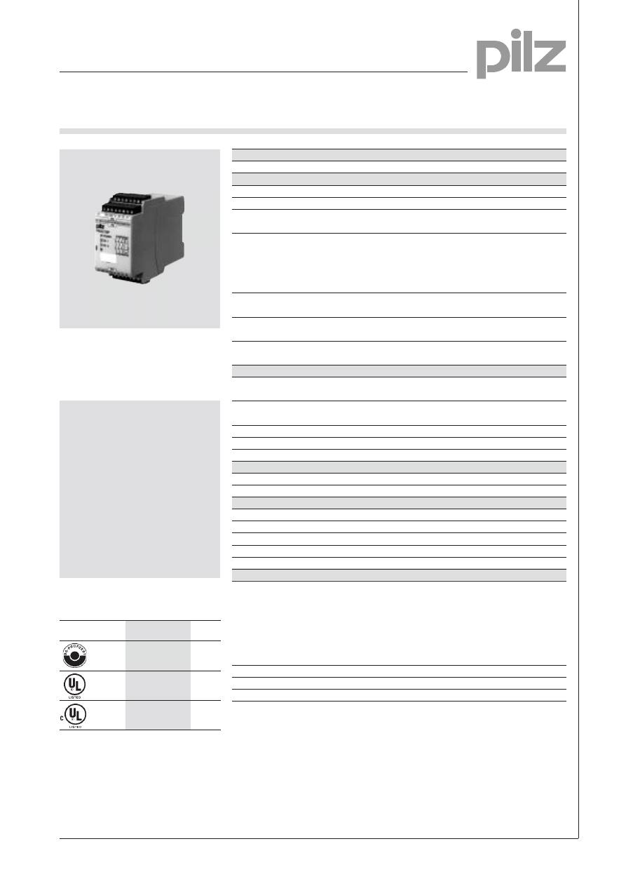
PNOZ X3P
EMERGENCY STOP switchgear and
safety gate monitor according to VDE
0113, 11/89, EN 60204-1, 12/97 and
IEC 204-1, 11/98.
Features
● Either monitored or automatic
start possible
● 1 semi-conductor output (K1/K2)
● Power supply 24 V DC and 24 V
AC contained in every device
● Safety gate function with
NC/NO combination
● 2-channel wiring only with
shorts across contacts detection
● Plug-in terminals
(Either screw terminals or cage
clamp terminals)
Approvals
Technical data
PNOZ X3P
Electrical data
Supply voltage
24 V AC, 24 V DC
Tolerance
85 ... 110 %
Power consumption
ca. 24 V DC, 35 mA
start and feedback loop
Switching capability according to
EN 60947-4-1, 02/01
AC1:
240 V/8 A/2000 VA
DC1: 24 V/8 A/200 W
EN 60947-5-1, 11/97
AC15: 230 V/5 A
(DC13: 6 switching cycles/min)
DC13: 24 V/6 A
Output contacts
3 safety contacts (NO),
1 auxiliary contact (NC)
Contact protection
10 A quick-acting or 6 A slow-acting
according to EN 60947-5-1, 11/97
Semiconductor output
24 V DC/20 mA, short-circuit-proof
external power supply
24 V DC ±20 %
Times
Switch-on delay
monitored start: max. 100 ms
auto./man. start: max. 0.3 s
Delay-on de-energisation
at EMERGENCY STOP: max. 80 ms
at mains off: max. 1 s
Recovery time
approx. 1 s
Simultaneity channel 1/2
¥
Power failure buffer
approx. 25 ms
Environmental data
Ambient temperature
-25 ... +55 °C
EMC
EN 50081-1, 01/92; EN 61000-6-2, 04/99
Mechanical Data: with cage clamp terminals
Terminal blocks per connection
2
Maximum cross section of ext. conductors
Flexible, without crimp connectors: 0.2 ... 1.5 mm
2
Stripping length
8 mm
Dimensions (H x W x D)
101 x45 x 122 mm
Weight
270 g
Mechanical data: with screw terminals
Max. cross section of outer conductor
single wire
flexible without end sleeve: 0.2 ... 2.5 mm
2
flexible with end sleeve: 0.25 ... 2.5 mm
2
multi-wire (2 wires of same cross section) flexible with end sleeve without plastic
sleeve: 0.25 ... 1 mm
2
flexible with TWIN end sleeve with
plastic sleeve: 0.5 ... 1.5 mm
2
Torque setting for screw terminals
0.5 ... 0.6 Nm
Dimensions (H x W x D)
94 x 45 x 122 mm
Weight
270 g
PNOZ X3P
●
●
●
NSG-D-2-161-10/03
Pilz GmbH & Co. KG, Sichere Automation, Felix-Wankel-Straße 2, 73760 Ostfildern, Germany
Telephone +49 711 3409-0, Telefax +49 711 3409-133, E-Mail: pilz.gmbh@pilz.de
EMERGENCY STOP Switchgears, Safety Gate Monitors
Category 4, EN 954-1
PNOZ X3P
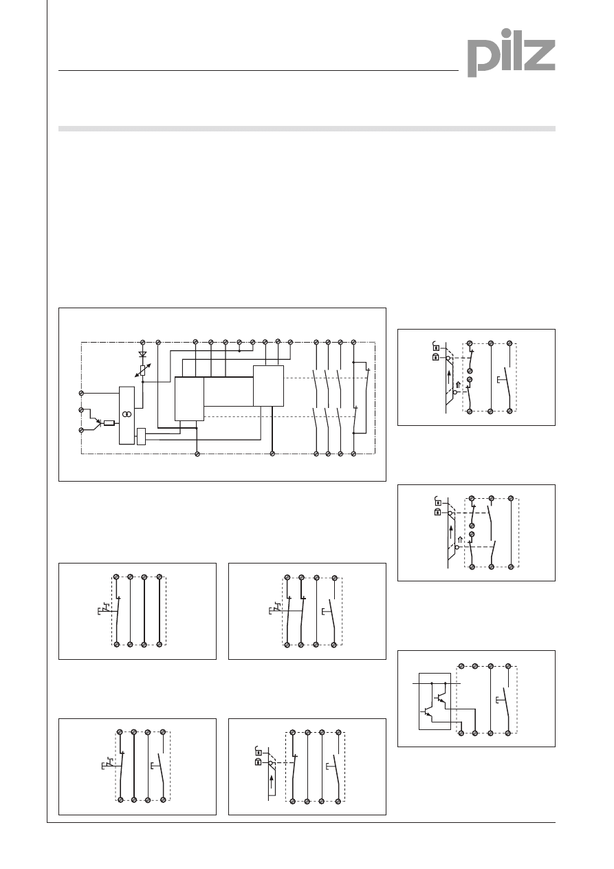
Schematic interior diagram
External wiring
● Example 1
Single-channel EMERGENCY STOP
wiring with automatic start
S11 S31
S13
S12
S14
S32
S21
S22
S1
● Example 2
Single-channel EMERGENCY STOP
wiring with monitored start
S11 S31
S33
S12
S34
S32
S21
S22
S1
S3
● Example 3
Dual-channel EMERGENCY STOP
wiring with monitored start
S21
S22
S12
S34
S32
S33
S11
S31
S1
S3
● Example 4
Single-channel safety gate control
with monitored start
S32
S34
S33
S31
S11
S22
S12
S21
S1
S3
● Example 5
Dual-channel safety gate control with
monitored start
S12
S34
S33
S11
S21
S32
S22
S31
S1
S2
S3
● Example 6
Dual-channel safety gate control with
automatic start
S12
S14
S13
S11
S21
S32
S22
S1
S2
S31
Input loop
NSG-D-2-161-10/03
UB
Input loop
Start/feedback loop
Safety
contacts
Auxiliary
contacts
Input loop
A1
A2
S13
S14
S12
S21
S34
41
42
S11
S22
S32
S31
13
33
14
34
K1
K2
23
24
&
Y32
Y31
CH1
CH2
Start
Unit
S33
Y30
Description
● 45 mm P-99-housing, on standard
rail, snap-on
● Relay outputs, positive-guided:
– 3 safety contacts (NO),
– 1 auxiliary contact (NC)
● Connection possibilities for
– EMERGENCY STOP button
– Safety gate limit button
– Start button
● Semi-conductor output signals
ready for operation
● LEDs for switching status
Channel 1, channel 2 and supply
voltage
● Contact multiplication and contact
amplification possible by external
contactors
Operating modes
● Single channel mode
● Dual channel mode
● Automatic start
● Manual start with monitoring
● Example 7
Dual channel light barrier control with
shorts across contacts detection by
BWS, with monitored start
S11
S12
S22 S34
S32
S33
S21
S31
S3
BWS
24 V DC
1
Pilz GmbH & Co. KG, Sichere Automation, Felix-Wankel-Straße 2, 73760 Ostfildern, Germany
Telephone +49 711 3409-0, Telefax +49 711 3409-133, E-Mail: pilz.gmbh@pilz.de
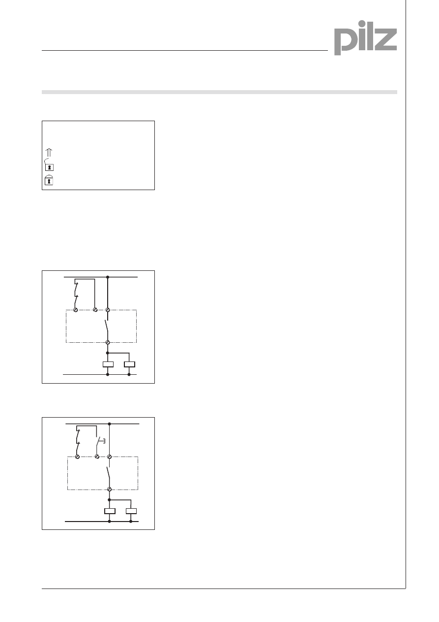
● Contact multiplication
The output contacts can be amplified
or multiplied by external contactors
with positive-guided contacts if
necessary.
– Single-channel control with
automatic start
– Single-channel control with
monitored start
14
K5
K6
13
S33
S34
K5
K6
1L1
1L2
S3
14
K5
K6
13
S13
S14
K5
K6
1L1
1L2
EMERGENCY STOP Switchgears, Safety Gate Monitors
Category 4, EN 954-1
PNOZ X3P
NSG-D-2-161-10/03
– Legend
S1/S2: EMERGENCY STOP or
safety gate switch
S3:
Start button
actuated element
gate not closed
gate closed

Pilz GmbH & Co. KG, Sichere Automation, Felix-Wankel-Straße 2, 73760 Ostfildern, Germany
Telephone +49 711 3409-0, Telefax +49 711 3409-133, E-Mail: pilz.gmbh@pilz.de
General data
Unless described otherwise than the device-specific
technical data.
Electrical data
Frequency range AC
50 ... 60 Hz
Residual ripple DC
160 %
Contact material
AgSnO
2
Continuous duty
100 %
Environmental data
EMC
EN 50081-1, 01/92; EN 61000-6-2, 03/00
Oscillations according to
Frequency: 10 ... 55 Hz,
EN 60068-2-6, 01/00
Amplitude: 0.35 mm
Environmental conditions
DIN IEC 60068-2-3, 12/86
Airgap and creepage distance
DIN VDE 0110-1, 04/97
Ambient temperature
-10 ... +55 °C
Storage temperature
-40 ... +85 °C
Mechanical data
Torque setting for terminals
0.6 Nm (screws)
Mounting position
any
Housing material
Thermoplast Noryl SE 100
Protection types
Installation room: IP 54
Housing: IP 40
Terminals: IP 20
The units were tested in accordance with the relevant standards current at
the time of development.
Order References
Type
U
B
Order No.
PNOZ X3P with cage clamp terminals
24 V DC, 24 V AC
787 310
PNOZ X3P with screw terminals
24 V DC, 24 V AC
777 310
EMERGENCY STOP Switchgears, Safety Gate Monitors
Category 4, EN 954-1
PNOZ X3P
NSG-D-2-161-10/03
Wyszukiwarka
Podobne podstrony:
pnoz x3p gb B5VW75QW7OGZ3YAVF6G43JUJXVPZSFBDAWURFWI
pnoz xe1 gb[1] OHVH62VRNRX27UG45CP4SMHI65HT275IHJKNDPA
PNOZ EX GB
PNOZ XV2P GB
PNOZ X2P GB
PNOZ 16SP GB
PNOZ XE2 GB
PNOZ XV2 1 GB
PNOZ XV3 GB
PNOZ E1P GB
PNOZ 2VQ GB
PNOZ XM1 GB
PNOZ X2C GB
PNOZ X3 1 GB
PNOZ 11 GB
PNOZ 16 GB
PNOZ X13 GB
więcej podobnych podstron