1
Emergency Stop Relays, Safety Gate Monitors
Category 4, EN 954-1
PNOZ X3.1
Emergency stop relay and safety
gate monitor in accordance with VDE
0113-1, 11/98, EN 60204-1, 12/97
and IEC 204-1, 11/98
Features
● Monitored manual or
automatic reset can be selected
● 1 semiconductor output (K1/K2)
● Each AC unit can be operated
with 24 VDC
● Safety gate function with
N/C-N/O combination
● Only dual-channel operation will
detect shorts across the input
contacts
● Input status display
Approvals
Description
● 45 mm P-97 housing,
DIN-Rail mounting
● Positive-guided relay outputs:
– 3 safety contacts (N/O)
– 1 auxiliary contact (N/C)
● Connections for
– E-STOP button
– safety gate limit switch
– reset button
● Semiconductor output signals
ready for operation
● LEDs for switching status of the
input circuits, channel 1/2 and
power
● Increase in the number of safety
contacts available by connecting
expander modules
Operating Modes
● Single-channel operation
● Dual-channel operation
● Automatic reset
● Monitored manual reset
PNOZ X3.1
Pending
●
●
Pilz GmbH & Co., Felix-Wankel-Straße 2, 73760 Ostfildern, Deutschland
NSG-D-2-244-06/00
Telefon +49 (7 11) 34 09-0, Telefax +49 (7 11) 34 09-1 33, E-Mail: pilz.gmbh@pilz.de
PNOZ X3.1 not shown
Technical Details
PNOZ X3.1
Electrical data
Supply voltage
AC: 230, 240 V
DC: 24 V
Tolerance
85 ... 110 %
Power Consumption
Approx. 2.5 W/5 VA
Voltage and current at the input,
24 V DC, 35 mA
reset circuits and feedback control loop
Switching capability in accordance with
EN 60947-4-1, 01/92
AC1:
240 V/8 A/2000 VA
DC1: 24 V/8 A/200 W
EN 60947-5-1, 11/97
AC15: 230 V/5 A; DC13: 24 V/6A
(DC13: 6 cycles/min)
Output contacts
3 safety contacts (N/O),
1 auxiliary contact (N/C)
Contact fuse protection
10 A quick or 6 A slow
in accordance with EN 60947-5-1, 11/97
Semiconductor outputs
24 V DC/20 mA, short-circuit protected
External supply voltage
24 V DC ±20 %
Times
Delay-on energisation
Monitored manual reset: max. 100 ms
Automatic reset: max. 0.3 s
Delay-on de-energisation
With E-STOP: max. 80 ms
With power failure: max. 1 s
Recovery time
Approx. 1 s
Simultaneity channel 1/2
¥
Supply interruption before de-energisation Approx. 25 ms
Environmental data
Ambient temperature
-25 ... +55 °C
Mechanical data
Maximum cross section of external
2 x 1.5 mm
2
or 1 x 2.5 mm
2
conductor
Single-core or multi-core
with crimp connector
Dimensions (H x W x D)
87 x 45 x 121 mm
Weight
420 g
Emergency Stop Relays, Safety Gate Monitors
Category 4, EN 954-1
PNOZ X3.1
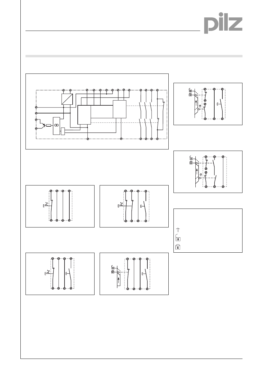
Internal wiring diagram
A1
A2
S13
S14
S12
S21
S34
41
42
S11
S22
S32
S31
13
33
14
34
K1
K2
23
24
&
Y32
Y31
CH1
CH2
Start
Unit
S33
AC
DC
B1
B2
+
-
UB
Input circuit
Start circuit
Safety
contacts
Auxiliary
contact
Input circuit
External wiring
● Example 1
Single-channel E-STOP wiring with
automatic reset.
S11 S31
S13
S12
S14
S32
S21
S22
S1
● Example 2
Single-channel E-STOP wiring with
monitored manual reset.
S11 S31
S33
S12
S34
S32
S21
S22
S1
S3
● Example 3
Dual-channel E-STOP wiring with
monitored manual reset.
S21
S22
S12
S34
S32
S33
S11
S31
S1
S3
● Example 4
Single-channel safety gate control
with monitored manual reset.
S32
S34
S33
S31
S11
S22
S12
S21
S1
S3
● Example 5
Dual-channel safety gate control with
monitored manual reset.
S12
S34
S33
S11
S21
S32
S22
S31
S1
S2
S3
● Example 6
Dual-channel safety gate control with
automatic reset.
S12
S14
S13
S11
S21
S32
S22
S1
S2
S31
– Key
S1/S2: E-STOP or safety gate
switch
S3:
Reset button
Switch operated
Gate open
Gate closed
Pilz GmbH & Co., Felix-Wankel-Straße 2, 73760 Ostfildern, Deutschland
NSG-D-2-244-06/00
Tel. +49 (7 11) 34 09-0, Fax +49 (7 11) 34 09-1 33, E-Mail: pilz.gmbh@pilz.de
1
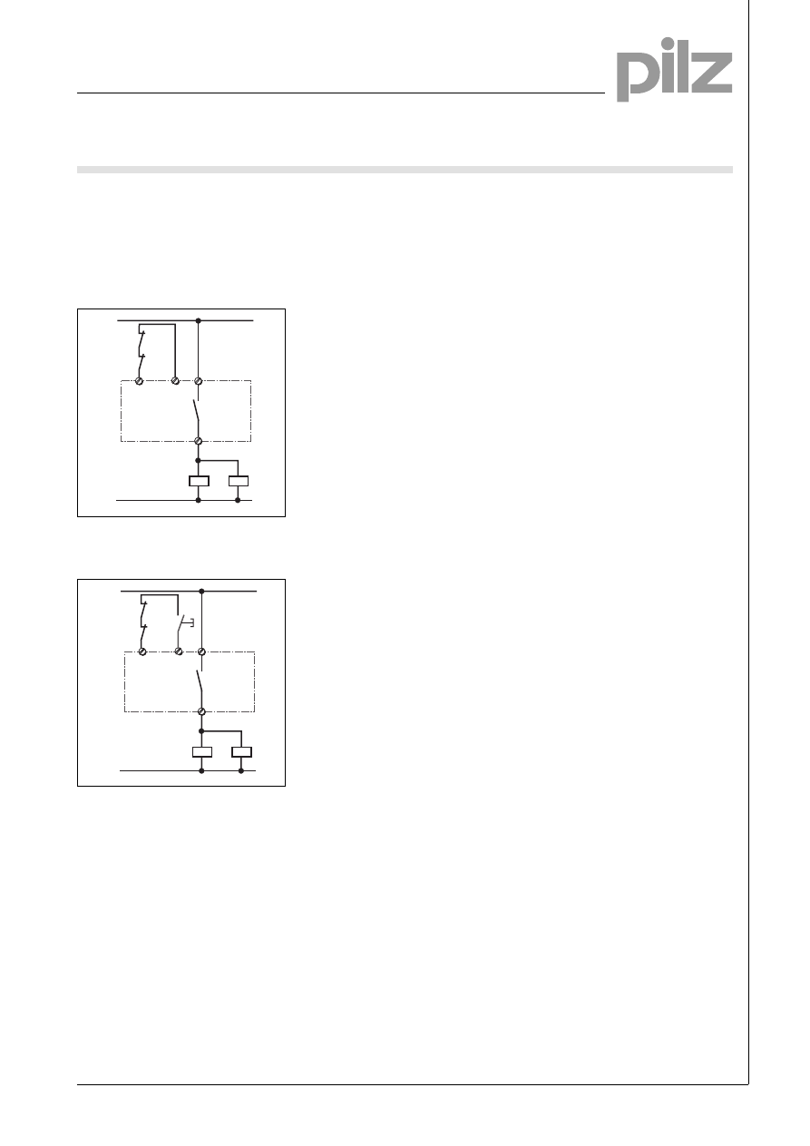
● Increase in safety contacts
The number of output contacts can
be increased by using expander
modules or relays/contactors with
positive-guided contacts.
– Operation with automatic reset.
– Operation with monitored manual
reset.
14
K5
K6
13
S33
S34
K5
K6
1L1
1L2
S3
14
K5
K6
13
S13
S14
K5
K6
1L1
1L2
Emergency Stop Relays, Safety Gate Monitors
Category 4, EN 954-1
PNOZ X3.1
Pilz GmbH & Co., Felix-Wankel-Straße 2, 73760 Ostfildern, Deutschland
NSG-D-2-244-06/00
Tel. +49 (7 11) 34 09-0, Fax +49 (7 11) 34 09-1 33, E-Mail: pilz.gmbh@pilz.de
Emergency Stop Relays, Safety Gate Monitors
Category 4, EN 954-1
PNOZ X3.1
Pilz GmbH & Co., Felix-Wankel-Straße 2, 73760 Ostfildern, Deutschland
NSG-D-2-244-06/00
Tel. +49 (7 11) 34 09-0, Fax +49 (7 11) 34 09-1 33, E-Mail: pilz.gmbh@pilz.de
General Technical Details
Unless stated otherwise in the technical details for the specific unit.
Electrical data
AC Frequency Range
50 ... 60 Hz
DC residual ripple
160 %
Contact material
AgSnO
2
Continuous duty
100 %
Environmental data
EMC
EN 50081-1, 01/92, EN 50082-2, 08/97
Vibration in accordance with
Frequency: 10 ... 55 Hz,
EN 60068-2-6, 04/95
Amplitude: 0.35 mm
Climatic suitability
DIN IEC 60068-2-3, 12/86
Airgap creepage
DIN VDE 0110-1, 04/97
Ambient temperature
-10 ... +55 °C
Storage temperature
-40 ... +85 °C
Mechanical data
Torque setting for connection terminals
0.6 Nm (screws)
Mounting position
Any
Housing material
Thermoplastic Noryl SE 100
Protection types
Mounting: IP 54
Housing: IP 40
Terminals: IP 20
Wyszukiwarka
Podobne podstrony:
PNOZ X3 GB
pnoz x3p gb B5VW75QW7OGZ3YAVF6G43JUJXVPZSFBDAWURFWI
pnoz xe1 gb[1] OHVH62VRNRX27UG45CP4SMHI65HT275IHJKNDPA
PNOZ EX GB
PNOZ XV2P GB
PNOZ X3P GB
PNOZ X2P GB
PNOZ 16SP GB
PNOZ X3 Data sheet 1002239 EN 02
PNOZ XE2 GB
PNOZ XV2 1 GB
PNOZ XV3 GB
PNOZ E1P GB
PNOZ 2VQ GB
PNOZ XM1 GB
PNOZ X2C GB
PNOZ 11 GB
więcej podobnych podstron