1
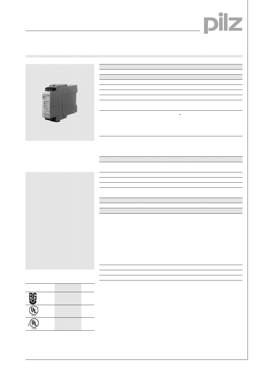
Emergency Stop Relays, Safety Gate PNOZ
Pilz GmbH & Co., Felix-Wankel-Straße 2, 73760 Ostfildern, Deutschland
NSG-D-2-289-11/01
Telefon +49 (7 11) 34 09-0, Telefax +49 (7 11) 34 09-1 33, E-Mail: pilz.gmbh@pilz.de
Emergency stop relay and safety
gate monitor in accordance with
VDE 0113-1, 11/98, EN 60204-1,
12/97 and IEC 204-1, 11/98
Features
● Monitored manual or automatic
reset can be selected
● 2 safe semiconductor outputs
● 1 auxiliary semiconductor out-
put
● Auxiliary output can also be
used as a diagnostic output
● Option for detecting shorts
across the input contacts
● Applications in accordance with
EN 954-1, 07/96, category 2, 3
or 4
● Self-test after U
B
is supplied
● Continuous self-monitoring
● Regular switch-off test of the
safety outputs
Approval
Technical details
PNOZ e1p
Electrical data
Supply voltage
24 VDC
Tolerance
80 ... 125 %
Power consumption
no load: 2 W
Residual Ripple DC
20 %
Outputs
2 safety outputs
1 auxiliary output
Switching capability
U
B
<26.5 V:
2 outputs under load: 2 A/50 W
1 output under load: 2.7 A/70 W
U
B
>26.5 V:
2 outputs under load: 1.5 A/40 W
Voltage and current at
input and reset circuits and
feedback control loop
24 VDC, 5 mA
auxiliary output and test pulse outputs
24 VDC/0.5 A
Times
Delay-on energisation
manual reset: 180 ms
automatic reset: 100 ms
Delay-on de-energisation
max. 35 ms
Switch-on delay
3 s (on initial reset once U
B
is supplied)
Simultaneity channel 1/2
¥
Max. Supply Interruption before
max. 20 ms
de-energisation
Environmental data
Storage temperature
-25 ... 70 °C
Mechanical data
Max. cross section of external conductor,
single core
flexible without crimp connector:
0.2 ... 2.5 mm
2
flexible with crimp connector:
0.25 ... 2.5 mm
2
multi-core conductor (2 conductors with
identical cross section)
flexible with crimp connector without
plastic sleeve: 0.25 ... 1 mm
2
flexible with TWIN crimp connector with
plastic sleeve: 0.5 ... 1.5 mm
2
Torque setting for terminals
0.5 ... 0.6 Nm (screws)
Dimensions (H x W x D)
87 x 22.5 x 121 mm
Weight
170 g
PNOZ e1p
●
●
●
Category 4, EN 954-1
PNOZ e1p
Emergency Stop Relays, Safety Gate
Category 4, EN 954-1
PNOZ e1p
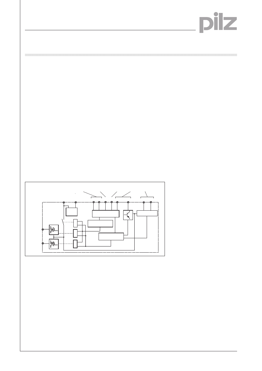
Description
● 22.5 mm P-99 housing,
DIN-Rail mounting
● Semiconductor outputs,
short-circuit proof:
– 2 safety outputs
– 1 auxiliary output
– 2 test pulse outputs
● Connections for
– E-STOP button
– safety gate limit switch
– evaluation device for proximity
switches
– safety mats and connecting
blocks made by Haake
– Reset button
● Auxiliary output can also be used
as a diagnostic output
It is possible to program the driver
for reading diagnostic data
yourself. However, the CD „PLC
S12
S11
S34
S22
Y5
14
24
A1
A2
Y32
S21
Input
circuit
Reset circuit/
feedback
control loop
U
B
Power
supply
&
Mode
Auxiliary
output
Test pulse
outputs
Safety
outputs
&
&
µController 2
µController 1
Y4
Input circuit
Test pulse
outputs
Internal wiring diagram
Pilz GmbH & Co., Felix-Wankel-Straße 2, 73760 Ostfildern, Deutschland
NSG-D-2-289-11/01
Telefon +49 (7 11) 34 09-0, Telefax +49 (7 11) 34 09-1 33, E-Mail: pilz.gmbh@pilz.de
Drivers for PNOZelog“ is also
available. This contains pre-
programmed drivers for the
following controllers:
- SIMATIC S7
● LEDs for switching status and
faults in channel 1/2 and for
supply voltage
● Shorts across the input contacts
are detected by means of test
pulse outputs
● Increase in the number of safety
contacts available by connecting
expander modules
Operating modes
● Single-channel operation
● Dual-channel operation
● Automatic reset
● Monitored manual reset
1
Emergency Stop Relays, Safety Gate
Category 4, EN 954-1
PNOZ e1p
● Example 2
Dual-channel emergency stop wiring
with monitored manual reset without
short-circuit recognition
● Example 5
Dual-channel safety gate control with
monitored manual reset without
short-circuit recognition
● Example 4
Dual-channel safety gate control with
automatic reset without start-up test
and without short-circuit recognition
● Example 3
Dual-channel emergency stop wiring
with monitored manual reset and
shorts across the input contacts are
detected
● Example 6
Dual-channel safety gate control with
automatic reset and start-up test,
shorts across the input contacts are
detected
External wiring
● Example 1
Single-channel emergency stop
wiring with monitored manual reset
without short-circuit recognition
● Increase in the number of contacts
The number of output contacts can
be increased by using expander
modules or relays/contactors with
positive-guided contacts.
Pilz GmbH & Co., Felix-Wankel-Straße 2, 73760 Ostfildern, Deutschland
NSG-D-2-289-11/01
Telefon +49 (7 11) 34 09-0, Telefax +49 (7 11) 34 09-1 33, E-Mail: pilz.gmbh@pilz.de
A1
S12 S22
A1
Y4
S1
A1
S34
S3
S11 S21
S12 S22
A1
S34
A1
Y4
S1
S3
S34
S11
A1
A1
S12
S22
S1
S1
S2
A1
Y4
A1 A1
S12 S22
A1
S34
A1
Y4
S1
S3
S34
A1
A1
A1
S12
S22
S1
S3
S1
S2
A1
Y4
S11
S21
S12
S22
S1
S1
S2
S21
S34
A1
Y4
– Key
S1/S2: E-STOP or safety gate switch
S3:
Reset button
Switch operated
Gate open
Gate closed
14
K2
K3
24
1L1
1L2
A1
A2
A1
S34
K3
K2
S3
PNOZ e1p

Emergency Stop Relays, Safety Gate
Category 4, EN 954-1
PNOZ e1p
Pilz GmbH & Co., Felix-Wankel-Straße 2, 73760 Ostfildern, Deutschland
NSG-D-2-289-11/01
Telefon +49 (7 11) 34 09-0, Telefax +49 (7 11) 34 09-1 33, E-Mail: pilz.gmbh@pilz.de
General details
Unless stated otherwise in the technical details for the specific unit
Electrical data
AC frequency range
50 ... 60 Hz
DC residual ripple
160 %
Contact material
AgSnO
2
Continuous duty
100 %
Environmental data
EMC
EN 50081-1, 01/92, EN 61000-6-2, 04/99
Vibration in accordance with
EN 60068-2-6, 04/95
Frequency: 10 ... 55 Hz,
Amplitude: 0.35 mm
Climatic suitability
DIN IEC 60068-2-3, 12/86
Airgap creepage
DIN VDE 01101 Part 1, 04/97
Ambient temperature
-10 ... +55 °C
Storage temperature
-40 ... +85 °C
Mechanical data
Torque setting for connection terminals
0.6 Nm (screws)
Mounting position
Any
Housing material
Thermoplastic Noryl SE 100
Protection types
Mounting: IP 54
Housing: IP 40
Terminals: IP 20
The units were tested in accordance with the standards applicable at the
time of development.
Order reference
Type
U
B
Order number
PNOZ e1p
24 VDC
774 130
Order references accessories
Description
Order number
PLC Drivers for PNOZelog
874 130...
1)
1)
When ordering, please state the type of licence you require after the order number
(..B for basic licence, ..K for copy licence, ..G for general licence, ..U for update licence),
e.g. 301 400B.
Wyszukiwarka
Podobne podstrony:
pnoz x3p gb B5VW75QW7OGZ3YAVF6G43JUJXVPZSFBDAWURFWI
pnoz xe1 gb[1] OHVH62VRNRX27UG45CP4SMHI65HT275IHJKNDPA
PNOZ EX GB
PNOZ XV2P GB
PNOZ X3P GB
PNOZ X2P GB
PNOZ 16SP GB
PNOZ XE2 GB
PNOZ XV2 1 GB
PNOZ XV3 GB
PNOZ 2VQ GB
PNOZ XM1 GB
PNOZ X2C GB
PNOZ X3 1 GB
PNOZ 11 GB
PNOZ 16 GB
PNOZ X13 GB
więcej podobnych podstron