1
Pilz GmbH & Co. KG, Sichere Automation, Felix-Wankel-Straße 2, 73760 Ostfildern, Germany
Telephone +49 711 3409-0, Telefax +49 711 3409-133, E-Mail: pilz.gmbh@pilz.de
Emergency Stop Relays, Safety Gate Monitors
Category 4, EN 954-1
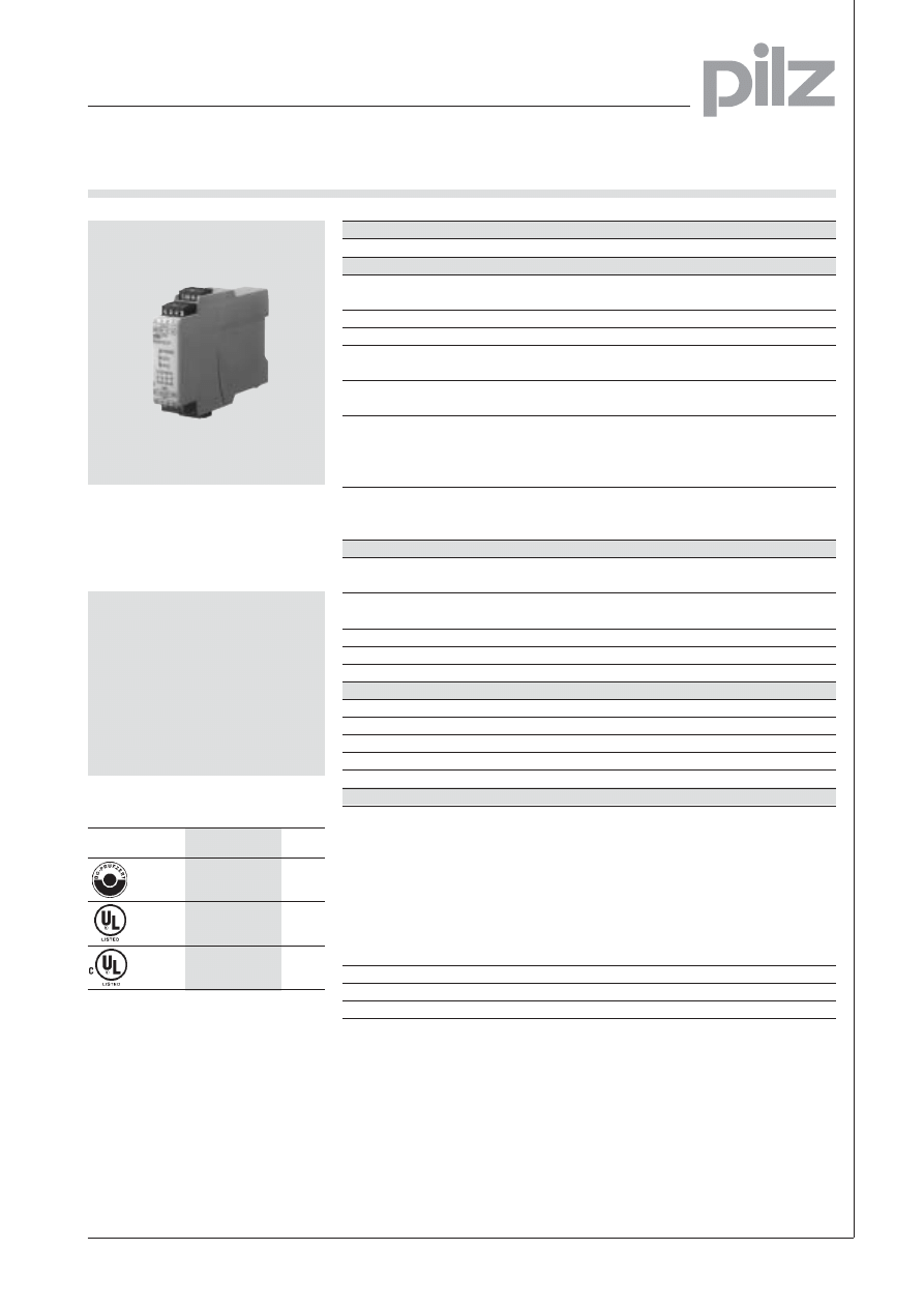
PNOZ X2.7P
EMERGENCY STOP switchgear and
safety gate monitor according to
EN 60204-1 (VDE 0113-1), 11/98 and
IEC 60204-1, 10/97
Features
● monitored start
● 1-channel or 2-channel wiring
with or without shorts across
contacts detection
l Plug-in connection terminals
(Either screw terminals or cage
clamp terminals)
Approvals
Technical data
PNOZ X2.7P
Electrical data
Power supply
AC: 24 V
DC: 24 V
Tolerance
85 ... 110 %
Power consumption
AC: Approx. 2 VA, DC: Approx. 2 W
Voltage and current at input,
24 V DC, 25 mA
start and feedback loop
Output contacts
3 safety contacts (NO)
1 auxiliary contact (NC)
Switching capability according to
EN 60947-4-1, 02/01
AC1:
240 V/6 A/1500 VA
DC1: 24 V/6 A/150 W
EN 60947-5-1, 11/97 (DC13:6 cycles/min)
AC15: 230 V/5 A; DC13: 24 V/4 A
Contact protection according to
Blow-out fuse: 6 A quick or 4 A slow
EN 60947-5-1, 11/97
Safety cut-out: 24 V DC: 4 A,
Characteristic B/C
Times
Pickup delay
monitored start: max. 100 ms
auto./man. start: max. 0.35 s
Delay-on de-energisation
at EMERGENCY STOP: max. 30 ms
at mains off: max. 150 ms
Recovery time
approx. 1 s
Simultaneity channel 1 and 2
¥
Power failure buffer
approx. 10 ms
Mechanical Data: with cage clamp terminals
Terminal blocks per connection
2
Maximum cross section of ext. conductors
Flexible, without crimp connectors: 0.2 ... 1.5 mm
2
Stripping length
8 mm
Dimensions (H x W x D)
101 x 22.5 x 121 mm
Weight
200 g
Mechanical data: with screw terminals
Maximum cross section of ext. conductors
Single-core
Flexible, without crimp connectors:
0.2 ... 2.5 mm
2
Flexible with crimp connectors:
0.25 ... 2.5 mm
2
Multi-core
Flexible, with crimp connectors but
(2 conductors with same cross-section)
without plastic sheath: 0.25 ... 1 mm
2
Flexible, with TWIN-crimp connectors
and plastic sheath: 0.5 ... 1.5 mm
2
Torque setting for screw terminals
0.5 ... 0.6 Nm
Dimensions (H x W x D)
94 x 22.5x 121 mm
Weight
200 g
Description
● 22,5 mm P-99 housing, on
standard rail, snap-on
● Relay outputs, positive-guided:
–
3 safety contacts (NO)
–
1 auxiliary contact (NC)
● Connection possibilities for
–
EMERGENCY STOP switch
PNOZ X2.7P
●
●
●
NSG-D-2-331-10/03
Operating modes
● Single channel mode
● Dual channel mode without shorts
across contacts detection
● Dual channel mode with shorts
across contacts detection
● Manual start with monitoring
–
Safety gate limit switch
–
Light guard
–
Start switch
● LEDs for switching status Channel
1 and 2 and power supply
● Contact multiplication and
Contact amplification possible by
external contactors
Pilz GmbH & Co. KG, Sichere Automation, Felix-Wankel-Straße 2, 73760 Ostfildern, Germany
Telephone +49 711 3409-0, Telefax +49 711 3409-133, E-Mail: pilz.gmbh@pilz.de
Emergency Stop Relays, Safety Gate Monitors
Category 4, EN 954-1
PNOZ X2.7P
● Increase in safety contacts
The number of output contacts can
be increased by using expander
modules or relays/contactors with
positive-guided contacts.
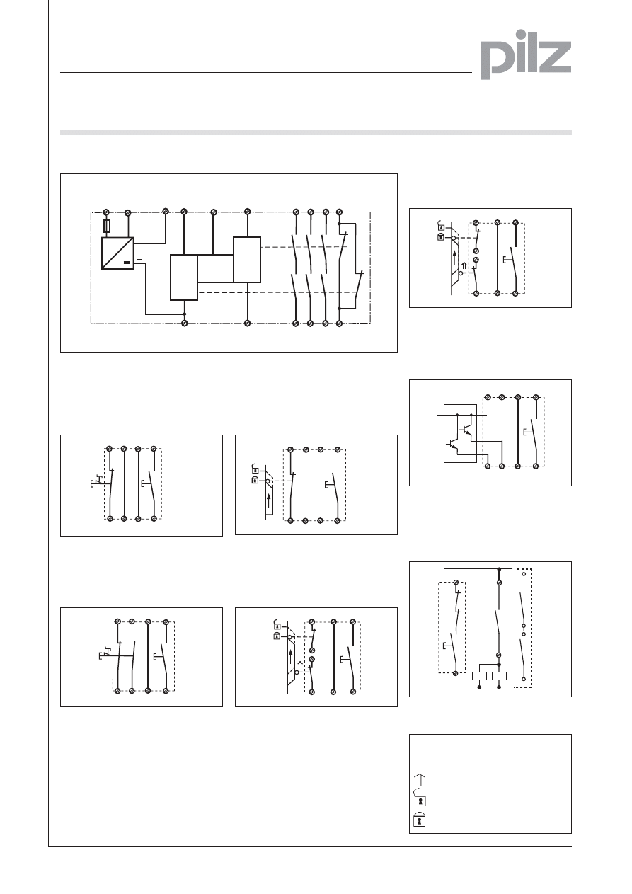
External wiring
● Example 1
Single-channel EMERGENCY STOP
wiring with monitored start
● Example 2
Dual-channel EMERGENCY STOP
wiring without shorts across con-
tacts detection with monitored start
● Example 4
Dual-channel safety gate control with
shorts across contacts detection and
monitored start
Schematic interior diagram
● Example 6
Dual channel light barrier control with
shorts across contacts detection by
BWS, with monitored start
● Example 3
Single-channel safety gate control
with monitored start
● Example 5
Dual-channel safety gate control
without shorts across contacts
detection and monitored start
NSG-D-2-331-10/03
S11 S12
S12
S34
S52
S21
S22
S1
S3
S12 or S52
S11
S12
S22 S34
S52
S12
S21
S11
S1
S3
S52 S34
S12
S11
S11
S22
S12
S21
S1
S2
S3
S11
S52
S12
S11
S22
S21
S34
S12
S3
S11
S12
S22 S34
S52
S12
S21
S11
S3
BWS
24 V DC
13
14
K5
S12
S34
K5
K6
K5
K6
K6
S3
– Legend
S1/S2: EMERGENCY STOP or safety
gate switch
S3:
Start switch
actuated element
gate not closed
gate closed
A1 (L+) A2 (L-)
S22
S12
S21
S11
S34
13
14
K1
K2
23
24
S52
33
34
41
42
U
B
+
~
CH1
Start
Unit
CH2
Input Ciruit
Reset
circuit
Safety
contacts
Auxiliary
contact
Input Ciruit
Input Ciruit
S52 S34
S12
S11
S22
S12
S21
S1
S3
S12 or S52
1
Pilz GmbH & Co. KG, Sichere Automation, Felix-Wankel-Straße 2, 73760 Ostfildern, Germany
Telephone +49 711 3409-0, Telefax +49 711 3409-133, E-Mail: pilz.gmbh@pilz.de
Emergency Stop Relays, Safety Gate Monitors
Category 4, EN 954-1
PNOZ X2.7P
NSG-D-2-331-10/03
General Technical Data
Unless stated otherwise in the technical details for the specific unit
Electrical Data
Frequency Range AC
50 ... 60 Hz
Residual Ripple DC
160 %
Contact Material
AgSnO
2
Continuous Duty
100 %
Environmental Data
EMC
EN 61000-6-3, 10/01
EN 61000-6-3, 10/01
Vibration in accordance with
Frequency: 10 ... 55 Hz,
EN 60068-2-6, 04/95
Amplitude: 0.35 mm
Climatic Suitability
DIN IEC 60068-2-3, 12/86
Airgap Creepage
DIN VDE 0110 part 1, 04/97
Ambient Temperature
-10 ... +55 °C
Storage Temperature
-40 ... +85 °C
Mechanical Data
Torque Setting on Connection Terminals
0.6 Nm (screws)
Mounting Position
Any
Housing Material
Front: ABS UL 94 V0
Housing; PPO UL 94 V0
Protection
Mounting: IP 54
Housing: IP 40
Terminal Range: IP 20
The units were tested in accordance with the relevant standards current at
the time of development.
Order References
Type
U
B
Order No.
PNOZ X2.7P with cage clamp terminals
24 V DC, 24 V AC
787 305
PNOZ X2.7P with screw terminals
24 V DC, 24 V AC
777 305
Wyszukiwarka
Podobne podstrony:
pnoz x2 7p gb TFLL2KJYRRWLH57VUHMA4GNT5EFCG5Y7YNKDHWI
pnoz x2 8p gb N6UOWRFWK2SGXLCONW7K7QZNBF6QBZQMGRHLKEQ
PNOZ X2 3P GB
PNOZ X2 1VP GB
PNOZ X2 4V gb
PNOZ X2 5P GB
PNOZ X2 GB
PNOZ E1 1P GB
PNOZ XV3 1P GB
PNOZ XV2 1P GB
PNOZ E3 1P gb
pnoz x3p gb B5VW75QW7OGZ3YAVF6G43JUJXVPZSFBDAWURFWI
pnoz xe1 gb[1] OHVH62VRNRX27UG45CP4SMHI65HT275IHJKNDPA
PNOZ EX GB
PNOZ XV2P GB
PNOZ X3P GB
PNOZ X2P GB
więcej podobnych podstron